N O T I C E THIS DOCUMENT HAS BEEN REPRODUCED FROM MICROFICHE. ALTHOUGH IT IS RECOGNIZED THAT CERTAIN PORTIONS ARE ILLEGIBLE, IT IS BEING RELEASED IN THE INTEREST OF MAKING AVAILABLE AS MUCH INFORMATION AS POSSIBLE https://ntrs.nasa.gov/search.jsp?R=19820007241 2018-07-10T14:54:15+00:00Z
Transcript
N O T I C E
THIS DOCUMENT HAS BEEN REPRODUCED FROM MICROFICHE. ALTHOUGH IT IS RECOGNIZED THAT
CERTAIN PORTIONS ARE ILLEGIBLE, IT IS BEING RELEASED IN THE INTEREST OF MAKING AVAILABLE AS MUCH
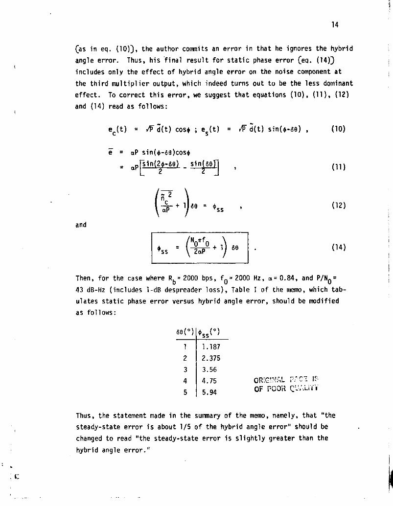
with a table which computes ass for larger values of tilts. The latter
three values of ass
in this table, corresponding to respective tilts of
0.3, 0.5 and 1.0 dB, should be corrected to read 0'.0108, 0.018 and 0.03920.
One further point of correction, although probably of second-order
importance, deserves mention at this time. The parameter a in the above
equation which ordinarily characterizes the arm filtering degradation on
the SxS term in the loop when both arm filters are identical should be
modified for the case where the arm filters are different. In particular,
we would now have (analogous to eq. (42)) for the noise effects
foo[Hl(w) H2*(w) + H1*(w) H2 (w) Sd(w) dw
16
where Sd (w) is the data modulation spectrum and H l (w), H2 (w) are the am
filter transfer functions, i.e.,
H i (w) _ —f- i=1,2
1 4 3 f.i
Substitution of H i (w) into the above expression for a and simplifying yields
(l+x'11+`^w l ! w2 ) dwa = ^2^ 2 Sd(w) 2n
1 + l wl^ 1 + \w2/
which, for a small 3-dB cutoff frequency difference, is approximately a,
as previously computed for identical arm filters.
Thus, in conclusion, the hybrid imperfection effect dominates
over the imperfect filtering effects, and the static phase error induced
is on the order of the hybrid angle error.
3.1.5 IUS Memo No. 117
The mean slip time of the carrier-tracking loop in the IUS-TDhS
transponder is computed at both threshold conditions CC/N0 = 33.7 dB-Hz,
R = 125 bps) and strong signal conditions CC/N 0 = 43.7 dB-Hz, R B = 2000 bps).
The loop is configured as a standard Costas loop with an input signal hav-
ing an unbalanced QPSK format characterized as follows. The received sig-
nal has a PN spread data modulation on the strong (I) channel and PN only
on the weak (Q) channel. The power ratio is fixed at 10:1. After being
despread by the I-channel PN code, the signal retains an unbalanced QPSK
format with data modulation only (assuming "perfect" despreading with a
fixed despreading loss) on the I-channel, and PN only (the product of the
in-phase and quadrature PN codes) on the Q-channel. This signal serves as
the Costas loop input. As such, the evaluation of the loop's phase error
variance due to thermal noise follows along the lines of previous analyses
of bi hase Costas loops with passive arm filters and unbalanced QPSK in-
puts. In making this statement, we tacitly make the assumption that the
17
PN code on the Q-channel behaves as a random data modulation of rate R c =
fc , where f is the PN chip rate (i.e., 3x10⁶ Mchips/s). Thus, it is notsurprising that eq. (22) of the memo agrees with [1, eqs. (28) and (30)]
after the appropriate changes in notation.
Next, the memo evaluates the phase error variance component due
to oscillator phase noise. The phase noise model, based on IUS phase noise
specifications, was assumed to have a power spectral density which varied
as O f6 . For simplicity of computation of the phase error variance due tophase noise, the out-of-band loop transfer function 1- H(f) was assumed to
behave like a "brick wall" filter having zero value below the loop natural
frequency and unity value above this frequency. Finally, the two phase
error variance components ( that due to thermal noise and that due to oscil-
lator phase noise) are added to give the total phase error variance a202.
Before determining the mean slip time of the Costas loop, one
needs, in addition to the total phase error variance, the steady-state
phase error due to dynamics such as a residual carrier frequency rate of
of Hz/sec. For a second -order Costas loop, these two parameters are
related by
2nof
20ss 2 2(wn
where w is the loop's radian natural frequency which, for a 0.707 loop
damping, is related to the loop bandwidth BL by wn = 1.89 B
L. Having now
determined a202 and 0ss , the author computes mean slip time T (normalized
by the loop bandwidth) from the formula
BST = 1.5 exp 1 ' 2( 1 - sin 2fss,
a20
1 , 1.2 - sin _ 4,ref 1 2.5 exp 1 si --+
( )
1a2^
2(1.89^Bt2
(1)
28
This relation is valid for a second-order Costas loop with an active loop
filter and was originally obtained from simulation results on an analogous
phase-locked loop.
The author concludes with an evaluation of (2) for threshold and
strong signal conditions, and Ai = 70 Hz/sec. At threshold, a value of
BL = 25 Hz maximizes T, whose value is 6000 sec (10 min). In the absence
of phase noise and loop dynamics (Ai), T is monotonically decreasing with
increasing 8L. At strong signals, the same B
L = 25 Hz produces T>> 104 min.
The results given in this memo are obtained by straightforward
application of previously derived results and, as such, need no further
i. investigation.
3.1.6 IUS Memo No. 123
The effect of the delay induced by the arm filters in the IUS-
TDRS Costas loop on loop bandwidth and, hence, the phase error variance, is
investigated. The key step in the analysis is the approximation made with
respect to the signal e u (t) appearing at the upper arm filter output,
namely, that the effect of this filter on the data modulation and the loop
phase error are separable. More specifically, letting H(s) denote the arm
filter transfer function, then
eu (t) _ ►V H(p)[d(t) sin #(t)] (1)
which, for small 0. becomes
eu (t) _ F H ( p )[d(t) 4(t)] (2)
is approximated by
eu (t) _ A (H ( p ) d(t))(H( p ) 0(t)) (3)
where p has been used to denote the Heaviside operator. It is argued that
(3) follows from (2), provided that "the lowpass arm filter H(s) does not
seriously distort the baseband data stream." Although there appears to be
no approximate mathematics that can lead one from (2) to (3), there is a
t`
19
reasonable plausibility argument that one can use to make this step
somewhat believable. Typically, the #(t) process being slowly varying
with respect to d(t) appears as an envelope modulation on d(t) which,
when passed through the arm filter, is essentially unaffected in ampli-
tude but is shifted (delayed) by the arm filter group delay Thus, if
we approximate #(t) as a single-frequency (say, w 0 ) beat note, then
H(t) #(t) = #Ct- td, where t0 = arg Q wd/w0 is a good approximation
to the envelope modulation on the filtered data stream.
Making the above approximation, the author proceeds to find a
simple relation between the loop bandwidth (including the arm filter
delay effect), say B L (D), and the zero-delay loop bandwidth BLO , namely,
2
BLO1 - 2c amO
D 2
(4)
where C is the loop damping and D = w noT, with wnO
the zero-delay radian
natural frequency and T the time constant of the single-pole arm filter
H(s). Since wnO
and B LO are related by
NO = 2B LO( 4; ( 5 )1 +4C
then (4) can be alternately be written as
BL (D) - 1 0^)
28 L 1 1+ -f
ao0
Clearly, the mean-square phase jitter with delay becomes unbounded when
BLOT = (1 + 4c2)/4 .
(7)
t:
^ti
20
For c = 0.707, DLO
2 75 Hz and a 100-Hz 3-dB cutoff frequency (i.e., T =
1/2x(1001 = 0.00159), the increase in RMS phase jitter is only 9% cc4(0)/
a®01.09).
The author follows the computation of mean-square phase jitter
with a discussion of the effect of the arm filter delay on loo; stability,
as determined by Routh's stability criterion, and the root locus plot.
The interesting (but not too surprising) result is that the loop bandwidth
at which the loop becomes unstable is also determined from (7), namely,
the same value at which the mean-square phase error variance becomes
unbounded.
Finally, we wish to call attention to a similar study [2) with
similar results in which the effect of delay on the loop bandwidth and
stability of a data-aided loop (DAL) were investigated, thus lending more
credibility to the analysis performed in this memo. The DAL, which is
also used for tracking suppressed carrier signals, has much similarity to
the conventional Costas loop.
3.1.7 IUS Memo No. 110
This memo is the only one in the SSP analysis section which was
not previously critiqued by Axiomatix. In particular, it addresses the
mean time to declare out-of-lock for the code-tracking loop, both when
the signal is present and when it is absent. The lock detector algorithm
is of the "n-out-of-n" type wherein n (typically, 16) successi ve below-
threshold events are required to declare an out-of-lock condition. If an
above threshold even occurs anywhere along the way, the algorithm returns
the system to its initial state and resets the below-threshold count to
zero.
The mean time to out-of-lock performance of such a discrete
time lock detector algorithm is best determined by modeling the algo-
rithm as a 17-state Markov chain (the 17th state being the absorbing
state, namely, an out-of-lock declaration) and applying the well-known
theory for such chains to this particular case. Actually, for n 4 5, a
formula for this mean-time performance was determined by brute force
(direct) calculation in a previous memo by the author (see TRW IOC No.
SCTE-50-76-275/JKH). Thus, this memo serves to merely formalize the
W
21
i
validity of this result for all values of n. In particular, the mean
time to out-of-lock, T,•is simply given by
= nlT _ Tq DWELL
where TDWELL
is the dwell time per state (assumed equal for all states),
i.e., the time between threshold tests of the integrator output, and q is
the probability of a below-threshold event for any given threshold tEst.
Since, when signal is absent, q = 0.95 and, when signal is pres-
ent, q - 0.5, then for n = 16 and a 50-ms dwell time; the corresponding
values of T are found to be 1.27 seconds and 109.2 minutes, respectively.
The straightforward nature of these results and the absence of
complicating assumptions requires that no further investigation be
performed.
In the STDN dual mode section of the CDR package, two memos
were written which pertain to the analysis and design of the lock detector,
noncoherent, AGC and open-loop frequency acquisition circuits associated
with the carrier-tracking loop of the IUS transponder. Since the first of
these two memos (#122) assumes knowledge of the second (#124), we shall
start by critiquing the second.
3.1.8 IUS Memo No. 124
In the STDN dual mode of the IUS transponder, an open-loop fre-
quency acquisition scheme is used which involves linear sweeping of the
VCO frequency to bring the initial frequency uncertainty within the Pull-
in range of the loop (typically on the order of the loop bandwidth).
Since the loop is open during this sweep interval, an auxiliary detection
circuit must be used to determine when to remove the sweep and simultane-
ously* close the loop. This auxiliary detector consists of a coherent
amplitude detector (CAD) followed by a lowpass filter and threshold device.
In the actual frequency acquisition scheme used in the STDNmode, the sweep continues for an additional 4 ms after the detector indi-cates acquisition has been achieved to all for the processing time of themicroprocessor which controls the closing of the loop.
22
An instantaneous crossing* of the threshold by a signal at the input to
this device indicates acquisition whereupon the sweep is terminated and
the loop closed.
Such a half-wave rectifier type of open-loop frequency search
circuit has been previously described in [3]. This mew discusses its
application to the IUS transponder in the STDN dual mode. In particular,
computer simulation and laboratory test results are obtained for the wave-
forms at the output of the lowpass RC decision filter (in the absence of
noise) so as to enable selection of this filter's 3-dB cutoff frequency s
for a given sweep rate R (Hz/sec), normalized (to the peak signal ampli-
tude) threshold level d, and closed-loop bandwidth f l . Indeed, it is
shown that if, for a given initial frequency offset outside the loop's
pull-in range, B is too small, then, depending on the initial phase dif
ference 40 between the input signal and the swept VCO, the threshold may
or may not be exceeded as the VCO is swept through the pull-in range.
Increasing s helps this situation; however, if S is too large, then the
threshold is exceeded while the loop is still outside its pull-in range.
Hence, the sweep will be terminated and, consequently, the loop closed
prematurely.
The author provides what appears to be a reasonable rule of
thumb for the selection of s, namely, the peak value of the normalized
detector output frequency response H(f), evaluated at the edge of the
pull-in range (assumed equal to the loop bandwidth f l ) should be less
than the normalized threshold a. For a single-pole decision filter (B =
3-dB frequency), it is straightforward to show that the above is equiva-
lent to the conditiont
< fl s
Again. because of the 4-ms processing time of the micropro-cessor, a "stretching" or hold circuit follows the threshold detector toprevent situations where the input signal reverses and falls belowthreshold in less than 4 ms, i.e., sharp peaks.
'The author does not actually write this inequality in thisform although it is obtained by obvious steps from the results giventherein. Also note that this result is Independent of the sweep rate Ralthough the actual simulation results were performed for R-4000 3 Hz/s.
is
23
Thus, for d = 0.5 and f l = 400 Hz (STDN parameters), we obtain Q < 400/
d3 = 231 Hz (the author uses the approximate value 250 Hz).
The next area of investigation was the calculation of acquisi-
tion probabilities which were performed by computer simulation (in the
absence of noise) in view of the difficulty of obtaining these results
analytically. Note again that, although the additive noise was assumed
to he Absent, the probability of acquisition is, in general, less than
one u;ie to dependence of the acquisition process on the initial phase
difference +0 . The author compares the acquisition probability results
obtained by the above-mentioned simulation with experimental results
obtained in [3]. In some cases, there appears to be reasonable agreement
whereas, in other cases, there seems to be no match at all. Since, for
the latter situation, the author of [3] does not state to which of the
three possible open-loop implementations (one mixer and one half-wave
rectifier, one mixer and one full-wave rectifier, or two mixers and two
full-wave rectifiers) his results apply, one is unable to resolve the
discrepancy. Herein lies one of the principal rea jns for issuing IUS
Memo #124 in the first place, namely, to point out the lack of agreement
between the previously published experimental results and the computer
simulation results obtained by the author of the memo.
Finally, this memo concludes with a discussion of how the results
might be extended to account (in a very rough sense) for the effects of
additive noise.
In the opinion of Axiomatix, the results documented in this memo
represent a significant contribution to the understanding of the perfor-
mance and behavior of open-loop frequency acquisition techniques of the
type described therein. As such, the results are given in a sufficiently
general parametric form as to he useful in applications outside of the
IUS transponder. Perhaps the only area which would require further inves-
tigation would be the noise-present case, where computer simulation could
again be used (although with more difficulty) rather than the rough exten-
sion (valid only for high SNR) approach given in the memo. Indeed, the
entire subject of frequency acquisition in noise is an area of research
where much needs to be done.
1
i^
24
3.1.9 IUS Memo No. 122
Associated with the open-loop frequency acquisition technique
described in IUS Memo #124 is the lock detector of the STON dual made
whose functions are to close the tracking loop and stop and sweep* when
frequency acquisition has been completed. The indication that frequency
acquisition is complete is a high (a°)ove threshold) signal from the
sampled-and-held output of the threshold device in the frequency acquisi-
tion circuit. Thus, this signal serves as the input to the lock detector
whose control algorithm is as follows: When the loop is initially open,
a single high sampled-threshold output shall close the loop. Two succes-
sive high-threshold „dtputs are required to terminate the sweep. Also,
when the loop is initially closed and in lock, two successive low-threshold
outputs are required to open the loop and reinstate the sweep.
The purpose of this memo is to determine decision filter band-
width and threshold settings for the above circuit, taking into account
both the hold circuit at the sampled-threshold output and the noncoherent
AGC (NAGC) which accompanies the loop. As in the previous lock detector
analyses (see IUS Memos #'125 and 110), the theory of finite Markov chains
is used to determine the mean time to false alarm (falsely close the loop
and falsely disable the sweep) performance. Other computations include
probability of false alarm (falsely closing the loop and falsely disabling
the sweep) and accidental restart (falsely open the loop).
For the NAGC effects, the author assesses the increase in AGC
gain in going from acquisition CS/N0 = 46 dB-Hz) to tracking Ceffec:ivetS/N0 = 40 dB-Hz) as a function of the AGC filter bandwidth. Also deter-
mined is the further increase in gain (up to a practical limit) when only
noise is present. The analyses performed here is similar to that done in
IUS Memo #125 and, as such, requires no further explanation. Similarly,
the false alarm and accidental restart probability ,--Iculations parallel
those performed in IUS Memo #125 (except for the effect of holding the
threshold output sample for 4 ms, which is shown to roughly double the
false alarm probabilities which would be calculated for an instantaneous
Actually, the lock detector telemeters a message to the groundand the ground stops the sweep.
tThe actual S/NO during tracking is 43 dB-Hz; however, the addi-tional suppression caused by the presence of command modulation and, pos-sibly, two ranging tones, both phase-modulated on the carrier, is 3 d8.
25
sampling operation). Since the loop is closed after the first threshold
crossing and the sweep disabled after the second threshold crossing, the
author computes the "instantaneous" probability of falsely disabling the
sweep as the square of the probability of falsely closing the loop. This
is only approximately correct since the probability of exceeding the
threshold the second time must be computed with the loop closed, while the
probability of exceeding the threshold the first time is computed with the
loop open. In general, these two threshold crossing probabilities will be
different, depending on how far out of lock (amount of frequency offset
relative to the loop's pull-in range) the loop is by the time of the second
threshold crossing.
Analogous to the difference in the false alarm probabilities
for closing the loop and disabling the sweep, the mean time to occurrence
of these false alarm events must be computed from different Markov state
models. For the former, the mean time is simply
_ TO
Tclose p
where TO is the threshold sampling time interval (i.e., 4 ms) and p is
the threshold crossing probability when the loop is out of lock. For the
latter, the mean time is*
_ TO + (1 - q) T1
Tdisable(1-q)
where T1 is the time the loop remains closed after the initial closure
before the threshold is again sampled, and i- q is the probability of
exceeding the threshold when the loop is in lock. Here again, the above
result is only approximately correct since it assumes that the transition
probabilities from state 1 (loop closed) to state 2 (sweep disabled) are
the same as those from state 0 (loop open) to state 1.
*The author's result for this quantity, namely,
TO (1-q)T1_Tdisable
(1
is incorrect although the numerical evaluation appears to be correct.
26
To compute the probability of accidental reopening of the loop,
the author points out that three cases can occur. For the first case, the
assumption is that the loop has locked but the sweep is still on; hence,
the loop is tracking the sweep with a steady-state phase error equal to
the arc sine of the ratio of the sweep rate to the square of the loop's
natural frequency. For the second case, the loop is tracking, but the
NAGC has not yet had time to act. Finally, the third case is the same
as the second except that the NAGC has now had time to act. This last
case yields the largest restart (reopening of the loop) probability and,
hence, represents the worst case.
The memo concludes with the corresponding mean-time-to-loss-of-
lock calculations which employ a Markov state model analogous to that
used in computing mean time to disable the sweep, the difference being
that the above-threshold probabilities are switched with below-threshold
probabilities and the latter computed assuming an in-lock condition, i.e.,
tracking.
In summary, the computations are straightforward applications
of the Markov chain-approach, the theory of which was documented in pre-
vious IUS memos. Thus, other than the modifications to include such
effects as sample-and-hold time, the results are analogous to those pre-
viously obtained for the TDRS carrier and PN code loops.
3.1.10 IUS Memos No. 119 and 120
These two memos are for the STDN-only mode, the companions to
IUS memos 124 and 122 for the STDN dual made of operation. Again, the
purpose of the documentation is to characterize the behavior and analyze
the performance of the acquisition and lock detector schemes, along with
a determination of the necessary threshold settings. Although, in prin-
ciple, three possible frequency acquisition schemes are under considera-
tion, namely, (1) an open-loop scheme similar to that for the STDN dual
mode, (2) an existing digital hardware version of a closed-loop scheme
and (3) a software implementation of (2), only the second scheme (also
referred to as the DOD version) is discussed in these memos. Since this
scheme is referred to as a "closed" loop frequency acquisition technique,
it implies that the VCO is swept with the loop closed and, thus, a high
F
27
(greater than threshold) signal out of the lock detector is used only to
stop the sweep. In reality, the VCO is initially swept open-loop and can
be immediately (with no delay) closed by a low (less than threshold) out-
put from an auxiliary discriminator circuit prior to a lock detector
threshold crossing, or subsequently (after a short delay) by a lock detec-
tor (high) signal* itself, with the former being the more likely to occur.
Once the loop is closed, however, only the lock detector output signal
both stops the sweep and maintains the closed loop after the sweep has
stopped. It is in this sense that the behavior of the lock detector is
analogous to that of the STDN dual mode of operation.
The behavior of the actual closed-loop frequency-searching cir-
cuit employed closely parallels that previously described in [3], the main
difference being that, during the initial part of the sweep, the loop is
open until closed by the discriminator. In addition, after the loop is
closed and the sweep has been stopped, the loop bandwidth is narrowed for
the tracking mode of operation.
Assuming that the loop has locked and reached the steady state
(the discriminator has previously indicated that the loop be closed), but
the sweep has not yet been removed. The DC output of the coherent ampli-
tude detector (CAD) is then simply given by
u0 = VJ1 JO(1.1)y f 1 - (R/wn') 2 (1)
where S 1 is the signal power at this point, R /2w = 106 Hz/sec is the
sweep rate, and w n = 1.89 BL = 3780 rad/sec is the natural frequency of the
loop, with BL = 2000 Hz the loop noise bandwidth. The J 0 (1.1) factor
occurs because the input carrier is phase modulated by a data-modulated
16 kHz sinusoidal subcarrier with modulation index 1.1 radians. Thus,
once S 1 is determined (depending on the action of the noncoherent AGC),
u0 is specified. Furthermore, the variance of the noise at the CAD filter
output also depends on the NAGC action, i.e., whether or not signal is
Actually, two possibilities exist here, namely, a single highpulse of greater than 3-ms duration, or two or more short (less than 3-msduration) pulses within 33 ins (but greater than 3 ms apart) will closethe loop after a total delay of 36 ms after the leading edge of the firstpulse.
28
present. The AGC gain is normalized such that it has value unity when
signal is present and S%N O = 52 dB-11z. Thus, when signal is present, the
CAD decision filter output has a DC value given by (1) with S 1 = S and a
noise variance vu l 2 = NOB, where B is the noise bandwidth of this filter
(a single-pole RC filter). When signal is absent, the DC output is zero
and the noise variance is
(112 = C1 + N S
) N
OB (2)0 AGC
where BAGC is the noise bandwidth of the AGC input filter [also, a single-
pole RC with 3-dB cutoff frequency of 1600 Hz, i.e., BAGC = (n/2)(1600) .
Using these relations and some additional results given in [3] for prob-
ability of successful acquisition, it is a relatively straightforward
matter to compute the false alarm and detection probabilities associated
with the action of the lock detector in stopping the sweep. One further
assumption is made that the threshold d is chosen equal to half the DC
value of the decision filter output corresponding to signal present, i.e.,
d = 1/2 uO , where u is given by (1). This yields (for a decision filter
bandwidth of 200 Hz) a false-alarm probability* of 10-3.
3.1.11 IUS Memo No. 121
(a) Introduction
The purpose of this memo is to give an approximate analysis of
a discriminator used to avoid false locks and to specify the filter band-
widths and number of poles needed for these filters. The two latter tasks
seem to be rather straightforward, and no major objections arise, at least
insofar as the resulting SNR is the dominant measure of performance for the
last case.
The analysis of the discriminator is basically composed of two
similar parts: Case A/B and Case C. The first part (A/B) tries to esti-
mate the probability that, as it sweeps through the subcarrier component
*Actually, this false alarm probability is the probability thattwo or more samples of the CAD decision filter output exceed the threshold6 in a 65-ms interval.
29
of the spectrum (as shown in Figure 4), the discriminator will indicate
a voltage below threshold which would imply a false-lock case. In other
words, the phase-lock loop would track that component, while the discrim-
inator would falsely indicate (by being below threshold) that this is
actually the carrier component. Ideally, this would not occur if noise
were not present because the discriminator window centered at the first
subcarrier harmonic would "see" an asymmetric spectrum, consisting mainly
of the carrier component at the edge, and would thus produce an output
above the threshold. Note that the distance between the carrier and the
first subcarrier is 16 kHz, while the discriminator window is 25-kHz wide
(one-sided). Hence, the carrier is well within its reach when the window's
center is at fcarrier + fsubcarrier. Therefore, it is the noise which
might cause a false indication. Hence, the analysis of section C has a
similar objective and it addresses the case where the discriminator is
centered at the carrier which should, ideally, provide an indication below
threshold. The analysis then aims at the probability of false rejection.
Since the analytical tools are identical in both cases, we examine in
detail only the first. It should be stated that the overall system is
highly complicated (nonlinear/time-varying/stochastic), and thus, it is
possible that both the original analysis and our critique can be subjected
to further questions regarding the accuracy of some of the approximations
and analytical techniques. In all fairness, however, we should recognize
that the analysis is very close to the limits of analytical techniques,
exempting, of course, any numerical mistakes and, possibly, some minor
theoretical improvements. We note at the very onset of the analysis how-
ever, that there is a fundamental question concerning the validity of the
approach. The question is: since the system is time varying (because of
the sweeping process), can steady-state analysis provide credible results,
especially when calculating noise variances? Assuming that the above is
answered positively (otherwise, the whole analysis collapses), we will
proceed with side observations/corrections/improvements, as listed below,
further indicating which ones might bear significance to the final results.
' 30
Case A
i
kHz kHzCase B
iii
Knz Knz
Case C
kHz kHz
C r. r'r'r.Y
Figure 4. The Three Cases of Discriminator Detection of Interest
31
(b) Specific Comments
Since the carrier-tracking loop is a phase-lock loop, it should
not lock to the subcarrier if the subcarrier is biphase modulated by com-
pletely random data. This modulation, of course, results in a (sin x/x)2
spectrum. If there is a periodic component or long string of all zeros,
or all ones, however, in this data, then the carrier loop can lock. Thus,
the analysis performed by the author is a worst-case analysis since it
assumes no data modulation on the subcarrier.
The author's expression for sweep rate as determined by Viterbi
(7) has an extra factor of 106 in it and should be stated as
W 2
R N F = - = 1.14 MHz/sec.
Likewise, the sweep/rate for the STDN-only mode (8) has an extra factor of
106 and should be stated as
R = 1 MHz/sec.
Also, the expression for the outputs of the in-phase and quadrature mul-
tiplexers, (19) and (20), erroneously have w 1 rather than w0 , and the
expressions for the arm filter outputs of these signals, e c (t) and es(t)
((24) and (28)), should have n l (t) and n"2 (t) for the noise terms rather
than n i (t) and n 2 (t). We also note that, by introducing a ew parameter
(ew = frequency from fcarrier + fsubcarrier) and proceeding with the anal-
ysis, one assumes that ew is fixed, a contradiction to the very fact of
the sweeping mechanism. Pursuing this, we see that the factor Hi2(ow)
has been omitted from the expression for the input SNR, p i , for the lim-
iter (48). Correctly stated, p i is given by
P J 1 2 (1.1) H12(ew)
Pt 2 N 0 B 1 -
The significance of that is rather minor if nw is assumed to be well
within the flat portion of the filter. However, ew is variable with
time. Furthermore, in the expression for p i , the author has used J12(1.1)
incorrectly, instead of J O 0.1). This means that the numerical evalua-
tion of p i should be corrected accordingly. Thus, p i should be -3.48 dB
W432
V(not 0.24 dB), or a factor of 0.4468 (not 1.06). Since the SNR pi is
used to evaluate the noise variance, the error might be important in the
sense that the noise is underestimated.
The noise spectra calculated by the author and shown in Figure 5
are confusing. The sum bound comes from a calculation which is not shown
and is of questionable value since it is not used anywhere in the follow-
ing text. Furthermore, the values of AL (hard-limiter voltage gain) and
ow are not indicated anywhere. Spectrum SN2 (f) has been plotted for some
value of em, but the sum of SN 1 (f) + SN2 (f) does not match the sum spectrum.
The purpose of the overall argument is to substitute (or upper bound) the
sum of noises
F AL -p i/2 2F AL -p i/2 (pi
e IO (pi)
2 n l (t) + e Ill T) Yt) sin(2Awt+28)
F a F a
with a single noise process n l (t) with an appropriate gain. The simplest
way to do it would be to neglect sin(-) since sin( . )) < 1, then upper
bound the sum as
Pi^
3f AL -p i /2 pi e I 0 2( )n 1
(t) 1+a I
(P P)
Then, for the range of p i of interest, substitute the ratio (Ii(-))/IO(•)
with an appropriate number of the order of 0.2 -0.5. Instead, the analy-
sis uses the factor 3 -.7 without further justification. Also, the author
states that the resulting noise is essentially flat up to 30 kHz. That
is obviously a pessimistic assumption since n l (t) is simple white band-
pass noise filtered by LPF 1 , which is a one-pole filter with cut-off fre-
quency of 25 kHz. However, this is not a bad assumption from the point
of view that it upper bounds the noise contribution and simplifies the
following analysis.
We should point out the following: In the numerical results,
it seems that the author uses the value of = 0 since he is interested in
the case where the discriminator is centered exactly at f + f sc,
If that
33
0N
O
b 4-S-41 NU ZO NCLN rd t
E LO +j —
N U 4- M
CL CY)
O N Z J4- E NC IC N II
N .^O ^.00N ^
I
^ Z
II I Lnr.
4-
r-1f
L
UaIZN410.r
OZ
COm
1LOIZd
N
CS bY
GJ
OaEOV
b7•r
^r
C
L(
L
Q1
LLW LO Ct M N ^--1
-+ 0 0 0 6 8 O O 8 O
34
is indeed the case (and there is no contrary evidence since the value of
of does not appear anywhere), all the calculations for Se 3 (0) and Se2(0)
are useless becuase they will be zero for of - 0 ((68) and (70)).
In a very heuristic coupling of transient to steady-state con-
cepts, the author models a time-varying input to OF 31 as shown in Fig-
ure 6. The signal level at the output of LPF 3 is calculated based on that
input and, from that, the resulting probabilities are calculated. There-
fore, such an assumption really affects the overall conclusions of the
analysis. This statement is made in light of our lack of faith in using
steady-state analysis techniques to calculate the performance of essen-
tially time -varying phenomena. However, an exact assessment of the ap-
propriateness of this assumption is beyond the scope of this review.
For the case of only two signals and noise into a hard limiter,
as is the case here, the results of Jones [4] will yield a more accurate
answer than Shaft's [5] expression used by the author.
Thus, using Jones' results, we have the carrier and subcarrier
components, respectively given by
S11/2 W (-1)i(7) ((• 1 52
b010 = n (LNO r 1i +7) 2F1 -i,-i,-1+1+ S
i =0 i10+011
and
^1 $2
S1^2' (-1)iC N /
11 S2
b001 n \ N / ^ 2 r(l +i
F1 -i;-i;2,=0 (i!) 1
where
A2 A2S 1 =——; S2 = 2- ; N= a2.
We also note that the author's expression for the discriminator
dynamic DC output voltage ((95))
8 a 2 A 2(75)S = c- 2 z(2w) ^16x 103
n
35
+WLv•PLLbu3NO
d7OrC•PN
ay C
eh
dJWOP-N^pZ
1p
dL7^P
1
oRIC^rlf,L Pf.cc isOF POOq' Q"^^.eT
t=
36
is calculated for 4w - 0; in which case, the second term in his expression
for the noise variance
PPo2 - 3.9 AL f03 NO2 a-2p I
04 (2) 2Btp
♦ 76.8 NO a A L 4 2
T e-p IO2(2)
no
x (nf)2jH2(of)12 26
1 + /Af
LP
0/
should be zero. Finally, the rationale for the selection of the threshold
as Th -112 S is not provided.
In summary, we have found some minor flaws in the author's anal-
ysis; we also question the appropriateness of using steady-state analytical
techniques to analyze time-varying phenomena. However, we do not believe
that the minor flaws significantly change the conclu ,aions reached by the
author, nor do we have any alternate analytical techniques to suggest.
This type of system is difficult to analyze, and the author's efforts
probably represent the best that can be done in a reasonable amount of
time and at a reasonable cost.
37
4.0 CDR ACTIVITY
As part of its contractual activity, Axiomatix attended the
STDN/TDRS CD1. There were 21 action items and 26 RID's. The action items
and RID's primarily concerned the lack of test data to establish the com-
munication performance of the transponder over the link. Tables 2 and 3
present descriptions of the key action items and RID's, respectively.
It should be noted that the action items and RID's correspond in most
cases to the areas of analysis that Axiomatix is engaged in and documented
in Section 3 of this report. Action items that addressed new areas were
AI-5, AI-9, AI-10 and AI-21. These new areas were scheduled into the
Axiomatix analysis effort but, due to cancellation of the STDN/TDRS tran-
sponder effort, were not completed.
38
NcO4Ja
uN9Ian
GO
i•1
pdU
LropCGNCLH
V7\VfCC
1--
w^r
01 co ^as
vd •r-N 3 41 v .0 a 4J
Ian wl c w o W'- E ^o •'`
p r^ A 3°
CL Qt
O A L appC 4^F^ 4J 0 r N
O4JL •^ W
CA 4J
Ajd 4JN1 CJId cl •^
N aj 4J CL OC u N U 0 A ti N C O• 11-
•0 V W F-u
V
C d43a C
4r ALV 4Jt
N
ASN
pp r
^- Aw r- Ol w O01O C ! da
L A O A r- A 44J w 10 ^L A l ^ •^ A4O-L Q1 C G aO a
V4► 4414+ •^.0 v C 4.01 L ^ a >, !!Cpp 4+ O .r
4l C co •r A 41 N0 N, r 4+C X v L uC71 c
"-4-
L pNp^ A4•+ ^CO
N N•••^•^ L w
41 A ^yy 0L^ M• N OI ^ 0 O
4J O\v
Q=41
O.J r-a
V AA CM- t
4J 4.1 WC
L
L
w
A 0 41 w0C^
EC O NL•r
N C^ L 710
4-
d 04J4/ 4i
L4- 41 V C dCS
•P.C7 OO i. N ►^ O d L L •r f! N A da 06 0
O C N .0 rrfu Grp y1
VIA
C 41 C r 0 d N S. E E 4Lj C ^^p CL)w, 4^ L. r >►L 4.+3v0f
41 IA ^LP7 ar i0 Q1 L LAIC .34p 41^O
U ON^ .^
10- C dd d
JE=^dter
d L^4JN
^1 41Cr 8 da
O:I N Or Q+~^^N ^-+ 4.1 d /^ 4J +- am 4- A
4J
41 c ;cy40.1 C ,^O
A ppCUN C71 N
41 F- 41 u LQ Q^ •-Cr r
C 1NL.
'k41
•^
~^ 7 a1AIV .iL 4J
yy
N4^J
iv
C CV
>}1 C
OC 4J ~ c +
1 N.r.4J
a c u41 c v1NW-
oL
1 L O O
NA
AL.
0-4:1
LC 47 w .r 7 _a \
•O ; 41 ak U 4A L 40.14J W c
WO L U
d (V s«,t >A
C uL.
O0
L L L 4J••-O C
4!. .r 40 41 4J L d
U 4 L C "- N L4!
N U1 0y- U u V ,.
d NW
jC^ OC O
M m IA OQ Q1 O ^+ N -d..1 .-^ nr Nwr r ^... ar r: w rwd d d d d d ^-r.^ drd
•rd
a0c
tV
da
NCO
n
S-uNaOOcei4)
COCl.NCtoiHZOF-N\NCl
►-r
aJY
M4)
Lf0t-
CAC L N N 4) Z7 4J S-o O 4) N 4) i = O L.U 4- L. 4) to () 3 i 0 a 4)4) a r +1 >> 07 4) r C O >N >f fl r- C -W >^ ^ •r +j 4) 4)\ 4J > N O I to VI r•- Q N 014JN •r N r> L \ C (U.- (U r 1tl M
iO S-
•n r S- i 4! O ^ to4J
U 3LG o) 4) C C b N N 41 bU f0 •r 3 +a i •r "0 3 to a wt^t ^
O 47s L•°I b Lm nC V E >1 toM U (0-0 4) 4) b r N 1> >I i i 4J f^U +► L N i T7 r- • O 4J 10 r-
4) f0 O 7 3 R7 +I C to r C C 4-10 rt 4- M a L b4J 3 0 0 w 3+•> (A O +j LL a () L f0 fl •r S.4)C 3 n O O L C 0) +3 L >>
t7 4) O co 00 U +) O to L f0 O N F- L.•r r• L -010 to •r +J G_' L iJ i 4J +J4J N () 4) r4 +> C Oa C )^ i L to •r V b 4J •r•r b to N 'r +-) +1 41 41 +J O > 4) O 'Ci L +- 3 to N 0 i d t0 L i 4- 4) >>to
>f 0- +.1 Ln •r L Q1 •r () > N Ni-) '0 r- W t0 3 4) +I O 4-3 > O QJ
4) N C L L L 0' () V) •r 0' t0 •f- +J 17O O 4.) O 4-► Ln N ++ v I () +-3 L i 4) 3 L O •f-E N 4) • 4) i 0 U a>
4) NL NN U 4-3 "0 . t0 b+J Oi +) 3 +J 3 C m 4) N C O N = S-o d 0-0 t0 L L r r M Ln •r 4.) N O a(a L t f0 N i 4) O i ;:L 4) C i L () 4J•r r- N 0' 4) N t0 4) +J 3Y L O7 (U +J +0 7 O 3 4) •0 LO •r = O +) N 4J M7 +- +J +J 0'4-) O L. C • O +J Ln +-) O Ccc ^ :3 N f0 i t0 4) :C N O M C e-1 r N C 4J •rE.0 n z4) -0i 3 (A4) = 0. N N E to f01
L.^G " f ++ +J a ^ 4) rO- 0 4J C O CA 4N) b C 4J 4J UN 4) N b N L •r O t0 Ln ON t0 r• = f0 +•I OC. i-) N 4) Si 4) +J +1 N 10 O L.N • L +- i 4) L N rd (0 +J +-) t0 >> 4) ^4 41 r+ a Q) +1 E 4) 4) Ui
+' O f L 4) r- +► f0 4)N 4) O 4) O N t0 U 4) N NL Z C = .r L L L C X 4- L i 0 L O 4) C () 0) +J LF- a. O )-- N )-- +1 (0 Q 4) O F- 4- Ln F- +-) r- 1- +J L N +)
VU 4CiC •r
CL r
V L C ^4!C U f0 Of0 N aCL r () >>
OU3 4-)
L.4) +) N (U ^r t0 r 3 N O+•t m O O >sr d .19 W NF- b C U N
+1 O +t i O rf0 •r O O r OO N a i U Z Oi 4) 7 W f0 41 dO i O +-) N >4J a 4) t0 f6 (0t0 a i N O t 3r 4) f0 d
N +► L >> J0 I 4J 4. S- i 1QJ E U 4) > Nr N •r E r (o]L i C +1 4) 4J L
GN. af0 i ^ 4) NO' t..) F- V) F- tY co
E N r, . N N N
►-y Ot-+ m O O Ot-+ O O«-r f--rtY
t-ticr- a
aya
«-^
39
3•
40
5.0 SUMMARY AND CONCLUSIONS
The analyses,'reviews and investigations conducted by Axiomatix
prior to cancellation of the TRW IUS STDN/TDRS transponder effort uncov-
ered no basic reasons to believe that the transponder would not work sat-
isfactorily with the Orbiter. However, Axiomatix did uncover several minor
flaws in some of the analyses performed by TRW. It is doubtful that these
flaws would significantly change the conclusion stated above. Had the
effort continued, however, Axiomatix would have refined or reanalyzed the
areas in question. Furthermore, where some of the analyses for performance
in noise were very approximate by necessity, Axiomatix would have conduct-
ed computer simulations to verify parameter values and performance.
As a result of its participation in the IUS STDN/TDRS transpon-
der CDR, Axiomatix undertook several new analyses. Due to cancellation
or the transponder effort, however, only several of these were completed.
These are documented in Section 3 of this final report.
• 41
REFERENCES
1. M. K. Simon and W. K. Alem, "Tracking Performance of Unbalanced QPSKDemodulators: Part I--Biphase Costas Loop with Passive Arm Filters,"IEEE Transactions on Communications, Vol. COM-26, No. 8, August 1978,
PP -
2. M. K. Simon and J. C. Springett, "The Theory, Design and Operationof the Suppressed Carrier Data-Aided Tracking Receiver," JPL Tech-nical Report #32-1583, June 15, 1973.
3. A. Blanchard, Phase-Locked Loops: Application to Coherent ReceiverDesign, J. Wiliy—and Sons, 1976, Chapter 11.
4. P. Shaft, "Limiting of Several Signals and Its Effect on CommunicationSystem Performance," IEEE Transactions on Communications Technology,Vol. COM-13, No. 4, December 1965.