20
Keith Clements [ERC, Inc.] John Wall [Dynamic Concepts, Inc.] Jacobs ESSSA Group/EV41 Time Domain Stability Margin Assessment AAS Guidance and Control Conference, Feb. 7, 2017

Keith Clements [ERC, Inc.]
John Wall [Dynamic Concepts, Inc.]
Jacobs ESSSA Group/EV41
Time Domain Stability Margin AssessmentAAS Guidance and Control Conference, Feb. 7, 2017

SLS Vehicle
NASA’s Space Launch
System (SLS) is an
advanced launch vehicle
that will use Shuttle heritage
main engines, re-usable
solid rocket motors, and
thrust vector control.
SLS will be capable of
launching up to 290,000 lb
to LEO, opening new
possibilities for new
scientific robotic missions.2
@NASASLS
facebook.com/NASASLS

Outline
Introduction and Purpose
Stability Margin Assessment Method
Time Domain Stability Margin Assessment
Results
Summary
3

Introduction
4
Gain and Phase margins of a system are essential
metrics in determining stability and robustness of a
control system.
Frequency-domain analysis at MSFC is done in
FRACTAL (Frequency Response Analysis and
Comparison Tool Assuming Linearity).
Full 6-dof time-domain simulation is done in
MAVERIC (Marshall Aerospace VEhicle
Representation in C).
No work has been done to verify the margins
computed by FRACTAL in MAVERIC.

Purpose
5
Verify margins derived in the
frequency domain in the full
nonlinear 6-dof time domain.
Will modify time domain gain
and delays until unstable
behavior is observed and
compare results with
frequency domain margins.
Aero (low-frequency)
Gain Margin
Phase Margin
Rigid Body (high-frequency)
Gain Margin
Phase (deg)
Gain
(d
B)

Rigid Body Gain Margin Method
6
The overall gain of the system was artificially
increased to the neutral stability point derived in
FRACTAL at each time step and then adjusted to
some value +/- the neutral point.

Aero Gain Margin Method
7
The overall gain of the system was artificially
decreased to the neutral stability point derived in
FRACTAL at each time step and then adjusted
just like the rigid gain margins.

Phase Margin Method
8
When assessing the rigid-body phase margin, a
constant time delay was applied to the system
starting at the time point under consideration.

Variables Assessed
9
Body Rates: Divergent oscillation in body rate is
said to be unstable.
Max engine saturation ratio: Max of the ratio of
the commanded gimbal angles/actual gimbal
angles. If larger than 1, gimbals are saturated.
Actuator Duty Cycle: Integral of the actuator
angles. Divergent behavior is indicative of
instability.
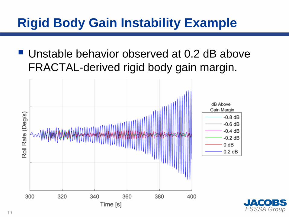
Rigid Body Gain Instability Example
10
Unstable behavior observed at 0.2 dB above
FRACTAL-derived rigid body gain margin.

Rigid Body Gain Margin Assessments
11
Margins evaluated at
80, 140, and 300
seconds.
FRACTAL-derived
margins are consistently
verified in the time
domain (with the
exception of 300
seconds in pitch/yaw).

Phase Margin Assessments
12
Error bars to show
ambiguity associated
with phase margin
identification.
System is consistently
stable beyond baseline
margins derived in
FRACTAL after 100
seconds.

Aero Gain Margin Assessments
13
Only evaluated at 300
seconds.
Requires significant
time (at least 100-200
seconds) for instability
to show in the time
domain.

Summary
14
The gain and phase in the time domain were
artificially adjusted relative to the margins derived
in the frequency domain until unstable behavior
was observed via divergent body rates.
Time domain gain margins matched frequency
domain margins well (with a few exceptions).
Phase margins were consistently higher in the
time domain.
This method can be applied to adaptive
controllers and any time-varying nonlinear effects
not captured in frequency domain analysis.

Backup
15

Rigid Body Gain Instability Example
16

Rigid Body Gain Instability Example
17

Effects of Slosh
18
The slosh damping values used in the FRACTAL
frequency domain were based on the requirement
damping profile at a fixed wave height of 4”.
In the full 6-dof time-domain MAVERIC
simulations, the slosh damping follows a nonlinear
slosh damping model that is a function of wave
height.
This leads to more stable simulations in the
presence of rigid body gain instabilities when
slosh is the driving factor behind the gain margin.

Effects of Slosh
19
As the gain is increased, the wave height is
increased. This leads to increased damping and
therefore a more stable vehicle.
When slosh drives the gain margin, the gain must
be increased beyond the point of being slosh
dominated in order to display an instability.Slosh-dominated Rigid-body dominated

Significant Finding - Frozen Guidance
20
Closed-loop guidance destabilized before the
controller when testing aero gain margins.
Results in 3-5 dB of low-frequency gain margin
degradation in the full closed-loop GNC simulation.
Frozen Guidance Regular Guidance


