This tutorial describes the steps to constrain and perform static timing analysis with the TimeQuest Timing Analyzer. For this tutorial, use the fir_filter design that ships with the Quartus® II software. Figure 1–1 shows the fir_filter design schematic.
System RequirementsFor this tutorial, use Stratix, Cyclone, MAX II, or newer device families (you can also use MAX 3000 and MAX 7000 device families) with the Quartus® II software beginning with version 6.0. APEX, FLEX, and Mercury device families are not supported.
ProceduresUse the following steps to constrain and analyze a design with the TimeQuest Timing Analyzer. Each step includes the GUI procedure and the command-line equivalent.
Step 1: Open and Setup Your Design in the Quartus II SoftwareIn the Quartus II software, browse to and open the fir_filter located in the <qdesign folder>/fir_filter/ folder. Use the GUI or the command-line equivalent procedures in Table 2–1.
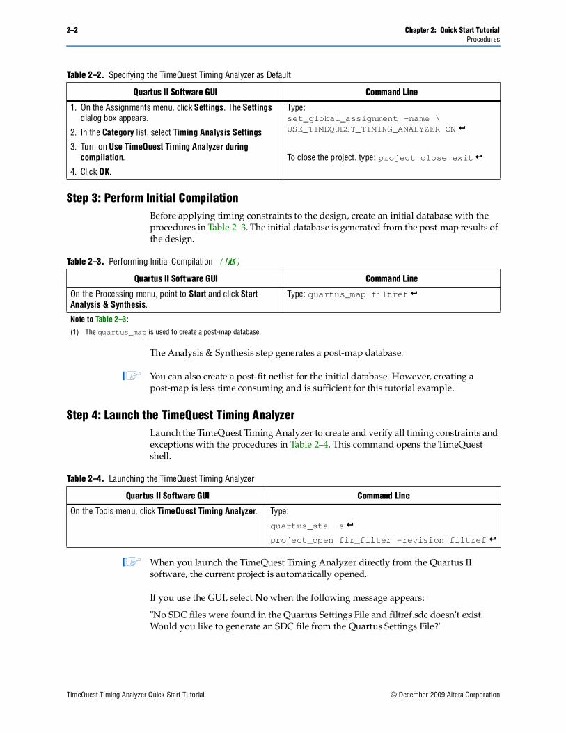
Step 2: Setup the TimeQuest Timing AnalyzerBy default, the Quartus II software uses the Classic Timing Analyzer as the timing analysis tool for designs targeting the Cyclone device family. Specify the TimeQuest Timing Analyzer as the timing analysis tool in the Quartus II software to use in the compilation flow for the fir_filter project.
1 This step is not required for all projects. The newer FPGA families default to the TimeQuest Timing Analyzer.
Specify the TimeQuest Timing Analyzer as the timing analysis tool in the Quartus II software with the procedures in Table 2–2.
Table 2–1. Opening and Setting Up Your Design
Quartus II Software GUI Command Line
On the File menu, click Open Project and browse to the project file <Quartus II Installation Folder>\qdesigns\fir_filter\fir_filter.qpf.
Type:
quartus_sh –s rproject_open fir_filter -revision \ filtref r
Step 3: Perform Initial CompilationBefore applying timing constraints to the design, create an initial database with the procedures in Table 2–3. The initial database is generated from the post-map results of the design.
The Analysis & Synthesis step generates a post-map database.
1 You can also create a post-fit netlist for the initial database. However, creating a post-map is less time consuming and is sufficient for this tutorial example.
Step 4: Launch the TimeQuest Timing AnalyzerLaunch the TimeQuest Timing Analyzer to create and verify all timing constraints and exceptions with the procedures in Table 2–4. This command opens the TimeQuest shell.
1 When you launch the TimeQuest Timing Analyzer directly from the Quartus II software, the current project is automatically opened.
If you use the GUI, select No when the following message appears:
"No SDC files were found in the Quartus Settings File and filtref.sdc doesn't exist. Would you like to generate an SDC file from the Quartus Settings File?"
Table 2–2. Specifying the TimeQuest Timing Analyzer as Default
Quartus II Software GUI Command Line
1. On the Assignments menu, click Settings. The Settings dialog box appears.
2. In the Category list, select Timing Analysis Settings
3. Turn on Use TimeQuest Timing Analyzer during compilation.
4. Click OK.
Type:set_global_assignment -name \ USE_TIMEQUEST_TIMING_ANALYZER ON r
Step 5: Create a Post-Map Timing NetlistBefore specifying the timing requirements, create a timing netlist. You can create a timing netlist from a post-map or post-fit database. In this step, create a timing netlist from the post-map database you created in “Step 3: Perform Initial Compilation” with the procedures in Table 2–5.
1 You cannot use the Create Timing Netlist command in the Tasks pane to create a post-map timing netlist. By default, the Create Timing Netlist requires a post-fit database.
Step 6: Specify Timing RequirementsYou must define two clocks in the fir_filter design. Refer to Table 2–6 for a list of properties for each clock.
Create the clocks in the fir_filter design and assign the proper clock ports with the procedures in Table 2–7.
f For more information about constraints supported by the TimeQuest Timing Analyzer, refer to the TimeQuest Timing Analyzer chapter in volume 3 of the Quartus II Handbook.
1 By default, the create_clock command assumes a 50/50 duty cycle if the -waveform option is not used.
f For more information about creating clocks of different duty cycles, refer to the TimeQuest Timing Analyzer chapter in volume 3 of the Quartus II Handbook.
After you complete the procedure shown in Table 2–7, the clock definition is complete.
Step 7: Update the Timing NetlistAfter you create timing constraints or exceptions, update the timing netlist to apply all timing requirements to the timing netlist (the new clk and clkx2 clock constraints) with the procedures in Table 2–8.
1 You must update the timing netlist whenever new timing constraints are applied.
Step 8: Save the Synopsys Design Constraints (SDC) FileYou have the option of creating an SDC file after specifying the clock constraints for the design and updating the timing netlist with the procedures in Table 2–9. Constraints that have been specified with the TimeQuest Timing Analyzer GUI or in the console are not automatically saved.
1 If you inadvertently overwrite any of your constraints later in the design flow, use this initial SDC file to restore all of your constraints.
The initial SDC file can act as the “golden” SDC file that contains the original constraints and exceptions for the design.
The new filtref.sdc file contains the constraints and false path exceptions for the two clocks that you defined in “Step 6: Specify Timing Requirements”.
The Write SDC File command can overwrite any existing SDC file. When this occurs, the new SDC file does not maintain order or comments. Therefore, Altera recommends saving a golden SDC file separately that you can manually edit with a text editor. This allows you to enter comments and organize the file to your own specifications.
Step 9: Generate Timing Reports for the Initial Timing NetlistAfter specifying timing constraints and updating the timing netlist, generate timing reports, which verify that all clocks are properly defined and applied to the correct nodes, for the two clocks you defined with the procedures in Table 2–10. The TimeQuest Timing Analyzer provides easy to use report generation commands that allow you to verify all timing requirements in the design.
Figure 2–1 shows the Create Clock report that you generate when you click Report SDC in the Tasks pane.
SDC Assignments reports all timing constraints and exceptions specified in the design. Two reports are generated: one for the clocks and one for the clock groups.
Generate a report that summarizes all clocks in the design with the procedures in Table 2–11.
Figure 2–2 shows the Clocks Summary report.
Use the Report Clock Transfers command to generate a report to verify that all clock-to-clock transfers are valid with the procedures in Table 2–12. This report contains all clock-to-clock transfers in the design.
The Clock Transfers report indicates that a clock-to-clock transfer exists between the clk source and the clkx2 destination. There are 16 instances where clk clocks the source node and where clkx2 clocks the destination node.
In the fir_filter design, you do not have to analyze clock transfers from clk to clkx2 because they are false paths. Declare the paths from clk to clkx2 as false paths with the procedures in Table 2–13. When you complete this procedure, the TimeQuest Timing Analyzer indicates that the Clock Transfers report is outdated.
1 Alternatively, use the set_clock_groups command to declare the paths between the two clock domains as false paths. For example, set_clock_groups -asynchronous -group [get_clocks clk] -group [get_clocks clkx2]. This command declares all paths from clk to clkx2 and from clkx2 to clk as false paths. This method is preferred.
Because you have added a new timing constraint, update the timing netlist with the procedure in Table 2–14.
1. In the Clock Transfers report, select clk in the From Clock column.
2. Right-click and select Set False Paths Between Clock Domains. This command declares all paths from registers clocked by clk to registers clocked by clkx2 as false paths.
Type:
set_false_path -from [get_clocks clk] \-to [get_clocks clkx2] r
After you enter the set_false_path in the GUI, all generated report panels are labeled “Out of Date,” indicating that the report panels do not contain results that reflects the current state of constraints or exceptions in the TimeQuest Timing Analyzer. To update the report panels, you must regenerate all of the reports.
At the command-line, re-enter the commands. In the GUI, right-click on any out-of-date report in the report panel list and select Regenerate or Regenerate all.
After you update the timing netlist, verify that the clock-to-clock transfer has been declared false with the procedures in Table 2–15.
Figure 2–4 shows the new SDC Assignments report.
The report shown in Figure 2–4 indicates that the clock constraints and the false paths are correct.
Use the Report Clocks and Report Clock Transfers commands to verify that the two clocks have been removed from analysis. Figure 2–5 shows the Clock Transfers report.
f The RR Paths column contains the comment “false path” to indicate that you have declared the clock domains as false paths.
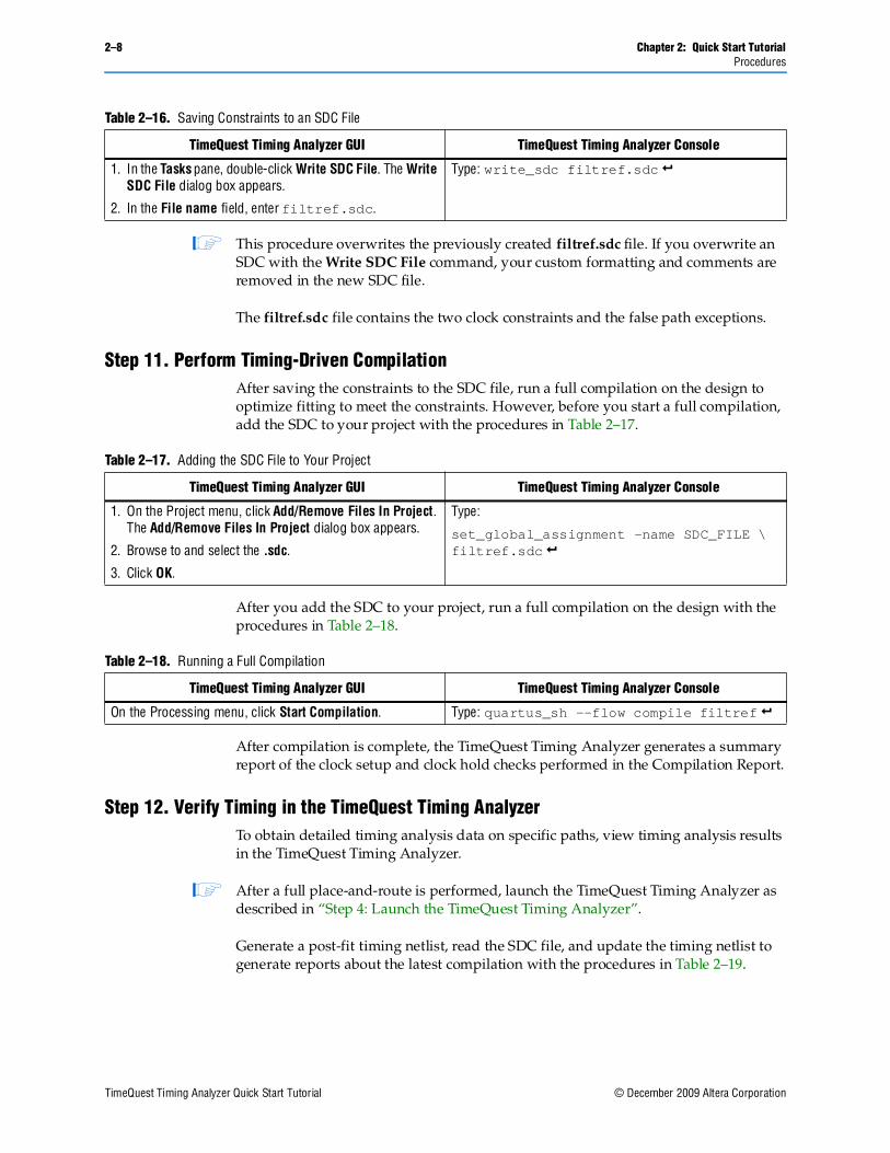
Step 10: Save Constraints to an SDC FileAfter you specify all clock constraints and false paths for the design, save the timing constraints and exceptions to an SDC file with the procedures in Table 2–16.
Table 2–15. Verifying Using the Report SDC Command
1 This procedure overwrites the previously created filtref.sdc file. If you overwrite an SDC with the Write SDC File command, your custom formatting and comments are removed in the new SDC file.
The filtref.sdc file contains the two clock constraints and the false path exceptions.
Step 11. Perform Timing-Driven CompilationAfter saving the constraints to the SDC file, run a full compilation on the design to optimize fitting to meet the constraints. However, before you start a full compilation, add the SDC to your project with the procedures in Table 2–17.
After you add the SDC to your project, run a full compilation on the design with the procedures in Table 2–18.
After compilation is complete, the TimeQuest Timing Analyzer generates a summary report of the clock setup and clock hold checks performed in the Compilation Report.
Step 12. Verify Timing in the TimeQuest Timing AnalyzerTo obtain detailed timing analysis data on specific paths, view timing analysis results in the TimeQuest Timing Analyzer.
1 After a full place-and-route is performed, launch the TimeQuest Timing Analyzer as described in “Step 4: Launch the TimeQuest Timing Analyzer”.
Generate a post-fit timing netlist, read the SDC file, and update the timing netlist to generate reports about the latest compilation with the procedures in Table 2–19.
1 When you double-click one of the reporting commands, the Create Timing Netlist, Read SDC, and Update Timing Netlist commands are sequentially executed in the Tasks pane, automatically setting up the timing netlist.
The clock setup check ensures that each register-to-register transfer does not violate the timing constraints you specified in the SDC. Verify that no violations have occurred by generating a clock setup summary check for all clocks in the design with the procedures in Table 2–20.
Figure 2–6 shows the Summary (Setup) report.
1 The clkx2 clock does not appear in the Summary (Setup) report because all clock paths between clk and clkx2 have been declared as false paths. In addition, the fir_filter design does not contain any register-to-register paths where a destination register path is clocked by clkx2.
The Slack column in the Summary (Setup) report indicates that clk fails to meet the constraint by 11.588 ns. The End Point TNS column is the total of all total negative slack (TNS) for the specified clock domain. Use this value to gauge the amount of failing paths in the specified clock domain.
1 For the fir_filter design, the Slack column equals the End Point TNS, indicating that there is only one failing path for the clk clock domain.
Table 2–19. Generating Reports About the Latest Compilation
After you generate the Summary (Setup) report, generate a clock hold check summary for the design with the procedures in Table 2–21.
Figure 2–7 shows the Summary (Hold) report.
The Summary (Hold) report indicates that the clk clock node meets the timing constraints by 0.661 ns.
Specify all timing constraints and exceptions prior to performing a full compilation with the procedures in Table 2–22. This ensures that the Fitter optimizes for the critical paths in the design.
You can use the Report Unconstrained Paths command to verify that you have constrained all paths in the fir_filter design.
Figure 2–8 shows the Unconstrained Paths Summary report.
The Unconstrained Paths Summary report indicates that there are numerous unconstrained paths and details the types of paths.
To fully constrain this design, utilize the full set of SDC constraints provided by the TimeQuest Timing Analyzer.
To fully constrain the fir_filter design, constrain all input and output ports. Use the Set Input Delay and Set Output Delay dialog boxes, or the set_input_delay and set_output_delay constraints to specify the input and output delay values.
Because additional constraints are applied to the design, create an additional SDC that contains only the input and output constraints with the text editor (for example, inout_delay.sdc). Add the input and output delay assignments shown in Table 2–23 to the new SDC created in “Step 10: Save Constraints to an SDC File”.
All ports should be constrained in the design after you read the SDC containing the input and output delay constraints.
1 Remember to update the timing netlist after reading the new constraints. For more information, refer to “Step 7: Update the Timing Netlist”.
To verify all ports are constrained in the design, regenerate the Unconstrained Paths Summary report (Figure 2–9).
Generate specific timing check reports for clocks or nodes in the design with the procedures in Table 2–24. The procedures in Table 2–24 generate a report where clk clocks the destination register to the design destination register bus acc:inst3|result and reports the top 10 worst paths.
Table 2–23. Input and Output Delay Assignments
The TimeQuest Timing Analyzer GUI The TimeQuest Timing Analyzer Console
1. On the Constraints menu, click Set Input Delay. The Set Input Delay dialog box appears.
2. Enter the following:Clock name: clkDelay value: 2Targets: [get_ports {d[0] d[1] d[2] d[3] \d[4] d[5] d[6] d[7] newt reset}]
3. On the Constraints menu, click Set Output Delay. The Set Output Delay dialog box appears.
4. Enter the following:Clock name: clkDelay value: 1.5Targets: [get_ports {yn_out[0] yn_out[1] \yn_out[2] yn_out[3] yn_out[4] yn_out[5] \yn_out[6] yn_out[7] yvalid follow}]
To constrain the input ports, type:
set_input_delay -clock clk 2 \[get_ports {d* newt reset}] r
To constrain the output ports, type:
set_output_delay -clock clk 1.5 \[get_ports {yn_out* yvalid follow}] r
Use the Report Top Failing Paths command in the Tasks pane to generate a report that details the top failing paths in the design.
ConclusionAs you create new constraints or exceptions, rerun the Quartus II Fitter to optimize the design based on your new constraints or exceptions. Multiple iterations on the design may be necessary to achieve the desired results.
Commands and Tcl ScriptsThis section includes commands and accompanying Tcl scripts to execute the entire flow from the command line. Use this method to completely execute the entire flow.
Enter the command in Example 3–1 at a command prompt to source the scripts.
Example 3–2 shows the content of the timequest_setup.tcl script. Use this script to specify the TimeQuest Timing Analyzer as the default timing analysis tool.
1 The Classic Timing Analyzer is the default timing analyzer in the Quartus II software.
Example 3–3 shows the content of the main_postmap.tcl script. Use this script to create post-map data, set up the timing netlist, read in golden.sdc, and generate initial reports for the design.
#open the filtref projectproject_open filtref r#set the TimeQuest analyzer as the default timing analyzerset_global_assignment -name USE_TIMEQUEST_TIMING_ANALYZER ON r#close the projectproject_close r
3–2 Chapter 3: Script ExamplesCommands and Tcl Scripts
Example 3–4 shows the content of the fit_sdc_setup.tcl script. Use this script to add the golden.sdc file to the filtref design. This allows the Quartus II Fitter to optimize the design according to the constraints you specify.
Example 3–5 shows the content of the main_postfit.tcl script. Use this script to create a post-fit database, set up the timing netlist, read in the golden.sdc and io_cons.sdc files, and generate reports for the design.
Example 3–3. The main_postmap.tcl Script
#file main_postmap.tcl#Include the flow package to create a post-map netlistpackage require ::quartus::flow r#open the project in TimeQuestproject_open filtref r#create a post-map databaseexecute_module -tool map r#create the timing netlist based on the post-map resultscreate_timing_netlist -post_map r#read in the constraints from the golden SDC fileread_sdc golden.sdc r#update the timing netlist with the new constraintsupdate_timing_netlist r#generated a clock reportreport_clocks r#generated a clock-to-clock reportreport_clock_transfers r#delete our post-map timing netlistdelete_timing_netlist r#close the TimeQuest projectproject_close r
Example 3–4. The fit_sdc_setup.tcl Script
#open the filtref projectproject_open filtref r#add the filtref.sdc file to our Quartus II projectset_global_assignment -name SDC_FILE golden.sdc r#close the projectproject_close r
Chapter 3: Script Examples 3–3Commands and Tcl Scripts
Example 3–6 and Example 3–7 show the contents of the golden.sdc and io_cons.sdc files, respectively.
Example 3–5. The main_postfit.tcl Script
#Include the flow package to create a post-fit netlistpackage require ::quartus::flow r#open the project in TimeQuestproject_open filtref r#create a post-fit databaseexecute_module -tool fit r#create a post-fit timing netlistcreate_timing_netlist r#read the golden SDC file and the I/O SDC fileread_sdc golden.sdc rread_sdc io_cons.sdc r#update the post-fit timing netlist with constraintsupdate_timing_netlist r#report unconstrained pathsreport_clocks rcreate_timing_summary -setup rcreate_timing_summary -hold rcreate_timing_summary -recovery rcreate_timing_summary -removal rreport_ucp r#delete our post-map timing netlistdelete_timing_netlist r#close the TimeQuest projectproject_close r
Example 3–6. The golden.sdc File
#create the 50 MHz 50/50 clockcreate_clock –period 20 [get_ports clk] r#create the 100 MHz 60/40 clockcreate_clock –period 10 –waveform {0 6} [get_ports clkx2] r#cut the clk and clkx2 domainsset_clock_groups -group [get_clocks clk] -group [get_clocks clkx2] r
Example 3–7. The io_cons.sdc File
#set the input delays for the designset_input_delay -clock clk 1.0 [get_ports {d[*] reset newt}] r#set the output delays for the designset_output_delay -clock clk 1.5 [get_ports {yn_out[0] yn_out[1] \yn_out[2] yn_out[3] yn_out[4] yn_out[5] yn_out[6] yn_out[7] yvalid follow}] r
3–4 Chapter 3: Script ExamplesCommands and Tcl Scripts
(1) You can also contact your local Altera sales office or sales representative.
Visual Cue Meaning
Bold Type with Initial Capital Let-ters
Command names, dialog box titles, checkbox options, and dialog box options are shown in bold, initial capital letters. Example: Save As dialog box.
bold type External timing parameters, directory names, project names, disk drive names, file names, file name extensions, and software utility names are shown in bold type. Examples: fMAX, \qdesigns directory, d: drive, chiptrip.gdf file.
Italic Type with Initial Capital Letters Document titles are shown in italic type with initial capital letters. Example: AN 75: High-Speed Board Design.
Italic type Internal timing parameters and variables are shown in italic type.
Examples: tPIA, n + 1.
Variable names are enclosed in angle brackets (< >) and shown in italic type. Example: <file name>, <project name>.pof file.
Initial Capital Letters Keyboard keys and menu names are shown with initial capital letters. Examples: Delete key, the Options menu.
“Subheading Title” References to sections within a document and titles of on-line help topics are shown in quotation marks. Example: “Typographic Conventions.”
Courier type Signal and port names are shown in lowercase Courier type. Examples: data1, tdi, input. Active-low signals are denoted by suffix n, e.g., resetn.
Anything that must be typed exactly as it appears is shown in Courier type. For exam-ple: c:\qdesigns\tutorial\chiptrip.gdf. Also, sections of an actual file, such as a Report File, references to parts of files (e.g., the AHDL keyword SUBDE-SIGN), as well as logic function names (e.g., TRI) are shown in Courier.
1., 2., 3., anda., b., c., etc.
Numbered steps are used in a list of items when the sequence of the items is impor-tant, such as the steps listed in a procedure.
■ ■ Bullets are used in a list of items when the sequence of the items is not important.
v The checkmark indicates a procedure that consists of one step only.
1 The hand points to information that requires special attention.
c A caution calls attention to a condition or possible situation that can damage or destroy the product or the user’s work.
w A warning calls attention to a condition or possible situation that can cause injury to the user.
r The angled arrow indicates you should press the Enter key.
f The feet direct you to more information on a particular topic.