Page 1
© D
ASS
AU
LT S
YS
TEM
ES S
.A. 2
000
2000-02 page 2
F&A Hints and TipsF&A Hints and Tips
1 - Fundamentals• Sketcher• Wireframe & Surfaces• Part• Assembly• Drafting
2 - Reminders• Common Tools
Page 2
© D
ASS
AU
LT S
YS
TEM
ES S
.A. 2
000
2000-02 page 3
F&A Hints and Tips - SketcherF&A Hints and Tips - Sketcher
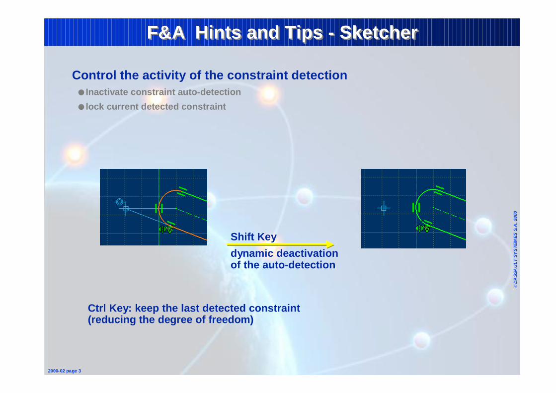
Control the activity of the constraint detection● Inactivate constraint auto-detection
● lock current detected constraint
Shift Key
dynamic deactivation of the auto-detection
Ctrl Key: keep the last detected constraint (reducing the degree of freedom)
Page 3
© D
ASS
AU
LT S
YS
TEM
ES S
.A. 2
000
2000-02 page 4
F&A Hints and Tips - SketcherF&A Hints and Tips - Sketcher
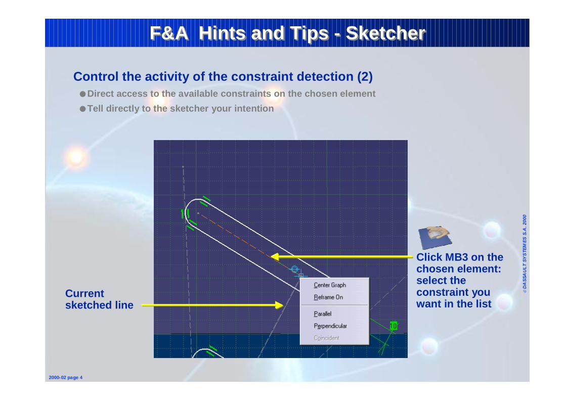
Control the activity of the constraint detection (2)● Direct access to the available constraints on the chosen element
● Tell directly to the sketcher your intention
Current sketched line
Click MB3 on the chosen element: select the constraint you want in the list
Page 4
© D
ASS
AU
LT S
YS
TEM
ES S
.A. 2
000
2000-02 page 5
F&A Hints and Tips - SketcherF&A Hints and Tips - Sketcher
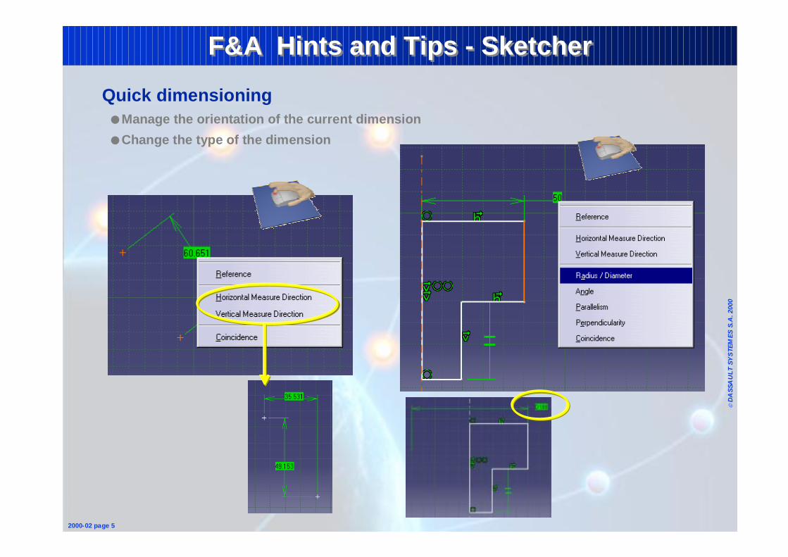
Quick dimensioning● Manage the orientation of the current dimension
● Change the type of the dimension
Page 5
© D
ASS
AU
LT S
YS
TEM
ES S
.A. 2
000
2000-02 page 6
F&A Hints and Tips - SketcherF&A Hints and Tips - Sketcher
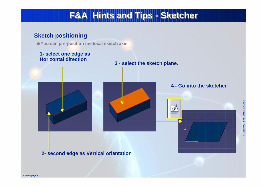
Sketch positioning ● You can pre-position the local sketch axis
1- select one edge as Horizontal direction
2- second edge as Vertical orientation
3 - select the sketch plane.
4 - Go into the sketcher
Page 6
© D
ASS
AU
LT S
YS
TEM
ES S
.A. 2
000
2000-02 page 7
F&A Hints and Tips - SketcherF&A Hints and Tips - Sketcher
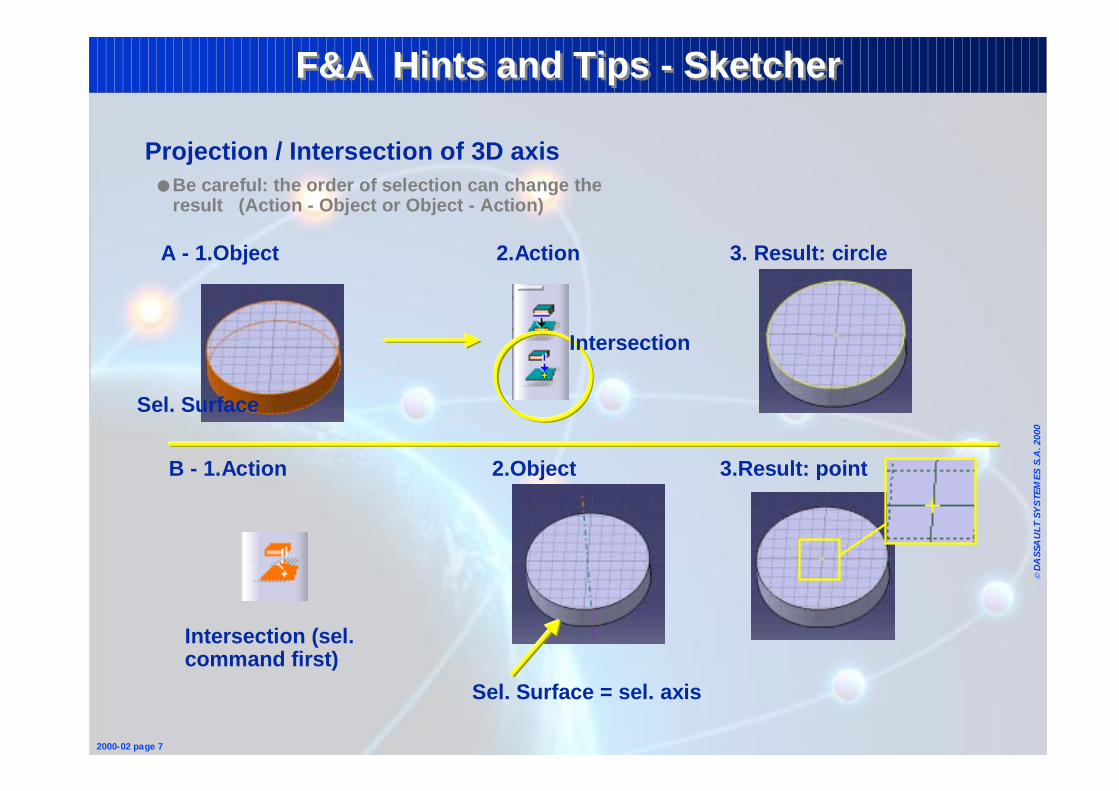
Projection / Intersection of 3D axis● Be careful: the order of selection can change the
result (Action - Object or Object - Action)
B - 1.Action 2.Object 3.Result: point
A - 1.Object 2.Action 3. Result: circle
Intersection (sel. command first)
Sel. Surface = sel. axis
Intersection
Sel. Surface
Page 7
© D
ASS
AU
LT S
YS
TEM
ES S
.A. 2
000
2000-02 page 8
F&A Hints and Tips - SketcherF&A Hints and Tips - Sketcher
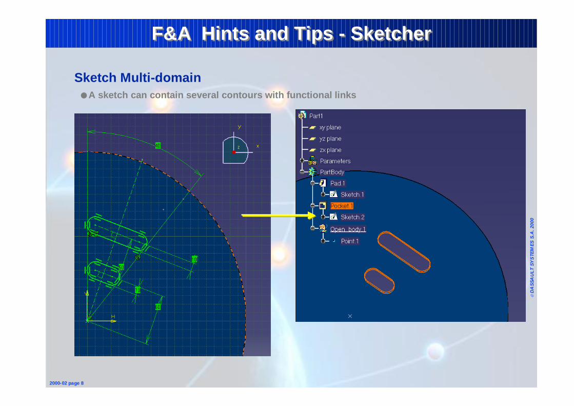
Sketch Multi-domain● A sketch can contain several contours with functional links
Page 8
© D
ASS
AU
LT S
YS
TEM
ES S
.A. 2
000
2000-02 page 9
F&A Hints and TipsF&A Hints and Tips
1 - Fundamentals• Sketcher• Wireframe & Surfaces• Part• Assembly• Drafting
2 - Reminders• Common Tools
Page 9
© D
ASS
AU
LT S
YS
TEM
ES S
.A. 2
000
2000-02 page 10
F&A Hints and Tips - WireframeF&A Hints and Tips - Wireframe
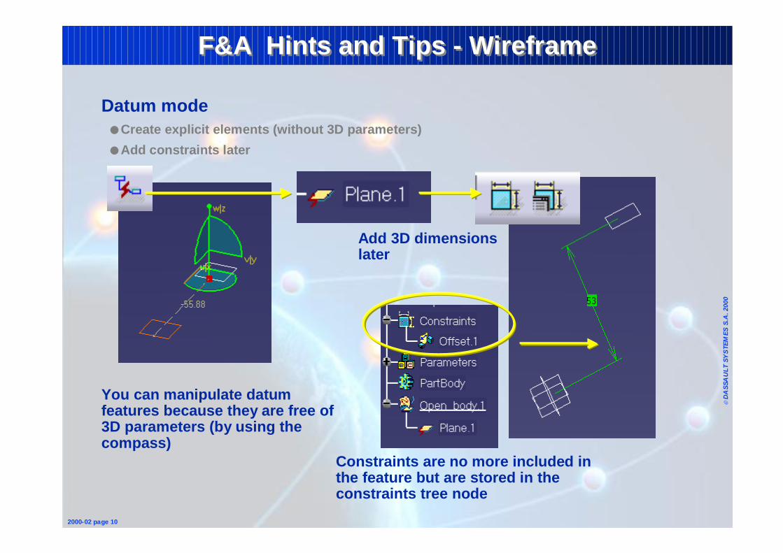
Datum mode ● Create explicit elements (without 3D parameters)
● Add constraints later
Constraints are no more included in the feature but are stored in the constraints tree node
Add 3D dimensions later
You can manipulate datum features because they are free of 3D parameters (by using the compass)
Page 10
© D
ASS
AU
LT S
YS
TEM
ES S
.A. 2
000
2000-02 page 11
F&A Hints and Tips - WireframeF&A Hints and Tips - Wireframe
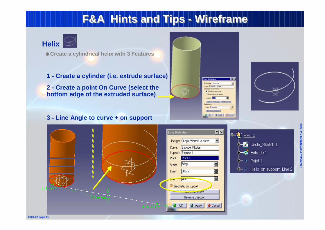
Helix● Create a cylindrical helix with 3 Features
1 - Create a cylinder (i.e. extrude surface)
2 - Create a point On Curve (select the bottom edge of the extruded surface)
3 - Line Angle to curve + on support
Page 11
© D
ASS
AU
LT S
YS
TEM
ES S
.A. 2
000
2000-02 page 12
F&A Hints and Tips - WireframeF&A Hints and Tips - Wireframe
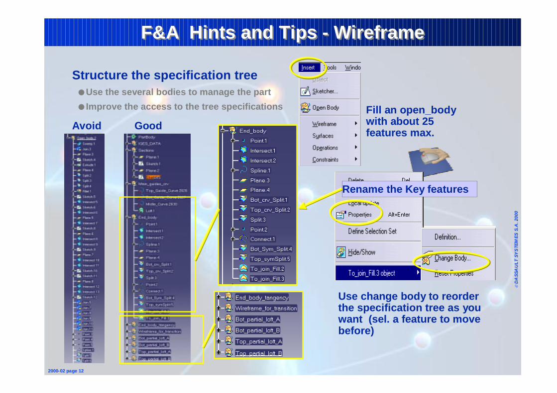
Structure the specification tree● Use the several bodies to manage the part
● Improve the access to the tree specifications Fill an open_body with about 25 features max.
Use change body to reorder the specification tree as you want (sel. a feature to move before)
Rename the Key features
Avoid Good
Page 12
© D
ASS
AU
LT S
YS
TEM
ES S
.A. 2
000
2000-02 page 13
F&A Hints and TipsF&A Hints and Tips
1 - Fundamentals• Sketcher• Wireframe & Surfaces• Part• Assembly• Drafting
2 - Reminders• Common Tools
Page 13
© D
ASS
AU
LT S
YS
TEM
ES S
.A. 2
000
2000-02 page 14
F&A Hints and Tips - PartF&A Hints and Tips - Part
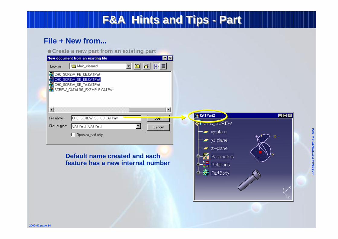
File + New from... ● Create a new part from an existing part
Default name created and each feature has a new internal number
Page 14
© D
ASS
AU
LT S
YS
TEM
ES S
.A. 2
000
2000-02 page 15
F&A Hints and Tips - PartF&A Hints and Tips - Part
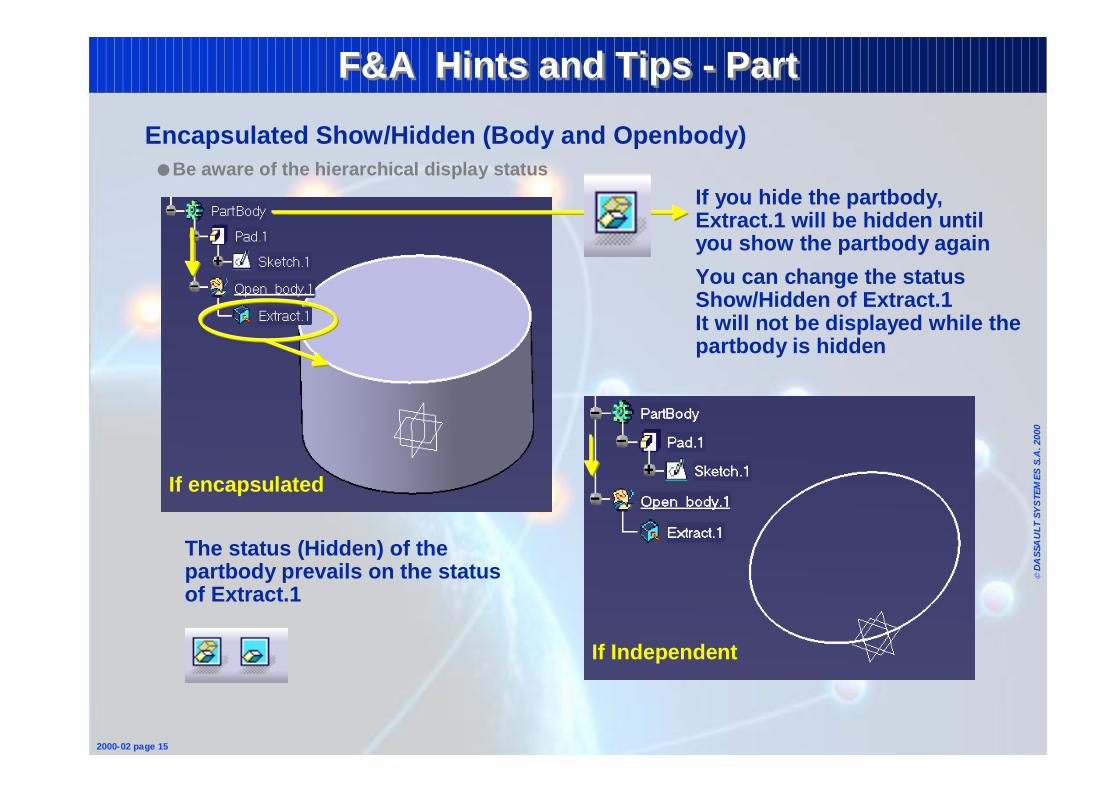
Encapsulated Show/Hidden (Body and Openbody)● Be aware of the hierarchical display status
If you hide the partbody, Extract.1 will be hidden until you show the partbody again
You can change the status Show/Hidden of Extract.1It will not be displayed while the partbody is hidden
The status (Hidden) of the partbody prevails on the status of Extract.1
If encapsulated
If Independent
Page 15
© D
ASS
AU
LT S
YS
TEM
ES S
.A. 2
000
2000-02 page 16
F&A Hints and Tips - PartF&A Hints and Tips - Part
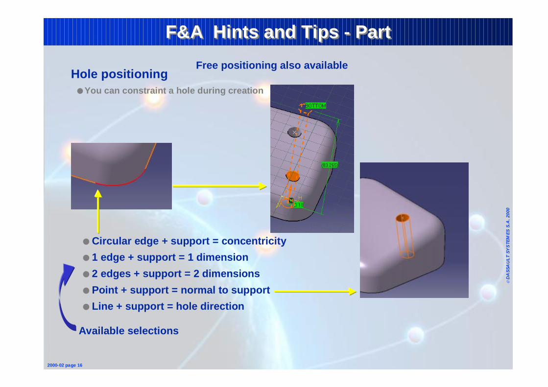
Hole positioning ● You can constraint a hole during creation
● Circular edge + support = concentricity
● 1 edge + support = 1 dimension
● 2 edges + support = 2 dimensions
● Point + support = normal to support
● Line + support = hole direction
Available selections
Free positioning also available
Page 16
© D
ASS
AU
LT S
YS
TEM
ES S
.A. 2
000
2000-02 page 17
F&A Hints and Tips - PartF&A Hints and Tips - Part
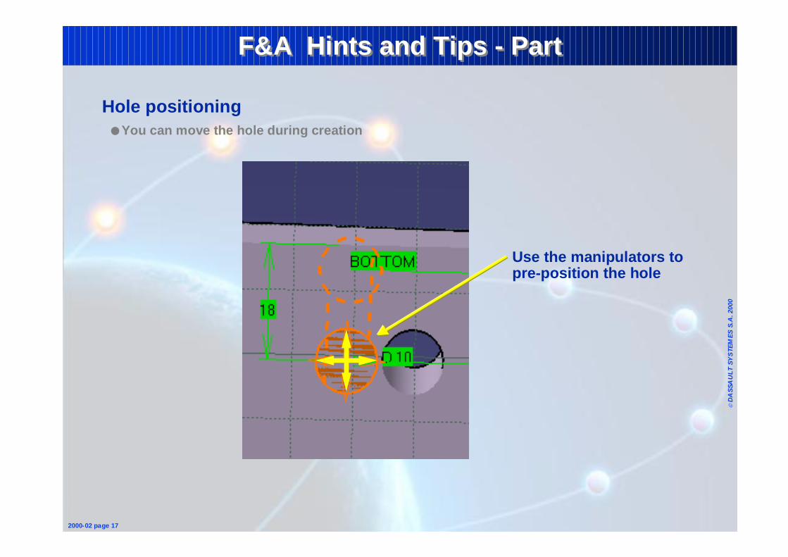
Hole positioning ● You can move the hole during creation
Use the manipulators to pre-position the hole
Page 17
© D
ASS
AU
LT S
YS
TEM
ES S
.A. 2
000
2000-02 page 19
F&A Hints and Tips - PartF&A Hints and Tips - Part
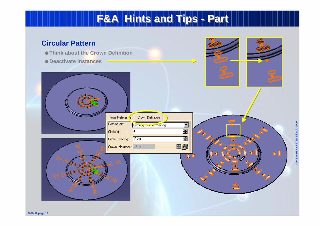
Circular Pattern● Think about the Crown Definition
● Deactivate instances
Page 18
© D
ASS
AU
LT S
YS
TEM
ES S
.A. 2
000
2000-02 page 20
F&A Hints and Tips - PartF&A Hints and Tips - Part
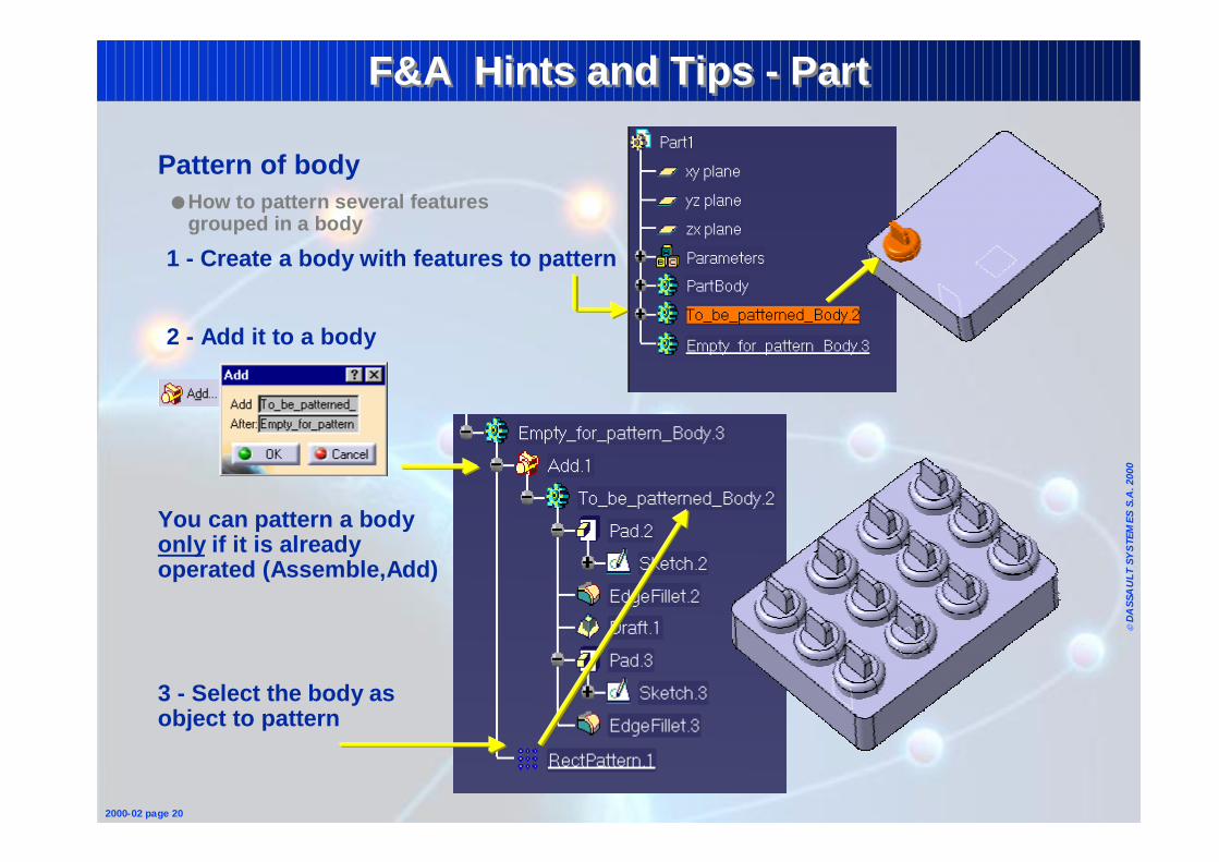
Pattern of body● How to pattern several features
grouped in a body
1 - Create a body with features to pattern
2 - Add it to a body
3 - Select the body as object to pattern
You can pattern a body only if it is already operated (Assemble,Add)
Page 19
© D
ASS
AU
LT S
YS
TEM
ES S
.A. 2
000
2000-02 page 21
F&A Hints and Tips - PartF&A Hints and Tips - Part
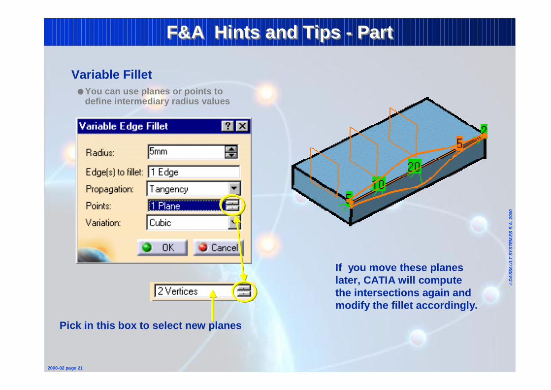
Variable Fillet● You can use planes or points to
define intermediary radius values
Pick in this box to select new planes
If you move these planes later, CATIA will compute the intersections again and modify the fillet accordingly.
Page 20
© D
ASS
AU
LT S
YS
TEM
ES S
.A. 2
000
2000-02 page 22
F&A Hints and Tips - PartF&A Hints and Tips - Part
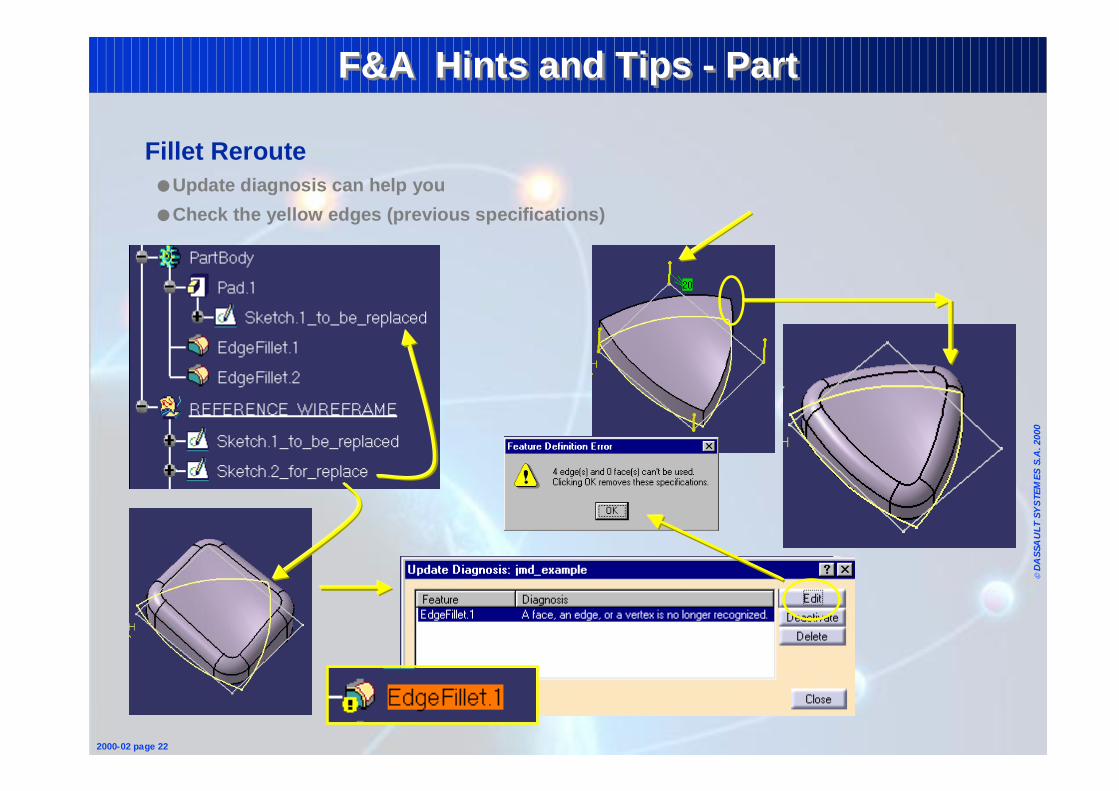
Fillet Reroute ● Update diagnosis can help you
● Check the yellow edges (previous specifications)
Page 21
© D
ASS
AU
LT S
YS
TEM
ES S
.A. 2
000
2000-02 page 23
F&A Hints and Tips - PartF&A Hints and Tips - Part
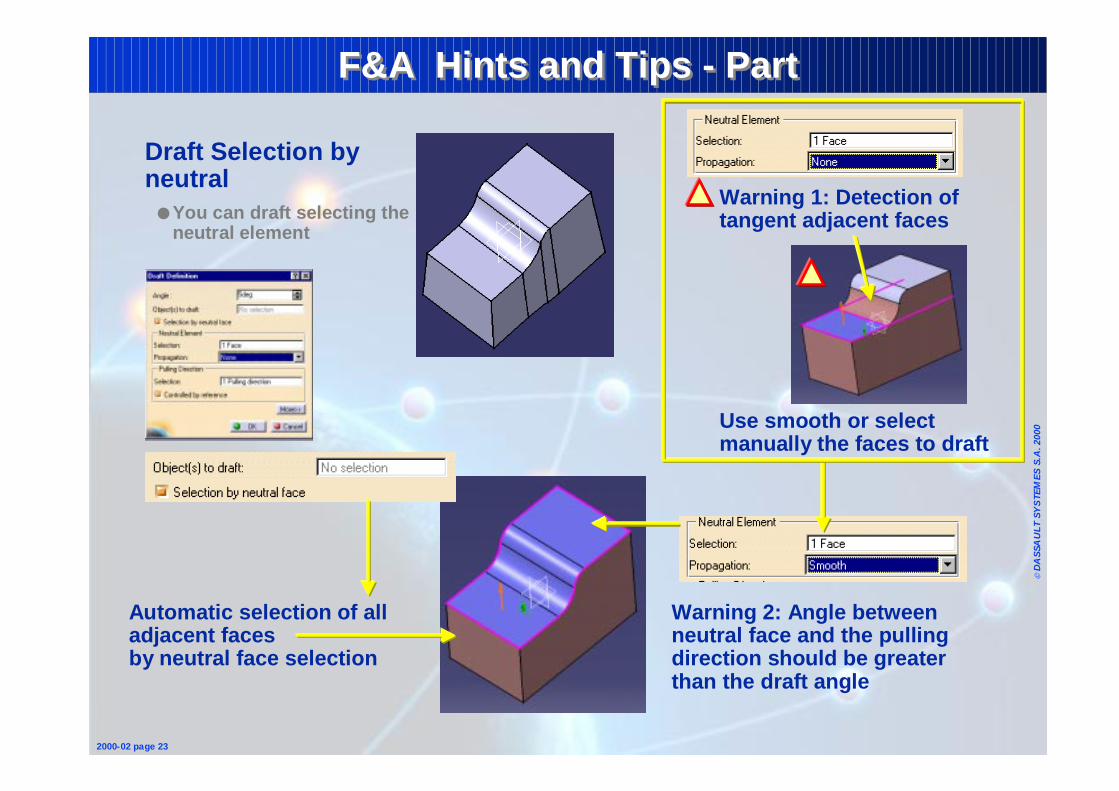
Draft Selection by neutral
● You can draft selecting the neutral element
Warning 1: Detection of tangent adjacent faces
Automatic selection of all adjacent faces by neutral face selection
Warning 2: Angle between neutral face and the pulling direction should be greater than the draft angle
Use smooth or select manually the faces to draft
Page 22
© D
ASS
AU
LT S
YS
TEM
ES S
.A. 2
000
2000-02 page 24
F&A Hints and Tips - PartF&A Hints and Tips - Part
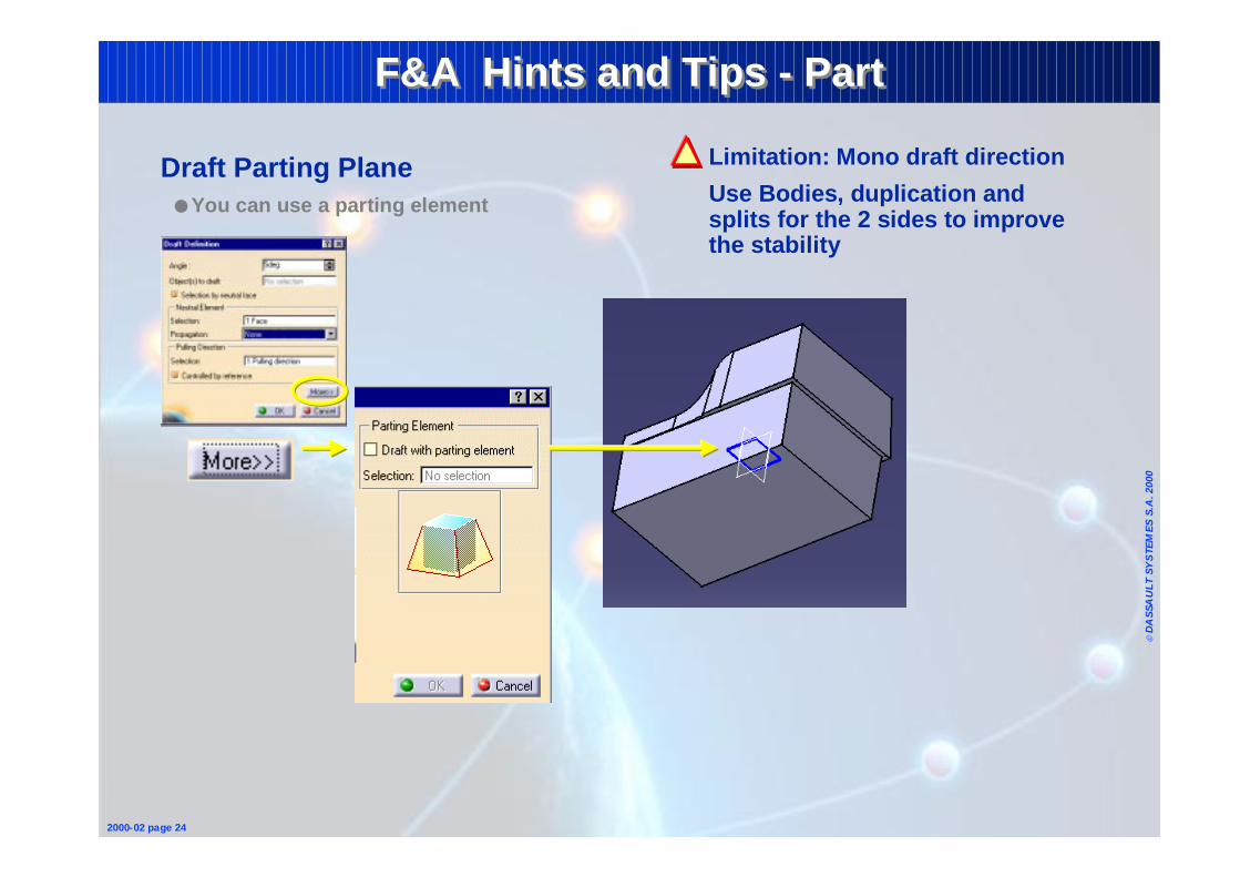
Draft Parting Plane● You can use a parting element
Limitation: Mono draft direction
Use Bodies, duplication and splits for the 2 sides to improve the stability
Page 23
© D
ASS
AU
LT S
YS
TEM
ES S
.A. 2
000
2000-02 page 25
F&A Hints and Tips - PartF&A Hints and Tips - Part
Copy paste as result with link● Create link between 2 parts (i.e. bottle and mold)
1- Copy
2- Paste Special…(new part but could be the same part)
An associative link has been created
3 - Check it with the Edit + Links … or File + Desk... menus
Page 24
© D
ASS
AU
LT S
YS
TEM
ES S
.A. 2
000
2000-02 page 26
F&A Hints and Tips - PartF&A Hints and Tips - Part
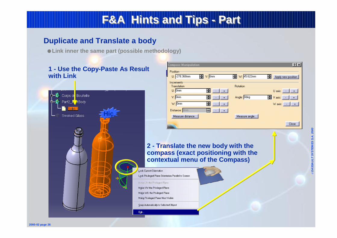
Duplicate and Translate a body● Link inner the same part (possible methodology)
1 - Use the Copy-Paste As Result with Link
Hic
2 - Translate the new body with the compass (exact positioning with the contextual menu of the Compass)
Page 25
© D
ASS
AU
LT S
YS
TEM
ES S
.A. 2
000
2000-02 page 28
F&A Hints and Tips - PartF&A Hints and Tips - Part
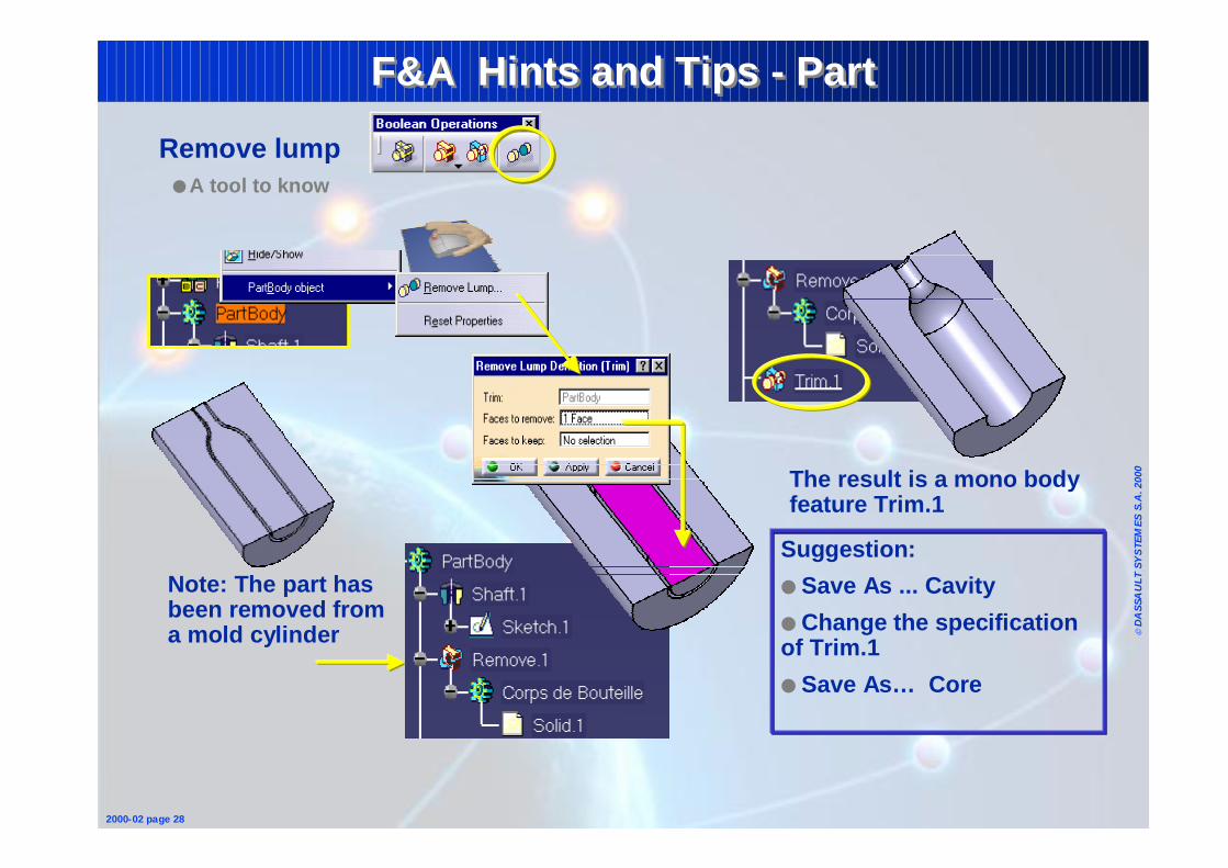
Remove lump● A tool to know
The result is a mono body feature Trim.1
Suggestion:
● Save As ... Cavity
● Change the specification of Trim.1
● Save As… Core
Note: The part has been removed from a mold cylinder
Page 26
© D
ASS
AU
LT S
YS
TEM
ES S
.A. 2
000
2000-02 page 30
F&A Hints and TipsF&A Hints and Tips
1 - Fundamentals• Sketcher• Wireframe & Surfaces• Part• Assembly• Drafting
2 - Reminders• Common Tools
Page 27
© D
ASS
AU
LT S
YS
TEM
ES S
.A. 2
000
2000-02 page 33
F&A Hints and Tips - AssemblyF&A Hints and Tips - Assembly
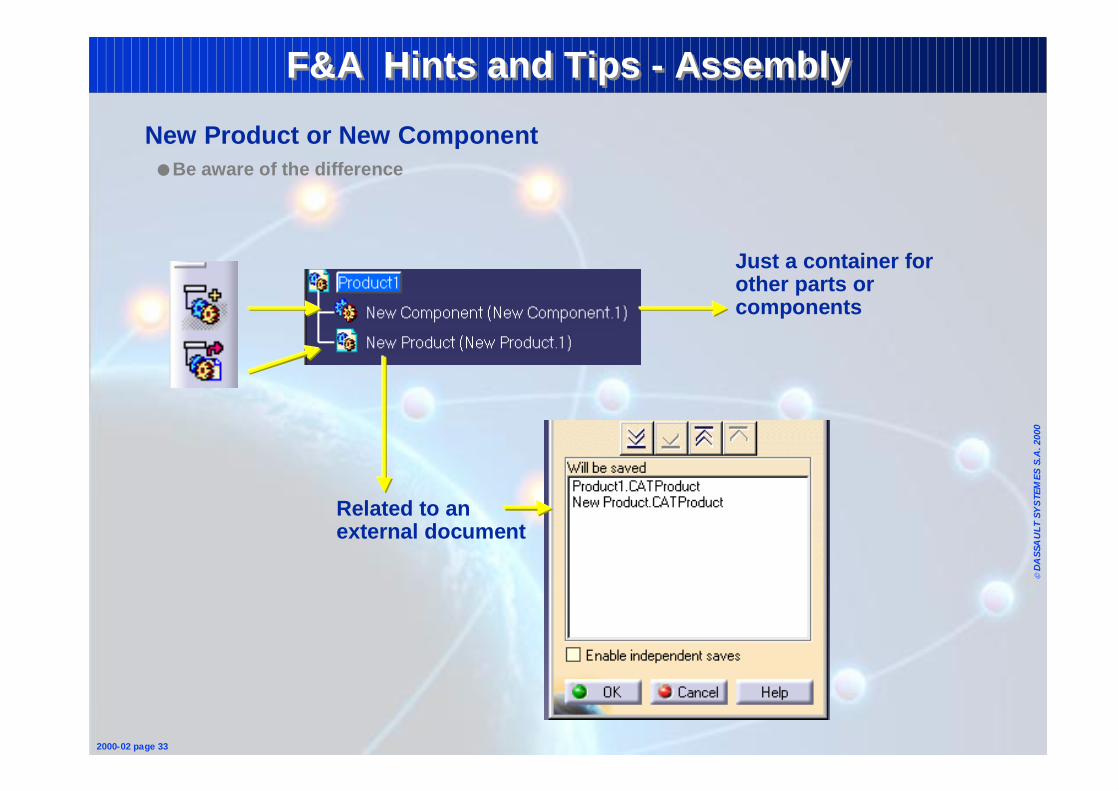
New Product or New Component ● Be aware of the difference
Related to an external document
Just a container for other parts or components
Page 28
© D
ASS
AU
LT S
YS
TEM
ES S
.A. 2
000
2000-02 page 34
F&A Hints and Tips - AssemblyF&A Hints and Tips - Assembly
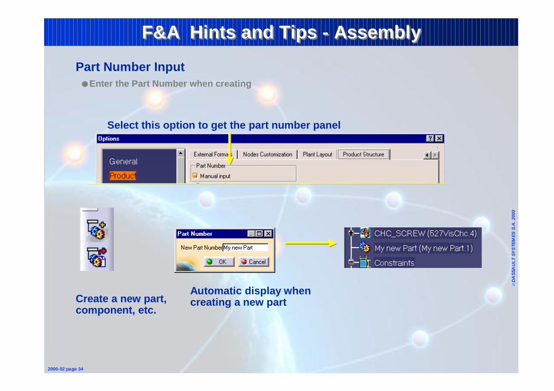
Automatic display when creating a new part
Part Number Input ● Enter the Part Number when creating
Create a new part, component, etc.
Select this option to get the part number panel
Page 29
© D
ASS
AU
LT S
YS
TEM
ES S
.A. 2
000
2000-02 page 35
F&A Hints and Tips - AssemblyF&A Hints and Tips - Assembly
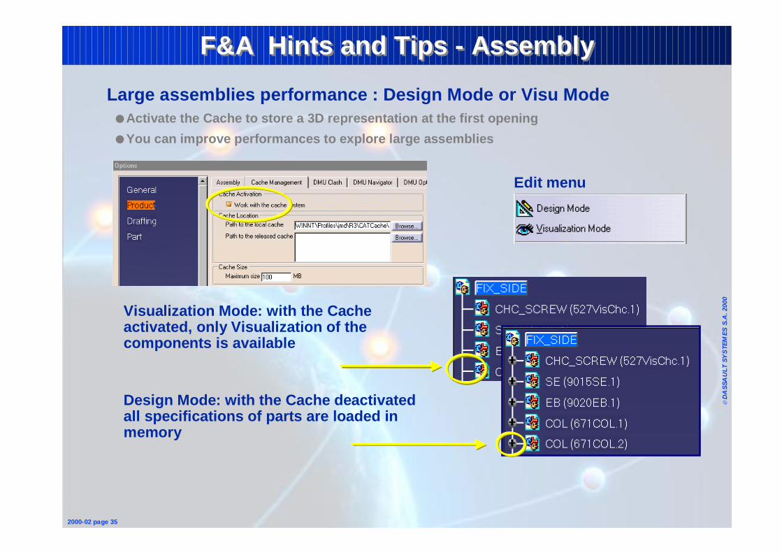
Large assemblies performance : Design Mode or Visu Mode ● Activate the Cache to store a 3D representation at the first opening
● You can improve performances to explore large assemblies
Edit menu
Visualization Mode: with the Cache activated, only Visualization of the components is available
Design Mode: with the Cache deactivated all specifications of parts are loaded in memory
Page 30
© D
ASS
AU
LT S
YS
TEM
ES S
.A. 2
000
2000-02 page 36
F&A Hints and TipsF&A Hints and Tips
1 - Fundamentals• Sketcher• Wireframe & Surfaces• Part• Assembly• Drafting
2 - Reminders• Common Tools
Page 31
© D
ASS
AU
LT S
YS
TEM
ES S
.A. 2
000
2000-02 page 37
F&A Hints and Tips - DraftingF&A Hints and Tips - Drafting
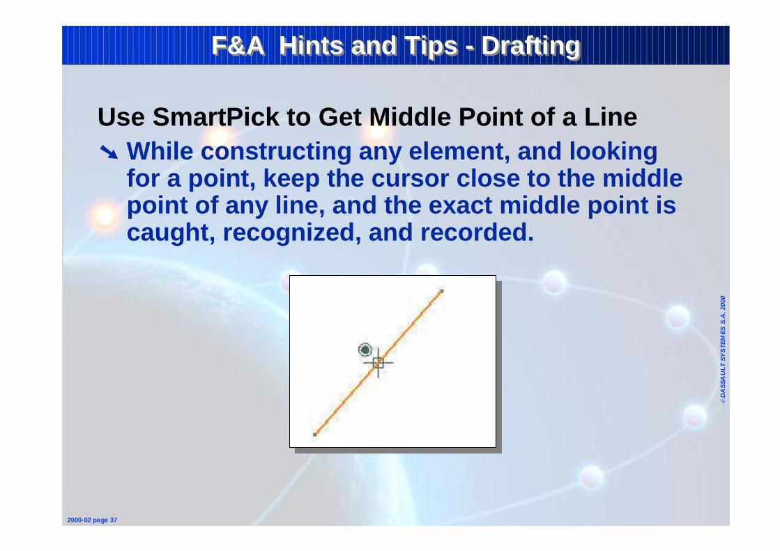
Use SmartPick to Get Middle Point of a Line➘ While constructing any element, and looking
for a point, keep the cursor close to the middle point of any line, and the exact middle point is caught, recognized, and recorded.
Page 32
© D
ASS
AU
LT S
YS
TEM
ES S
.A. 2
000
2000-02 page 38
F&A Hints and Tips - DraftingF&A Hints and Tips - Drafting
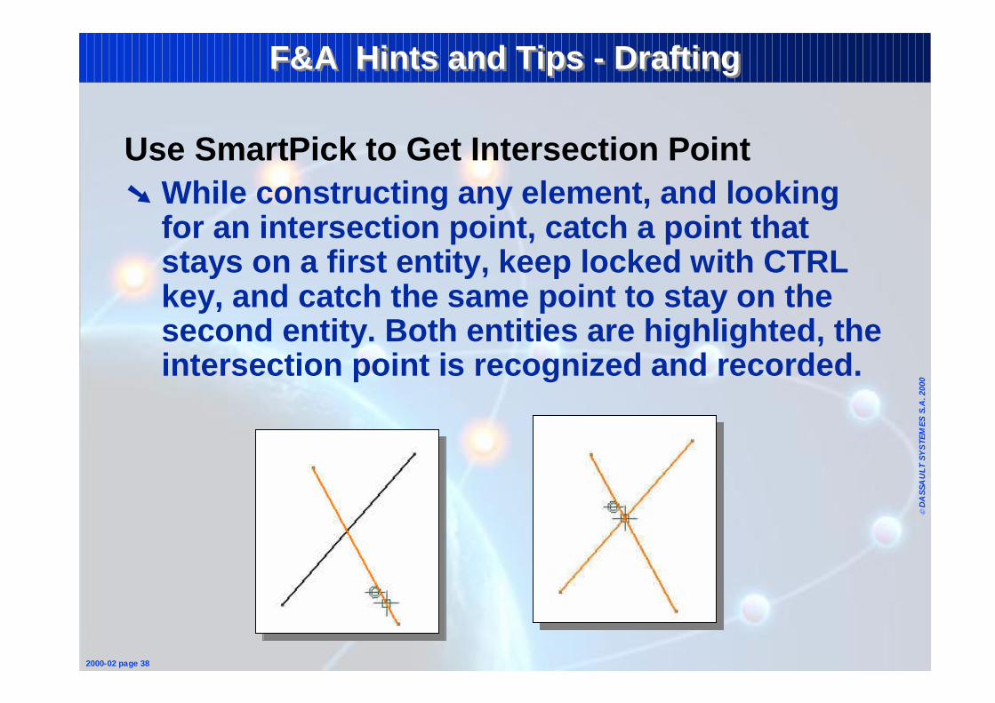
Use SmartPick to Get Intersection Point➘ While constructing any element, and looking
for an intersection point, catch a point that stays on a first entity, keep locked with CTRL key, and catch the same point to stay on the second entity. Both entities are highlighted, the intersection point is recognized and recorded.
Page 33
© D
ASS
AU
LT S
YS
TEM
ES S
.A. 2
000
2000-02 page 39
F&A Hints and Tips - DraftingF&A Hints and Tips - Drafting
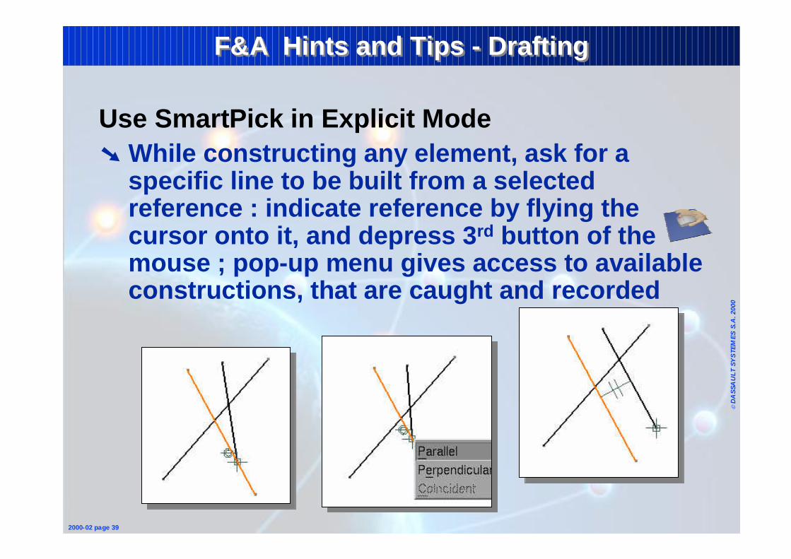
Use SmartPick in Explicit Mode➘ While constructing any element, ask for a
specific line to be built from a selected reference : indicate reference by flying the cursor onto it, and depress 3rd button of the mouse ; pop-up menu gives access to available constructions, that are caught and recorded
Page 34
© D
ASS
AU
LT S
YS
TEM
ES S
.A. 2
000
2000-02 page 40
F&A Hints and Tips - DraftingF&A Hints and Tips - Drafting
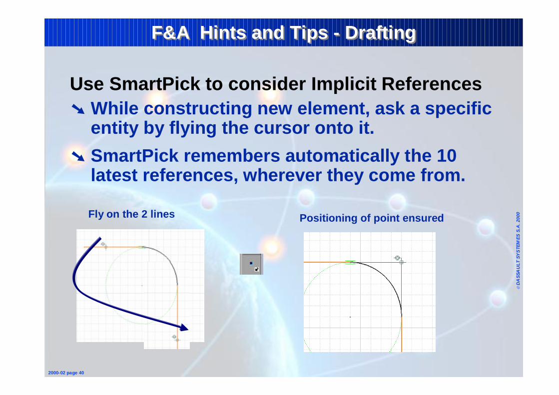
Use SmartPick to consider Implicit References➘ While constructing new element, ask a specific
entity by flying the cursor onto it.
➘ SmartPick remembers automatically the 10 latest references, wherever they come from.
Positioning of point ensuredFly on the 2 lines
Page 35
© D
ASS
AU
LT S
YS
TEM
ES S
.A. 2
000
2000-02 page 41
F&A Hints and Tips - DraftingF&A Hints and Tips - Drafting
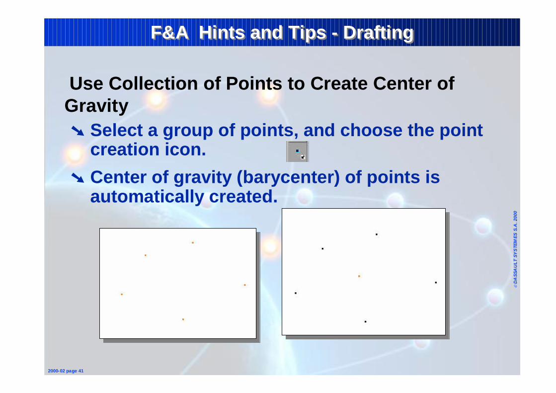
Use Collection of Points to Create Center of Gravity➘ Select a group of points, and choose the point
creation icon.
➘ Center of gravity (barycenter) of points is automatically created.
Page 36
© D
ASS
AU
LT S
YS
TEM
ES S
.A. 2
000
2000-02 page 42
F&A Hints and Tips - DraftingF&A Hints and Tips - Drafting
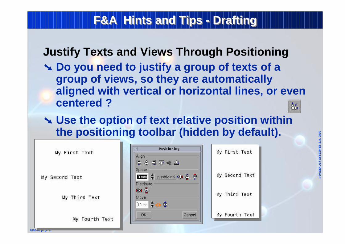
Justify Texts and Views Through Positioning➘ Do you need to justify a group of texts of a
group of views, so they are automatically aligned with vertical or horizontal lines, or even centered ?
➘ Use the option of text relative position within the positioning toolbar (hidden by default).
Page 37
© D
ASS
AU
LT S
YS
TEM
ES S
.A. 2
000
2000-02 page 43
F&A Hints and Tips - DraftingF&A Hints and Tips - Drafting
Use Line-Up on Collection of Dimensions➘ Do you need to align a group of dimensions, so
they form vertical or horizontal systems ?
➘ Use the option of line-up within the positioning toolbar (hidden by default).
➘ First select the dimensions to align, choose line-up option, and indicate the reference dimension or line. Click anywhere in the drawing to specify exact alignment (offset is then equal to 0).
Page 38
© D
ASS
AU
LT S
YS
TEM
ES S
.A. 2
000
2000-02 page 44
F&A Hints and Tips - DraftingF&A Hints and Tips - Drafting
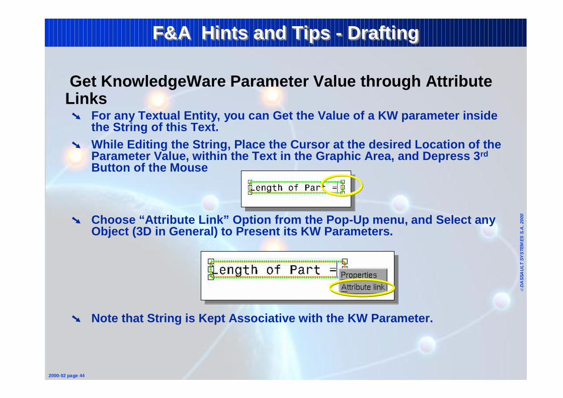
Get KnowledgeWare Parameter Value through Attribute Links➘ For any Textual Entity, you can Get the Value of a KW parameter inside
the String of this Text.➘ While Editing the String, Place the Cursor at the desired Location of the
Parameter Value, within the Text in the Graphic Area, and Depress 3rd
Button of the Mouse
➘ Choose “Attribute Link” Option from the Pop-Up menu, and Select any Object (3D in General) to Present its KW Parameters.
➘ Note that String is Kept Associative with the KW Parameter.
Page 39
© D
ASS
AU
LT S
YS
TEM
ES S
.A. 2
000
2000-02 page 46
F&A Hints and Tips - DraftingF&A Hints and Tips - Drafting
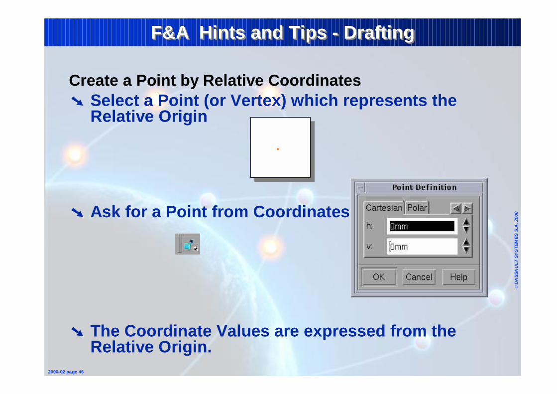
Create a Point by Relative Coordinates➘ Select a Point (or Vertex) which represents the
Relative Origin
➘ Ask for a Point from Coordinates
➘ The Coordinate Values are expressed from the Relative Origin.
Page 40
© D
ASS
AU
LT S
YS
TEM
ES S
.A. 2
000
2000-02 page 48
F&A Hints and TipsF&A Hints and Tips
1 - Fundamentals• Sketcher• Wireframe & Surfaces• Part• Assembly• Drafting
2 - Reminders• Common Tools
Page 41
© D
ASS
AU
LT S
YS
TEM
ES S
.A. 2
000
2000-02 page 49
F&A Hints and Tips - ToolbarsF&A Hints and Tips - Toolbars
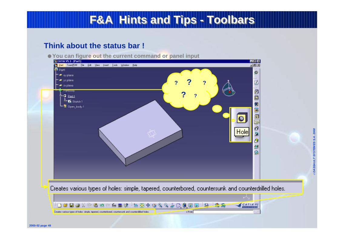
Think about the status bar !● You can figure out the current command or panel input
? ? ?
? ?
Page 42
© D
ASS
AU
LT S
YS
TEM
ES S
.A. 2
000
2000-02 page 50
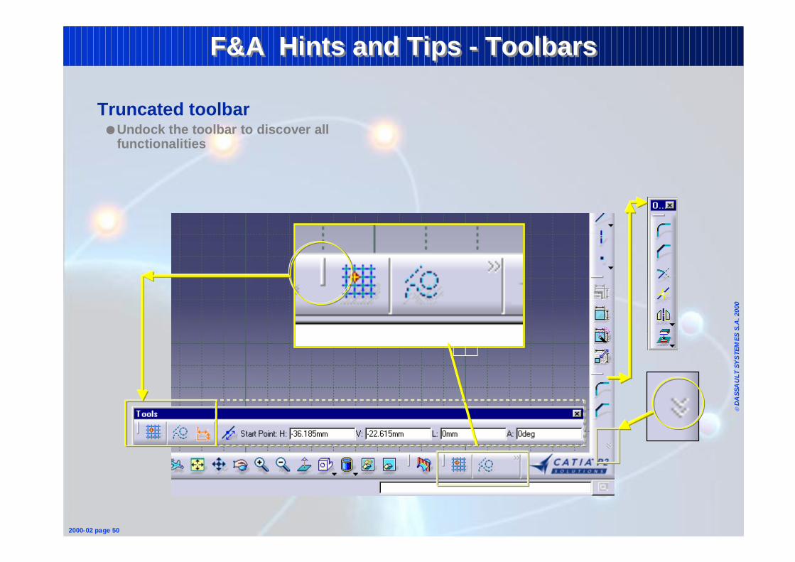
F&A Hints and Tips - ToolbarsF&A Hints and Tips - Toolbars
Truncated toolbar● Undock the toolbar to discover all
functionalities
Page 43
© D
ASS
AU
LT S
YS
TEM
ES S
.A. 2
000
2000-02 page 51
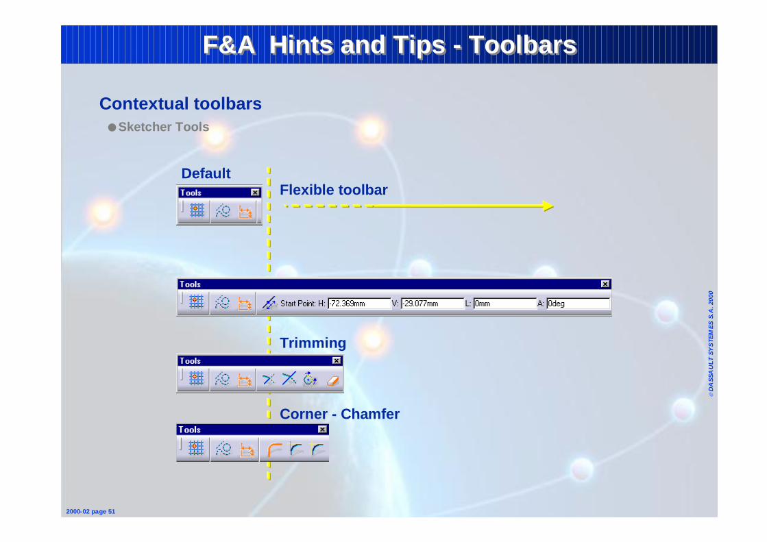
Contextual toolbars● Sketcher Tools
Default
Drawing commands (i.e.: line, circle, sketch, …)
Trimming
Flexible toolbar
Corner - Chamfer
F&A Hints and Tips - ToolbarsF&A Hints and Tips - Toolbars
Page 44
© D
ASS
AU
LT S
YS
TEM
ES S
.A. 2
000
2000-02 page 52
F&A Hints and Tips - ToolbarsF&A Hints and Tips - Toolbars
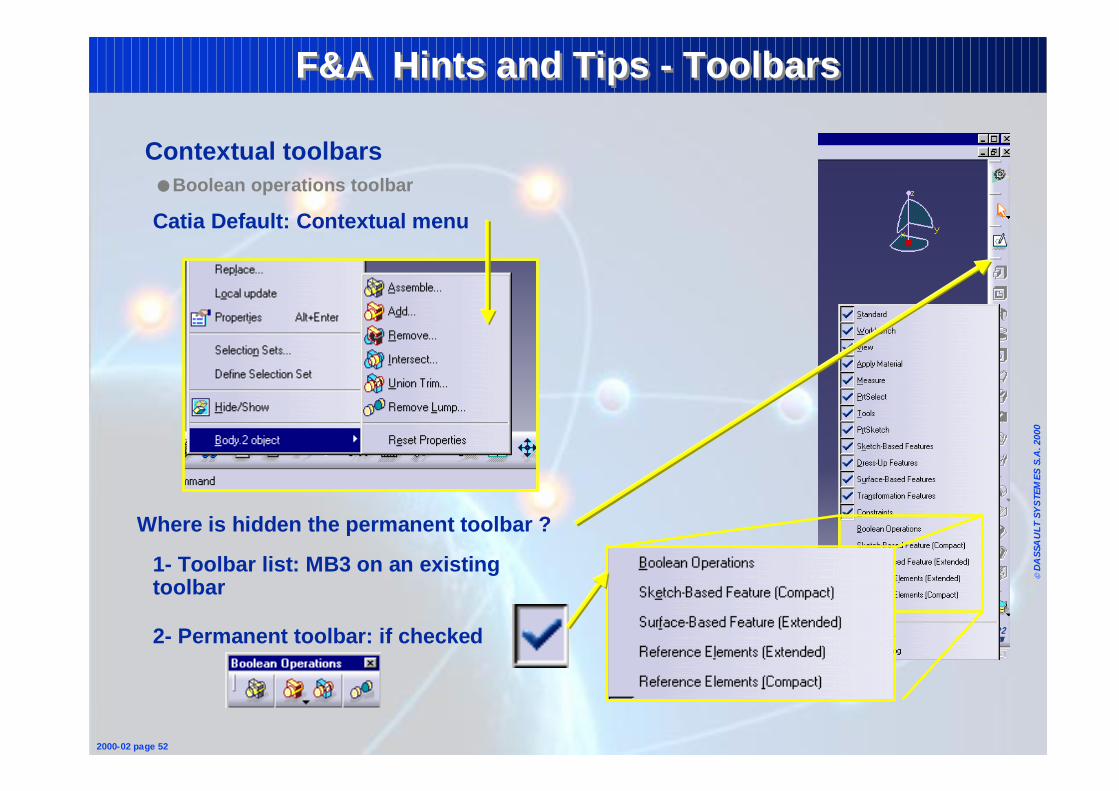
2- Permanent toolbar: if checked
Contextual toolbars● Boolean operations toolbar
Catia Default: Contextual menu
1- Toolbar list: MB3 on an existing toolbar
Where is hidden the permanent toolbar ?
Page 45
© D
ASS
AU
LT S
YS
TEM
ES S
.A. 2
000
2000-02 page 53
F&A Hints and Tips - ToolbarsF&A Hints and Tips - Toolbars
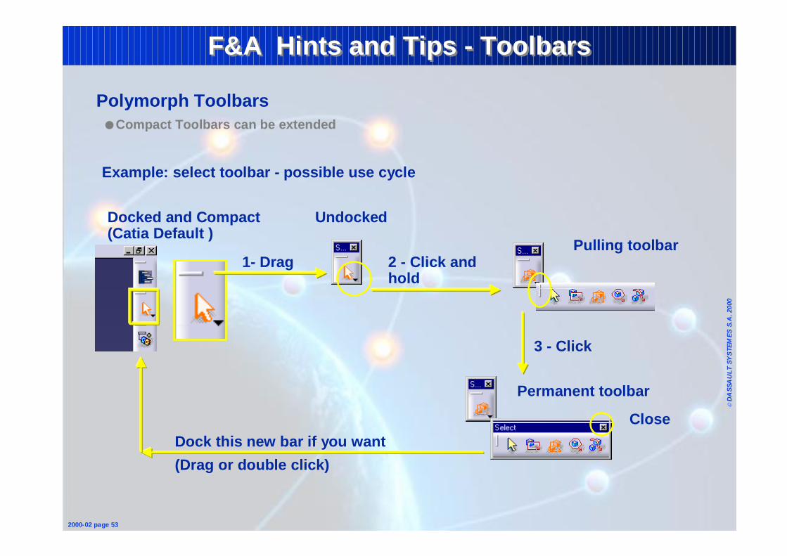
Example: select toolbar - possible use cycle
Docked and Compact (Catia Default )
Undocked
Pulling toolbar
Permanent toolbar
2 - Click and hold
1- Drag
3 - Click
Dock this new bar if you want
(Drag or double click)
Polymorph Toolbars● Compact Toolbars can be extended
Close
Page 46
© D
ASS
AU
LT S
YS
TEM
ES S
.A. 2
000
2000-02 page 54
F&A Hints and Tips - ToolbarsF&A Hints and Tips - Toolbars
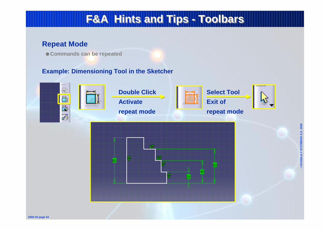
Repeat Mode● Commands can be repeated
Example: Dimensioning Tool in the Sketcher
Double Click
Activate
repeat mode
Select Tool
Exit of
repeat mode
Page 47
© D
ASS
AU
LT S
YS
TEM
ES S
.A. 2
000
2000-02 page 55
F&A Hints and Tips - ToolbarsF&A Hints and Tips - Toolbars
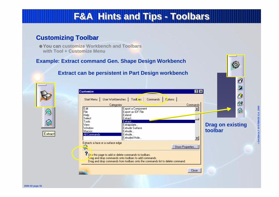
Customizing Toolbar● You can
Example: Extract command Gen. Shape Design Workbench
Extract can be persistent in Part Design workbench
Drag on existing toolbar
Customizing Toolbar● You can
Customizing Toolbar● You can customize Workbench and Toolbars
with Tool + Customize Menu
Page 48
© D
ASS
AU
LT S
YS
TEM
ES S
.A. 2
000
2000-02 page 56
F&A Hints and Tips - WorkbenchF&A Hints and Tips - Workbench
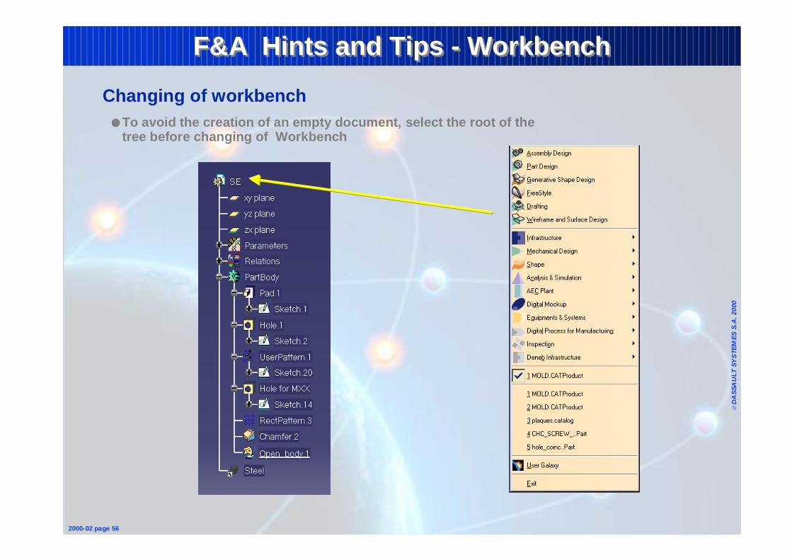
Changing of workbench● To avoid the creation of an empty document, select the root of the
tree before changing of Workbench
Page 49
© D
ASS
AU
LT S
YS
TEM
ES S
.A. 2
000
2000-02 page 57
F&A Hints and Tips - Specification Tree F&A Hints and Tips - Specification Tree
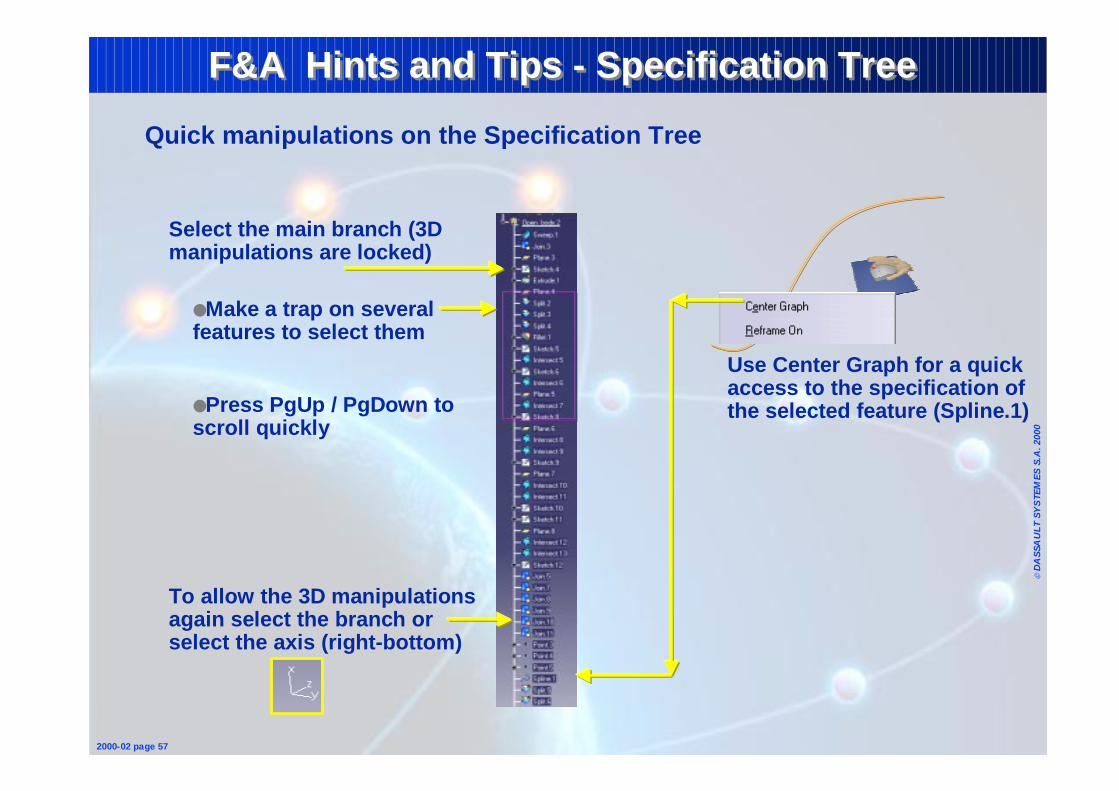
Quick manipulations on the Specification Tree
Select the main branch (3D manipulations are locked)
●Make a trap on several features to select them
●Press PgUp / PgDown to scroll quickly
To allow the 3D manipulations again select the branch or select the axis (right-bottom)
Use Center Graph for a quick access to the specification of the selected feature (Spline.1)
Page 50
© D
ASS
AU
LT S
YS
TEM
ES S
.A. 2
000
2000-02 page 58
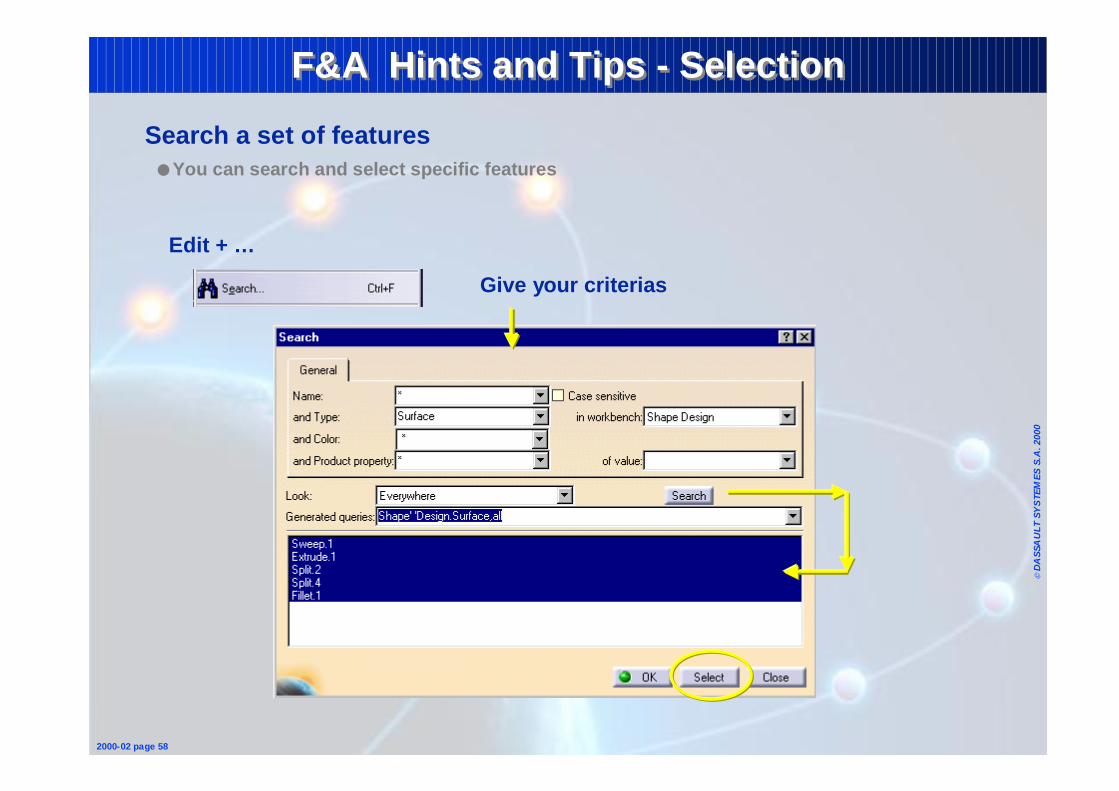
F&A Hints and Tips - SelectionF&A Hints and Tips - Selection
Search a set of features● You can search and select specific features
Edit + …
Give your criterias