USED WITH OR WITHOUT lNSTALLATION KIT,ELECTRONIC EQUIPMENT MODIFICATION KIT MK-2488/G
TM 11-5815-334-10, 5 March 1985, is changed as follows:
1. Remove old pages and Insert new pages as indicated below. New or changed material is indicated bya vertical bar in the margin of the page.
Remove pages Insert pagesi through 1-2 i through 1-21-5 and 1-6 1-5 and 1-61-23 through 1-26 1-23 through 1-262-5 and 2-6 2-5 and 2-62-11 through 2-14 2-11 through 2-142-23 through 2-26 2-23 through 2-262-65 and 2-66 2-65 and 2-662-68.1 and 2-68.2 2-68.1 and 2-68.22-68.5 and 2-68.6 2-68.5 and 2-68.62-71 and 2-72 2-71 and 2-722-83 and 2-84 2-83 and 2-842-107 through 2-110 2-107 through 2-1102-131 and 2-132 2-131 and 2-132B-3 through B-30 B-3 (blank) through B-36 (blank)C-1 and C-2 C-1 and C-2
2. File this change sheet in the front of the publication for reference purposes.
Distribution authorized to the Department of Defense and DODcontractors only for official use or for administration or operationalpurposed. This determination was made on 15 August 1993. Otherrequests for this document will be referred to (Commander, US ArmyCommunication—Electronics Command and Fort Monmouth, ATTN:AMSEL-LC-LM-LT, Fort MonmouthNJ 07703-5007.
DESTRUCTION NOTICE - Destroy by any method that will preventdisclosure of contents or reconstruction of the document.
TM 11-5815-334-10, 5 March 1985, is changed as follows:
1. Remove old pages and insert new pages as indicated below. New orchanged material is indicated by a vertical bar in the margin of thepage.
Remove pages Insert pages
i and ii i and ii2-25 through 2-28 2-25 through 2-28None 2-28.1 through 2-28.8
2. File this change sheet in the front of the publication forreference purposes.
Distribution authorized to the Department of Defense or DOD contractors onlyfor official use or for administration or operational purposess. This determinationwas made on 15 May 1989. Other requests for this document will be referredto Commander, US Army Communications-Electronics Command and FortMonmouth, ATTN: AMSEL-LC-ME-P, Fort Monmouth, NJ 07703-5000.
DESTRUCATI0N NOTICE – Destroy by any method that will prevent disclosure ofcontents or reconstruction of the document.
By Order of the Secretary of the Army:
Official:
WILLIAM J. MEEHAN IIBrigadier General, United States Army
The Adjutant General
CARL E. VUONOGeneral, United States Army
Chief of Staff
DISTRIBUTION:To be distr ibuted in accordance with DA Form 12-31 operator require-
USED WITH OR WITHOUT INSTALLATION KIT,ELECTRONIC EQUIPMENT MODIFICATION KIT MK-2488/G
TM 11-5815-334-10, 5 March 1985, is
1. Title of the manual is changed as
changed as follows:
shown above.
2. Remove old pages and insert new pages as indicated below. New or changed material is indicated by a vertical barin the margin of the page. Added or revised illustrations are indicated by a vertical bar adjacent to the identificationnumber,
Distribution authorized to the Department of Defense and DOD contractors onlyfor official use or for administration or operational purposes. This determinationwas made on 26 August 1988. Other requests for this document will be referredto Commander, US Army Communications-Electronics Command and FortMonmouth, ATTN: AMSEL-LC-ME-P, Fort Monmouth, NJ 07703-5000.
DESTRUCTION NOTICE – Destroy by any method that will prevent disclosure ofcontents or reconstruction of the document.
TM 11-5815-334-10, 5 March 1985, is changed as follows:1. Remove old pages and insert new pages as indicated below. New or changed material is indicated by
a vertical bar in the margin of the page. Added or revised illustrations are indicated by a vertical bar adjacent to
the identif ication number.
Remove pages
E and F1-1 and 1-21-5 and 1-61-15 through 1-182-9 and 2-102-15 and 2-162-21 and 2-222-27 and 2-282-63 through 2-662-69 and 2-702-147 and 2-148A-1 and A-2B-5 through B-8B-11 and B-12B-17 and B-18B-23 and B-24B-29 and B-30
Insert pages
E and F1-1 and 1-21-5 and 1-61-15 through 1-182-9 and 2-102-15 and 2-162-21 and 2-222-27 and 2-282-63 through 2-662-69 and 2-702-147 and 2-148A-1 and A-2B-5 through B-8B-11 and B-12B-17 and B-18B-23 and B-24B-29 and B-30
2. File this change sheet in the front of the publication for reference purposes.
Distribution authorized to the Department of Defense and DOD contractors onlyfor official use or for administration or operational purposes. This determinationwas made on 23 June 1987. Other requests for this document will be referredto Commander, US Army Communications-Electronics Command and FortMonmouth, ATTN: AMSEL-ME-P, Fort Monmouth, NJ 07703 -5000.
DESTRUCTION NOTICE–Destroy by any method that willprevent disclosure of contents or reconstruction of thedocument.
By Order of the Secretary of the Army:
Official:
CARL E. VUONOGeneral, United States Army
Chief of Staff
R.L. DILWORTHBrigadier General, United States Army
The Adjutant General
DISTRIBUTION:To be distributed in accordance with DA Form 12-51 literature
requirements for AN/GRC-122; AN/GRC-142.
TM 11-5815-334-10
+SAFETY STEPS TO FOLLOW IF SOMEONE IS THEVICTIM OF ELECTRICAL SHOCK
DO NOT TRY TO PULL OR GRAB THE INDIVIDUAL
IF POSSIBLE, TURN OFF THE ELECTRICAL POWER
IF YOU CANNOT TURN OFF THE ELECTRICALPOWER, PULL, PUSH, OR LIFT THE PERSON TOSAFETY USING A WOODEN POLE OR A ROPE ORSOME OTHER INSULATING MATERIAL
SEND FOR HELP AS SOON AS POSSIBLE
AFTER THE INJURED PERSON IS FREE OFCONTACT WITH THE SOURCE OF ELECTRICALSHOCK, MOVE THE PERSON A SHORT DISTANCEAWAY AND IMMEDIATELY START ARTIFICIALRESUSCITATION
A
TM 11-5815-334-10
WARNING
WARNING
HIGH VOLTAGE
IS USED IN THE OPERATION OF THIS EQUIPMENT
DEATH ON CONTACT
MAY RESULT IF PERSONNEL FAIL TO OBSERVE SAFETY PRECAUTIONS
Never work on electronic equipment unless there is another person nearbywho is familiar with the operation and hazards of the equipment and who iscompetent in administer ing f i rst a id. When the technician is aided byoperators, he must warn them about dangerous areas.
Whenever possible, the power supply to the equipment must be shut offbefore beginning work on the equipment. Take particular care to ground everycapacitor likely to hold a dangerous potential. When working inside the equip-ment, after the power has been turned off, always ground every part beforetouching it.
Be careful not to contact high-voltage connections of 115 volt ac input con-nections when installing or operating this equipment.
When installing or operating this equipment, be careful not to touch high-voltage connections of 115 vac.
Whenever the nature of the operat ion permits, keep one hand awayfrom the equipment to reduce the hazard of current flowing through vitalorgans of the body.
Remove all jewelry before working on electronic equipment.
WARNING Do not be misled by the term “low voltage”. Potentials as low as50 volts may cause death under adverse conditions.
For Artificial Respiration, refer to FM 21-11.
B
TM 11-5815-334-10
WARNINGRADIATION HAZARD
RADIOACTIVE MATERIALCONTROLLED DISPOSAL REQUIREDACCOUNTABILITY NOT REQUIRED
STD RW–2
Meter Ra226 1.0uCi 6625-00-257-1103Meter Ra 226 0.6uCi 6625-00-226-5680Meter arbitrary Ra 226 1.0uCi 6625-00-226-5679
scaleMeter, arbitrary Ra 226 1.0uCi 6625-00-226-5681
scale
Radiation Hazard Information: The following radiation hazard in-
formation must be read and understand by all Personnel operating orrepairing Radio Teletypetwriter Sets AN/GRC-122/142(*).
Hazardous radioactive materials are present in the above listed com-ponents of the MD-522/GRC. RT-662/GRC, RT-824/GRC, and the AM-3349/GRC. The components are potentially hazardous when broken. Seequalified medical personnel and the local Radiological Protection Officer(RPO) immediately if you are exposed to or cut by broken components.First aid instructions are contained in TB 43-0116, and TB 43-0122.
NEVER place radioactive components in your pocket.Use extreme care NOT to break radioactive components while handlingthem.NEVER remove radioactive components from cartons until you are readyto use them.If any of these components are broken, notify the local RPO immediately.The RPO will survey the immediate area for radiological contaminationand will supervise the removal of broken components.The above listed radioactive components will not be repaired or
disassembled.Disposal of broken, unserviceable, or unwanted radioactive components
will be accomplished in accordance with the instructions in AR 755-15.
C
TM 11-5815-334-10
WARNINGSERIOUS INJURY OR EVEN DEATH CAN HAPPEN IF THE FOLLOWING ARE NOT CAREFULLY
OBSERVED WHEN INSTALLING AND USING THE ANTENNAS USED WITH YOUR RADIO SETS
1. ARE THERE ANY POWERLINES IN YOUR AREA OF OPERATION ?
2. HOW HIGH ARE THESE POWERLINES ?
3. HOW TALL ARE THE POLES OR TOWERS CARRYING POWERLINES ?
MOBILE OPERATION WITH WHIP ANTENNAS
DO NOT STOP YOUR VEHICLE UNDER POWERLINES.
● IF POSSIBLE, TRY TO MAINTAIN MOBILE COMMUNICATIONS WITHYOUR ANTENNA(S) TIED DOWN .
● MAKE SURE AN ANTENNA TIP CAP IS SECURELY TAPED ON THEEND OF EACH WHIP ANTENNA.
● DO NOT LEAN AGAINST OR TOUCH A WHIP ANTENNA WHILE THETRANSMITTER IS ON.
● DURING CROSS-COUNTRY OPERATION, DO NOT ALLOW ANYONETO STICK AN ARM, LEG OR WEAPON OVER THE SIDES OF THEVEHICLE. IF YOUR ANTENNA ACCIDENTALLY TOUCHES APOWERLINE AND A LEG, ARM OR WEAPON CONTACTS A DAMPBUSH OR THE GROUND, A SERIOUS OR FATAL ACCIDENT CANHAPPEN .
● IF YOU ARE NOT SURE THAT AN ANTENNA ON YOUR VEHICLEWILL CLEAR A POWERLINE, STOP BEFORE YOU GET CLOSETO THE POWERLINE AND EITHER CAREFULLY TIE DOWN THEANTENNA OR REMOVE ANTENNA SECTIONS TO MAKE SURETHAT YOU CAN SAFELY DRIVE UNDER THE POWERLINE.
D
TM 11-5815-334-10
FIXED OPERATION WITH LONG RANGE ANTENNAS
WARNING
TELECOPING ANTENNA
MAST
TYPICAL TOWER EXTENDED RANGE
ANTENNA
DOUBLET ANTENNA
NEVER ERECT THESE L0NG RANGE ANTENNAS DIRECTLY UNDER POWERLINES.IF YOU MUST ERECT THESE LONG RANGE ANTENNAS NEAR POWERLINES, POWERLINE POLES ORTOWERS, OR BUILDINGS WITH OVERHEAD POWERLINE CONNECTIONS, NEVER PUT THE ANTENNACLOSER THAN TWO TIMES THE ANTENNA HEIGHT FROM THE BASE OF THE POWERLINE, POLE,
TOWER OR BUILDINGS.
NEVER ATTEMPT TO ERECT ANY LONG RANGE ANTENNA WITHOUT A FULL TEAM.BEFORE ERECTING ANY LONG RANGE ANTENNA, INSPECT ALL THE PARTS MAKING UP THEANTENNA KIT. DO NOT ERECT THE ANTENNA IF ANY PARTS ARE MISSING OR DAMAGED.
DO AS MUCH OF THE ASSEMBLY WORK AS POSSIBLE ON THE GROUND.
WHEN ERECTING THE ANTENNA, ALLOW ONLY TEAM PERSONNEL IN THE ERECTION AREA.
MAKE SURE THAT THE AREA FOR THE ANCHORS IS FIRM. IF THE GROUND IS MARSHY OR SANDY,
GET SPECIFIC INSTRUCTIONS FROM YOUR CREW CHIEF OR SUPERVISOR ON HOW TO REINFORCETHE ANCHORS,.
WHEN SELECTING LOCATIONS FOR ANCHORS, AVOID TRAVELED AREAS AND ROADS. IF YOU CANNOTAVOID THESE AREAS, GET SPECIFIC INSTRUCTIONS FROM YOUR SUPERVISOR AS TO WHAT CLEAR-ANCE YOUR GUY WIRES AND ROPES MUST HAVE OVER THE TRAVELED AREAS AND ROAD.
CLEARLY MARK ALL GUY WIRES AND ROPES WITH THE WARNING FLAGS OR SIGNS SUPPLIED BY YOURU N I T . IN AN EMERGENCY, USE STRIPS OF WHITE CLOTH AS WARNING STREAMERS,
IF YOU SUSPECT THAT POWERLINES HAVE MADE ACCIDENTAL CONTACT WITH YOUR ANTENNA, STOPOPERATING, ROPE OFF THE ANTENNA AREA, AND NOTIFY YOUR SUPERIORS.
IF THE WEATHER IN YOUR AREA CAN CAUSE ICE TO FORM ON YOUR LONG RANGE ANTENNA AND ITS
GUY WIRES AND ROPES, ADD EXTRA GUYS TO SUPPORT THE SYSTEM. ROPE OFF THE AREA ANDPOST IT WITH WARNING SIGNS LIKE “BEWARE OF FALLING ICE".
DO NOT TRY TO ERECT ANY ANTENNA DURING AN ELECTRlCAL STORM.
KEEP A SHARP EYE ON YOUR ANCHORS AND GUYS. CHECK THEM DAILY AND IMMEDIATELYBEFORE AND AFTER BAD WEATHER.
Change 2 E
TM 11-5815-334-10
WARNING
TRICHLOROTRIFLUOROETHANE
Fumes of TRICHLOROTRIFLUOROETHANE are poisonous. Provide adequate ventilationwhenever you use TRICHLOROTRIFLUOROETHANE. Do not use solvent near heat or openflame. TRICHLOROTRIFLUOROETHANE will not burn, but heat changes the gas intopoisonous, irritating fumes. DO NOT breathe the fumes or vapors. TRICHLOROTRl-FLUOROETHANE dissolves natural skin oils. DO NOT get the solvent on your skin, usegloves, sleeves and an apron which the solvent cannot penetrate. If the solvent is takeninternally, consult a physician immediately.
W A R N I N G
COMPRESSED AIR
Compressed air is dangerous and can cause serious bodily harm if protective means ormethods are not observed to prevent a chip or particle (of whatever size) from beingblown into the eyes or unbroken skin of the operator or other personnel. Compressed airshall not be used for cleaning purposes except where reduced to less than 29 psi,(199.95 Kilopascals) and then only with effective chip guarding and personnel protec-tive equipment. Do not use compressed air to dry parts when TRICHLOROTRIFLUORO-ETHANE has been used.
CAUTION
Throughout the manual, the primary power rating is given as 115 v ac ±10%. AS theequipment power switches are turned on, the primary voltage may drop to some valuein the ±10% range, but it should not remain at the changed level, but return to theoriginal 115 v ac. If the level does drop and stay at a constant level, have the repairperson check the condition of the last circuit turned on which created this condition.
F Change 2
Technical Manual HEADQUARTERSDEPARTMENT OF THE ARMY
USED WITH OR WITHOUT INSTALLATION KIT, ELECTRONIC EQUIPMENT KIT MK-2488/G
REPORTING ERRORS AND RECOMMENDING IMPROVEMENTS
You can help improve this manual. If you find any mistakes or if you know of away to improve the procedures, please let us know. Mail your letter, DA Form2028 (Recommended Changes to Publications and Blank Forms), or DA Form2028-2 located in back of this manual direct to:Commander, US Army Communications-Electronics Command and FortMonmouth, ATTN: AMSEL-LC-LM-LT, Fort Monmouth, NJ 07703-5007. A replywill be furnished direct to you.
This manual is designed to help you operate and maintain the AN/GRC-122/142(*).The front cover table of contents is provided for quick reference to important infor-mation. There is also an index located in the final pages for use in locating specificof information.
items
Measurements in this manual are sometimes given in both US standard and metric units.A metric to US standard conversion chart can be found on the inside back cover.
Read all preliminary information found at the beginning of each task. It has importantinformation and safety instructions you must follow before beginning the task.
Warning pages are located in the front of this manual. You should learn the warningsbefore operating or doing maintenance on the equipment.
Paragraphs in this manual are numbered by chapter and order of appearance within achapter. A subject index appears at the beginning of each chapter, listing sections thatare included in that chapter. A more specific subject index is located at the beginning ofeach section to help you find the exact paragraph you’re looking for.
This manual covers 24 different models. Applicable model numbers will be listed inparagraph titles. If paragraphs are applicable to all models of the equipment, anasterisk (*) will follow the model number.
Instructions for performing operator PMCS are located in paragraph 2-4.
Instructions for using operator troubleshooting tables are located in paragraph 3-1.
Equipment Name and Model Number: The 12 shelters described in this manual are radio teletypewritersets. There are two basic configurations; AN/GRC-122, which can be configured as AN/GRC-122A,AN/GRC-122B, AN/GRC-122C, AN/GRC-122D or AN/GRG122E, and AN/GRC-142, which can beconfigured as AN/GRC-142A/AN/GRGC-142B, AN/GRC-142C, AN/GRC-142D or AN/GRC-142E. Theasterisk (*) following AN/GRC-122(*) or AN/GRC-142(*) Indicates all models of that configuration. Anasterisk (*) following AN/GRC-122/142(*) indicates all 12 models.
Purpose of Equipment Provides a front-line secure or nonsecure radio or teletypewriter one-wayreversible, AN/GRC-142(*), or simultaneous transmission and reception, AN/GRC-122(*),communications system. The communications system is housed in a mobile, all weather front-lineshelter.
1-2. MAINTENANCE FORMS, RECORDS, AND REPORTS.
a. Reports of Maintenance and Unsatisfactory Equipment Department of the Army forms andprocedures used for equipment maintenance will be those prescribed by DA Pam 738-750, as containedin Maintenance Management Update.
b. Reporting of item and Packaging Discrepancies. Fill out and forward SF 364 (Report ofDiscrepancy (ROD)) as prescribed in AR 735-11-2/DLAR 4140.55 SECNAVINST 4355.18/AFR400-54/MCO 4430.3H.
c. Transportation Discrepancy Report (TDR) (SF 361). Fill out and forward TransportationDiscrepancy Report (TDR) (SF 361) as prescribed in AR 55-38/NAVSUPINST 4610.33C/AFR 75-18/MCOP4610.19D/DLAR 4500.15.
Change 4 1-1
TM 11-5815-334-10
1-3. HAND RECEIPT (-HR) MANUALS.
This manual has a companion document with a TM number followed by -HR (which stands for HandReceipt). The TM 11-5815-334-10-HR for AN/GRC-122/142(*) consists of preprinted hand receipts (DAForm 2062) that list end item related equipment (i.e., components of end item list, basic issue items list,and additional authorization list) you must account for. As an aid to property accountability, additional-HR manuals maybe requisitioned from the US Army Adjutant General Publications Center in Baltimore,Maryland, in accordance with the procedures in Chapter 3, AR 310-2 and DA Pam 310-10.
1-4. CONSOLIDATED INDEX OF ARMY PUBLICATIONS AND BLANK FORMS.
Refer to the latest issue of DA Pam 25-30 to determine whether there are new editions, changes, oradditional publications pertaining to the equipment.
If your equipment needs improvement, let us know. Send us an EIR. You, the user, arethe only one who can tell us what you don’t like about your equipment. Let us know whyyou don’t like the design or performance. Put it on an SF 368 (Product Quality DeficiencyReport). Mail it to: Commander, US Army Communications-Electronics Command andFort Monmouth, ATTN: AMSEL-LC-ED-CFO, Fort Monmouth, New Jersey 07703-5023.We’ll send you a reply.
1-6. DESTRUCTION OF ARMY ELECTRONICS MATERIEL
Destruction of Army electronics materiel to prevent enemy use shall be in accordance with TM 750-244-2.Comsec equipment and keying information has first priority. in addition, refer to KOA-133( ) TSEC foradditional information on the TSEC/KG-27.
1-6.1. ADMINISTRATIVE STORAGE.
Administrative storage of equipment issued to and used by Army activities will have PreventiveMaintenance Checks and Services (PMCS) performed before storing. When removing the equipmentfrom administrative storage, the PMCS checks should be performed to assure operational readiness.
1-7. NOMENCLATURE CROSS-REFERENCE LIST.
This list contains common names used throughout this manual in place of official nomenclature.
COMMON NAME I OFFICIAL NOMENCLATURE
amplifierAN/UGC-74 A(V)3 orAN/UGC-74 B(V)3
control groupcontrol paneldoublet antennadummy boxhandsetheadse t
Teletypewriter, TT-98/FG or TT-722(*)/TGVoltmeter, ME-345/GRCWhip Antenna Consisting of:
Mast Base AB-652/GRMast Section MS-116AMast Section MS-117AMast Section MS-118A
WORD OR TERM
automatic gain controlamplitude modulationbeat frequency oscillatorcontinuous waveduplexfrequency shift keyedmilliampsnormal input keyingnarrow frequency shift keyedorder wireone way reversiblesingle sidebandteletypewritervoltage standing wave ratiowords per minute
1-3
TM 11-5815-334-10
1-9. GLOSSARY.
This list contains definitions of unusual words or terms used in this manual.
WORD OR TERM
A S C I I
Baudot Code
Baud Rate
Compatible AM.
Continuous Wave (CW)
Diversity
Duplex (dx)
Frequency Shift Keying (fsk)850 Hz, Narrow Frequency ShiftKeying (nsk) 85 Hz
Halyard
One-Way Reversible (owr)
Order Wire (OW)
Single Sideband (ssb)
DEFINITION
A code that uses eight bits to make up onecharacter.
A transmission code used in tty operation. Onecharacter is made up of five bits.
A unit of measurement used to determine thespeed of data transfer.
An am. signal that is compatible with ssb.
Electric current of constant amplitude andfrequency.
The capability of sending the same signalsimultaneously over several different trans-mission paths.
Transmission and reception at the same time.
A form of frequency modulation in which the modu-lating wave shifts the output frequency betweentwo predetermined values (mark and space).
A rope for hoisting and lowering.
Transmission in one direction, and back in theopposite direction but not at the same time.
Transmission path between two stations that isindependent of channels in use.
Transmission of either upper or lower sidebandto cut power and bandwidth to one-half that ofa normal transmission.
1-10. SECURITY CLASSIFICATION MARKINGS.
The following codes tell you the classification of the title and contents of a manual:
a. When a (U) appears before the title of the document, it means that the title of the document isunclassified.
b. When a (C) appears before the document number, it means the contents of the document areclassified confidential.
1-11. EQUIPMENT CHARACTERISTICS, CAPABILITIES AND FEATURES.
CHARACTERISTICS
Can be operated over land lines from a remote site up to 1 mile away from shelter.The AN/GRC-122(*) is capable of simultaneously transmit and receive (Duplex operation).Remote duplex operation.Teletypewriter one-way reversible transmit/eceive over land lines when not operating in duplex mode.Can operate on 110 vac 60 Hz, or 28 vdc.
CAPABILITIES AND FEATURES
Transportable by air or truck.Can be used in secure or nonsecure operations.Accommodates security equipment.Can be used with up to six teletypewriters.Communication between shelter and remote site over land lines.AN/GRC-122/142C, D, and E models (with or without MK-2488/G) are modified to incorporateCommunications Terminal AN/UGC-74A(V)3.AN/UGC-74A(V)3 can compose, edit, transmit, receive, store, and print messages.Terminal is usable at signaling speeds of 45.5, 50,7 5, 150, 300, 600, and 1200 baud (bits per
second) using the internal clock. (45.5, 50 and 75 with MK-2488/G.)AN/GRC-122/142(*) operates at a frequency range of 2.0 to 29.999 MHz and is capable of the
following modes of operation:
I
85 Hertz, 85-Hertz diversity, or 850-Hertz fsk local owr operation,Compatible am or ssb voice owr local or remote operation.Simultaneous local 85-Hertz nsk and voice owr reception.Cw local or remote operation.
Change 2 1-5
TM 11-5815-334-10
1-11. EQUIPMENT CHARACTERISTICS, CAPABILITIES AND FEATURES. (CONT)
AN/GRC-122(*) contains the following additional equipment for duplex operations:
RT-662/GRCAntennaAuxiliaty loudspeakerInvertor or motor generatorAdditional TT-98/FG or Communications Terminal AN/UGC-74A(V)3.
AN/GRC-142(*) does not have the additional units listed above but is wired to accommodate thisequipment. With the addition of teletypewriter TT-98/FG or AN/UGC-74A(V)3 at a remote site, thefollowing modes of operation are possible:
Radio Teletypewriter Sets AN/GRC-122/142(*)(with MK-2488/G) can be used with each other and withRadio Teletypewriter Sets AN/VSC-2 and AN/VSC-3 (with MK-2488/G).
1-12. LOCATION AND DESCRIPTION OF MAJOR COMPONENTS.
The two different shelters used (S-250 and S-318(*)/G) provide three basic configurations of equipment bythe rack arrangement. The location and description of major components are described in three sections:AN/GRC-122/142 Plain and C; AN/GRC-122/142A and B; and AN/GRC-122/142D and E models.
NOTE
1-6
The following illustrations and descriptions are directly applicable to models which donot have the MK-2488/G. The MK-2488/G is installed by modification described inTM 11-5815-616-13 for shelter configuration. Application of the modification does notchange the location of the major components in the shelter. The modification willadapt the COMSEC shelves which hold current security equipment to hold a mountingbase MT-6442/G which will support a Digital Loop Encryption Device (DLED)TSEC/KG-84 or TSEC/KG-84A and on Interconnecting Box J-4024A/U for interfacing theDLED to the Teletypewriter inputs and to a VF (Voice Frequency) terminal or a RadioMODEM. The TSEC/KW-7 will be replaced by the TSEC/KG-84/J-4024 combination.Except for TSEC/KG-84(*)/G, the MK-2488/G provides all necessary material to makethe change.
Change 4
EL6VR010
TM 11-5815-334-10
1-12. LOCATION AND DESCRIPTION OF MAJOR COMPONENTS. (CONT)
EXTERIOR ROADSIDE AND REAR WALL OF AN/GRC-122/142 PLAIN AND C MODELS(S-318(*)/G Shelter Shown)
1
2
3
4
5
6
7
8
AC Entrance Box. Provides for connection to an external 110 vac power source through AC INPUTconnector.
Ground Rods. Used for externally grounding shelter to earth.
Fuel Can. Used for storage and supply of fuel for fuel heater.
Owr-Dx-Send Doublet Antenna Connector. Used for connection of doublet antenna to shelterduring fixed or mobile-at-halt operation. Owr lead-in cable connector is located on roadside anddx receive on rear wall under antenna base.
Shade Tarpaulin Supports. Provides mounting facilities for shade tarpaulin to top of shelter.
Antenna Assembly., Consists of Mast Sections MS-116-A, MS-117-A, MS-118-A, and AntennaBase AB-652/GR. Used primarily for mobile operation. A second duplex antenna assembly,used on AN/GRC-122(*) models only, is mounted on upper rear curbside wall.
Personnel Exhaust Blower. Draws in fresh air, through filtered inlet in door, to cool shelter.
DC Entrance Box. Provides for connection to an external 28.5 dc power source through DC lN-PUT connector. Contains shelter ground stud for grounding and connector terminals for remoteoperation.
1-7
EL6VR007
TM 11-5815-334-10
1-12. LOCATION AND DESCRIPTION OF MAJOR COMPONENTS. (CONT)
FRONT AND CURBSIDE WALL OF AN/GRC-122/142 PLAIN AND C MODELS
1
2
3
4
Radio Set AN/GRC-106(*). High-frequency, single sideband, radio receiver- transmitter set,consisting of Radio Transmitter RT-662/GRC or Radio Transmitter RT-834/GRC and AmplifierAM-3349/GRC-106. Installed with amplifier mounted on top of radio, and operates over afrequency range of 2.0 to 29.999 MHz. For a detailed description, refer to TM 11-5820-520-12.
Modem MD-522(*)/GRC. Modulator-demodulator designed primarily for use as part of a radiotty system, Converts dc pulses from tty equipment to frequency shifted audio tones (850 Hz fsk or85 Hz nsk). During reception, converts received audio tones to dc pulses, which are applied totty equipment. For a detailed description, refer to TM 11-5805-387-15-1 or -2.
Duplex Receiver-Transmitter RT-662/GRC (used on AN/GRC-122(*) models only). Receiverand low-level transmitter primarily used for duplex operation. Allows operator to receive andtransmit simultaneously when used with radio set. For a detailed description, refer toTM 11-5820-520-10.
Power Distribution Panel SB-3018/GRC-142, Controls all dc power within shelter and is rackmounted. All controls and indicators are front panel mounted.
1-8
TM 11-5815-334-10
1-12. LOCATION AND DESCRIPTION OF MAJOR COMPONENTS. (CONT)
5
6
7
8
9
10
11
12
Interconnecting Boxes J-2728/GRC-142. Used as tty junction boxes during normal operation.Removed, and replaced by security equipment, when shelter is operated in secure mode.
Control Group AN/G RC-6. Allows operator to control radio set from remote site up to 1 mileaway. Makes provisions for local control of radio set through continuous dc circuit and for two-way telephone communication between remote and local control operators. Consists of LocalControl C-434/GRC, Cable J-654/G, Remote Control C-433/GRC, and Handset H-33/PT.Remote control and associated components are stored in shelter. For a detailed description,refer to TM 11-5038.
Heater. Provides heated air when needed. Operates only in ac operation. For a detaileddescription, refer to TM 5-4520-236-14.
Telephone Set TA-312/PT. Two-wire, battery-operated, field telephone containing handcrankfor generating ring-down signal. Used for telephone communication from shelter. A secondtelephone is stored in compartment underneath TT-76A/GGC and is used for communication be-tween local and remote operators. For a detailed description, refer to TM 11-5805-201-12.
Storage Compartment. Used to store spare parts and items needed to maintain shelter. Asecond storage compartment is located on roadside of shelter.
Motor-Generator Inverter PU-724/U (owr inverter). Converts 28.5 vdc input to 110 vac output.Provides power to TT-76A/GGC, TT-98/FG, or AN/UGC-74A(V)3, A second duplex motorgenerator, used on AN/G RC-122(*) models only, is located in front of owr inverter and is usedfor duplex TT-98/FG or AN/UGC-74A(V)3. Inverters are not used during ac operation.
DC Power Supply PP-4763(*)/GRC. Converts 115 vac, 60 Hz to 28.5 vdc at 50 amp. Providesmajor components with dc voltage in ac operation. For a detailed description, refer toTM 11-5820-765-12.
Distribution Box J-2776/GRC-142. Mounted under front TT-98/FG. Provides switching andpower distribution for shelter operation from ac or dc power source combinations.
1-9
TM 11-5815-334-10
1-12. LOCATION AND DESCRIPTION OF MAJOR COMPONENTS. (CONT)
FRONT AND CURBSIDE WALL OF AN/GRC-122/142 PLAIN AND C MODELS (CONT)
EL6VR008
1
2
3
4
1-10
TT-76A/GGC Storage Drawers, Used for storage of TT-76A/GGC punched or unpunched tapes.
Terminal Communications AN/U GC-74A(V)3 (used in AN/GRC-122/142C models only)Provides a full-duplex, asynchronous (ASCll or baudot) communications capability with MlL-STD-188C and normal input keying (nik) interfaces. Used to compose, edit, transmit, receive, store,and print messages at signaling speeds of 45.5, 50, 75, 150, 300, 600, and 1200 baud (bits persecond) utilizing internal clock. Other rates may be used when external clock iS provided Asecond duplex AN/U GC-74A(V)3 is used in AN/GRC-122(*) models durlng duplex operation. For adetailed description, refer to TM 11-5815-602-12. When your equipment is modified with MK-2488/G, the baud rates are Iimited to 45.5, 50, and 75. The J-4024/U interface box circuits Iimitthe baud rate (45.5, 50 and 75 with MK-2488/G).
or
Teletypewriter TT-95/FG (used in AN/GRC-122/142 Plain models only). Slide mounted on AN/GRC-122/142 Plain models, allows for transmitting, monitoring, and receiving tty messages in baudotcode. Messages are printed at 60 to 100 words per minute as page copy A second TT-988/FG,used for duplex operation in AN/G RC-122 models, is shelf mounted on curbside storagecompartment. For a detailed description, refer to TM 11-5815-200-12
Switchbox SA-1555/GRC-142. Provides means of obtaining low-level tty loop current whenoperating in secure mode. (with TSEC/KW7 only). Permits switching TT-76A/GGC between owrand duplex circuits on AN/GRC- 122 models only.
Switch assembly SA-1554/GRC-142. Allows operator to switch between local and remote ttymodes of operation and loop current adjustment. Routes telephone and radio set mike/keyingcircuits. Interconnects dummy boxes through front panel tty jacks.
Change 2
TM 11-5815-334-10
1-12. LOCATION AND DESCRIPTION OF MAJOR COMPONENTS. (CONT)
REAR AND ROADSIDE WALL OF AN/GRC-122/142 PLAIN AND C MODELS
EL6VR009
1 Shelter Fuel Heater. Used to heat shelter in dc mode of operation. Operates on gasoline,kerosene, burner fuel, or jet fuel. For a detailed description, refer to TM 5-4520-211-14.
2 Standing Wave Radio Power Meter ME-165/G. Used for measuring transmitter output power andstanding wave ratio when doublet antenna is used. May be used for terminating amplifier poweroutput during radio silence operation. For a detailed description, refer to TM 11-6625-333-15.
3 Low-Level Signaling Device TT-523/GGC. Used with TT-76A/GGC to make off-line tapes undersecure conditions. For a detailed description, refer to TM 11-5815-338-15.
4 Teletypewriter-Reperforator/Transmitter TT-76A/GGC. Slide mounted, allows transmissionby either manual keyboard operation or from punched tape. Messages received in baudot code byTT-76A/GGC are printed on and punched through paper tape. Punched tape with messagereceived can later be used for transmission. Message tape may be prepared locally withoutdisturbing connected signal circuits. Operating speeds are 60 or 100 words per minute. For adetailed description, refer to TM 11-5815-238-10 or -20.
5 Air Conditioner (used on AN/GRC-122 and 142 serial numbers 1 through 697 only). Provides6,000 Btu of cooling during hot weather and 1250 watts of heating during cold weather. Usedduring ac operation only.
1-11
EL6VR011
TM 11-5815-334-10
1-12. LOCATION AND DESCRIPTION OF MAJOR COMPONENTS. (CONT)
AN/GRC-122/142A configurations are contained in S-318(*)/G shelter and AN/GRC-122/142Bconfigurations are contained in S-250/G shelter.
FRONT AND CURBSIDE WALL OF AN/GRC-122/142A AND B MODELS
1
2
3
4
Radio Set AN/GRC-106(*). High-frequency, radio receiver-transmitter set consisting of RadioTransmitter RT-662/GRC or Radio Transmitter RT-834/GRC and Amplifier AM-3349/GRC-106.Installed with amplifier mounted on top of radio, and operates over a frequency range of 2.0 to29.999 MHz. For a detailed description, refer to TM 11-5820-520-12.
Modem MD-522(*)/GRC. Modulator-demodulator designed primarily for use as part of a radiotty system. Converts dc pulses from tty equipment to frequency shifted audio tones (850 Hz fsk or85 Hz nsk). During reception, converts received audio tones to dc pulses, which are applied totty equipment. For a detailed description, refer to TM 11-5805-387-15-1 or -2.
Duplex Receiver-Transmitter RT-662/GRC (used on AN/GRC-122(*) models only). Receiverand low-level transmitter primarily used for duplex operation. Allows operator to receive andtransmit simultaneously when used with radio set. For a detailed description, refer toTM 11-5820-520-10.
Power Distribution Panel SB-3358/GRC. Controls all dc and ac power within shelter and is rackmounted. All controls and indicators are front panel mounted.
1-12
TM 11-5815-334-10
1-12. LOCATION AND DESCRIPTION OF MAJOR COMPONENTS. (CONT)
5 DC Power Supply PP-4763(*)/GRC. Converts 115 vac, 60 Hz to 28.5 vdc at 50 amp. Providesmajor components with dc voltage in ac operation. For a detailed description, refer toTM 11-5820-765-12.
6 Motor-Generator Inverter PU-724/U (owr inverter). Converts 28.5 vdc input to 110 vac output.Provides power to TT-76A/GGC, TT-98/FG or AN/UGC-74(V)3. A second duplex motor gener-ator, used on AN/G RC-122(*) models only, is located in front of owr inverter and is used forduplex TT-98/FG or AN/UGC-74A(V)3. Inverters are not used during ac operation.
7 Telephone Set TA-312/PT. Two-wire, battery-operated, field telephone containing handcrankfor generating ring-down signal. Used for telephone communication from shelter. A secondtelephone is stored in compartment underneath TT-76A/GGC and is used for communication be-tween local and remote operators. For a detailed description, refer to TM 11-5805-201-12.
8 Storage Compartment. Used to store spare parts and items needed to maintain shelter. A sec-ond storage compartment is located on roadside of shelter.
9 Heater. Provides heated air when needed. Operates only in ac operation. For a detailed de-scription, refer to TM 5-4520-236-14.
10 Control Group AN/GRA-6. Allows operator to control radio set from remote site up to 1 mileaway. Makes provisions for local control of radio set through continuous dc circuit and for two.way telephone communication between remote and local Control operators. Consists of LocalControl C-434/GRC, Cable J-654/G, Remote Control C-433/GRC, and Handset H-33/PT.Remote control and associated components are stored in shelter. For a detailed description,refer to TM 11-5038.
Change 2 1.13
TM 11-5815-334-10
1-12. LOCATION AND DESCRIPTION OF MAJOR COMPONENTS. (CONT)
FRONT AND CURBSIDE WALL OF AN/GRC-122/142A AND B MODELS (CONT)
1
2
3
4
5
6
EL6VR012
Tape/Paper Storage Basket, Used for storage of TT-76A/GGC punched or unpunched tapes.
Teletypewriter TT-98/FG (used in AN/GRC-122/142A and B models only). Allows for transmit-ting, monitoring, and receiving tty messages in baudot code. Messages are printed at 60 to 100words per minute as page copy,.A second TT-98/FG, used for duplex operation in AN/GRC-122models, is shelf mounted on curbside storage compartment. For a detailed description. refer toTM 11-5815-200-12.
Interconnecting Boxes J-2728/GRC-142. Used as tty junction boxes during normal operation,Removed, and replaced by security equipment, when shelter is operated in secure mode,
Power Terminal Assembly. Provides receptacles for power hookup of equipment. Permanentlymounted on front wall.
Switch Assembly SA-1650/GRC Allows switching between local and remote tty modes ofoperation and switching of TT-76A/GGC between owr and duplex circuits. When operating insecure mode, with TSEC/KW7 only, a set low-level loop current is provided for tty equipment.Interconnects dummy boxes through front panel tty jacks.
Shelf for mounting security equipment.
1-4 Change 2
TM 11-5815-334-10
1-12. LOCATION AND DESCRIPTION OF MAJOR COMPONENTS. (CONT)
REAR AND ROADSIDE WALL OF AN/GRC-122/142A AND B MODELS
1
2
3
4
EL6VR013
Shelter Fuel Heater. Used to heat shelter in dc mode of operation. Operates on gasoline,kerosene, burner fuel, or jet fuel.
Standing Wave Ratio Power Meter ME-165/G. Used for measuring transmitter output power andstanding wave ratio when doublet antenna is used. May be used for terminating amplifier poweroutput during radio silence operation. For a detailed description, refer to TM 11-6625-333-15.
Low-Level Signaling Device TT-523/GGC. Used with TT-76A/GGC to make off-line tapes undersecure conditions. For a detailed description, refer to TM 11-5815-338-15.
Teletypewriter-Reperforator/Transmitter TT-76A/GGC. Slide mounted, allows transmission byeither manual keyboard operation or from punched tape. Messages received in baudot code byTT-76A/GGC are printed on and punched through paper tape. Punched tape with message re-ceived can later be used for transmission. Message tape may be prepared locally withoutdisturbing connected signal circuits. Operating speeds are 60 or 100 words per minute. For adetailed description, refer to TM 11-5815-238-10 or -20.
Change 1 1-15
EL6VR014
TM 11-5815-334-10
1-12. LOCATION AND DESCRIPTION OF MAJOR COMPONENTS. (CONT)
FRONT AND CURBSIDE WALL OF AN/GRC-122/142D AND E MODELS
1
2
3
4
Radio Set AN/GRC-106(*). High-frequency, radio receiving-transmitting set consisting ofRadio Transmitter RT-662/GRC or Radio Transmitter RT-834/GRC and Amplifier AM-3349/GRC-106. Installed with amplifier mounted on top of radio, and operates over a frequency range of 2.0to 29.999 MHz. For a detailed description, refer to TM 11-5820-520-12.
Modem MD-522(*)/GRC. Modulator-demodulator designed primarily for use as part of a radiotty system. Converts dc pulses from tty equipment to frequency shifted audio tones (850 Hz fsk or85 Hz nsk). During reception, converts received audio tones to dc pulses, which are applied totty equipment. For a detailed description, refer to TM 11-5805-387-15-1.
Duplex Receiver-Transmitter RT-662/GRC (used on AN/GRC-122(*) models only). Receiverand low-level transmitter primarily used for duplex operation. Allows operator to receive andtransmit simultaneously when used with radio set. For a detailed description, refer toTM 11-5820-520-10.
Power Distribution Panel SC-F-960672. Controls all ac and dc power within shelter and is rackmounted. All controls and indicators are front panel mounted.
1-16
1-12.
5
6
7
8
9
10
11
LOCATION AND DESCRIPTION
DC Power Supply PP-4763(*)/GRC.
TM 11-5815-334-10
OF MAJOR COMPONENTS. (CONT)
Converts 115 vac, 60 Hz to 28.5 vdc at 50 amp. Providesmajor components with dc voltage in ac operation. For a detailed description, refer toTM 11-5820-765-12.
Inverter PU-724A/U (solid state inverter). Converts 28.5 vdc input to 110 vac output. Providespower to TT-76A/GGC and AN/UGC-74A(V)3. A second duplex inverter, used on AN/GRC-122(*) models only, supplies duplex AN/UGC-74A(V)3 with power. Duplex inverter is locatedunder front roadside end of rack. Inverters are not used during ac operation.
CAUTION
Inverter PU-724A/U to be used with authorized equipment only. Do not exceed 400watts. Overheating of inverter could cause fracture of solid state components.
Telephone Set TA-312/PT. Two-wire, battery-operated, field telephone containing handcrankfor generating ring-down signal. Used for telephone communication from shelter. A secondtelephone is stored in compartment underneath TT-76A/GGC and is used for communicationbetween local and remote operators. For a detailed description, refer to TM 11-5805-201-12.
Heater. Provides heated air when needed. Operates only in ac operation.
Storage Compartment. Used to store spare parts and items needed to maintain shelter. A sec-ond storage compartment is located on roadside of shelter.
Control Group AN/GRA-6 Allows operator to control radio set from remote site up to 1 mileaway. Makes provisions for local control of radio set through continuous dc circuit and for twoway telephone communication between remote and local control operators. Consists of LocalControl C-434/GRC, Cable J-654/G, Remote Control C-433/GRC, and Handset H-33/PT.Remote control and associated components are stored in shelter. For a detailed description,refer to TM 11-5038.
Interconnecting Boxes J-2728/GRC-142. Used as tty junction boxes during normal operation.Removed, and replaced by security equipment, when shelter is operating in secure mode.
NOTE
Only one MK-2488/G is needed to replace the two TSEC/KW7 equipments. TheTSEC/KG-84 is capable of both Duplex and OWR radio operation. A second MK-2488/G is required for remote operation.
Change 2 1-17
TM 11-5815-334-10
1-12. LOCATION AND DESCRIPTION OF MAJOR COMPONENTS. (CONT)
FRONT AND CURBSIDE WALL OF AN/GRC-122/142D AND E MODELS (CONT)
EL6VR015
1
2
3
4
5
Tape/Paper Storage Basket. Used for storage of TT-76A/GGC punched or unpunched tapes.
Terminal Communications AN/UGC-74A(V)3. Provides a full-duplex, asynchronous (ASCII orbaudot) communications capability with MIL-STD-188C and normal input keying (nik) interfaces.Used to compose, edit, transmit, receive, store, and print messages at signaling speeds of 45.5,50, 75, 150, 300, 600, and 1200 baud (bits per second) utilizlng internal clock Other rates may beused when external clock is provided (with MK-2488/G baud rates limited to 45.5, 50 and 75. ) Asecond duplex AN/UGC-74A(V)3 is used in AN/GRC-122(*) models during duplex operation. For adetailed description, refer to TM 11-5815-602-10.
Power Terminal Assembly. Provides receptacles for power hookup of equipment. Permanentlymounted on front wall.
Switch Assembly SA-1650/GRC. Allows switching between local and remote tty modes ofoperation and switching of TT-76A/GGC between owr and duplex circuits. When operating insecure mode, a set low-level loop current is provided for tty equipment. Interconnects dummyboxes through front panel tty jacks.
Shelf or mounting security equipment.
1-18 Change 2
TM 11-5815-334-10
1-12. LOCATION AND DESCRIPTION OF MAJOR COMPONENTS. (CONT)
REAR AND ROADSIDE WALL OF AN/GRC-122/142D AND E MODELS
EL6VR016
1
2
3
4
Shelter Fuel Heater. Used to heat shelter in dc mode of operation. Operates on gasoline,kerosene, burner fuel, or jet fuel
Standing Wave Ratio Power Meter ME-165/G. Used for measuring transmitter output power andstanding wave ratio when doublet antenna is used. May be used for terminating amplifier poweroutput during radio silence operation. For detailed description, refer to TM 11-6625-333-15.
Low-Level Signaling Device TT-523/GRC. Used with TT-76A/GGC to make off-line tapes undersecure conditions. For a detailed description, refer to TM 11-5815-338-15.
Teletypewriter-Reperforator/Transmitter TT-76A/GGC. Slide mounted, allows transmission byeither manual keyboard operation or from punched tape. Messages are received in baudot codeby TT-76A/GGC and are printed on and punched through paper tape. Punched tape with mes-sage received can later be used for transmission. Message tape may be prepared Iocally withoutdisturbing connected signal circuits. Operating speeds are 60 to 100 words per minute. For a detaileddescription, refer to TM 11-5815-238-10 or -20.
Change 2 1-19
EL6VR017
TM 11-5815-334-10
1-12. LOCATION AND DESCRIPTION OF MAJOR COMPONENTS. (CONT)
EXTERIOR ROADSIDE AND REAR WALL OF AN/GRC-122/142A, B, D, AND E MODELS
(S-250/G Shelter Shown)
1
2
3
4
Ground Rods. Used for externally grounding shelter to earth.
Fuel Can. Used for storage of fuel supply for fuel heater.
Owr-Dx-Send Doublet Antenna Connector. Used for connection of doublet antenna to shelterduring fixed or mobile-at-halt operation. Owr lead-in cable connector is located on roadside anddx receive on rear wall under antenna base.
Shade Tarpaulin Supports. Provides mounting facilities for shade tarpaulin to top of shelter.
1-20
TM 11-5815-334-10
1-12. LOCATION AND DESCRIPTION OF MAJOR COMPONENTS. (CONT)
EXTERIOR CURBSIDE AND FRONT WALL OF AN/GRC-122/142A, B, D, AND E MODELS
EL6VR018
1
2
3
4
Antenna Assembly. Consists of Mast Sections MS-116-A, MS-117-A, MS-118-A, and AntennaBase AB-652/GR. Used primarily for mobile operation. A second duplex antenna assembly,used on AN/GRC-122(*) models only, is mounted on upper rear curbside wall.
Personnel Exhaust Blower. Draws in fresh air, through filtered inlet in door, to cool shelter.
Power Signal Entrance Box. Provides for connection to an external 28.5 vdc power sourcethrough DC INPUT connector or 110 vac power source through AC INPUT connector. Containsshelter ground stud for grounding and connector terminals for remote operation.
Air Conditioner Ports. Provides mounting facilities for external air conditioner when adapterplates, which are stored in shelter, are installed in ports.
1-21
TM 11-5815-334-10
1-12. LOCATION AND DESCRIPTION OF MAJOR COMPONENTS. (CONT)
INTERIOR AN/GRC-122/142(*) MODELS
EL6VR019
1
2
3
4
Antenna Group AN/GRA-50. Doublet antenna assembly used for transmission and reception ofradio signals between 2.0 and 29.999 MHz. Provides greater range and reliability, and is storedin canvas bag in storage compartment.
Personnel Chair. Provides seating with safety belt for operator and is fastened to floor formobile operation.
NOTE
Mast assemblies and cable reels may be stored on a roof rack if one is provided withshelter.
Mast Assembly AB-155/U. Used to support doublet antenna for long range operations.
Cable Reel C-432. Contains power cable for connecting external power source to shelter powerentrance box.
1-22
TM 11-5815-334-10
1-13. DIFFERENCES BETWEEN MODELS.
Radio tty sets differ in shelter models, internal components, and configuration. The following tableindicates differences between all 12 models. Items common to all models are not listed.
only)Switch Assembly SA-1554/GRC-142Switch Assembly SA-1650/GRCSwitch Box SA-1555/GRC-142Power Terminal AssemblyDistribution Box J-2776/GRC-142Power Distribution Box SB-3018/GRCPower Distribution Box SB-3358/GRCPower Distribution Box SC-F-960672AC Entrance Box (front)DC Entrance Box (rear)AC Volt MeterPower Signal Entrance BoxHeadset H-227/U (duplex)TT-98/FG Slide MountTT-76A/GGC Slide MountTT-98/FG (duplex) Slide MountFluorescent Lighting
AN/GC-122
P*
AN/GRC-142
● P stands for plain models
NOTE
When modification for secure operation using MK-2488/G is authorized for any of the above shelterconfigurations, Mounting Base MT-6442/G, DLED TSEC/KG-84(*)/G and Interconnecting Box J-4024/Uare the equipment used to provide the secure communication capability. The modificationinstructions are contained in TM 11-5815-616-13, Appendix E.
Change 4 1-23
TM 11-5815-334-10
1-14. EQUIPMENT DATA.
POWER REQUIREMENTS
Input Voltage:
Power Consumption Direct Current:AN/GRC-122 PlainAN/GRC-122 A and BAN/GRC-122 CAN/GRC-122 D and EAN/GRC-142 PlainAN/GRC-142 A and BAN/GRC-142 CAN/GRC-142 D and E
Maximum Alternating Current Power Consumption:Air conditionerPower Supply PP-4763(*)/GRC
1200 ASCII 10 unit (1 stop bit)ASCII 11 unit (2 stop bits)
600 ASCII 10 unit (1 stop bit)ASCII 11 unit (2 stop bits)
300 ASCII 10 unit (1 stop bit)ASCII 11 unit (2 stop bits)
150 ASCII 10 unit (1 stop bit)ASCII 11 unit (2 stop bits)
75 ASCII 10 unit (1 stop bit)ASCII 11 unit (2 stop bits)Baudot 7 unit (1 stop bit)Baudot 8 unit (2 stop bits)
50 Baudot 7 unit (1 stop bit)Baudot 8 unit (2 stop bits)
45.5 Baudot 7 unit (1 stop bit)Baudot 8 unit (2 stop bits)
System Interface (models without MK-2488/G) Operates with MIL-STD-188-114 equipment(KW-7, TH-22/TG, and MD-522) TT-76(*)/GGC, and TT-98/FG and the followingcomsec equipment; Vinson (TSEC/KY-57),KG-30 (TSEC/KY-30), DLED (TSEC-FGG-84)
System interface (models with MK-2488)
Keyboard:
Printer:TypePrint ratePrinted characters
Printed character per line
Paper Type and Capacity:
Operate with MIL-STD-188-114 equipment(eg KG-84 and KG-84A)
MIL-STD-1280 TYPE 1Class 1 plus 4 special keys
Drum60 characters per second, minimumGothic 63 character of ASCII subset and a
diamondOperator selectable from 40 to 80 characters
Single or multi-ply (3 ply maximum) rollpaper, 5 in. diameter, 8 1/2 in. wide.Single or multi-ply (3 ply maximum) fanfold
Change 2 1-27
TM 11-5815-334-10
1-14. EQUIPMENT DATA. (CONT)
TERMINAL, COMMUNICATIONS AN/UGC-74A(V)3 (CONT)
Other Printer Features: Single or double line feedPaper low lamp (for roll paper only)Automatic shutdown of printing on physical
paper outage (for roll paper only)Automatic shutdown of print drum motor if
This section explains the operation of Radio Teletypewriter Sets AN/GRC-122/142(*). AN/GRC-142(*)models provide owr communication. This means an operator con transmit and receiver a message, butnot at the same time. AN/GRC-122(*) models provide duplex operation which means on operator cantransmit and receive a message at the same time. AN/GRC-122(*) models also provide a pony circuitwhich allows simultaneous tty order-wire transmission and reception over field wires when not operatingin a duplex mode.
AN/GRC-122/142(*) models are capable of transmitting and receiving ssb, compatible am, and cwsignals. Fsk nsk and nsk plus voice operation are possible using the tty equipment.
Systems block diagram of AN/GRC-122/142 models without MK-2488/G are given in FO-5 and FO-6Models with MK-2488/G are given in FO-5.1 and FO-5.2.
Separate signal block diagrams, accompanied by text showing all modes of operation, are given inparagraphs 1-16 through 1-31.
Page
1-29
1-30
1-311-321-33
1-34
1-351-361-361-381-391-401-411-421-43
1-44
1-45
All signal block diagrams illustrate nonsecure modes of operation. In order to operate in a securemode, the appropriate dummy box must be replaced with security equipment. Any reference to adummy box refers to the applicable security equipment. With the exception of this change, blockdiagrams are applicable to both secure and nonsecure modes of operation,
Change 2 1-29
EL6VR022
TM 11-5815-334-10
1-16. LOCAL OWR RADIO TELETYPEWRITER OPERATION AN/GRC.-122/142 PLAIN AND C MODELS.
TRANSMIT
Operator originates a signal by operating keyboard on TT-76(*)/GGC, TT-98/FG, or AN/UGC-74A(V)3. When a key on the keyboard is pressed, a signal which consists of mark and space pulsestravels from tty through switch box to owr-dx-send dummy box. From owr-dx-send dummy box, thesignal is routed through control panel to modem. Modem converts mark and space pulse signals toaudio tones. Audio tones are now routed to radio set which converts audio tones to radio frequencysignals. Radio frequency signals are then routed to antenna for transmission to a distant radio set.
RECEIVE
Radio frequency signals transmitted from a distant radio set are received by antenna. Radio frequencysignals are then routed to radio set which converts the signals to audio tones. Audio tones are thenrouted to modem which converts audio tones to mark and space pulse signals. From modem thesignals are routed through control panel to owr-dx-send dummy box. The signals then travel fromowr-dx-send dummy box, through switch box, to associated tty. TT-98/FG or AN/UGC-74A(V)3prints a page copy of the received message. TT-76(*)/GGC makes a punched tape copy.
1-30
EL6VR023
TM 11-5815-334-10
1-17. LOCAL OWR RADIO TELETYPEWRITER OPERATION AN/GRC-122/142A, B, D, AND EMODELS.
TRANSMIT
Operator originates a signal by operating keyboard on TT-76(*)/GGC, TT-98/FG, or AN/UGC-74A(V)3. When a key on the keyboard is pressed, a signal which consists of mark and space pulsestravels from tty through switch assembly to owr-dx-send dummy box, then back through switchassembly to modem. Modem converts mark and space pulses to audio tones. Audio tones are nowrouted to radio set which converts audio tones to radio frequency signals, Radio frequency signals arethen routed to antenna for transmission to a distant radio set.
RECEIVE
Radio frequency signals transmitted from a distant radio set are received by antenna. These signalsare routed to radio set which converts radio frequency signals to audio tones. Audio tones are thenrouted to modem, which converts audio tones to mark and space pulse signals. From modem thesignals are routed through switch assembly to owr-dx-send dummy box. The signals then travel fromowr-dx-send dummy box, back through switch assembly, to associated tty. TT-98/FG or AN/UGC-74A(V)3 prints a page copy of the received message. TT-76(*)/GGC makes a punched tape copy.
1-31
EL6VR024
TM 11-5815-334-10
1-18. LOCAL OWR VOICE OPERATION AN/GRC-122/142(*) MODELS.
TRANSMIT
Voice frequency signals are generated by operator speaking into handset or headset. These signalsare routed through control panel (AN/GRC-122/142 Plain and C models) or switch assembly (AN/GRC-122/142A, B, D, and E models), and then through modem to radio set. Radio set convertsvoice frequency signals to radio frequency signals. Radio frequency signals are then routed toantenna for transmission to a distant radio set.
RECEIVE
Radio frequency signals transmitted from a distant radio set are received by antenna. These signalsare routed to radio set which converts radio frequency signals to voice frequency signals. Voicefrequency signals are then routed through modem to loudspeaker, and through control panel(AN/GRC-122/142 Plain and C models) or switch assembly (AN/GRC-122/142A, B, D, and Emodels) to handset or headset.
1-32
EL6VR025
TM 11-5815-334-10
1-19. LOCAL OWR CW OPERATION AN/GRC-122/142(*) MODELS.
TRANSMIT
Cw signals produced by key telegraph are routed through control panel (AN/GRC-122/142 Plain andC models) or switch assembly (AN/GRC-122/142A, B, D, and E models) and through modem. Asthe signals pass through modem, audio tones (side tones) generated during cw transmission can beheard on loudspeaker connected to modem. From modem the signals are routed to radio set whichconverts audio tones to radio frequency signals. Radio frequency signals are routed to antenna fortransmission to a distant radio set.
RECEIVE
Radio frequency signals transmitted from a distant radio set are received by antenna. Radio frequencysignals are then routed to radio set which converts radio frequency signals to audio tones. Audio tonesare routed to modem where cw signals can be heard on loudspeaker. From modem cw signals arerouted to control panel (AN/GRC-122/142 Plain and C models) or switch assembly (AN/GRC-122/142A, B, D, and E models) to handset or headset.
1-33
EL6VR026
TM 11-5815-334-10
1-20. LOCAL OWR VOICE PLUS TELETYPEWRITER (NSK) OPERATION AN/GRC-122/142 PLAIN ANDC MODELS.
TRANSMIT
Voice frequency signals generated by speaking into handset are applied to control panel. Simulta-neously, tty mark and space pulses (nsk) are generated at TT-76(*)/GGC, TT-98/FG, or AN/UGC-74A(V)3 and are routed through switch box and owr-dx-send dummy box, Both tty mark and spacepulses and voice frequency signals are then routed through control panel and applied to modem.Modem combines mark and space pulses and voice frequency signals and converts them to audiotones. Audio tones are then routed to radio set. Radio set converts audio tones to radio frequencysignals. Radio frequency signals are then routed to antenna for transmission to a distant radio set.
RECEIVE
Radio frequency signals transmitted from a distant radio set are received by antenna. Radio frequencysignals are then routed to radio set which converts signals to audio tones. Audio tones are then routedto modem which converts and separates audio tones to tty mark and space pulses and voice frequencysignals. Voice frequency signals can be heard on loudspeaker connected to modem, Both signals arealso routed to control panel where voice frequency signals can be heard on handset or headset. Ttymark and space pulses continue through control panel, owr-dx-send dummy box, and switch box toassociated tty equipment. TT-98/FG or AN/UGC-74(V)3 prints a page copy of the received message.TT-76(*)/GGC makes a punched tape copy.
1-34
TM 11-5815-334-10
1-21. LOCAL OWR VOICE PLUS TELETYPEWRITER (NSK) OPERATION AN/GRC-122/142A, B, D,AND E MODELS.
TRANSMIT
Voice frequency signals generated by speaking into handset are applied to switch assembly. Simul-taneously, tty mark and space pulses (risk) are generated at TT-76(*)/GGC, TT-98/FG, or AN/UGC-74A(V)3 and are routed through switch assembly and owr-dx-send dummy box. Tty mark andspace pulses are routed back through switch assembly along with voice frequency signals and areapplied to modem. Modem combines tty mark and space pulses and voice frequency signals and con-verts them to audio tones. Audio tones are then routed to radio set. Radio set converts audio tones toradio frequency signals. Radio frequency signals are then routed to antenna for transmission to adistant radio set.
RECEIVE
Radio frequency signals transmitted from a distant radio set are received by antenna. Radio frequencysignals are then routed to radio set which converts signals to audio tones. Audio tones are then routedto modem which converts and separates audio tones to tty mark and space pulses and voice frequencysignals. Voice frequency signals can be heard on loudspeaker connected to modem. Both signals arealso routed to switch assembly where voice frequency signals can be heard on headset or handset. Ttymark and space pulses continue through switch assembly to owr-dx-send dummy box, and are thenrouted back through switch assembly to associated tty equipment. TT-98/FG or AN/UGC-74A(V)3prints a page copy of the received message. TT-76(*)/GGC makes a punched tape copy.
1-35
TM 11-5815-334-10
1-22. DUPLEX OPERATION.
Duplex operation involves simultaneous transmission and reception of information on two differentfrequencies. This can be accomplished by two tty’s, one tty and a key telegraph, one tty and a handset(voice operation) or any combination of these components. Duplex operation is performed inAN/GRG122(*) models with the addition of RT-662/GRC, associated antenna, duplex TT-98/FG, orAN/UGC-74A(V)3 loudspeaker. Duplex operation divides shelter into two radio tty systems. Eachsystem can send or receive independent of the other. Remote duplex operation is also possible withadditional authorized equipment.
1-23. DUPLEX OPERATION AN/GRC-122 PLAIN AND C MODELS.
TRANSMIT
Tty mark and space pulses generated by TT-98/FG or AN/UGC-74A(V)3 are routed through switchbox, owr-dx-send dummy box, and control panel. Tty mark and space pulses are then routed throughDC LOOP NO. 1 of modem. Voice frequency signals generated by handset are routed through switchbox voice key connector to modem. Modem combines tty mark and space pulses and voice frequencysignals and converts them to audio tones. Audio tones are routed to radio set which changes them toradio frequency signals and routes signals to antenna for transmission.
RECEIVE
Radio frequency signals transmitted from a distant radio set are received by antenna. Radio frequencysignals are then routed to duplex RT-662/GRC. From duplex RT-662/GRC, signals are routed tomodem and then through DC LOOP NO. 2 where voice signals can be heard on loudspeaker. Signalsare then routed through control panel, dx-rcv-pony dummy box, switch box, and duplex TT-98/FG orAN/UGC-74A(V)3 where a page copy of the message will be printed.
1-36
EL6VR028
TM 11-5815-334-10
1-23. DUPLEX OPERATION AN/GRC-122 PLAIN AND C MODELS.
1-37
EL6VR029
TM 11-5815-334-10
1-24. DUPLEX OPERATION AN/GRC-122A, B, D, AND E MODELS.
TRANSMIT
Tty mark and space pulses generated by TT-98/FG or AN/UGC-74A(V)3 are routed through switchassembly, owr-dx-send dummy box, back through switch assembly into DC LOOP NO. 1 of modem.Voice frequency signals generated by handset are routed through switch box voice key connector tomodem. Modem combines tty mark and space pulses and voice frequency signals and converts themto audio tones. Audio tones are then routed to radio set which changes them to radio frequency signalsand routes signals to antenna for transmission.
RECEIVE
Radio frequency signals transmitted from a distant radio set are received by antenna. Radio frequencysignals are then routed to duplex RT-662/GRC. From duplex RT-662/GRC, signals are routed tomodem and then through DC LOOP NO. 2 where voice signals can be heard on loudspeaker. Signalsare then routed through switch assembly, dx-rcv-pony dummy box, and back through switch assemblyto duplex TT-98/FG or AN/UGC-74A(V)3.
1-38
EL6VR030
TM 11-5815-334-10
1-25. REMOTE FIELD TELEPHONE OPERATION AN/GRC-122/142(*) MODELS.
TRANSMIT
Voice frequency signals generated at remote TA-312/PT are routed through field wires to dc entrancebox (AN/GRC-122/142 Plain and C models) or power/signal entrance box (AN/GRC-122/142A, B,D, and E models). Signals are then routed through control panel (AN/GRC-122/142 Plain and Cmodels) or switch assembly (AN/GRC-122/142A, B, D, and E models) to local TA-312/PT.
RECEIVE
Voice frequency signals generated at local TA-312/PT are routed through control panel (AN/GRC-122/142 Plain and C models) or switch assembly (AN/GRC-122/142A, B, D, and E models). Signalsare then routed through dc entrance box (AN/GRC-122/142 Plain and C models) or power/signalentrance box (AN/GRC-122/142A, B, D, and E models) through field wires to remote TA-312/PT.
Voice frequency signals are generated by speaking into handset. Signals are routed through remotebox, remote control, and field wires to dc entrance box or power/signal entrance box. Signals arethen routed through local control, control panel or switch assembly, and modem to radio set whichconverts voice frequency signals to radio frequency signals. Radio frequency signals are then routedto antenna for transmission to a distant radio set.
RECEIVE
Radio frequency signals transmitted from a distant radio set are received by antenna. Radio frequencysignals are then routed to radio set which converts radio frequency signals to voice frequency signals.Signals are then routed through modem where distant operator’s voice can be heard on loudspeaker.Voice frequency signals are then routed through control panel or switch assembly, local control, dcentrance box or power/signal entrance box, and through field wires to remote control. From remotecontrol, voice frequency signals pass through remote box where operator can hear distant operator’svoice on handset or headset.
Operator originates a signal by operating keyboard on TT-76(*)/GGC, TT-98/FG, or AN/UGC-74A/(V)3. Tty mark and space pulses are routed through remote box and field wires to dc entrancebox or power signal entrance box. Tty mark and space pulses are then routed through control panel orswitch assembly to modem which converts tty mark and space pulses to fsk or nsk audio tones. Audiotones are then routed to radio set which converts audio tones to radio frequency signals. Radiofrequency signals are then routed to antenna for transmission to a distant radio set.
RECEIVE
Radio frequency signals transmitted from a distant radio set are received by antenna, Radio fre-quency signals are routed to radio set which converts radio frequency signals to nsk or fsk audiotones. Audio tones are routed to modem which converts audio tones to tty mark and space pulses. Ttymark and space pulses are then routed through control panel or switch assembly, dc entrance box orpower/signal entrance box through field wires to remote box. From remote box, tty mark and spacepulses are routed to tty being used. TT-76(*)/GGC makes a punched tape copy of the receivedmessage. TT-98/FG or AN/UGC-74A(V)3 prints a page copy. Copy of the message will be printed onthe TT-98/FG or AN/UGC-74A(V)3.
* THE REMOTE BOX CAN BE REPLACED BY SECURE EQUIPMENT EL6VR032
1-41
EL6VR101
TM 11-5815-334-10
1-28. REMOTE CW OPERATION AN/GRC-122/142 PLAIN AND C MODELS.
For cw operation, control panel TEL/REMOTE CW switch must be set to REMOTE CW. This causesradio set to be keyed when key telegraph is being operated. Remote key telegraph uses the same fieldwires as remote TA-312/PT.
TRANSMIT
Cw signals generated at remote key telegraph are routed through field wires to dc entrance box. Fromdc entrance box, cw signals are routed through control panel and modem to radio set. Radio setconverts cw signals to radio frequency signals. Radio frequency signals are then routed to antenna fortransmission to a distant radio set.
RECEIVE
Radio frequency signals transmitted from a distant radio set are received by antenna. Radio frequencysignals are then routed to radio set which converts radio frequency signals to cw signals. From radioset, cw signals are routed through modem where cw signals can be heard on loudspeaker. Cw signalsare then routed through control panel, local control, dc entrance box, and through field wires toremote control. From remote control, cw signals pass through remote box where operator can hearcw signals on handset or headset being used.
1-42
EL6VR192
TM 11-5815-334-10
1-29. REMOTE CW OPERATION AN/GRC-122/142A, B, D, AND E MODELS.
For cw operation, cable SM-C-613236 must be plugged into switch assembly. This causes radio set tobe keyed when key telegraph is being operated.
TRANSMIT
Cw signals generated at remote key telegraph are routed through field wires to power/signal entrancebox. From power/signal entrance box, cw signals are routed through switch assembly and modem toradio set. Radio set converts cw signals to radio frequency signals. Radio frequency signals are thenrouted to antenna for transmission to a distant radio set.
RECEIVE
Radio frequency signals transmitted from a distant radio set are received by antenna. Radio frequencysignals are then routed to radio set which converts radio frequency signals to cw signals. From radioset, cw signals are routed through modem, where cw signals can be heard on loudspeaker. Cwsignals are now routed through switch assembly, local control, power/signal entrance box, andthrough field wires to remote control. From remote control, cw signals pass through remote box whereoperator can hear cw signals on handset or headset being used.
1-43
TM 11-5815-334-10
1-30. TELETYPEWRITER ORDER WIRE (PONY CIRCUIT) AN/GRC-122 PLAIN AND C MODELS.
Tty order wire capability is present only in AN/GRC-122(*) models. This loop allows tty operationsbetween local and remote operators. It uses duplex TT-98/FG or AN/UGC-74A(V)3 and a remoteadditional authorized TT-98/FG or AN/UGC-74A(V)3.
TRANSMIT
Tty signals generated at remote TT-98/FG or AN/UGC-74A(V)3 are routed to remote box. Signals arethen routed through field wires to dc entrance box. From dc entrance box, tty signals are routedthrough control panel, dx-rcv-pony dummy box, switch box, and into duplex TT-98/FG or AN/UGC-74 which will print a page copy of message.
RECEIVE
Tty signals generated at local TT-98/FG or AN/UGC-74A(V)3 are routed to switch box. Tty signals arethen routed through dx-rcv-pony dummy box, control panel, and into dc entrance box. From dcentrance box, tty signals are routed through field wires, remote box, and into remote TT-98/FG orAN/UGC-74A(V)3 which will print a page copy of message.
EL6VR193
1-44
TM 11-5815-334-10
1-31. TELETYPEWRITER ORDER WIRE (PONY CIRCUIT) AN/GRC-122A, B, D, AND E MODELS.
Tty order wire capability is present only in AN/GRC-122(*) models. This loop allows tty operationsbetween local and remote operators. It uses duplex TT-98/FG or AN/UGC-74A(V)3 and a remoteadditional authorized TT-98/FG or AN/UGC-74A(V)3.
TRANSMIT
Tty signals generated at remote TT-98/FG or AN/UGC-74A(V)3 are routed to remote box. Signals arethen routed through field wires to power/signal entrance box. From power/signal entrance box, ttysignals are routed through switch assembly, dx-rcv-pony dummy box, back through switch assemblyand into duplex TT-98/FG or AN/UGC-74A(V)3 which will print a page copy of the message.
RECEIVE
Tty signals generated at local TT-98/FG or AN/UGC-74A(V)3 are routed to switch assembly. Ttysignals are then routed through dx-rcv-pony dummy box, back through switch assembly into power/signal entrance box. From power/signal entrance box, tty signals are routed through field wires,remote box, and into remote TT-98/FG or AN/UGC-74A(V)3 which will print a page copy of themessage.
Description of controls and indicators for radio tty sets AN/GRC-122/142(*) is presented in twoparagraphs related to equipment models. These paragraphs cover data that is not covered in othertechnical manuals. For description of controls and indicators of equipment not in this manual, seeapplicable technical manual listed below.
ITEM I TECHNICAL MANUAL
Radio Set AN/GNC-106Modem MD-522/GRCModem MD-522A/GRCTeletypewriter TT-98/FGTeletypewriter TT-76A/GGCCommunications Terminal AN/UGC-74A(V)3Telephone Set TA-312/PTControl Group AN/GRA-6Space HeaterAir Conditioner Model CE 6A-60Power Supply PP-4763(*)/GRCTeletypewriter TT-722(*)/TG (LEK 122B)
2-2. DESCRIPTION OF CONTROLS AND INDICATORS FOR AN/GRC-122/142 PLAIN AND C MODELS.
POWER DISTRIBUTION PANEL SB-3018/GRC-142
1
2
3
4
5
6
7
8
9
10
11
12
13
14
15
MAIN PUSH ON-PULL OFF Circuit Breaker. In PUSH ON position, dc voltage is available to alldc powered equipment. When operating in ac only mode, operate circuit breaker to PULL OFFposition to disconnect vehicle battery or external dc power source from shelter.
VDC Meter. Monitors dc input voltage to shelter.
5 AMP Fuse (LIGHTS). Provides protection for lighting circuit.
10 AMP Fuse (BLOWER). Provides protection for blower unit.
1/2 AMP Fuse (LOCK-OUT). Provides protection for lockout circuit.
28V RECP Switch. When set to ON, 28 vdc is available on curbside wall dc receptacle.
LOCK-OUT Switch. Used to disable lockout circuit when shelter is set up to handle classifiedmessages. Set switch to ON along with control panel LOCK-OUT-OVERRIDE switch.
BLOWER Switch. Energizes shelter blower when set to ON.
LIGHTS Switch. When set to ON, two shelter lamps will light unless blackout switch is open.
POWER Lamp. Lights to indicate presence of dc power when MAIN circuit breaker is pushed in.
2-2
EL6VR034
TM 11-5815-334-10
2-2. DESCRIPTION OF CONTROLS AND INDICATORS FOR AN/GRC-122/142 PLAIN ANDC MODELS. (CONT)
CONTROL PANEL SA-1554/GRC-142
1
2
3
4
LOOP ADJ OWR-DX-SEND Control. Used to adjust OWR-DX-SEND TTY loop current to desiredlevel indicated on modem test meter. (lest METER FUNCTION switch set to DC LOOP NO. 1.)Clockwise rotation increases loop current.
LOOP ADJ DX-RCV-PONY Control (used on AN/GRC-122 models only). Used to adjust DX-RECEIVE pony loop current to desired level indicated on modem test meter. (Test METERFUNCTION switch set to DC LOOP NO. 2.) Clockwise rotation increases loop current.
LOCAL-REMOTE Switch. When set to LOCAL, remote tty operation is disabled. When set toREMOTE, allows operation of remote tty.
LOCK-OUT-OVERRIDE Switch. Used with power distribution panel LOCK-OUT switch to disablelockout circuit when shelter is set up to handle classified messages. Disabling lockout circuitrestores TA-312/PT circuit to normal operation and allows nonsecure voice over secure tty sys-tem and allows remote to local voice communications. (Spring loaded to return to LOCK-OUTposition when released.)
SWITCH POSITION EFFECT
LOCK-OUT Lockout circuit is enabled.
OVERRIDE Lockout circuit is disabled. (Power distribution panelLOCK-OUT switch must be set to ON.)
2-3
EL6VR035
TM 11-5815-334-10
2-2. DESCRIPTION OF CONTROLS AND INDICATORS FOR AN/GRC-122/142 PLAIN ANDC MODELS. (CONT)
CONTROL PANEL SA-1554/GRC-142 (CONT)
1 AUDIO TEL CALL Lamp. In secure mode, lamp will flicker to indicate remote operator is ringinglocal operator and desires TA-312/PT circuit be returned to normal operation.
2 AUDIO TEL REMOTE-CW Switch. Enables TA-312/PT lines to be used for telephone or remotecw operation.
SWITCH POSITION I EFFECT
TEL Establishes connection for telephone operation between shelter and remote site.
REMOTE CW Allows remote TA-312/PT operator to transmit CW.(Remote TA-312/PT is disconnected and KY-116/U is connected to field wires.)
3 AUDIO VOICE-KEY Connector. Provides connection of handset, headset, or key telegraph toallow local voice, cw, or nsk plus voice operation.
4 TTY LOOPS OWR-DX-SEND Jack. Dummy box or security equipment is connected into OWR-DX-SEND TTY loop at this jack.
5 TTY LOOPS DX-RCV-PONY Jack (used on AN/GRC-122 models only). Dummy box or securityequipment is connected into DX-RECEIVE pony loop at this jack.
6 GRA-6 Connector. Provides termination for local control.
2-4
EL6VR036
TM 11-5815-334-10
2-2. DESCRIPTION OF CONTROLS AND INDICATORS FOR AN/G RC-122/142 PLAIN ANDC MODELS. (CONT)
SWITCH BOX SA-1555/GRC-142
1 TT-98 DX-RECEIVE-PONY BLACK-RED Switch (used on AN/GRC-122 models only). Enablesoperator to reduce DX-RECEIVE pony loop current through duplex TT-98/FG for use withsecurity equipment.
SWITCH POSITION EFFECT
BLACK This is normal position and results in normal loopcurrent (20 or 60 ma).
RED Reduces DX-RECEIVE pony loop current for use withsecurity equipment.
2 TT-98 OWR-DX-SEND BLACK-RED Switch. Enables operator to reduce OWR-DX-SEND TTY loopcurrent through TT-98/FG for use with security equipment.
SWITCH POSITION EFFECT
BLACK This is normal position and results in normal loopcurrent (20 or 60 ma).
RED Reduces OWR-DX-SEND TTY loop current for use withsecurity equipment.
3 TT-76 TAPE PUNCH OWR-DX-SEND-DX-RECEIVE Switch. Allows operator to switchTT-76(*)/GGC tape punch function between OWR-DX-SEND and DX-RECEIVE pony loops.(Switch must be in OWR-DX-SEND position for AN/GRC-142(*) models.)
SWITCH POSITION I EFFECT
OWR-DX-SEND Tape punch is connected into OWR-DX-SEND tty loop.
OWR-DX-RECEIVE (This switch Tape Punch is connected into DX-RECEIVE pony loop.position for AN/GRC-122models only.)
2-5
TM 11-5815-334-10
2-2. Description OF CONTROLS AND INDICATORS FOR AN/GRC-122/142 PLAIN ANDC MODELS. (CONT)
REMOTE BOX C-7279/GRC-142
EL6VR037
1. Teletypewriter Loop Binding Posts. Provide for termination of dc tty loop field wires originating atshelter dc entrance box binding posts. One pair is for OWR-DX-SEND TTY loop, the other pair is forDX-RECEIVE tty loop (used in AN/GRC-122 models only).
2. Teletypewriter Jacks. Provide connection of remote teletypewriters into dc tty loops. Six jacks arefor OWR-DX-SEND TTY loop, and six jacks are for DX-RECEIVE TTY loop (used in AN/GRC-122models only).
3. SEND-RECEIVE Switch. Allows remote keying of shelter radio set.
SWITCH POSITION EFFECT
SEND Radio set is keyed for tty or 35 Hz + voice (nsk)transmission.
RECEIVE Radio set is not keyed and is in receive mode.
4. AUDIO Connector. Provides for connection of handset for remote voice or 85 Hz + voice (nsk)
5. Pendant Plug. Provides connection between remote box and remote control (P/O AN/GRA-6).
operation.
2-6 Change 4
TM 11-5815-334-10
2-2. DESCRIPTION OF CONTROLS AND INDICATORS FOR AN/GRC-122/142 PLAIN ANDC MODELS. (CONT)
LOW-LEVEL SIGNALING DEVICE TT-523/GGC
EL6VR038
TT-523/GGC Switch. Used with TT-76A/GGC SELECTOR switch to provide low- level current forpunching or repunching tapes. This is done to reduce TT-76A/GGC radiation and thereby providesecure conditions for handling classified messages.
SWITCH POSITIONI
EFFECT
TD SEND TR SEND/RCV Selected when TT-76(*)/GGC SELECTOR switch is set toposition 1. Operation of TT-76A/GGC is not altered.
TD SEND LOCAL REPUNCH Selected when TT-76(*)/GGC SELECTOR switch is inposition 2 or 3. Operation of TT-76(*)/GGC circuit isaltered to operate at reduced current.
2-7
TM 11-5815-334-10
2-2. DESCRIPTION OF CONTROLS AND INDICATORS FOR AN/GRC-122/142 PLAIN ANDC MODELS. (CONT)
AC ENTRANCE BOX CIRCUIT BREAKERS
EL6VR039
1 Air Conditioner 30 Amp Circuit Breaker (used on AN/GRC-142, serial numbers 1 through697 only). Provides protection for air conditioner and 110 vac, 15 amp convenience outletswhich are located on Distribution Box J-2776/GRC-142.
2 30 Amp Out On-Off Circuit Breaker. Provides protection for 110 vac, 25 amp outlet located onDistribution Box J-2776/GRC-142.
DISTRIBUTION BOX J-2776/GRC-142
EL6VR040
Distribution Box AC POWER-DC POWER Switch. When switched to AC POWER shelter operates fromexternal ac power source. When switched to DC POWER, shelter operates from vehicle battery orexternal dc power source.
2-8
TM 11-5815-334-10
2-2. DESCRIPTION OF CONTROLS AND INDICATORS FOR AN/GRC-122/142 PLAIN ANDC MODELS. (CONT)
STANDING WAVE RATIO METER ME-165/G
EL6VR041
1 Meter. Indicates AM-3349/GRC-106 average output in watts or vswr, depending on setting offunction switch.
2 ADJUST Control. Used with function switch (ADJUST position) to calibrate meter for vswrmeasurement.
3 Function Switch. Selects mode of operation for ME-165/G.
4 OUTPUT Connector. Radio frequency output appearing at this connector is routed to doubletantenna.
SWITCH POSITION EFFECT
POWER
ADJUST
SWR
OPERATE
ME-165/G will measure power output ofAM-3349/GRC-106.
Used with ADJUST control to calibrate meter for vswrmeasurement.
Meter indicates vswr of antenna.
Output of AM-3349/GRC-106 is routed directly to doubletantenna (AN/GRA-50, if used).
5 INPUT Connector. Output of AM-3349/GRC-106 is applied to this connector.
Change 2 2-9
AC INPUT J1 Connector. Provides connection to shelter ac circuits from external ac power source.
TM 11-5815-334-10
2-2. DESCRIPTION OF CONTROLS AND INDICATORS FOR AN/GRC-122/142 PLAIN ANDC MODELS. (CONT)
AC ENTRANCE BOX
EL6vR042
DC ENTRANCE BOX
1
2
3
EL6VR043
TA-312/PT Terminals. Provide connection from field TA-312/PT to shelter mounted TA-312/PTor from remote key telegraph to radio set.
SPARE Terminals (REM CW Terminals). Spare terminals are disconnected in early models andin later models are labled REM CW terminals, which are used to connect remote key telegraph toshelter.
C-443/GRC Remote Control Terminals. Provide connection from remote site to shelter-mountedlocal control for remote keying and remote voice operation.
2-10
TM 11-5815-334-10
2-2. DESCRIPTION OF CONTROLS AND INDICATORS FOR AN/GRC-122/142 PLAIN ANDC MODELS. (CONT)
DC ENTRANCE BOX (CONT)
4 DX-REC/PONY Loop Terminals (used on the AN/GRC-122 models only). Provide connectionfrom remote site to shelter duplex tty receive or pony (tty order wire) circuits.
5 DC INPUT J1 Connector. Provides connection for dc input power to shelter from vehicle orexternal dc power source.
6 GROUND Terminal. Provides connection for grounding shelter to earth.
7 OWR-SEND Loop Terminals. Provide connection from remote site to shelter owr and duplex sendtty circuits.
2-11
EL6VR046
TM 11-5815-334-10
2-2. DESCRIPTION OF CONTROLS AND INDICATORS FOR AN/GRC-122/142 PLAIN ANDC MODELS. (CONT)
AC VOLTMETER
EL6VR045
VOLTS AC METER BOX. Provides an ac voltage monitor only during ac/dc modes of operation.
2-3. DESCRIPTION OF CONTROLS AND INDICATORS FOR AN/GRC-122/142A, B, D, AND EMODELS.
POWER DISTRIBUTION PANEL SB-3358/GRC-142 (AN/GRC-122/142A AND B MODELS ONLY)
1. DC MAIN Circuit Breaker. In PUSH ON position, provides dc circuit protection to all dc poweredshelter components.
2. DC Indictor Lamp. Lights when DC MAIN circuit breaker is in PUSH ON position to indicatepresence of dc power.
2-12 Change 4
TM 11-5815-334-10
2-3. DESCRIPTION OF CONTROLS AND INDICATORS FOR AN/GRC-122/142A, B, D, AND EMODELS. (CONT)
3.
4.
5.
6.
7.
8.
9.
10.
11.
12.
POWER Selector Switch. In ac position, external ac(115 v, 60 Hz) is transferred through switchingcircuits to supply dc power supply with operating voltage. Power supply then supplies shelter withdc voltage for lights and exhaust blower. In dc position, external dc or 28 vdc from vehicle batteryare transferred through switches to inverters and to dc operated shelter components.
AC Indicator Lamp. Lights when AC MAIN circuit breaker is set to ON position to indicate presenceof ac voltage.
INVERTERS OWR Circuit Breaker (not used when operating in ac only mode). Energizes inverter forOWR circuit when set to ON. Provides circuit protection for OWR circuit when load exceeds 30amps.
INVERTERS DX Circuit Breaker (not used when operating in ac only mode). Energizes duplexinverter (AN/GRC-122 models only) when set to ON. Provides circuit protection for DX circuit wheniced exceeds 30 amps.
AC MAIN Circuit Breaker. in ON position, ac voltage is available to ail ac powered sheltercomponents except power supply. Provides circuit protection for ac circuits when load exceeds 30amps.
VOLTS Meter. Monitors ac or dc input voltage to shelter.
PWR SUP Circuit Breaker. Energizes dc power supply when sat to ON. Provides circuit protectionfor power supply when load exceeds 25 amps, ac.
RECP & HTR Circuit Breaker. Energizes shelter 28-volt and heater receptacle when set to ON.When operating from a dc power source, provides circuit protection when load exceeds 6 amps.
BLO & LIGHTS Circuit Breaker. Energizes blower and lights when set to ON. Provides circuitprotection for blower or light circuits when load exceeds 6 amps.
BLO ON-OFF Switch. Energizes shelter exhaust fan when BLO & LIGHTS circuit breaker Is on.
Change 4 2-13
EL6VR047
TM 11-5815-334-10
2-3. DESCRIPTION OF CONTROLS AND INDICATORS FOR AN/GRC-122/142A, B, D, AND EMODELS. (CONT)
POWER DISTRIBUTION PANEL SC-F-960672 (USED IN AN/GRC-122/142D AND E MODELS ONLY)
1
2
3
4
5
6
7
8
9
10
11
12
AC-OFF-DC Power Selector Switch. In AC position externalac(115 v, 60 Hz) is transferredthrough switching circuits to supply AC MAIN circuit breaker with operating voltage. In DCposition, external 28 vdc from vehicle battery is transferred through switching circuits to supplyDC MAIN circuit breaker with operating voltage.
AC MAIN Indicator Lamp. Lights when AC MAIN circuit breaker is set to ON indicating presenceof ac voltage.
PWR SPLY DC Indicator Lamp. Lights when PWR SPLY ac circuit breaker is set to ON.
ELECT HTR Indicator Lamp. Lights when ELECT HTR ac circuit breaker is set to ON.
TTY & AUX EQUIP BLWR Indicator Lamp. Lights when TTY & AUX EQUIP BLWR circuit breaker isset to ON.
LTS & CONV SHLTR BLWR Indicator Lamp. Lights when LTS & CONV SHLTRbreaker is set to ON.
AC VOLTS Meter. Monitors amount of ac voltage being used in ac operation.
AC VOLTS Indicator Lamp. Lights to indicate presence of ac voltage.
DC VOLTS Meter. Monitors amount of dc voltage being used in dc operation.
DC VOLTS Indicator Lamp. Lights to indicate presence of dc voltage.
BLWR circuit
DC MAIN Indicator Lamp. Lights when DC MAIN circuit breaker is set to ON indicating presenceof dc voltage.
RADIO TTY EQUIP BLWR Indicator Lamp. Lights when RADIO TTY EQUIP BLWR circuit breaker isset to ON.
2-14
2-3.
13
14
15
16
17
18
19
20
21
22
23
24
25
26
27
28
29
TM 11-5815-334-10
DESCRIPTION OF CONTROLS AND INDICATORS FOR AN/GRC-122/142A, B, D, AND EMODELS. (CONT)
UGC-74 AUX Indicator Lamp. Lights when UGC-74 AUX circuit breaker is set to ON.
LTS SHLTR BLWR Indicator Lamp. Lights when LTS SHLTR BLWR circuit breaker is
GAS HTR Indicator Lamp. Lights when GAS HTR circuit breaker is set to ON.
74 Fuseholder. Lights when fuse fails on AN/UGC-74(V)3.
DX 74 Fuseholder. Lights when fuse fails on duplex AN/UGC-74A(V)3.
set to ON.
GAS HTR Circuit Breaker. Provides circuit protection for gas heater when load exceeds15 amps.
LTS SHLTR BLWR Circuit Breaker. Provides circuit protection for lights, duplex inverter,and shelter blower when load exceeds 20 amps.
UGC-74 AUX Circuit Breaker. Provides circuit protection for AN/UGC-74A(V)3 when loadexceeds 15 amps.
RADIO TTY EQUIP BLWR Circuit Breaker. Provides circuit protection for radio set, owr inverter,and equipment when load exceeds 50 amps.
DC MAIN Circuit Breaker. Provides circuit protection for dc circuits when load exceeds100 amps.
DC AMPS Meter. Monitors amount of dc amperes being used during dc operation.
AC AMPS Meter. Monitors amount of ac amperes being used during ac operation.
LTS & CONV SHLTR BLWR Circuit Breaker. Provides circuit protection for lights and shelterblower when voltage exceeds 20 amps.
TTY & CONV SHLTR BLWR Circuit Breaker. Provides circuit protection for tty, conveniencereceptacles, and shelter blower when voltage exceeds 15 amps.
ELECT HTR Circuit Breaker. Provides circuit protection for electric heater when voltageexceeds 20 amps.
PWR SPLY DC Circuit Breaker. Provides circuit protection for power supply when voltageexceeds 30 amps.
AC MAIN Circuit Breaker. Provides circuit protection for ac circuits.
Change 1 2 - 1 5
SWITCH ASSEMBLY SA-1650/GRC
EL6VR048
TM 11-5815-334-10
2-3. DESCRIPTION OF CONTROLS AND INDICATORS FOR AN/GRC-122/142A, B, C, AND EMODELS. (CONT)
1 TT-98 DX-RECEIVE-PONY BLACK-RED Switch (used only in AN/GRC-122 models). Enablesoperator to reduce DX-RECEIVE pony loop current through TT-98/FG for use with securityequipment.
SWITCH POSITION EFFECT
BLACK Normal position that results in normal loop current(20 or 60 ma).
RED Reduces DC-RECEIVE pony loop current for use withsecurity equipment.
2 TT-98 OWR-DX-SEND BLACK-RED Switch. Enables operator to reduce OWR-DX-SEND tty loopcurrent through TT-98/FG for use with security equipment.
2-16
TM 11-5815-334-10
2-3. DESCRIPTION OF CONTROLS AND INDICATORS FOR AN/GRC-122/142A, B, D, AND EMODELS. (CONT)
SWITCH POSITION EFFECT
BLACK Normal position that results in normal loopcurrent (20 or 60 ma).
RED Reduces OWR-DX-SEND tty loop current foruse with security equipment.
3 LOCAL-REMOTE Switch. Enables or disables remote tty operation.
SWITCH POSITION EFFECT
LOCALI
Remote tty operation is disabled.
REMOTE Permits remote tty operation.
4 CALL Lamp. Operational when secure condition exists and lockout circuit is enabled. Underthese conditions, lamp will flicker to indicate remote operator is ringing local operator anddesires TA-312/PT be restored to normal operation.
5 LOCKOUT-OVER RIDE Switch. Used to disable lockout circuit when tty is set up to handle classi-fied messages. Disabling lockout circuit restores TA-312/PT to normal operation which allowsremote voice communication with local operator. (Spring loaded to return to LOCKOUT positionwhen released.)
SWITCH POSITION EFFECT
LOCKOUT I Lockout circuit operates.
OVER RIDE Lockout circuit is disabled.
6 GRA-6 Connector. Provides termination for local control.
7 OWR-DX-SEND Jack. Dummy box or security equipment is connected into OWR-DX-SEND ttyloop at this jack.
2-17
EL6VR049
TM 11-5815-334-10
2-3. DESCRIPTION OF CONTROLS AND INDICATORS FORMODELS. (CONT)
SWITCH ASSEMBLY SA-1650/GRC
AN/GRC-122/142A, B, D, AND E
1 OWR-DX-SEND/TAPE PUNCH/TT-76/DX-RECElVE Switch. Allows operator to switch TT-76(*)/GGC tape punch function between OWR-DX-SEND loop and DX-RECEIVE or pony (ttyorder wire) loop.
SWITCH POSITION
OWR-DX-SEND
DX-RECEIVE (Used for AN/GRC-122 modelsonly. Switch must be in OWR-DX-SENDposition for AN/GRC-142 models only.)
2
3
EFFECT
Tape punch is connected into OWR-DX-SENDtty loop.
Tape punch is connected into DX-RECEIVE ponyloop.
DX-REC-PONY Jack (used on the AN/GRC-122 models only). Dummy box or security equipmentis connected to DX-REC-PONY loop at this jack.
VOICE-KEY Connector. Provides connection for handset, headset, or key telegraph permittinglocal voice, cw, or nsk plus voice operation.
2-18
EL6VR050
TM 11-5815-334-10
2-3. DESCRIPTION OF CONTROLS AND INDICATORS FOR AN/GRC-122/142A, B, D, AND EMODELS. (CONT)
POWER TERMINAL ASSEMBLY (USED ON AN/GRC-122/142A AND B MODELS ONLY)
1
2
3
4
5
6
7
OWR Connector. Dc voltage (28 vdc) for owr inverter is available at OWR connector whenpower distribution panel is energized and INVERTERS OWR circuit breaker is set to ON.
TTY 76 Receptacle. Ac voltage (115 v, 60 Hz) for TT-76(*)/GGC is available at this receptaclewhen power distribution panel POWER selector switch is set to AC or DC position.
TTY 98 Receptacle. Ac voltage (115 v, 60 Hz) for TT-98/FG is available at this receptacle whenpower distribution panel POWER selector switch is set to AC or DC position.
115 VAC 25A Receptacle. Ac voltage(115 v, 60 Hz) for power supply is available at this recep-tacle when power distribution panel is energized and PWR SUP circuit breaker is set to ON.
TTY Spare Receptacle (duplex side of power terminal assembly). Ac voltage (115 v, 60 Hz) isavailable at this receptacle when power distribution panel POWER selector switch is set to AC orDC position.
TTY 98 Receptacle (duplex side of power terminal assembly). Ac voltage(115 v, 60 Hz) forduplex TT-98/FG is available at this receptacle when power distribution panel POWER selectorswitch is set to AC or DC position.
DX Connector. Dc voltage (28 vdc) is available for duplex inverter at this receptacle con-nector when power distribution panel is energized and INVERTERS DX circuit breaker is set to ON.
2-19
EL6VR051
TM 11-5815-334-10
2-3. DESCRIPTION OF CONTROLS AND INDICATORS FOR AN/GRC-122/142A, B, D, AND EMODELS. (CONT)
POWER TERMINAL ASSEMBLY (USED ON AN/GRC-122/142D AND E MODELS)
1
2
3
4
5
OWR Connector. Dc voltage (28 vdc) for owr inverter is available at OWR connector when RADIOTTY EQUIP BLWR circuit breaker is set to ON and power distribution panel AC-OFF-DC switch isset to DC.
EQUIP BLOWER Receptacle. Ac voltage(115 v, 60 Hz) for equipment blower is available at thisreceptacle when power distribution panel AC-OFF-DC switch is set to AC or DC position.
SHELTER BLOWER Receptacle. Ac voltage(115 v, 60 Hz) for shelter blower is available at thisreceptacle when power distribution panel AC-OFF-DC switch is set to AC or DC position.
115 VAC 25 A Receptacle. Ac voltage(115 v, 60 Hz) for power supply is available at this recep-tacle when power distribution panel AC-OFF-DC switch is set to AC.
Dx Connector. Dc voltage (28 vdc) for duplex inverter is available at DX connector when powerdistribution panel AC-OFF-DC switch is set to DC.
2-20
TM 11-5815-334-10
2-3. DESCRIPTION OF CONTROLS AND INDICATORS FOR AN/GRC-122/142A, B, D, AND EMODELS. (CONT)
STANDING WAVE RATlO METER ME-165/G
EL6VR116
1 Meter. Indicates AM/3349/GRC-106 average output in watts or vswr, depending on setting offunction switch.
2 ADJUST Control. Used with function switch (ADJUST position) to calibrate meter for vswrmeasurement.
3 Function Switch. Selects mode of operation for ME-165/G.
4 OUTPUT Connector. Radio frequency output appearing at this connector is routed to doubletantenna.
SWITCH POSITION
POWER
ADJUST
EFFECT
ME-165/G will measure power output ofAM-3349/GRC-106.
Used in conjunction with ADJUST control tocalibrate meter for vswr measurement.
Meter indicates vswr of antenna.
Output of AM-3349/GRC-106 is routed directlyto doublet antenna (AN/GRA-50, if used).
5 INPUT Connector. Output of AM-3349/GRC-106 is applied to this connector.
Change 2 2-21
TM 11-5815-334-10
2-3. DESCRIPTION OF CONTROLS AND INDICATORS FOR AN/GRC-122/142A, B, D, AND EMODELS. (CONT)
LOW-LEVEL SIGNALING DEVICE TT-523/GGC
TT-523/GGC Switch. Used with TT-76(*)/GGC SELECTOR switch to provide low-level current forpunching or repunching tapes. This is done to reduce TT-76(*)/GGC radiation, and thereby providesecure conditions for handling classified messages.
EL6VR038
SWITCH POSITION EFFECT
TD SEND TR SEND/RCV Selected when TT-76(*)/GGC SELECTORswitch is set to position 1. Operation ofTT-76(*)/GGC is not altered.
TD SEND LOCAL REPUNCH Selected when TT-76(*)/GGC SELECTORswitch is in position 2 or 3. Operation ofTT-76(*)/GGC circuit is altered to operate atreduced current.
2-22
TM 11-5815-334-10
2-3. DESCRIPTION OF CONTROLS AND INDICATORS FOR AN/GRC-122/142A, B, D, AND EMODELS ONLY. (CONT)
REMOTE BOX C-7279/GRC-142
EL6VR037
1. Teletypewriter Loop Binding Posts. Provide for termination of dc tty Ioop field wires originating atshelter dc entrance box binding posts. One pair is for OWR-DX-SEND TTY loop, the other pair is forDX-RECEIVE TW loop (used in AN/GRC-122 models only).
2. Teletypewriter Jacks. Provide for connection of remote teletypwriters into dc tty loops. Six jacksare for OWR-DX-SEND TTY loop, and six jacks are for DX-RECEIVE TTY loop (used in AN/GRC-122models only).
3. SEND-RECEIVE Switch. Allows remote keying of shelter radio set.
SWITCH Position EFFECT
SEND Radio set is keyed for tty or 85 Hz + voice (nsk)transmission.
RECEIVE
I
Radio set is not keyed and is in receive mode.
4. AUDIO Connector. Provides for connection of handset for remote voice or 85 Hz + voice (nsk)operation.
5. PENDANT PLUG. Provides connection between remote box and remote control (P/O AN/GRA-6).
Change 4 2-23
TM 11-5815-334-10
2-3. DESCRIPTION OF CONTROLS AND INDICATORS FOR AN/GRC-122/142A, B, D,AND E MODELS. (CONT)
POWER/SIGNAL ENTRANCE BOX
1
2
3
4
5
6
7
8
EL6VR052
AC INPUT J2 Connector. Provides connection to shelter ac circuits from external ac powersource.
C-433-GRC Terminals. Provide connection from remote control to shelter mounted local controlfor remote keying and voice operation.
DX-REC-PONY Loop Terminals (used on AN/GRG-122 models only). Provide connection fromremote site to shelter for duplex tty receive or pony loop (tty order wire) circuits.
OWR-DX-SEND Loop Terminals. Provide connection from remote site to shelter owr and duplexsend loop tty circuits.
TA-312/PT Terminals. Provide connection from field TA-312/PT to shelter-mountedTA-312/PT.
REM CW Terminals. Provide connection from remote key terminal to radio set.
DC INPUT J1 Connector. Provides connection for dc input power from vehicle or externaldc power source.
GRD Terminal. Provides connection for grounding shelter to earth.
2-24
EL6VR054
TM 11-5815-334-10
2-3. DESCRIPTION OF CONTROLS AND INDICATORS FOR AN/GRC-122/142A , B, D, AND EMODELS. (CONT)
LIGHTING CONTROLS (USED ON AN/GRC-122/142 D AND E MODELS ONLY)
1. INCANDESCENT COLD START LIGHTS Switch. Controls power to incandescent Iights.
2. FLUORESCENT LIGHTS Switch. Controls power to fluorescent Iights.
3. BYPASS/BLACKOUT Lights Switch. Controls shelter Iighting under blackout conditions. InBLACKOUT position, all overhead lights in shelter will go out-when door is opened and Iight whendoor is closed.
SHELTER EXHAUST BLOWER SWITCH (USED ON AN/GRG-122/142D AND E MODELS ONLY)
SECTION II. PREVENTIVE MAINTENANCE CHECKS AND SERVICES(PMCS) AND SYSTEM READINESS CRITERIA
2-4. GENERAL.
a. Maintenance Forms and Records. The forms and records you fillout have several uses, including: (1) a permanent record of theservices, repairs, and modifications made on your equipment; (2)reports to the next level of maintenance and to your commander; and(3) a checklist for you when you want to know the status of theeqipment after its last use, and whether faults, if any, have beenfixed. For information on forms and records, see DA PAM 738-750 (ifUSMC, see TM-4700-15/1d).
b. Routine Checks. Routine checks, such as cleaning, dusting,washing, stowing items not in use, covering unused receptacles, andchecking for damage, are not listed as PMCS checks. They are thingsyou should do any time you see they must be done. Ensure that alldiscrepancies are noted and corrected.
c. PMCS. Operators PMCS are the required periodic inspections andactions necessary to keep your equipment in good operating condition.
d. System Readiness Criteria. System Readiness Criteria are thosestandard, specific requirements your system must meet for it to bemission-capable.
2-5. PMCS table (paragraph 2-5.1). The PMCS table lists all thescheduled maintenance tasks required for your system.
a. Explanation of Columns.
(1) Item No. This column contains a number for each procedure tobe performed. When reporting malfunctions or failures on DA Form2404, Equipment Inspection and Maintenance Worksheet, place thisnumber in the “TM Item No." column.
(2) Interval. These columns tell you when to do a procedure.Each column that applies will contain an asterisk (*). Someprocedures will have asterisks in more than one column.
2-26 Change 3
(3) Item to be inspected/procedure. This column contains thename of the item to be inspected and tells how to perform therequired checks and services on it. Carefully follow theseinstructions and perform them in the order listed.
(4) Equipment is not ready/available if:. Thisthe conditions which will cause the equipment to beready (red) for readiness reporting.
NOTE
T M 1 1 - 5 8 1 5 - 3 3 4 - 1 0
column tells youclassified as not
If the equipment must be kept incontinuous operation, check andservice only those items that canbe checked and serviced withoutdisturbing operation. Make thecomplete checks and services whenthe equipment can be shut down.
b. Instructions.
(1) Do your before (B) preventive maintenance just before youoperate your equipment. Pay attention to CAUTIONS and WARNINGS.
(2) Do your during (D) preventive maintenance while theequipment and/or its components systems are in operation.
(3) Do your after (A) preventive maintenance right afteroperating the equipment. Pay attention to the CAUTIONS and WARNINGS.
(4) Do your weekly (W) preventive maintenance once a week.
(5) Do your monthly (M) preventive maintenance once a month.
(6) If something doesn’t work, troubleshoot it with theinstructions in this manual and notify your supervisor.
(7) Always do your preventive maintenance in the same order.
(8) If anything goes wrong and you can’t fix it, write it onyour DA Form 2404, or applicable form. If you find somethingseriously wrong, report it to the next level of maintenanceIMMEDIATELY.
Change 3 2 - 2 7
TM 11-5815-334-10
WARNINGS
Never operate the generator or shelter until ithas been properly grounded. Electrical defectsin the load lines or equipment can cause DEATHby electrocution when contact is made with anungrounded system.
Adequate ventilation should be provided whileusing TRICHLOROTRIFLUOROETHANE. Prolongedbreathing of vapor should be avoided. Thesolvent should not be used near heat or openflame, the products of decomposition are toxicand irritating. Since TRICHLOROTRIFLUOROETHANEdissolves natural oils, prolonged contact withskin should be avoided. When necessary use gloveswhich the solvent cannot penetrate. If thesolvent is taken internally, consult a physician.
Compressed air shall not be used for cleaningpurposes except where reduced to less than 29psi and then only with effective chip guardingand personnel protective equipment. Do not usecompressed air to dry parts when TRICHLOROTRIFLUO-ROETHANE has been used. Compressed air isdangerous and can cause serious bodily harm ifprotective means or methods are not observed toprevent chip or particle (of whatever size) frombeing blown into the eyes or unbroken skin of theoperator or other personnel.
2-28 Change 3
ItemNo.
1
2
3
4
5
6
7
TM 11-5815-334-10
2-5.1. Operator Preventive Maintenance Checks and Services
Interval[tern to be inspected
Procedure
Truck (1) 1 1/4 Ton (M-880)
Follow PMCS procedures inTM 9-2320-266-10.
Generator Set PU-620/M(2 generators in set)
Follow PMCS procedures inTM 5-6115-365-15.
Grounding Rod MX-148/G
Check grounding system tosee that it is properlyinstalled. Tighten looseground connections.
Shelter Door Air Filters
Clean or replace asnecessary.
Shelter Blowers
Check blowers for properair flow. Clean asnecessary.
Heater, Multi-Fuel
Follow PMCS procedures inTM 5-4520-211-14.
Electric Heater
Follow PMCS procedures inTM 5-4520-236-14.
Equipment is notready/available if:
Truck is inoperativeand no substitute isavailable.
Both generators areinoperative and nosubstitutes areavailable.
Unable to groundproperly.
Blowers fail tooperate.
Change 3 2-28.1
TM 11-5815-334-10
2-5.1 Operator Preventive Maintenance Checks and Services (cont’d)
ItemNo.
8
9
IntervalItem to be inspected
Procedure
Inverter Motor GeneratorPU-724(*)/G
Follow PMCS procedures inTM 5-6125-252-15.
Telephone Set TA-312/PT
Batteries-Inspect for for-eign matter and corrosion.Clean as necessary.
Equipment is notready/available if:
PU-724(*)/G isinoperative.
2-28.2 Change 3
TM 11-5815-334-10
2-5.2. System Readiness Criteria table (paragraph 2-5.3). The SystemReadiness Criteria table is your “checklist” for determining themission readiness of your system.
a. Explanation of Columns.
(1) Item No. This column contains a number for eachreadiness-reportable item. When reporting, on DA Form 2404,Equipment Inspection and Maintenance Worksheet, malfunctions orfailures that cannot be repaired "on-the-spot," place this number inthe "TM Item No." column.
(2) Subsystems and Components. This column lists all systemequipments which are required for readiness reporting.
(3) Equip Model ID #. This column contains the equipment modelidentification number (type-classification) of each equipment.
(4) Qty. This column tells you the quantity of equipment/itemsfurnished as part of, or with, your system.
(5) Remarks. This column contains other information/specialinstructions and will alert you to any exceptions to therequirements, designed to give you maximum mission flexibility.
b. Instructions. Perform the following steps to determine systemreadiness:
(1) BEFORE starting your mission, ensure that listedequipments/items are on hand and operational. If necessary, performoperational checks in applicable TM'S to determine the condition ofyour equipment.
(2) Take note of REMARKS column. This column contains exceptionsand special instructions to help you tailor your requirements to yourmission.
(3) If any required equipment/item is not on hand andoperational, your entire system is deadlined (unless otherwise notedin the REMARKS column) .
(4) Correct any discrepancies, then re-check allequipments/items on list. When all required equipment/items are onhand and operational, your system is mission-ready.
(5) AFTER completing your mission, and before moving to a newlocation, ensure that all listed equipments/items are on hand.
Change 3 2-28.3
TM 11-5815-334-10
2-5.3. SYSTEM READINESS CRITERIA
ItemNo.
1R
2 R
3R
4R
5R
6R
7R
8 R
9 R
10R
1lR
12R
System ratings: Fully Mission Capable (FMC)Not Mission Capable (NMC)
AN/GRC-122,AN/GRC-142Subsystems and
Components
Shelter, ElectricalEquipment (wired withthe following com-ponents):
o r
AC-DC DistributionBox (used in AN/GRC-122/142, AN/GRC-122C/142C only)
Adapter Kit, FuelCan
Antenna MountingSupport Assembly
Blower Assembly
CommunicationsSecurity Equipment
CommunicationsSecurity Equipment
Dummy Box
Heater, Electric
Heater, Multi-Fuel
Inverter, MotorGenerator
Low-Level SignalingDevice
EquipModelID #
S-250/G
S-318/G
J-2276
TSEC/KW-7
TSEC/KG-7
J-2728
PU-724(*)/G
TT-523
Qt
Y
1
1
1
1
2
1
1
2
1
1
2
1
REMARKS
System may be rated FMCwith component(s) rated NMCif that/those component(s)are not required to supportthe mission.
One-half the quantity isused in AN/GRC-142 models.
2-28.4 Change 3
ItemNo.
13R
14R
15R
16R
17R
18R
19Ror
20R
2lR
22R
23R
24R
2-5.3. SYSTEM
System ratings:
AN/GRC-122,AN/GRC-142Subsystems and
Components
Modem, Radio Tele-typewriter
Panel (used in AN/GRC-122/142 and AN/GRC-122C/142C only)
Power DistributionPanel (used in AN/GRC-122A,B,D,E/142A,B,D,E only)
Power Supply
Power TerminalAssembly (used inAN/GRC-122A, B,D,E/142A,B,D,E only)
There are no operating instructions on decals and instruction plates used in thismanual. For specific instructions on decals or plates refer to applicable manual listed inappendix A.
2-6. SYSTEM PLANNING.
The tactical situation and requirements determined by the system planner govern the use of Radio SetAN/GRC-122/142(*). Use AN/GRC-142(*) models for owr communications and AN/G RC-122(*)models for duplex communications. Communicating distance will determine antenna to be used.The tactical situation will determine whether shelter will be operated locally or from a remote site.
2-29
EL6VR055
TM 11-5815-334-10
2-7. SITE AND SHELTER REQUIREMENTS.
The best operating site for shelter is determined by terrain in conjunction with system planning andsecurity considerations.
Location of antennas for long distances of communication is important. Radio signals are absorbedand sometimes reflected by nearby obstructions such as hills, buildings, bridges, or telephone linesthat extend above height of antennas. Transmitted signals have their greatest range as high aboveground as possible. Avoid placing antennas near sources of electrical interference such as power-Iines or radar sets.
Enemy jamming is always possible. Effects of enemy jamming maybe reduced by locating antennasso a nearby obstruction acts as a screen. Locate antennas so obstruction is between a probableenemy jamming transmitter and antenna. This screening action also reduces transmitted signalstrength in direction of enemy.
Normally shelter is truck mounted, but if shelter is removed from truck and a site is choosen, groundshould be firm, dry, and have good drainage. After a site is prepared, shelter should be placed onleveled concrete blocks or wooden beams with access to all outside entrance boxes and exhaustblower ports. If a generator set is used to provide power, it should be located approximately 50 feet(15.25 m) away from shelter to reduce fire hazard and generator noise interference.
2-8. VEHICLE BOARDING LADDER.
Boarding ladder must be used if shelter is truck mounted.
1.
2.
3.
4.
5.
Unscrew tiedown assemblies (1) from side-mounted retaining plates (2).
Place brackets (3) in mountings for future use and remove ladder (4) from shelter.
Place boarding ladder bracket against tailgate of truck.
Fasten hook on each of two securing ropes to lower towing rings of truck.
Pull each end of two ropes through guy fasteners and tighten.
2-30
EL6VE056
TM 11-5815-334-10
2-9. GROUND ROD INSTALLATION.
Grounding must be done before any power is connected to shelter. Two ground rods are provided,one for shelter and the other for a portable generator. Select a grounding site that will not interferewith entrance door, field wires, antenna transmission cables, or power cables.
N O T E
Ground terminal is located in dc entrance box in AN/GRC-122/142 Plain and C modelsand power/signal entrance box in AN/GRC-122/142A, B, D, and E models.
1. Select location on ground by power entrance box (l). Scoop out small hole approximately 6inches deep.
2. Remove any paint or grease from ground rod (2).
3. Using sledge hammer, drive ground rod into hole until top is approximately ground level.
N O T E
If practical, wet ground around ground rod.
4. Using star washer (3), flat washer (4), Iockwasher (5), and wingnut (6), connect one end ofground strap (7) to ground rod (2).
5. Using star washer (8), flat washer (9), Iockwasher (10), and wingnut (11), connect otherend of ground strap to ground terminal (12).
2-31
EL6VR057
TM 11-5815-334-10
2-10. DC AND AC POWER CONNECTION.
For complete operation, AN/GRC-122/142(*) must be connected to an ac power source. Operationis possible from either a dc source or an ac source. If only a dc source is selected, air conditioner andac outlets will not operate. If only an ac source is selected, dc convenience outlet and shelter electricheater will not operate.
To conserve battery power, use ac only mode even though shelter is connected to vehicle battery. Inac operation, pull power distribution panel MAIN circuit breaker (AN/GRC-122/142 Plain and Cmodels) or pull DC MAIN circuit breaker (AN/GRC-122/142A and B models) or switch AC-OFF-DCswitch to AC (AN/GRC-122/142D and E models) to disconnect vehicle battery from shelter powersystem.
PRELIMINARY PROCEDURES
W A R N I N G
Place all circuit breakers and equipment power switches in OFF position. Make sureshelter is grounded to prevent electrical shock. Connect only one ac or dc power sourceto shelter at any given time.
CAUTION
If shelter is connected to a dc power source other than vehicle battery during secureoperations, system may be adversely affected, Always switch power panel to AC or DCposition before applying ac or dc power to shelter.
DC POWER CONNECTION FOR AN/GRC-122/142(*) MODELS
Dc power cable (CX-10463/GRC-142) is supplied with shelter andorganizational maintenance.
is connected to dc power source by
Connect dc power cable (1) from dc power source to DC INPUT receptacle (2).
2-32
EL6VR058
El6VR207
TM 11-5815-334-10
2-10. DC AND AC POWER CONNECTION. (CONT)
AC POWER CONNECTION FOR AN/GRC-122/142(*) MODELS
Ac power cable is supplied with shelter and is connected to ac power source as shown below. Acpower cable is connected to rear curbside wall on AN/GRC-122/142 Plain and C models and frontcurbside wall on AN/GRC-122/142A, B, D, and E models.
Connect ac power cable (1) from ac power source to AC INPUT receptacle (2).
AC POWER CABLE CONNECTION TO GENERATOR
Ac power cable is connected to ac power source as shown below.
2-33
TM 11-5815-334-10
2-11. WHIP ANTENNA INSTALLATION.
AN/GRC-142(*) models are supplied with one whip and one doublet antenna. An additional whip anddoublet antenna is supplied with AN/GRC-122(*) models.
An owr whip antenna base is mounted on roadside front wall and a duplex antenna base is mounted oncurbside rear wall. An antenna connector is mounted on roadside wall for doublet antenna and anadditional connector is located under rear wall whip antenna mount. Antenna mount located on frontwall is used for radio set and antenna mount located on rear wall is used for duplex RT-662/GRC. Asrequired, either duplex whip or duplex doublet antenna is used.
ASSEMBLY AND ERECTION OF WHIP ANTENNA
Shelter is shipped with whip antenna mast base in vertical position. Position mast base in horizontalposition and install whip antenna to OWR-DX-SEND antenna base as follows:
EL6VR060
NOTE
For AN/GRC-122(*) models, repeat procedure for dx-receive antenna.
1. While holding antenna mast base (1) with one hand, remove two antenna bracket pins (2) bypulling them outward.
2. Lower antenna mast base (1) to horizontal position.
2-34
EL6VR061
TM 11-5815-334-10
2-11. WHIP ANTENNA lNSTALLATION. (CONT)
4.
5.
6.
7.
EL6VR062
8.
Screw second antenna section MS-116-A (4) into first antenna mast section (3).
Slip antenna cover (5) and antenna cover clamp (6) onto MS-116-A installed in step 4.Slide antenna cover (5) down onto antenna mast base as far as it will go. Push antenna coverclamp (6) down antenna cover and tighten.
Add third antenna section MS-116-A (7), fourth antenna section MS-117-A (8), and fifthantenna section MS-118-A (9).
Fasten antenna tip (10) to antenna section MS-118-A (9) (para 2-12).
Fasten one antenna tiedown clamp (11) to middle and one to end of antenna mast for mobilecommunications.
2-35
TM 11-5815-334-10
2-11. WHIP ANTENNA INSTALLATION. (CONT)
ASSEMBLY AND ERECTION OF WHIP ANTENNA. (CONT)
EL6VR063
CAUTION
Always tie antenna down for mobile communications.
9. Raise antenna to vertical position and insert antenna bracket pins into antenna bracket
10. Tie cords of each tiedown clamp (1) to tiedown rings of shelter for mobile communications.
1. Place reinforced tape (1) on top element (2), 2 inches from tip. Wrap approximately five times.
2. Place antenna tip cap (3) over tip of top element (2). Push down.
EL6V R065
3. Wrap reinforced tape (1) around base of tip cap (3) where it meets top element (2).
4. Secure tip cap (3) to top element (2).
5. Wrap tip cap (3) completely with electrical tape (4).
2-37
EL6VR107
TM 11-5815-334-10
2-13. ANTENNA GROUP AN/GRA-50 INSTALLATION.
Doublet antenna is used in place of whip antenna for greater range and reliability. It is used in station-ary operations. Doublet antenna can operate suspended between two vertical supports that are 4 feetor higher. Antenna can also be suspended between two or three antenna masts, depending on fre-quency and antenna length.
Determine antenna length required by operating frequency being used. Use antenna wire length chartgiven on page 2-47 to determine length of wire required on each side of insulator. A frequency-calibrated tape measure can also be used and is supplied with antenna group.
2-38
TM 11-5815-334-10
2-13. ANTENNA GROUP AN/GRA-50 INSTALLATION. (CONT)
1. Determine antenna length required by using either frequency-calibrated tape measure or an-tenna wire length chart on page 2-47.
2. Connect antenna wire terminal (1) to wingnuts (2) on one side of insulator (3).
3. Temporarily fasten tape measure (4) to insulator (3). Unwind tape measure to desired fre-quency (length).
4. Grasp reel assembly (5). Loosen wingnut (6) at center reel and wingnut (7) on wire clamp.
5. Unwind reel assembly (5) to required distance keeping antenna wire tight at all times. Afterunwinding required amount of antenna wire, tighten wingnut (7) on wire clamp and wingnut (6)on reel assembly.
6. Repeat steps 1 through 5 for second reel assembly.
NOTE
Check overall length of two antenna wires plus insulator and reel assemblies. Overalllength should be twice the length indicated on tape measure for desired frequency ortwice the length obtained from the chart on page 2-47. Adjust antenna for exact overalllength. Be sure to keep insulator centered.
2-39
EL6VR108
TM 11-5815-334-10
2-13. ANTENNA GROUP AN/GRA-50 INSTALLATION. (CONT)
7. Attach each reel assembly to a halyard.
8. Connect rf cable assembly CG-678/U to insulator and applicable antenna connector on shelter.
N O T E
Always keep in mind direction antenna is going to radiate. Consider connection ofantenna to shelter before positioning antenna along ground for erection.
9. Tie halyards to best available supports (trees, fence posts, antenna masts) at a height of 4 feetor greater.
CAUTION
To prevent breaking antenna wire, set antenna up to sag 2 feet lower than end supports
0. Shorten or lengthen antenna assembly a few inches at a time if voltage swr is within red scale ofpower meter.
NOTE
Rf cable should be at right angles to antenna wires for the first few feet from connectionat insulator. Lay rf cable out as straight as possible; do not allow rf cable to form loops.
2-40
EL6VR066
EL6VR066
TM 11-5815-334-10
2-14. DIPOLE ANTENNA ASSEMBLY.
Dipole antenna assembly is a half-wave doublet antenna used for both transmitting and receiving. Thisantenna is normally operated at half-wave fundamental of desired frequency. Desired operating fre-quency determines length of antenna. Antenna can be configured to operate at more than one fre-quency by assembling different lengths of antenna wire separated by strain insulators. Each adjoininglength of antenna wire is interconnected by a jumper to achieve a desired frequency. Follow the stepsbelow to assemble dipole antenna.
1. List operating frequencies assigned.
2. See page 2-47 to determine required length of antenna wire for each side of antenna.
N O T E
As illustrated above, total antenna length includes distance measured from coaxialconnector to each end of antenna wire, including strain insulators. Allow additional wireto connect to insulator and approximately 8 inches to serve as a jumper when needed.
2-41
EL6VR068
TM 11-5815-334-10
2-14.
3.
4.
5.
6.
7.
8.
9.
10.
11.
12.
2-42
DIPOLE ANTENNA ASSEMBLY. (CONT)
N O T E
Highest frequency being used will require shortest measured total length of antennawire.
Cut total required length of antenna wire (1) for highest frequency, plus an additional length forconnections on both ends.
Cut antenna wire in half.
Loop one end of antenna wire (1) through coaxial connector ring (2).
Use splice conductor (3) and coaxial connector wingnut (4) to secure antenna wire (1) to co-axial connector.
Attach strain insulator (5) to free end of antenna wire.
Repeat steps 5 through 8 for other half of antenna.
NOTE
Each additional lower operating frequency will require lengthening existing antenna.This is done by adding wire at strain insulator on each side of antenna. Subtract existingantenna length from total length required for the new, lower frequency. Allow additionalwire for jumper connections.
Cut additional length of antenna wire (6).
Cut additional length of antenna wire in half.
Attach antenna wire for next lower frequency to unused end of strain insulator (5).
Attach strain insulator (7) to free end of antenna wire at required length.
EL6VR069
TM 11-5815-334-10
2-14.
13.
DIPOLE ANTENNA ASSEMBLY. (CONT)
Repeat steps 11 and 12 for other half of antenna.
N O T E
Construct each additional lower frequency antenna by adding more antenna wire toantenna already constructed. Each antenna length should be measured from center ofcoaxial connector to end of antenna including strain insulators. This measurement willgive half the total length required. After antenna is constructed, use splice conductorsto connect required jumpers to alter antenna length to match operating frequency. Eachantenna constructed will operate on fundamental odd harmonics of fundamentalfrequency for which it is constructed.
Change 2 2-43
EL6VR109
TM 11-5815-334-10
2-15. AB-155(*)/U WITH TRIPOD ADAPTER AB-1089/U ERECTION.
AB-1089/U (tripod adapter), used with AB-155(*)/U antenna mast assembly, is designed for quickdoublet antenna erection. AB-1089/U is used for temporary antenna erection and when quickerection and breakdown is required. Without being tied down, it can hold up in winds up to 25 mph.
ANTENNA MAST ASSEMBLY
2-44
EL6VR110
TM 11-5815-334-10
2-15. AB-155(*)/U WITH TRIPOD ADAPTOR AB-1089/U ERECTION. (CONT)
ANTENNA MAST ASSEMBLY
1.
2.
3.
4.
5.
6.
7.
8.
9.
10.
11.
N O T E
Assemble antenna on ground and then raise.
Join two mast assembly sections (1) together.
Install joined mast sections (1) into tripod adapter (2).
Repeat steps 1 and 2 for remaining two legs.
Join two mast sections (3) together inserting guy plate (4) over top section.
Attach pulley and halyard (5) to guy plate.
Attach three 30-foot guy lines (6) to guy plate.
Insert assembled mast sections (3) with guy plates, halyard, and guy ropes, into tripodadaptor.
With assistant, raise assembled mast assembly.
If overall antenna length is more than 120 feet (36.6 m), use three antenna masts. Do steps 1through 8 for each antenna mast used.
Position either two or three antenna masts as shown below.
N O T E
Three required stake installations are marked with an X (as shown below and on page2-46), and are used to support halyards which support antenna wire. Six remainingstakes can be driven in ground if time permits. Use three assembled mast sections,which measure 15 feet, for proper spacing of guy stakes.
Install guy stakes in locations shown below.
2-45
EL6VR111
TM 11-5815-334-10
2-15. AB-155(*)/U WITH TRIPOD ADAPTOR AB-1089/U ERECTION. (CONT)
ANTENNA ERECTION
12. Connect center halyard to antenna wire fastener assembly.
13. Connect each end of antenna wire to end mast halyards.
N O T E
Allow guy lines to hang freely when hoisting antenna wire.
Do step 14 for antennas that require three antenna masts for support.
14. Hoist center halyard connected to fastener assembly to full elevation and tie to guy stake.
15. With assistant, hoist both ends of antenna wire simultaneously to full elevation and tie to end guystakes.
● Each antenna wire length includes reel assembly frame.
NOTE
The above values represent 1/4 wavelength at the given operating frequency inMHz. The velocity figure for 1/4 wavelength is 234, therefore the formula is:
1/4 wavelength (ft) = 234
Freq (MHz)
To convert the wavelength from feet to meters, multiply the answer to theabove by .3048.
Change 2 2-47
EL6VR070
TM 11-5815-334-10
2-17. MAST AB-155/U ERECTION.
These procedures cover erection of antenna mast AB-155/U. Two antenna masts are used to supportantenna when overall antenna length is less than 120 feet (36.6 m). A center mast is needed forantennas of 120 feet or longer. Erect end masts several feet beyond each end of antenna. Centermast must be offset 3 feet to left or right of antenna line to allow room for coaxial connector.
Determine direction antenna is to radiate. Always consider connection of antenna to shelter beforepositioning antenna along ground for erection. Arrange two or three antenna masts and guy plates asillustrated on page 2-53. Erect each antenna according to the following procedures,
ANTENNA ASSEMBLY
2-48
TM 11-5815-334-10
2-17. MAST AB-155/U ERECTION. (CONT)
1. Place mast AB-155/U assembly at each mast location.
NOTE
If ground is soft or sandy, place mast base plate AB-154/U on ground and push it downfirmly. Then drive mast base swivel stake AB-154/U through center hole in mast baseplate.
2. Drive mast base AB-154/U swivel ground stake (1) into ground, through mast base plate (2) ifneeded, at desired mast location with swivel end pointing 45 degrees from antenna line.
3. Aline female ends of mast sections MS-44 for assembly.
4. Install first mast section (3) to mast base swivel stake (l).
5. Install second and third mast sections (4).
6. Install guy plate MX-378/U (5) over third mast section.
7. Install fourth and fifth mast sections (6).
N O T E
Use five assembled mast sections to measure distance between mast base and guystakes. If ground is soft or sandy use wooden stakes instead of aluminum stakes, andloop guys over stakes.
8. Install second guy plate MX-378/U (7) over fifth mast section.
9. Install sixth, seventh, and eighth mast sections (8).
10. Install third guy plate MX-378/U (9) over eighth mast section. Walk down mast assembly andturn three guy plates so three halyard holes face same direction.
11. Install four guy fasteners MX-379/U (10) over four guy stakes (11).
12. Install four guy stakes (11) 25 feet (7.6 m) from mast base as illustrated.
2-49
TM 11-5815-334-10
2-17. MAST AB-155/U ERECTION. (CONT)
ANTENNA ASSEMBLY (CONT)
EL6VR071
2-50
TM 11-5815-334-10
2-17. MAST AB-155/U ERECTION. (CONT)
NOTE
Fasten guy lines by snapping fastener at end of each guy line into one of four holeslocated 90 degrees apart on MX-378/U.
13. Fasten four 52-foot guy lines MX-383/GRA-4 (1) to top guy plate MX-378/U (2).
14. Fasten four 42-foot guy lines MX-381/GRA-4 (3) to center guy plate MX-378/U (4).
15. Fasten four 32-foot guy lines MX-382/GRA-4 (5) to bottom guy plate MX-378/U (6).
16. Connect three different lengths of right side guy lines (7) to right side guy stake (8).
17. Connect three different lengths of left side guy lines (9) to left side guy stake (10).
18. Tighten each side guy line installed in steps 16 and 17. Do not over tighten as antenna mastcould bend.
19. Connect three different lengths of back guy lines (11) to back guy stake (12).
20. Position three front guy lines (13) pointing toward front guy state.
21. Fasten snap fastener (14) on pulley to unused hole in top guy plate MX-378/U (2).
22. Slip rope (15) through pulley and tie ends of rope near mast base to keep rope from runningthrough pulley.
2-51
TM 11-5815-334-10
2-17. MAST AB-155/U ERECTION. (CONT)
ANTENNA ERECTION
Personnel Required: Three technicians
1. Technician (1) holds front guy lines and pulls steadily on them, keeping more tension on topguy line to bow mast slightly (view A).
2. Technician (2) takes a position near mast base and holds mast base in position.3. Technician (3) takes position near top end of mast and raises it.4. Technician (3) walks toward mast base raising mast as technician (1) pulls on guy lines.5. Adjust guy lines until mast is vertical (view B).
2-52
EL6VR073
TM 11-5815-334-10
2-17. MAST AB-155/U ERECTION. (CONT)
NOTE
When a guy line is tightened, opposite guy line may have to be loosened slightly to keepmast from bowing.
ANTENNA RAISING
When operating within frequency range of 2.0 to 4.0 MHz, length of antenna wire requires use of three40-foot antenna masts AB-155/U. At frequencies above 4.0 MHz, only two antenna AB-155/U mastsare required. Length of antenna should be positioned at right angles to direction of transmission andreception.
The dark lines illustrated below show position in which masts are assembled so halyard holes face inright direction.
2-53
TM 11-5815-334-10
2-17. MAST AB-155/U ERECTION. (CONT)
ANTENNA RAISING
1.
2.
3.
4.
5.
6.
7.
2-18.
NOTE
Do not do step 1 if two antenna masts are required.
Attach fastener on halyard MX-516/GRA-4(1) to coaxial connector (2).
Cut a 15-inch piece of rope or wire (3).
Attach one end of antenna wire (3) to end strain insulator (4).
Attach free end of antenna wire (3) to halyard MX-516/GRA-4 (5).
Repeat steps 2, 3, and 4 for opposite end of antenna wire.
Pull antenna into position with halyards MX-516/GRA-4. Tie ropes to antenna masts.
N O T E
Antenna lead-in cable should be raised off ground on poles if possible. Raising lead-incable from ground prevents damage. Antenna lead-in should be taped to both antennamast and shelter to relieve tension on coaxial connector.
Connect antenna lead-in cable to OWR-DX-SEND DOUBLET ANTENNA connector located onroadside of shelter.
CAMOUFLAGE PROCEDURES,
General instructions for camouflage procedures are contained in TM 5-200. Specific procedures forcamouflaging AN/GRC-122/142(*) shelters with radar scattering screen, when operating with onewhip antenna, are given below:
CAUTION
During combat or simulated combat conditions, make sure metal poles used to supportcamouflage netting material do not touch antenna. Metal poles should be positioned aminimum of 4 feet (1.22 m) away to avoid contact and prevent damage to equipment.
Do not cut nylon strings of netting.
1. Cut three quarters of a 16-inch (40 cm) diameter hole in garnish material (vinyl) in approximatelocation of antenna. Do not cut nylon strings of netting.
2. Open cut flap to expose netting.
3. Secure flap open with plastic tape (NSN 1080-00-108-1114) from repair kit.
4. Pass whip antenna through hole, positioning antenna in center.
5. When erecting poles to support camouflage screen,whip antenna.
1. Position shade tarpaulin (1) over top of shelter.
2. Raise or insert corner curbside shade tarpaulin supports (2).
3. Engage support end (3) through shade tarpaulin eyelet (4) for each support.
4. Repeat steps 2 and 3 for remaining roadside shade tarpaulin supports.
5. Place loop end (5) of tarpaulin rope over support end (3) protruding through eyelets.
NOTE
Some tarpaulin ropes are attached to tarpaulin.
6. Tie tarpaulin ropes to tiedowns (6).
2-55
EL6VR076
TM 11-5815-334-10
2-20. REMOTE EQUIPMENT INSTALLATION.
This paragraph covers installation procedures of the following components for remote operation.
Remote Control Box C-7279/GRC Remote Key Telegraph KY-116/URemote Control C-433/GRC Remote TTY TT-98/FG or AN/UGC-74A(V)3Remote Telephone Set TA-312/PT Remote TTY TT-76A/GGCRemote Handset H-33/PT
NOTE
Remote operation may require removal of TT-98/FG or AN/UGC-74A(V)3 and TT-76(*)/GGC from shelter. Additional cables are required which are additionallyauthorized items.
Instructions for installation of remote units cover all configurations of AN/GRC-122/142(*) models.Shelter can be operated from a maximum distance of 1 mile away at a remote site. A 110 vac powersource is required at remote site for tty operations. All remote tty’s are additionally authorizedcomponents and are requisitioned through normal supply channels. Typical secure and nonsecurefull-duplex remote equipment setups for all models are illustrated on pages 2-58 through 2-61.
REMOTE BOX C-7279/GRC
Remote box requires two pairs of field wires for connection to shelter, one pair of field wires for owroperation and an additional pair for duplex or pony operation. Only two tty’s are shown connected toremote box. Remaining jacks on remote box provide for connection of additional tty’s. All OWR-DX-SEND TTY and DX-RECEIVE TTY jacks are in series with each other. This arrangement allows a total ofsix tty’s to be connected into each loop. Connect remote box as follows:
2-56
EL6VR077
TM 11-5815-334-10
2-20.
1.
2.
3.
REMOTE EQUIPMENT INSTALLATION. (CONT)
Connect field wire (1) from shelter DC ENTRANCE BOX or POWER/SIGNAL ENTRANCE BOXOWR SEND terminals (2) to remote box OWR-DX-SEND TTY terminals (3).
NOTE
Do step 2 for AN/GRC-122(*) models using duplex or pony circuit capability.
Connect field wire (4) from DC ENTRANCE BOX or POWER/SIGNAL ENTRANCE BOX DX-REC/PONY terminals (5) to remote box DX-RECEIVE TTY terminals (6).
Connect pendant plug P1 (7) to remote control C-433/GRC AUDIO connector (8).
NOTE
During secure operations, remote box is bypassed by security equipment KW-7 and isused for voice communications only.
REMOTE CONTROL C-433/GRC
Remote control requires one pair of field wires for connection to shelter. Connect remote control asfollows:
1. Connect field wires (1) from DC ENTRANCE BOX or POWER/SIGNAL ENTRANCEBOX C-433/GRC terminals (2) to remote control jacks L1 and L2 (3).
2. Mark remote control SELECTOR switch as follows: Left switch position 1 and middle switchposition 2.
N O T E
For battery and accessory details, refer to TM 11-5038.
2-57
TM 11-5815-334-10
2-20. REMOTE EQUIPMENT INSTALLATION. (CONT)
NONSECURE RADIO TTY SETUP FOR AN/GRC-122/142 PLAIN AND C MODELS
2-58
EL6VR079
TM 11-5815-334-10
2-20. REMOTE EQUIPMENT INSTALLATION. (CONT)
NONSECURE REMOTE SETUP FOR AN/GRC-122/142A, B, D, AND E MODELS
2-59
EL6VR080
SECURE REMOTE SETUP FOR AN/GRC-122/142 PLAIN AND C MODELS
TM 11-5815-334-10
2-20. REMOTE EQUIPMENT INSTALLATION. (CONT)
SECURE REMOTE SETUP FOR AN/GRC-122/142 PLAIN AND C MODELS
2-60
EL6VR081
EL6VR081 SECURE REMOTE SETUP FOR AN/GRC-122/142A, B, D AND E MODELS
TM 11-5815-334-10
2-20. REMOTE EQUIPMENT INSTALLATION. (CONT)
SECURE REMOTE RADIO TTY SETUP FOR AN/GRC-122/142A, B, D, AND E MODELS
2-61
TM 11-5815-334-10
2-20. REMOTE EQUIPMENT INSTALLATION. (CONT)
REMOTE TELEPHONE SET TA-312/PT
Remote TA-312/PT312/PT as follows:
requires one pair of field wires for connection to shelter. Connect remote TA-
EK6VR082
Connect field wires (1) from DC ENTRANCE BOX or POWER SIGNAL ENTRANCE BOX TA-312/PTterminals (2) to TA-312/PT terminals (3).
NOTE
If communication does not exist, reverse field wires.
REMOTE HANDSET H-33/PT
Connect remote handset as follows:
Connect handset connector (1) to AUDIO receptacle (2) on remote box.
2-62
EL6VR083
TM 11-5815-334-10
2-20. REMOTE EQUIPMENT INSTALLATION. (CONT)
REMOTE KEY TELEGRAPH KY-116/U
Remote key telegraph requires one pair of field wires for connection to shelter.
In AN/GRC-122/142 Plain and C models, TA-312/PT is disconnected and key telegraph is connectedto DC ENTRANCE BOX TA-312/PT terminals. In later models SPARE terminals are used for connectionof key telegraph.
In AN/GRC-122/142A, B, D, and E models, key telegraph is connected to POWER/SIGNALENTRANCE BOX REM CW terminals. Connect remote key telegraph as follows:
EL6VR084
AN/GRC-122/142 Plain and C Models
Remove field wires (1) from TA-312/PT terminals (2) and connect to key telegraph (3).
NOTE
In later models of AN/GRC-122/142 Plain and C, key telegraph can be connected tospare terminals for cw and TA-312/PT operation.
AN/GRC-122/142 A, B, D, and E Models
Connect field wires (4) to POWER SIGNAL ENTRANCE BOX REM CW terminals (5) and key telegraph.
2-63
EL6VR085
TM 11-5815-334-10
2-20. REMOTE EQUIPMENT INSTALLATION. (CONT)
REMOTE TTY TT-98/FG OR COMMUNICATIONS TERMINAL AN/UGC-74A(V)3
TT-98/FG or AN/UGC-74A(V)3 is connected into system at remote box. Either one is plugged into anOWR-DX-SEND TTY jack of remote box. They can also be connected into duplex receive pony loop byinserting tty plugs into remote box DX-RECEIVE TTY jacks.
TT-98/FG selector magnet wiring must be checked prior to installation and set to same loop current asshelter (20 or 60 ma). Refer to paragraph 2-22 for loop current adjustments. Refer to TM 11-5815-200-12 for all initial unpacking, switch positions, and adjustments of TT-98/FG.
AN/UGC-74A(V)3 REC MODE switch must be checked prior to installation and set to same loopcurrent as shelter (20 or 60 ma). See paragraph 2-22 for loop current adjustments. Refer to TM 11-5815-602-12 for all initial unpacking, switch positions, and adjustments of AN/UGC-74A(V)3.
NOTE
Part number SM-D-015889 is used with AN/UGC-74(V)3.
Connect TT-98/FG or AN/UGC-74A(V)3 as given below:
For nonsecure operation, plug TT-98/FG or AN/UGC-74A(V)3 cord (1) into OWR-DX-SEND TTYjack of remote box (2).
2-64 Change 1
TM 11-5815-334-10
2-20. REMOTE EQUIPMENT INSTALLATION. (CONT)
REMOTE REPERFORATOR-TRANSMITTER TT-76(*)/GGC
Remote reperforator-transmitter TT-76(*)/GGC is connected into system at remote box. For owr andpony circuit operation, TT-76(*)/GGC plugs are plugged into remote box DX-RECEIVE TTY jacks. Forduplex operation, TD (gray) plug and keyboard (black TR) plug are plugged into remote box OWR-DX-SEND TTY jacks, and receive (red) plug into DX-RECEIVE TTY jack.
TT-76(*)/GGC selector magnet wiring must be checked prior to installation and set to same loopcurrent as shelter (20 or 60 ma). See paragraph 2-22 for loop current adjustments. Refer to TM 11-
Connect remote TT-76(*)/GGC as follows:
EL6VR086
OWR or Pony Circuit Operation
Connect three (red, gray, and black) plugs (1, 2 and 3) to remote box DX-RECEIVE TTY jacks.
Duplex Operation
1. Connect two (gray and black) plugs (2 and 3) to remote box OWR-DX-SEND TTY jacks.
2. Connect red (receive) plug (1) to remote box DX-RECEIVE TTY jack.
2-65
EL6VR087
TM 11-5815-334-10
2-20. REMOTE EQUIPMENT lNSTALIATION. (CONT)
REMOTE SECURE TT-76(*)/GGC, TT-98/FG OR AN/UGC-74A(V)3
For remote secure operation, obtain the following additional components for TT-76(*)/GGC and TT-98/FG connection to remote box. Connect secure remote tty’s as fallows:
Cable W6 Loop In (NSN 5995-00-955-1770)Cable W7 Loop Out (NSN 5995-00-955-1767)Resistor 27 Kllohm (NSN 5905-00-299-2020)AC Power Cable (Ctypto) (NSN 5995-00-955-1766)AC Power Cable [AN/UGC-74A(V) (NSN 5995-00-271-9444)]
Obtain a special cable assembly 5995-01-131-9661, part number SM-D-964513, to connectAN/UGC-74A(V) to KW-7.
1. Connect field wires (1) from POWER SIGNAL ENTRANCE BOX E7 + and E8 - terminals (2) to KW-7crypto set E1 and E5 terminals (3).
2. Connect a jumper (4) from KW-7 terminals E2 to E4.
3. Check for proper polarity by turning KW-7 BREAK FUNCTION ON and pressing KW-7 SEND switch.if polarity is correct, KW-7 wilI stay in SEND. If polarity is reversed, BREAK light will light and audiblealarm will sound.
2-66 Change 4
TM 11-5815-334-10
2-20. REMOTE EQUIPMENT INSTALLATION. (CONT)
REMOTE SECURE TT-76(*)/GGC, TT-98/FG OR AN/UGC-74A(V)3
NOTE
For KW-7 to tty cabling refer to illustration, TM 11-5815-200-12 and TM 11-5815-238-10or -20.
Loop in circuit must include 27,000 ohm resistor to prevent garbling.
If selector magnets run open, loop out polarity is reversed.
Dummy plugs must be installed in unused loop-in and loop-out jacks of KW-7 if only one ttyis installed.
REMOTE AN/UGC-74A(V)3
Preliminary starting procedures for AN/UGC-74A(V)3 will be done by operator at a remote site.
WARNING
Be sure POWER switch on AN/UGC-74A(V)3 is set to OFF to prevent electrical shock topersonnel.
2-87
EL6VR126
TM 11-5815-334-10
2-20. REMOTE EQUIPMENT INSTALLATION. (CONT)
REMOTE AN/UGC-74A(V)3 (CONT)
1.
2.
3.
4.
5.
6.
7.
8.
2-68
Open rear access door (1) by pulling door handle (2) down into horizontal position and rotatingit one-quarter turn to right.
Secure rear access door (1) in open (raised) position by unsnapping retaining strap (3) fromouter case cover and inserting rear panel door handle (2) into retaining strap slot.
Secure AN/UGC-74A(V)3 to a table or shelf mounting.
Connect an appropriate ground strap to chassis ground (4) and a good earth ground.
NOTE
To connect cables to connectors, press cable plug in and twist clockwise one-half turn.
Connect appropriate signal line to J1 clock and data connector (5).
Connect primary power cable to power source and J2 power connector (6).
Connect an appropriate 12 vdc power source or backup battery to J3 backup connector (7).
Install cardholder (8) (TM 11-581 5-602-12).
EL6VR087
TM 11-5815-334-10
2-20. REMOTE EQUIPMENT INSTALLATION. (CONT)
REMOTE SECURE TT76(*)/GGC, TT-98/FG OR AN/UGC-74A(V)3 OWR OPERATION IN MODELSWITH MK-2488/G (CONT)
For remote secure obtain, obtain the fallowing components for TT-76(*)/GGC and TT-96/FG connection to remote box. For use with the TSEC/KG-84A, the TT-76(*)/GGC and TT098/FGmust be modified to operate at 50 or 75 baud (67 or 100 wpm). Connect secure remote tty's as follows:
Cable W6 LoopIn (NSN 5995-00-955-1770)Cable W7 Loop Out (NSN 5995-00-955-1767)Resistor 27 Kllohm (NSN 5905-00-299-2020)AC Power Cable (Crypto) (NSN 5995-00-955-1766)AC Power Cable [AN/UGC-74A(V) (NSN 5995-00-271-9444)]Cable Assembly, Power, Electrical, CX-13315/G (NSN 5995-01-216-1989)Cable Assembly, Special Purpose, Electrical, CX-13316/G (NSN 5995-01-216-1999)Cable Assembly, Special Purpose, Electrical, CX-13317/G (NSN 5995-01-216-2000)
1. Connect field wires (1) from POWER SIGNAL ENTRANCE BOX E7 + and E8 - terminals (2) tolnterconnecting Box, J4024/UL4 and L1 jacks (3).
2. Connect a jumper (4) from J4024/U terminals L3 to L2.
NOTE
Banana plugs must be attached to the field wires for conection to L1through L4. In addition a lenghth of wire to a banana plug will beattached to GND. GND panel marking corresponds to schematicdesignation L5.
Change 4 2-68.1
TM 11-5815-334-10
2-20. REMOTE EQUIPMENT INSTALLATION (CONT)
REMOTE SECURE TT-76(*)/GGC, TT-98/FG OR AN/UGC-74A(V)3 OWR OPERATION INMODELS WITH MK-2488/G (CONT)
3.
4.
5.
6.
7.
8.
9.
10.
11.
12.
13.
14.
15.
16.
17.
Connect Cable W6 (5) from TT-76A/GGC to J5, TTY 1, Red Transmitter, on the J-4024/U.
Connect Cable W7 (6) from TT-76A/GGC to J7, TTY 1, Red Receiver on the J-4024/U. If your are using aTT-98/FG, do steps 5 and 6. If you are using an AN/UGC-74A(V)3, do steps 7 through 9.
Connect Cable W6 (7) from the TT-98/FG to J6, TTY 2, Red Transmitter on the J-4024/U.
Connect Cable W7 (8) form the TT-98/FG to J8, TTY 2, Red Receiver, on the J-4024/U.
Connect the large, single-connector end of Cable Assembly CX-13253 to the AN/UGC-74A(V)3.
Connect the send side of AN/UGC-74A(V)3 cable assembly to J6, TTY 2, Red Transmitter, on the J-4024/U .
Connect the receive side of AN/UGC-74A(V)3 cable assembly to J8, TTY 2, Red Receiver on the J-4024/U.
Select Cable Assembly, Special Purpose, Electrical, CX-13317/G ( 10) and connect the J-4024/U end to J 1on the J-4024/U rear panel.
Select Cable Assembly, Power, Electrical, CX-13315/G(11) and connect the J-4024/U end to J4 on the J-4024/U rear panel.
Select Cable Assembly, Special Purpose, Electrical, CX-13316/G (12) and connect the J-4024/U endto J2 on the J-4024/U rear panel.
Connect the KG-84 end of the Cable Assembly, Special Purpose, Electrical, CX-13317/G (10) to J2,BLACK I/O on the DLED.
Connect the KG-84 end of the Cable Assembly, Power, Electrical, CX-13315/G (11 ) to J 1, POWER on theDLED.
Connect the KG-84 end of the Cable Assembly, Special Purpose, Electrical, CX-13315/G ( 12) to J3, REDI/O, on the DLED.
Connect the crypto end of the ac power cable to J3, AC POWER IN (1 O) ON THE J-4024/U rear panel.
Connect the other end of the ac power cable to the ac power source.
For remote locations, follow steps 1 through 17 above, and install wiring as shown in the followingillustrations.
When in remote operation, the remote J4024/U interface is used in place of the shelter-mounted J-4024/U.The remote J-4024/U applies its encrypted signals via field wire to the radio modem MD-522. In remote halfduplex, 2-wire loop is used. For Duplex, 4 wire loop is used.
2-68.2 Change 2
EL6VR080
TM 11-5815-334-10
2-20. REMOTE EQUIPMENT INSTALLATION (CONT)
SECURE REMOTE SETUP FOR AN/GRC-122/142 PLAIN AND C MODELS WITH MK-2488/G OWR OPERATION
Change 2 2-68.3
EL6VR081
TM 11-5815-334-10
2-20. REMOTE EQUIPMENT INSTALLATION (CONT)
SECURE REMOTE RADIO TTY SETUP FOR AN/GRC-122/142A, B, D, AND E MODELS WITHMK-2488/G OWR OPERATION..
2-68.4 Change 2
TM 11-5815-334-10
2-20. REMOTE EQUIPMENT INSTALLATION. (CONT)
REMOTE SECURE TT-76(*)/GGC, TT-98/FG OR AN/UGC-74A(V)3 DUPLEX OPERATION INMODELS WITH MK-2488/G
For remote secure operation, obtain the addditional components for TT-76(*) and TT-98/FGconnection to remote box. Connect secure remote tty's as follows:
Cable W6 Loop In (NSN 5995-00-955-1770)Cable W7 Loop Out (NSN-5995-00-955-1767)Resistor 27 Kllohm (NSN 5905-00-299-2020)AC Power Cable (Crypto) (NSN 5995-00-955-1766)Cable Assembly, Power, Electrical, CX-13315/G (NSN 5995-01-216-1989)Cable Assembly, Special Purpose, Electrical, CX-13316/G (NSN 5995-01-216-1999)Cable Assembly, Special Purpose, Electrical, CX-13317/G (NSN 5995-01-216-2000)AC Power Cable [AN/UGC-74A(V) (NSN 5995-00-271-9444]
NOTES
1. Connect to ground rod witth field wire.
2. Field wires to distant radio teletype shelter.
EL6VR087
2-68.5Change 4
TM 11-5815-334-10
2-20.1. REMOTE EQUIPMENT OPERATION (CONT)
REMOTE SECURE TT-76 (*)/GGC, TT-98/FG OR AN/UGC-74(V)3 DUPLEX OPERATION INMODELS WITH MK-2488/GFollow the Steps 3 through 15 at the remote sites as illustrated by the following two pages. Field wires fromdistant shelters will connect to J4024/U box as shown.
1.
2.
3.
4.
5.
6.
7.
8.
9.
10.
11.
12.
13.
14.
15.
2-68.6
Connect field wires (1) from POWER SIGNAL ENTRANCE BOX E7 + and E8 - terminals (2) toInterconnecting Box, J-4024/U L1 and L2 jacks (3). (Note: Banana plugs must be connected to the fieldwires for connection to the J-4024/U).
Connect field wires (1) from POWER SIGNAL ENTRANCE BOX E5 + and E6 - terminals (2) toInterconnecting Box L3 and L4 jacks. (Note: Banana plugs must be connected to the field wires forconnection to the J-4024/U).
Connect Cable W6 (5) from TT-76A/GGC to J5, TTY 1, Red Transmitter, on the J-4024/U.
Connect Cable W7 (6) from TT-76A/GGC to J7, TTY 1, Red Receiver, on the J-4024/U. If you are using aTT-98/FG, do steps 5 and 6. If you are using an AN/UGC-74A(V)3, steps 7 through 9.
Connect Cable W6 (7) from the TT-98/FG to J6, TTY 2, Red Transmitter, on the J-4024/U.
Connect Cable W7 (8) from the TT-98/FG to J8, TTY 2, Red Receiver, on the J-4024/U.
Connect the large, single-connector end of Cable Assembly, CX-13253 to the AN/UGC-74A(V)3.
Connect the send side of Cable Assembly CX-13253 to J6, TTY 2, Red Transmitter, on the J-4024/U.
Connect the receiver side of Cable Assembly CX- 13253 to J8, TTY 2, Red Receiver on the J-4024/U.
Select Cable Assembly, Special Purpose, Electrical, CX-13317/G (10) and connect the J-4024/U end to J1on the J-4024/U rear panel.
Select Cable Assembly, Power, Electrical, CX-13315/G (11 ) and connect the J-4024 end to J4 on the J-4024/U rear panel.
Select Cable Assembly, Special Purpose, Electrical, CX-13316/G (12) and connect the J-4024/U end to J2on the J-4024/U rear panel.
Connect the KG-84 end of the Cable Assembly, Special Purpose, Electrical, CX-13317/G (10) to J2, BLACKI/O, on the DLED.
Connect the KG-84 end of the Cable Assembly, Power, Electrical, CX-13315/G (11) to J1, POWER, on theDLED.
Connect the KG-84 end of the Cable Assembly, Special Purpose, Electrical, CX-13316/G (12) to J3, REDI/O, on the DLED.
Change 2
EL6VF080
TM 11-5815-334-10
2-20.1. REMOTE EQUIPMENT OPERATION (CONT)
SECURE REMOTE SETUP FOR AN/GRC-122 PLAIN AND C MODELS WITH MK-2488/G DUPLEXOPERATION
Change 2 2-68.7
ELGVR080
TM 11-5815-334-10
TM 11-5815-334-10
2-20.1. REMOTE EQUIPMENT INSTALLATION (CONT)
SECURE REMOTE TTY SETUP FOR AN/GRC-122A, B, D AND E MODELS WITH MK-2488/GDUPLEX OPERATION
2-68.8 CHANGE 2
TM 11-5815-334-10
2-21. SECURITY EQUIPMENT TSEC/KW-7 INSTALLATION IN MODELS WITHOUT MK-2488/G.
To install security equipment, one or both dummy boxes J-2728/GRC-142 must be removed. InAN/GRC-122/142 Plain and C models, Iower dummy box is in OWR-DX-SEND TTY loop and upperdummy box is in DX-RECEIVE loop. In AN/GRC-122/142A, B, D, and E models, upper curbside dummybox is in OWR-DX-SEND loop and lower roadside dummy box is in DX-RECEIVE pony loop. One orboth dummy boxes are removed to install security equipment, depending on mode of operation.Follow procedures given below for installation of security equipment, TSEC/KW-7.
1. Disconnect banana plugs E1, E2, and E3 and connectors J1 and J2 from dummy box.
2. Unclamp 28 vdc connector W28P1 or W30P1 from side clamp of dummy box.
3. Loosen captive screws on both sides of dummy box and remove dummy box.
4. Connect a jumper wire on security equipment between E2 and E4.
5. Connect white banana plug to E1, black banana plug to E3, and blue banana plug to E5.
6. Connect shorting plugs to security equipment LOOP IN 2 (J4) and LOOP OUT 2 (J8)receptacles.
7. Connect plug removed from LOOP IN receptacle of dummy box to LOOP IN 1 (J3) receptacle.
8. Connect plug removed from LOOP OUT receptacle of dummy box to LOOP OUT 1 (J7)receptacles.
9. Connect free end of W28 (owr) or W30 (dx) cable to 24 VDC (J2) input.
10. For ac operation, use ac power cable supplied and connect to security equipment receptacleJ1.
N O T E
All models do not have cables prewired to shelter; use cables supplied.Upper and lower security shelves used when T/SEC-KW7 security equip-ment is installed. Two T/SEC- KW7’s are needed for Duplex operation.
The mounting base for security equipment, MK-2488. Mounting Base MT-6442/G(1) will hold oneInterconnecting Box J-4024/U (2) and one DLED, TSEC/KG-84A (3). Connections for various modes ofoperation are described in the following pages.
Application of modification of Appendix E in TM 11-5815-616-13 installs the mounting base in selectedmodels to provide updated secure communication with DLED, TSEC/KG-84A and J-4024/U hookup. Do notattempt to use a DLED, TSEC/KG-84A unless the modification has been implemented.
CAUTION
MAKE SURE THAT THE MD-522(*)/GRC is turned off before disconnecting wires or cablesfrom a dummy box or associated equipment.
2-70 Change 2
TM 11-5815-334-10
2-21. SECURITY EQUIPMENT INSTALLATION (CONT)
INITIAL SET UP J-4024/U
1.
2.
3.
4.
5.
Operate the POWER SOURCE switch (4) on the rear panel to match the primary shelter power to whichthe J-4024/U is connected (In AN/GRC-122/142 plain and C (with MK-2488/G) set to 28 VDC. In AN/GRC-122/142 A, B, D, & E (with MK-2488/G) set to either 28 VDC or 115 VAC).
Operate the POWER switch (1) on the front panel to OFF.
Operate the HOME COPY switch (3) on the front panel to position 1.
Operate the TRANSMITTER switch (2) on the front panel to position 1.
Remove the protective covers from all the connectors (5) on the rear of the J-4024/U, except from theconnectors which will not be used.
Change 2-70.1
TM 11-5815-334-10
21. SECURITY EQUIPMENT INSTALLATION (CONT)
INSTALLATION OF J-4024AJ IN OWR POSITION
1.
2.
3.
4.
5.
6.
7.
Rest the J-4024/U atop the mounting base (1) so as to provide access to the rear panel.
Disconnect Cable W1 from the switch box, (SA-1555/GRC in Plain and C models; SA-1650/GRC in A, B, D & E models) and connect it to J5 (3) on the rear of the J-4024/U.
Disconnect Cable W6 from the switch box and connect it to J7 (2) on the J-4024/U.
Disconnect Cable W2 from the switch box and connect it to J6 (4) on the J-4024/U.
Disconnect Cable W5 from the switch box and connect it to J8 (5) on the J-4024/U.
In AN/GRC-142(*)122 (with MK-2488/G) for OWR operation, connect a jumper cable between bananaconnectors L2 (7) and L3 (9) on the J-4024/U.
Disconnect the three color-coded banana plugs (W12) from the dummy box J-2728/GRC/142 andconnect them as follows on the J-4024/U:
a. Black banana plug to GND(10).
b. Blue banana plug to L4 (8).
c. White banana plug to L1 (6).
2-70.2 Change 2
TM 11-5815-334-10
SECURITY EQUIPMENT INSTALLATION (CONT)
INSTALLATION OF J-4024/U IN OWR POSITION
8.
9.
10.
11.
Select Cable Assembly, Special Purpose, Electrical, CX-13317/G (3) and connect J-4024/U end to J1 (4) onthe J-4024/U rear panel.
Select Cable Assembly, Power, Electrical, CX-13315/G (1) and connect the J-4024/U end to J-4 (5) on theJ-4024/U rear panel.
Select Cable Assembly, Special Purpose, Electrical, CX-13316/G (2) and connect the J-4024/U end to J2 (6)on the J-4024/U rear panel.
Disconnect the W28 power (DC) cable from clip on the J-2728/GRC-142 Dummy Box and connect it toJ11, DC POWER IN (7) on the J-4024/U rear panel. In the AN/GRC-122/142 A, B, D and E models with MK-2488/G only, disconnect the W68 power (AC) cable from its clip on the rack and connect it to J3, ACPOWER IN (8) on the J-4024/U rear panel in addition to the J11 connections.
Change 2 2-70.3
TM 11-5815-334-10
2-21. SECURITY EQUIPMENT INSTALLATION (CONT)
INSTALLATION OF J-4024/U IN OWR POSITION
12. Carefully and slowly slide the J-4024/U onto the mounting base (1) to engage the left rear retainingpins (2) into the rear panel retainer guide holes (3) on the J-4024/U.
CAUTION
While sliding the J-4024/U onto the mounting base, make sure that the cables do not getcaught on parts of the shelves. Make sure the free ends of the cable assemblies from the J-4024/U rear panel are visible and accessible to the right side of the J-4024/U.
13. Gently push the J-4024/U back against the retainer pins.
2-70.4 Change 2
TM 11-5815-334-10
2-21. SECURITY EQUIPMENT INSTALLATION (CONT)
INSTALLATION OF J-4024/U IN OWR POSITION
14. While holding the J-4024/U back against the retainer pins, place each front retainer assembly lock nuts(1) over its front hook (2) on the J-4024/U.
15. Tighten the wing nuts on the front retainers until the J-4024/U is secured tightly on the mouting base.Release the hand pressure on the J-4024/U.
Change 2 2-70.5
TM 11-5815-334-10
2-21. SECURITY EQUIPMENT INSTALLATION (CONT)
INSTALLATION
1.
2.
3.
4.
5.
OF J-4024/U IN DUPLEX POSITION
Rest the J-4024/U atop the mounting base (1) so as to provide access to the rear panel.
Disconnect Cable W3 from the switch box (SA-1555/GRC in Plain and C modes; SA-1650/GRC in A, B, D,and E models) and connect it to J5 (2) on the J-4024/U.
Disconnect Cable W4 from the switch box and connect it to J7 (3) on the J-4024/U.
Disconnect the three color-coded banana plugs (W11) from one dummy box and three plugs from otherdummy box (W12) and connect as follows:
a. Black banana plug to GND (6). d. Blue banana plug to L2(7) from W12
b. Blue banana plug to L4 (5) (From W11) e. White banana plug to L1(8) From W12)
c. White banana plug to L3 (4). (From W11)
Continue installation of J-4024/U following procedure given in OWR installation, steps 8 through 15.
2-70.6 Change 2
TM 11-5815-334-10
2-21. SECURE EQUIPMENT INSTALLATION (CONT)
INSTALLATION OF DLED, TSEC/KG-84 IN OWR AND DUPLEX POSITIONS
1.
2.
3.
4.
5.
6.
7.
8.
9.
10.
11.
Remove the protective covers from the connectors on the rear paneI.
Place the POWER switch on the front panel to OFF.
NOTE
The TSEC/KG-84A model must be strapped Internally and have its controls set to emulate theKG-84 (plain model). The information is illustrated on page 2-6.10. Additional Information onthis is found in TM 11-5810-309-23 and TM 11-5815-616-13 These steps must be done byqualified authorized personnel.
After proper preparation of the DLED, slide the DLED onto the mounting base next to the J-4024/Uuntil the free ends of the cables from the J-4024/U reach the connectors on the rear of the DLED.
Connect the KG-84 end of the Cable Assembly, Special Purpose, Electrical, CX-13317/G to J2, BLACK I/0,on the DLED.
Connect the KG-84 end of the Cable Assembly, Power, Electrical, CX-13315/G to J1, POWER, on theDLED.
Connect the KG-84 end of the Cable Assembly, Special Purpose, Electrical, CX-13316/G to J3, RED I/0, onthe DLED.
Select an 18-inch length of stranded wire to use as a ground wire. Connect one end of the ground wireto the ground screw terminal on the rear of the DLED Connect the other end to a convenient chassisgrounding screw.
Carefully and slowly slide the DLED onto the mounting base to engage the right rear retainer pins intotheir rear panel guide holes on the DLED
CAUTION
While sliding the DLED onto the mounting base, make sure that the cables do not getcaught on parts of the shelves or racks.
Gently push and hold the DLED back against the retalner pins.
While holding the DLED back against the rear retainer pins, place each front retainer nut lock over itsfront hooks on the DLED.
Tighten the wing nuts on the front retainers until the DLED is secured tightly on the mounting base.Release the hand pressure from the DLED.
Change 2 2-70.7
TM 11-5815-334-10
K G - 8 4 / G K G - 8 4 A / G
NOTE: REMOVE TYPE 1 MODEM CARD FROM UNIT PRIOR TO USE WITH THE MK-2488/G.
2-70.8
TM 11-5815-334-10
2-22. LOOP CURRENT TEST
MODELS WITHOUT MK-2488/G
Loop current must be checked after installation of all local and remote equipment to ensure proper ttyoperation. Loop current should also be checked when additional tty’s are added to loop. The proceduregiven is for OWR-DX-SEND tty loop or DX-RECEiVE pony loop. DX-RECEIVE is used only duringduplex or pony circuit operation. Loop current can be set at 20 or 60 ma.
PRELIMINARY PROCEDURES;
Dc power connected to shelter (para 2-10).All remote equipment (if used) installed (para 2-20).All duplex equipment (AN/GRC-122(*) only) installed.Security equipment not installed.Perform preoperational procedures for AN/GRC-122/142(*) models (para 2-25).All power switches set to OFF.
TT-76(*)/GGC
1. Raise TT-76(*)/GGC cover.2. Remove modification (resistor) and replace spacing bar, and perform switch settings as given in
TM 11-5815-263-10 or -20.3. Check that SIGNAL/BIAS switch is set at 20 or 60 ma and SELECTOR MAGNET cable is plugged
into 20 or 60 ma connector.4. Lower dust cover.
TT-98/FG
1. Remove TT-98/FG and duplex TT-98/FG dust covers.2. Set LINE SELECTOR switches to 20 or 60 ma.3. Rotate LINE CURRENT INCREASE controls to midrange.4. Close cover.
AN/UGC-74A(V)3
1. Unclamp cover and slide out AN/UGC-74A(V)3.2. Check that RCV MODE and XMIT MODE switches are set.3. Perform interface assembly switch settings as given in TM 11-5815-602-10 or -20.4. Ensure that J1 DATA and J2 PWR cables are properly installed on rear of AN/UGC-74A(V)3.5. Replace dust covers.
MODEM MD-522(*)/GRC
1. As applicable, set METER FUNCTION switch to DC LOOP NO. 1 (when using OWR-DIX-SEND TTYloop) or DC LOOP NO. 2 (when using DX-RCV-PONY loop, AN/GRC-122(*) models only).
NOTE
Step 2 applies to AN/GRC-122/142 Plain and C models only.
2. Set control panel LOOP ADJ OWR-DX-SEND control and LOOP ADJ DX-RCV-PONY control atmidrange.
3. Perform preoperational procedures (para 2-25).4. Observe current indication on modem test meter for 20 or 60 ma. If 20 or 60 ma does not register,
a loop current adjustment is necessary. Refer to a higher level of maintenance.
Change 4 2-71
TM 11-5815-334-10
2-22. LOOP CURRENT TEST (CONT)
MODELS WITH MK-2488/G
Loop current must be checked after installation of all local and remote equipment to en sure proper TTYoperation. The procedure given is for OWR-DX-SEND TTY loop or DX-RECEIVE pony loop. DX-RECEIVEpony loop is used only during duplex or pony circuit operation. In the AN/GRC-122/142(*) (with MK-2488/G)the loop current must be 20 ma.
PRELIMINARY PROCEDURES:
Dc power connected to shelter (para 2-10).All remote equipment (if used) installed (para 2-20).All duplex equipment (AN/GRC-122(*) only) installed.Security equipment not installed.Perform preoperational procedures for AN/GRC-122/142(*) models (para 2-25).AH power switches set to OFF.
TT-76(*)/GGC
1.
2.
3.
4.
Raise TT-76(*)/GGC cover.
Remove modification (resistor) and replace spacing bar, and perform switch settings as given in TM 11-5815-283-10 or -20.
Check that SIGNAL/BIAS switch is set at 20 and SELECTOR MAGNET cable is plugged into 20 maconnector.
Lower dust cover.
NOTE
In the AN/GRC-122/142(*) (with MK-2488/G) the TT-76(*)/GGC must conform to the followingsetup:
(a) Gearing set for 50 or 75 baud (67 or 100 wpm)
(b) With TT-523 installed set SIGNAL BIAS switch to 60 ma
( c ) SELECTOR MAGNETIC cable plugged into 20 ma connector.
TT-98/FG
1. Remove TT-98/FG and duplex TT-98/FG dust covers.
2. Set LINE SELECTOR switches to 20 ma.3. Rotate LINE CURRENT INCREASE controls to midrange.4. Close cover.
AN/UGC-74A(V)3
1. Unclamp cover and slide out AN/UGC-74A(V)3.
2. Check that 20/60 ma switch is set to 20 ma.
2-72 Change 2
TM 11-5815-334-10
2-22. LOOP CURRENT TEST (CONT)
MODELS WITH MK-2488/G
3. Set switch box DC POWER setting to OFF.
4.
5.
Disconnect shorting bar between terminals 2 and 3.
Replace dust covers.
MODEM MD-522(*)/GRC
1. As applicable set METER FUNCTION switch to DC LOOP NO. 1 (when using OWR-DX-SEND TTY loop) orDC LOOP NO.2 (when using DX-RCV-PONY loop, AN/GRC-122(*) models only with MK-2488/G).
NOTE
Step 2 applies to AN/GRC-122/142 Plain and C models only with MK-2488/G.
2. Set control panel LOOP ADJ OWR-DX-SEND control and LOOP ADJ DX-RCV-PONY control at midrange.
3. Perform preoperational procedures (para 2-25)
4. Observe current indication on modem test meter for 20 ma. If 20 ma does not register, a loop currentadjustment is necessary. Refer to a higher level of maintenance.
2-23. SHELTER DOOR COMBINATION LOCK.
CHANGING SHELTER DOOR COMBINATION LOCK
Select a new combination using three numbers. Do not use numbers between 0 and 20 for last number ofcombination. For maximum security, do not use numbers ending in 5 or 0. Do not use numbers in rising orfalling sequence such as 35-50-75 which is not as secure as 54-38-72.
NOTE
Lock leaves factory with all numbers of combination set at 50. If shelter already has an assignedcombination, see page 2-73 for opening combination lock. When setting combination for firsttime, rotate dial clockwise four full turns and stops when 50 is alined with changing index mark.
Change 2 2-72.1
EL6VR088
TM 11-5815-334-10
2-23. SHELTER DOOR COMBINATION LOCK. (CONT)
When shelter has an assigned combination, dial combination and stop at last digit.
1.
2.
3.
4.
5.
6.
7.
8.
Hold dial (1) with last number of combination at changing index mark (2).
Insert changing key (3) into rear of lock (4).
Turn changing key (3) one-quarter turn clockwise and hold while doing steps 4 through 8.
Turn dial (1) clockwise four full turns and stop when first number of new combination is alinedwith changing index mark (2).
Turn dial (1) counterclockwise three full turns and stop when second number of new combi-nation is alined with changing index mark (2).
Turn dial (1) clockwise two full turns and stop when third number of new combination isalined with changing index mark (2).
Hold dial (1) with last number of new combination at changing index mark (2).
Turn changing key (3) counterclockwise one-quarter turn to operation position.
N O T E
Lock is now set for new combination.
If dialing new combination does not open lock, refer to a higher level of maintenance. Try newcombination several times to ensure proper operation before closing shelter door.
2-72.2 Change 2
TM 11-5815-334-10
2-23. SHELTER DOOR COMBINATION LOCK. (CONT)
OPERATING SHELTER DOOR COMBINATION LOCK
Combination lock provides a means of locking shelter.
NOTE
If a selected number is turned beyond opening index mark, entire combination must beradiated. Turning dial back to regain combination will not work.
COMBINATION LOCK DIAL
TO Lock
EL6VR089
Rotate dial (1) clockwise at least four full turns.
To Unlock Factory Setting
Lock is set at 50 when delivered from factory.
1. To unlock, turn dial (1) clockwise four full turns and stop when 50 is alined with opening indexmark (2).
2. Turn dial (1) slowly counterclockwise until it stops.
To Unlock
1. Turn dial (1) clockwise four full turns and stop when first number is alined with openingindex (2).
2. Turn dial (1) counterclockwise three full turns and stop when second number is alined withopening index (2).
3. Turn dial (1) clockwise two full turns and stop when third number is alined with openingindex (2).
4. Turn dial (1) slowly counterclockwise until it stops.
2-73
TM 11-5815-334-10
2-24. PREOPERATIONAL PROCEDURES.
After a complete shutdown or when starting equipment for operation, perform preoperationalprocedures that apply to your shelter configuration.
AIR INLETS AND OUTLETS AND GASOLINE CAN
1. Open air inlet cover (1).
2. Check that air inlet filters are clean.
3. Open blower outlet cover (2).
W A R N I N G
Do not smoke or use open flame when checking or filling gasoline can. When pouringgasoline, always provide a metal to metal contact between fuel container and gasolinecan to prevent injury to personnel.
N O T E
Heater inlet or exhaust covers are located on rear or roadside wall of shelter dependingon model.
4. If heater is being used, open and secure heater inlet and exhaust covers.
5. Check fuel level in gasoline can (3).
WHIP OR DOUBLET ANTENNAS AND GROUND RODS
1.
2.
3.
Check that whip antennas are in operating position, properly connected, and free of obstruction(para 2-11).
When doublet antenna is used, check that it is properly constructed and positioned correctly(para 2-13).
Check installation of ground rods and connection of ground strap (para 2-9).
2-74
EL6VR091
TM 11-5815-334-10
2-24. PREOPERATIONAL PROCEDURES. (CONT)
TRUCK EXHAUST PIPE HOSE
Truck exhaust pipe hose is a flexible steel hose. It is used when shelter is truck mounted to redirectexhaust gases away from shelter. Slide exhaust pipe hose onto truck exhaust pipe about 12 inches anddirect truck exhaust gases away from shelter.
W A R N I N G
After continued truck operation, exhaust pipe hose can become very hot. Allow coolingprior to handling to avoid getting burned.
HEATER EXHAUST HOSE
Heater exhaust hose is used when shelter is at halt and heat is required. Heater exhaust opening islocated either on roadside or rear wall of shelter.
N O T E
On some models, exhaust cover is unscrewed.
1. Turn four fasteners (1) one-half turn, and remove cover (2).
2. Place flange end of heater exhaust hose (3) against heater exhaust opening.
3. Turn each of four flange fasteners (1) to secure heater hose to exhaust opening.
4. Direct exhaust gases away from shelter by positioning of exhaust hose.
2-75
TM 11-5815-334-10
2-24. PREOPERATIONAL PROCEDURES. (CONT)
POWER SOURCES
See paragraph 2-10 to connect power to shelter if power has been removed. Set all circuit breakersand equipment power switches to OFF as given in preliminary starting procedures below.
DC Operation
When using a vehicle power source, set distribution box AC POWER-DC POWER switch (AN/GRC-122/142 Plain and C models only) to DC POWER. Set power distribution panel AC-DC switch to DC(AN/GRC-122/142A, B, D, and E models only). Set DC MAIN circuit breaker to ON. Set vehiclethrottle for 28-volt output from vehicle generator, by observing power distribution panel voltmeter.
When using an external dc power source, power source must have a 100 amp, 28 vdc capability withless than one percent ripple and better than two percent regulation.
AC Operation
Operation of all ac components requires an external power source of 60 amp, 115 volts, 60 Hz.
Remote tty operation requires a power source of 115 volts, 60 Hz.
FUEL HEATER
W A R N I N G
Do not operate shelter exhaust fan when all-fuel heater is operating. This will preventdeadly fumes from being drawn into shelter.
In shelters where AM-3349/GRC-106 vents air to outside of shelter, open rear door ventcovers enough to prevent deadly fumes from being drawn into shelter.
If heat is required, maintenance personnel should check shelter all-fuel heater needlevalve adjustment. Refer to TM 5-4520-211-14 Hupp or TM 5-4520-236-14 Hunterbefore operating heater.
2-76
EL6VR092
TM 11-5815-334-10
2-24. PREOPERATIONAL PROCEDURES. (CONT)
TELETYPEWRITER SLIDES
Tty’s are slide mounted in AN/GRC-122/142 Plain andway when not in use.
TT-76(*)/GGC
1. Remove two guide pins (1).
C models only. They can be stored out of the
2. Slide tty (2) out into position.
3. Reinsert two guide pins (1).
TT-98/FG
1. Loosen two guide clamps (3).
2. Slide tty (4) out into position.
3. Retighten two guide clamps (3).
Duplex TT-98/FG (AN/GRC-122(*) models only).
Repeat steps 1, 2, and 3 for duplex TT-98/FG (located on curbside wall) as given for TT-76(*)/GGC.
2-77
TM 11-5815-334-10
2-24. PREOPERATIONAL PROCEDURES. (CONT)
TT-76(*)/GGC
Check that TT-76(*)/GGC motor speed is correct (refer to TM 11-5815-238-12).
TT-98/FG
Check that TT-98/FG motor speed is correct (refer to TM 11-5815-200-12).
COMMUNICATIONS TERMINAL AN/UGC-74A(U)3
Refer. to TM 5815-602-10 for preoperational procedures.
2-25. PRELIMINARY STARTING PROCEDURES.
Before operation of AN/GRC-122/142(*) models, equipment must be preset. All preset switchpositions given are set before any mode of operation and radio tuning.
N O T E
To conserve vehicle battery power, use ac only mode even though shelter is connectedto a vehicle. Remove dc power from shelter by switching off power at power distributionpanel and disconnecting power cable. When operating in ac mode, if voltmeter readsmore than 115 vac ± 10 percent, check for proper connections to ac power source.
In dc mode of operation and under certain operating conditions, MAIN circuit breakermay kick out when all shelter components are energized. Turn off all components if thishappens. To avoid this condition, power should be applied to components in the ordergiven.
1. DC MAIN circuit breaker set to ON.
2. LIGHTS switch or switches set to ON.
3. OWR INVERTER set to ON.
4. DX INVERTER (duplex operation) set to ON.
There are 24 different configurations used in AN/GRC-122/142(*) models. Use preset instructionsfor only those components that apply to shelter configuration being used.
2-78 Change 2
TM 11-5815-334-10
2-25. PRELIMINARY STARTING PROCEDURES (CONT)
Perform procedures listed below prior to preoperational equipment settings given in paragraph 2-26.
1.
2.
3.
4.
5.
6.
7.
8.
9.
10.
11.
12.
13.
14.
15.
16.
17.
Ac entrance box circuit breakers set to OFF (AN/GRC-122/142 Plain and C models).
Air conditioner switch SW2 set to OFF (if applicable).
Seat TA-312/PT handset properly.
Security equipment POWER switch set to OFF.
Power distribution panel: All switches set to OFF.
Modem PRIMARY POWER switch set to OFF.
AN/UGC-74A(V)3 POWER switch set to OFF.
Power supply ON/OFF switch set to OFF.
TT-76(*)/GGC POWER switch to OFF.
TT-98/FG POWER switch set to OFF.
RT-662/GRC SERVICE SELECTOR switch set to OFF. (Frequency windows show all zeros.)
Amplifier PRIM PWR switch set to OFF.
Fuel heater ON/OFF switch set to OFF.
Electric heater ON/OFF switch set to OFF.
Duplex AN/UGC-74A(V)3 POWER switch set to OFF.
Duplex TT-098/FG POWER switch set to OFF.
Duplex RT-662/GRC SERVICE SELECTOR switch set to OFF.
In AN/GRC-122/142(*) models with MK-2488/G, perform the additional procedures listed below prior topreoperational equipment settings given in paragraph 2-26.
1. J-4024/U Interconnecting Box.
( a ) J -4024 /U POWER sw i t ch t o OFF .
(b) J-4024/U POWER SELECTOR switch to 28 VDC in AN/GRC-122/142 plain and C models with Mk-2488/G.POWER SELECTOR switch to match shelter primary in AN/GRC-122/142A, B, D and E models with MK-2488/G.
(c) J-4024/U TRANSMIT switch to “ 1“.(d) J-4024/U HOME COPY switch to OFF.
2. DLED, TSEC/KG-84A.
(a)(b)(c)
POWER switch to OFFBaud rate to match TTY.AN/GRC-142(*) with MK-2488/G will have KG-84A strapped and setup for Half Duplex operation.AN/GRC-122(*) with MK-2488/G can use either OWR or DUPLEX, KG-84A will be setup accordingly.
Change 2 2-79
EL6VR094
EL6VR093
TM 11-5815-334-10
2-26. PREOPERATIONAL EQUIPMENT SETTNGS.
The preoperational equipment settings are divided into four groups: AN/GRC-122/142 Plain and C; AN/GRC-
122/142A and B, AN/GRC-122/142D and E; and equipment settings common to all models. Modifications andadditional procedures needed prior to operating models with MK-2488/G are noted in the appropriategroup. One of the first three groups contains equipment settings that must be made on your configuration.The fourth group is settings that are made for all models. First perform equipment settings for yourparticular configuration and then equipment settings common to all models.
AN/GRC-122/142 PLAIN AND C MODELS
When operating in ac mode only, set both circuit breakers (1) to ON and observe reading on ac voltmeter for115 volt ± 10 percent.
Distribution Box AC Power-DC Power.
1. Set distribution box to DC POWER for dc operation and AC POWER for ac operation.2. Set dc power supply to ON as shown on page 2-86.
2-80 Change 2
TM 11-5815-334-10
2-26. PREOPERATIONAL EQUIPMENT SETTINGS. (CONT)
Power Supply PP-4763(*)/GRC
Power supply is used in ac operation only to supply dc power.
EL6VR100
Set power supply ON-OFF switch (1) to ON.
2-81
EL6VR095
TM 11-5815-334-10
2-26. PREOPERATIONAL EQUIPMENT SETTINGS. (CONT
AN/GRC-122/142 PLAIN AND C MODELS
Power Distribution Panel SB-3018/GRC-142
1.2.
3.
4.5.6.7.8.
Set MAIN circuit breaker (1) to ON.Set LIGHTS switch (2) to ON.
N O T E
For lights to work with shelter door open, blackout switch must be pulled out.
Observe DC VOLTS meter (3) for a 28-volt indication.
N O T E
Adjustment of vehicle throttle may be required to maintain 28 vdc for all modes ofoperation.
On power supply voltmeter, a low 28-volt indication in ac only mode indicates a low acinput to shelter. Check ac power meter on curbside wall for 115 vac indication.
Set BLOWER switch (4) to ON, as required to cool shelter.Set LOCK-OUT switch (5) to ON.Set 28 V RECP switch (6) to ON.Set INVERTERS OWR switch (7) to OFF.Set INVERTERS DX switch (8) to OFF.
AC Operation
1. Set MAIN circuit breaker (1) to OFF.2. Set LIGHTS switch (2) to ON.
N O T E
For lights to work with shelter door open, blackout switch must be pulled out.
3. Set BLOWER switch (4) to ON, as required, to cool shelter.4. Set LOCK-OUT switch (5) to ON.
2-82
EL6VR098
EL6VR036
Control Panel SA-1554/GRC-142
TM 11-5815-334-10
2-26. PREOPERATIONAL EQUIPMENT SETTINGS. (CONT)
1. Turn LOOP ADJ OWR-DX-SEND control (1) to midrange.2. Turn LOOP ADJ DX-RCV-PONY control (2) to midrange.3. Set LOCAL-REMOTE switch (3) to LOCAL.4. Set LOCK-OUT-OVERRIDE switch (4) to LOCK-OUT.5. Set AUDIO TEL REMOTE-CW switch (5) to TEL (used on early models only).
Switch Box SA-1555/GRC-142 (not operational in models used with the MK-2488/G).
1. Set TT-98 DX-RECEIVE-PONY BLACK-RED switch (1) to BLACK.2. Set TT-98 OWR-DX-SEND BLACK-RED switch (2) to BLACK.3. Set TT-76 TAPE PUNCH OWR-DX-SEND/DX-RECEIVE switch (3) to OWR-DX-SEND.
Change 2 2-83
EL6VR096
TM 11-5815-334-10
2-26. PREOPERATIONAL EQUIPMENT SETTINGS. (CONT)
AN/GRC-122/142A AND B MODELS
Power Distribution Panel SB-3358/GRC-142
DC Operation
1. Set DC MAIN circuit breaker (1) to ON.2. Set POWER switch (2) to DC position.3. Observe VOLTS meter (3) for a 28-volt Indication.4. Set INVERTERS OWR and DX (AN/GRC-122(*) models only) circuit breaker (4) to ON,5. Set BLO & LIGHTS circuit breaker (5) to ON.
NOTE
For lights to work with shelter door open, blackout switch must bepulled out.
Adjustment of vehicle throttle may be required to maintain 28 vdc for allmodes of operation.
6. Set BLO ON-OFF switch (6) as required to cod shelter.7. Set RECP & HTR circuit breaker (7) to ON (energizes 26-volt and heater receptacle).
AC Operation
1. Set DC MAIN circuit breaker (1) to OFF.2. Set POWER switch (2) to AC.3. Set AC MAIN circuit breaker (8) to ON.4. Observe VOLTS meter (3) for 115 vac ± percent.5. Set PWR SUP circuit breaker (9) to ON.
NOTE
For lights to work with shelter door open, blackout switch must be pulled out.
6. Set dc power supply PP-4763(*)/GRC to ON (page 2-86).7. Set BLO & LIGHTS circuit breaker (5) to ON.8. Set BLO ON-OFF switch (6) as required to cool shelter.
2-84 Change 4
EL6VR097
TM 11-5815-334-10
2-26. PREOPERATIONAL EQUIPMENT SETTINGS. (CONT)
AN/GRC-122/142D AND E MODELS
Power Distribution Panel SC-F-960672
DC Operation
1. Set AC-OFF-DC switch (1) to DC position.2. Set DC MAIN circuit breaker (2) to ON.3. Set LTS SHLTR BLWR circuit breaker (3) to ON.4. Observe DC VOLTS meter (4) for 28-volt indication.5. Set RADIO TTY EQUIP BLWR circuit breaker (5) to ON and observe DC VOLTS meter for 28-volt
indication.6. Set GAS HTR circuit breaker (6) to ON as required.
N O T E
Adjustment of vehicle throttle may be required to maintain 28 vdc for all modes ofoperation.
AC Operation
1.2.
3.4.5.6.7.
Set AC-OFF-DC switch (1) to AC position.Set AC MAIN circuit breaker (7) to ON and observe AC VOLTS meter for 115 volt ± 10 percentindication.Set LTS & CONV SHLTR BLWR circuit breaker (8) to ON.Observe AC VOLTS meter (9) for 115 volt ± 10 percent indication.Set TTY & CONV SHLTR BLWR circuit breaker to ON.Set ELECT HTR circuit breaker (11) to ON if required.Set PWR SPLY DC circuit breaker to ON.
NOTE
If the voltage specified in step 4 above drops below normal operating voltage, (115volts ac) and fails to return to the original voltage level, have your maintenance personcheck the condition of the last item which was turned on at the power distributionpanel.
Change 2 2-85
EL6VR099
EL6VR100
TM 11-5815-334-10
2-26. PREOPERATIONAL EQUIPMENT SETTINGS. (CONT)
AN/GRC-122/142A, B, D, AND E MODELS
Switch Assembly SA-1650/GRC
1. Set LOCKOUT-OVER RIDE switch (1) to LOCKOUT.2. Set LOCAL-REMOTE switch (2) to LOCAL.3. Set TT-98 DX-RECEIVE PONY BLACK-RED switch (3) to BLACK. (not used in models with MK-2488/G).4. Set TT-98 OWR-DX-SEND BLACK-RED switch (4) to BLACK. (not used in models with MK-2488/G).5. Set TT-76/TAPE PUNCH/OWR-DX-SEND/DX-RECEIVE switch (5) to OWR-DX-SEND.
(not used in models with MK-2488/G).
Power Supply PP-4763(*)/GRC
Power supply is used only in ac operation to supply dc power.
Set power supply ON-OFF switch (1) to ON and observe voltmeter for 28 vdc.
2-86 Change 2
EL6VR101
TM 11-5815-334-10
2-26. PREOPERATIONAL EQUIPMENT SETTINGS. (CONT)
EQUIPMENT SETTINGS COMMON TO ALL MODELS
Radio Receiver-Transmitter RT-662/GRC and Duplex RT-662/GRC
RT-662/GRC can be replaced with RT-834/GRC. All control settings are the same for RT-662/GRC,duplex RT-662/GRC (used in AN/GRC-122(*) models) and RT-834/GRC.
1.
2.3.
4.
5.6.7.8.
Set SERVICE SELECTOR switch (1) to OVEN ON.
N O T E
Allow 10 minutes for RT-662/GRC to warm up.
Set VOX switch (2) to PUSH TO TALK.Turn SQUELCH control (3) to OFF.
N O T E
If operating in a mode other than CW or FSK, SQUELCH control can be adjusted tooperator’s preference.
Set NOISE BLANKER switch (4) to OFF.N O T E
Some models of RT-662/GRC do not contain NOISE BLANKER switch.
Turn BFO control (5) to midrange.Turn MANUAL RF GAIN control (6) fully clockwise.Turn AUDIO GAIN control (7) to midrange.Set FREQUENCY VERNIER switch (8) to OFF.
CAUTION
In duplex or owr operation (AN/GRC-122(*) models only), transmitting frequency ofradio set must differ from receiving duplex RT-662/GRC frequency by 10 percent or 1MHz. Tune duplex RT-662/GRC to desired frequency before keying radio set. This mustbe done even if RT-662/GRC is not turned on.
2-87
EL6VR102
Amplifier AM-3349/GRC-106
EL6VR103
TM 11-5815-334-10
2-26. PREOPERATIONAL EQUIPMENT SETTINGS. (CONT)
EQUIPMENT SETTINGS COMMON TO ALL MODELS (CONT)
1. Set HV RESET switch (1) to OPERATE.
CAUTION
Use minimum turning force when setting ON-OFF PRIM PWR switch to avoid breakingswitch shaft.
2. Set PRIM PWR switch (2) to OFF.
MODEM MD-522(*)/GRC
2-88
EL6VR104
TM 11-5815-334-10
2-26.
1.2.3.4.5.6.7.8.9.
10.11.12.
PREOPERATIONAL EQUIPMENT SETTINGS. (CONT)
CAUTION
Ensure modem RCV-SEND switch is set to RCV before energizing modem.
Set ON-OFF switch (1) to ON.Turn AUDIO GAIN control (2) to midrange.Set ONE WAY-DUPLEX switch (3) to ONE WAY.Turn BFO control (4) to midrange.Set MODE SELECTOR switch (5) to VOICE.Set METER FUNCTION switch (6) to REGULATED DC and check for 20 vdc on meter.Set AUTO MARK/HOLD switch (7) to ON.Set RECEIVE-REV-NORM switch (8) to NORM.Set DC LOOP NO. 1 switch (9) to 20 or 60 ma (20 ma in models with MK-2488/G).Set DC LOOP NO. 2 switch (10) to 20 or 60 ma (20 main models with MK-2488/G).Turn SQUELCH SENS fully counterclockwise.Turn SCOPE INTENSITY control (12) to midrange.
N O T E
If you have security equipment, install and energize secure equipment.
Teletypewriter TT-98/FG and Duplex TT-98/FG
All control settings are the same for TT-98/FG and duplex TT-98/FG. TT-98/FG is used in AN/GRC-122/142 Plain, A, and B models. An additional duplex TT-98/FG is used in AN/GRC-122 Plain, A,and B models.
1. Set MOTOR switch (1) to OFF.2. Set LIGHT switch (2) to OFF.3. Set LINE-BREAK switch (3) to LINE.4. Set SEND-LOCK switch (4) to SEND.
N O T E
On TT-722(*)/TG set keyboard lock in forward position toward operator.
Change 2 2-89
TM 11-5815-334-10
2-26. PREOPERATIONAL EQUIPMENT SETTINGS. (CONT)
EQUIPMENT SETTINGS COMMON TO ALL MODELS (CONT)
Teletypewriter TT-76(*)/GGC
3
1
1. Set POWER switch (1) to OFF.2. Set MOTOR switch (2) to OFF.3. Set LIGHT switch (3) to OFF.4. Set KEYBOARD switch (4) to SEND.5. Set SELECTOR switch (5) to 1.6. Set START-STOP-FEED RETRACT lever (6) to FEED RETRACT.
Low-Level Signaling Device TT-523/GGC
Low-level signaling device is mounted to rear of TT-76(*)/GGC. It is used when operating in a securemode.
EL6VR105
EL6VR106
Set TT-523/GGC switch (1) to TD SEND-TR SEND/RCV.
2-90
EL6VR112
EL6VR113
TM 11-5815-334-10
2-26. PREOPERATIONAL EQUIPMENT SETTINGS. (CONT)
Communications Terminal AN/UGC-74A(V)3
AN/UGC-74A(V)3 is used in AN/GRC-122/142C, D, and E models.
CAUTION
When extending AN/UGC-74A(V)3, be careful not to break attaching cables that feedthrough rear of case.
1. Unlatch two case latches (1) and slide AN/UGC-74A(V)3 (2) from case (3).2. Set ON-OFF switch (4) to OFF.3. While AN/UGC-74A(V)3 is extended, do procedures given in paragraph 2-28.
Telephone Set TA-312/PT
A second TA-312/PT is supplied for remote operation. All controls and indicators are the same.
1. Set selector switch (1) to LB.2. Set INT-EXT switch (2) to INT.3. Turn LOUD control (3) fully clockwise.
2-91
TM 11-5815-334-10
2-26. PREOPERATIONAL EQUIPMENT SETTINGS. (CONT)
EQUIPMENT SETTINGS COMMON TO ALL MODELS (CONT)
Electric Heater
Electric heater is used in ac only mode of operation.
EL6VR114
Set heater ON-OFF switch (1) to OFF or ON as required.
Standing-Wave-Ratio Power Meter ME-165/G
EL6VR116
1. Set function switch (1) to POWER.2. Turn ADJUST knob (2) fully counterclockwise.
2-92
TM 11-5815-334-10
2-26. PREOPERATIONAL EQUIPMENT SETTINGS. (CONT)
Loudspeaker LS-166/U and Duplex LS-166/U
Duplex LS-166/U is used on AN/GRC-122(*) models. Control setting is the same.
EL6VR115
Set VEHICLE-PACKSET switch (1) to VEHICLE.
Remote Control Box C-7279/GRC-142
Perform initial settings on remote box when performing remote operation.
EL6VR117
Set SEND-RECEIVE switch (1) to RECEIVE.
2-93
EL6VR119
TM 11-5815-334-10
2-26. PREOPERATIONAL EQUIPMENT SETTINGS. (CONT)
EQUIPMENT SETTINGS COMMON TO ALL MODELS (CONT)
Remote Control C-433/GRC
Perform initial settings on remote control for remote operation.
Set SELECTOR switch (1) to TEL.
Local Control C-434/GRC
Perform initial settings on local control for remote operation.
EL6VR118
Set LOCAL switch (1) to TEL ONLY.
2-94
EL6VR120
TM 11-5815-334-10
2-27. PREOPERATIONAL EQUIPMENT CHECKS.
MODEM MD-522(*)/GRC REGULATED DC CHECK
Check that modem is receiving 28 vdc for proper operation as given below:
1.2.
Set METER FUNCTION switch (1) to REGULATED DC.Check that 20 vdc is indicated on voltmeter (2).
N O T E
If 20 vdc is not indicated on voltmeter, go to troubleshooting.
OWR-DX-SEND TTY LOOP CURRENT ADJUSTMENT
Check that owr loop current is 20 or 60 ma as given below. (20 ma only in models with MK-2488/G).
1.2.
N O T E
If remote tty’s are being used, set control panel LOCAL. REMOTE switch to REMOTEbefore performing adjustment.
Set METER FUNCTION switch (1) to DC LOOP NO. 1.Check that 20 or 60 ma is indicated on meter (2). (20 ma only in models with MK-2488/G).
N O T E
If 20 or 60 ma is not indicated on meter, turn LOOP ADJ OWR-DX-SEND CONTROL,located on control panel, for a 20 or 60 ma indication, (20 ma only in models with MK-2488/G).If control has no effect, go to troubleshooting.
Change 2 2-95
EL6VR120
TM 11-5815-334-10
2-27. PREOPERATIONAL EQUIPMENT CHECKS. (CONT)
DX-RECEIVE-PONY LOOP CURRENT ADJUSTMENT (USED ON AN/GRC-122(*) MODELS ONLY)
Check that duplex pony loop current is 20 or 60 ma as given below. (20 ma only in models with MK-2488/G).
N O T E
If remote tty’s are being used, set control panel LOCAL-REMOTE switch to REMOTEbefore performing adjustment.
1. Set modem METER FUNCTION switch (1) to DC LOOP NO. 2.2. Check that 20 or 60 ma is indicated on meter (2). (20 ma only in models with MK-2488/G).
N O T E
If 20 or 60 ma is not indicated on meter, turn LOOP ADJ DX-RCV-PONY control, locatedon control panel (on AN/GRC-122/142 Plain and C models only), for a 20 or 60 maindication. (20 ma only in models with MK-2488/G). If control has no effect, go to troubleshooting.
2-96 Change 2
TM 11-5815-334-10
2-28. OPERATION AND SELF-TEST OF COMMUNICATIONS TERMINAL AN/UGC-74A(V)3.
AN/UGC-74A(V)3 system has three operational states and five nonoperational conditions.
Operational states are operator selectable. These states are the only states in which AN/UGC-74A(V)3 is capable of operating as a communications terminal.The three operational states are:
Receive Only (RO)Keyboard Send/Receive (KSR)Intelligent Communication Terminal (lCT).
In each operational state, AN/UGC-74A(V)3 is capable of receiving messages. In KSR and ICT,AN/UGC-74A(V)3 is also capable of transmitting messages.
The five nonoperational conditions of AN/UGC-74A(V)3 are:
OFF Condition (POWER switch set to OFF)Cold Start (power applied to terminal)Operation Validation/State Determination (system initialization)Battery Backup (prime power removed)Self-Test (system readiness check).
A detailed description of operation, operational states, and their associated switch positions are given inTM 11-5815-602-10.
The following procedure is an example of AN/UGC-74A(V)3 installed in a link, with the link having specificrequirements. Refer to TM 11-5815-602-10 and set controls and switches of AN/UGC-74A(V)3 to linkrequirements below.
LINK REQUIREMENTS AN/GRC-122/142 Models C, D, and E.Internal Control Settinqs
Without MK-2488/G
Parity: OddState: ICTCommunications Interface: LO DATAData Format: NRCTransmission Speed: 45.5Communication Clock Source: InternalClock Edge: Positive ( + )Figure S/J: Not applicable in ASCIIData Input: Noninverted dataNo. of Stop Bits in Data Format: OneData Character Set: BAUDOT
Set POWER switch to ON. AN/UGC-74A(V)3 prints the following operation/state determinationcondition message:
SYSTEM INITIALIZED SYSTEM INITIALIZEDModels without MK-2488 Models with MK-2488
SWITCH STATE = ICTOPERATIONAL STATE = ICT SWITCH STATE: KSROPERATING CAPACITY = FULL OPERATIONAL STATE: KSRMODE = BAUDOT OPERATION CAPACITY: FULLBAUD RATE = 45.5 MODE: BAUDOT OR ASCIISTOP BITS = 1 STOP BITS : 1END OF LINE OPTION = OD OD OA BAUD RATE: 50 or 75SPACE OPTION = ON END OF LINE OPTION: OD OD OALINE LENGTH = 80 SPACE OPTION: ONLINE FEEDS = 1 LINE LENGTH: 80RECEIVE ENVELOPE OPTION = : LINE FEEDS: 1TRANSMIT ENVELOPE OPTION = : RECEIVE ENVELOPE:BELL OPTION = FIGURES S TRANSMIT ENVELOPE:
BELL OPTION: FIGURES JOperator can verify switch positions, determined by link requirements, from printed message.
::
N O T E
To change to operation of AN/UGC-74A(V)3, set POWER switch to OFF, set applicableswitches, then set POWER switch to ON.
SELF-TEST
In self-test condition, AN/UGC-74A(V)3 performs a series of tests on its circuitry, with operator assistance,to determine operational readiness of system. If at any time a test fails, system will (if possible) print out afail message and cite assembly being tested at time of failure. All testing stops during self-test when a testfails, and operator must notify organizational maintenance. perform self-test as given in TM 11-5815-602-10.
Perform lamp test and keyboard test as given in TM 11-5815-602-10.
To set parameters, refer to TM 11-5815-602-10.
2-98 Change 2
TM 11-5815-334-10
2-29. TUNING PROCEDURE.
Tuning procedure given applies to any mode of operation (ssb nsk, fsk, am, or cw) for which radiooperates. Transmitter tuning procedures given vary slightly when using whip or doublet antenna.Perform all preoperational equipment settings (para 2-26) and preoperational equipment checks(para 2-27) prior to tuning radio set. For tuning radio set to a desired operating frequency withdoublet antenna, see page 2-103 and for whip antenna, proceed as follows:
TUNING PROCEDURE USING WHIP ANTENNA
CAUTION
To prevent damage, do not key radio set until instructed.
Receiving frequency of duplex RT-662/GRC (AN/GRC-122(*) models only) must differfrom radio set transmitting frequency by 10 percent or 1 MHz, whichever is greater. Thisapplies even though duplex RT-662/GRC may not be turned on. Always tune radiosbefore they are operated (keyed).
1. Set RT-662/GRC SERVICE SELECTOR switch (1) to STANDBY.
N O T E
Check that signal level meter goes to right.
2. Set amplifier TEST METER switch (2) to PRIM VOLT.
EL6VR121
3. Set amplifier PRIM PWR switch (3) to ON.
2-99
EL6VR122
TM 11-5815-334-10
2-29. TUNING PROCEDURE. (CONT)
TUNING PROCEDURE USING WHIP ANTENNA (CONT)
N O T E
Allow radio set 90 seconds to warm up. Observe that amplifier blowers are energized andsignal level meter indicates to extreme right of meter scale. If blower or meter does notoperate, refer to higher level of maintenance.
4. Set RT-662/GRC SERVICE SELECTOR switch (1) to any mode of operation (SSB NSK, FSK,AM, or CW).
N O T E
Check that RT signal level meter returns to extreme left of meter scale.
Check that modem test meter indicates within area of two dark green wedges. If meterdoes not indicate properly, return SERVICE SELECTOR switch to STANDBY for 90seconds. If meter still does not indicate properly, refer to higher level of maintenance,
5. Set amplifier TEST METER switch (2) to PRIM VOLT.
6. Turn RT-662/GRC MHz (3) and kHz (4) controls, observing digits directly above, until desiredoperating frequency is reached.
2-100
TM 11-5815-334-10
2-29. TUNING PROCEDURE. (CONT)
7. Use antenna tuning and loading chart (5) according to selected operating frequency and type ofantenna being used to obtain settings of ANT LOAD and ANT TUNE counters.
8. Adjust amplifier ANT TUNE control (6) to setting determined in step 6.
9. Adjust amplifier ANT LOAD control (7) to setting determined in step 6.
CAUTION
Be sure antenna is attached for proper loading to prevent damage to equipment.
When using HV RESET switch, it should not stay in TUNE position for more than 2minutes. When more than 2 minutes are required, move HV RESET switch to OPERATEposition and SERVICE SELECTOR switch to STANDBY, for a 5 minute cooling. After 5minutes of cooling, reset controls to previous positions and continue with procedure.
N O T E
ANT TUNE and ANT LOAD controls will interact with each other. To center their meterneedles, rotate controls slowly in direction opposite of meter needle deflection.
10. Set amplifier HV RESET switch (8) to TUNE. Wait for a deflection on ANT TUNE (9) and ANTLOAD (10) meters.
11. Adjust ANT TUNE control (6) and ANT LOAD control (7) for center scale meter readings. AdjustANT LOAD control first.
N O T E
Tuning amplifier is complete when simultaneous center scale readings are obtained onANT TUNE and ANT LOAD meters. TEST METER needle indicates just below gray portionof scale. If meter needles will not indicate center scale, refer to TM 11-5820-520-12.
12. Perform steps 13 through 19 before 2 minute period is up.
2-101
EL6VR123
TM 11-5815-334-10
2-29. TUNING PROCEDURE. (CONT)
TUNING PROCEDURE USING WHIP ANTENNA (CONT)
13. Set amplifier TEST METER switch (1) to LOW VOLT. Check that TEST METER needle indicateswithin green portion of top scale. If indication is abnormal, refer to TM 11-5820-520-12.
14. Set amplifier TEST METER switch (1) to HIGH VOLT. Check that TEST METER needle indicateswithin green portion of top scale. If indication is abnormal, refer to TM 11-5820-520-12.
15. Set amplifier TEST METER switch (1) to DRIVER CUR. Check that TEST METER needle indicateswithin the two dark green wedges of top scale. If indication is abnormal, refer toTM 11-5820-520-12.
16. Set amplifier TEST METER switch (1) to GRID DRIVE. Check that TEST METER needle indicatesjust below (to the left of) gray portion of bottom scale. If indication is abnormal, refer toTM 11-5820-520-12.
2-102
TM 11-5815-334-10
2-29.
17.
18.
19.
TUNING PROCEDURE. (CONT)
Set amplifier TEST METER switch (1) to PA CUR. Check that TEST METER needle indicates justbelow (to the left of) gray portion of bottom scale. If indication is abnormal, refer toTM 11-5820-520-12.
Set amplifier TEST METER switch (1) to POWER OUT. Check that TEST METER needle indicatesjust below (to the left of) gray portion of scale. If indication is abnormal, refer toTM 11-5820-520-12.
Set amplifier HV RESET switch (2) to OPERATE.
N O T E
ANT TUNE and ANT LOAD counter setting should be logged on logging chart with a pencilwhen tuning has been completed. Logged settings can be used for future tuning refer-ences unless ANT TUNE and ANT LOAD meter needles indicate in red portion of scaleduring operation. If settings cannot be used, retune radio set.
Radio set is now properly tuned for any mode of operation using a whip antenna. Toconserve power when receiving only, amplifier switch should be set to OFF. To resumeoperation, set amplifier PRIM PWR switch to ON. Set HV RESET switch to TUNE for 60seconds, then set to OPERATE. Radio set is now ready for operation.
TUNING PROCEDURE USING DOUBLET ANTENNA
CAUTION
Be sure antenna is attached for proper loading to prevent damage to equipment.
When using HV RESET switch, it should not stay in TUNE position for more than 2minutes. When more than 2 minutes are required, move HV RESET switch to OPERATEand SERVICE SELECTOR switch to STAND BY for a 5 minute cooling. After 5 minutes ofcooling, reset controls to previous positions and continue with procedure.
NOTE
ANT TUNE and ANT LOAD controls will interact with each other. To center meterneedles, rotate controls slowly in direction opposite meter needle deflection.
2-103
EL6VR124
TM 11-5815-334-10
2-29. TUNING PROCEDURE. (CONT)
TUNING PROCEDURE USING DOUBLET ANTENNA (CONT)
Antenna group AN/GRA-50 (doublet antenna) is used in place of whip antenna for greater range andreliability. When doublet antenna is used, tuning procedure requires use of standing wave ratiopower meter ME-165/G mounted on left wall of shelter.
1. Check that modem RCV-SEND switch (1) is set to RCV.
2. Connect doublet lead-in (free end of cable assembly RF CG-678/U) to doublet connector onshelter.
3. Disconnect whip antenna (2) from amplifier.
CAUTION
Keying radio set will cause damage to equipment if whip and doublet antennas areconnected at same time.
2-104
TM 11-5815-334-10
2-29. TUNING PROCEDURE. (CONT)
4. Connect CG-2568A/U rf cable from input side of ME-165/G to 50 OHM LINE connector (3)on amplifier.
5. Set ME-165/G FUNCTION switch (4) to POWER.
6. Rotate ME-165/G ADJUST control (5) fully counterclockwise.
7. Set RT-662/GRC SERVICE SELECTOR switch (6) to STAND BY.
8. Set amplifier TEST METER switch (7) to PRIM VOLT.
9. Set amplifier PRIM PWR switch (8) to ON.
N O T E
Allow radio set 90 seconds to warm up. Observe that amplifier blowers are energized andthat signal level meter indicates in extreme right portion of meter scale. If blower ormeter does not operate, refer to higher level of maintenance.
10. Set RT-662/GRC SERVICE SELECTOR switch (6) to SSB NSK.
11. Set modem METER FUNCTION switch (9) to RCV level.
12. Set modem MODE SELECTOR switch (10) to VOICE.
13. Turn RT-662/GRC MHz(11) and kHz (12) controls, observing digits directly above, untildesired operating frequency is reached.
14. Use antenna tuning and loading chart (13) according to selected operating frequency and typeof antenna being used, to obtain settings of ANT LOAD and ANT TUNE counters.
15. Adjust amplifier ANT TUNE control (14) to setting determined in step 14.
16. Adjust amplifier ANT LOAD control (15) to setting determined in step 14.
CAUTION
Be sure antenna is attached for proper loading to prevent damage to equipment.
When using HV RESET switch it should not stay in TUNE position for more than 2minutes. When more than 2 minutes are required, move HV RESET switch to OPERATEposition and SERVICE SELECTOR switch to STAND BY, for a 5 minute cooling. After 5minutes of cooling, reset controls to previous positions and continue with procedure.
N O T E
ANT TUNE and ANT LOAD controls will interact with each other. To center meterneedles, rotate controls slowly in direction opposite meter needle deflection.
17. Set amplifier HV RESET switch (16) to TUNE. Wait for a deflection on ANT TUNE and ANT LOADmeters.
2-105
TM 11-5815-334-10
2-29. TUNING PROCEDURE. (CONT)
TUNING PROCEDURE USING DOUBLET ANTENNA (CONT)
18.
19.20.
21.
22.
23.
24.
25.
26.
Adjust ANT TUNE control and ANT LOAD control for center scale meter readings. Adjust ANTLOAD control first.
N O T E
Tuning amplifier is complete when simultaneous center scale readings are obtained onANT TUNE and ANT LOAD meters. TEST METER needle indicates just below gray portionof scale. If meter needles will not indicate center scale, refer to TM 11-5820-520-12.
Perform steps 19 through 35 before 2 minute period is up.Set amplifier TEST METER switch to LOW VOLT. Check that TEST METER needle indicates withingreen portion of top scale. If indication is abnormal, refer to TM 11-5820-520-12.Set amplifier TEST METER switch to HIGH VOLT. Check that TEST METER needle indicates withingreen portion of top scale. If indication is abnormal, refer to TM 11-5820-520-12.Set amplifier TEST METER switch to DRIVER CUR. Check that TEST METER needle indicateswithin the two dark green wedges of top scale. If indication is abnormal, refer toTM 11-5820-520-12.Set amplifier TEST METER switch to GRID DRIVE. Check that TEST METER needle indicates justbelow (to the left of) gray portion of bottom scale. If indication is abnormal, refer toTM 11-5820-520-12.Set amplifier TEST METER switch to PA CUR. Check that TEST METER needle indicates justbelow (to the left of) gray portion of bottom scale. If indication is abnormal, refer toTM 11-5820-520-12.Set amplifier TEST METER switch to POWER OUT. Check that TEST METER needle indicates justbelow (to the left of) gray area of scale. If indication is abnormal, refer to TM 11-5820-520-12.
N O T E
Check that power meter has a reading of
Set amplifier HV RESET switch to OPERATE.
approximately 75 to 100 watts.
CAUTION
Never turn ME-165/G FUNCTION switch when amplifier HV RESET switch is set to TUNEposition.
N O T E
ANT TUNE and ANT LOAD counter setting should be logged on logging chart with a pencilwhen tuning has been completed. Logged settings can be used for future tuning refer-ences unless ANT TUNE and ANT LOAD meter needles indicate in red portion of scaleduring operation. If settings cannot be used, retune radio set.
Radio set is now properly tuned for any mode of operation using a doublet antenna. Toconserve power when receiving only, amplifier switch should be set to OFF. To resumeoperation, set amplifier PRIM PWR switch to ON. Set HV RESET switch to TUNE for 60seconds, then set to OPERATE. Radio set is now ready for operation.
2-106
TM 11-5815-334-10
2-29. TUNING PROCEDURE. (CONT)
27. Set RT-662/GRC SERVICE SELECTOR switch to CW.28. Set modem RCV/SEND switch to SEND.29. Readjust ANT TUNE and ANT LOAD controls so that ANT TUNE and ANT LOAD meter needles
indicate in green (center) portion of scabs.30. Check that power meter indicates 200 watts ± 10 percent.31. Set modem RCV/SEND switch to RCV.32. Set power meter FUNCTION switch to ADJUST.33. Set modem RCV/SEND switch to SEND.34. Adjust power meter ADJUST control for full scale defection. Do not exceed 600 mark.35. Set modem RCV/SEND switch to RCV.36. Set power meter FUNCTION switch to SWR.37. Set modem RCV/SEND switch to SEND.38. Check that indication on lower scale of power meter is in green or white area. (Green or white area
indicates an acceptable VSWR.) This rating should not exceed 2:1.39. Readjust ANT TUNE and ANT LOAD controls so that ANT TUNE and ANT LOAD meter needles
indicate in green (center) position of scales.
CAUTION
Always unkey radio set before working on antenna system. Do notleave RCV/SEND switch in SEND longer than it takes to look at scale ofpower meter. Before making adjustment on antenna, evacuate shelterto prevent accidental keying of radio set.
Never apply keying power for more than 10 minutes while power meteris in POWER position and SERVICE SELECTOR switch on RT-662/GRCIs in CW position.
NOTE
Incorrect reading usually indicates incorrect antenna length whichrequires physical correction of antenna wire.
40. Set modem RCV/SEND switch to RCV.41. Set power meter FUNCTION switch to OPERATE.42. Set modem MODE SELECTOR switch to mode of operation desired.43. Log ANT TUNE and ANT LOAD counter settings on logging chart for future tuning reference.
Change 4 2-107
EL6VR116
TM 11-5815-334-10
2-30. OPERATION DURING RADIO SILENCE AND OUTPUT POWER MEASUREMENT.
The procedures in this paragraph are performed to provide an operational shelter during radio silence.Output power measurement is used when no radio traffic Is permitted and accidental keying of radio setmay occur. Followlng are two procedures: operation with doublet antenna and operation with whipantenna. Perform these procedures in conjunction with applicable starting procedures (para 2-25) andradio tuning procedures (para 2-29).
POWER OUTPUT MEASUREMENT WITH DOUBLET ANTENNA
1. Perform applicable portions of preoperational procedures (para 2-24), and preoperationalequipment settings (para 2-26).
2. Set ME-165/G functbn switch (1) to POWER.3. Perform tuning procedures (pare 2-29).
1.
2.
4. Perform desired mode of operation (Local OWR Operation, para 2-32 or Remote Operation,para 2-34).
NOTES
When maintaining radio silence, disregard instructions to changesetting of ME-165/G function switch from POWER position. Vswrmeasurements cannot be made during radio silence.
The ME-165/G is only calibrated up to 19 MHz. (Readings above 19MHz are usually higher than actual value).
5. ME-165/G meter indications for various modes of operation should be approximately as givenbelow:
MODE OF OPERATION I ME-165/G METER READING
CW 200 WattsSSB Voice 200 wattsCompatible AM. 100 wattsFSK, or Voice Plus NSK 200 wattsNSK 200 watts
2-108 Change 4
EL6VR127
TM 11-5815-334-10
2-30. OPERATION DURING RADIO SILENCE AND OUTPUT POWER MEASUREMENT. (CONT)
POWER OUTPUT MEASUREMENT WITH WHIP ANTENNA
1. Perform applicable portions of preoperational procedures (para 2-24) and preoperationalequipment settings (para 2-26).
2. Set ME-165/G function switch (1) to POWER.
Do not change ME-165/G function switch from POWER position whenperforming this procedure. Changing function switch position removesload from transmitter and can damage equipment.
WARNING
Dangerous voltages exist at amplifier 50 ohm line and whip antennaconnectors. Care must be taken when working around theseconnectors to prevent electrical shock to personnel.
CAUTION
When cable assembly CG-2568/U is connected to amplifier, whipantenna must be disconnected to prevent equipment damage. Thiscable is located on roadside wall next to amplifier and terminates atpower meter.
3. Disconnect whip antenna.4. Connect cable assembly CG-2568A/U to amplifier 50 ohm Iine connector (2).5. Perform tuning procedures (para 2-29) for whip antenna.6. Perform desired mode of operation (Local OWR Operation, pare 2-32 or Remote Operation,
para 2-34.)
Change 4 2-109
EL6VR128
TM 11-5815-334-10
2-30. OPERATION DURING RADIO SILENCE AND OUTPUT POWER MEASUREMENT.
POWER OUTPUT MEASUREMENT WITH WHIP ANTENNA (CONT)
(CONT)
7. ME-165/G meter indications for various modes of operation should be approximately as givenbelow:
MODE OF OPERATION ME-165/G METER READING
(CW 200 WattsSSB Voice 200 watts (varies with voice input)Compatible AM. 100 watts (varies with voice input)FSK, or Voice Plus NSK 200 wattsNSK 200 watts
8. Set amplified PRIM PWR switch (1) to OFF.
Dangerous voltages exist at amplified 50 ohm line and whip antennaconnectors. Care must be taken when working around theseconnectors to prevent electrical shock to personnel.
9. Disconnect cable assembly CG-2568A/U from 50 OHM LINE connector (2).
10. Reconnect whip antenna.
11. Perform tuning procedures (para 2-29) before attempting to transmit.
2-110 Change 4
TM 11-5815-334-10
2-31. OPERATION.
Radio tty sets AN/GRC-122/142(*) may be operated either locally or remotely. Only owr operation ispossible when operating AN/GRC-142(*) models. AN/GRC-122(*) models provide duplex (simul-taneous transmission and reception) operation. Remote duplex voice operation of AN/GRC-122(*)models is not possible.
When operating AN/GRC-122(*) shelter, there are two RT-662/GRC radios. RT-662/GRC locatedon top rack, roadside front wall, is referred to as RT-662/GRC and is used mainly for owr operations.The second RT-662/GRC, located on top rack, center front wall, is referred to as duplex RT-662/GRC and is used mainly for duplex operations.
Always set modem RCV/SEND switch to RCV after message is sent.
Perform applicable operating procedure for mode of operation selected according to paragraphs 2-32through 2-34.
2-32. LOCAL OWR OPERATION.
Perform applicable portions of preoperational procedures, equipment settings, equipment checks,and tuning procedure (para 2-24 through 2-29) before attempting any mode of local owr operation.For AN/GRC-122/142C, D, and E models, prepare AN/UGC-74 for operation (para 2-28).
The two modes of local owr operation are voice and tty operation. Perform operating procedureapplicable to mode of local owr operation selected (In the AN/GRC-122(*) models with MK-2488/G,local OWR operation is considered back-up only).
N O T E
RT-662/GRC MANUAL RF GAIN control setting should not be altered unless RT-662/GRC is being operated in close proximity (10 miles or less) with another radio set.MANUAL RF GAIN control can then be rotated to some counterclockwise position thatprovides an indication on signal level meter that is roughly one or two divisions below fulllevel indication of received signal strength. This will reduce background noise andminimize adjacent channel interference when not receiving a signal. Rotating MANUALRF GAIN control counterclockwise makes RT-662/GRC less sensitive to receiving asignal. If operating frequency or location is changed, MANUAL RF GAIN control shouldbe returned to its maximum clockwise position to ensure signals are not lost. MANUALRF GAIN is not usually used when operating in a tty net.
Modem MD-522A/GRC automatic mark-hold circuit automatically switches tty to standby(mark-hold condition) when noise on incoming radio signal becomes so great that nomeaningful information can be received. This circuit is energized by setting modemMARK-HOLD switch to ON.
Modem squelch circuit disables monitor speaker (connected to SPEAKER and REMOTEconnector) when noise on incoming radio signal becomes so great that no meaningfulinformation can be received. Squelch level is controlled by setting of SQUELCH SENScontrol.
Change 2 2-111
EL6VR129
TM 11-5815-334-10
2-32. LOCAL OWR OPERATION. (CONT)
LOCAL OWR CW, SSB VOICE, AND COMPATIBLE AM VOICE
Setup Procedures
1. Check that modem test meter (1) indicates 20 vdc.
N O T E
Audio output level of RT-662/GRC must be maintained within receive limits indicated onmodem test meter to ensure proper modem operation. This level is indicated on modemtest meter when modem METER FUNCTION switch is set to RCV LEVEL in any receptionmode. If received level is not within receive limits, adjust RT-662/GRC AUDIO GAINcontrol for proper meter reading.
2. Set modem METER FUNCTION switch (2) to RCV LEVEL.
N O T E
In cw mode, transmitted rf signal is 2 kHz higher than frequency indicated by RT-662/GRC MC and KC controls.
2-112
TM 11-5815-334-10
2-32. LOCAL OWR OPERATION. (CONT)
3. Set RT-662/GRC SERVICE SELECTOR switch (3) for mode of operation desired.
4. Adjust modem AUDIO GAIN control (4) for a comfortable listening level.
N O T E
If ignition-type (pulse) noise is heard in received signal, set RT-662/GRC NOISEBLANKER switch to ON. A 1 second automatic gain control (age) delay occurs whenNOISE BLANKER switch is set to ON. If noise blanking does not help reception, setNOISE BLANKER switch to OFF. Some models of RT-662/GRC do not contain a noiseblanker switch.
5. Set RT-662/GRC NOISE BLANKER switch (5) to ON or OFF as required.
N O T E
If noise level is undesirable in absence of received signals, set RT-662/GRC SQUELCHswitch to ON. In cw and fsk modes of operation, squelch is automatically disabled.When operating modem in nsk mode of operation, RT-662/GRC SQUELCH switch shouldbe set to OFF. In am. or ssb mode of operation, with SQUELCH switch set to ON, audiooutput is not completely squelched with high noise levels. A low level of audio is alwayspresent to indicate that receiver portion of RT-662/GRC is operating.
6. Set RT-662/GRC SQUELCH switch (6) to ON or OFF as required.
Reception
N O T E
Audio output level of RT-662/GRC must be maintained within receive limits indicated onmodem test meter to ensure proper modem operation. If received level is not withinreceive limits, adjust RT-662/GRC audio gain control for proper meter reading.
7. When receiving cw signals, adjust RT-662/GRC BFO control (7) for a clear tone.8. When receiving ssb, compatible am., or cw signals from radio sets other than AN/GRC-106,
adjust RT-662/GRC FREQ VERNIER control (8) for best possible reception.
Transmission
N O T E
Set LOCK-OUT OVERRIDE switch to OVERRIDE to transmit in steps 9 and 10.
9. To transmit ssb or compatible am., connect to switch assembly and operate microphone.10. To transmit cw, connect to switch assembly and operate key telegraph.
2-113
EL6VR130
TM 11-5815-334-10
2-32. LOCAL OWR OPERATION. (CONT)
LOCAL OWR TTY OPERATION, FSK (850 Hz), SSB NSK (85 Hz), 85 Hz DIVERSITY, OR 85 Hz + VOICE
Setup Procedures
1. Check that modem test meter (1) indicates 20 vdc.
N O T E
Audio output level of RT-662/GRC must be maintained within receive limits indicated onmodem test meter to ensure proper modem operation. This level is indicated on modemtest meter when modem METER FUNCTION switch is set to RCV LEVEL in any receptionmode.
2. Set modem METER FUNCTION switch (2) to RCV LEVEL.
2-114
TM 11-5815-334-10
2-32. LOCAL OWR OPERATION. (CONT)
3. Set RT-662/GRC SERVICE SELECTOR switch (3) for mode of operation desired.
6. Set modem METER FUNCTION switch (2) to DC LOOP NO. 1 to monitor dc loop no. 1.7. Adjust modem SCOPE INTENSITY control (6) for a clear indication on modem crt (7) as illus-
trated below.
(A)NSK LOW SIGNAL TO
NOISE RATlO
(c)NSK TUNEDPROPERLY
(E)MARK HOLD
SIGNAL
(B)FSK OUT OF TUNE
(D)FSK TUNED EL6VR131PROPERLY
2-115CRT SIGNAL PATTERNS
EL6VR125
EL6VR141
TM 11-5815-334-10
2-32. LOCAL OWR OPERATION. (CONT)
LOCAL OWR TTY OPERATION, FSK (850 Hz), SSB NSK (85 Hz), 85 Hz DIVERSITY, OR 85 Hz + VOICE(CONT
8. Adjust modem BFO control for crt indication of two ellipses of equal amplitude for 850 Hzoperation only.
9. When communicating with radio sets other than AN/GRC-106, adjustVERNIER control if necessary.
10. Adjust modem AUDIO GAIN control for a comfortable listening level.
RT-662/GRC FREQ
2-116
TM 11-5815-334-10
2-32. LOCAL OWR OPERATION. (CONT)
Reception
11.
12.
13.
14.
N O T E
Audio output level of RT-662/GRC must be maintained within receive limits indicated onmodem test meter to ensure proper modem operation. If received level is not withinreceive limits, adjust RT-662/GRC audio gain control for proper meter reading.
If operation and self-test on AN/UGC-74A(V)3 is completed (para 2-28), AN/UGC-74A(V)3 is ready for reception.
Set TT-98/FG MOTOR (1) and LIGHT (2) switches to ON to print page copy of receivedmessages.
Set modem RECEIVE-REV/NORM switch to REV if garbled copy is received when operating in850 Hz operation.
Set TT-76(*)/GGC POWER (3), MOTOR (4), and LIGHT (5) switches to ON, to make punchedtape copy of received messages.
In AN/GRC-142(*) models with MK-2488/G, set the HOME COPY switch to REC 1 for home copyof transmitted message on teletype connected to J7 of the interconnecting box J-4024/U, orREC 2 for home copy of a transmitted message on teletypewriter connected to J8 orinterconnecting box J-4024. The received message will be sent from the J-4024/U to bothteletypewriters if the HOME COPY switch on front panel of interconnecting box J-4024/U is setto OFF. Only the teletypewriter not selected for home copy will reproduce incoming messagesfrom distant station.
Change 2 2-117
TM 11-5815-334-10
2-32. LOCAL OWR OPERATION. (CONT)
LOCAL OWR TTY OPERATION, FSK (850 Hz), SSB NSK (85 Hz), 85 Hz DIVERSITY, OR 85 Hz + VOICE(CONT)
Keyboard Transmission
N O T E
To transmit from TT-98/FG keyboard, do steps 14 and 15. To transmit from AN/UGC-74A(V)3 keyboard, do steps 14 and 16. To transmit from TT-76(*)/GGC keyboard, dosteps 14 and 17. After a message is sent, always set modem RCV-SEND switch to RCV.
14. Set modem RCV-SEND switch to SEND.
15. Set TT-98/FG MOTOR and LIGHT switches to ON and operate keyboard.
16. Send message from AN/UGC-74A(V)3 as given in TM 11-5815-602-10.
17. Set TT-76(*)/GGC POWER, MOTOR, and LIGHT switches to ON and operate keyboard.
In models with MK-2488/G, a home copy of the transmitted message is available by placing theinterconnecting box J-4024/G HOME COPY front panel switch to either REC 1 or REC 2. The printer ortyping reperforator will respond to either keyboard send or transmitter-distributor send. Home copy selection depends on whether the operator wants page copy or a tape copy of the outgoingmessage. After transmitting, place the HOME COPY switch to OFF if it is desired to receive incomingmessages on the same machine used for home copy.
2-118 Change 2
TM 11-5815-334-10
2-32. LOCAL OWR OPERATION. (CONT)
Punched Tape Transmission
18.
19.
20.
21.
22.
Set TT-76(*)/GGC POWER, MOTOR, and LIGHT switches to ON.
Set TT-76(*)/GGC SELECTOR switch to position 2.
Insert prepared punched tape into TT-76(*)/GGC transmitter-distributor (l).
Repeat step 14.
Set TT-76(*)/GGC START-STOP-FEED RETRACT lever (2) to START.
N O T E
Always set modem RCV-SEND switch to RCV after message is sent.
It is not possible to receive nsk while transmitting voice, or transmit nsk while receivingvoice during owr 85 Hz + voice operation.
85 Hz + Voice Transmission
23. Set modem MODE SELECTOR switch to 85 Hz + VOICE.
24. Set RT-662/GRC SERVICE SELECTOR switch to SSB NSK.
25. Perform procedures for reception, keyboard transmission, or punched tape transmission.
N O T E
Set LOCKOUT-OVERRIDE switch to OVERRIDE to transmit voice.
26. To transmit voice, connect microphone to switch assembly.
2-119
EL6VR137
TM 11-5815-334-10
2-33. LOCAL DUPLEX OPERATION (AN/GRC-122(*) MODELS).
Perform applicable portions of preoperational procedures, equipment settings, and equipmentchecks (para 2-24 through 2-27) before attempting any mode of duplex operation. For AN/GRC-122C, D, and E models, prepare AN/UGC-74A(V)3 for operation (para 2-28).
The two modes of local duplex operation, are voice and tty operation. Perform operating procedureapplicable to mode of local duplex operation selected.
N O T E
RT-662/GRC MANUAL RF GAIN control setting should not be altered unless RT-622/GRC is being operated in close proximity (10 miles or less) with another radio set.MANUAL RF GAIN control can then be rotated to some counterclockwise position thatprovides an indication on signal level meter that is roughly one or two divisions below fulllevel indication of received signal strength. This will reduce background noise andminimize adjacent channel interference when not receiving a signal. Rotating MANUALRF GAIN control counterclockwise makes RT-662/GRC less sensitive to receiving asignal. If operating frequency or location is changed, MANUAL RF GAIN control shouldbe returned to its maximum clockwise position to ensure signals are not lost. MANUALRF GAIN is not usually used when operating in a tty net.
Modem MD-522A/GRC automatic mark-hold circuit automatically switches tty to standby(mark-hold condition) when noise on incoming radio signal becomes so great that nomeaningful information can be received. This circuit is energized by setting modemMARK-HOLD switch to ON.
Modem squelch circuit disables monitor speaker (connected to SPEAKER and REMOTEconnector) when noise on incoming radio signal becomes so great that no meaningfulinformation can be received. Squelch level is controlled by setting of SQUELCH SENScontrol.
LOCAL DUPLEX CW, SSB VOICE, AND COMPATIBLE AM VOICE OPERATION
2-120
RT-662/GRC
EL6VR138
TM 11-5815-334-10
2-33. LOCAL DUPLEX OPERATION (AN/GRC-122(*) MODELS). (CONT)
Setup Procedures
1. Check that modem test meter (1) indicates 20 vdc.
N O T E
Audio output level of RT-662/GRC must be maintained within receive limits indicated onmodem test meter to ensure proper modem operation. This level is indicated on modemtest meter when modem METER FUNCTION switch is set to RCV LEVEL in any receptionmode.
2. Set modem METER FUNCTION switch (2) to RCV LEVEL.
3. Adjust owr RT-662/GRC AUDIO GAIN control (3) completely counterclockwise.
N O T E
In cw mode, transmitted rf signal is 2 kHz higher than frequency indicated by RT-662/GRC MC and KC controls.
4. Set RT-662/GRC SERVICE SELECTOR switch (4) for mode of operation desired.
2-33. LOCAL DUPLEX OPERATION (AN/GRC-122(*) MODELS). (CONT)
LOCAL DUPLEX CW, SSB VOICE, AND COMPATIBLE AM. VOICE OPERATION (CONT)
5. Set duplex RT-662/GRC SERVICE SELECTOR switch (1) to same setting as step 4.
6. Adjust modem AUDIO GAIN control (2) for a comfortable listening level.
N O T E
If ignition-type (pulse) noise is heard in received signal, set duplex RT-662/GRC NOISEBLANKER switch to ON. A 1 second agc delay occurs when NOISE BLANKER switch is setto ON. If noise blanking does not help reception, set NOISE BLANKER switch to OFF.Some models of RT-662/GRC do not contain a noise blanker switch.
7. Set duplex RT-662/GRC NOISE BLANKER switch (3) to ON or OFF as required.
2-122
TM 11-5815-334-10
2-33. LOCAL DUPLEX OPERATION (AN/GRC-122(*) MODELS). (CONT)
N O T E
If noise level is undesirable in absence of received signals, set duplex RT-662/GRCSQUELCH switch to ON. In cw and fsk modes of operation, squelch is automaticallydisabled, In compatible am. or ssb mode of operation, with SQUELCH switch set to ON,audio output is not completely squelched during a period of high noise level. A low levelof audio is always present to indicate that receiver portion of duplex RT-662/GRC isoperating.
8. Set duplex RT-662/GRC SQUELCH switch (4) to ON or OFF as required.
Reception
N O T E
Audio output level of RT-662/GRC must be maintained within receive limits indicated onmodem test meter to ensure proper modem operation. If received level is not withinreceive limits, adjust RT-662/GRC audio gain control for proper meter reading.
9. When receiving cw signals, adjust duplex RT-662/GRC BFO control (5) for a comfortable tone.
10. When receiving ssb, compatible am. or cw signals from radio sets other than AN/GRC-106,adjust RT-662/GRC FREQ VERNIER control (6) for best possible reception.
Transmission
N O T E
Set LOCKOUT OVERRIDE switch to OVERRIDE to transmit in steps 9 and 10.
11. To transmit ssb or compatible am. voice, connect and operate microphone.
12. To transmit cw, connect and operate key telegraph.
2-123
RT-662/GRC OR DUPLEX RT-662/GRC
EL6VR140
TM 11-5815-334-10
2-33. LOCAL DUPLEX OPERATION (AN/GRC-122(*) MODELS). (CONT)
LOCAL DUPLEX TTY OPERATION, FSK (850 Hz), SSB NSK (85 Hz), 85 Hz DIVERSITY, OR 85 Hz +VOICE
Setup Procedures
1. Check that modem test meter (1) indicates 20 vdc.
N O T E
Audio output level of RT-662/GRC must be maintained within receive limits indicated onmodem test meter to ensure proper modem operation. This level is indicated on modemtest meter when modem METER FUNCTION switch is set to RCV LEVEL in any receptionmode.
2. Set modem METER FUNCTION switch (2) to RCV LEVEL.
3. Adjust owr RT-662/GRC AUDIO GAIN control (3) completely counterclockwise.
2-124
TM 11-5815-334-10
2-33. LOCAL DUPLEX OPERATION (AN/GRC-122(*) MODELS). (CONT)
4. Set RT-662/GRC SERVICE SELECTOR switch (4) for mode of operation desired.
8. Set modem METER FUNCTION switch (2) to DC LOOP NO. 1 or DC LOOP NO. 2, to monitor dcloop no. 1 or dc loop no. 2.
9. Adjust modem SCOPE INTENSITY control (7) for a clear indication on modem crt as illustratedon page 2-115.
N O T E
Steps 10 and 14 apply to 850 Hz operation only. Use crt signal pattern illustration givenon page 2-115 as a guide.
10. Adjust modem BFO control (8) for crt indication of two ellipses of equal amplitude (whenreceiving baudot code). If mark-hold signal is being received, only one ellipse will appearon crt screen.
11. Adjust modem AUDIO GAIN control (9) for a comfortable listening level.
2-125
EL6VR141
TM 11-5815-334-10
2-33. LOCAL DUPLEX OPERATION (AN/GRC-122(*) MODELS). (CONT)
LOCAL DUPLEX TTY OPERATION FSK (850 Hz), SSB NSK (85 Hz), 85 Hz DIVERSITY, OR 85 Hz +VOICE (CONT)
Reception
N O T E
Audio output level of RT-662/GRC must be maintained within receive limits indicated onmodem test meter to ensure proper modem operation. If received level is not within
12.
receive limits, adjust RT-662/GRC audio gain control for proper meter reading.
If operation and self-test on AN/UGC-74A(V)3 is completed (para 2-28), AN/UGC-74A(V)3 is ready for reception.
Set duplex TT-98/FG MOTOR (1) and LIGHT (2) switches to ON, to print page copy ofreceived message.
EL6VR142
2-126
EL6VR143
TM 11-5815-334-10
2-33. LOCAL DUPLEX OPERATION (AN/GRC-122(*) MODELS). (CONT)
13. Set modem RECEIVE-REV/NORM switch (3) to REV if garbled copy is received when operatingin 850 Hz operation.
N O T E
TT-76(*)/GGC is not able to receive for a punched tape copy unless TT-76 OWR-DX-SEND/DX-RECEIVE switch is set to DX-RECEIVE. This switch is located on SwitchAssembly SA-1555/GRC-142 in AN/GRC-122 Plain and C models and Switch AssemblySA-1650/GRC in AN/GRC-122/142A, B, D, and E models.
14. Set switch assembly TT-76 OWR-DX-SEND/DX RECEIVE switch to DX RECEIVE.
15. Set TT-76(*)/GGC POWER (4), MOTOR (5), and LIGHT (6) switches to ON to make punchedtape copy of received message.
Keyboard Transmission
N O T E
To transmit from TT-98/FG keyboard, do steps 16 and 17. To transmit from AN/UGC-74A(V)3, do steps 16 and 18. To transmit from TT-76(*)/GGC do steps 16, 19, and20. After a message is sent, always set modem RCV-SEND switch to RCV.
16. Set modem RCV-SEND switch (7) to SEND.
17. Set TT-98/FG MOTOR (1) and LIGHT (2) switches to ON and operate keyboard.
18. Send message from AN/ UGC-74A(V)3 as given in TM 11-5815-602-10.
Change 2 2-127
TM 11-5815-334-10
2-33. LOCAL DUPLEX OPERATION (AN/GRC-122(*) MODELS). (CONT)
LOCAL DUPLEX TTY OPERATION, FSK (850 Hz), SSB NSK (85 Hz), 85 Hz DIVERSITY, OR 85 Hz +VOICE (CONT)
N O T E
TT-76(*)/GGC keyboard is not able to transmit when TT-76 OWR-DX-SEND/DX-RECEIVE switch is set to DX-RECEIVE. This switch is located on Switch Assembly SA-1555/GRC-142 in AN/GRC-122 Plain and C models and Switch Assembly SA-1650/GRCin AN/GRC-122A, B, D, and E models. In all AN/GRC-122 models with MK-2488/G, theTT-76(*)/GGC is connected only to the SEND channel. The switch assembly has no controlover the TT-76(*)/GGC receiver.
19. Set switch assembly TT-76 OWR-DX-SEND/DX RECEIVE switch to DX SEND.In all AN/GRC-122 models with MK-2488/G, the TT-76(*)/GGC is connected only to the SEND channelThe switch assembly has no control over the TT-76(*)/GGC receiver.
20. Set TT-76(*)/GGC POWER, MOTOR, and LIGHT switches to ON and operate keyboard.
N O T E
After message is sent, always set modem RCV-SEND switch to RCV.
With TT-98/FG MOTOR switch set to ON, page copy of transmitted punched tape mes-sage is automatically printed In AN/GRC-122 models without MK-2488/G. In AN/GRC-122 modelswith MK-2488/G. In AN/GRC-122 models with MK-2488/G, a home copy printed page is available ifthe HOME COPY switch is set to REC 2.
Punched Tape Transmission (TD)
21.22.23.24.
2-128
Insert prepared punched tape in TT-76(*)/GGC transmitter-distributor (1).Set TT-76 OWR-DX-SEND/DX RECEIVE switch to DX RECEIVE.Set modem RCV-SEND switch to SEND.Set START-STOP-FEED RETRACT lever (2) to START.
Change 2
EL6VR145
TM 11-5815-334-10
2-33. LOCAL DUPLEX OPERATION (AN/GRC-122(*) MODELS). (CONT)
85 Hz + Voice Transmission and Reception
N O T E
If 85 Hz + voice operation is required, do steps 1 through 11 and set equipment switchesfor 85 Hz + VOICE operation. Do applicable procedures for reception, keyboard trans-mission, or punched tape transmission.
25. Press microphone push-to-talk switch and speak into microphone to transmit, and releasepush-to-talk switch to receive.
2-34. REMOTE OPERATION.
Perform applicable remote setup procedures for remote equipment (para 2-20). Owr operation is thesame for all AN/GRC-122/142(*) models. Duplex and pony circuit operation applies to AN/GRC-122(*) models only. Before attempting any remote operations, set up shelter equipment for local owrmode of operation required (para 2-32).
REMOTE TELEPHONE OPERATION
Remote telephone operation requires two TA-312/PT’s. In early models, remote Telephone SetTA-312/PT operation is not possible in cw operation. Remote box and AN/GRA-6 may also be used forremote telephone communications.
1. Set local and remote TA-312/PT CIRCUIT SELECTOR switch (1) to LB.2. Set local and remote TA-312/PT EXT-INT switch (2) to INT.3. Set local and remote TA-312/PT buzzer volume control (3) for a comfortable listening level.4. Signal local or remote operator for conversation.
N O T E
During secure operation, TA-312/PT buzzer does not operate but shelter switchassembly call lamp flickers to indicate remote operator is calling.
2-129
TM 11-5815-334-10
2-34. REMOTE OPERATION. (CONT)
REMOTE BOX AND AN/GRA-6 (CONTROL GROUP) TELEPHONE OPERATION
Remote box and control group are used as telephone link when setting up for any mode of remote radiooperation.
1. In shelter, connect handset to local control AUDIO connector (l).
2. Set local control REMOTE switch (2) to TEL ONLY.
3. At remote site, set remote control SELECTOR switch (3) to TEL.
NOTE
Either local or remote operator can signal and talk to operator at opposite end bycranking local or remote control generator handcrank and speaking in to handset.
4. Rotate local (4) or remote (5) generator handcrank to signal operator at opposite end forconversation.
EL6VR146
EL6VR147
2-130
RT-662/GRC
EL6VR148
TM 11-5815-334-10
2-34. REMOTE OPERATION. (CONT)
REMOTE OWR CW, SSB VOICE, OR COMPATIBLE AM. VOICE OPERATION
N O T E
Do step 1 for AN/GRC-122/142 Plain and C models. Do step 2 for AN/GRC-122/142A,B, D, and E models.
1. At shelter, set control panel SA-1554/GRC-142 TEL-REMOTE CW switch to REMOTE CW.
2. At shelter, set switch assembly SA-1650/GRC LOCAL-REMOTE switch to REMOTE.
3. At shelter, set RT-662/GRC SERVICE SELECTOR switch (6) for mode of operation required.
REMOTE OWR CW, SSB VOICE, OR COMPATIBLE AM VOICE OPERATION (CONT)
EL6VR149
EL6VR150
Transmission and Reception
4. To transmit voice at remote site, set remote control SELECTOR switch (2) completelycounterclockwise and press microphone push-to-talk button.
NOTE
2-132 Change 4
If operator at shelter indicates radio set did not key, release microphonepush-to-talk button and Interchange field wire pair connections of line L1and line L2 of remote control.
TM 11-5815-334-10
2-34. REMOTE OPERATION. (CONT)
5. To transmit cw, connect and operate key telegraph. To receive cw, connect headset to remotecontrol AUDIO connector (3).
N O T E
Make sure modem RCV-SEND switch is set at RCV to prevent continuous keying ofradio set.
Perform procedures for remote box and control group telephone operations given previously in thisparagraph. Make sure polarity of dc loop current to remote box is correct (plus side of field wire pair to+ terminal of remote box).
1. At shelter, set modem and RT-662/GRC controls for same mode of tty operation selected (localowr operation, para 2-32) for remote owr tty operation.
W A R N I N G
An 80 vdc difference of potential exists between field wires when shelter switch assemblyLOCAL-REMOTE switch is set to REMOTE. Care must be taken when handling field wireto prevent electrical shock to personnel.
N O T E
LOCAL-REMOTE switch is located on Switch Assembly SA-1554/GRC-142 in AN/GRC-122/142 Plain and C models and Switch Assembly SA-1650/GRC in AN/GRC-122/142A, B, D, and E models.
2. At shelter, set switch assembly LOCAL-REMOTE switch to REMOTE.
3. At shelter, check for proper tty dc loop no. 1 current (para 2-22) and adjust if necessary.
To monitor remote site transmitted or received message on TT-98/FG, do step 4. Tomonitor remote site transmitted or received message on AN/UGC-74A(V)3, do step 5.For punched tape copy of remote site transmitted or received message on TT-76(*)/GGC, do step 6.
2-134
TM 11-5815-334-10
2-34. REMOTE OPERATION. (CONT)
EL6VR153
4. At shelter, set TT-98/FG MOTOR (1) and LIGHTS (2) switches to ON to print page copy oftransmitted or received message.
5. If operation and self-test on AN/UGC-74A(V)3 is completed, AN/UGC-74A(V)3 will print pagecopy of transmitted or received message.
6. At shelter, set TT-76(*)/GGC POWER (3), MOTOR (4) and LIGHTS (5) switches to ON forpunched tape copy of transmitted or received message.
Remote Reception
7.
8.
9.
NOTE
To receive page copy at remote site on TT-98/FG, do step 7. To receive page copy atremote site on AN/UGC-74(V)3, do step 8. To receive punched tape copy at remotesite on TT-76(*)/GGC, do step 9.
Set remote TT-98/FG MOTOR (1) and LIGHT (2) switches to ON, to print page copy of re-ceived message.If operation and self-test on AN/UGC-74A(V)3 is completed, remote AN/UGC-74A(V)3 willprint page copy of received message.Set remote TT-76(*)/GGC POWER (3), MOTOR (4), and LIGHT (5) switches to ON forpunched tape copy of received message.
Remote Keyboard Transmission
10.11.12.13.
N O T E
To transmit from TT-98/FG keyboard, do steps 10 and 11. To transmit from AN/UGC-74A(V)3 keyboard do steps 10 and 12. To transmit from TT-76(*)/GGC keyboard dosteps 10 and 13.
Set remote box SEND-RECEIVE switch (6) to SEND.Set remote TT-98/FG MOTOR (1) and LIGHT (2) switches to ON and operate keyboard.Send message from AN/UGC-74A(V)3 as given in TM 11-5815-602-12.Set remote TT-76(*)/GGC POWER (3), MOTOR (4), and LIGHT (5) switches to ON andoperate keyboard.
Punched tape copy of transmittedfrom TT-76(*)/GGC keyboard.
Set remote TT-76(*)/GGC POWER, MOTOR, and LIGHT switches to ON.Set remote TT-76(*)/GGC SELECTOR switch to position 2.Insert prepared punched tape into remote TT-76(*)/GGC transmitter-distributor (l).Set remote box SEND-RECEIVE switch (2) to SEND.Set remote TT-76(*)/GGC START-STOP-FEED RETRACT switch (3) to START, to transmitmessage.After message is sent, set TT-76(*)/GGC START-STOP-FEED RETRACT switch (3) to STOP.Set remote box SEND-RECV switch to RECV.
85 Hz + Voice Remote Transmission and Reception
21.22.
2-136
Connect microphone to remote box AUDIO connector (4).Press microphone push-to-talk button to transmit voice and release push-to-talk button forvoice reception.
EL6VR155
TT-98/FG KEYBOARD
EL6VR141
TM 11-5815-334-10
2-34. REMOTE OPERATION. (CONT)
TTY ORDER WIRE (PONY CIRCUIT) OPERATION (AN/GRC-122(*) MODELS)
Tty order wire pony circuit is used in AN/GRC-122(*) models only. Tty order wire circuit provides ttycommunications over field wire between duplex TT-98/FG or AN/UGC-74A(V)3, located in shelter,and a remote TT-98/FG or AN/UGC-74A(V)3. If operation and self-test on AN/UGC-74A(V)3 iscompleted, no further switch adjustments are required to print page copy. If owr operation is requiredsimultaneously with pony circuit operation, also perform local owr procedures (para 2-32) or remoteowr procedures (para 2-34).
N O T E
LOCAL-REMOTE switch is located on Switch Assembly SA-1554/GRC-142 in AN/GRC-122/142 Plain and C models and Switch Assembly SA-1650/GRC in AN/GRC-122/142A,B, D, and E models.
1. At shelter, set switch assembly LOCAL-REMOTE switch to REMOTE.
Reception From Remote Site
N O T E
To receive page copy on TT-98/FG from remote site, do step 2. To receive page copyon AN/UGC-74A(V)3 from remote site, do step 3.
2. At shelter, set duplex TT-98/FG MOTOR (1) and LIGHT (2) switches to ON to print pagecopy of received message.
3. At shelter, if operation and self-test on AN/UGC-74A(V)3 is completed, AN/UGC-74A(V)3will print page copy of received message.
2-137
TT-76(8)/GGC KEYBOARD
EL6VR156
TM 11-5815-334-10
2-34. REMOTE OPERATION. (CONT)
TTY ORDER WIRE (PONY CIRCUIT) OPERATION (AN/GRC-122(*) MODELS) (CONT)
Reception From Remote Site
N O T E
TT-76(*)/GGC is not able to receive for punched tape copy unless TT-76 OWR-DX-SEND/DX RECEIVE switch is set to DX-RECEIVE. This switch is located on SwitchAssembly SA-1555/GRC-142 in AN/GRC-122/142 Plain and C models and SwitchAssembly SA-1650/GRC in AN/GRC-122/142 A, B, D, and E models.
4. At shelter, set TT-76 OWR-DX-SEND/DX RECEIVE switch to DX RECEIVE.
5. At shelter, set TT-76(*)/GGC POWER (1), MOTOR (2), and LIGHT (3) switches to ON forpunched tape copy of message from remote site.
Transmission to Shelter
N O T E
To transmit on (pony) TT-98/FG from remote site, do step 6. To transmit on (pony)AN/UGC-74A(V)3 from remote site, do step 7.
2-138
TM 11-5815-334-10
2-34. REMOTE OPERATION. (CONT)
TT-98/FG KEYBOARD EL6VR157
6. At remote site, if operation and self-test on (pony) AN/UGC-74A(V)3 is complete, transmitmessage as given in TM 11-5815-602-12.
7. Set remote (pony) TT-98/FG MOTOR (4) and LIGHT (5) switches to ON and operate key-board to transmit tty messages to shelter.
REMOTE DUPLEX FSK, SSB NSK, OR 85 Hz DIVERSITY OPERATION
Remote duplex tty operation is similar to local duplex operation except that duplex 85 Hz + voiceoperation is not possible from remote site. Perform remote box and control group telephoneoperations given in this paragraph. Make sure polarity of dc loop current to remote box is correct(positive side of field wire pair to + terminal of remote box).
1. At shelter, set RT-662/GRC, duplex RT-662/GRC, and modem controls for same mode of ttyoperation selected (local duplex operation para 2-33) for remote duplex tty operation.
W A R N I N G
An 80 vdc difference in potential exists between field wires when shelter switch assemblyLOCAL-REMOTE switch is set to REMOTE. Care must be taken when handling field wireto prevent electrical shock to personnel.
N O T E
LOCAL-REMOTE switch is located on Switch Assembly SA-1554/GRC-142 in AN/GRC-122 Plain and C models and Switch Assembly SA-1650/GRC in AN/GRC-122/142A, B,D, and E models.
2. At shelter, set switch assembly LOCAL-REMOTE switch to REMOTE.
3. At shelter, check for proper dc loop no. 1 and dc loop no. 2 currents (para 2-22) and adjust ifnecessary.
To monitor remote site transmitted message on TT-98/FG, do step 4. To monitorremote site transmitted message on AN/UGC-74A(V)3, do step 5. For punched tapecopy of remote site transmitted message, do step 6.
4. At shelter, set TT-98/FG MOTOR and LIGHT switches to ON to print page copy of transmittedmessage.
5. If operation and self-test on AN/UGC-74A(V)3 is completed (para 2-28), AN/UGC-74A(V)3will print page copy of transmitted message.
6. At shelter, set TT-76(*)/GGC POWER, MOTOR, and LIGHT switches to ON for punched tapecopy of transmitted message.
Monitoring Remote Reception
N O T E
To monitor remote site received message on TT-98/FG, do step 7. To monitor remotesite received message on AN/UGC-74A(V)3, do step 8. For punched tape copy ofremote received message on TT-76(*)/GGC, do steps 9 and 10.
7. At shelter, set duplex TT-98/FG MOTOR and LIGHT switches to ON to print page copy ofreceived message.
8. If operation and self-test on AN/UGC-74A(V)3 is completed (para 2-28), AN/UGC-74A(V)3will print page copy of received message.
N O T E
TT-76(*)/GGC is not able to receive for punched tape copy unless TT-76 OWR-DX-SEND/DX-RECEIVE switch is set to DX-RECEIVE. This switch is located on SwitchAssembly SA-1555/GRC-142 in AN/GRC-122 Plain and C models and Switch AssemblySA-1650/GRC in AN/GRC-122A, B, D, and E models.
9. At shelter, set TT-76 OWR-DX-SEND/DX-RECEIVE switch to DX-RECEIVE.10. At shelter, set TT-76(*)/GGC POWER, MOTOR, and LIGHT switches to ON for punched tape
copy of received message.
Remote Reception
N O T E
To receive page copy at remote site on TT-98/FG, do step 11. To receive page copy atremote site on AN/UGC-74A(V)3, do step 12. To receive punched tape copy of mes-sage on TT-76(*)/GGC, do steps 13 and 14.
11. At remote site, set remote duplex TT-98/FG MOTOR and LIGHT switches to ON, to print pagecopy of received message.
2-140
TM 11-5815-334-10
2-34.
12.
13.14.
REMOTE OPERATION. (CONT)
At remote site, if operation and self-test on duplex AN/UGC-74A(V)3 is completed (para2-28), AN/UGC-74A(V)3 will print page copy of received messages.
N O T E
TT-76(*)/GGC is not able to receive for punched tape copy unless TT-76 OWR-DX-SEND/DX-RECEIVE switch is set to DX-RECEIVE. This switch is located on SwitchAssembly SA-1555/GR-142 in AN/GRC-122 Plain and C models and Switch AssemblySA-1650/GRC in AN/GRC-122A, B, D, and E models.
At shelter, set TT-76 OWR-DX-SEND/DX-RECEIVE switch to DX-RECEIVE.At shelter, set TT-76(*)/GGC POWER, MOTOR, and LIGHT switches to ON, for punched tapecopy of received message.
Remote Keyboard Transmission
N O T E
To transmit from remote TT-98/FG keyboard, do steps 15 and 16. To transmit fromremote AN/UGC-74A(V)3 keyboard, do steps 15 and 17. To transmit from remote TT-76(*)/GGC keyboard, do steps 15, 18, and 19.
15.16.17.
18.19.
Set remote box SEND-RECEIVE switch to SEND.Set remote TT-98/FG MOTOR and LIGHT switches to ON and operate keyboard.Send message from AN/UGC-74A(V)3 as given in TM 11-5815-602-10.
N O T E
TT-76(*)/GGC is not able to transmit from keyboard unless TT-76 OWR-DX SEND/DX-RECEIVE switch is set to DX-SEND. This switch is located on Switch Assembly SA-1555/GRC-142 in AN/GRC-122 Plain and C models and Switch Assembly SA-1650/GRCin AN/GRC-122A, B, D, and E models.
At shelter, set TT-76 OWR-DX-SEND/DX-RECEIVE switch to DX-SEND.Set remote TT-76(*)/GGC POWER, MOTOR, and LIGHT to ON, and operate keyboard.
Remote Punched Tape Transmission (TD)
20. At shelter, set TT-76 OWR-DX-SEND/DX-RECEIVE switch to DX-SEND.21. Set remote TT-76(*)/GGC POWER, MOTOR, and LIGHT switches to ON.22. Set remote box SEND-RECEIVE switch to SEND.
Insert prepared punched tape into remote TT-76(*)/GGC transmitter-distributor (1).
Set remote TT-76(*)/GGC START-STOP-FEED RETRACT lever (2) to START.
After message is sent, set remote box SEND-RECEIVE switch to STOP.
Set TT-76(*)/GGC START-STOP FEED RETRACT lever (2) to STOP.
2-142 Change 2
TM 11-5815-334-10
2-34. REMOTE OPERATION (CONT)
REMOTE OWR FSK, SSB NSK 85 HZ DIVERSITY, OR 85 HZ + VOICE OPERATION FORMODELS WITH MK-2488/G
Perform applicable remote setup procedures for remote equipment (para 2-20.1). OWR operation is thesame for all AN/GRC-142(*) models. Duplex circuit operation applies to AN/GRC-122(*) models with MK-2488/G only. Before attempting any remote operations, set up shelter equipment for local OWR mode ofoperation required (para 2-32).
2-34.1 REMOTE OPERATION OF MODELS WITH MK-2488/G (CONT)
REMOTE OWR, FSK, SSB NSK 85 HZ DIVERSITY, OR 85 HZ + VOICE OPERATION FORAN/GRC-142 MODELS WITH MK-2488/G ONLY.
Perform remote box and control group telephone operations given in paragraph 2-34.
1.
2.
At shelter, set modem and RT-662/GRC controls for same mode of TTY operation selected (local OWRoperation, para 2-32) remote OWR TTY operation. Be sure that the modem REC/SEND switches in theREC position.
WARNING
AN 80 vdc difference of potential exists between field wires when shelter switch assemblyLOCAL-REMOTE switch is set to REMOTE. Care must be taken when handling field wire toprevent electrical sock to personnel.
NOTE
LOCAL-REMOTE switch is located on Switch Assembly SA-1554/GRC-142 in AN/GRC-122/142Plain and C models with MK-2488/G and Switch Assembly SA- 1650/GRC in AN/GRC-122/142A, B,D and E models with MK-2488/G.
At shelter, set switch assembly LOCAL-REMOTE switch (1) to REMOTE.
Change 2 2-142.1
TT-98/FG KEYBOARD
EL6VR141
TM 11-5815-334-10
2-34. REMOTE OPERATION (CONT)
3.
4.
If monitoring of remote site transmission and reception is not going to be performed, set the OWR J-4024/U POWER switch (1) to OFF and disconnect the W2 cable phone plug from the OWR-DX-SEND jack (J9 onSwitch Box SA-1554/GRC-142 or J19 on Switch Assembly SA-1650/GRC).
CAUTION
Failure to remove the W12 cable connection from the switch assembly will prevent remoteoperation when the OWR J-4024/U is OFF.
When the remote and shelter equipment involved are turned on, check for proper tty dc loop no. 1current (para 2-22) and adjust if necessary. Do this check at the shelter.
5. At shelter (AN/GRC-142, Plain, A and B models with MK-2488/G) set TT-98/FG MOTOR (1) and LIGHTS (2)switches to ON to print page copy of transmitted or received message.
2-142.2 Change 2
TM 11-5815-334-10
2-34. REMOTE OPERATION (CONT)
TT76(*)/GGC KEYBOARDEL6VR152
If operation and self-test on AN/UGC-74A(V)3 is completed, AN/UGC-74A(V)3 (in AN/GRC-142 C, D and Emodels with MK-2488/G) will print page copy of transmitted or received message.
At shelter, set TT-76(*)/GGC POWER (3), MOTOR (4) and LIGHTS (5) switches to ON for punched tapecopy of transmitted or received message.
Remote Reception.
8. Set the remote box SEND-RECEIVE Switch (6) to RECEIVE.
REMOTE BOX
NOTE
To receive page copy at remote site on TT-98/FG, do step 9. To receive page copy atremote site on AN/UGC-74(V)3, do step 10. To receive punched tape copy at remote siteon TT-76(*)/GGC, do step 11.
9. Set remote TT-98/FG MOTOR (1) AND LIGHT (2) switches to ON, to print page copy of received message(Remote J-4024/U HOME COPY switch to OFF or REC 1).
10. If operation and self-test on AN/UGC-74A(V)3 is completed, remote AN/UGC-74A(V)3 will print pagecopy of received message. (Remote J-4024/U HOME COPY switch to OFF or REC 1).
11. Set remote TT-76(*)/GGC POWER (3), MOTOR (4), and LIGHT (5) switches to ONof received message. (Remote J-4024/U HOME COPY switch to OFF or REC 2).
for punched tape copy
Change 2 2-142.3
TM 11-5815-334-10
2-34. REMOTE OPERATION (CONT)
Remote Keyboard Transmission in models with MK-2488/G
NOTE
To transmit from TT-98/FG keyboard, do steps74A(V)3 keyboard, do steps 12, 13, 15 and 18.steps 12, 16, 17 and 18.
12. Set remote box SEND-RECEIVE switch (6) to SEND.
12, 13, 14 and 18. To transmit from AN/UGC-To transmit from TT-76(*)/GGC keyboard do
13. Set remote J-4024/U TRANSMIT switch to position “2”.
14. Set remote TT-98/FG MOTOR (1) and LIGHT (2) switches to ON and operate keyboard.
15. Send message from AN/UGC-74A(V)3 as given in TM 11-5815-602-10.
16. Set remote J-4024/U TRANSMIT switch to position “1“.
17. Set remote TT-76(*)/GGC POWER (3), MOTOR (4), and LIGHT (5) switches to ON and operate keyboard.
18. When transmission is complete, set remote box SEND-RECEIVE switch (6) to RECEIVE.
NOTE
Punched tape copy of transmitted message is made when transmitting from either remoteTTY if the J-4024/U HOME COPY switch (3) is set to REC 1. A printed page copy of the trans-mitted message is made when transmitting from either remote TTY if the remote J-4024/UHOME COPY switch is set to REC 2.
2-142.4 Change 2
TM 11-5815-334-10
2-34. REMOTE OPERATION (CONT)
REMOTE OWR FSK, SSB NSK, 85 Hz DIVERSITY, OR 85 Hz + VOICE OPERATION (CONT)AN/GRC-142(*) MODELS WITH MK-2488/G ONLY.
Remote Punched Tape Transmission
19. Set remote J-4024/U TRANSMIT switch (2) to position “ 1“.
20. Set remote TT-76(*)/GGC POWER, MOTOR, and LIGHT switches to ON.
21. Insert prepared punched tape into remote TT-76(*)/GGC transmitter-distributor (2).
22 Set remote box SEND-RECEIVE switch (4) to SEND.
23. Set remote TT-76(*)/GGC START-STOP-FEED RETRACT switch (3) to START, to transmit message
24. After message is sent, set TT-76(*)/GGC START-STOP-FEED RETRACT switch (3) to STOP.
25. Set remote box SEND-RECEIVE switch (4) to RECEIVE.
85 Hz + Voice Remote Transmission and Reception
26. Connect microphone to remote box AUDIO connector (5).
27. Press microphone push-to-talk button to transmit voice and release push-to-talk button for voicereception.
Change 2 2-142.5
TM 11-5815-334-10
2-34. REMOTE OPERATION (CONT)
REMOTE DUPLEX FSK, SSB NSK, OR 85 Hz DIVERSITY OPERATION AN/GRC-122(*) MODELS WITH MK-2488/G ONLY
Remote duplex TTY operation is similar to local duplex operation except that duplex 85 Hz voice operation isnot possible from remote side. Perform remote box and control group telephone operations given inparagraph 2-34.
1.
2
At shelter, set RT-662/GRC, duplex RT-662/GRC, and modem controls for same mode of TTY operationselected (local duplex operation para 2-33) for remote duplex TTY operation.
WARNING
An 80 VDC difference in potential exists between field wires when shelter switch assemblyLOCAL-REMOTE switch is set to REMOTE. Care must be taken when handling field wire toprevent electrical shock to personnel.
NOTE
LOCAL-REMOTE switch is located on Switch Assembly SA-1554/GRC-142 in AN/GRC-122 Plainand C models and Switch Assembly SA-1650/GRC-122/142A, B, D, and E models.
At the shelter, set the OWR and Duplex J-4024/U POWER switches (1) to OFF.
2-142.6 Change 2
TM 11-5815-334-10
2-34. REMOTE OPERATION (CONT)
3. At the shelter, set the switch assembly LOCAL-REMOTE switch (2) to REMOTE.
4. At the shelter, disconnect the W11 and W12 cable phone plugs from the switch assembly OWR-DX -SEND jack (3) and the DX-REC-PONY jack (4) (J8 and J9 on Switch Box SA-1554/GRC-142 in the AN/GRC-122 Plain and C models with MK-2488/G or J18 on Switch Assembly SA-1650/GRC in the AN/GRC-122A, B,D and E models with MK-2488/G).
CAUTION
Failure to remote the W11 and W12 cable connections from the switch assembly willprevent remote operation when OWR and duplex J-4024/U’s are OFF.
5. When remote and shelter equipment are turned on at shelter, check for proper dc loop no. 1loop no. 2 currents (para 2-22) and adjust if necessary.
and dc
Change 2 2-142.7
TM 11-5815-334-10
2-34. REMOTE OPERATION (CONT)
REMOTE DUPLEX FSK, SSB, NSK OR 85 Hz DIVERSITY OPERATION (CONT) AN/GRC-122(*)MODELS WITH MK-2488/G ONLY
Monitoring Remote Transmission and Reception.
Monitoring of remote site transmission or reception in the AN/GRC-122(*) models with MK-2488/G is notpossible when the J-4024/U’s and DLED’s in the OWR and Duplex positions are Installed for normal Localduplex operation. If it is essential that remote site transmissions and receptions be monitored in the shelter,the OWR and Duplex J-4024/U must both be connected to W11 and W12 respectively for OWR OPERATION(see para 2-21.1 for OWR installation procedures). The DLED’s must also beset up for OWR operation (halfduplex). When the configuration of the J-4024/U’s and DLED’s in the AN/GRC-122(*) models with MK-2488/G have been modified for OWR operation, monitoring of the remote site transmissions and receptionscan be performed as follows:
6.
7.
8.
NOTE
To monitor remote site transmitted message on TT-98/FG, do step 6. To monitor remotesite transmitted message on AN/UGC-74(A(V)3, do step 7. For punched tape copy ofremote site transmitted message do step 8.
At shelter (AN/GRC-122 Plain, A and B models with MK-2488/G), set TT-98/FG MOTOR and LIGHTswitches to ON to print page copy of transmitted message.
If operation and self-test on AN/UGC-74A(V)3 is (para 2-28), AN/UGC-74A(V)3 (AN/GRC-122 C, D & Emodels with MK-2488/G) will print page copy of transmitted message
At shelter, (AN/GRC-122(*) models with MK-2488/G) set TT-75(*)/GGC POWER, MOTOR, and LIGHTswitches to ON for punched tape copy of transmitted message
Monitoring Remote Reception.
9.
10.
NOTE
To monitor remote site received message on TT-98/FG, do step 9. To monitor site receivedmessage on AN/UGC-74A(V)3, do step 10. For punched tape copy of remote receivedmessage on TT-76(*)/GGC do steps 11, 12, and 13.
At shelter, set duplex TT-98/FG MOTOR and LIGHT switches to ON to print page copy of receivedmessage.
If operation and self-test on AN/UGC-74A(V)3 is completed (para 2-28), AN/UGC-74A(V)3 will print pagecopy of received message.
2-142.8 Change 2
TM 11-5815-334-10
2-34. REMOTE OPERATION (CONT)
REMOTE DUPLEX FSK, SSB NSK OR 85 Hz DIVERSITY OPERATION FOR AN/GRC-122MODELS WITH MK-2488/G ONLY (CONT)
NOTE
TT-76(*)/GGC is not able to receive punched tape copy unless it is connected to the DuplexJ-4024/U.
11. At the shelter disconnect the W5 connector from the OWR J-4024/U J7 (1) and connect it to J8, TTYRECEIVE (2) on the Duplex J-4024/U.
12. Make sure that the Duplex J-4024/U HOME COPY switch (3) is set to OFF and the POWER switch (4) isset to ON.
13. At shelter, set TT-76(*)/GGC POWER, MOTOR, and LIGHT switches to ON for punched tape copy ofreceived message.
Remote Reception
NOTE
To receive page copy at remote site on TT-98/FG, do step 14.To receive page copy at remote site on AN/UGC-74A(V)3, dostep 15. To receive punched taped copy of message onTT-76(*)/GGC, do steps 13 and 14.
14. At remote site, set remote duplex TT-98/FG MOTOR and LIGHT switches to ON, to print page copy ofreceived message. Remote J-4024/U HOME COPY switch to OFF or REC.
Change 2 2-142.9
TM 11-5815-334-10
2-34. REMOTE OPERATION (CONT)
REMOTE DUPLEX FSK, SSB NSK OR 85 HZ DIVERSITY OPERATION FOR AN/GRC-122MODELS WITH MK-2488/G (CONT)
15. At remote site, if operation and self-test on duplex AN/UGC-74A(V)3 is completed (para 2-28),AN/UGC-74A(V)3 will print page copy of received messages. (Remote J-4024/U HOME COPY switch toOFF or REC 2).
16. At shelter, set TT-76(*)/GGC POWER, MOTOR, and LIGHT switches to ON, for punched tape copy ofreceived message. (Remote J-4024/U HOME COPY switch to OFF or REC 2).
Remote Keyboard Transmission
NOTE
To transmit from remote TT-98/FG keyboard do steps 17, 18, and 19. To transmit fromremote AN/UGC-74A(V) 3 keyboard, do steps 17, 18 and 20. To transmit fro remote TT-76(*)/GGC keyboard do steps 21 and 22.
NOTE
A HOME COPY of the transmitted message can be made on punched tape or printer page,To obtain a punched tape of the transmitted message, set the HOME COPY switch on theremote J-4024/U to REC 1. To obtain a printed page COpy of the transmitted message, setthe HOME COPY switch on the Remote J-4024/U to REC 2.
17. Set remote box SEND-RECEIVE switch to SEND.
18. Set remote J-4024/U TRANSMIT switch to “2”.
19. Set remote TT-98/FG MOTOR and LIGHT switches to ON and operate keyboard.
20. Send message from AN/UGC-74A(V)3, as given in TM 11-5815-602-12.
21. Set remote J-4024/U TRANSMIT switch to ”1”.
22. Set remote TT-76(*)/GGC POWER, MOTOR, and LIGHT to ON, and operate keyboard.
Remote Punched Tape Transmission (TD)
23. Set the remote J-4024/U TRANSMIT switch to ”1“.
24. Set remote TT-76(*)/GGC POWER, MOTOR, and LIGHT switches to ON.
25. Set remote box SEND-RECEIVE switch to SEND.
2-142.10 Change 2
TT-76(*)/GGC
EL6VR136
TM 11-5815-334-10
2-34. REMOTE OPERATION (CONT)
REMOTE DUPLEX FSK, SSB NSK, OR 85 Hz DIVERSITY OPERATION AN/GRC-122(*) MODELSWITH MK-2488/G ONLY (CONT)
26. Insert prepared punched tape into remote TT-76(*)/GGC transmitter-distributor (1).
27. Set remote TT-76(*)/GGC START-STOP-FEED RETRACT LEVER (2) TO START.
28. After message is sent, set remote box SEND-RECEIVE switch to STOP.
29. SET TT-76(*)/GGC START-STOP FEED RETRACT lever (2) to STOP.
2-35. STOPPING PROCEDURES.
AN/GRC-122/142(*) radio sets maybe placed in standby or completely shut down. Perform standby procedure (para 2-36) when equipment is to be turned off for 1 hour or less. Perform complete
shutdown procedures (para 2-37) when equipment is to be turned off for more than 1 hour. In anemergency, AN/GRC-122/142(*) shelters may be shut down immediately (para 2-38).
Change 2 2-142.11/(2-142.12 blank)
TM 11-5815-334-10
2-36. STANDBY PROCEDURES.
Standby operating state enables operator to be prepared for immediate operation. If shelter has beenoperating and standby condition is required, follow standby procedures. If operator desires a standbycondition after shutdown, perform preoperational procedures (para 2-24), preoperationalequipment settings (para 2-26), and standby procedures as listed below.
1. Set RT-662/GRC and duplex RT-662/GRC (used in AN/GRC-122(*) models only) SERVICESELECTOR switch (2) to STANDBY.
N O T E
Allow amplifier 2 minutes of cooling, then set PRIM PWR switch to OFF.
2. Set modem MODE SELECTOR switch to VOICE.
N O T E
To set TT-98/FG and duplex TT-98/FG in standby, do step 3. AN/UGC-74A(V)3automatically goes into standby by itself.
3. Set TT-98/FG and duplex TT-98/FG MOTOR switch to OFF.
4. Set TT-76(*)/GGC POWER and MOTOR switches to OFF.
5. Set power distribution panel INVERTERS OWR and INVERTERS DX (used in AN/GRC-122(*)models only) switches to OFF.
2-37. COMPLETE SHUTDOWN OF SHELTER.
Perform complete shutdown procedures when equipment is to be turned off for more than 1 hour.
1. Set MHz and kHz on RT-662/GRC or duplex RT-662/GRC to 0.
2. Set RT-662/GRC and duplex RT-662/GRC (used in AN/GRC-122(*) models only)SERVICE SELECTOR switch to STANDBY.
N O T E
Allow 2 minutes cooling period before performing step 3.
3. Set amplifier PRIM PWR switch to OFF.
4. Set RT-662/GRC SERVICE SELECTOR switch to OFF.
N O T E
Modem ON-OFF switch is only on MD-522A/GRC. To turn off MD-522/GRC, set MODESELECTOR switch to PWR OFF.
To shut down TT-98/FG and duplex TT-98/FG, do step 5. To shut down AN/UGC-74A(V)3 or duplex AN/UGC-74A(V)3, do step 6.
2-143
TM 11-5815-334-10
2-37. COMPLETE SHUTDOWN OF SHELTER. (CONT)
5. Set TT-98/FG and duplex TT-98/FG (used in AN/GRC-122(*) models only) MOTOR and LIGHTswitches to OFF.
6. Set AN/UGC-74A(V)3 and duplex AN/UGC-74A(V)3 (used in AN/GRC-122(*) models only)POWER ON/OFF switch to OFF.
7. Set TT-76(*)/GGC MOTOR, POWER, and LIGHT switches to OFF.
N O T E
When operating in ac operation only, set electric heater ON-OFF switch to OFF. If usingall-fuel heater, set ON-OFF switch to OFF.
8. When using secure equipment, turn secure equipment off. In models with MK-2488/G, set thePOWER switch on each J-4024/U and DLED to OFF.
9. Set modem ON-OFF switch to OFF.
10. Set all power distribution panel switches to OFF.
N O T E
For AN/GRC-122/142 Plain and C models, do step 11.
11. Set ac entrance box circuit breakers (1) to OFF.
2-38. EMERGENCY STOPPING.
To shut down shelter in an emergency, do the following steps:
N O T E
For emergency stopping of AN/GRC-122/142 Plain and C models, do step 1 or 2. Foremergency stopping of AN/GRC-122/142A and B models, do step 3 or 4. Foremergency stopping of AN/GRC-122/142D and E models, do step 5.
2-144 Change 2
EL6VR167
EL6VR169
TM 11-5815-334-10
2-38. EMERGENCY STOPPING. (CONT)
AN/GRC-122/142 PLAIN AND C MODELS
N O T E
When operating in dc mode, do step 1. When operating in ac mode, do step 2.
1. Pull MAIN circuit breaker (1) to OFF.
2. Set ac circuit breakers to OFF (page 2-8).
AN/GRC-122/142A AND B MODELS
N O T E
When operating in dc mode, do step 3. When operating in ac mode, do step 4.
3. Pull DC MAIN circuit breaker (2) to OFF.
4. Set AC MAIN circuit breaker (3) to OFF.
2-145
EL6VR170
TM 11-5815-334-10
2-38. EMERGENCY STOPPING. (CONT)
AN/GRC-122/142D AND E MODELS
5. Set AC-OFF-DC switch (1) to OFF.
2-39. PREPARATION FOR MOVEMENT.
Perform procedures given below when AN/GRC-122/142(*) is being relocated or placed in storage.
REMOTE SETUP
Set all remote equipment power switches to OFF. Shut down generator or ac power source. Dis-connect all interconnecting cables and install all connector and receptacle covers. Disconnectground strap from AN/UGC-74A(V)3. Remove ground rod from ground. Remove tty’s and/orAN/UGC-74A(V)3 from mounting and return to depot through normal supply channels. Store controlgroup AN/GRA-6 components and ground rod in respective places in shelter.
SHELTER
Set all equipment power switches and power distribution panel switches to OFF except light switches.Loosen all tty slides and slide tty’s into storage position (AN/GRC-122/142 Plain and C models only).
Remove all secure equipment and return to depot through normal supply channels.
Remove batteries from two TA-312/PT’s and backup batteries from AN/UGC-74A(V)3 for prolongedstorage or long distant shipment.
In hot climate, shade tarpaulin may be used. Remove shade tarpaulin and store in applicable place inshelter.
Remove signal wires from power/signal entrance box. Replace all receptacle and connector covers.Wind up signal wires on cable reels and store in shelter.
Remove locking pins and fold down whip antenna masts. Unscrew elements and store in canvas bagsin shelter. Lock whip antenna bases in down position.
2-146
TM 11-5815-334-10
2-39. PREPARATION FOR MOVEMENT. (CONT)
If a doublet or dipole antenna is being used, disconnect lead-in cable from shelter. Lower antennafrom antenna masts and disconnect lead-in cable. Disassemble antenna. Break down antenna mastsand store antenna, lead-in cable, and masts in shelter.
Exhaust hoses can be very hot. Allow to cool before removing to avoid being burned.
When shelter is truck mounted, remove fuel heater exhaust extension hose and truck exhaust exten-sion hose and store in shelter.
If power is obtained from a generator or a commercial power source, set power source circuit breakerto OFF. Disconnect power cable from power source and from power/signal entrance box. Installconnector and receptacle covers. Wind power cable onto cable reel and store in appropriate place inshelter.
Remove ground strap and ground rod and store in shelter.
Replace all receptacle and connector covers. Close and secure all ventilators and covers.
Secure all component items in cases, mountings, holders, or racks. Place miscellaneous items instorage cabinets.
Remove vehicle boarding ladder and secure in mounting place in shelter.
During cold weather operation, observe the following:
Do not operate teletypewriters below 32°F. Keep shelter interior at a minimum of 40°F to ensureproper teletypewriter operation.
Communications terminal AN/UGC-74A(V)3 can operate in extreme cold conditions (-25°F). Duringperiods of extreme cold, AN/UGC-74A(V)3 can be covered with a blanket or insulating material tohelp retain heat generated within AN/UGC-74A(V)3.
WARNING
Operators must open multifuel heater air intake and exhaust covers, before operatingheater, to prevent suffocation of personnel or equipment failure.
During arctic conditions, all-fuel heater will provide enough heat during mobile service to keep shelterwarm as long as shelter exhaust fan is off and hood is blocked with an Insulating material.
CAUTION
If exhaust fan hood on exterior wall of shelter has been blocked by material during coldconditions, material must be removed before operating exhaust fan to prevent equip-ment damage.
When operating shelter at halt and ac power is available, electric heater can be used. During extremearctic conditions, two additional electric heaters are required to heat shelter. Existing shelter wiringwill only accommodate one electric heater. Additional ac power from an external power source isrequired to operate additional heaters.
Extreme cold causes cables and wires to become hard, brittle, and difficult to handle. Be carefulwhen handling cables and when connecting them to shelter so that kinks and unnecessary loops willnot result in permanent damage. Make sure that receptacles, connectors, and binding posts onoutside of shelter are free of frost, ice, and snow by replacing covers when not in use. Do not dragconnectors across ground.
If AN/GRC-106 is to be shut down for 10 hours or less, set RT-662/GRC SERVICE SELECTOR switch toOVEN ON. For AN/GRC-122(*) models, also set duplex RT-662/GRC SERVICE SELECTOR switch toOVEN ON.
Allow a 10 minute warmup period before operating modem.
WARNING
When filling or servicing fuel system, do not smoke or use open flame in vicinity. Whenfilling fuel can, always provide a metal to metal contact between the fuel container andfuel can as fuel flows over metallic surfaces.
Fill fuel can daily to prevent condensation.
Service fuel strainer in heater daily to remove water which will freeze in fuel system and render it inoperat ive.
2-148 Change 1
TM 11-5815-334-10
2-40. OPERATION AT LOW TEMPERATURES. (CONT)
W A R N I N G
To avoid radio frequency burns where terrain conditions do not provide a good earthground for shelter, stay in shelter or stand clear of vehicle and shelter when transmittingon whip antenna.
2-41. OPERATION IN DESERT CLIMATES.
In desert climates, connectors, receptacles, and binding posts are subject to damage from sand,dirt, and dust. Replace receptacle and connector covers when not in use. Do not drag or place openconnector on ground. Interior of shelter may be kept cooler by installing shade tarpaulin and byoperating air conditioner. To conserve power, keep shelter door closed and do not operate exhaustblower when operating air conditioner (AN/GRC-142, serial numbers 1 through 697 only). Whenequipment is not in use, be sure to close shelter door and all air inlets and outlets. This will keep dustand sand out of equipment.
2-42. OPERATION IN TROPICAL CLIMATES.
In tropical climates, equipment is subject to damage from moisture and fungi. Wipe all moisture andfungi from exterior of equipment with a lint-free cloth. Do not operate any units outside theirweatherproof equipment cases for any extended period of time. Use air conditioner (AN/GRC-142serial numbers 1 through 697 only) to maintain shelter interior temperature and humidity at normallevel.
2-43. RECOGNITION AND IDENTIFICATION OF JAMMING.
It is likely that under real or simulated tactical conditions, receiver will be jammed by enemy. Enemyjamming is easily done by transmitting a strong signal on the same frequency as the desired signal,thereby making it difficult or impossible to hear the desired signal. Unusual noises or stronginterference heard on RT-662/GRC may be enemy jamming, signals from a friendly station, noisefrom a local source, or RT-662/GRC may be defective.
W A R N I N G
Dangerous voltages exist at amplifier 50 ohm line and whip antenna connectors. Becareful when working around antenna or antenna connectors. Radio frequency voltagesas high as 10,000 volts exist at these points. Jewelry must be removed when working onequipment.
2-149
TM 11-5815-334-10
2-43. RECOGNITION AND IDENTIFICATION OF JAMMING. (CONT)
To determine whether or not interference is originating in RT-662/GRC, disconnect antenna at RT-662/GRC RECEIVER IN connector and short antenna connector to shelter. If interference continues,RT-662/GRC is defective. Enemy jamming signals maybe continuous wave or modulated. A jammingsignal may be intended to block a single frequency. This is called spot jamming. The enemy may useone or several transmitters to jam a block or band of frequencies. This method is called barragejamming. Various methods of jamming are given below for operator recognition:
CONTINUOUS WAVE JAMMING
Cw jamming is transmitted as a steady carrier. This signal beats with another signal and produces asteady tone in the headset. Cw jamming signals may also be keyed by using a random on and off signalor using actual code characters, keyed at same rate or a little faster than signal being received.
MODULATED JAMMING
Modulated jamming signals may consist of noise, laughter, singing, music, various tones, or anyunusual sound or a combination of these sounds. Various types of modulated signals are explainedbelow.
Spark
This is one of the simplest, most effective, and easily produced jamming signals. This type of signalsounds very rough, raspy, and sometimes like an electric motor with sparking brushes running. Thistype of signal is very broad; therefore, it will interfere with a large number of communicationchannels.
Sweepthrough
This signal is the result of sweeping or moving a carrier back and forth across your frequency at a slowor rapid rate. Numerous signals of varying amplitude and frequency produce a sound like that of a low-flying airplane passing overhead. This type of jamming is effective over a broad range of frequencies.When it varies rapidly, it is effective against all types of voice signals.
Stepped Tones or Bagpipes
This signal usually consists of several separate tones. Tones are transmitted in the order of firstincreasing and then decreasing pitch, repeated over and over. The audible effect is like the sound of aScottish bagpipe.
Noise
Noise is random both in amplitude and frequency. It is considered one of the better types of jammingsimilar to that heard when a receiver is not tuned to a station and volume or gain control is turned tomaximum.
Gulls
This signal consists of a quick rise and slow fall of a variable audio frequency. The sound is similar tothe cry of a seagull.
2-150
TM 11-5815-334-10
2-43. RECOGNITION AND IDENTIFICATION OF JAMMING. (CONT)
Tone
This signal consists of a single audio frequency of unvarying tone. It produces a steady howl inheadset. Another use of tone is to vary it slowly. It produces a howling sound of varying pitch.
244. ANTIJAMMING.
When it is known that RT-662/GRC is being jammed, operator will notify immediate superior at once,and continue to operate equipment. To receive clearest jammed signal possible, follow steps listedbelow:
2.
3.
4.5.
6.
Detune RT-662/GRC by rotating FREQ VERNIER control (1) to either side of 0.
N O T E
Rotating FREQ VERNIER control may cause some separation of desired signal andjamming signal.
Vary RT-662/GRC MANUAL RF GAIN control (2).
N O T E
Rotating MANUAL RF GAIN control may reduce jammed signal enough to permit desiredsignal to be heard.
Vary modem AUDIO GAIN control.Vary RT-662/GRC AUDIO GAIN control (3).
CAUTION
Rotating AUDIO GAIN control may raise level of desired signal enough to be heard.Increasing AUDIO GAIN control can damage modem.
If steps 2 to 5 do not provide sufficient signal separation for operation, change to an alternatefrequency and alternate call signal as instructed by superior.
Troubleshooting is based on symptoms that may occur when shelter is in operation. A malfunction inan operating system may be discovered through built-in test meters, indicator lamps, or a distantoperator.
The troubleshooting table does not list all problems which you may find. If your problem is not listed,or if troubleshooting steps do not solve your problem, refer to a higher level of maintenance.
When working on a problem, be sure to report your work on the forms shown in DA Pam 738-750.
To use troubleshooting table, first find your problem in the symptom index. The symptom index isorganized in categories. Each category lists symptoms that may be encountered. The index will giveyou a page number on which you will find your problem and possible corrective action.
When troubleshooting, all controls should be set for normal owr operation (para 2-32). If equipmentdoes not perform properly, refer to a higher level of maintenance.
Radio tty set is a communications system which is made up of two subsystems, radio system and ttysystem. Radio system consists of amplifier, RT-662/GRC and antenna. Tty system consists ofmodem, TT-98/FG or AN/UGC-74A(V)3, and TT-76(*)/GGC. All other components of the systemeither provide power or control for components. When a problem is encountered, first check that theproblem is not caused by component power failure. Troubleshooting power failure is the simplest oftroubleshooting procedures. Most power failures can be detected by checking associated equipmentindicators.
For all troubleshooting procedures, it is assumed that the vehicular generating system or externalpower source is in good operating condition.
3-1
TM 11-5815-334-10
3-1. GENERAL. (CONT)
If AN/GRC-122/142(*) radio sets are operating in secure mode of operation and the problem isbelieved to be within security equipment, convert shelter to nonsecure mode of operation. Ifmalfunction disappears when shelter is converted to nonsecure mode of operation, the problem mayexist within security equipment.
When operating AN/GRC-122(*) radio sets in duplex mode of operation, turn off duplex equipment todetermine which shelter component is related to the problem being encountered.
All troubleshooting procedures rely on the fact that equipment has been preset properly and radio sethas been tuned properly. Always recheck switch positions to verify that failure is not caused byimproper switch setting. Refer to foldouts in rear of manual to aid in troubleshooting power circuits.Use signal cabling diagrams given on pages 3-4 through 3-9 to locate cable connections betweencomponents believed to be malfunctioning and to aid in signal path and equipment interconnections.
RADIO TTY SETS AN/GRC-122/142 PLAIN AND CDUPLEX RECEIVE SIGNAL PATH INDICATED BY ARROWS
3-5
EL6VR202
TM 11-5815-334-10
3-3. SIGNAL CABLING DIAGRAMS. (CONT)
3 - 6
EL6VR203
TM 11-5815-334-10
3-3. SIGNAL CABLING DIAGRAMS. (CONT)
3-7
TM 11-5815-334-10
3-3. SIGNAL CABLING DIAGRAMS. (CONT)
3-8
EL6VR204
TM 11-5815-334-10
3-3. SIGNAL CABLING DIAGRAMS. (CONT)
3-9
EL6VR201
TM 11-5815-334-10
3-3. SIGNAL CABLING DIAGRAMS
RADIO TTY SETS AN/GRC-122/142 PLAIN AND C MODELS OWR AND DUPLEX RECEIVESIGNAL PATH INDICATED BY ARROWS.
3-10 Change 2
TM 11-5815-334-10
3-3. SIGNAL CABLING DIAGRAMS (CONT)
RADIO TTY SETS AN/GRC-142 PLAIN AND C MODELS WITH MK-2488/G OWR TRANSMITSIGNAL PATH INDICATED BY ARROWS
Change 2 3-10.1
TM 11-5815-334-10
3-3. SIGNAL CABLING DIAGRAMS (CONT)
RADIO TTY SETS AN/GRC-142 A, B, D AND E MODELS WITH MK-2488/G OWR RECEIVESIGNAL PATH INDICATED BY ARROWS
3-10.2 Change 2
TM 11-5815-334-10
3-3/ SIGNAL CABLING DIAGRAMS (CONT)
RADIO TTY SETS AN/GRC-142A, B, D AND C MODELS WITH MK-2488/G OWR TRANSMITSIGNAL PATH INDICATED BY ARROWS
Change 2 3-10.3
TM 11-5815-334-10
3-3. SIGNAL CABLING (CONT)
RADIO TTY SETS AN/GRC-122 PLAIN AND C MODELS WITH MK-2488/G DUPLEX RECEIVESIGNAL PATH INDICATED BY ARROWS.
3-10.4 Change 2
TM 11-5815-334-10
3-3. SIGNAL CABLING (CONT)
RADIO TTY SETS AN/GRC-122 PLAIN AND C MODELS WITH MK-2488/G DUPLEX TRANSMITSIGNAL PATH INDICATED BY ARROWS.
Change 2 3-10.5
TM 11-5815-334-10
3-3. SIGNAL CABLING (CONT)
RADIO TTY SETS AN/GRC-122 A, B, D AND E MODELS WITH MK-2488/G DUPLEX RECEIVE SIGNAL PATH INDICATED BY ARROWS.
3-10.6 Change 2
TM 11-5815-334-10
3-3. SIGNAL CABLING DIAGRAMS (CONT)
RADIO TTY SETS AN/GRC-122A, B, D AND E MODELS WITH MK-2488/G DUPLEX TRANSMITSIGNAL PATH INDICATED BY ARROWS.
Change 2 3-10.7
TM 11-5815-334-10
3-4. TROUBLESHOOTING.
MALFUNCTIONTEST OR INSPECTION
CORRECTIVE ACTION
1.
2.
3.
POWER DISTRIBUTION PANEL (AN/GRC-122/142 PLAIN AND C MODELS)
Main circuit breaker kicks out.
Perform starting procedures (para 2-25).
If problem persists, refer to a higher level of maintenance.
Power distribution panel meter does not indicate any voltage and POWER lamp does not light (dcoperation)
Step 1. Check for proper connection of power cable to dc entrance box.
If power is improperly connected, reconnect (para 2-10).
Step 2. Check for damaged power cable.
If power cable is damaged, replace (para 2-10).
Step 3. Check for proper connection of power cable to power source.
a. If power cable is improperly connected to power source,reconnect (para 2-10).
b. If problem persists, refer to a higher level of maintenance.
Ac voltmeter does not indicate any voltage.
Check for 110 vac indication on ac voltmeter.
a.
b.
c.
If voltage is not present, check for proper connection of acPP-4763(*)/GRC for proper connection to 25 amp outlet.
If voltage is present, check dc power cord of power supply4763(*)/GRC for proper connect to 25 amp outlet.
If power cord is connected properly, refer to a higher level ofmaintenance.
3-10.8 Change 2
TM 11-5815-334-10
3-4. TROUBLESHOOTING. (CONT)
MALFUNCTIONTEST OR INSPECTION
CORRECTIVE ACTION
4. Power distribution panel dc meter does not indicate any voltage but POWER lamp does light.
Check that components are operational.
a. If components operate, meter is defective. Refer to a higher level ofmaintenance.
b. If components do not operate, power distribution wiring is defective.Refer to a higher level of maintenance.
5. POWER lamp does not light (dc operation).
Check for defective lamp.
a. If lamp is defective, replace (para 3-4).
b. If lamp is not defective, check for proper connection of power cable.
6. Fuse holder glows.
Check for blown fuse.
a. If fuse is defective, replace (para 3-13).
b. If fuse is not defective, refer to a higher level of maintenance.
N O T E
If fuse continues to blow after being replaced, refer to a higher level of maintenance. If28V RECP fuse blows, remove item plugged into 28-volt convenience outlet.
POWER DISTRIBUTION PANEL (AN/GRC-122/142A, B, D, AND E MODELS)
1. DC MAIN circuit breaker kicks out (dc operation).
Perform starting procedures (para 2-25).
If problem persists, refer to a higher level of maintenance.
3-11
TM 11-5815-334-10
3-4. TROUBLESHOOTING. (CONT)
MALFUNCTIONTEST OR INSPECTION
CORRECTIVE ACTION
POWER DISTRIBUTION PANEL (AN/GRC-122/142A, B, D, AND E MODELS) (CONT)
2. DC VOLTS meter does not indicate voltage and DC VOLTS indicator lamp does not light (dcoperation).
Step 1. Check for proper connection of power cable to power/signal entrance box.
If power cable is improperly connected, reconnect (para 2-10).
Step 2. Check for damaged power cable.
If power cable is damaged, replace (para 2-10).
Step 3. Check for proper connection of power cable to power source.
a. If power cable is improperly connected to power source, reconnect(para 2-10).
b. If power cable is properly connected, refer to a higher level ofmaintenance.
3. DC VOLTS indicator lamp does not light and meter indicates 28 vdc.
Check for defective lamp.
a. If lamp is defective, replace (para 3-11 and 3-12).
b. If lamp is not defective, refer to a higher level of maintenance.
4. AC VOLTS meter does not indicate voltage and AC VOLTS indicator lamp does not light (acoperation).
Step 1. Check for proper connection of power cable to power/signal entrance box.
If power cable is improperly connected, reconnect (para 2-9).
Step 2. Check for damaged power cable.
If power cable is damaged, replace (para 2-9).
Step 3. Check for proper connection of power cable to power source.
a. If power cable is improperly connected to power source, re-connect (para 2-9).
3-12
TM-11-5815-334-10
3-4. TROUBLESHOOTING. (CONT)
MALFUNCTIONTEST OR INSPECTION
CORRECTIVE ACTION
b. If power cable is properly connected, refer to a higher level ofmaintenance.
5. AC VOLTS indicator lamp does not light and meter indicates ac voltage.
Check for defective lamp.
a. If lamp is defective, replace (para 3-11 and 3-12).
b. If lamp is not defective, refer to a higher level of maintenance.
6. Power distribution panel meter(s) does not indicate any voltage in ac or dc mode of operation.
Check that components are operational.
a. If components are operational, panel meter (2) is defective. Refer toa higher level of maintenance.
b. If components are not operational, power distribution wiring isdefective. Refer to a higher level of maintenance.
7. AC MAIN, INVERTER OWR, INVERTER DX, PWR SUP, or BLO & LIGHTS circuit breakers kick out.
Check for overload condition.
Reset, If circuit breaker(s) continues to kick out, refer to a higher levelof maintenance.
8. RECP circuit breaker kicks out.
Check for overload condition.
Reset. If circuit breaker continues to kick out remove equipment pluggedinto associated outlet and refer to a higher level of maintenance.
OWR OR DX INVERTERS
1. Owr or dx inverter does not energize
Check for loose cable connection.
If cable connections are tight, refer to a higher level of maintenance.
3-13
TM 11-5815-334-10
3-4. TROUBLESHOOTING. (CONT)
MALFUNCTIONTEST OR INSPECTION
CORRECTIVE ACTION
OWR OR DX INVERTERS (CONT)
2. Owr or dx inverter whines when energized (AN/GRC-122/142 Plain and C models).
Check for loose cable connection.
If cable connections are tight, refer to a higher level of maintenance.
SHELTER
1. Shelter lamp does not light.
Check for defective lamp.
If lamp is defective, replace (para 3-4).
2. Shelter lights inoperative.
Step 1. Check that blackout bypass switch is in correct position.
Set blackout bypass switch to correct position.
Step 2. Check that lights circuit breaker is set to ON.
Set lights circuit breaker to ON.
3. Blower inoperative.
Step 1. Check that blower circuit breaker is set to ON.
If blower circuit breaker is set to OFF, set to ON.
Step 2. Check that blower power cord is plugged into receptacle.
a. If blower plug is not plugged into receptacle, plug in.
b. If blower plug is plugged into receptacle, refer to a higher level ofmaintenance.
4. All-fuel heater inoperative.
Step 1. Check thermostat for proper setting.
Set thermostat to proper setting.
3-14
TM 11-5815-334-10
3-4. TROUBLESHOOTING. (CONT)
MALFUNCTIONTEST OR INSPECTION
CORRECTIVE ACTION
Step 2. Check fuel level.
If fuel level is low, refill heater.
Step 3. Check for damaged or leaking fuel lines.
a. If fuel lines are damaged or leaking, refer to a higher level ofmaintenance.
b. If fuel lines are in good condition, heater is defective. Refer to ahigher level of maintenance.
5. Air conditioner inoperative.
Step 1. Check air conditioner thermostat for proper setting.
If thermostat is set improperly, set to desired temperature.
Step 2. Check that AC circuit breaker is set to ON.
If circuit breaker is set to OFF, set to ON.
Step 3. Check for loose power cable.
a. If power cable is improperly connected, reconnect (para 2-9).
b. If power cord is properly connected, refer to a higher level ofmaintenance.
OPERATION
1. Radio tuning procedure cannot be accomplished.
Step 1. Check that modem ON-OFF switch is set to ON.
If switch is set to OFF, set to ON.
Change 2 3-15
TM 11-5815-334-10
3-4. TROUBLESHOOTING (CONT) . .
MALFUNCTIONTEST OR INSPECTION
CORRECTIVE ACTION—
1. Radio tuning procedure cannot be accomplished. (Cont)
Step. 2. Check for 20 VDC (para 2-27)
If 20 VDC is not present, check dc power indication on powerdistribution panel.
Step 3. For local operation, check that all cable connections are tight and properlyconnected,
a. If any cables are loose or improperly connected, reconnect.
b. If cables are connected properly, refer to a higher level ofmaintenance.
Step 4. In all models with MK-2488/G:
a. Check that the J-4024/U and DLED power is ON in the channel.
b. If power is ON, refer to higher level of maintenance.
C. If power is not ON, refer to MALFUNCTION 1 on page3-10.8.
3-16 Change 2
TM 11-5815-334-10
3-4. TROUBLESHOOTING (CONT) .
MALFUNCTIONTEST OR INSPECTION
CORRECTIVE ACTION
OPERATION (CONTD)
2 Voltage Standing Wave Ratio VSWR on ME-165G indicates in red area when doublet is used.
Step. 1. Check for loose or improper cable connections.
If cable connections are loose or improperly connected, reconnect
Step 2. Check for blown fuse in RT-662/GRC.
If fuse is blown, replace, refer to TM 11-5820-520-10.
Step 3. Check for improper antenna installation (para 2-11).
If antenna is improperly set up, reconstruct.
Step 4. Check for a defective amplifier, refer to TM 11-5820-520-10.
If problem persists, refer to a higher level of maintenance.
Change 2 3-16.1
TM 11-5815-334-10
3-4. TROUBLESHOOTING (CONT) .
MALFUNCTIONTEST OR INSPECTION
CORRECTIVE ACTION
OPERATION (CONTD)
Step 5. For remote operation, set LOCAL REMOTE switch to LOCAL
a. If loop current is restored, trouble is in remote installation. Checkfor broken field wires or loose cable connections.
b. If problem persists, refer to a higher level of maintenance.
Step 6. In all models with MK-2488/G:
a. When monitoring remote site transmissions and receptions, checkthat the Shelter J-4024/U and DLED power is ON in the channel.
b. If not monitoring remote site transmissions and receptions tocheck that W11 and/or W12 are disconnected from the switchassembly.
c. If problem persists, refer to higher level maintenance.
d. If power on J-4024/U or DLED does not come on when POWERswitches are set to ON, refer to MALFUNCTION 1 on page 3-10.8.
3-16.2 Change 2
TM 11-5815-334-10
3-4. TROUBLESHOOTING (CONT) .
MALFUNCTIONTEST OR INSPECTION
CORRECTIVE ACTION
3. Low power output.
Check that doublet antenna is installed properly (para 2-13) and antenna feed line isundamaged.
a. If doublet antenna is improperly set up, reconstruct.
b. If problem persists, refer to higher level of maintenance.
4. No reception in any mode of operation.
Check for defective amplifier, refer to TM 11-5820-520-12.
If problem persists, refer to a higher level of maintenance.
5. No loop current.
Step 1. Check that all cables are properly connected.
If any cables are loose or improperly connected, reconnect.
Step 2. Check for defective RT-662/GRC, refer to TM 11-5820-520-10.
If RT-662/GRC is defective, refer to a higher level of maintenance.
Step 3. Check for defective modem MD-522A/GRC, refer to TM 11-5805-387-15-1 or -2.
If problem persists, refer to a higher level of maintenance.
6. Teletypewriter motor does not operate (TT-98/FG, AN/UGC-74A(V)3 or TT-76(*)/GGC).
Step 1. Check for proper connection of power cable
If power cable is loose or improperly connected, reconnect (para 2-10).
Step 2. Check for defective tty, refer to TM 11-5815-200-12 (TT-98/FG), TM 11-5815-602-12(AN/UGC-74A(V)3), or TM 11-5815-238-10 and -24 (TT-76(*)/GGC).
If problem persists, refer to a higher level of maintenance
Change 2 3-17
TM 11-5815-334-10
3-4. TROUBLESHOOTING (CONT) .
MALFUNCTIONTEST OR INSPECTION
CORRECTIVE ACTION
7. Teletypewriter TT-98/FG, AN/UGC-74A(V)3 or TT-76(*)/GGC operation abnormal.
Step 1. Check that all cable connections are tight and properly connected
If cables are loose or improperly connected, reconnect (para 2-10).
Step 2. Check for defective tty, refer to TM 11-5815-200-12 (TT-98/FG), TM 11-5815-602-12(AN/UGC-74A(V)3), or TM 11-5815-238-10 and -24 (TT-76(*)/GGC).
If tty is defective, refer to a higher level of maintenance.
Step 3. Check for defective modem, refer to TM 11-5805 -387-15-1 or -2.
If problem persists, refer to a higher level of maintenance
Step 4. Check cable W-12. Observe meter on MODEM for ZERO reading.
If meter indicates 20 ma, refer to a higher level of maintenance
Step 5. Check for defective COMSEC equipment by disconnecting cables from COMSECequipment and connecting to dummy box. (Only in models without MK-2488/G).
If teletypes work properly, COMSEC equipment is defective. Referproblem to COMSEC technician.
8. No reception or no transmission in any mode of operation except duplex or pony circuit (AN/G RC-122(*)models only).
Step 1. Check that shelter equipment is operational (para 2-27).
a. If local operation is satisfactory, see troubleshooting proceduresfor remote operation.
b. If local operation is not satisfactory, follow troubleshootingprocedures applicable to local operation except for duplex orpony circuit.
Step 2. Check that remote equipment is properly installed (para 2-20).
If equipment is not properly installed, install properly (para 2-20).
Step 3. Check H-33 or KY-116/U by replacing with a known good unit.
If H-33/PT or KY-116/U is defective, replace.
Step 4. Check local and remote controls, refer to TM 11-5038.
If problem persists, refer to a higher level of maintenance.
3-18 Change 2
TM 11-5815-334-10
3-4. TROUBLESHOOTING (CONT) .
MALFUNCTIONTEST OR INSPECTION
CORRECTIVE ACTION
9. Remote telephone inoperative
Step 1. Check for loose, broken, or improperly connected field wires.
If field wires are loose, improperly connected, or broken,reconnect or repair.
Step 2. Check for defective TA-312/PT, refer to TM 11-5805-201-12.
If problem persists, refer to a higher Ievel of maintenance.
10. AUDIO TEL CALL lamp (AN/GRC-122/142 Plain and C models) or CALL lamp (AN/GRC-122/142A, B, D, and Emodels) does not light. (Call lamp operates only during secure operation. )
Step 1. Check for proper polarity of field wires.
Reverse field wires
Step 2. Check for defective lamp
If lamp is bad, replace (para 3-8).
11. Local duplex operation unsatisfactory.
Step 1. Check for defect in send circuit by performing procedures given in Operation,symptoms 1 through 9 for radio set, modem, or associated tty.
If equipment defect persists, refer to a higher level ofmaintenance.
Step 2. Check for a defect in receive circuit by checking all interconnecting cables toassociated duplex equipment.
If cables are loose or not properly connected, reconnect.
Step 3. Check for defective duplex RT-662/GRC, refer to TM 11-5820-520-10.
If duplex defective, refer to a higher level of maintenance.
Step 4. Check for defective duplex TT-98/FG, refer to TM 11-5815-200-12.
If duplex is defective, refer to a higher level of maintenance.
Step 5. Check for defective modem, refer to TM 11-5805-387-15-1 or 2.
If problem persists, refer to a higher level of maintenance.
Step 6. In all AN/GRC-122 models with MK-2488/G:
a. Check that J-4024/U and DLED power is ON. If poweris ON, refer to higher level maintenance.
b. If power does not come on when J-4024/U and DLED powerswitches are set to ON, refer to MALFUNCTION 13.
Change 2 3-19
TM 11-5815-334-10
3-4. TROUBLESHOOTING. (CONT)
MALFUNCTIONTEST OR INSPECTION
CORRECTIVE ACTION
OPERATION (CONT)
12. Remote duplex operation unsatisfactory.
Step 1.
Step 2.
Step 3.
Check local duplex operation.
a. If local duplex operation is defective, check procedures given inOperation, symptom 11.
b. If local duplex operation is satisfactory, go to steps 2 and 3.
Check that all field wires are properly connected.
If field wires are improperly connected or polarity is incorrect,reconnect (para 2-34).
Check for defective remote box or remote tty.
If remote box or remote tty is defective, refer to a higher level ofmaintenance.
All operator maintenance of shelter, will be given in this section.
For component equipment operation and shutdown procedures, see chapter 2, section Ill.
Resources required are not listed unless they apply to the procedure.
Personnel required are listed only if the task requires more than one technician. If personnel are notlisted, one technician can do the task.
Normal standard equipment condition to start a maintenance task is power off. Equipment condition isnot listed unless some other condition is required.
Operator maintenance of individual components contained in AN/GRC-122/142(*) models can befound in their appropriate technical manuals listed below:
Component TM
Modem Radio Teletypewriter MD-522(*)/GRCRadio Set AN/GRC-106Control Group AN/GRA-6Teletypewriter Reperforator-Transmitter TT-76(*)/GGCDuplex Teletypewriter TT-98/FGTerminal, Communications AN/UGC-74A(V)3Heater, Space, Fuel Oil and Gasoline: 15,000 BTU/HROutput, DC 24V (Hupp Model MH15133C-1)
Air Conditioner, Wall or Base Mounted, Air Cooled; SelfContained, Electric Motor Driven; 6,000 BTU/HR, 115V,1 Phase, 2 Wire, 50/60 Cycle (Redmonson Model CE-6A-60A)
Telephone Set TA-312/PTPower Supplies PP-4763/GRC and PP-4763A/GRC
TM 11-5805-387-15-1TM 11-5820-520-12TM 11-5038TM 11-5815-238-10 or -20TM 11-5815-200-12TM 11-5815-602-12
Inspect exteriors of all components contained in shelter. All surfaces should be free of dust, dirt,grease, and fungi. A mild soap or detergent and water maybe used for most general cleaningincluding walls, floors, and door air filters. Use a dry, clean, lint-free cloth to remove dust or dirt.
W A R N I N G
Fumes of TRICHLOROTRIFLUOROETHANE are poisonous. Provide adequate ventilationwhenever you use TRICHLOROTRIFLUOROETHANE. Do not use solvent near heat or openflame. TRICHLOROTRIFLUOROETHANE will not burn, but heat changes the gas into poi-sonous, irritating fumes. DO NOT breathe fumes or vapors. TRICHLOROTRIFLUORO-ETHANE dissolves natural skin oils. DO NOT get solvent on your skin. Use gloves,sleeves, and an apron which solvent cannot penetrate. If solvent is taken internally,consult a physician immediately.
To remove grease, dirt, and fungi, moisten (do not soak) a cloth with TRICHLOROTRIFLUORO-ETHANE. To remove ground-in dirt, dampen a brush with TRICHLOROTRIFLUOROETHANE. Aftercleaning, wipe dry with a clean cloth.
3-21
TM 11-5815-334-10
3-7. INCANDESCENT LAMP REPLACEMENT.
Incandescent lamps are installed on upper roadside and curbside wallsB, and C models. Replacement is the same for all models.
3-8. FLUORESCENT LAMP AND STARTER REPLACEMENT. (CONT)
W A R N I N G
Handle fluorescent lamp tubes carefully to avoid breakage. Cuts from broken fluorescentlamps heal slowly and have a great risk of infection.
LAMP REMOVAL
1. Using screwdriver, remove screws (1) and cover (2).
2. Unsnap fluorescent locks (3) on ends of Iampholder by pulling downward.
3. Grasp each end of fluorescent lamp (4) firmly and turn one-half turn to aline pins on endsof lamp with slots in Iampholder. Pull down and out.
LAMP INSTALLATION
1.
2.
3.
Grasp each end of new fluorescent lamp (4) firmly. Aline pins on ends of lamp with slots inIampholder. Lift lamp into Iampholder and turn lamp one-half turn until it locks into place.
Position fluorescent locks (3) on each end of lampholder and push up to snap into place.
Position cover (2) on lamp fixture and secure with screws (1).
STARTER REMOVAL
1. Using screwdriver, remove screws (1) and cover (2).
2. Unsnap fluorescent locks (3) on ends of Iampholder by pulling downward.
3. Grasp each end of fluorescent lamp (4) firmly and turn one-half turn to aline pins on endsof lamp with slots in lampholder. Pull down and out.
4. Push starter (5) in, turn to right, and pull out.
STARTER INSTALLATION
1. Push starter (5) in and turn to left.
2. Grasp each end of fluorescent lamp (4) firmly. Aline pins on ends of lamp with slots in lamp-holder. Lift lamp into Iampholder and turn lamp one-half turn until it locks into place.
3. Position fluorescent locks (3) on each end of Iampholder and push up to snap into place.
4. Position cover (2) on lamp fixture and secure with screws (1).
3-23
TM 11-5815-334-10
3-9. COLD-START LAMP REPLACEMENT.
Incandescent cold-start lamps are installed in AN/GRC-122/142D and E models only. Replacement isthe same for all models.
2. Remove lamp (2) by pushing it in and turning counterclockwise.
INSTALLATION
1. Install new lamp (2) by pushing it in and turning clockwise.
2. Install lens (1).
3-25
TM 11-5815-334-10
3-12. CONTROL PANEL lNDICATOR LAMP REPLACEMENT (AN/GRC-122/142 PLAlN AND CMODELS).
MATERIALS/PARTS: Lamp, NE-51
EL6VR196
REMOVAL
1. Remove lens (1) by turning counterclockwise.
2. Remove lamp (2) by pushing it in and turning counterclockwise.
INSTALLATION
1. Install new lamp (2) by pushing it in and turning clockwise.
2. Install Iens (1).
3-26
TM 11-5815-334-10
3-13. POWER DISTRIBUTION PANEL SB-3018/GRC-142 POWER INDICATOR LAMP REPLACEMENT(AN/GRC-122/142 PLAIN AND C MODELS).
MATERIALS/PARTS: Lamp, type 327
EL6VR197
REMOVAL
1. Remove lens (1) with lamp (2) by turning counterclockwise.
2. Remove lamp (2) from lens (1).
INSTALLATION
1. Insert new lamp (2) into lens (1).
2. Install lens (1).
3-27
TM 11-5815-334-10
3-14. POWER DISTRIBUTION PANEL SB-3358/GRC INDICATOR LAMP REPLACEMENT (AN/GRC-122/142A and B MODELS).
Indicator lamp replacement is typical for ac or dc indicator lamps. Only ac lamp replacement isshown.
MATERIALS/PARTS: Lamp, MS25237-327
EL6VR198
REMOVAL
1. Remove lens (1) with lamp (2) by turning counterclockwise.
2. Remove lamp (2) from lens (1).
INSTALLATION
1. Insert lamp (2) into lens (1).
2. Install lens (1).
3-28
TM 11-5815-334-10
3-15. POWER DISTRIBUTION PANEL SB-F-960672 INDICATOR LAMP REPLACEMENT (AN/GRC-122/1420 AND E MODELS).
Indicator lamp replacement is typical for all indicator lamps. Only one is shown.
MATERIALS/PARTS: Lamp
EL6vR199
REMOVAL
1. Remove lens (1) by turning counterclockwise.
2. Remove lamp (2) by pushing it in and turning counterclockwise.
INSTALLATION
1. Install lamp (2) by pushing it in and turning clockwise.
2. Install lens (1).
3-29
TM 11-5815-334-10
3-16. POWER DISTRIBUTION PANEL SB-3018/GRC-142 FUSE REPLACEMENT (AN/GRC-122/142PLAIN AND C MODELS).
Power distribution panel fuse replacement is typical for all power distribution panel fuses. Only one isshown.
MATERIALS/PARTS: Fuse
W A R N I N G
Set MAIN PUSH ON-PULL OFF circuit breaker to OFF to prevent electrical shock topersonnel.
REMOVAL
1. Set LIGHTS switch (1) to OFF.
2. Remove fuse holder (2) with fuse (3) by turning counterclockwise.
3. Remove fuse (3) from fuse holder (2).
INSTALLATION
1. Insert new fuse (3) in fuse holder (2).
2. Install fuse holder (2) with fuse (3) into front panel.
EL6VR200
3-30
TM 11-5815-334-10
A-1 SCOPE.
APPENDIX A
REFERENCES
This appendix lists all forms, service bulletins, technical manuals, technical bulletins, regulations,and field manuals.
A-2. FORMS.
Recommended Changes to Equipment Technical Publications . . . . . . . . . . . . . DA FORM 2028-2Equipment Inspection and Maintenance Worksheet (Ed Jan 64 WILL
BE USED) (S& I USAAGPC. BaH. Md. 21220 ONLY). . . . . . . . . . . . . . . . . . . . . . . . . . . DA FORM 2404
Operator’s Manual for Teletypewriter Sets, AN/GGC-3 (NSN 5815-00-503-3309), AN/GGC-3A (5815-00-581-9751), AN/GGC-53 (5815-01-012-8772),AN/GGC-53A (5815-00-017-0956) and Teletypewriter Reperforator-Transmitters, TT-76/GGC (5815-00-503-2760) TT-76A/GGC, TT-76B/GGCand TT-76C/GGC (5815-00-503-6061), TT-699/GGC (5815-01-012-8446),TT-699A/GGC, TT-699B/GGC and TT-699C/GGC (5815-01-017-9166)
Organizational Maintenance for Teletypewriters Sets, AN/GGC-3 (NSN5815-00-503-3309, AN/GGC-3A (5815-00-581-9751), AN/GGC-53(5815-01-012-8772), AN/GGC-53A (5815-00-017-0956) and Tele-typewriter Reperforator-Transmitters, 77-76/GGC (5815-00-503-2760) TT-76A/GGC, TT-76B/GGC and TT-76C/GGC (5815-00-503-6061), TT-699/GGC (5815-01-012-8446), TT-699A/GGC, TT-699B/GGC and TT-699C/GGC (5815-01-017-9166) . . . . . . . .
Hand Receipt Manual Covering and Item/Components of End Item (COE1)Basic Issue Items (B11) and Additional Authorization List for Radio Tele-typewriter Sets, AN/GRC-122 (NSN 5815-00-401-9719) AN/G RC-122A(NSN 5815-00-167-7998) AN/GRC-122B(NSN 5815-00-937-5295)AN/GRC-122C (NSN 5815-01-095-1211) AN/GRC-122D (NSN 5815-01-096-0428) AN/GRC-122E (NSN 5815-01-095-1212) AN/GRC-142 (NSN 5815-00-
Organizational Maintenance Repair Parts and Special Tools List forRadio Teletypewriter Sets AN/GRC-122 and AN/GRC-122A (5815-00-401-9719), AN/GRC-122B (NSN 5815-00-937-5295), AN/GRC-142and AN/GRC-142A (5815-00-401-9720), AN/GRC-142B (NSN 5815-00-443-5511) and AN/GRC-142C (5815-01-100-6815) . . TM 11-5815-334-20P
Operator’s Organizational, Direct Support, General Support, andDepot Maintenance Manual: Device, Low-Level Signaling TT-523/GGC(NSN 5815-00-937-6146) and TT-523A/GGC (NSN 5815-00-99-3048) TM 11-5815-338-15
Operator’s and Organizational Maintenance Manual for Terminal,C o m m u n i c a t i o n s A N / U G C - 7 4 A ( V ) 3 ( N S N 5 8 1 5 - 0 1 - 0 6 2 - 8 1 9 4 ) TM 11-5815-602-10
Change 2 A-3
TM 11-5815-334-10
A-7. TECHNICAL MANUALS (CONT)
Direct Support and General Support Maintenance Manual: Terminal,Communications AN/UGC-74A(V)3 (NSN 5815-01-062-8194) . . . . . . . . . . . . . . . TM 11-5815-602-24
This appendix lists components of end item and basic issue items for the radio sets AN/GRC-122/142(*), to help you inventory items required for safe and efficient operation.
B-2. GENERAL.
The components of End Item and Basic Issue Items lists are divided into the following sections:
a. Section II. Components of End Item. This listing is for informational purposes only, and is notauthority to requisition replacements. These items are part of the end item, but are removed andseparately packaged for transportation or shipment. As part of the end item, these items must be withthe end item whenever it is issued or transferred between property accounts.
b. Section III. Basic Issue Items. These are the minimum essential items required to place theterminal set in operation and to perform emergency repairs. Although packed and shipped sepa-rately. Basic Issue Items must be with the terminal set during operation and whenever it is transferredbetween property accounts. This manual is your authority to request/requisition replacement BasicIssue Items, based on TOE/MTOE authorization of the end item.
B-3. EXPLANATION OF COLUMNS.
The following provides an explanation of columns found in the tabular listings:
a. Column 1, Illus No. (Illustration Number). This column indicates the number of the illustrationin which the item is shown.
b. Column 2, National Stock Number. Indicates the National stock number assigned to the itemand will be used for requisitioning purposes.
B-1
TM 11-5815-334-10
B-3. EXPLANATION OF COLUMNS. (CONT)
c. Column 3, Description. Indicates the Federal item name and if required, a minimum descrip-tion to identify and locate the item. The last line for each item indicates the FSCM (in parentheses)followed by the part number. If item needed differs on different models of equipment, the model isshown under the “Usable On” heading in this column. The codes are identified as:
d. Column 4, U/M (Unit of Measure). Indicates the measure used in performing the actualoperational/maintenance function. This measure is expressed by a two-character alphabeticalabbreviation (es, in., pr).
e. Column 5, Qty Req’d (Quantity Required). Indicates the quantity of the item authorized to beused with/on the equipment.
B-2 Change 2
TM 11-5815-334-10
This page left blank intentionally
B-3
TM 11-5815-334-10
Section II COMPONENTS OF END ITEM
(B-3 blank)/B-4 Change 4
COMPONENTS OF END ITEM (CONT)TM 11-5815-334-10
(1)ILLUSNO.
1
2
3
4
5
6
7
8
9
10
11
12
NATIONALSTOCK NUMBER
5985-00-892-0758
5995-00-823-2176
5985-00-893-1438
5970-00-405-8223
5895-00-896-3179
5210-00-897-6077
5985-00-757-2130
6125-00-617-1435
6130-01-092-5998
5965-00-243-6420
5815-00-999-3048
5905-00-407-2388
(3)DESCRIPTION USUABLE
FSCM AND PART NUMBER ON CODE
ANTENNA GROUP AN/GRA-50(80058) PPL-1898CONSISTING OF:
ITEM DELETED
CABLE ASSEMBLY CX-687/U(80058) SM-D-198099
HALYARD MX-2706/G (80058)SM-C-198100
INSULATOR lL-4/GRA-4 (80058)SC-DL-135499
REELING MACHINE RC-432/G(80058) SM-D-198096
TAPE MEASURING (81349)MIL-6-55371
WIRE ASSEMBLY CX-7303/G(80058) SC-DL-198104
INVERTER, MOTOR GENERATORPU-724/G (80058)SM-D-114304
✷ One half the quantity is used in AN/GRC-142 models.
B-34 Change 4
TM 11 -5815-334-10BASIC ISSUE ITEMS (CONT)
(1)ILLUSNO.
20
21
22
23
NATIONALSTOCK NUMBER
5815-00-356-3227
7530-00-634-6237
7510-00-082-2648
5815-00-224-9717
TM 11-5815-238-10
(3)DESCRIPTION USUABLE
FSCM AND PART NUMBER ON CODE
SPOOL, PRINTING RIBBON: PAOKleinschmidt p/n 10900
TAPE, TELETYPEWRITER, perforator PAOFed Spec UU-T-120, 7/8 inch
RIBBON, TELETYPEWRITER Fed Spec PAODDD-R-311d, Type 1, Grade 1, Class 1
FORK, TUNING: Sig dwg SC-DL-70237 PAO
TECHNICAL MANUAL
DA PAM 25-30
* One half the quantity is used in AN/GRC-142 models.
(4)
U/M
EA
ROLL
EA
EA
EA
1
1
1
1
1
1
Change 4 B-35/(B-36 blank)
TM 11-5815-334-10
APPENDIX C
ADDITIONAL AUTHORIZATION LIST
Section I INTRODUCTION
C-1. SCOPE
This appendix lists additional items you are authorized for the support of the radio set.
C-2. GENERAL.
This list identifies items that do not have to accompany the terminal set and that do not have to beturned in with it. These items are all authorized to you by CTA, MTOE, TDA, or JTA.
C-3. EXPLANATION OF LISTING.
National stock numbers, descriptions, and quantities are provided to help you identify and request theadditional items you require to support this equipment. The items are listed in alphabetical sequenceby item name, under the type of document (ie CTA, MTOE, TDA, or JTA) which authorizes the itemsto you. If item required differs for different models of this equipment, the model is shown under the“Usable On” heading in the description column. These codes are identified as follows:
This appendix lists expendable supplies and materials you will need to operate and maintain Radio SetAN/GRC-122/142(*). These items are authorized to you by CTA 50-970, Expendable items (ExceptMedical, Class V, Repair Parts, and Heraldic Items).
D-2. EXPLANATION OF COLUMNS.
a. Column 1, Item Number. This number is assigned to the entry in the listing, and is referencedin the narrative instructions to identify the material (eg, Use Cleaning Compound, Item 5, app E).
b. Column 2, Level. This column identifies the lowest level of maintenance that requires the listeditem.
C – Operator/CrewO – Organizational Maintenance/Aviation Unit MaintenanceF – Direct Support Maintenance/Aviation Intermediate MaintenanceH – General Support Maintenance
c. Column 3, National Stock Number. This is the National stock number assigned to the item. Useit to request or requisition the item.
d. Column 4, Description. Indicates the Federal item name and, if required, a description toidentify the item. The last line for each item indicates the Federal Supply Code for Manufacturer(FSCM) in parentheses followed by a part number.
e. Column 5, U/M, (Unit of Measure). Indicates the measure used in performing the actual main-tenance function. This measure is expressed by a two-character alphabetical abbreviation (eg, ea,in., pr). If the unit of measure differs from the unit of issue, requisition the lowest unit of issue that willsatisfy your requirements.
D-1
TM 11-5815-334-10
Section II EXPENDABLE SUPPLIES AND MATERIALS LIST
(1)ITEM
NUMBER
1
2
3
4
5
6
7
8
9
10
11
12
13
14
15
(2)
LEVEL
O
O
O
C
C
C
C
C
C
C
O
O
C
C
C
(3)NATIONAL STOCK
NUMBER
8020-00-721-9657
8305-00-222-2433
8010-00-111-7937
7530-00-223-7966
7530-00-223-7966
7510-00-281-5234
7510-00-082-2648
7510-00-923-0252
5970-00-816-6056
8315-00-290-8306
7530-00-634-6237
7920-00-965-5700
6850-00-105-3084
(4)
DESCRIPTION (FSCM)
BRUSH, PAINT, 2 IN.(81848) MB-451
CLOTH, CHEESECLOTH(81348) CCCC 660
PAINT, FOREST GREEN ALKYD ENAMELTB-43-0118 (81349) MILE-52-798A
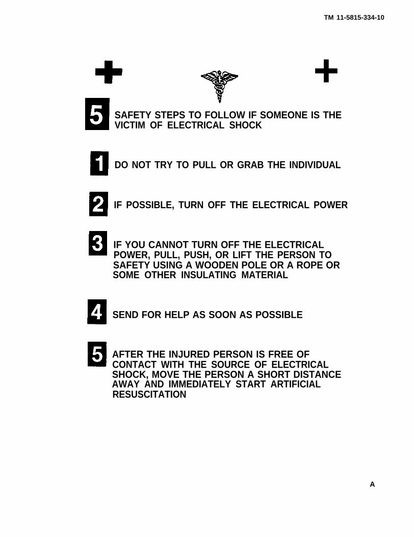
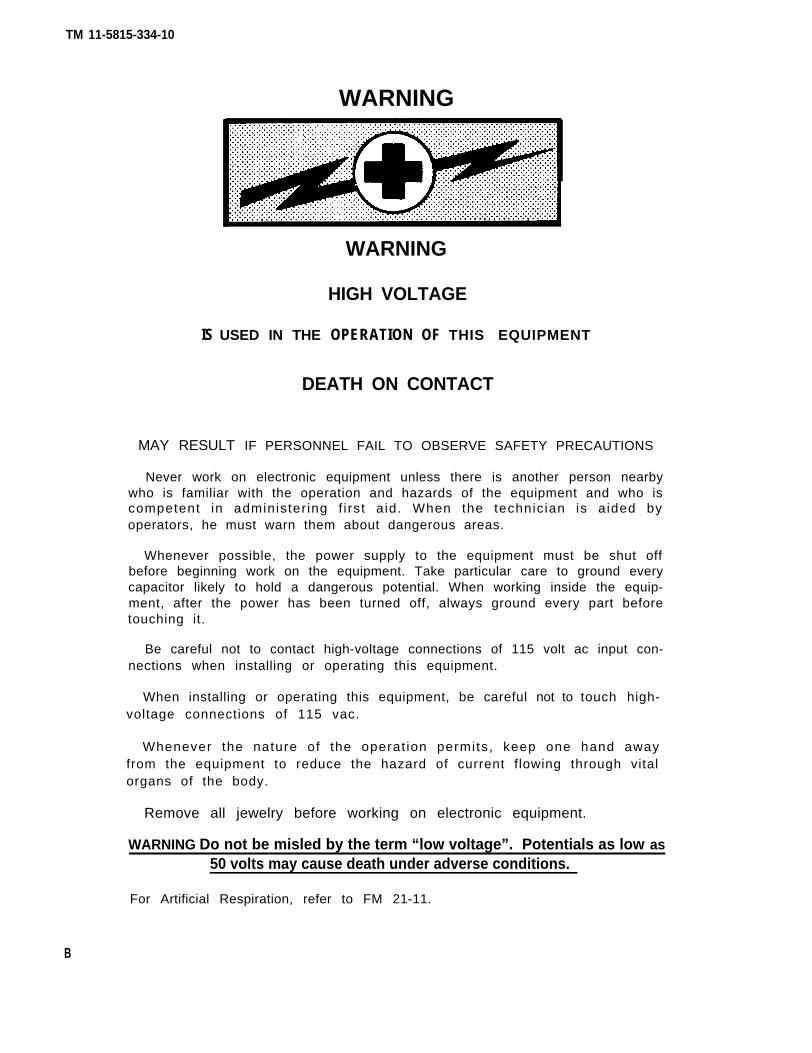
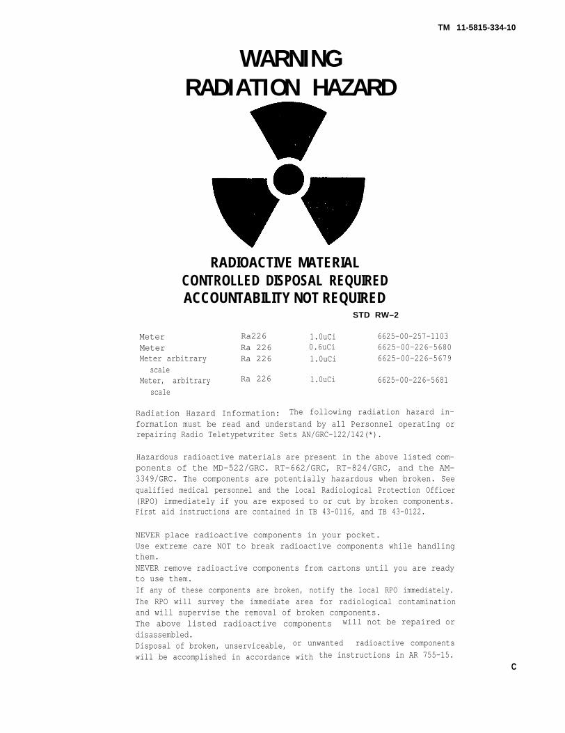
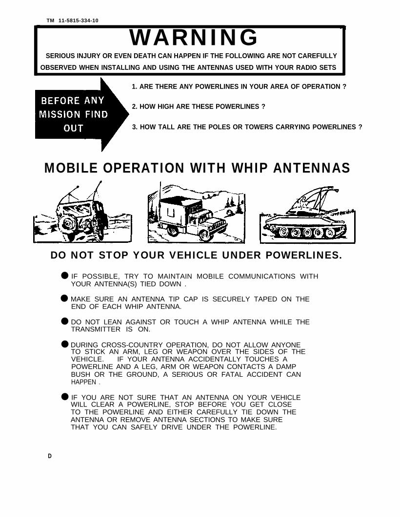
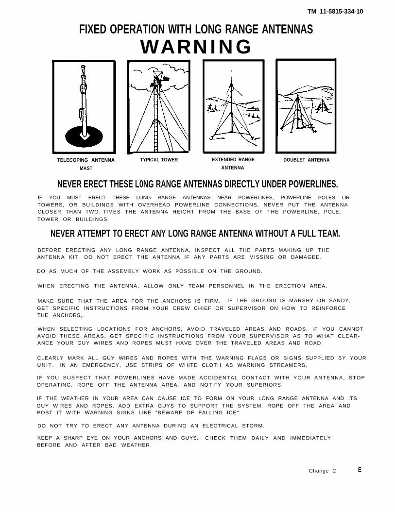

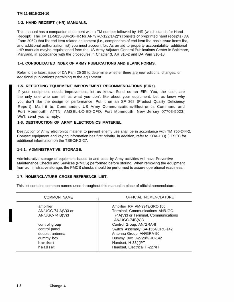
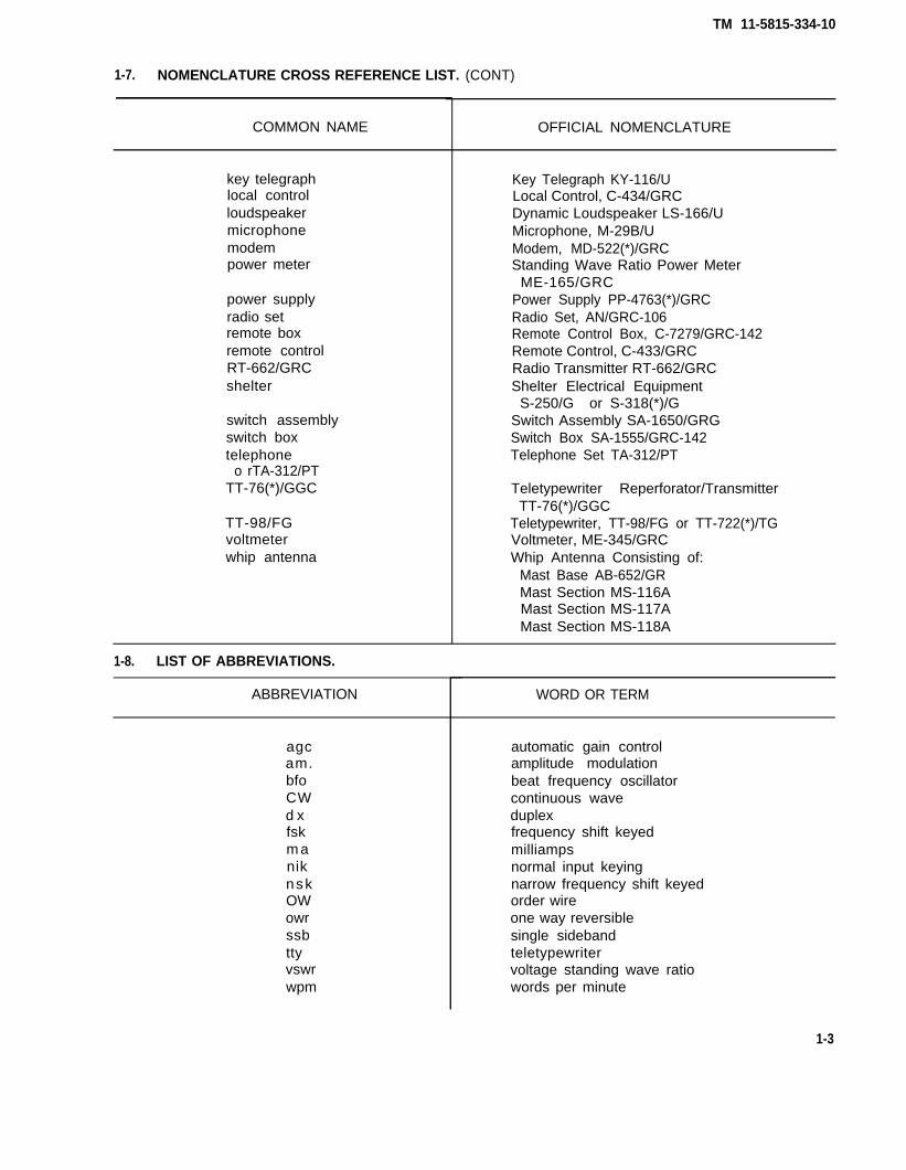
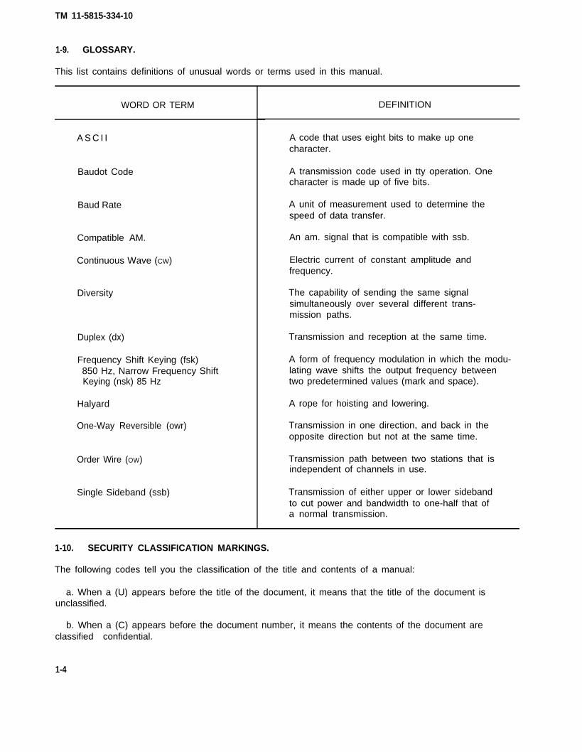
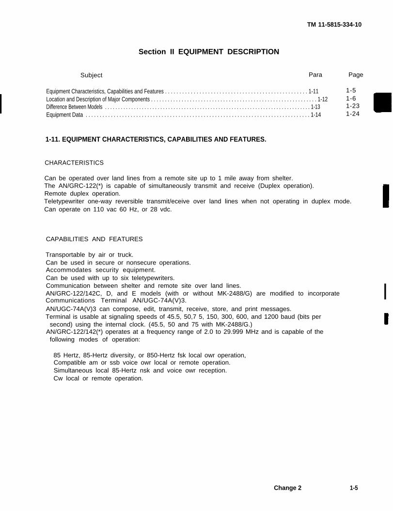
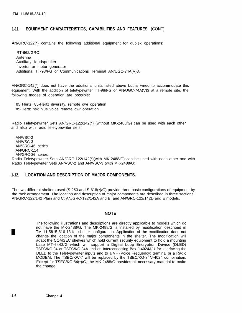
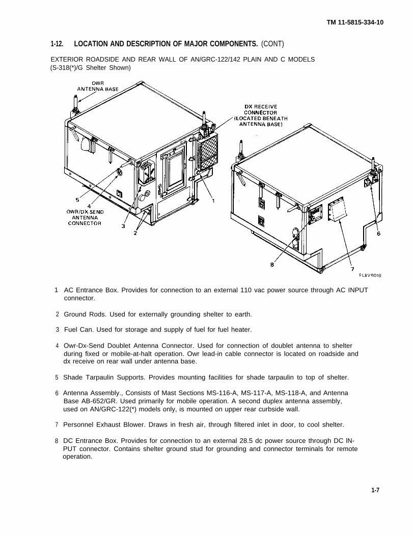
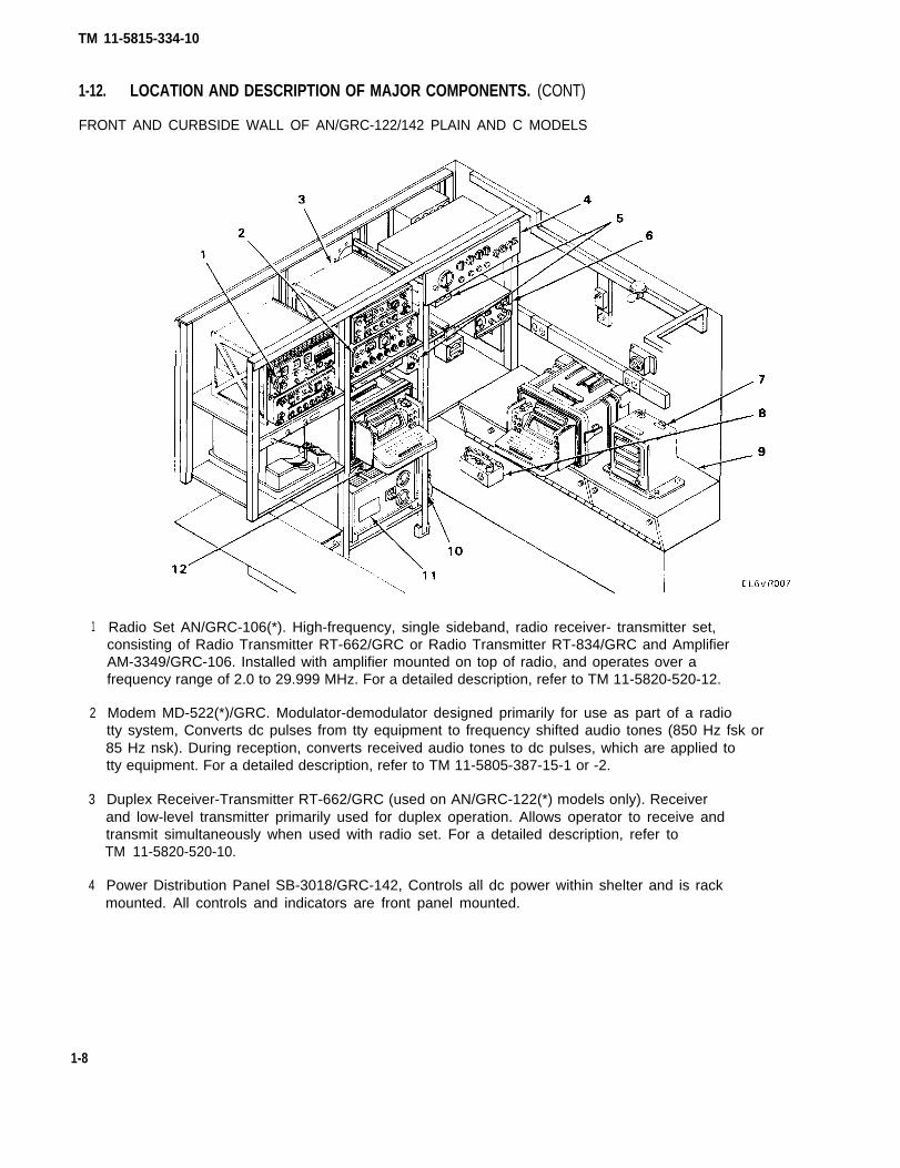
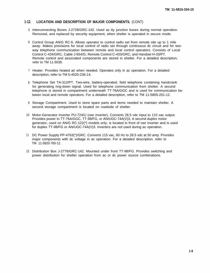
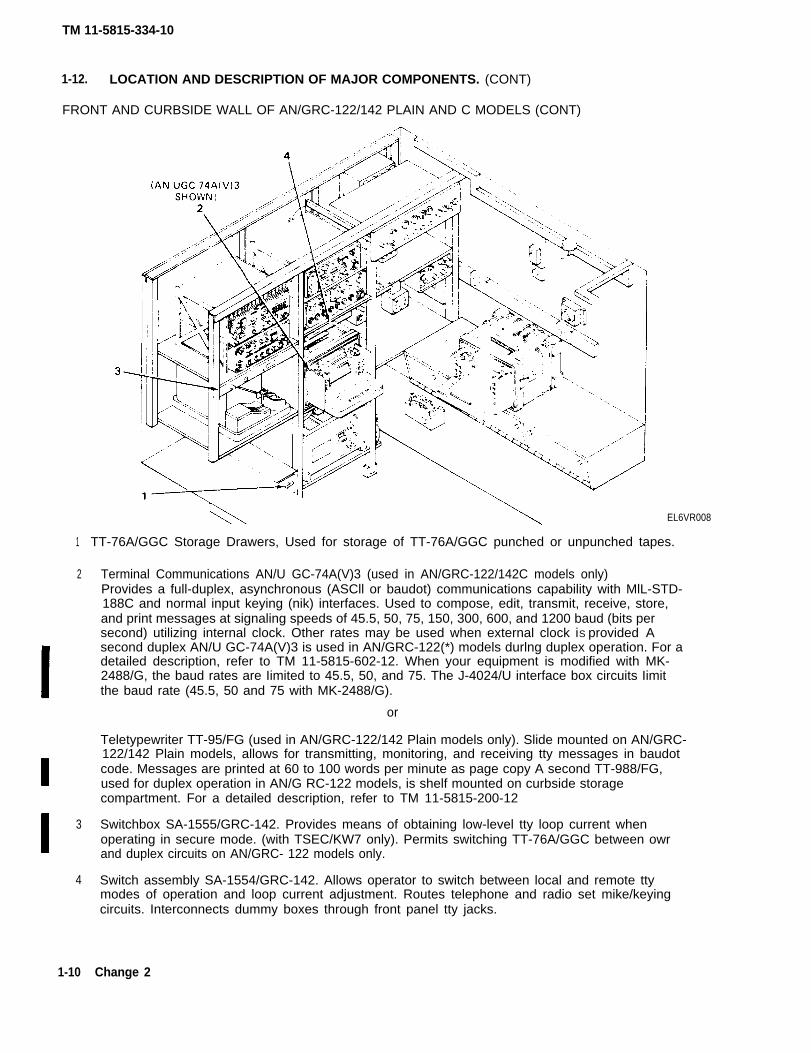
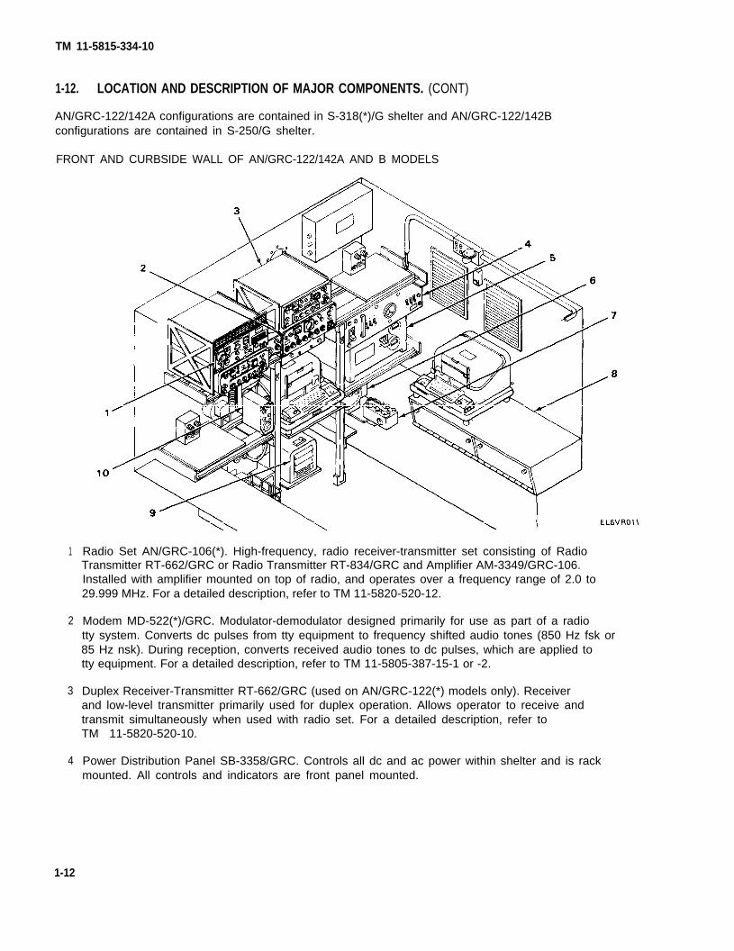
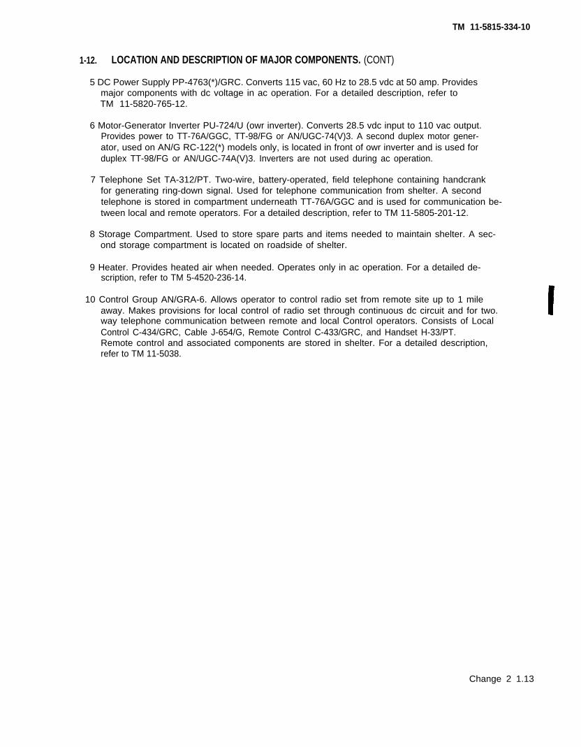
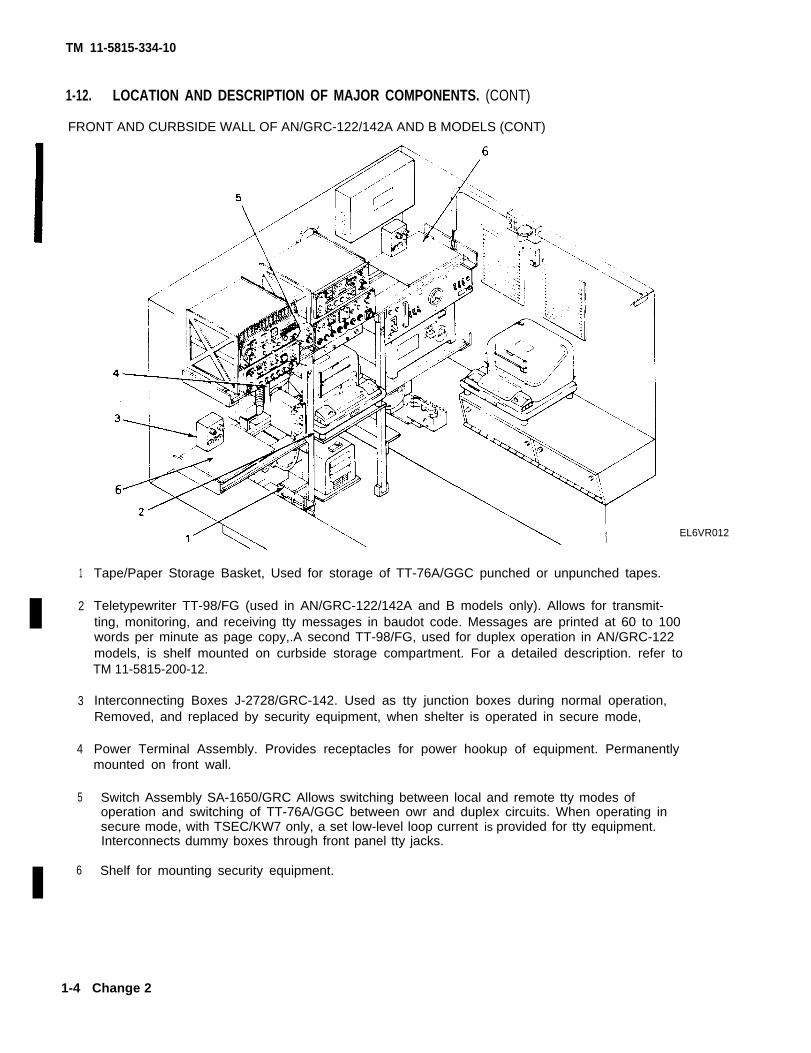
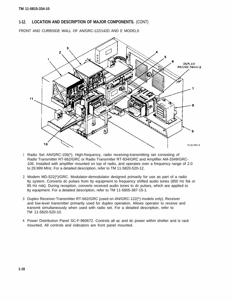
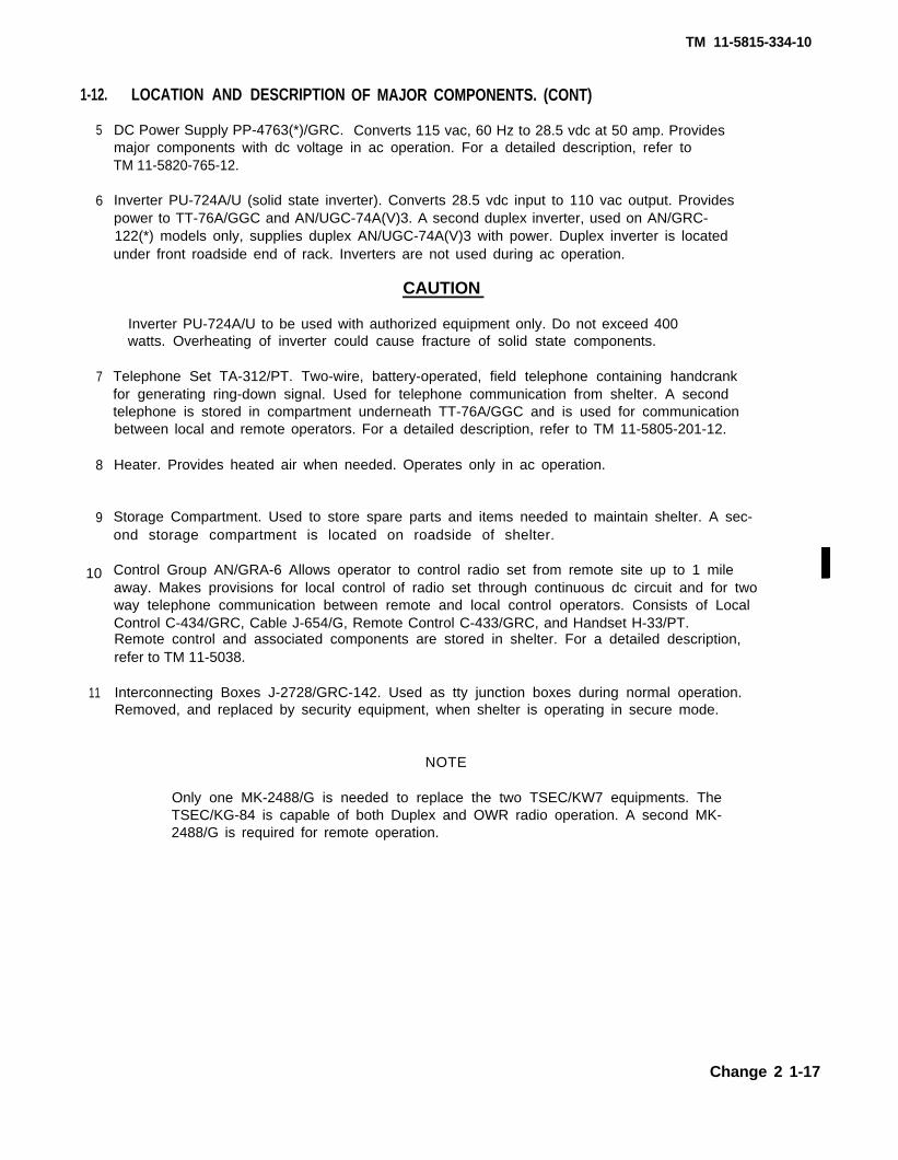

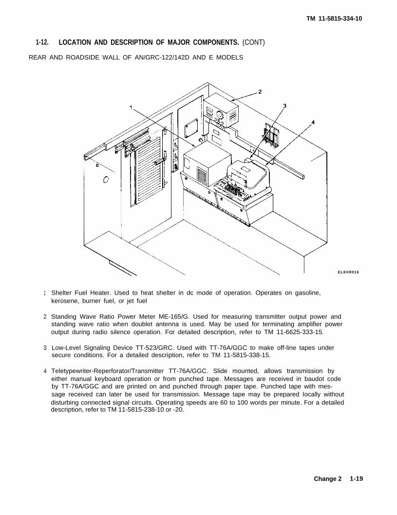
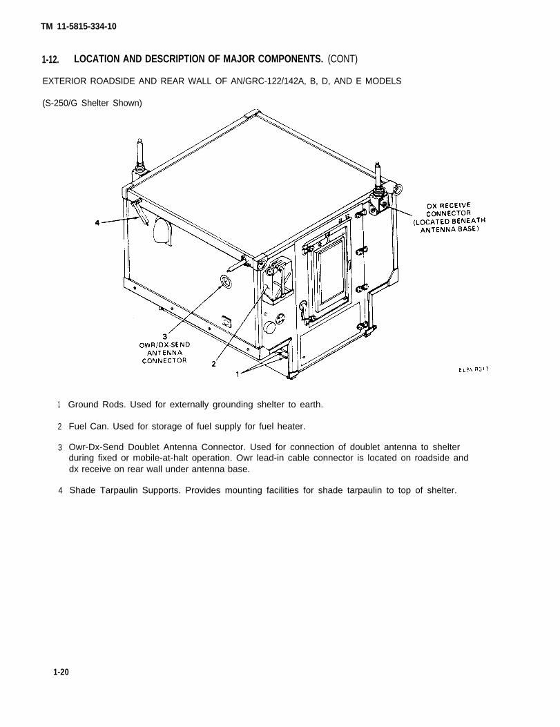
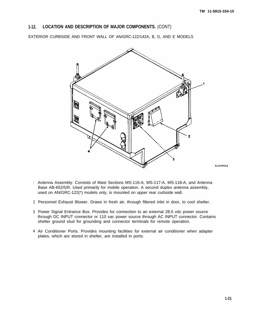
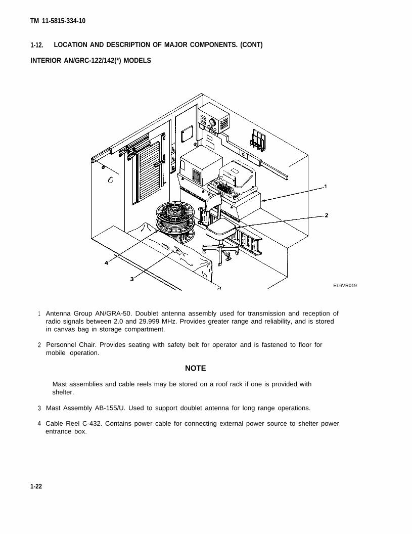
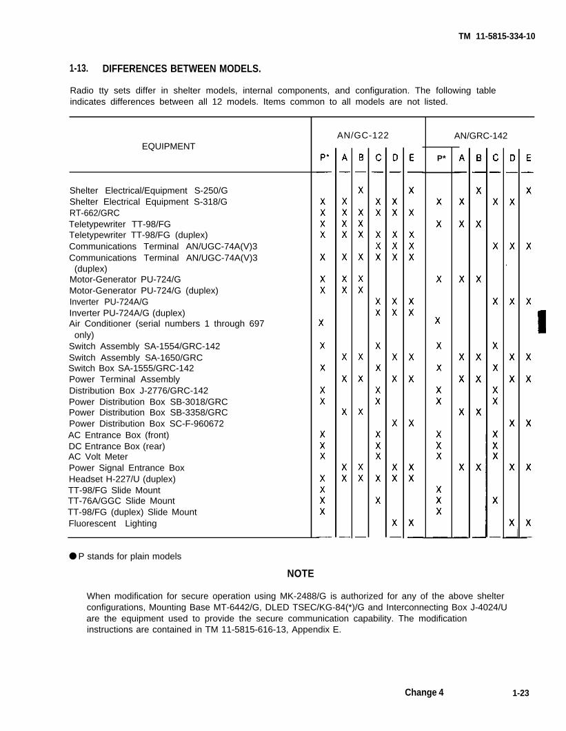
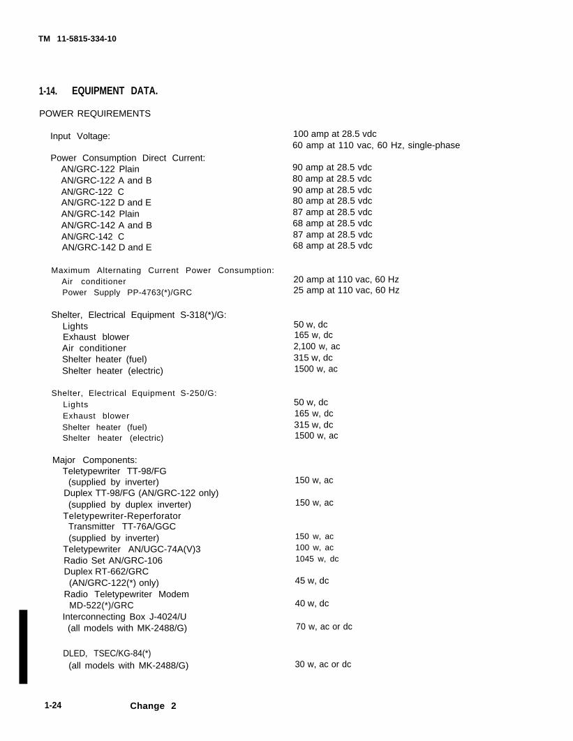
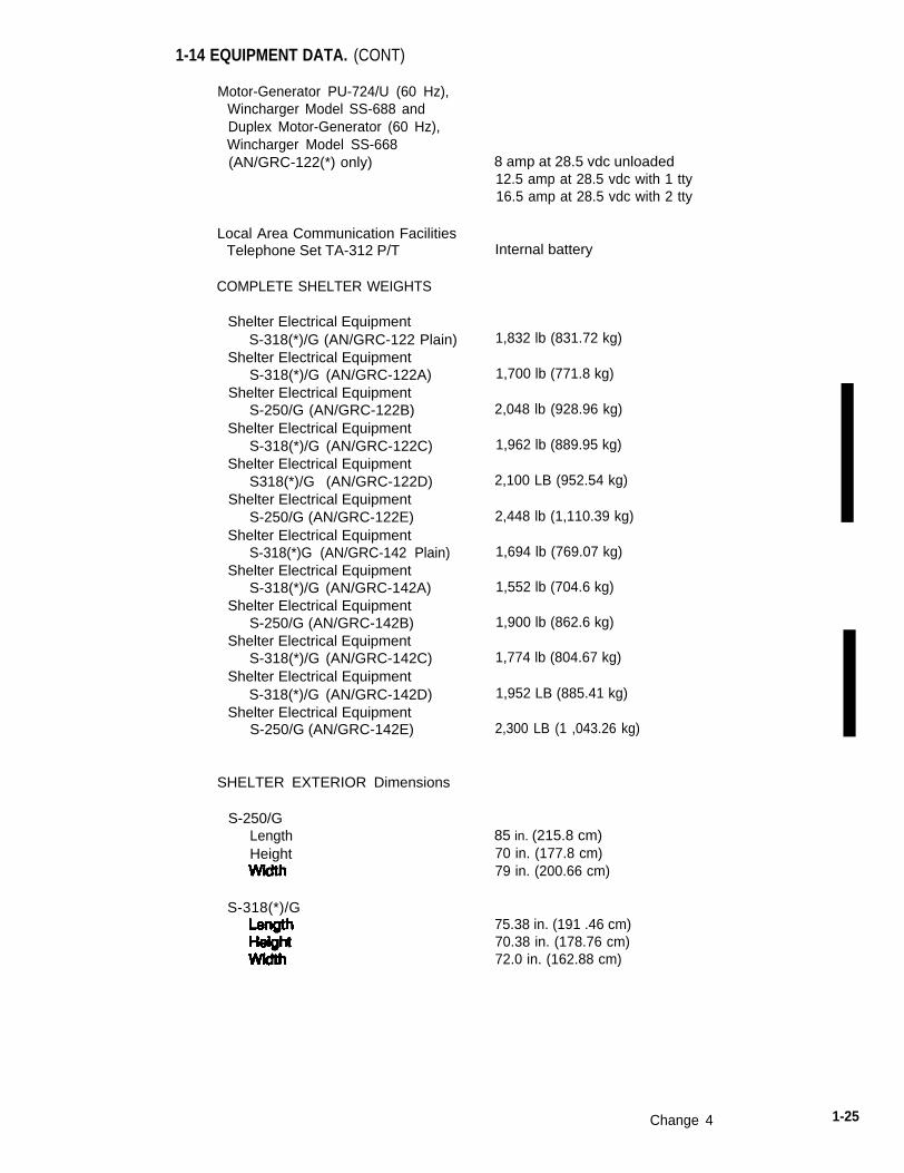
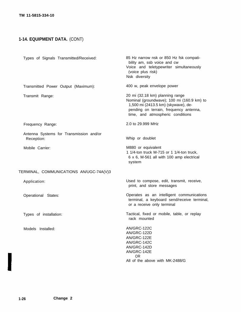
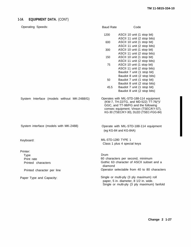
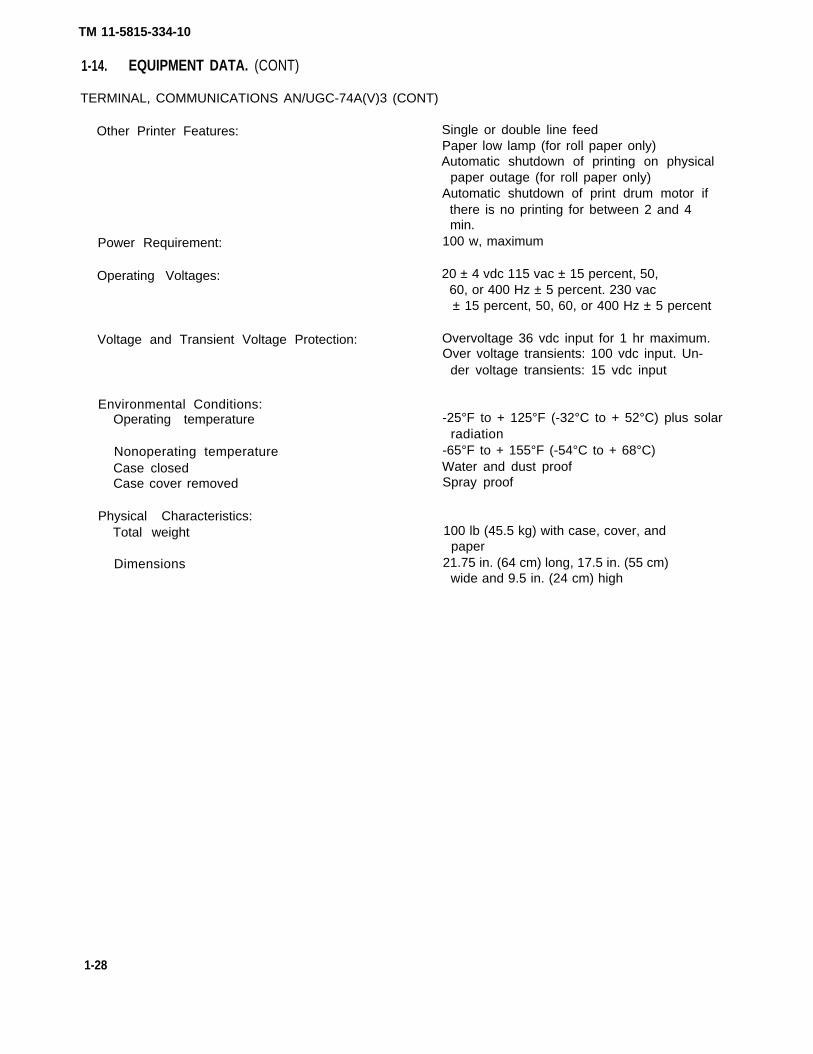

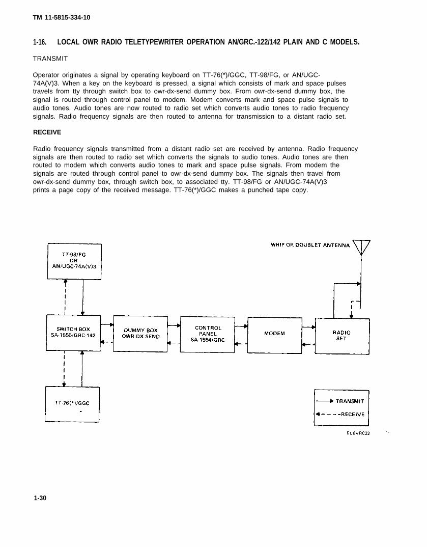
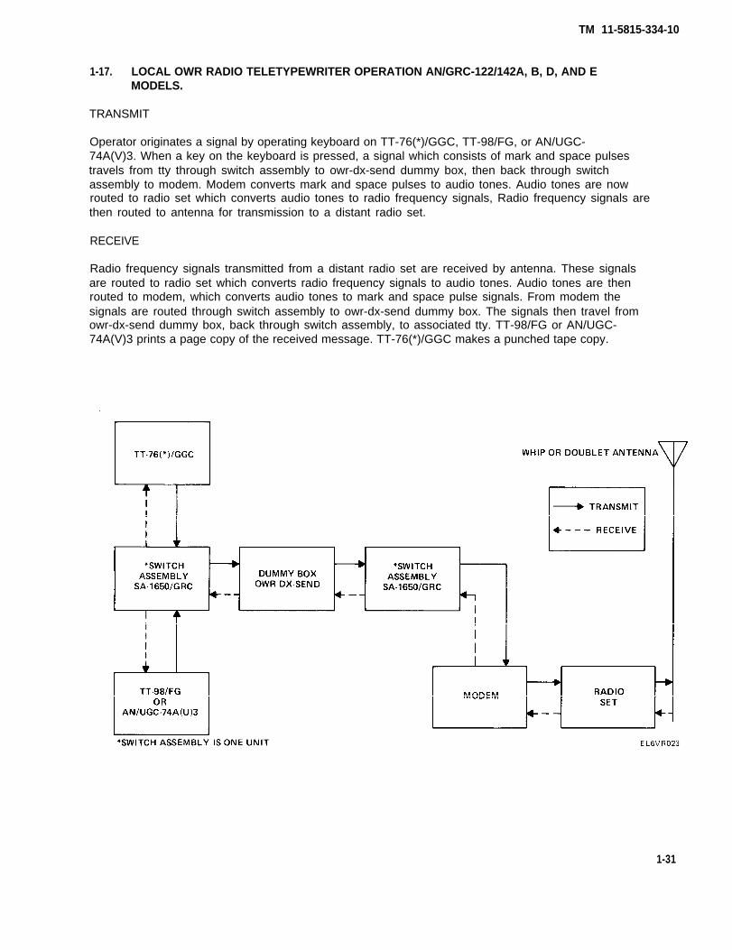
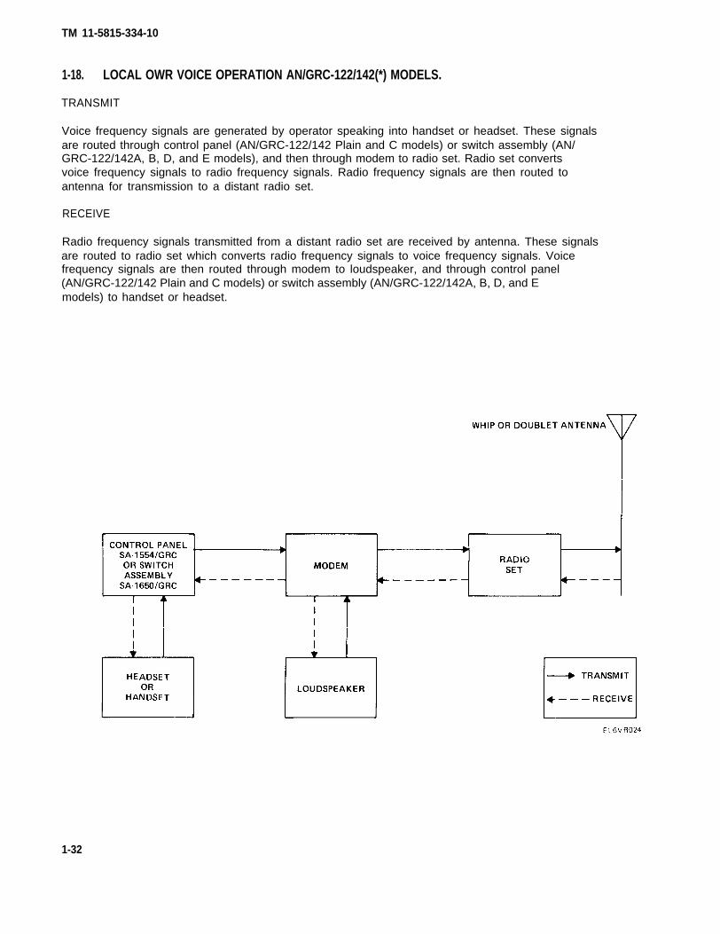
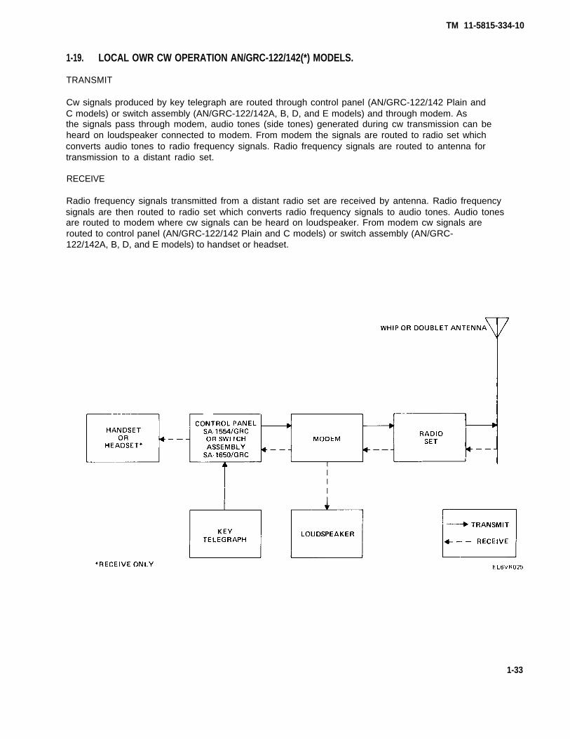
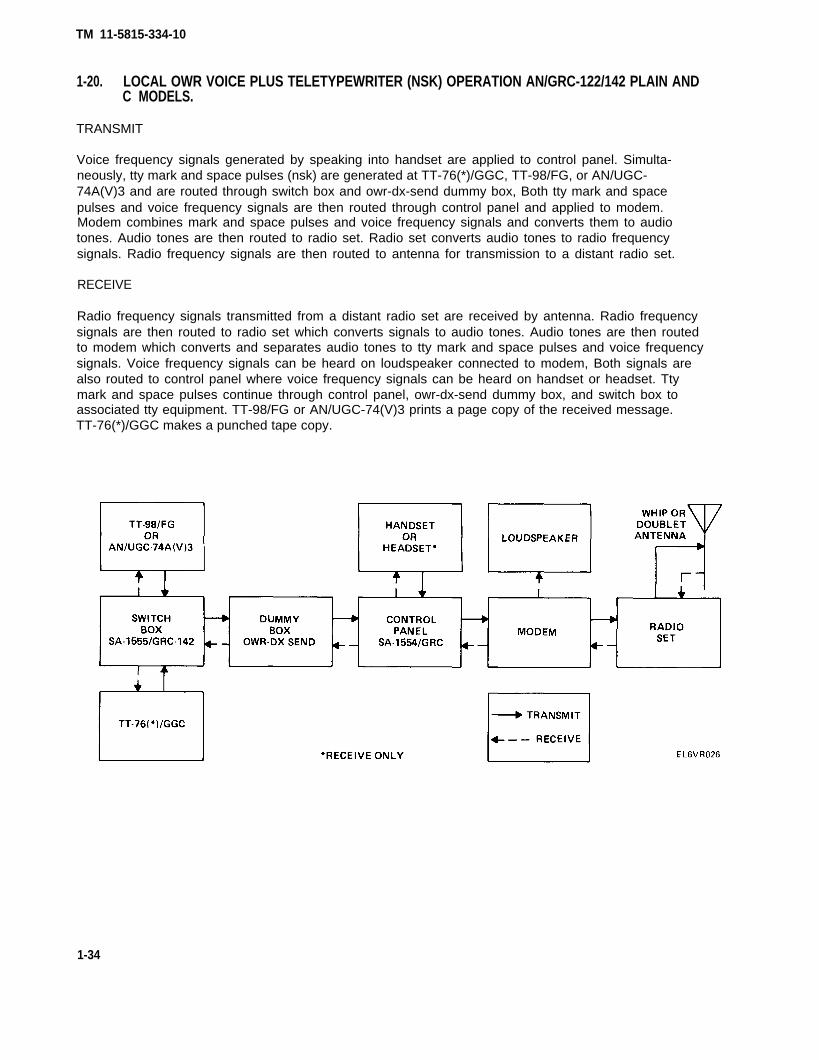
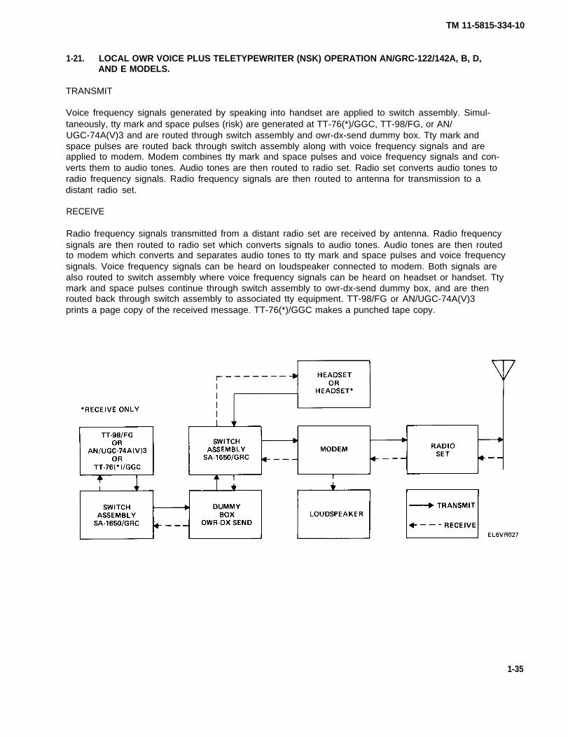
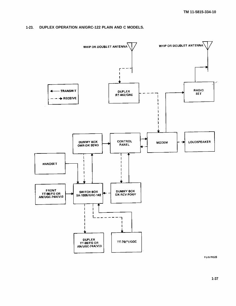
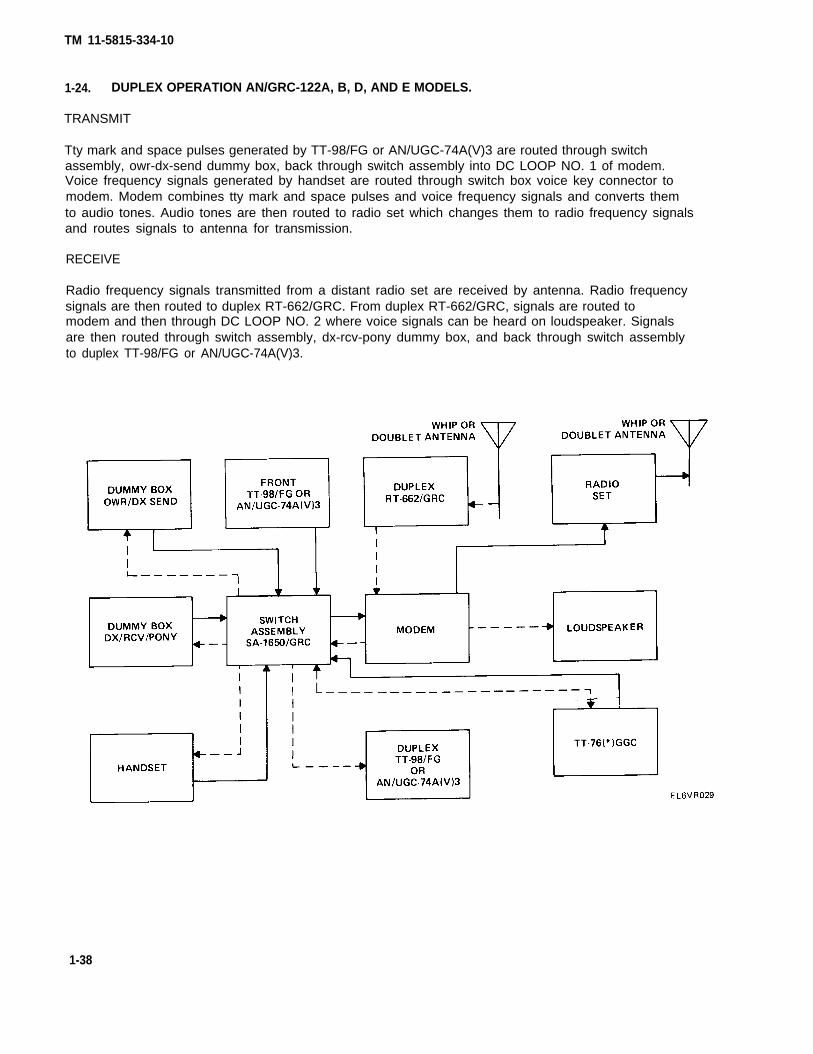
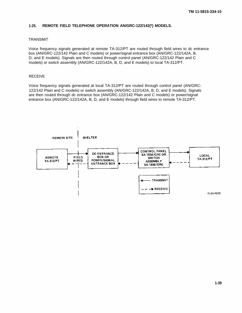
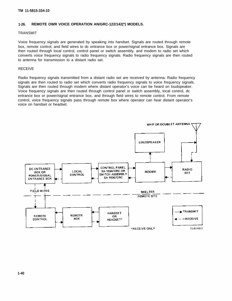
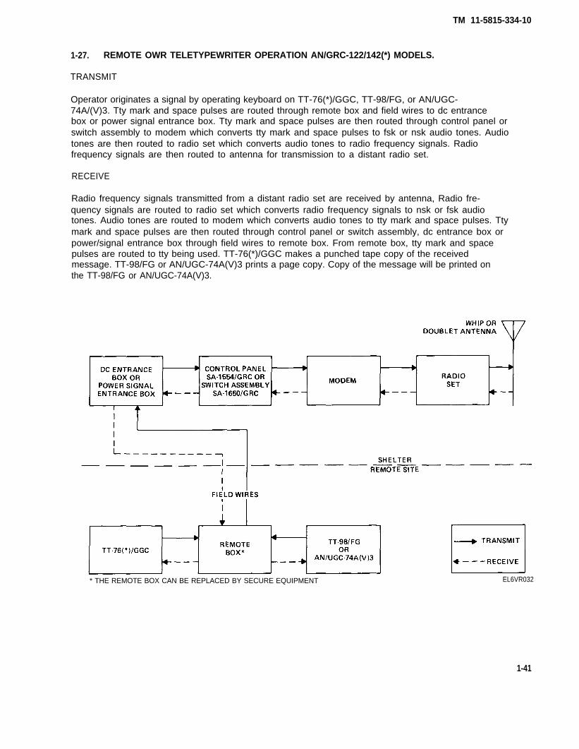
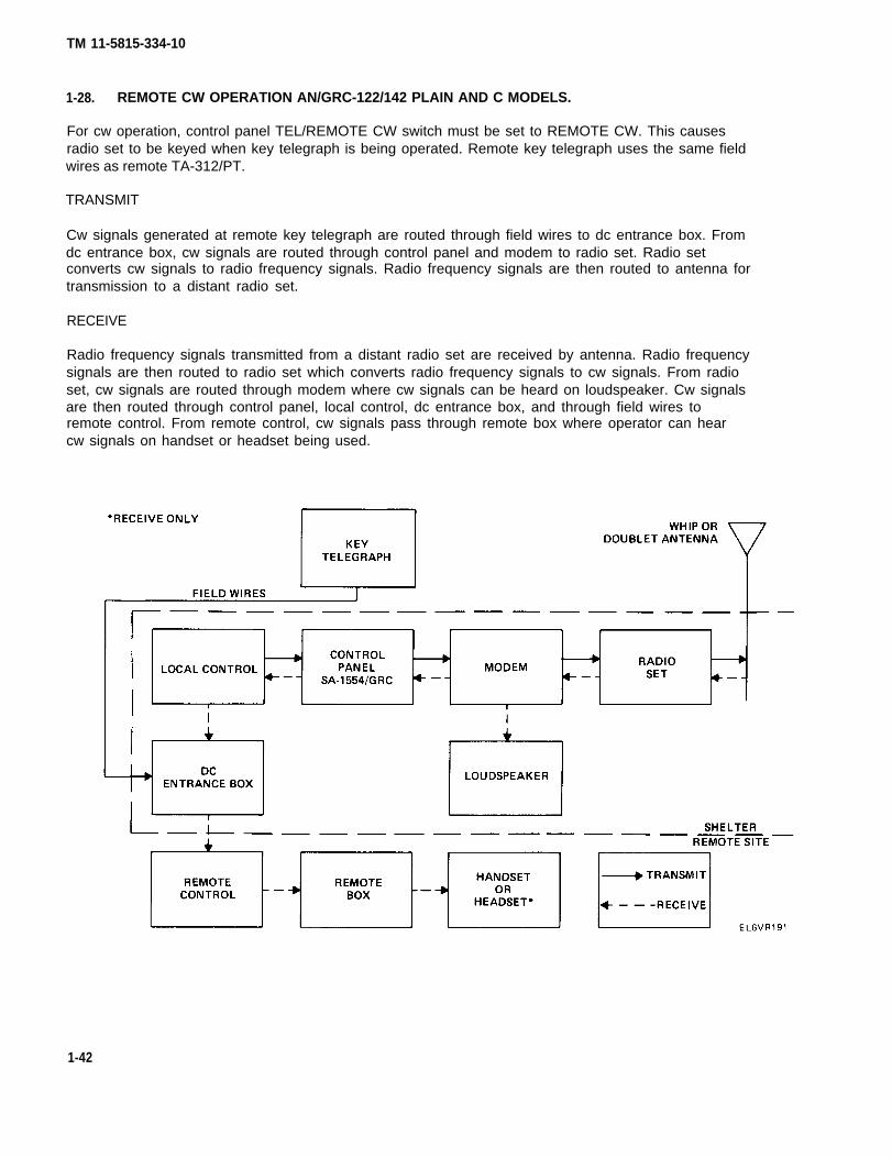
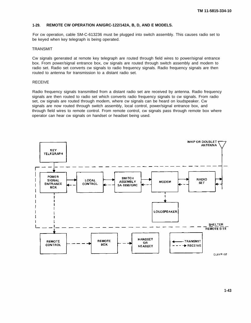

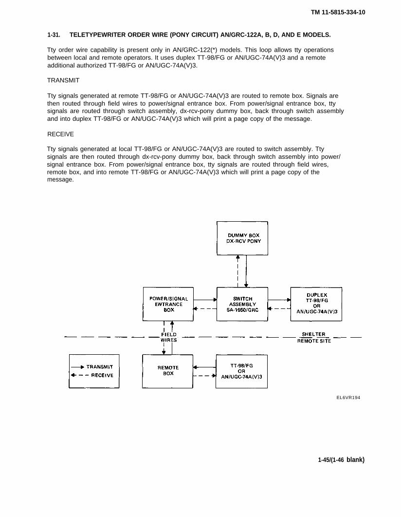
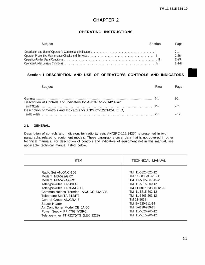
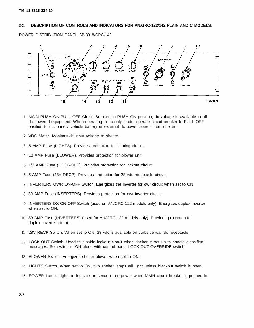
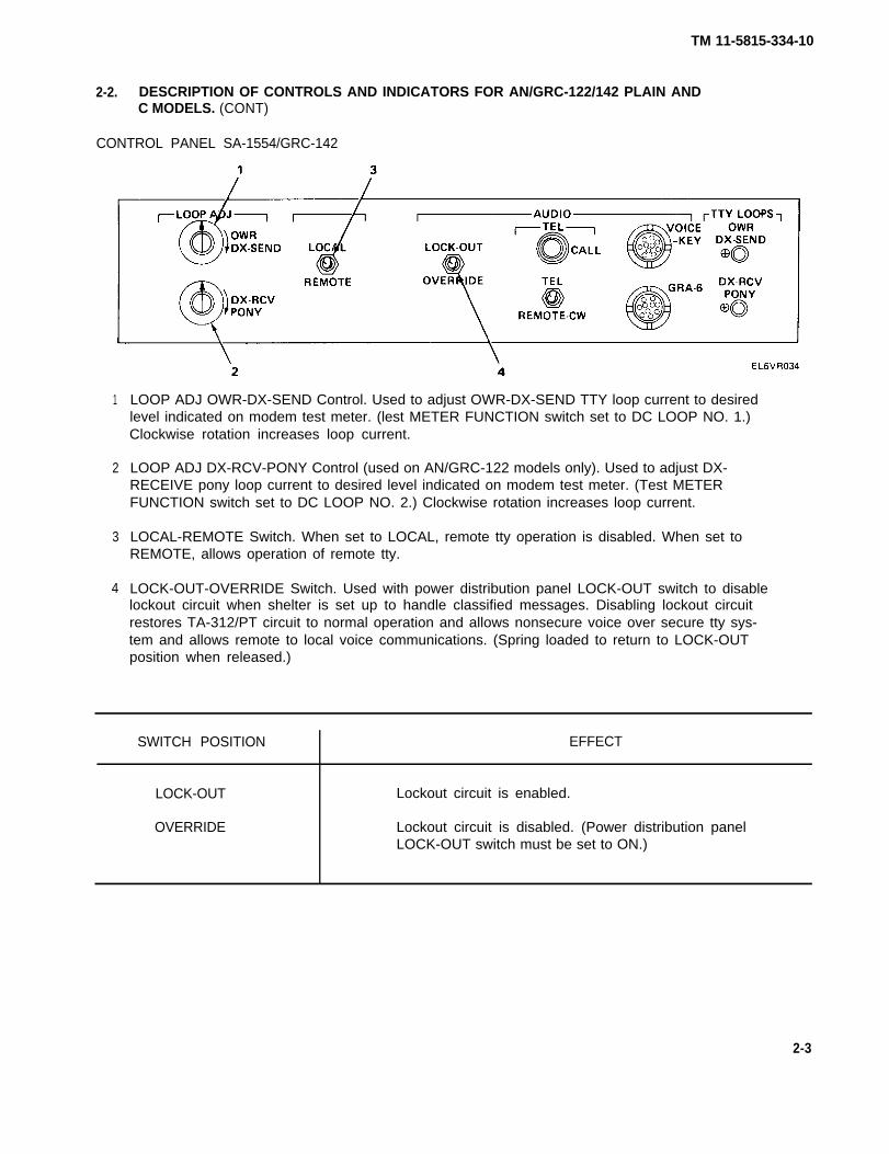
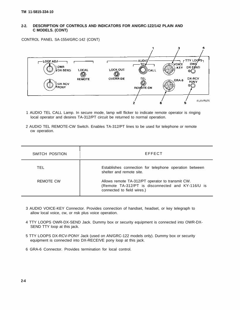
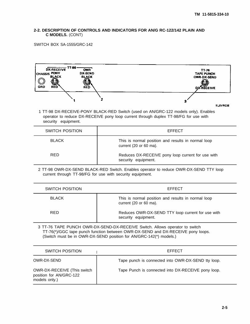
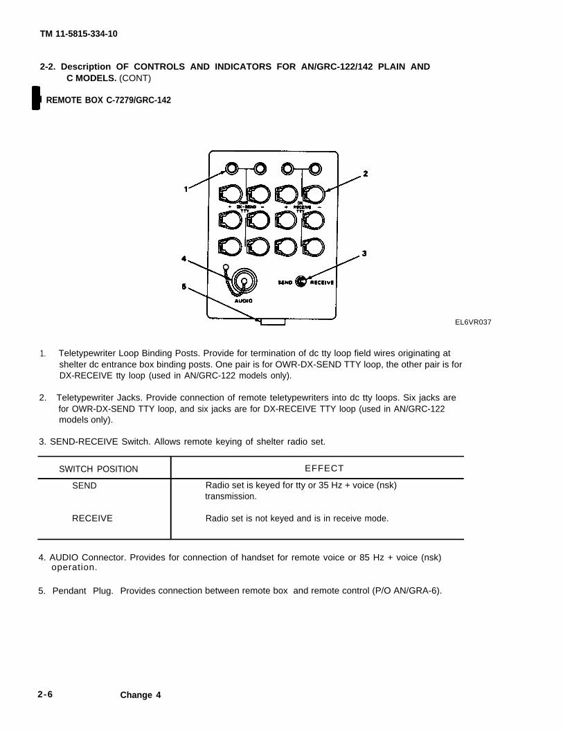

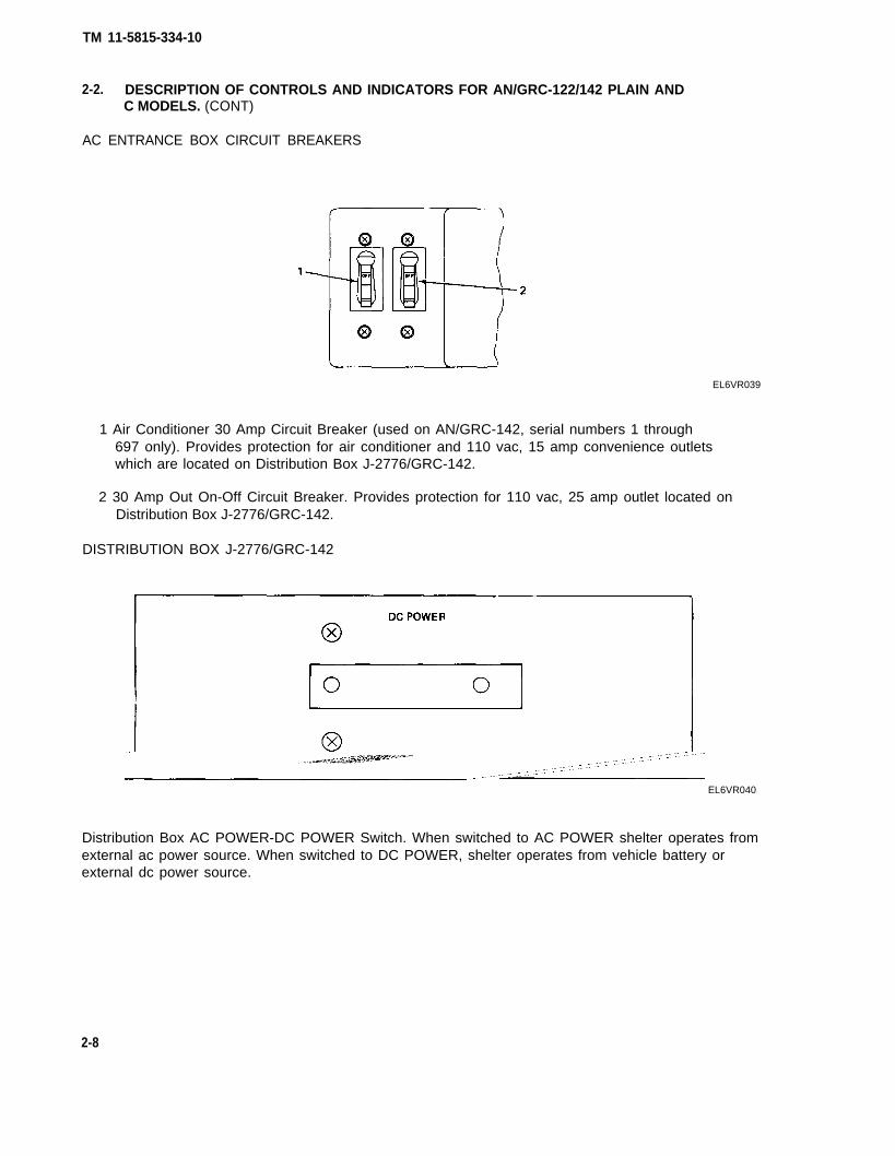
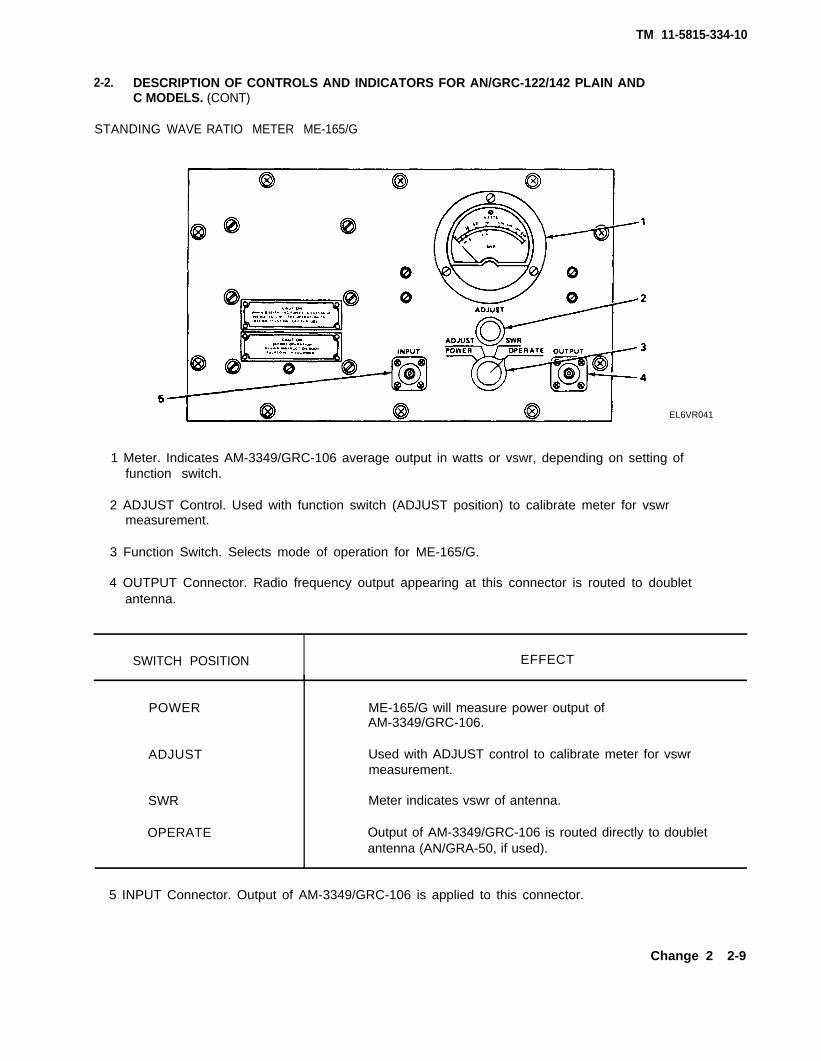
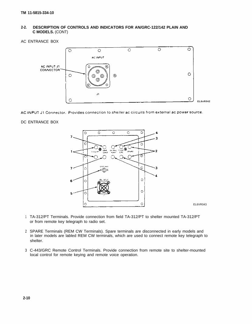
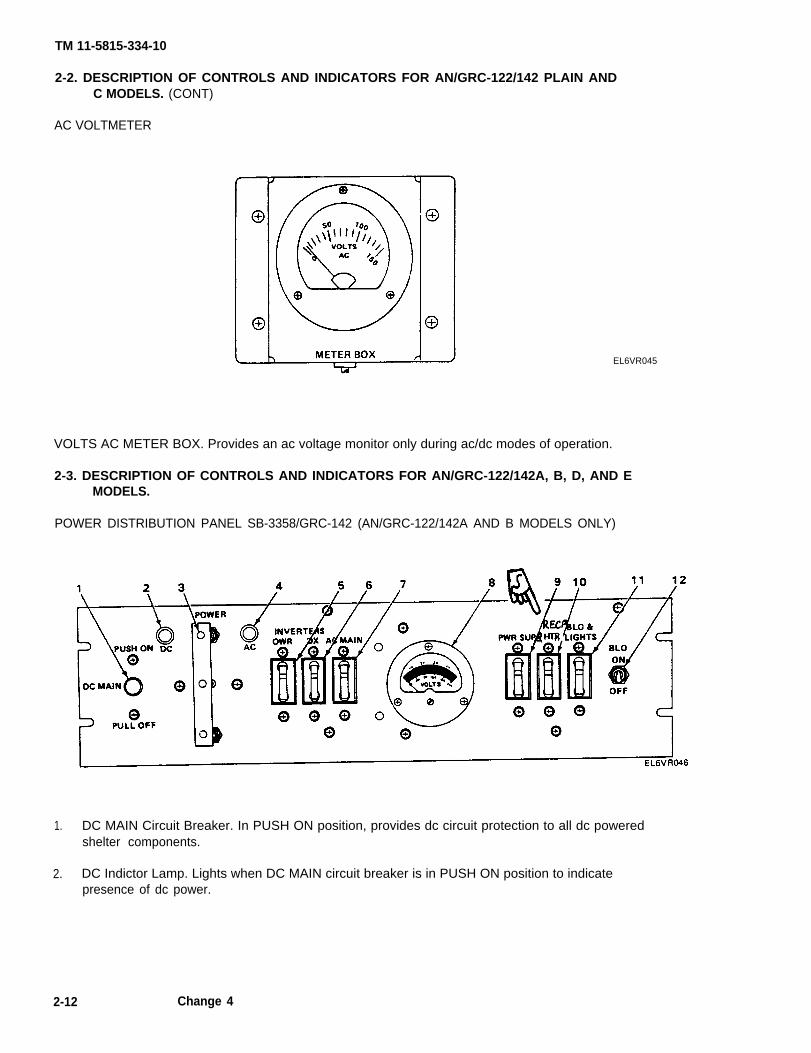
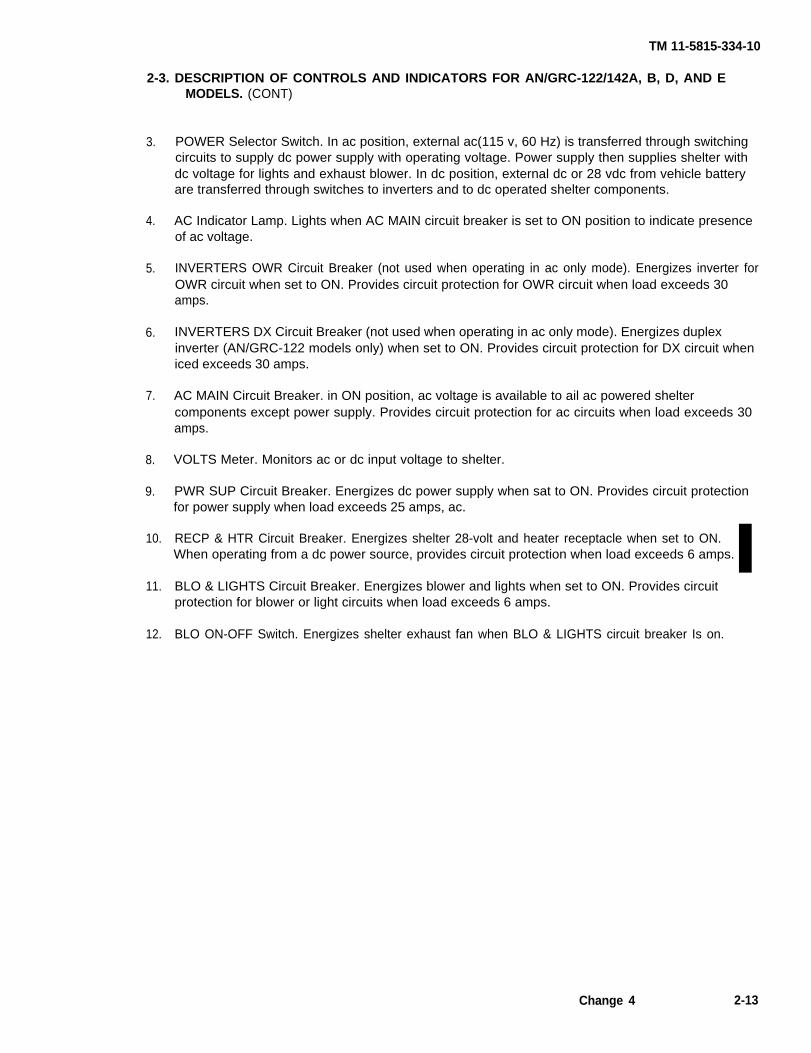
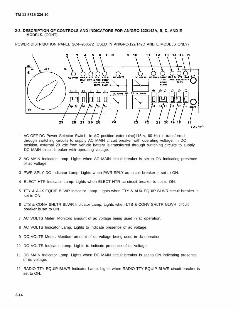
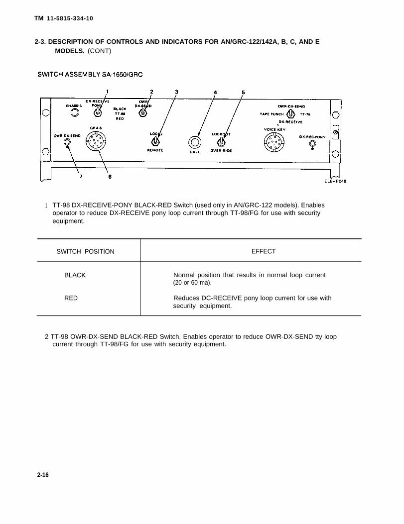
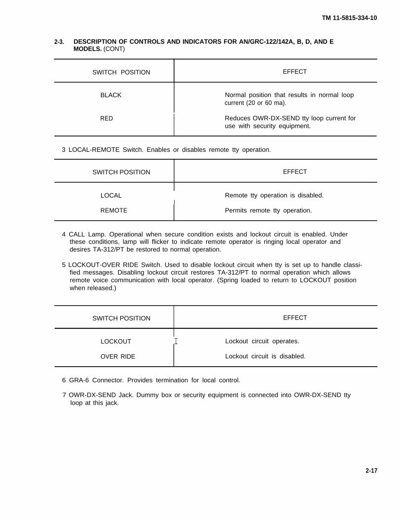

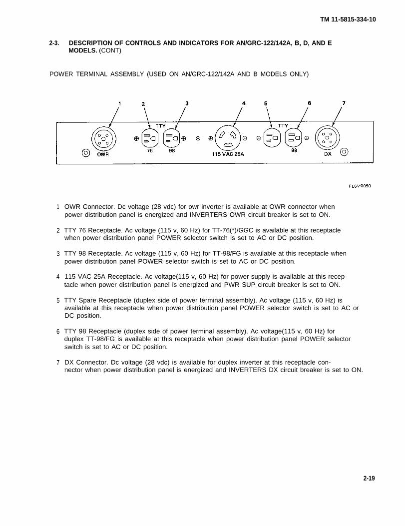

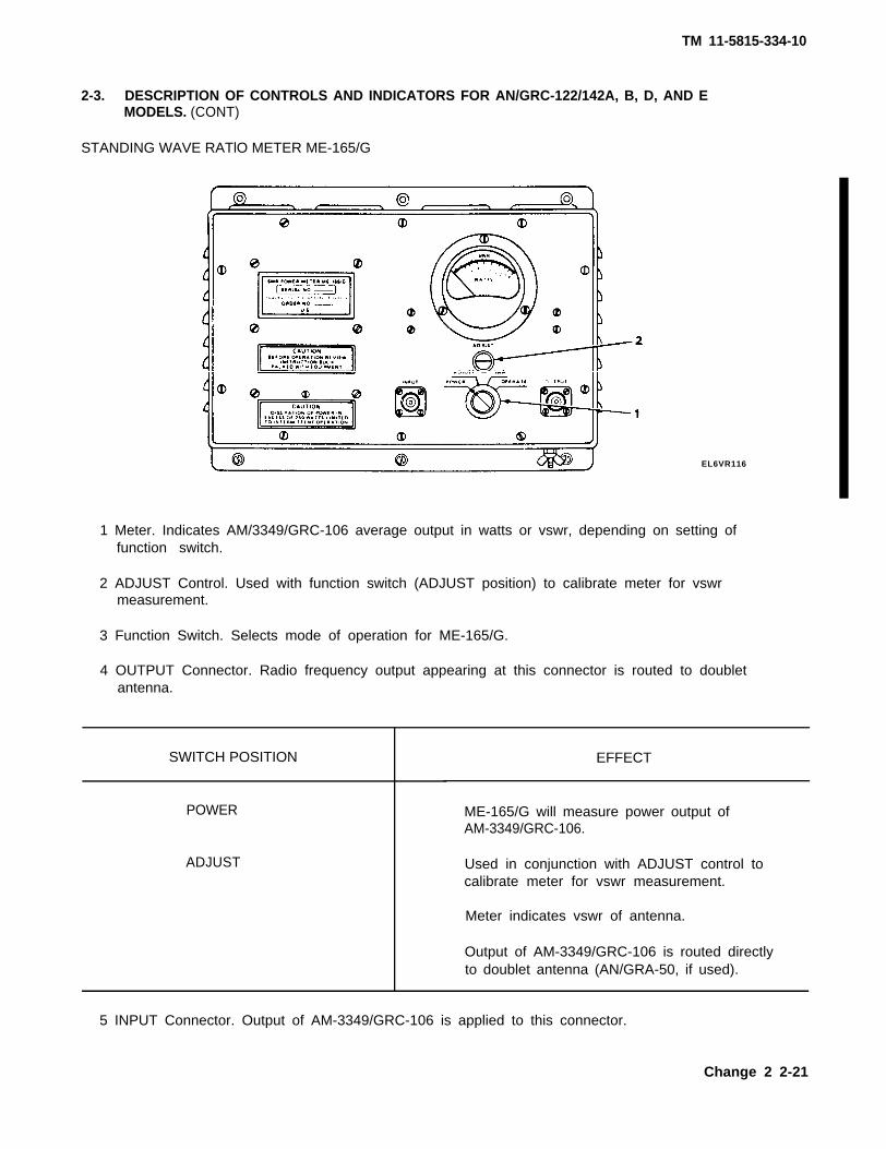
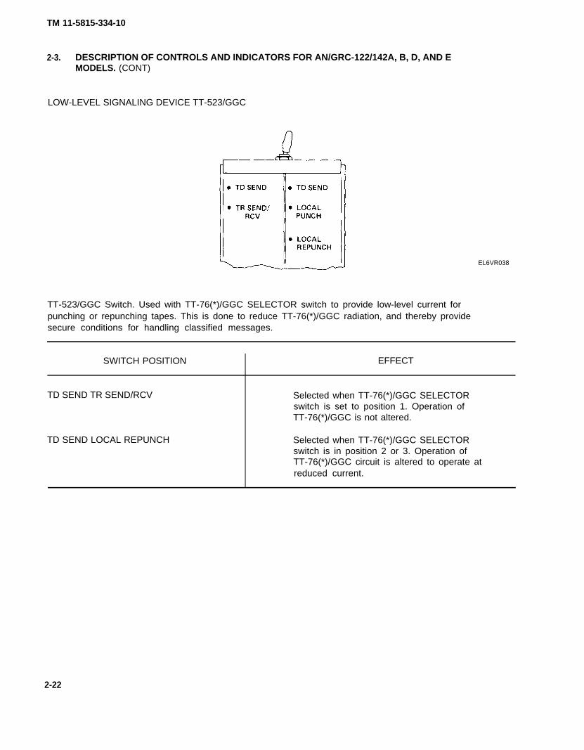
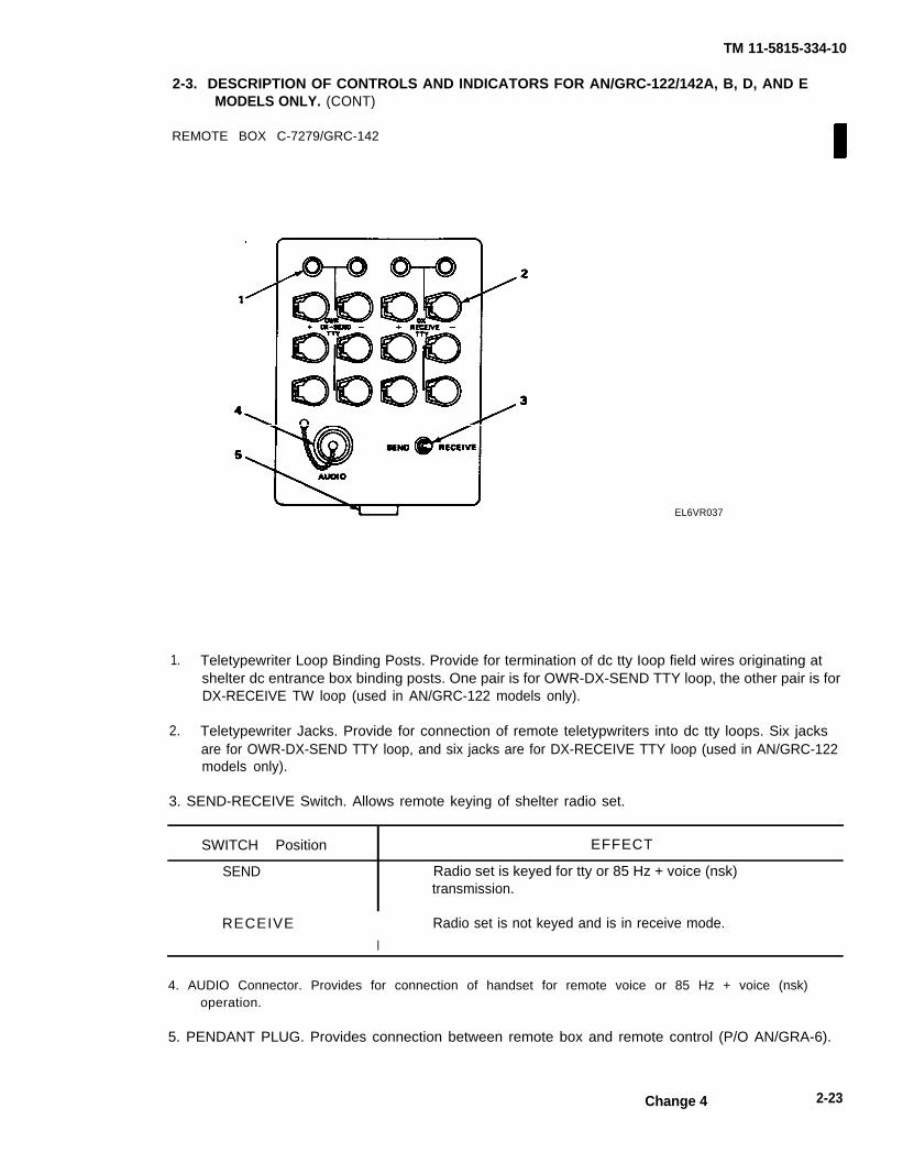

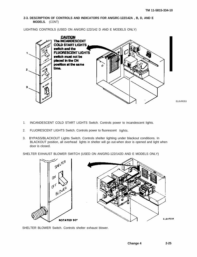

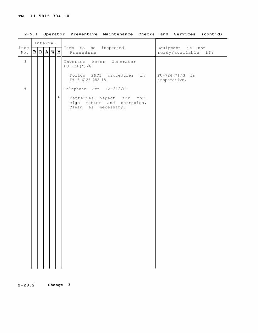
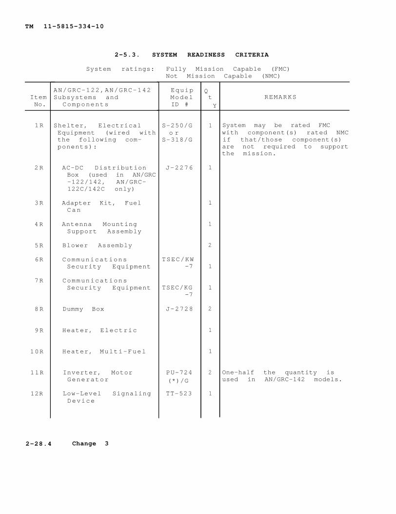
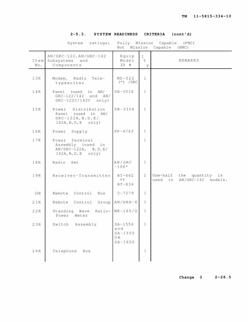
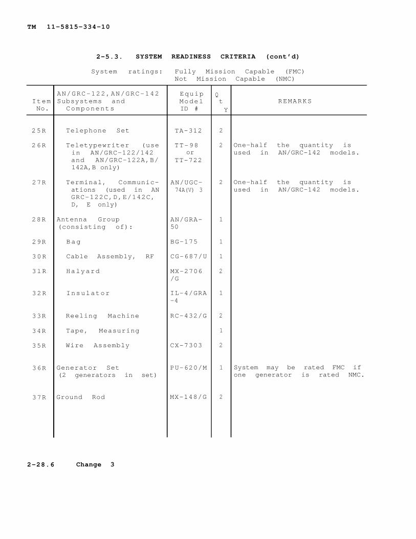
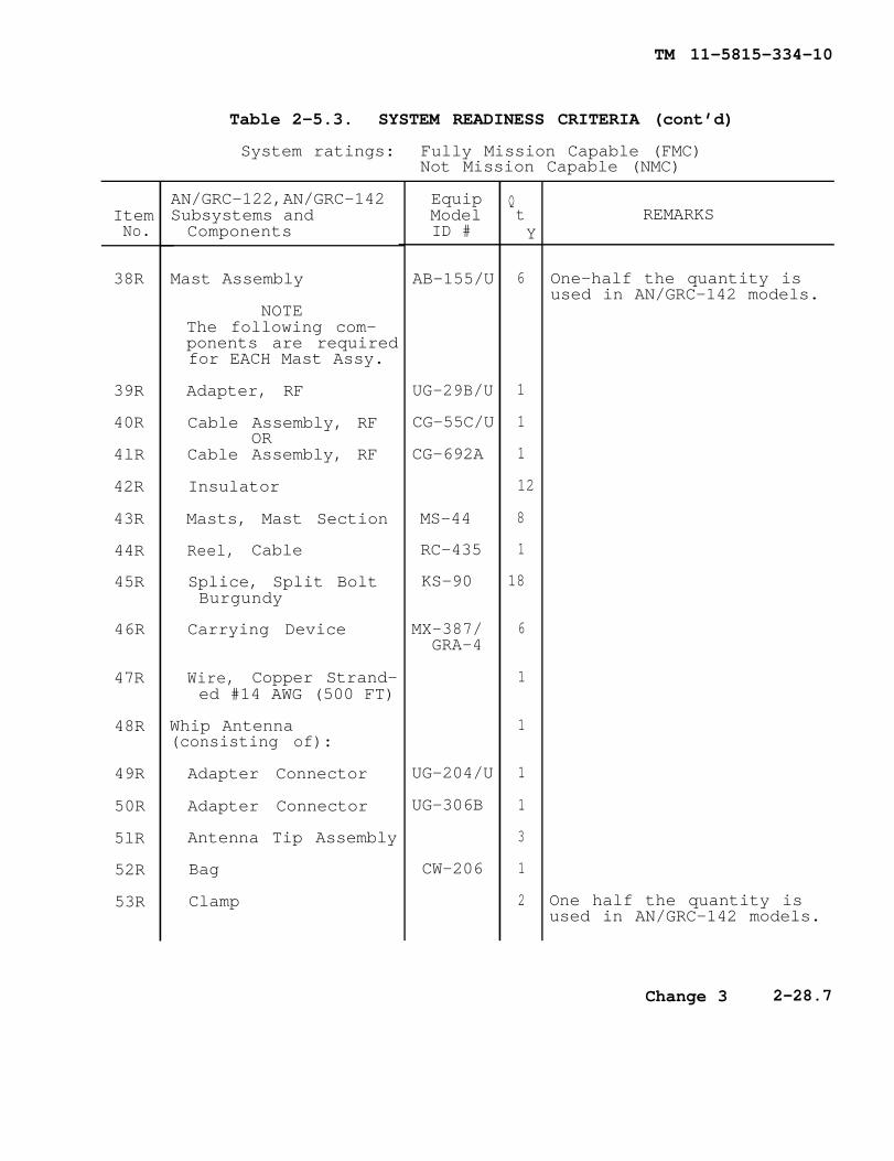
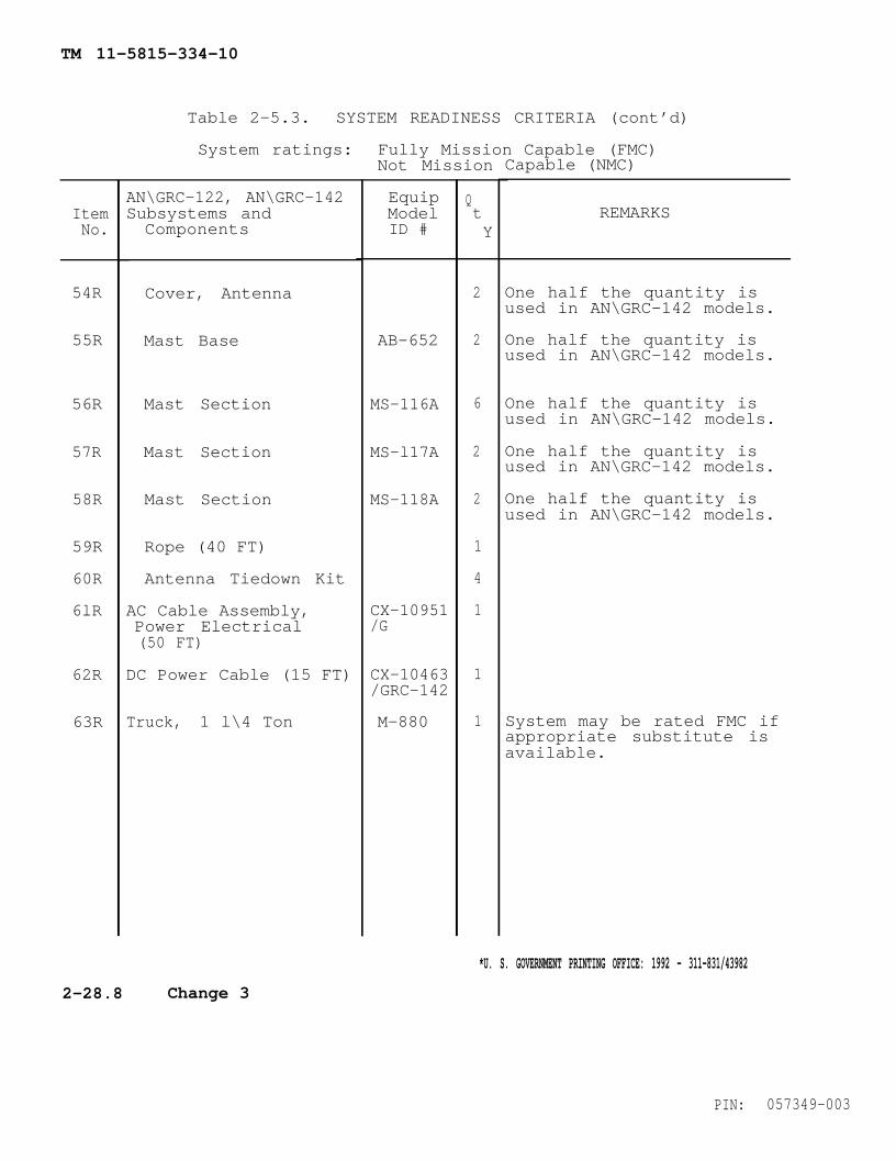
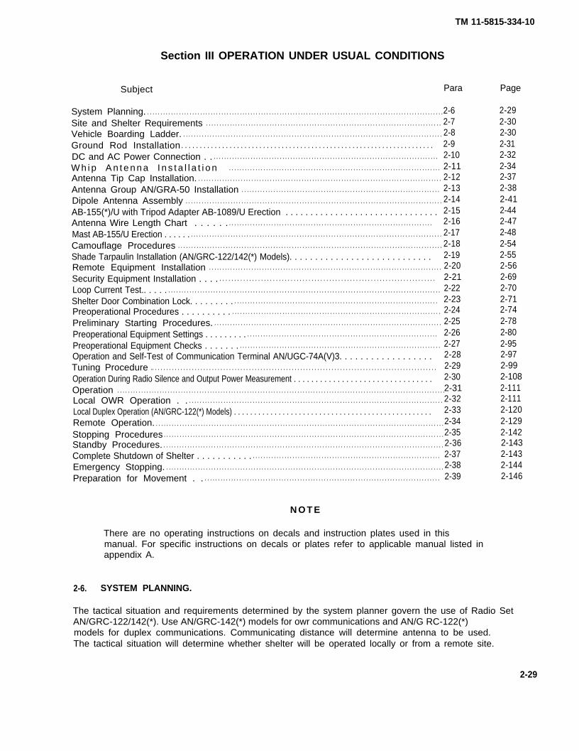
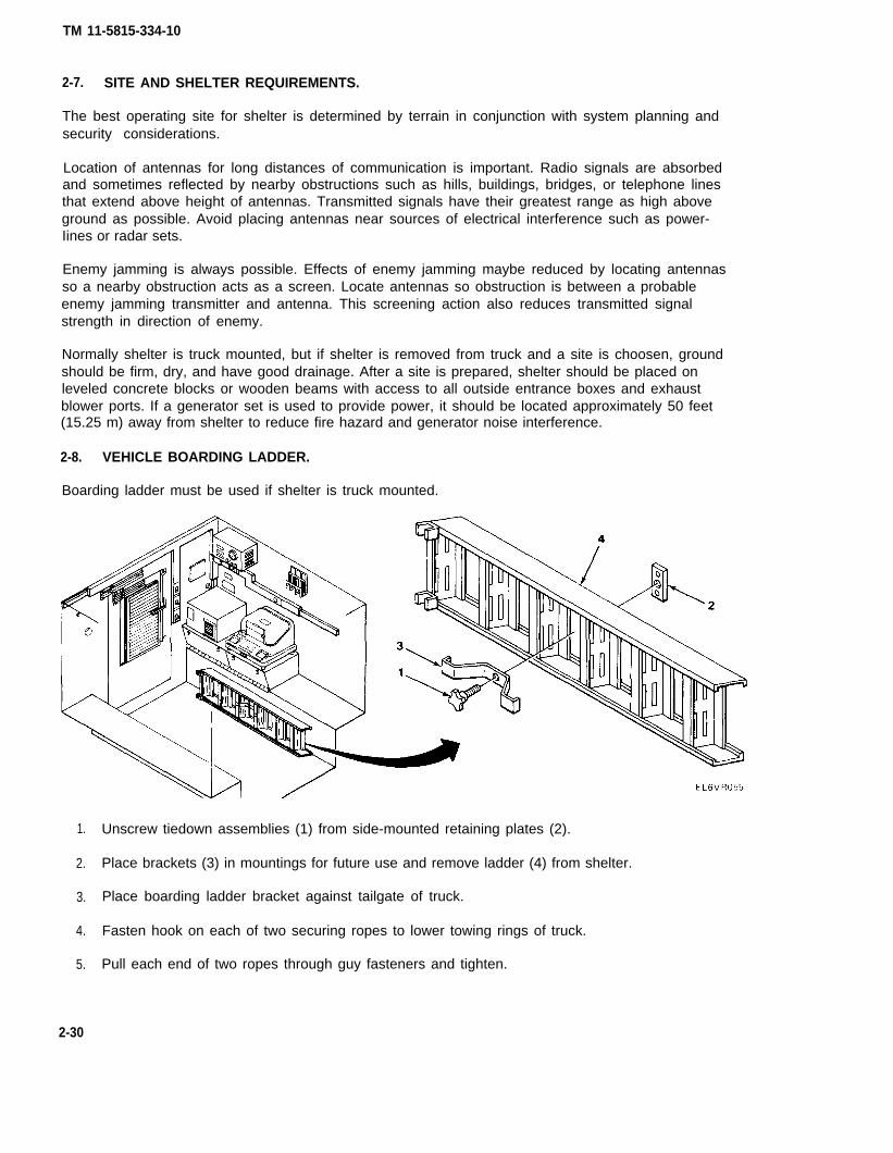

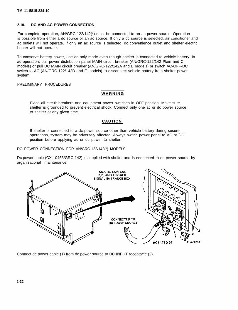
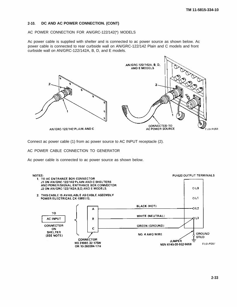
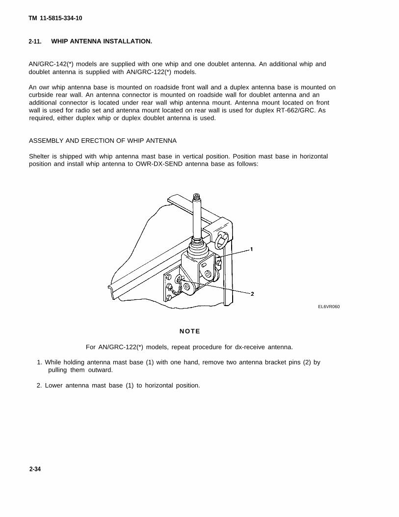
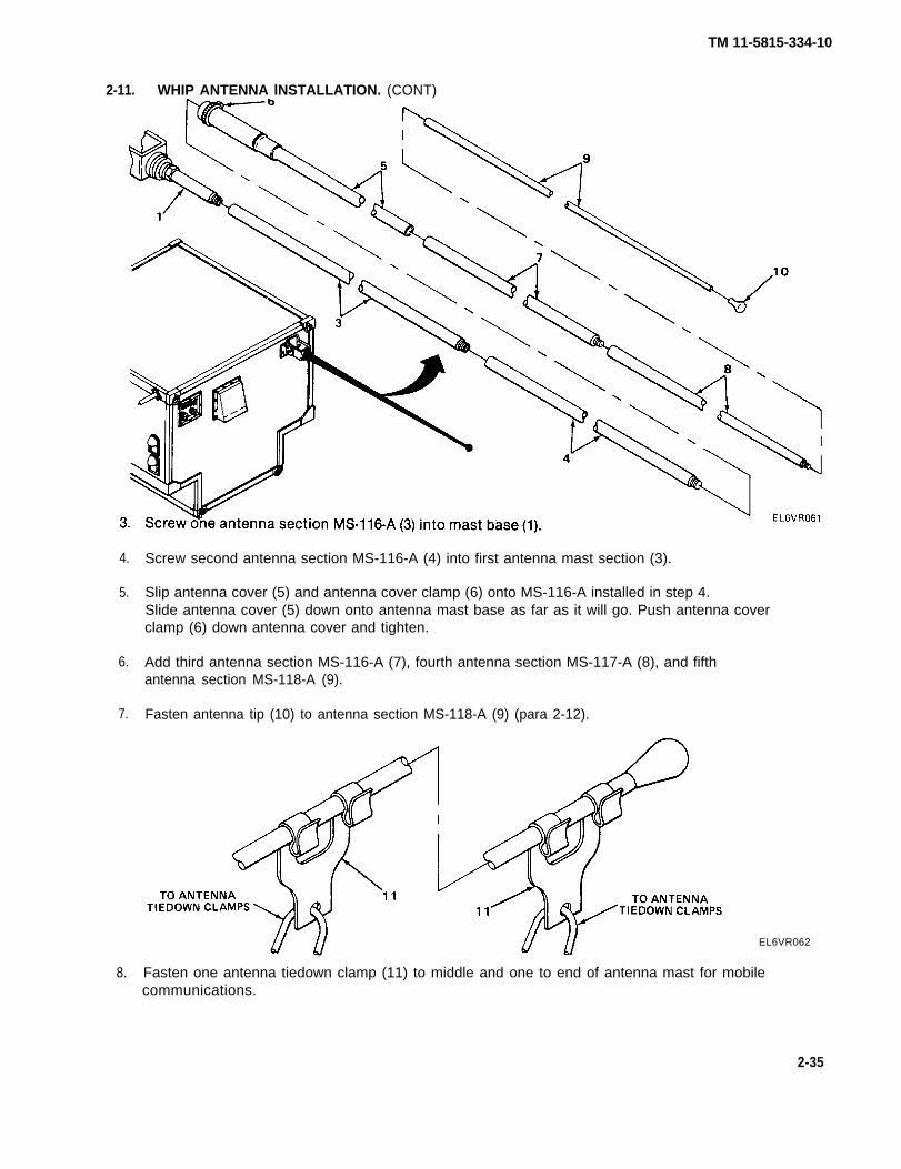

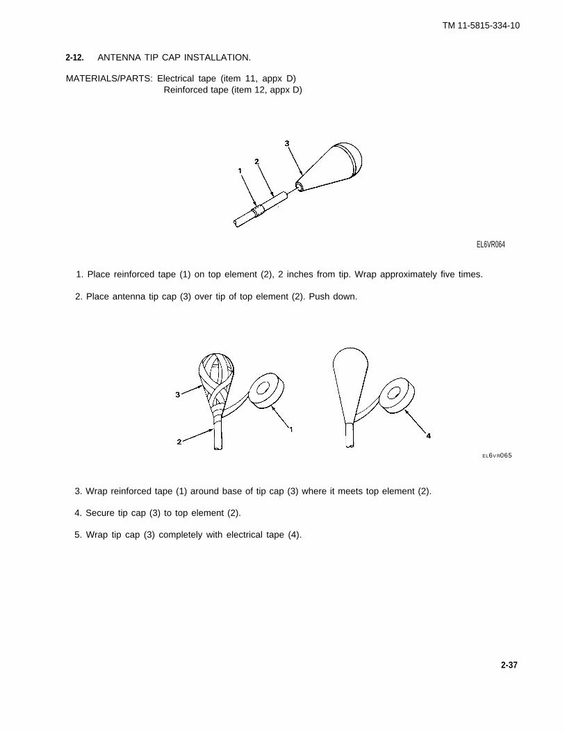
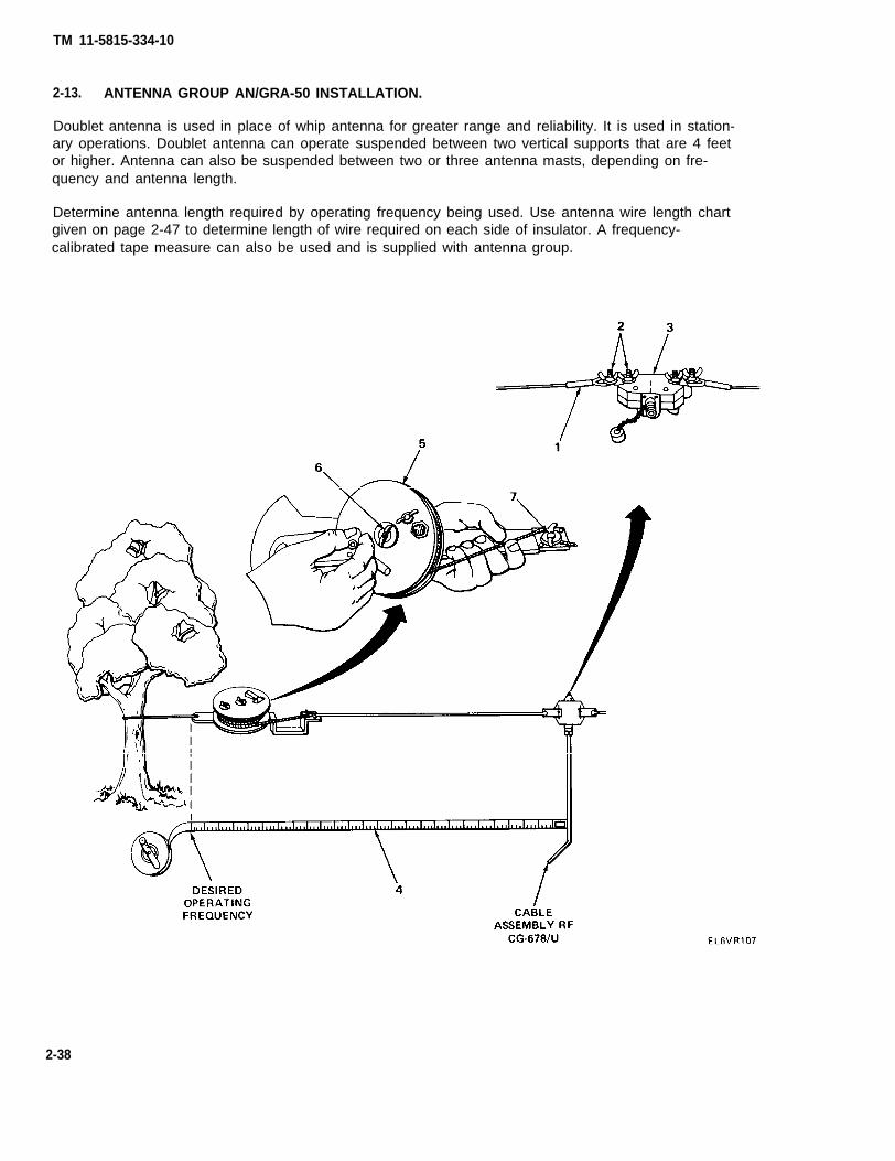
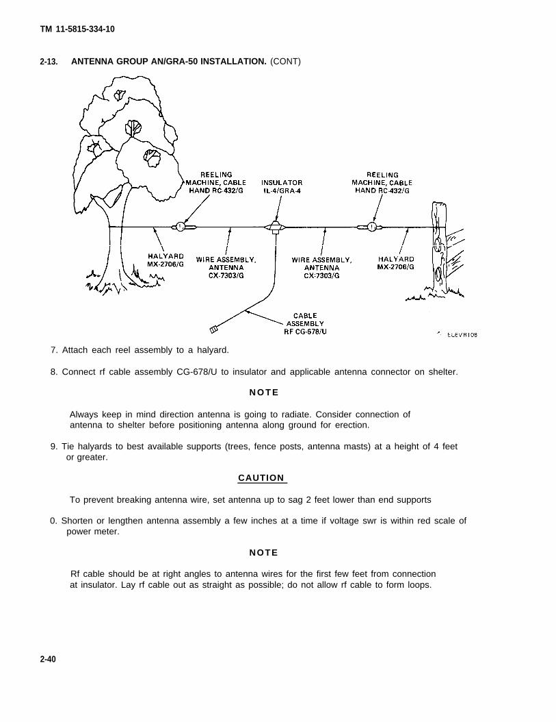
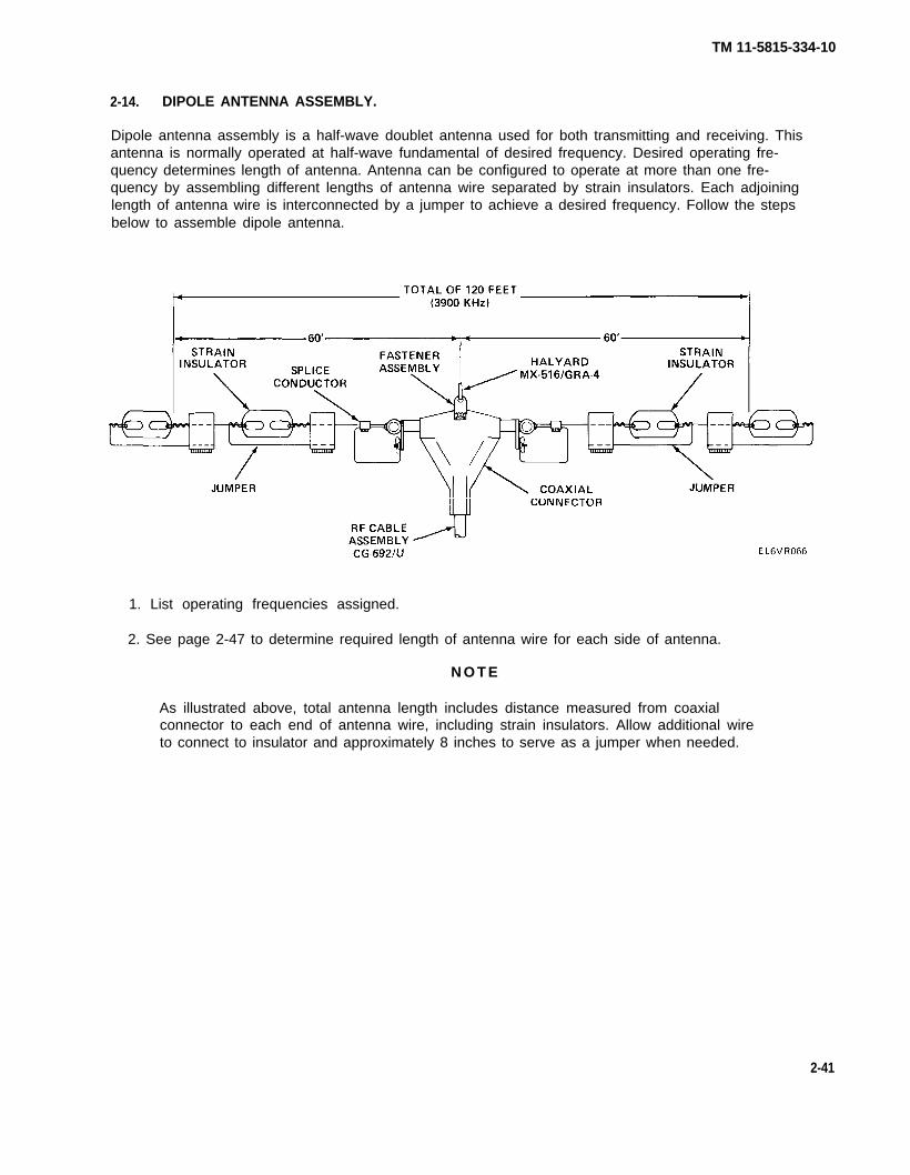
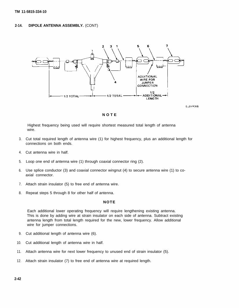

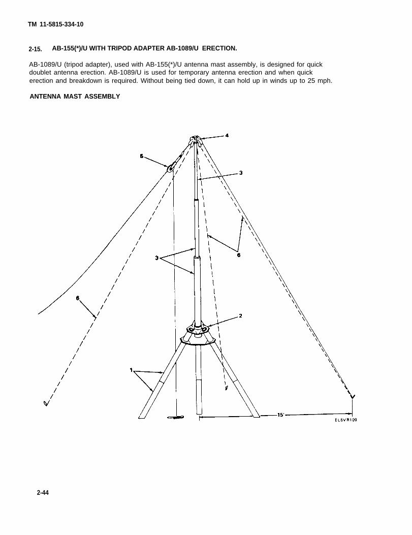
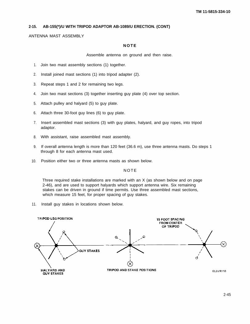
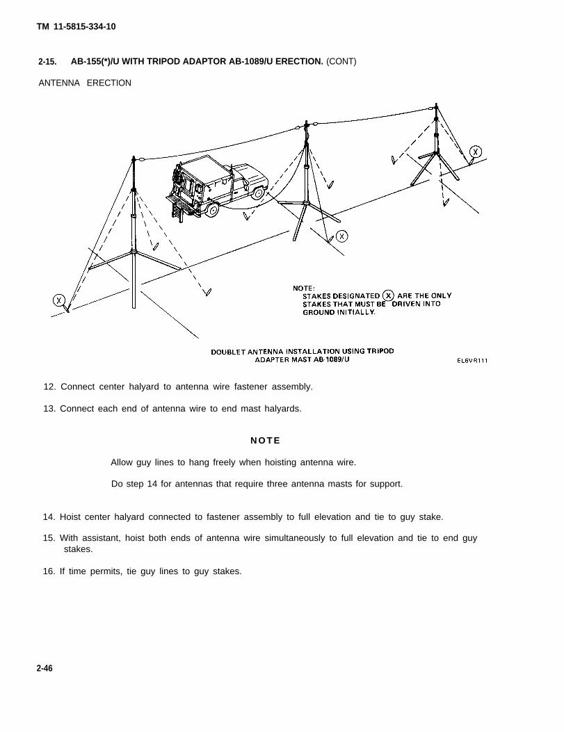
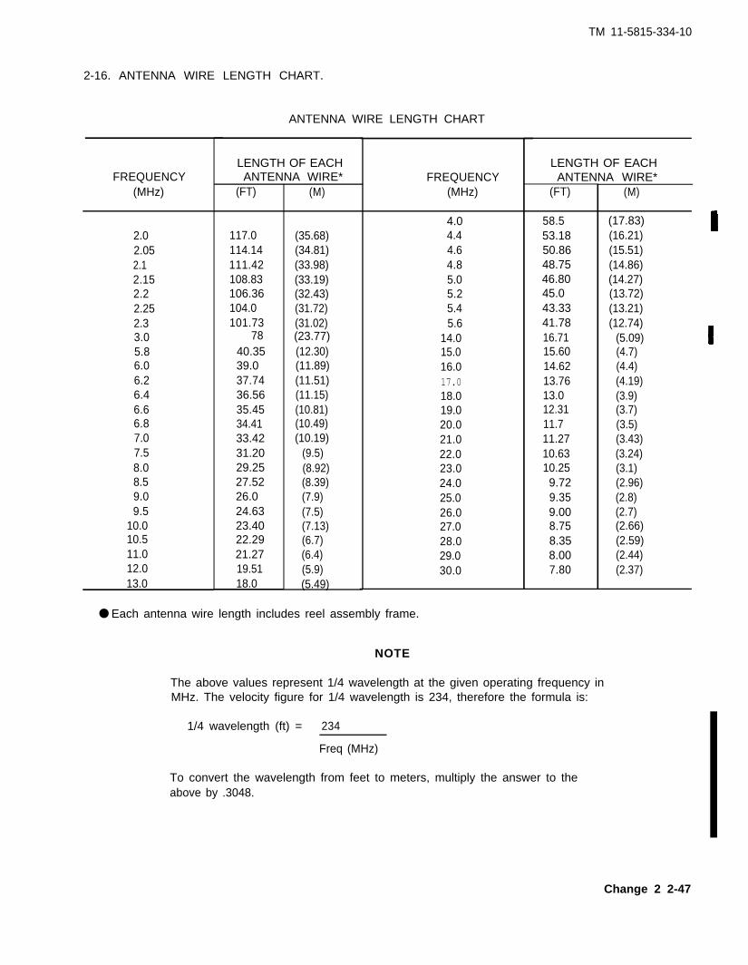
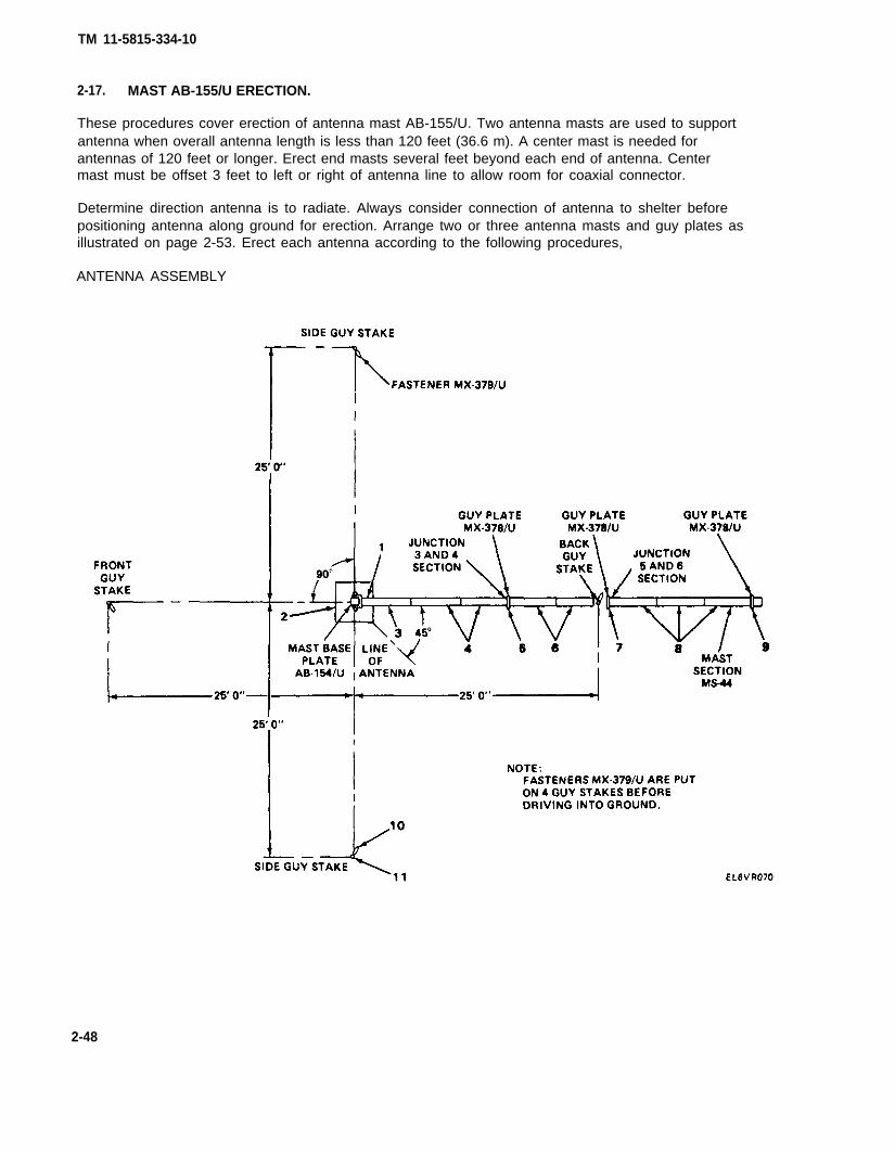
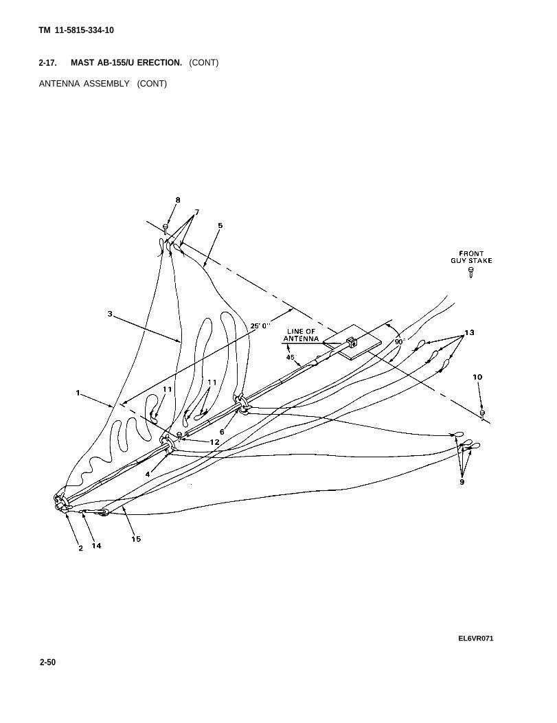


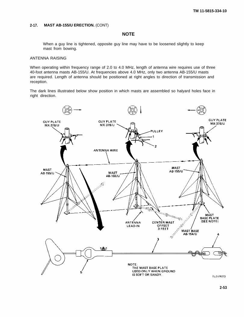
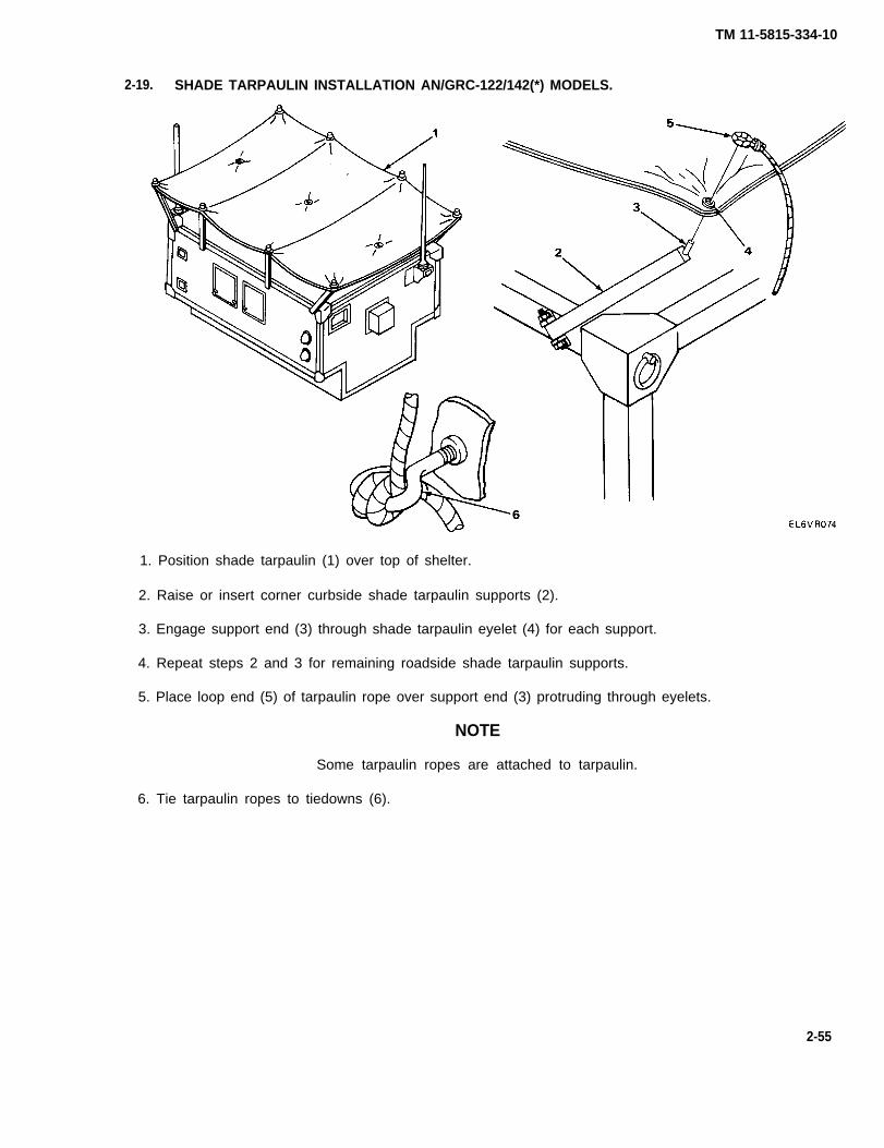
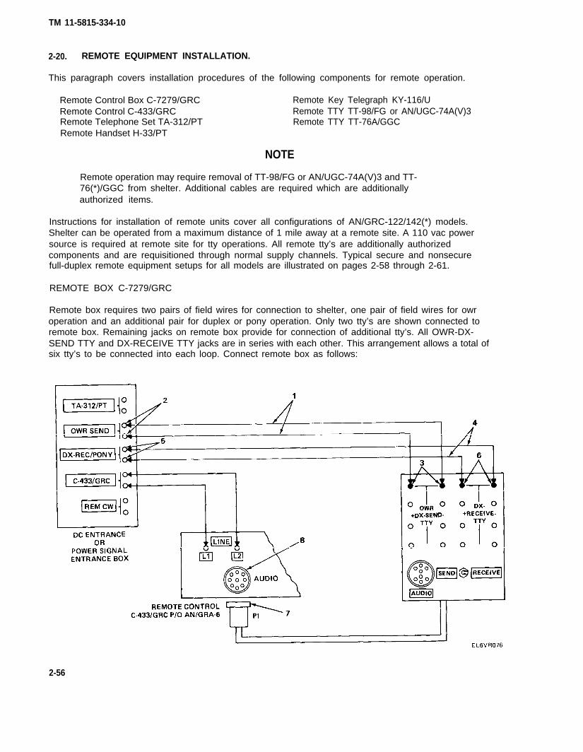


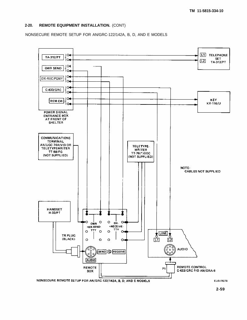

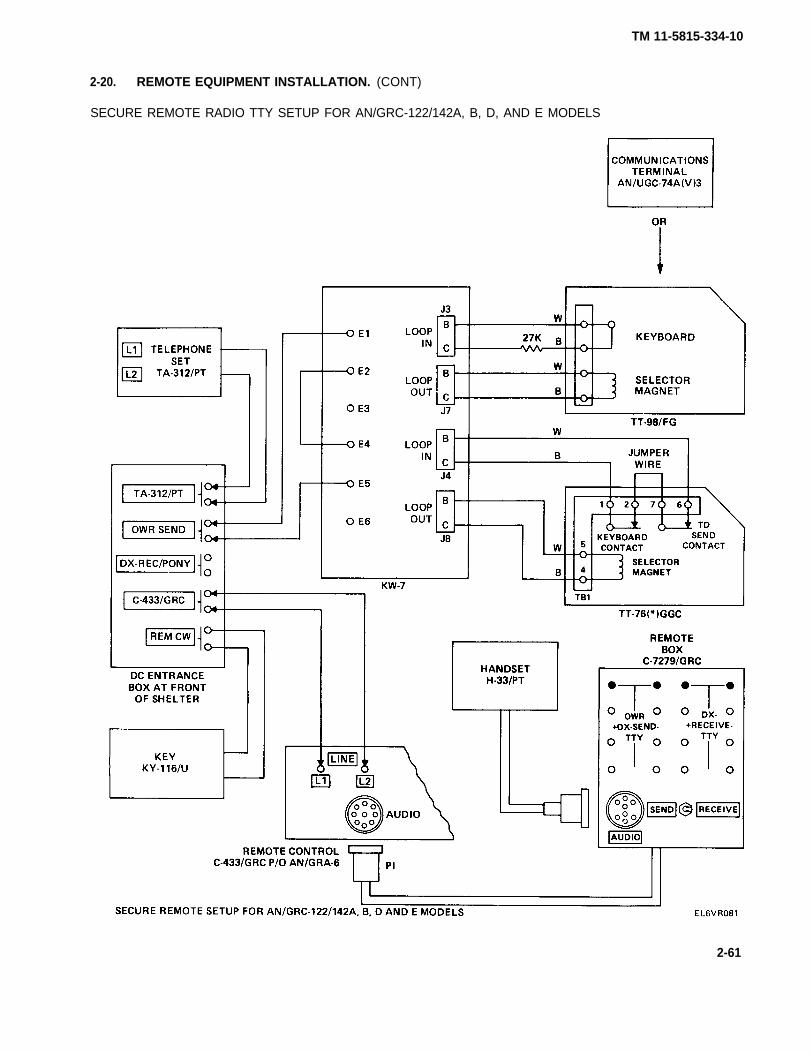
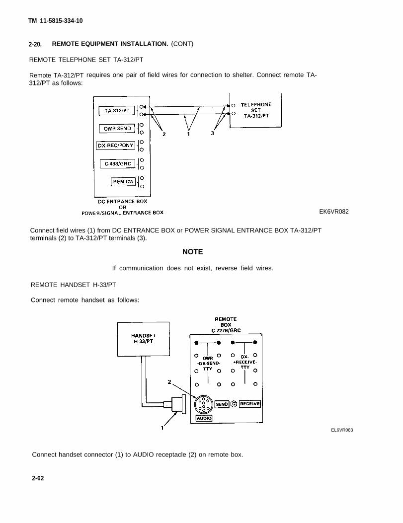
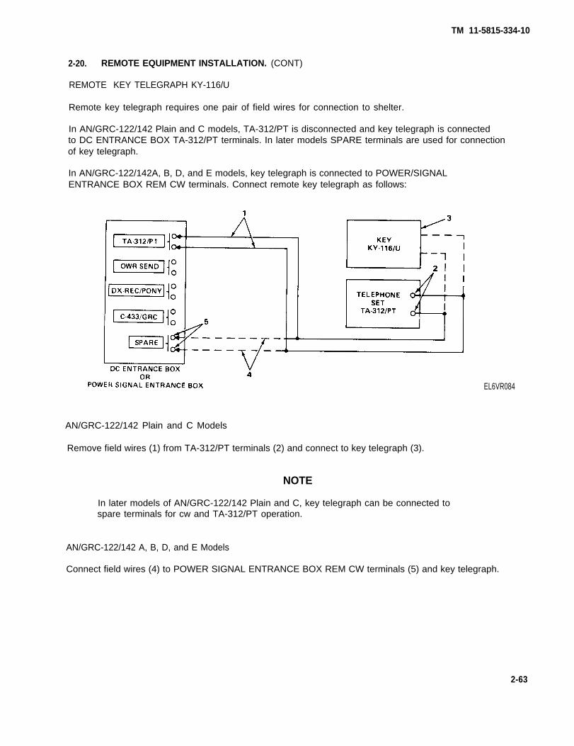

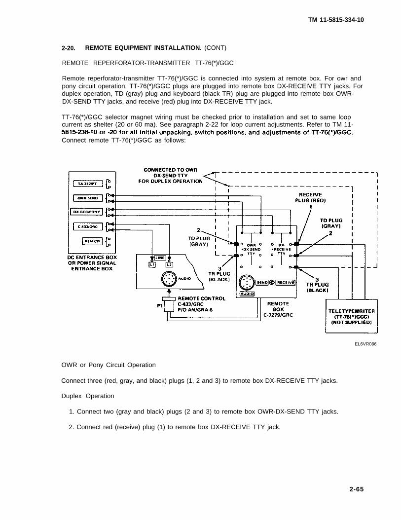
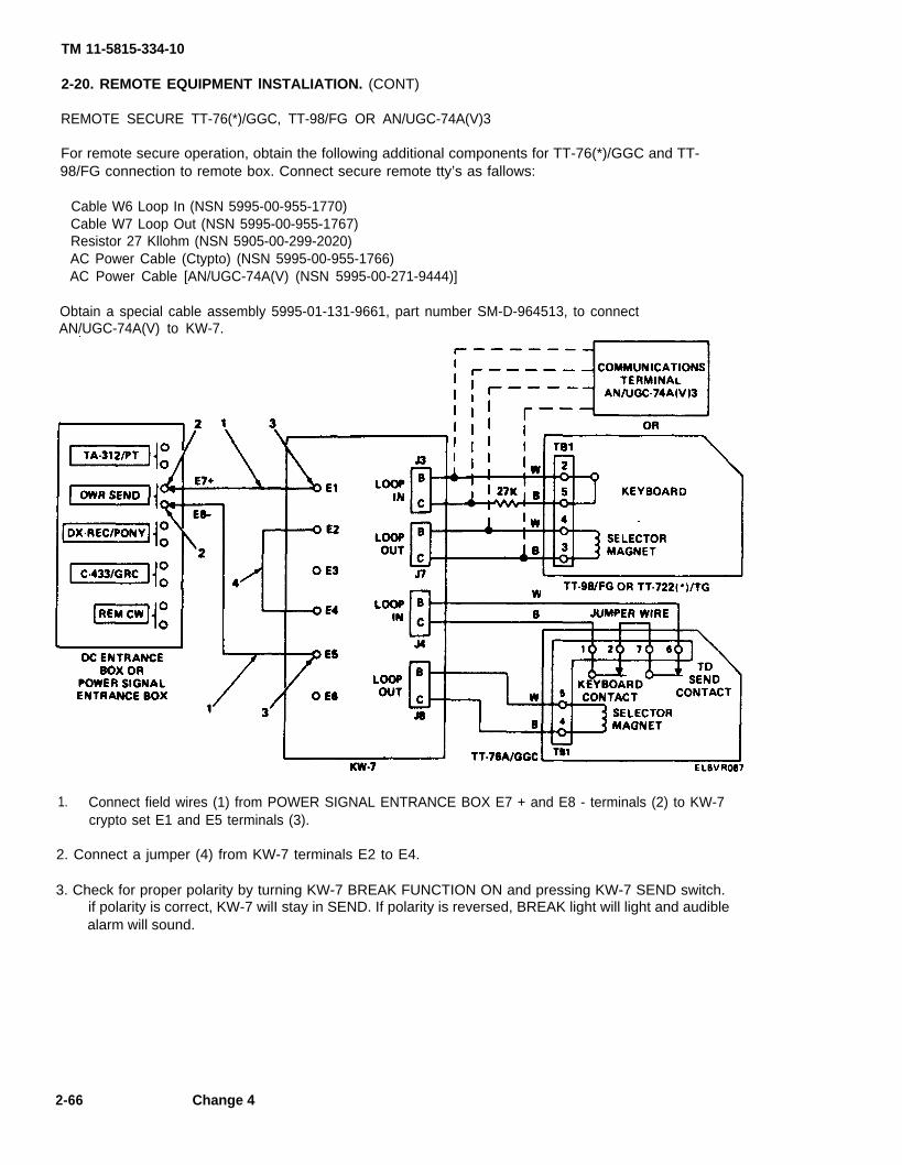


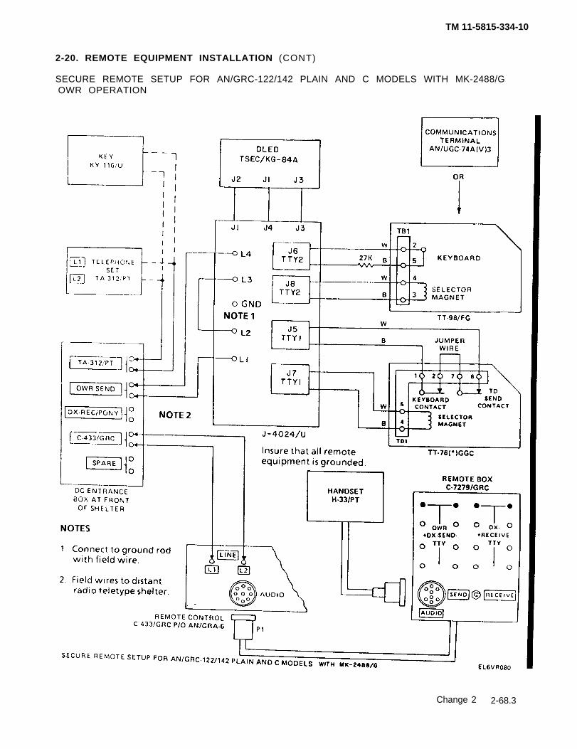
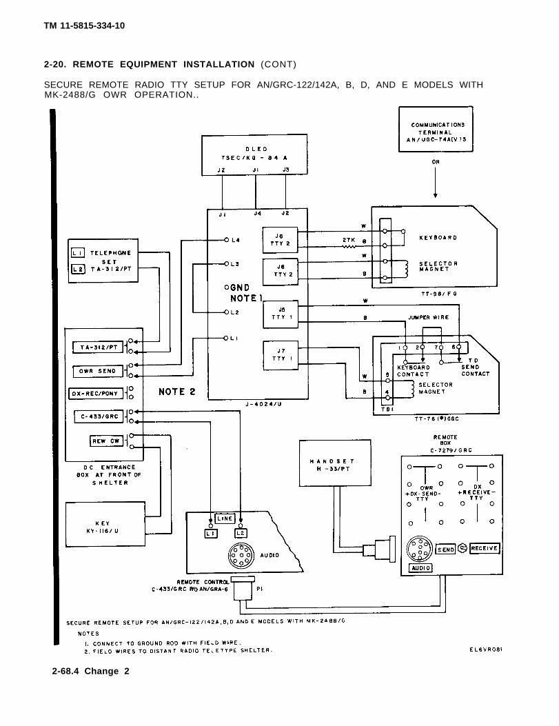
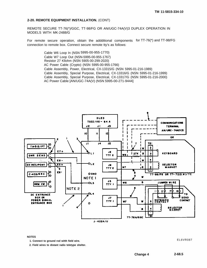
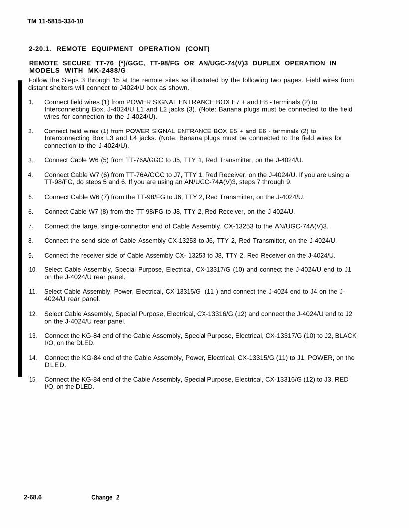
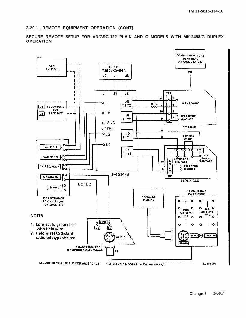
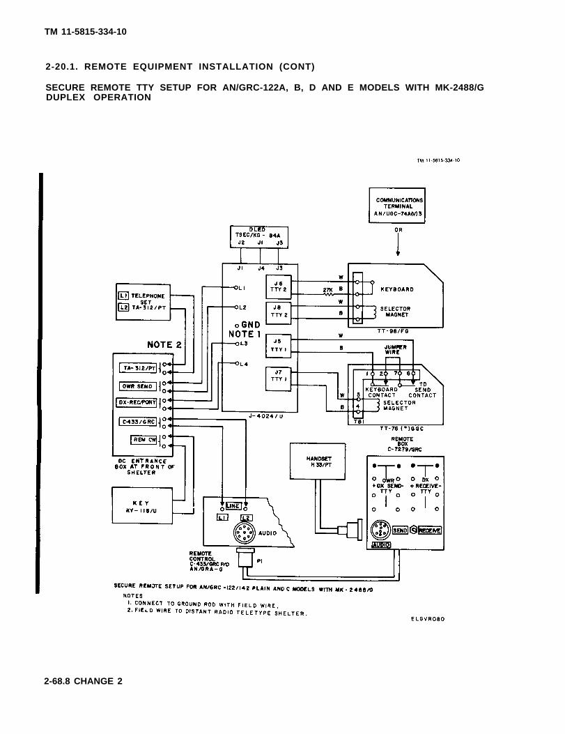
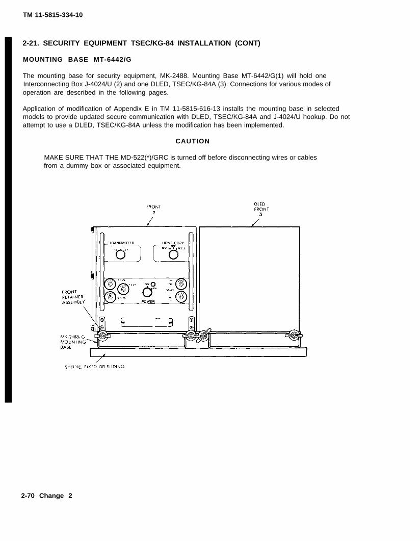

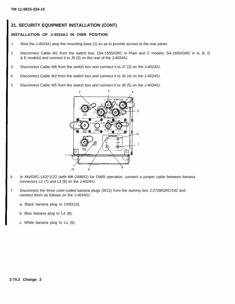
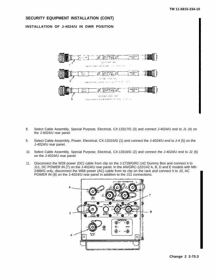
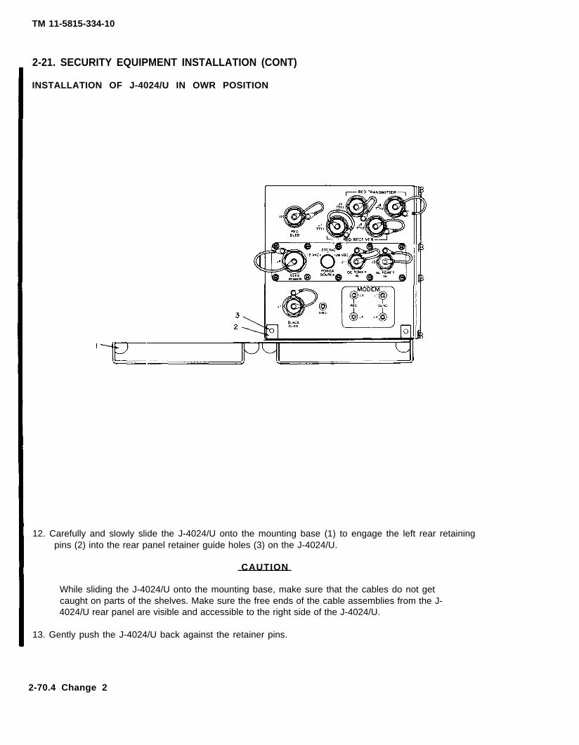
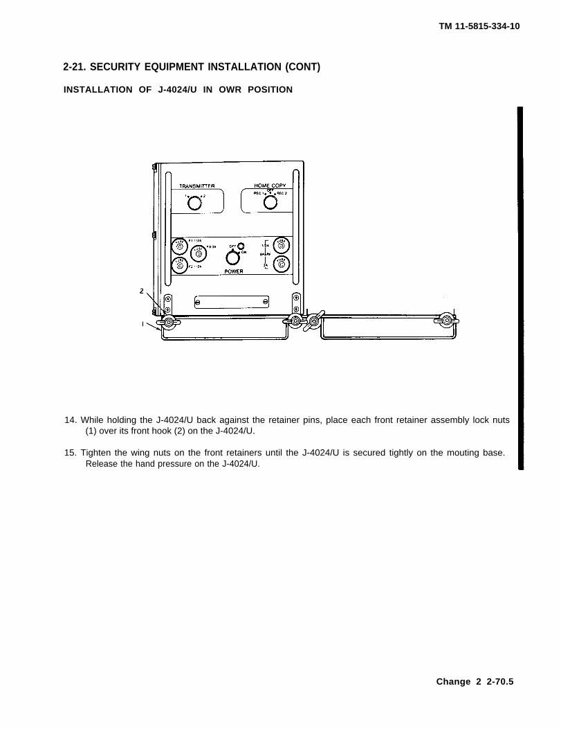
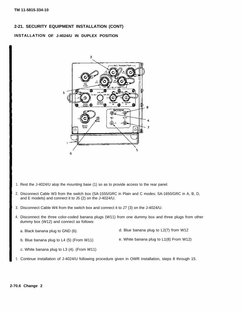
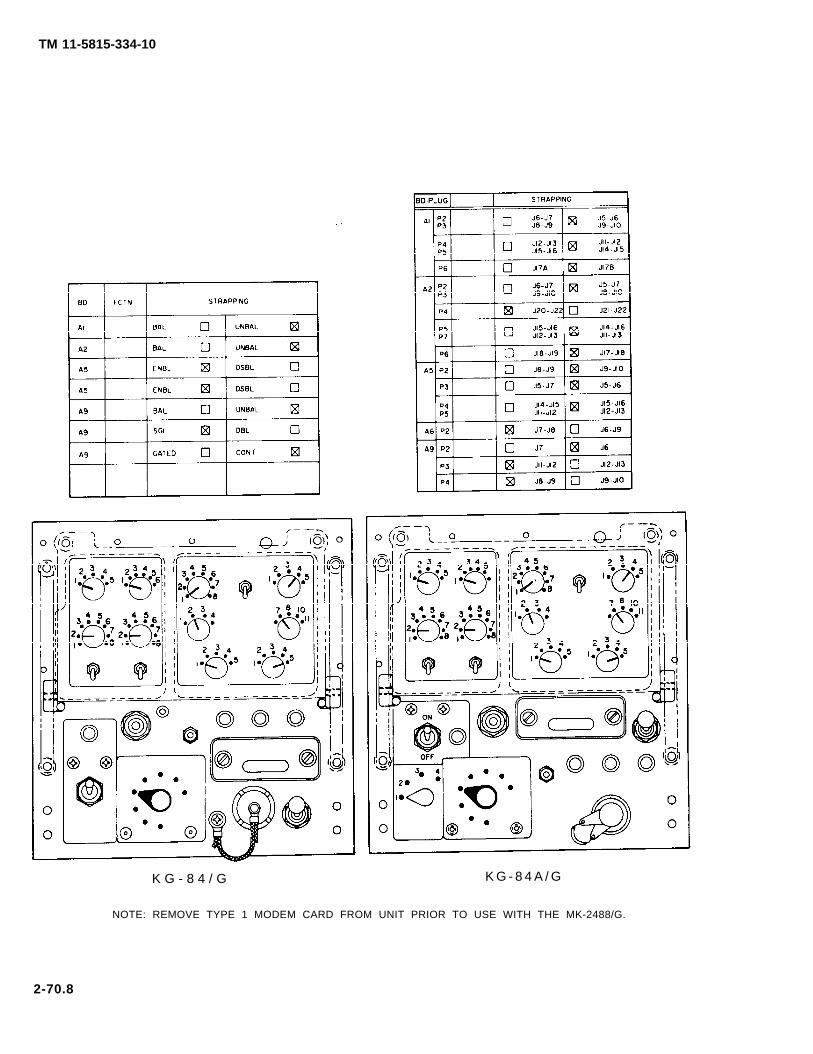
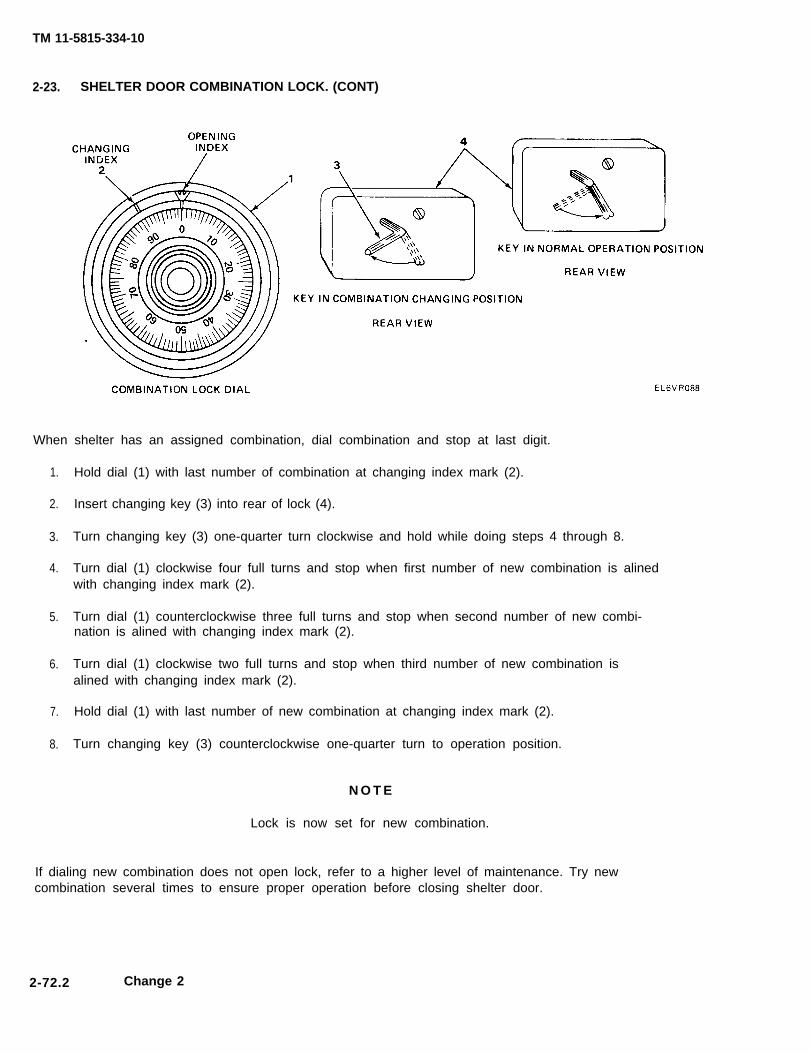
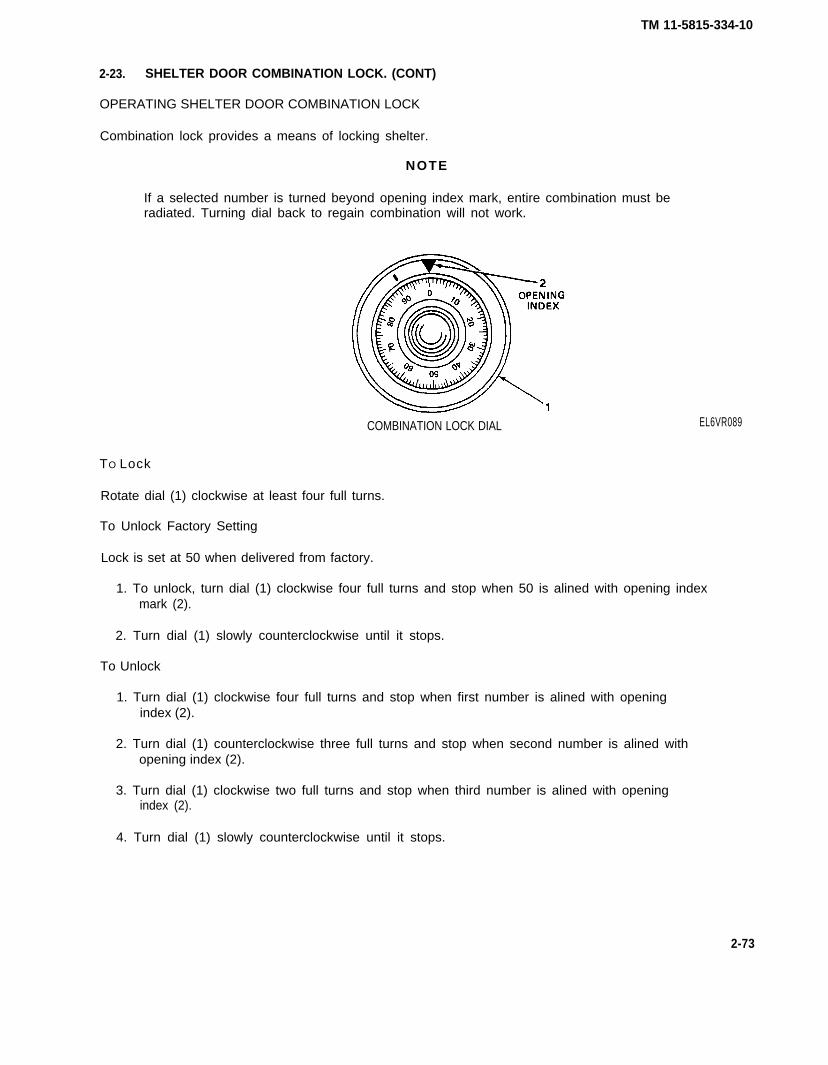
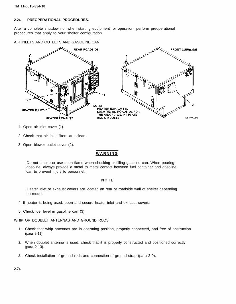
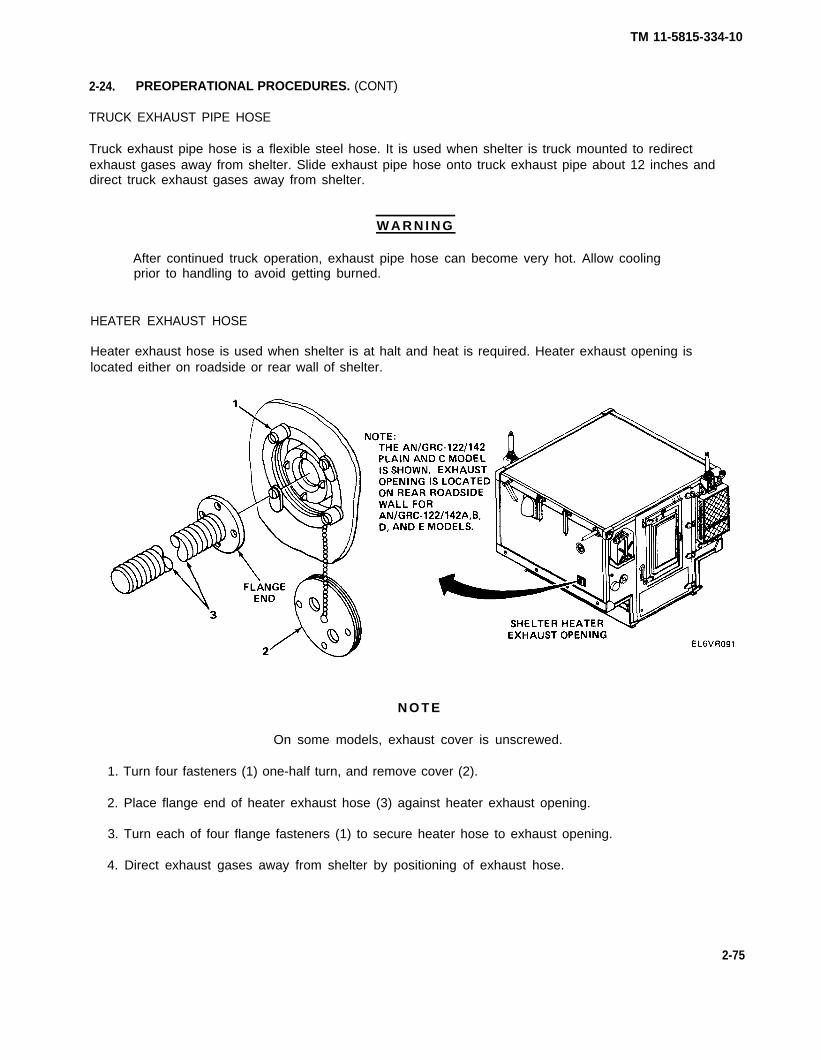
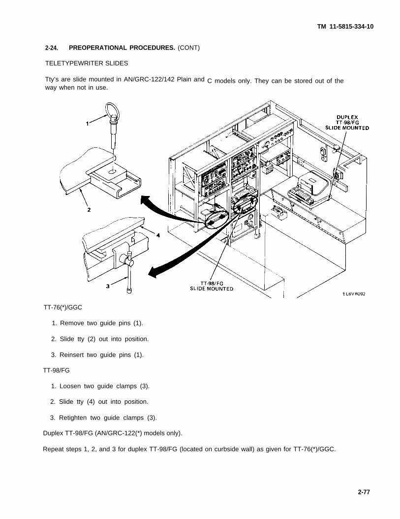
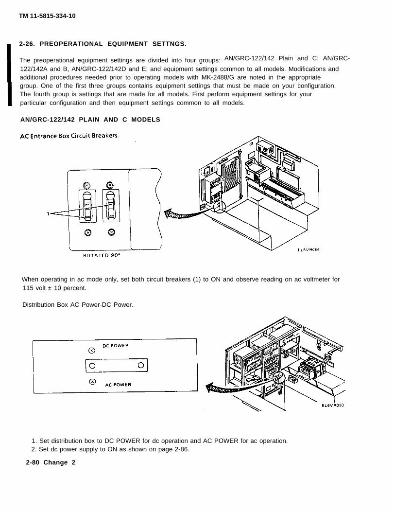
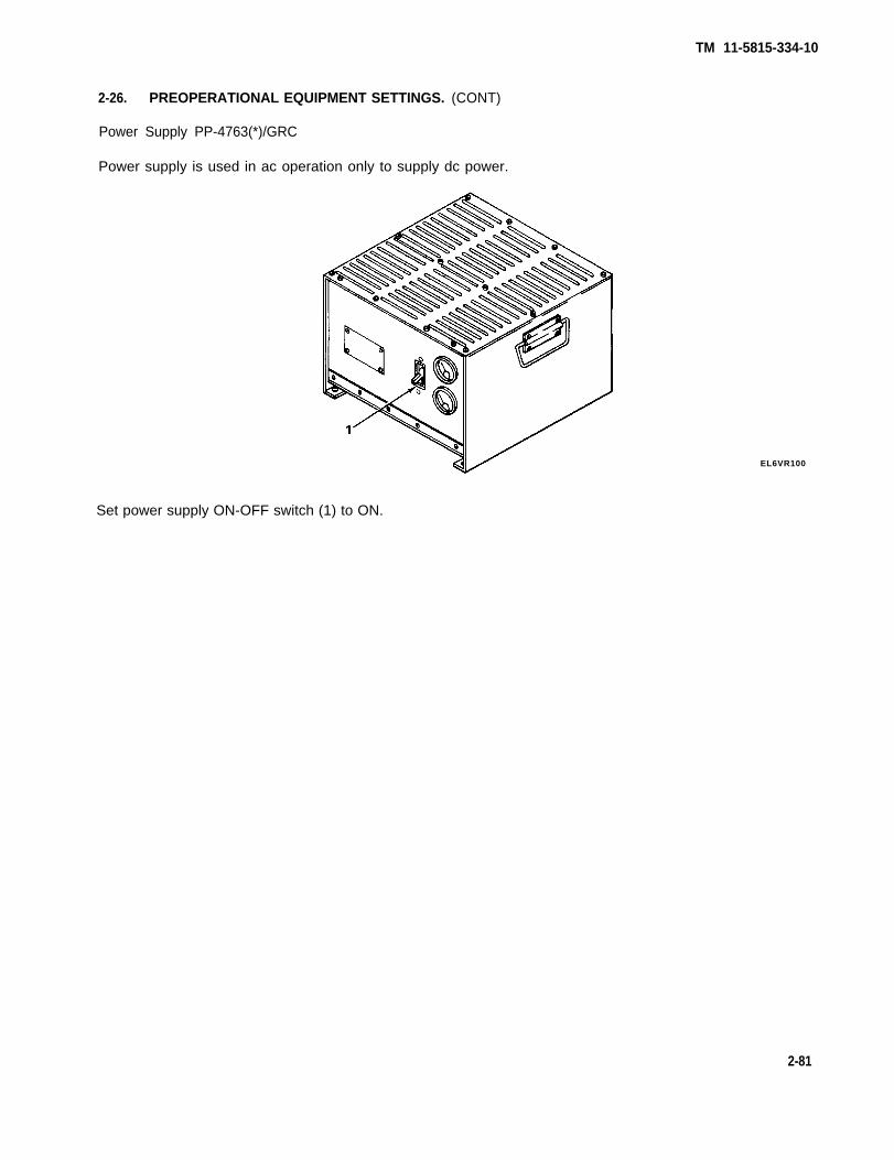
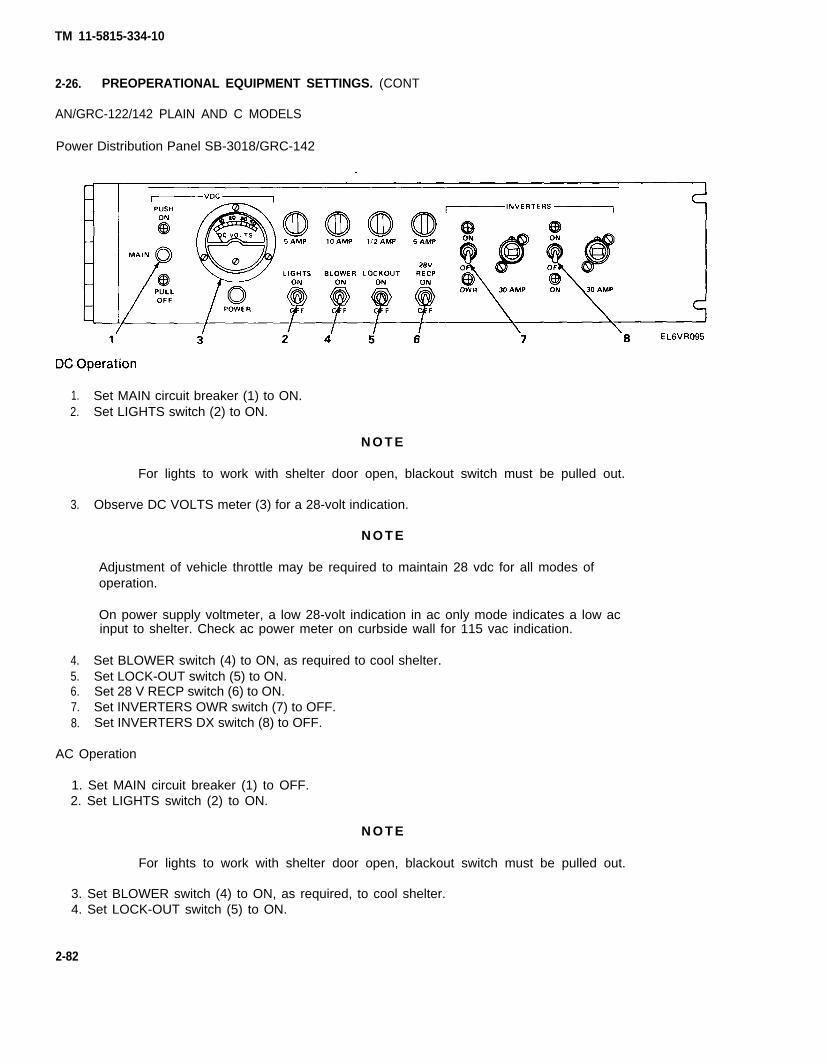

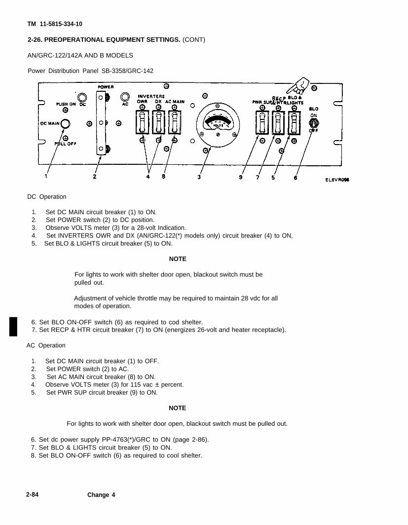

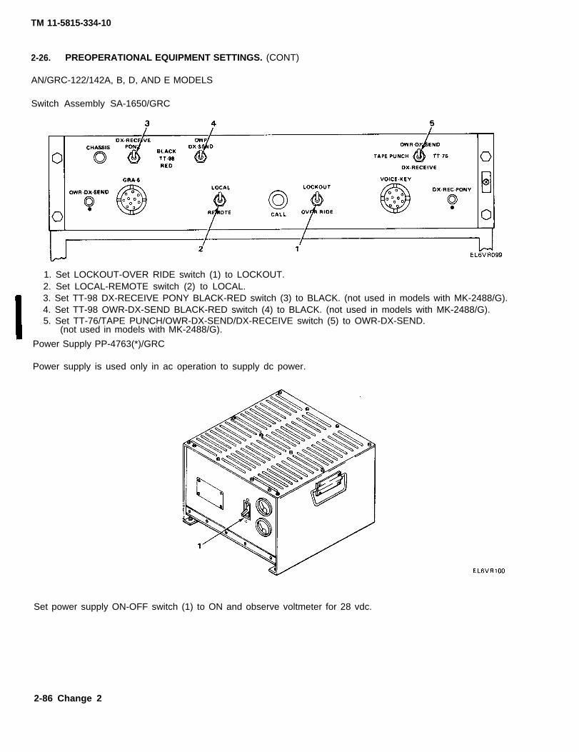
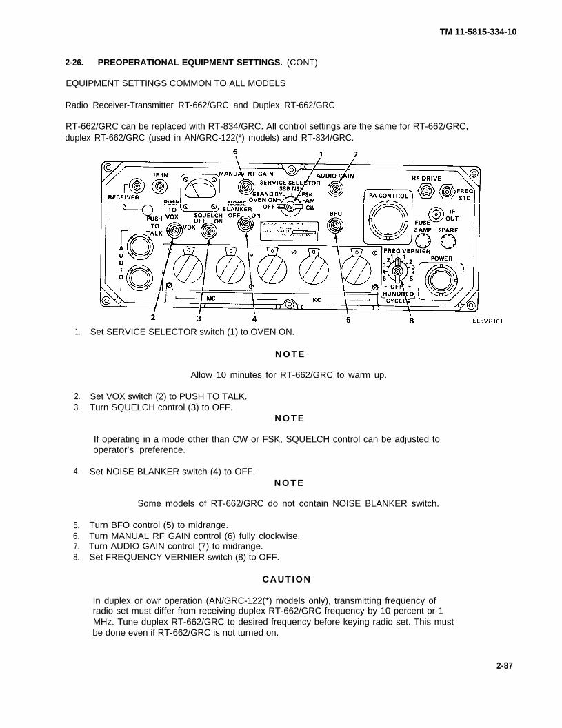
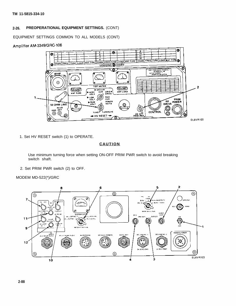
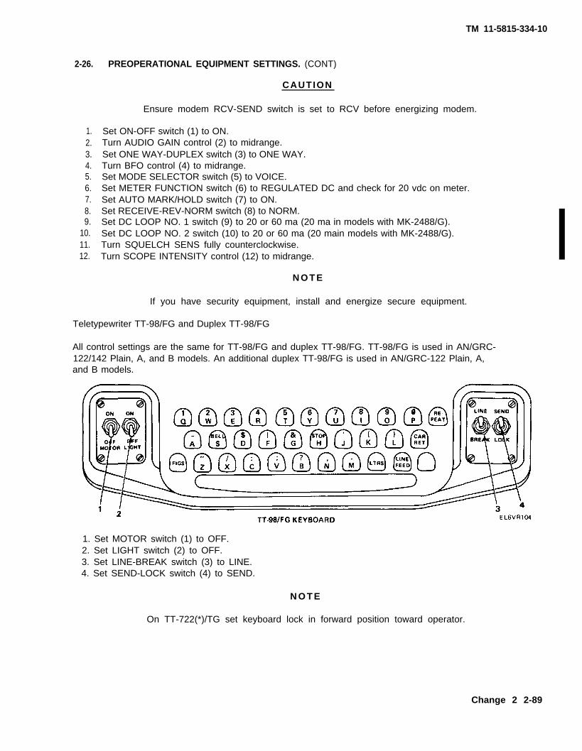
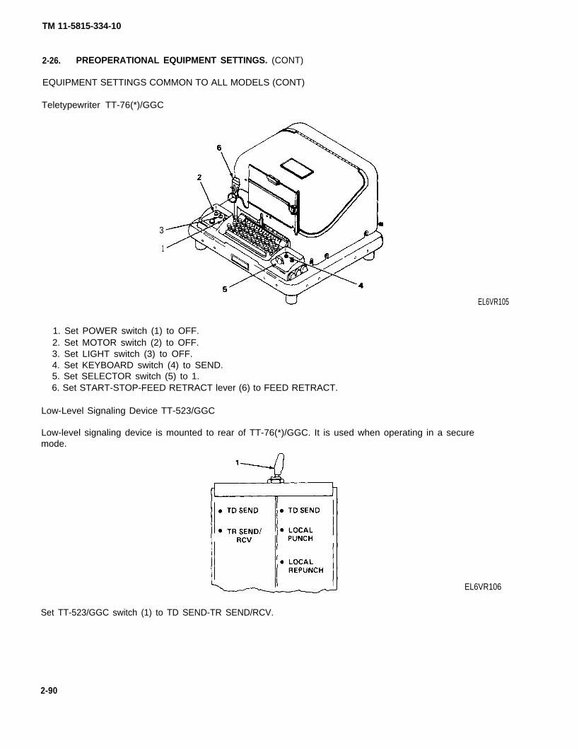
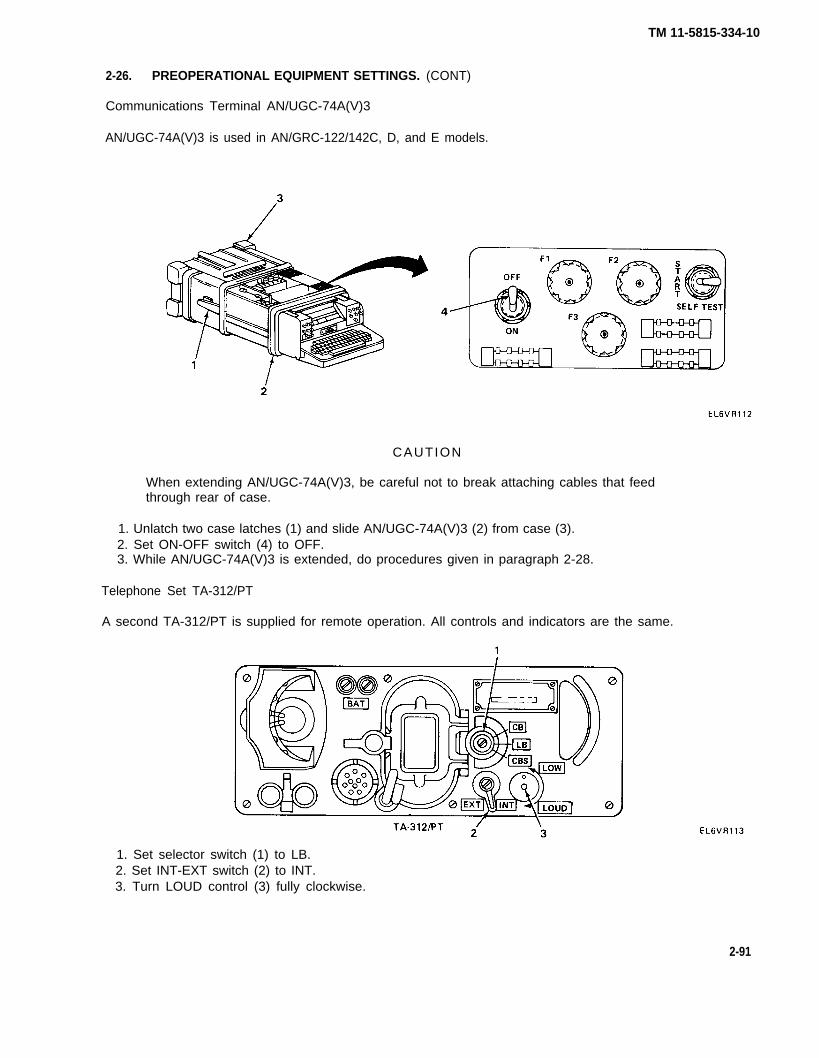

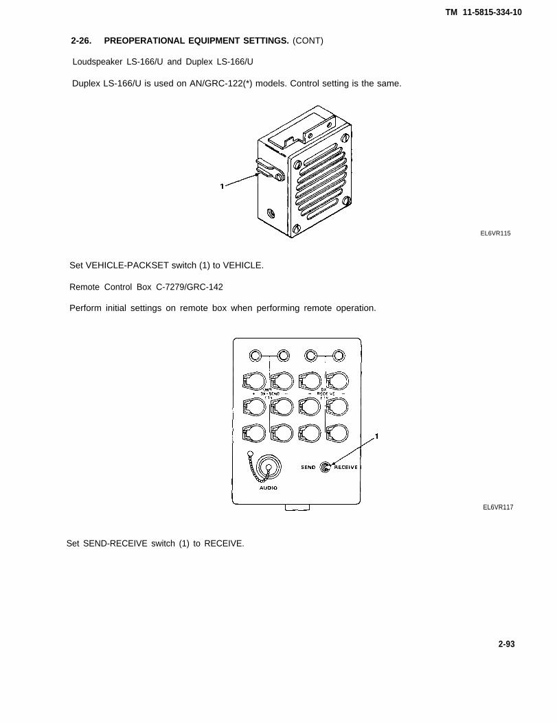
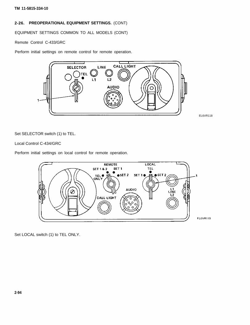
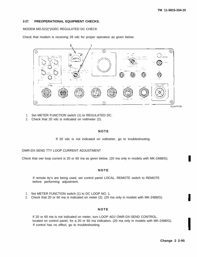
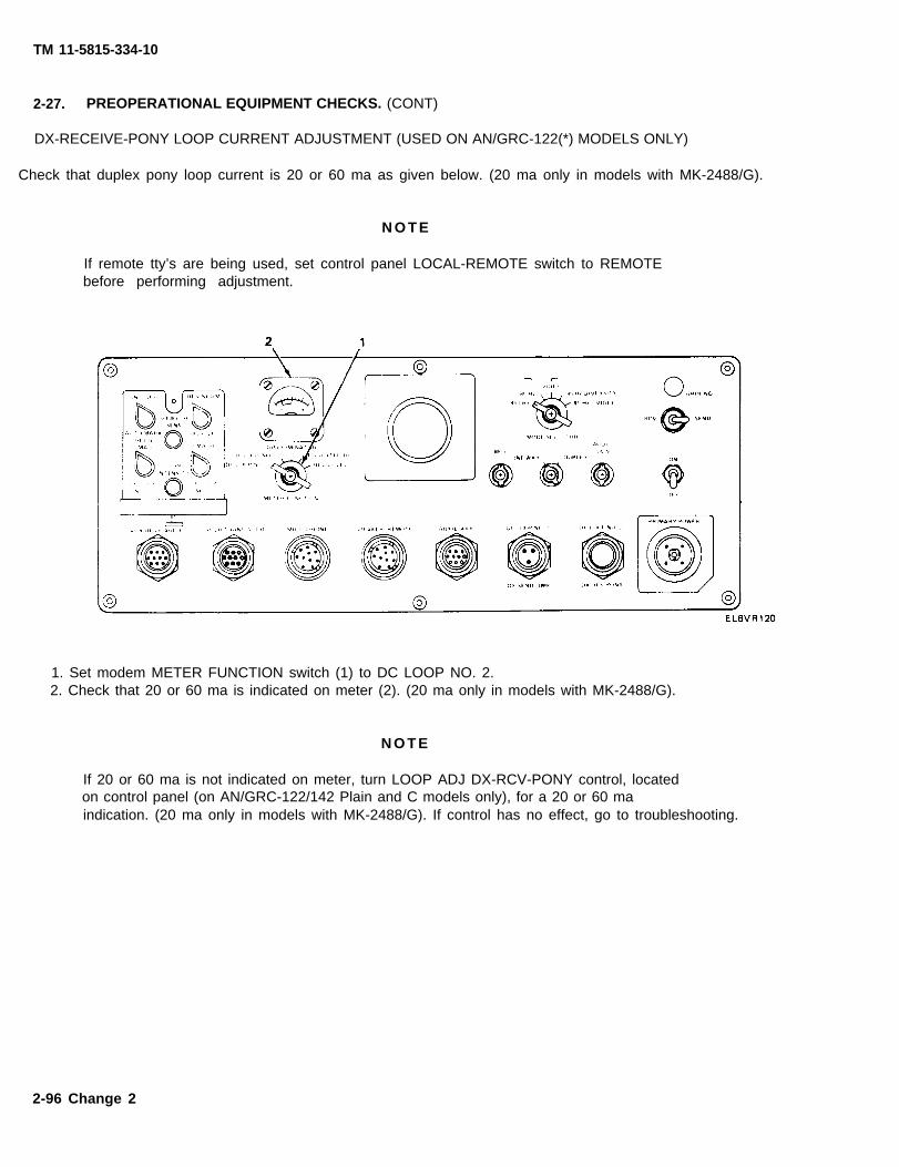
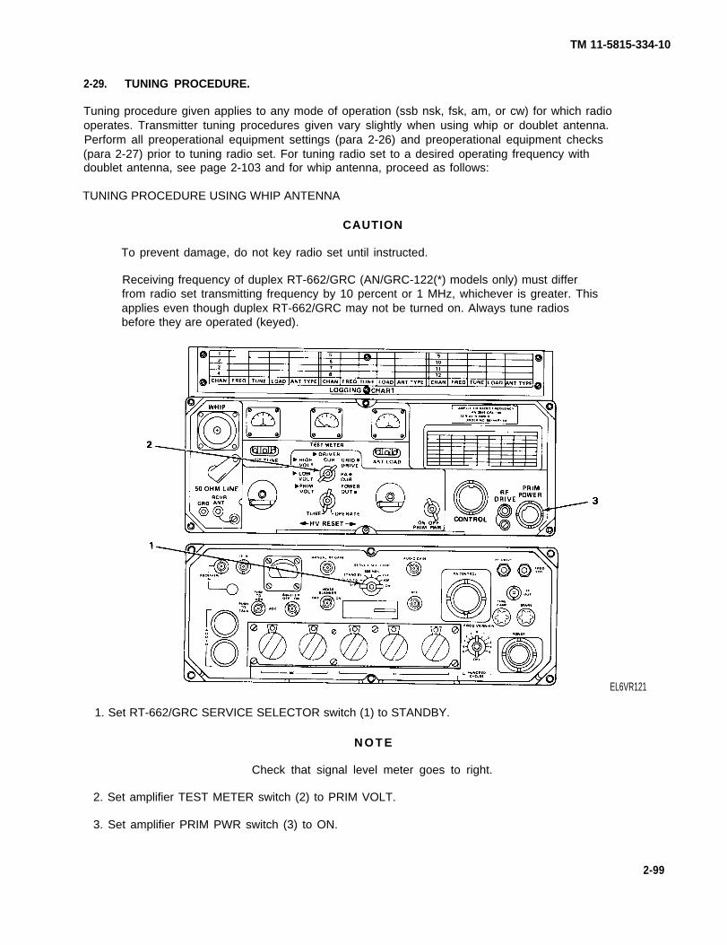
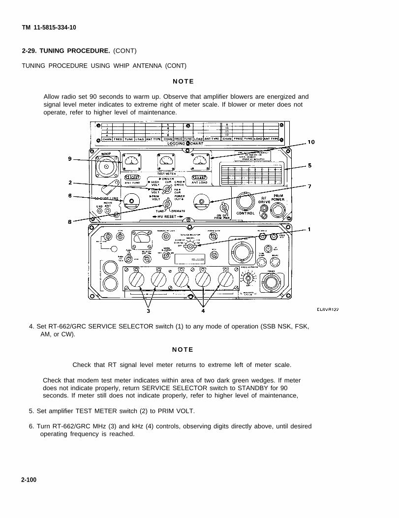
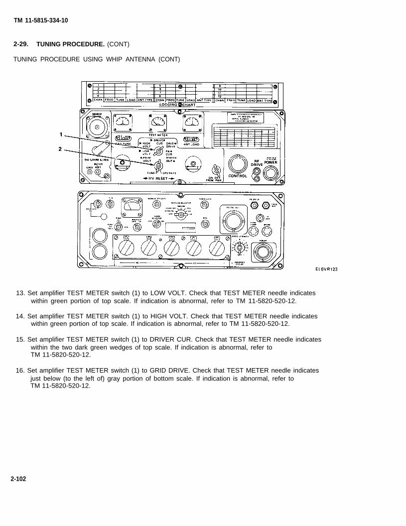
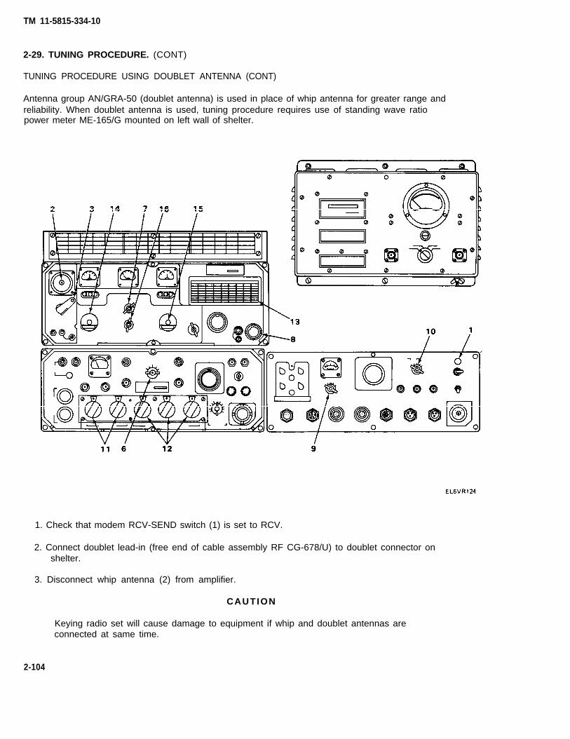


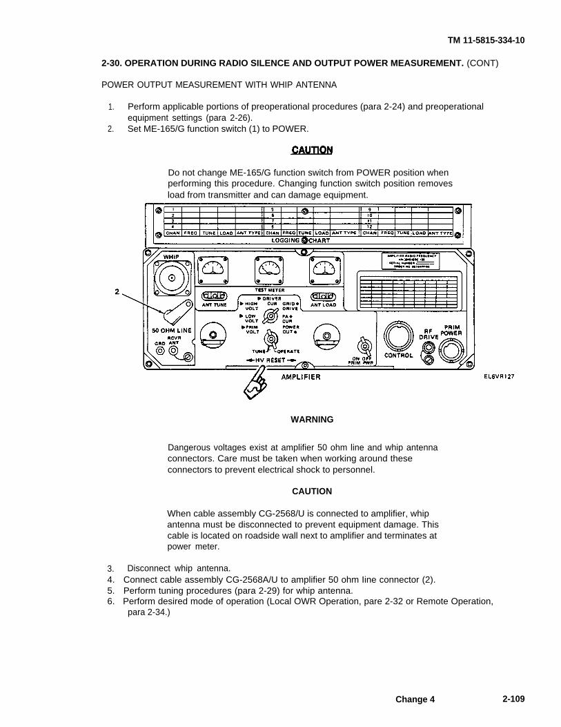
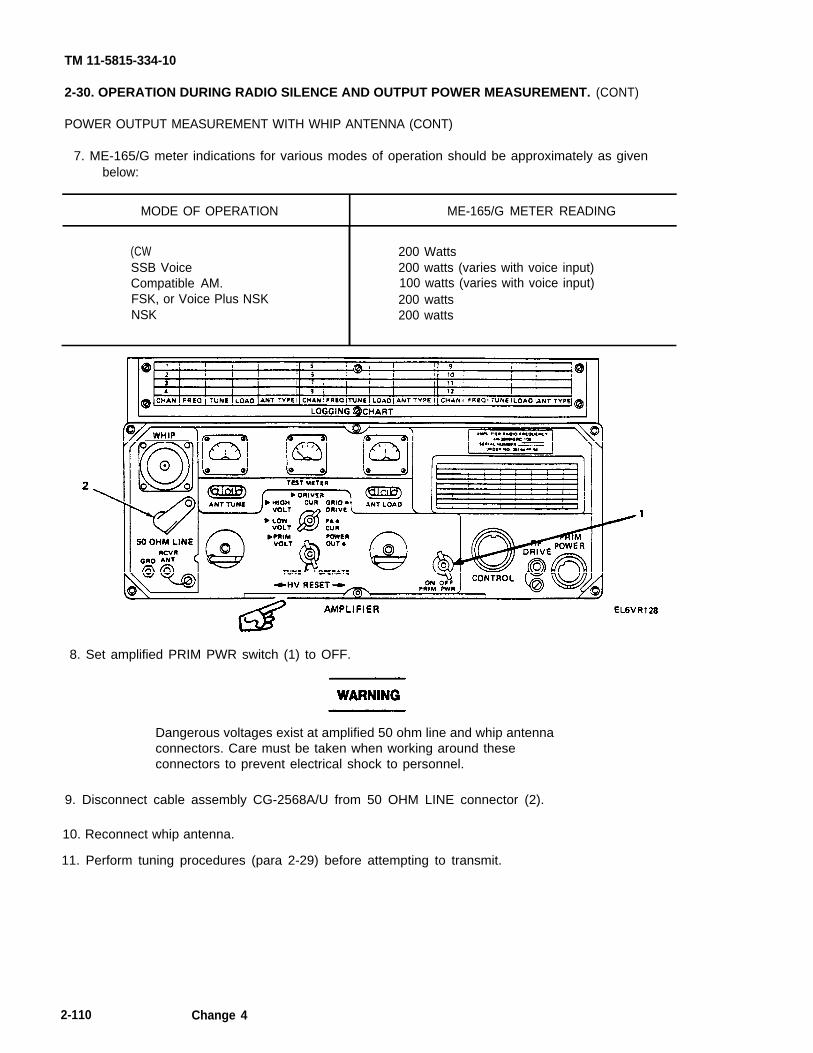


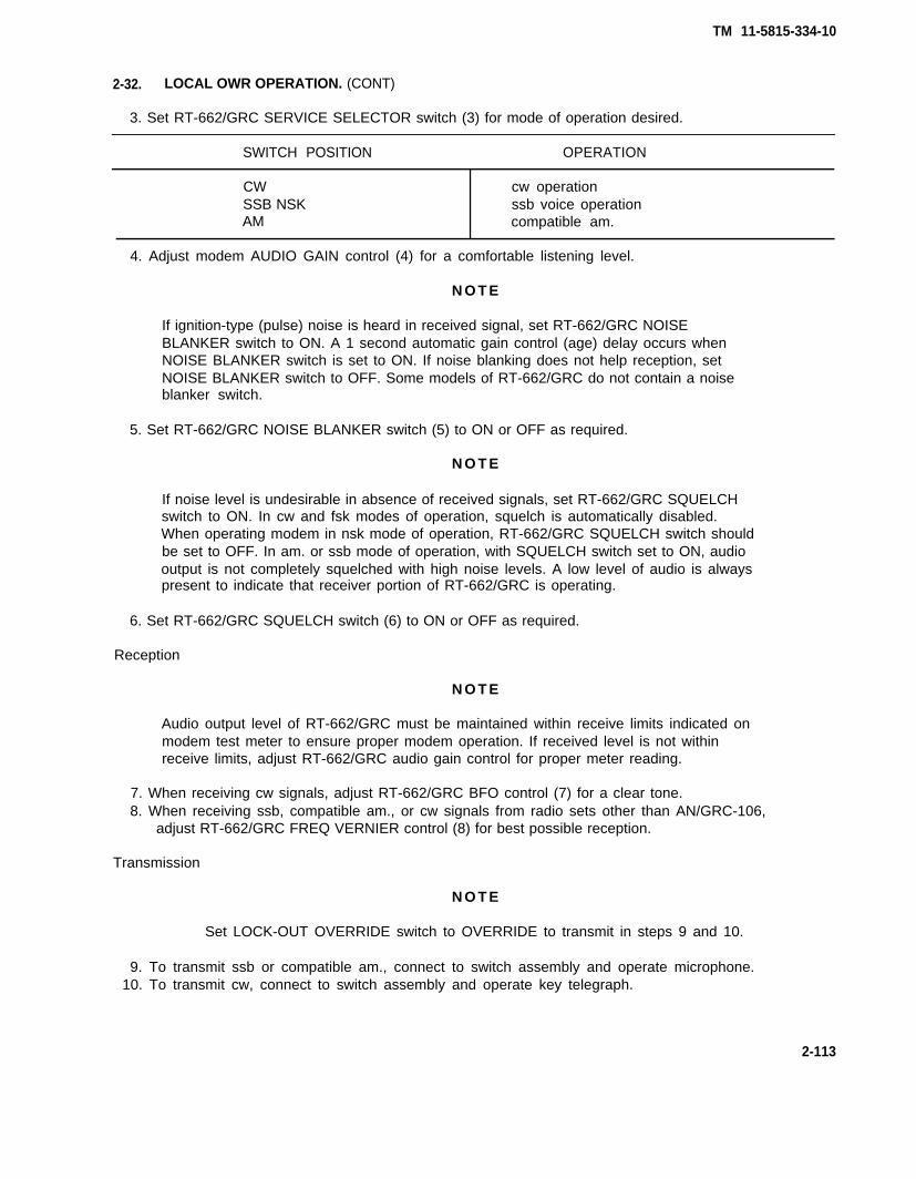
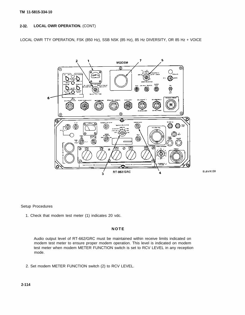

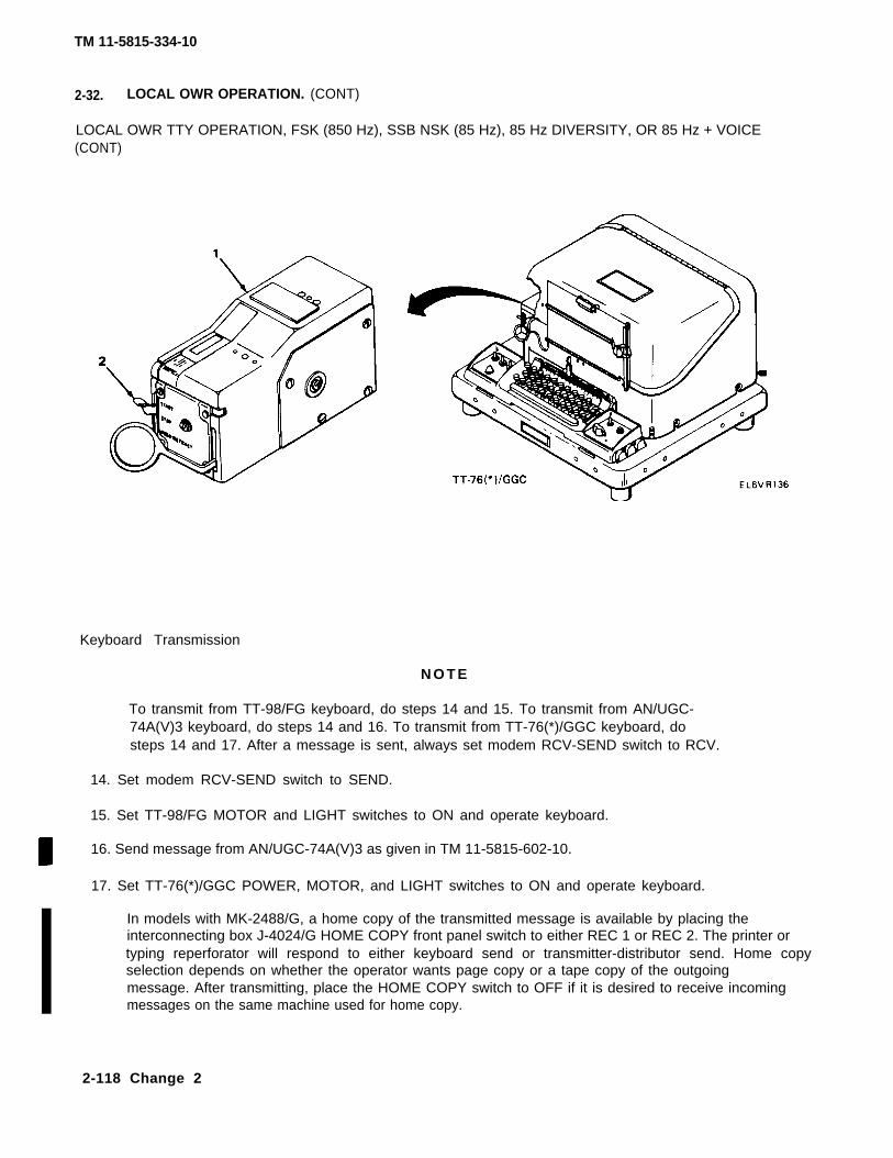
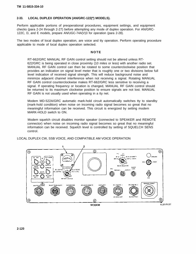

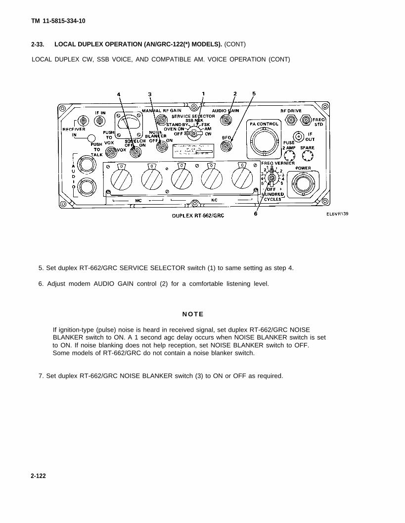
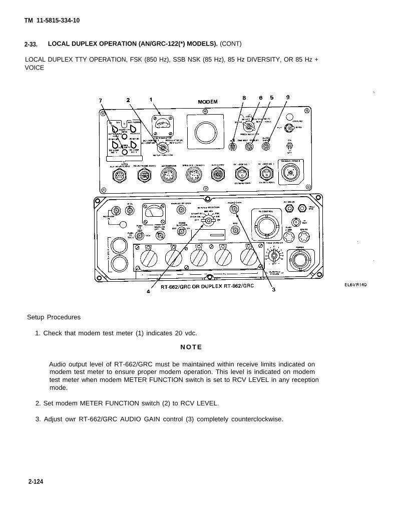
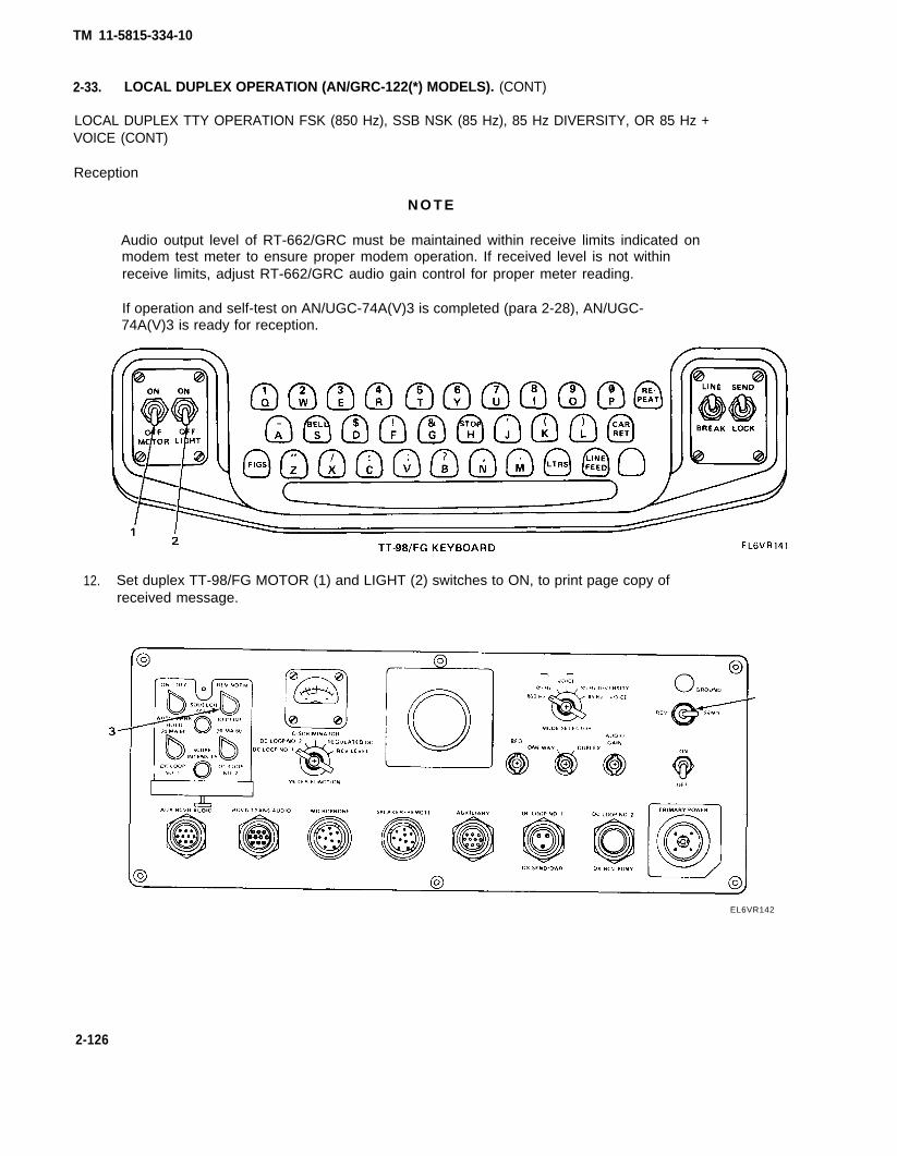
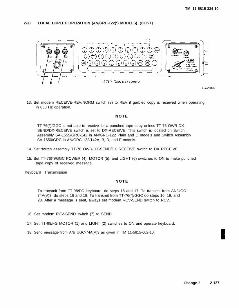
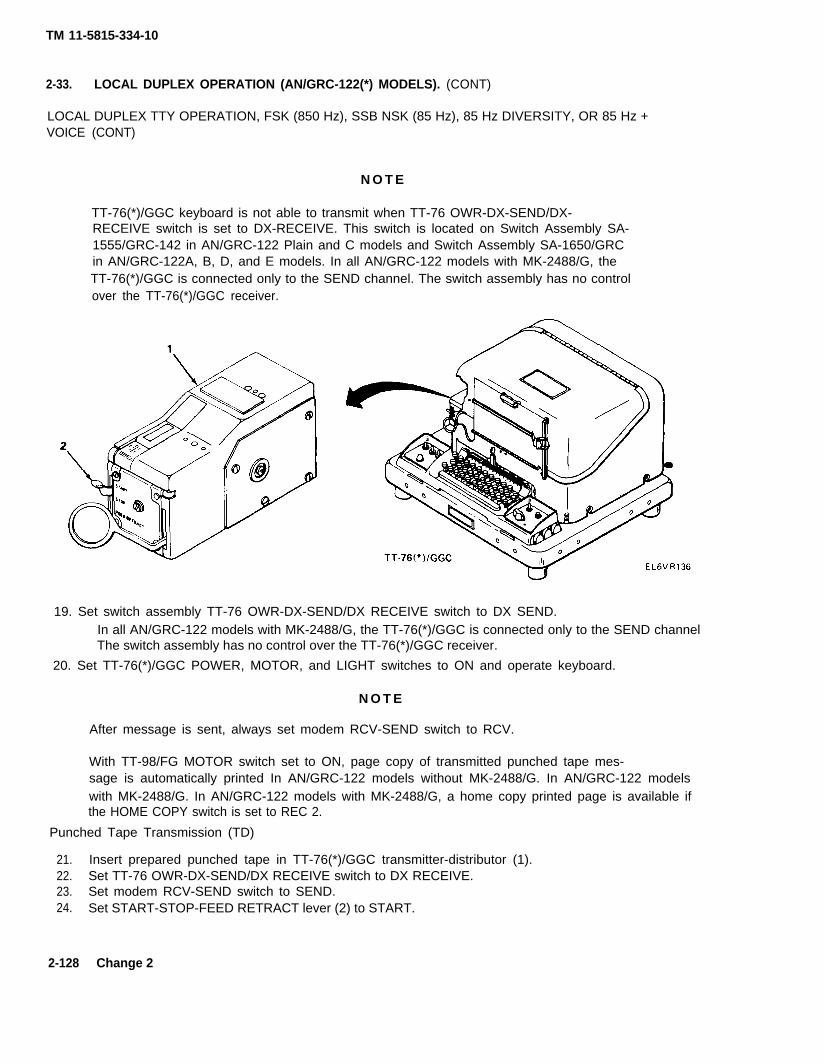
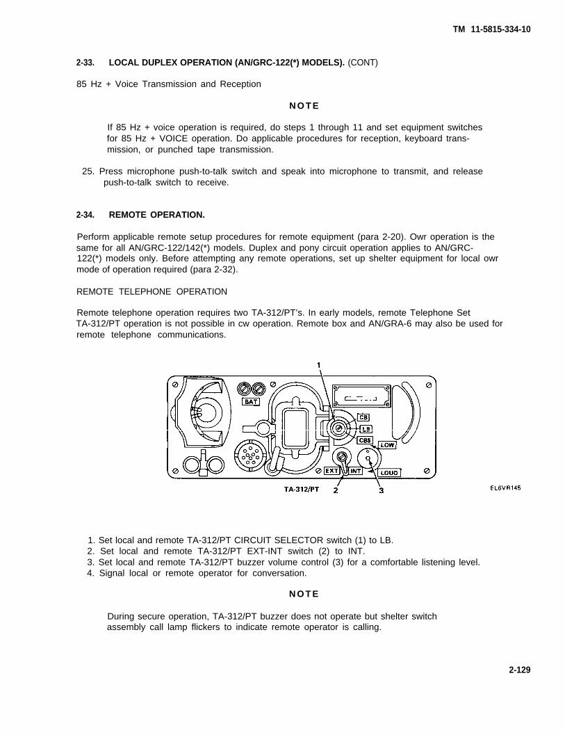
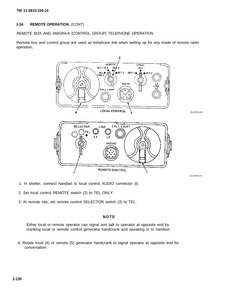
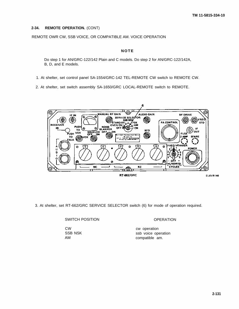
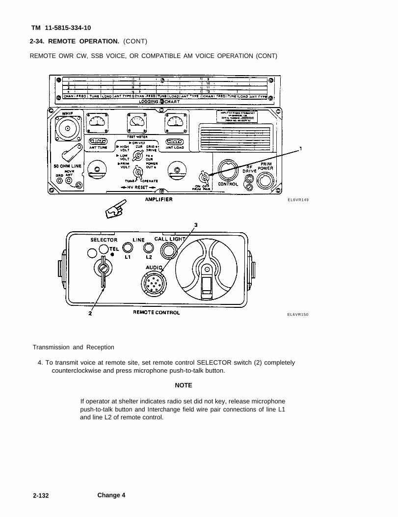
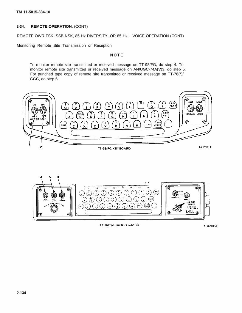
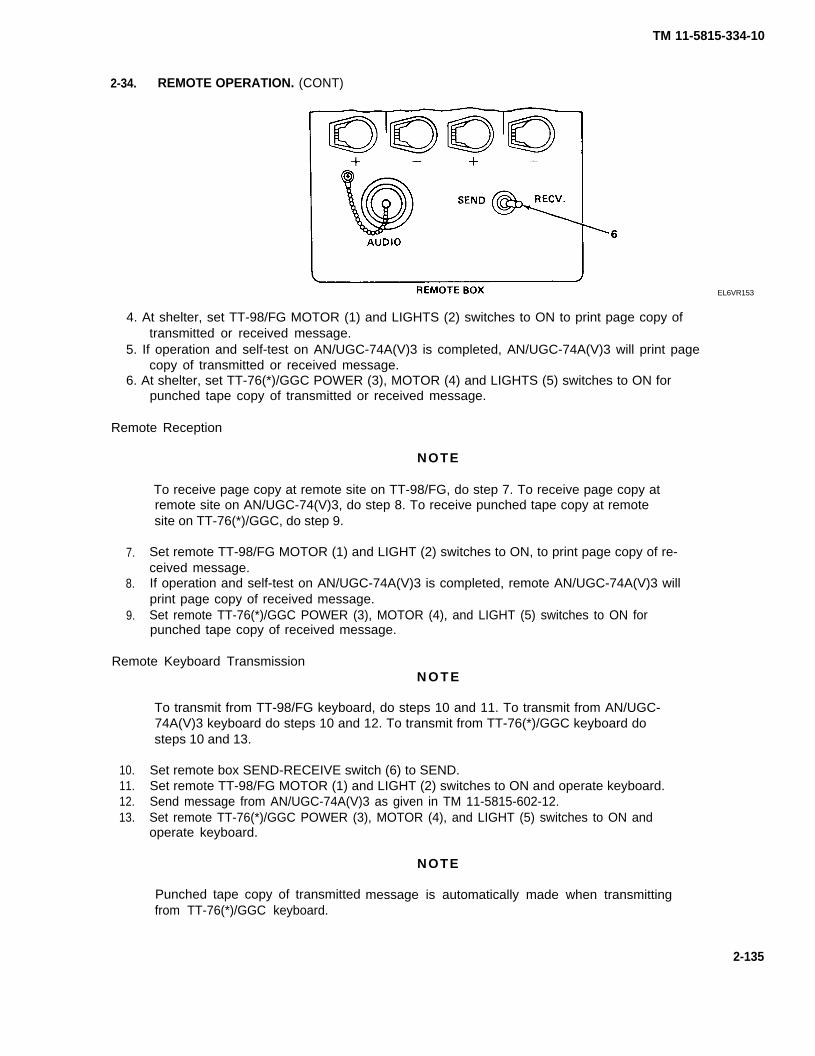
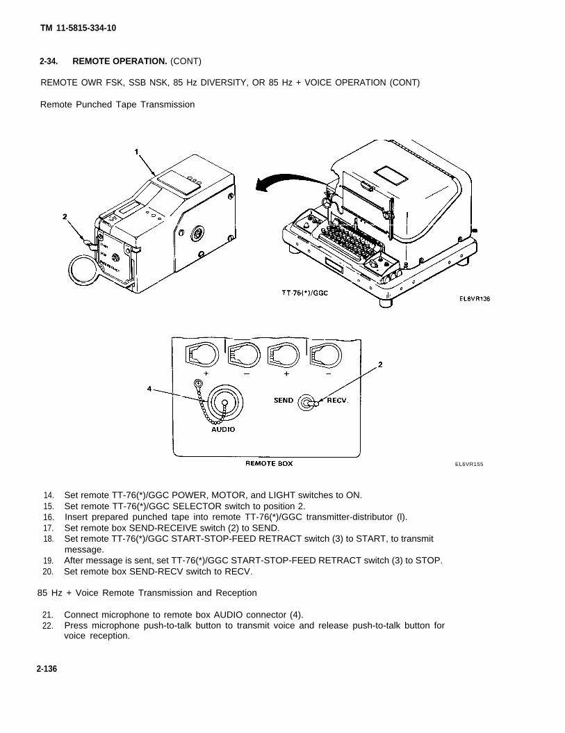
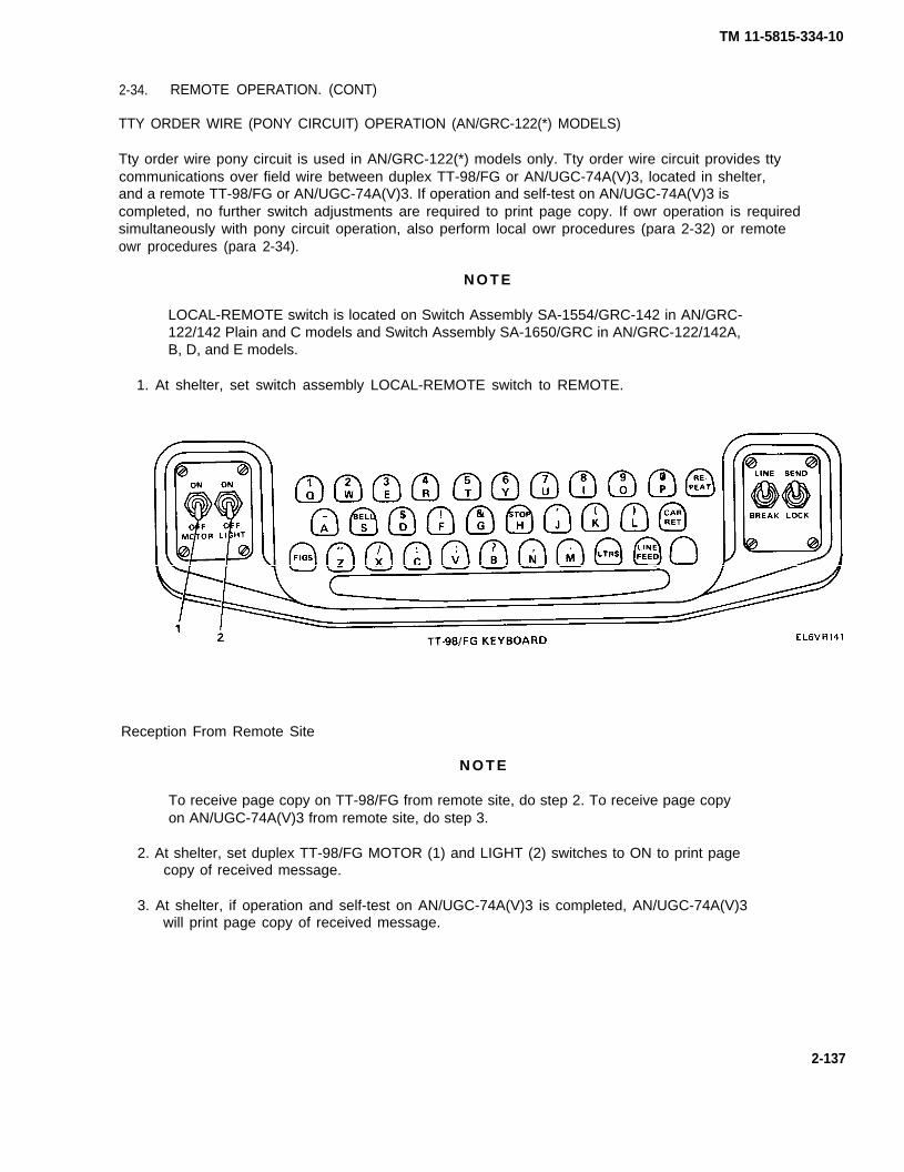
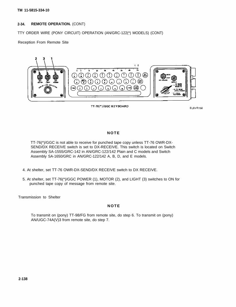


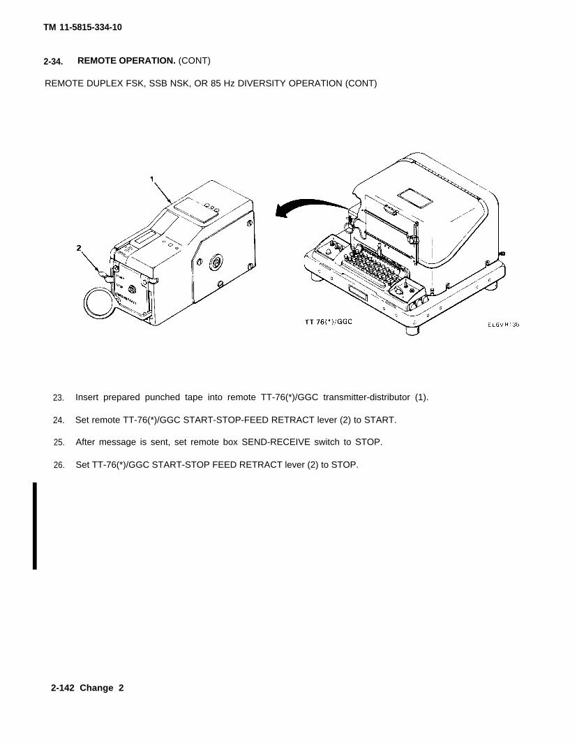
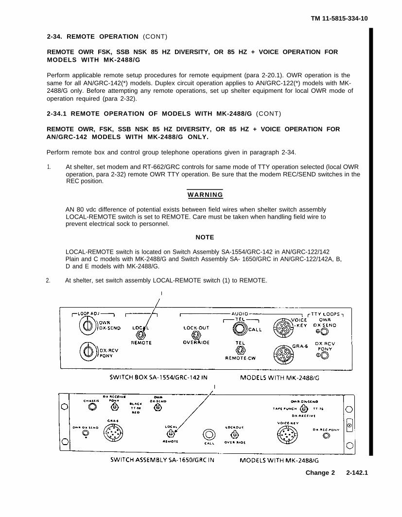
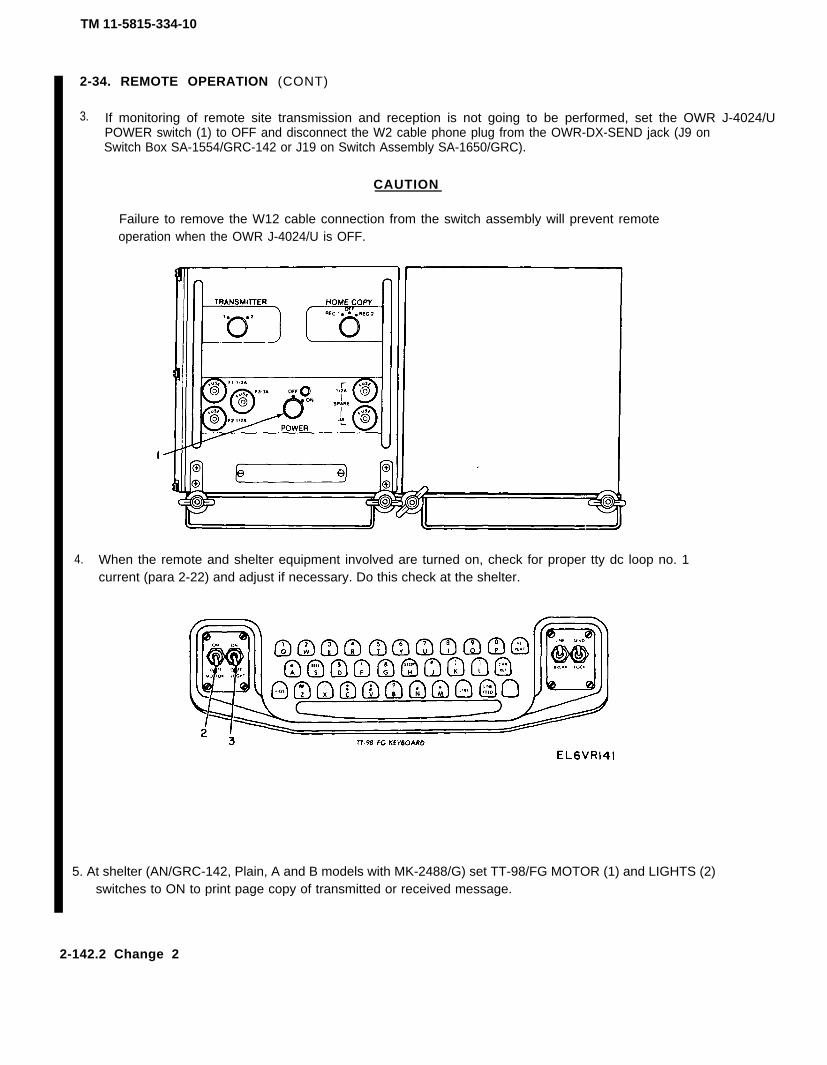
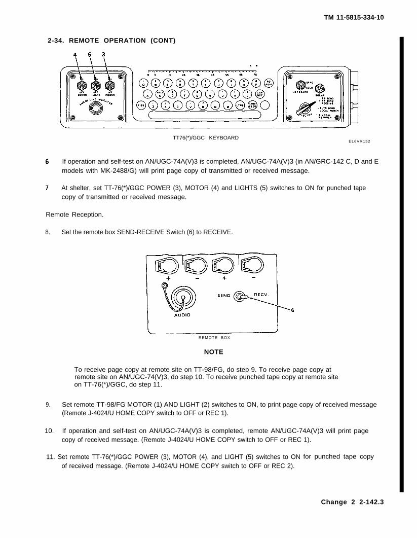
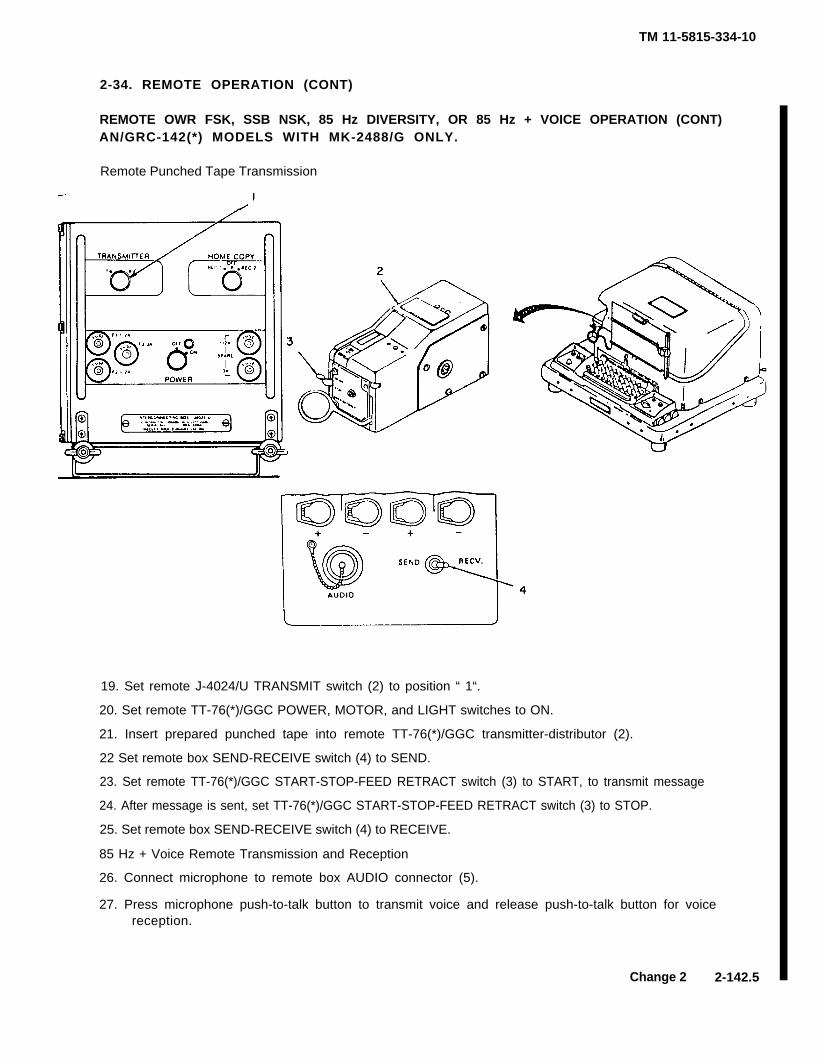

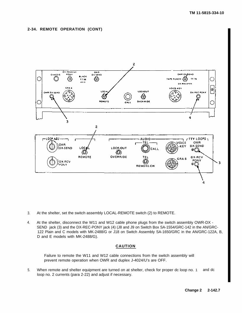
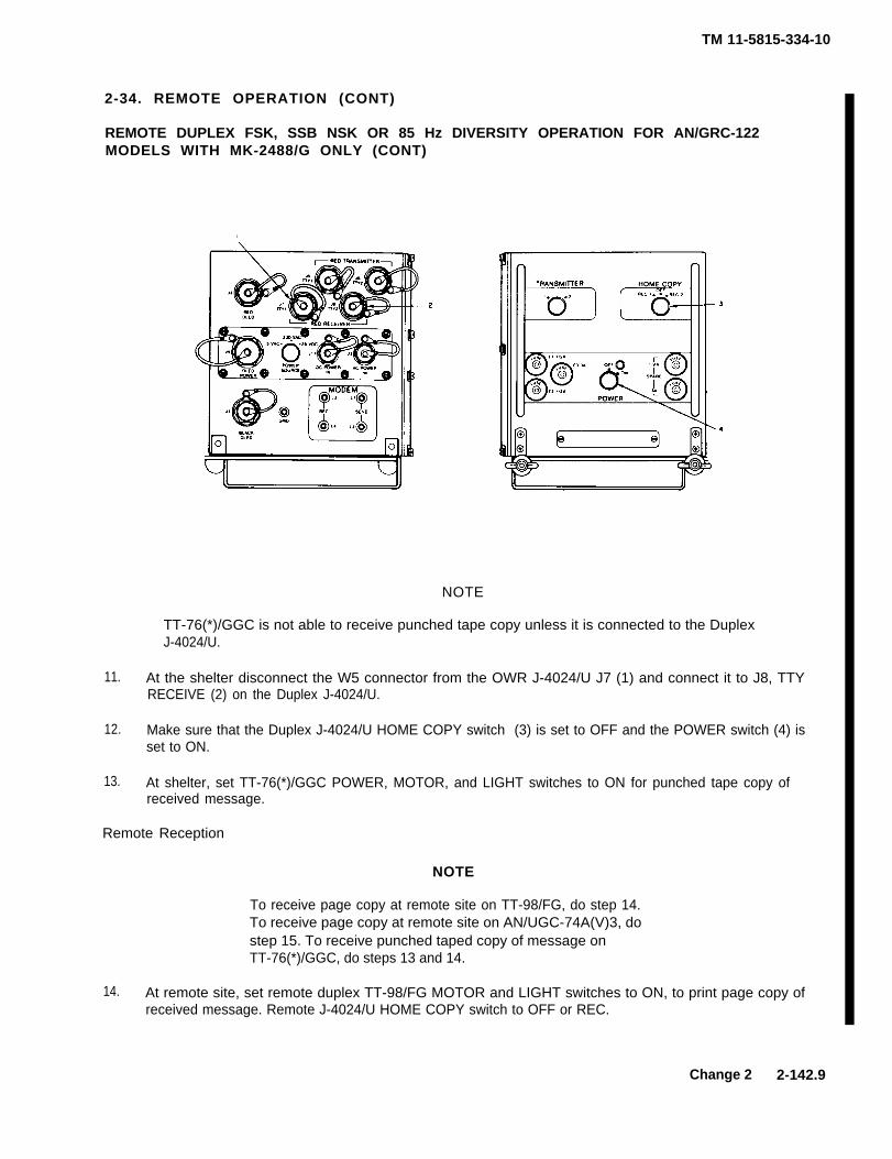
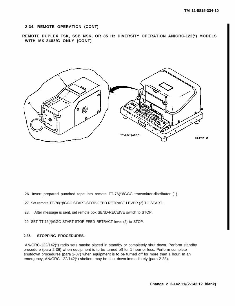

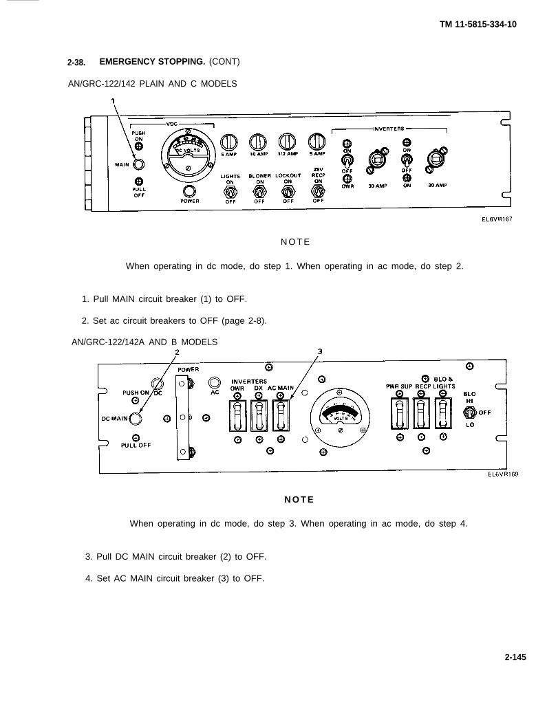
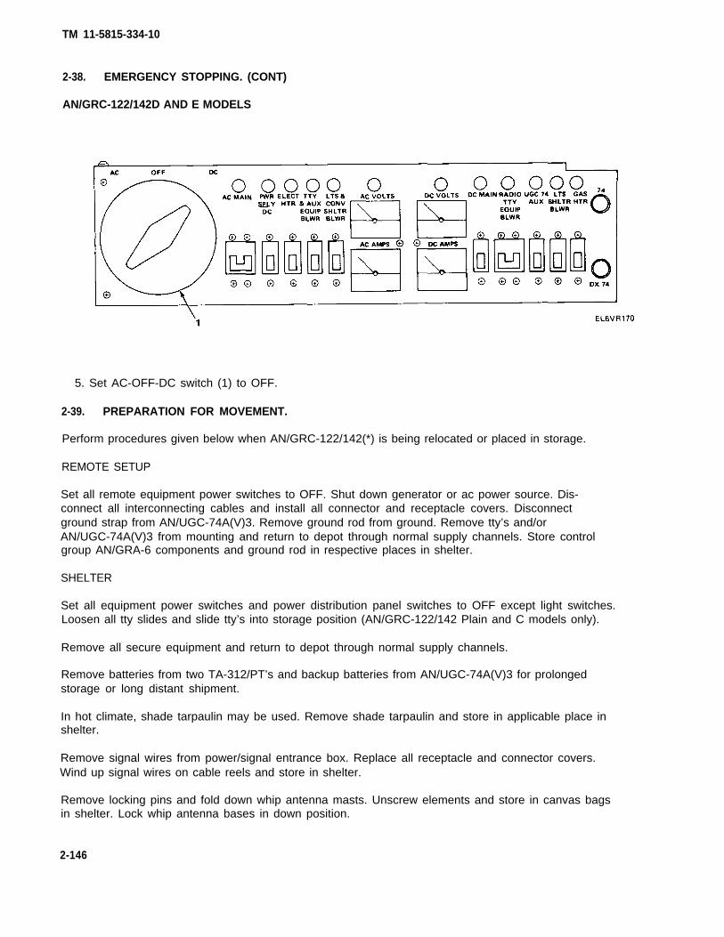

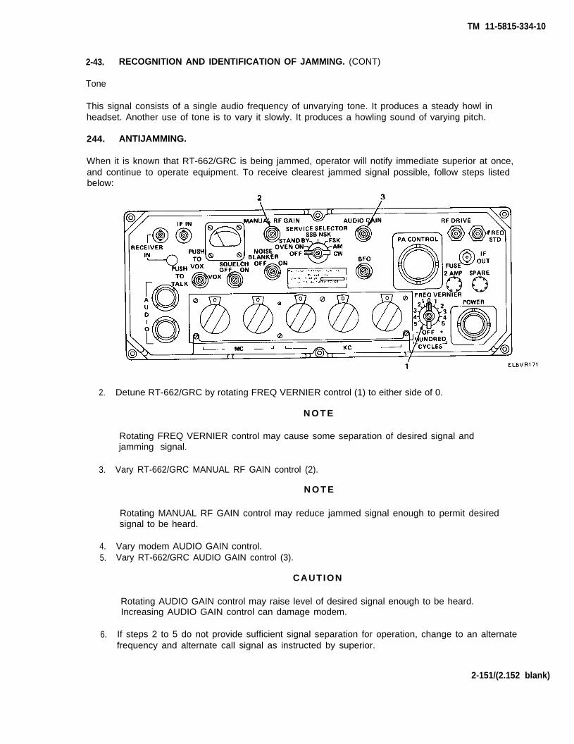


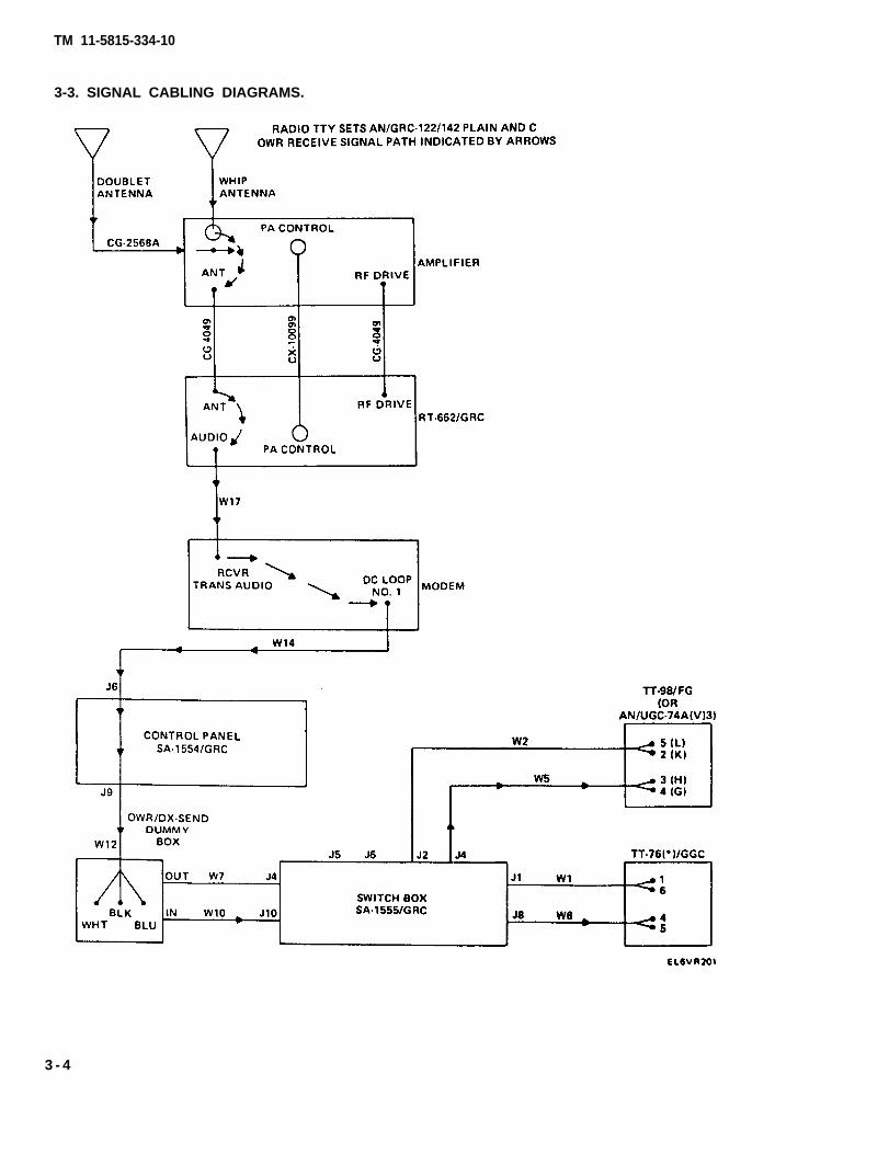
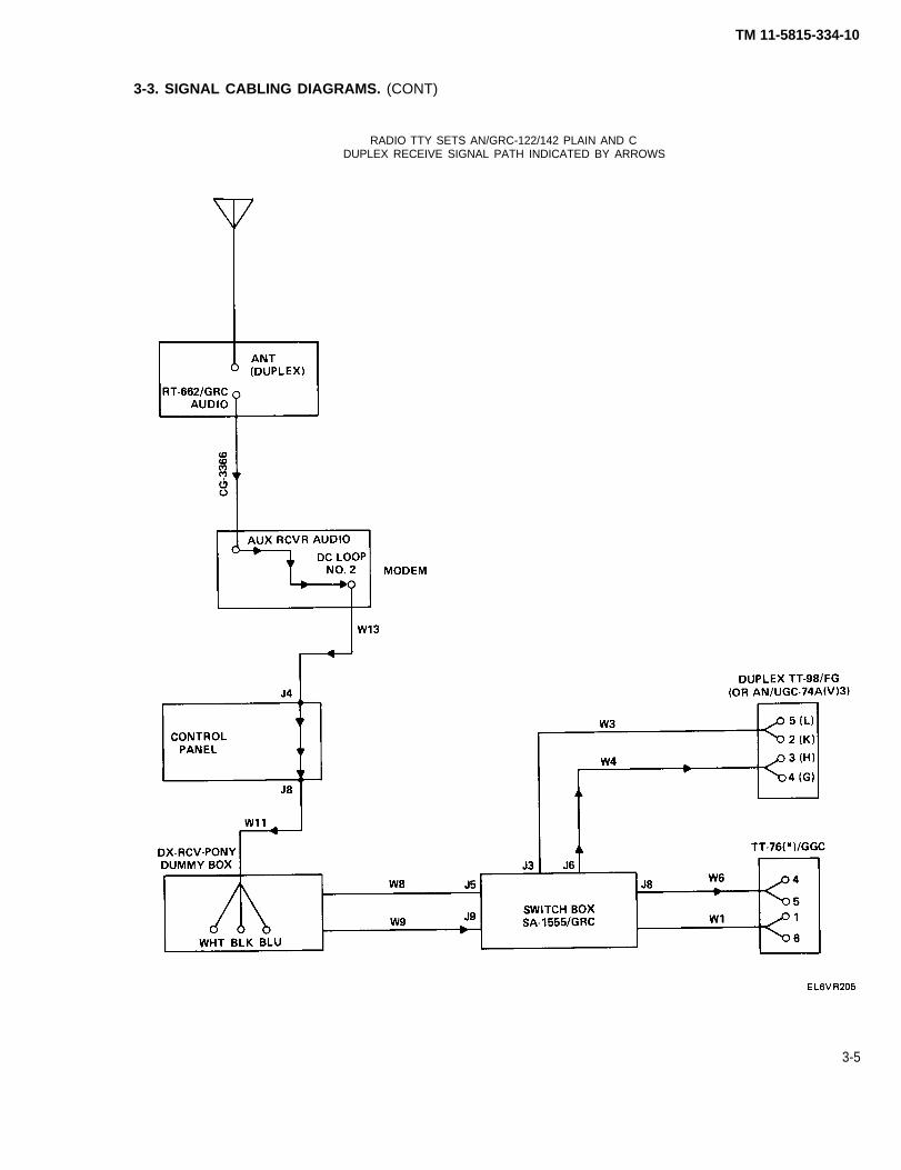
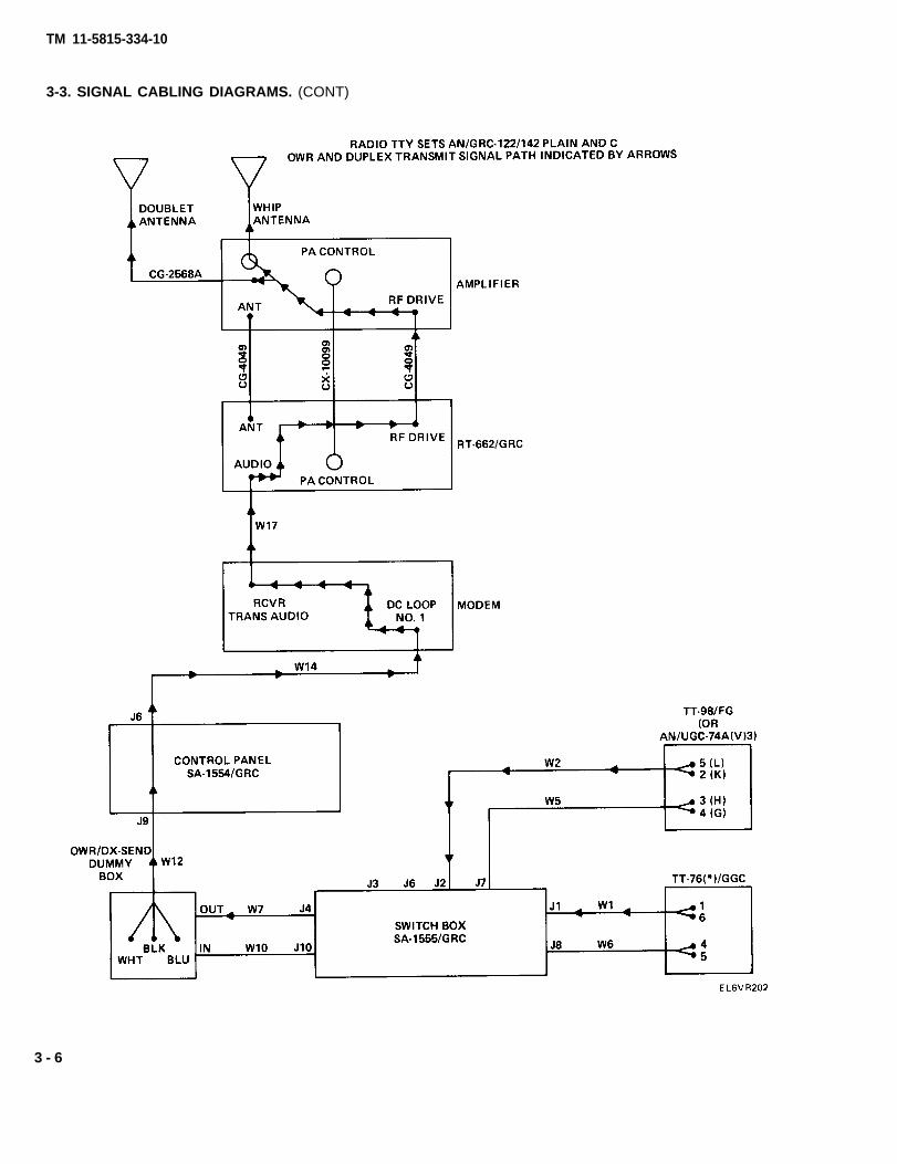
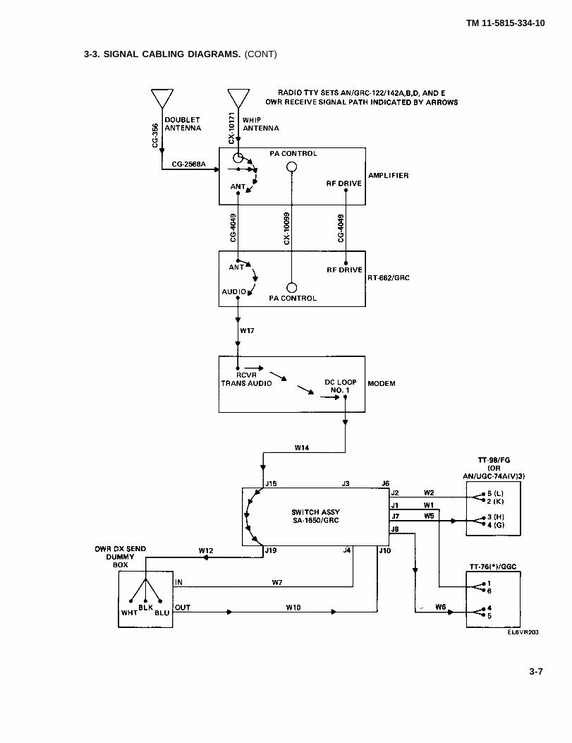
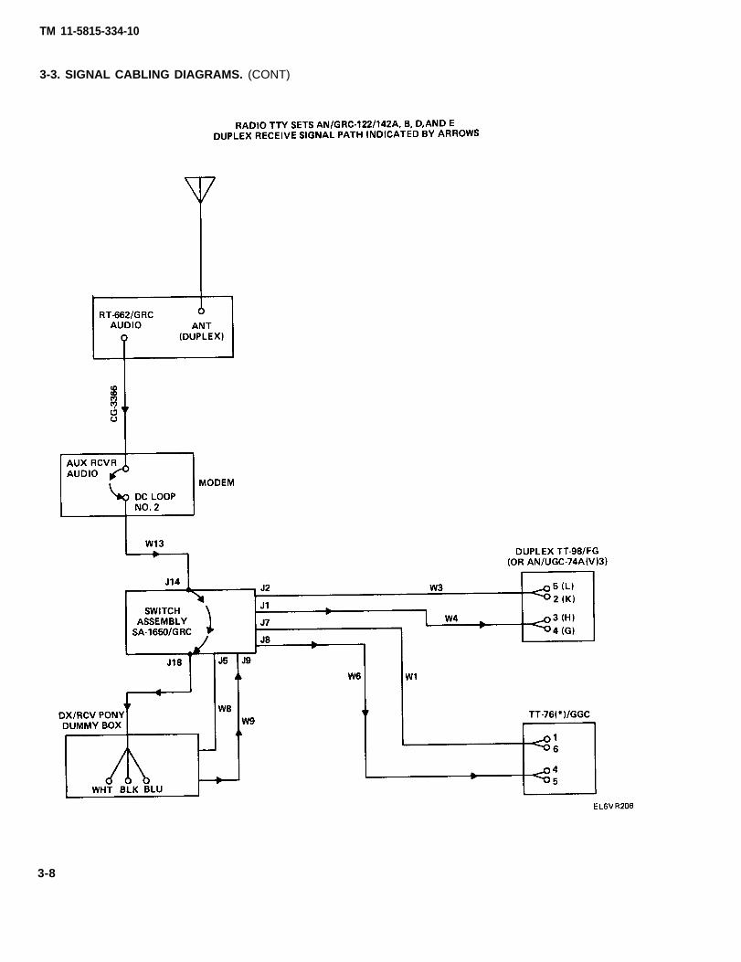
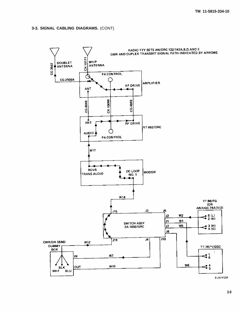
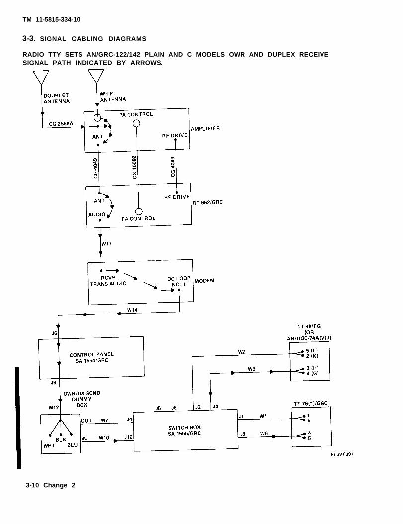
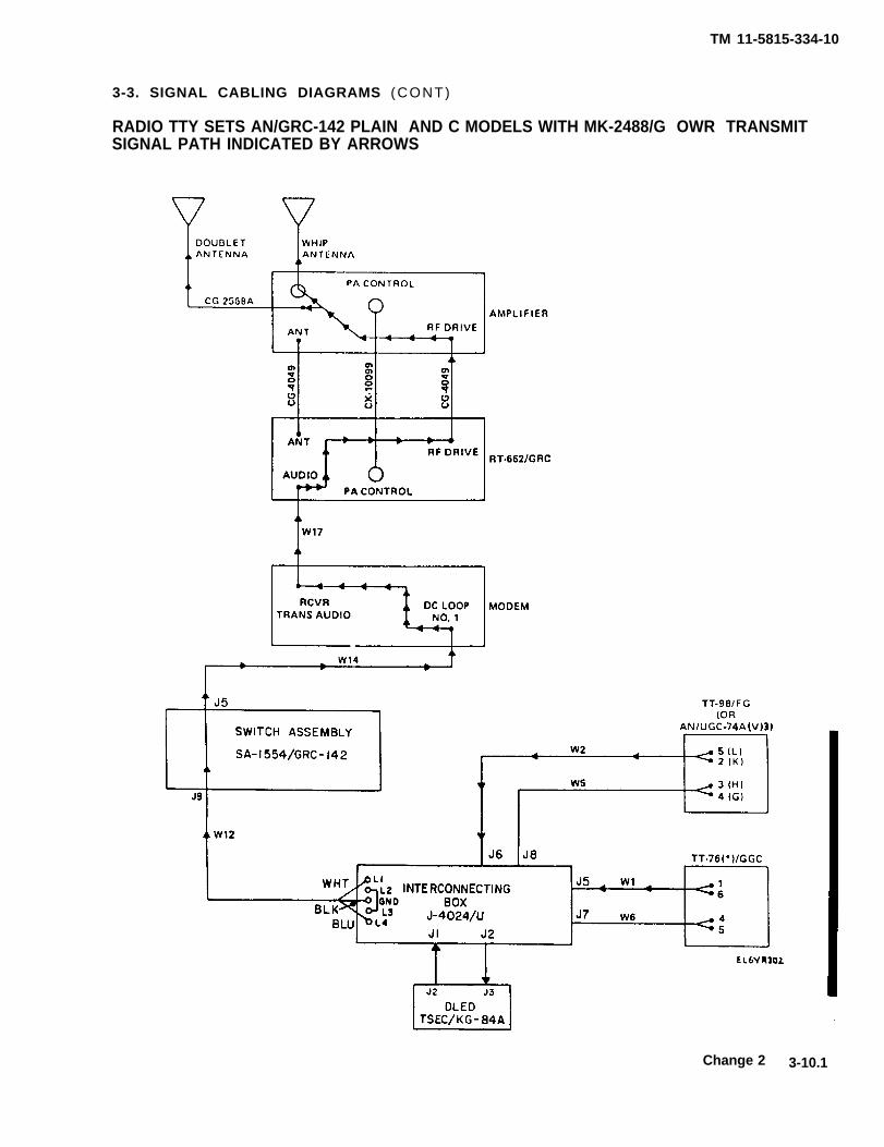
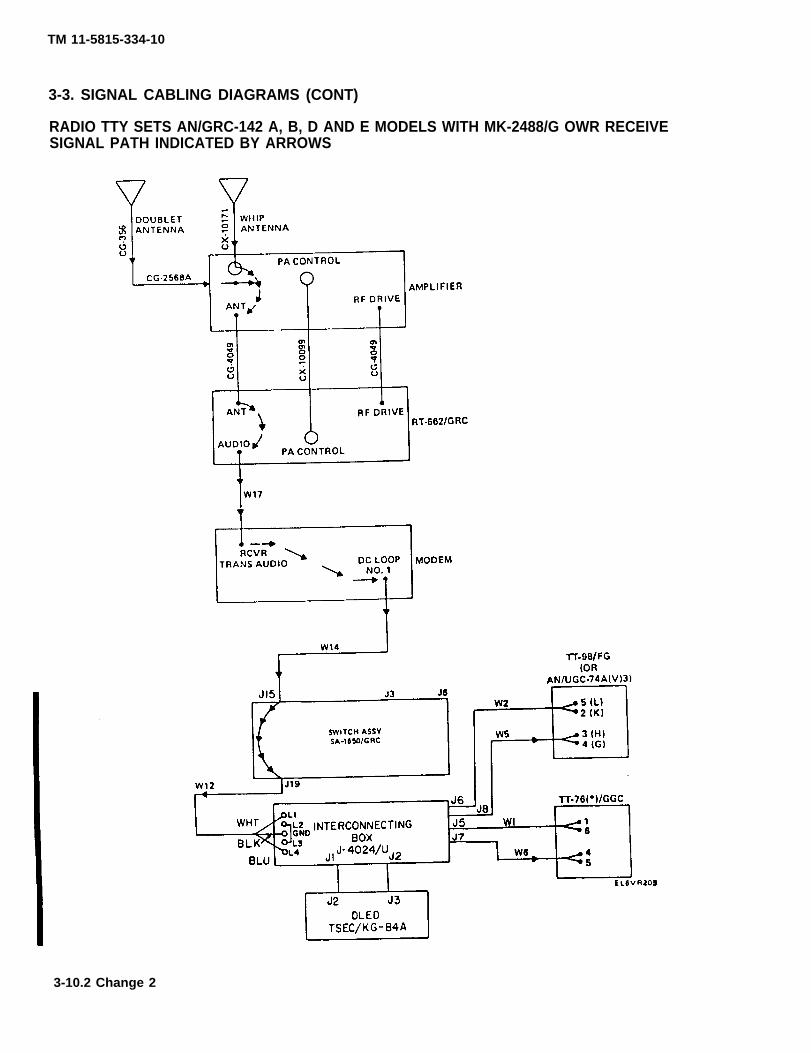
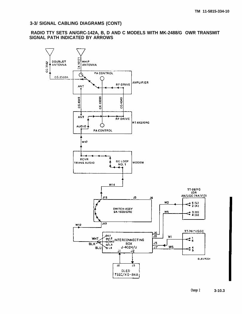
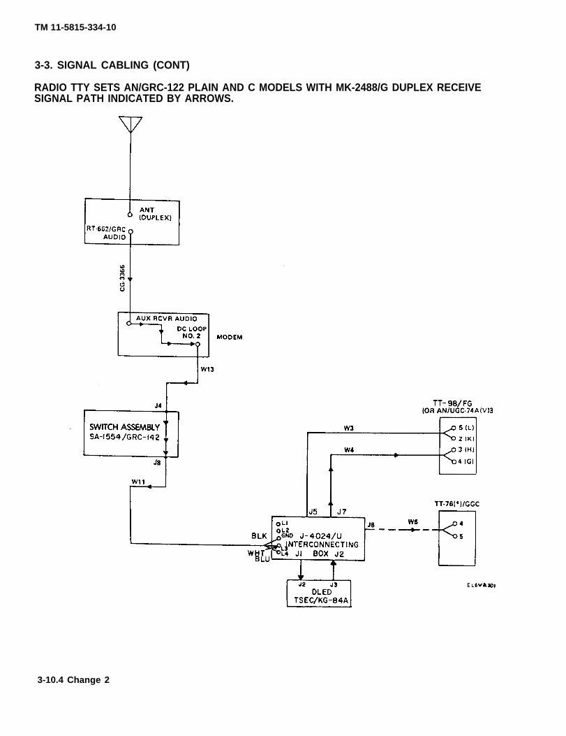
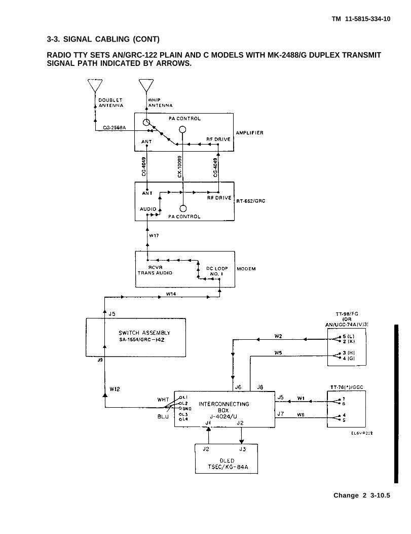
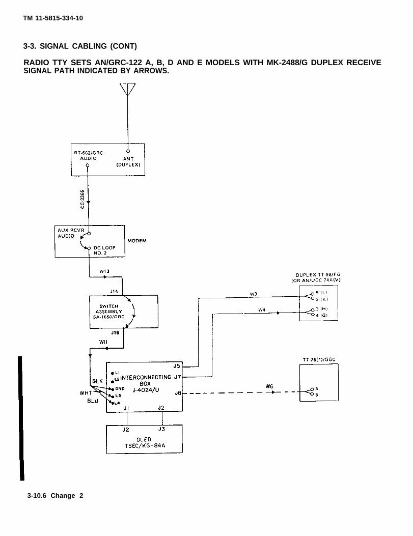
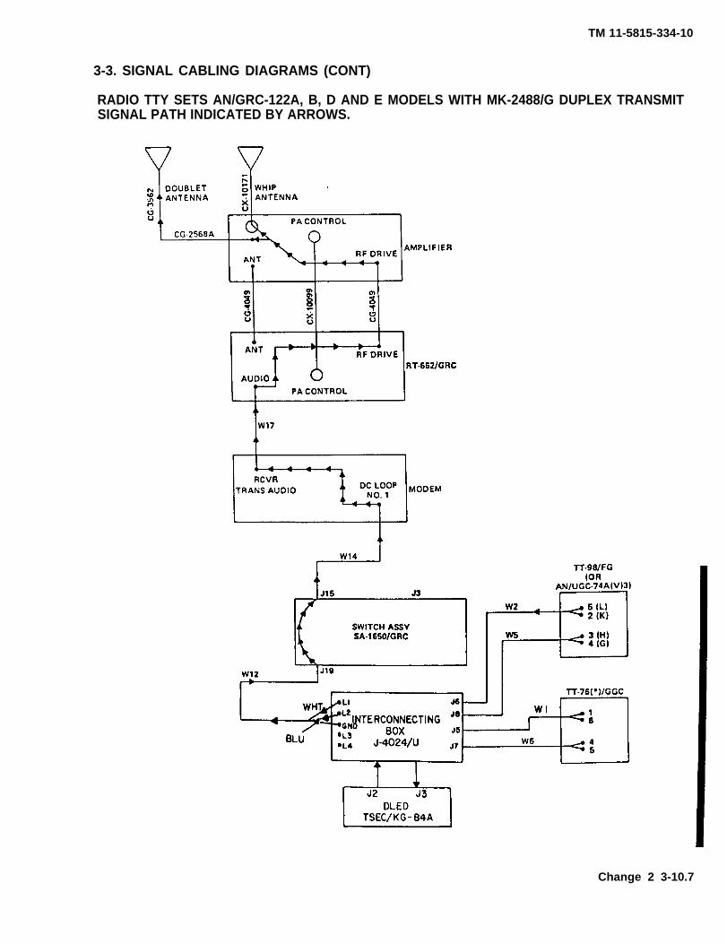
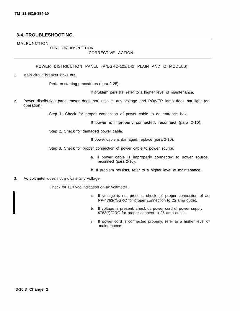

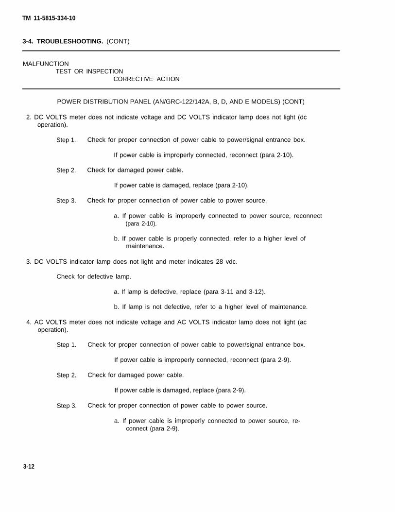
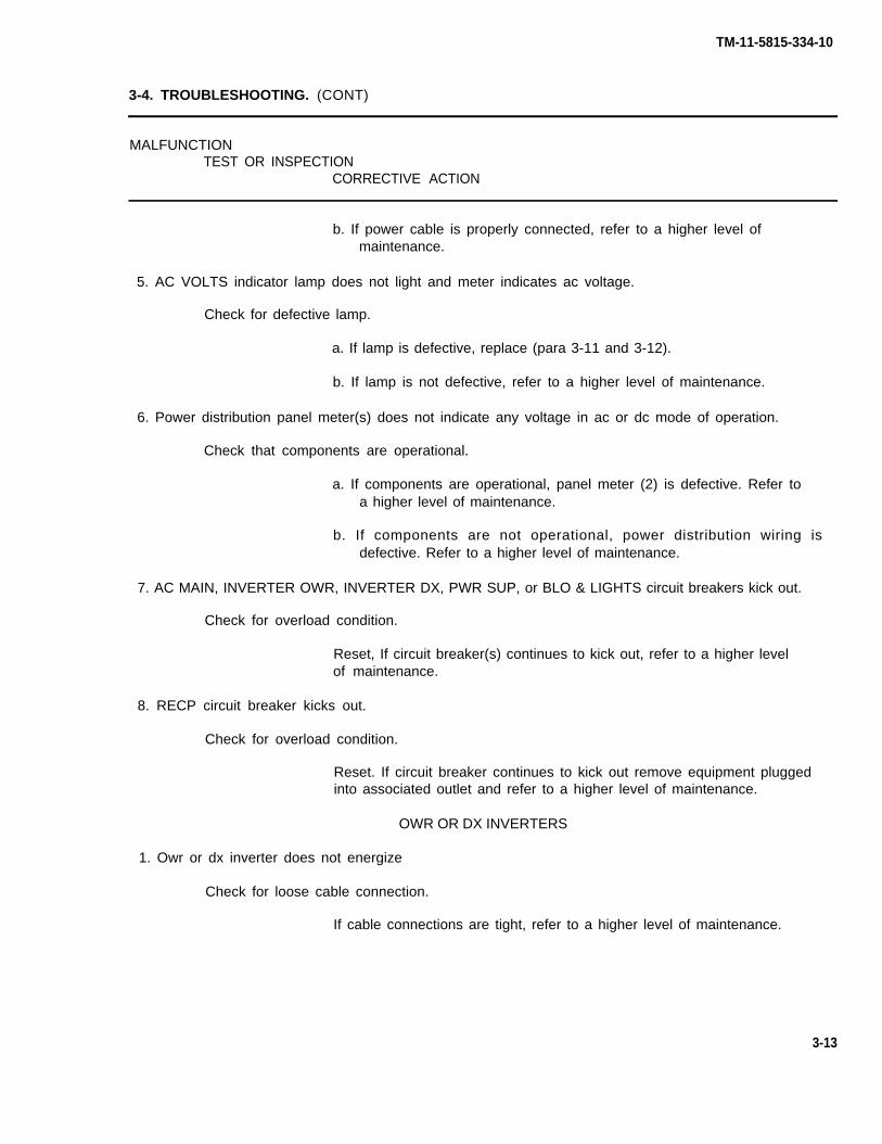
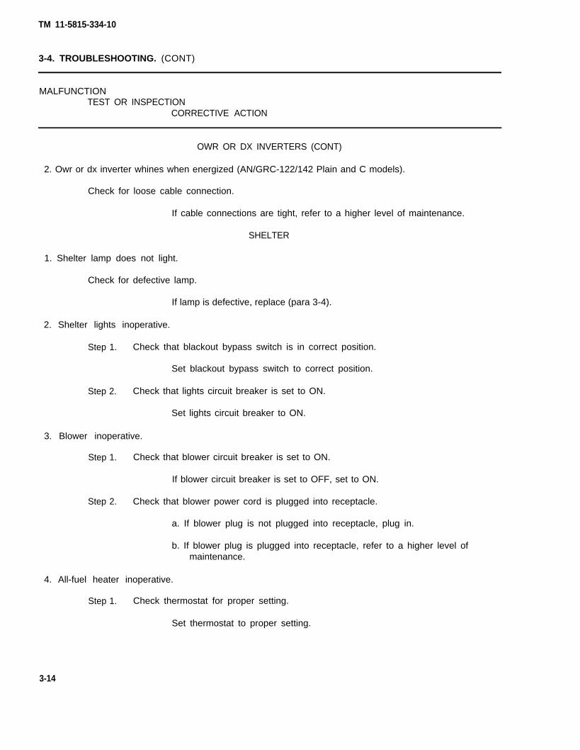
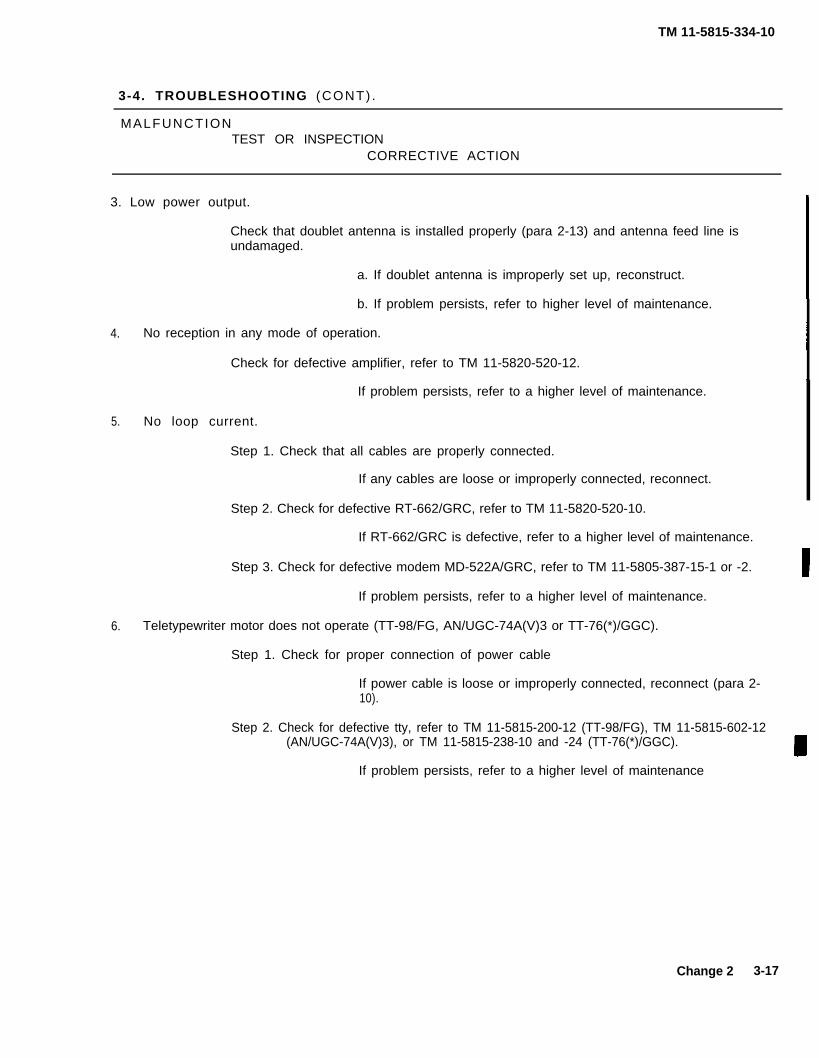
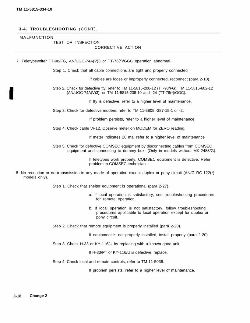
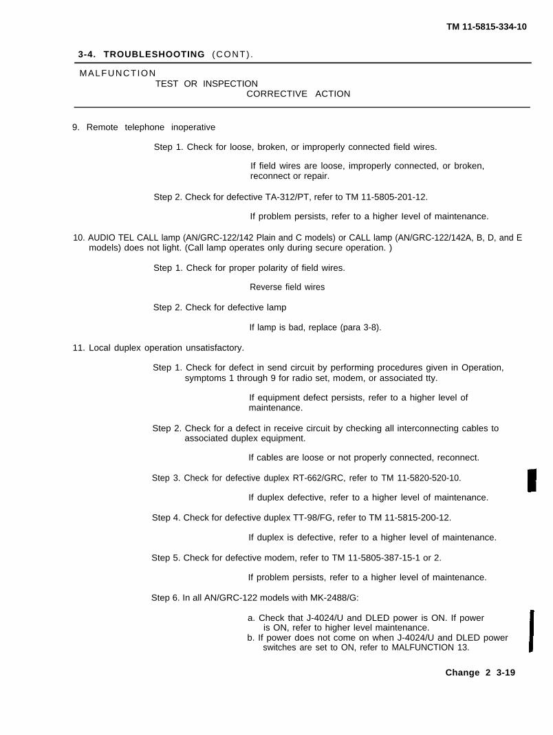
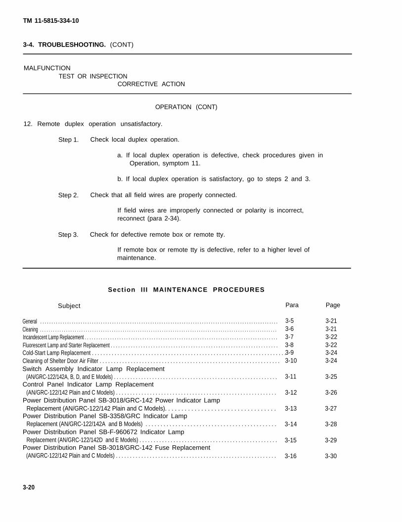

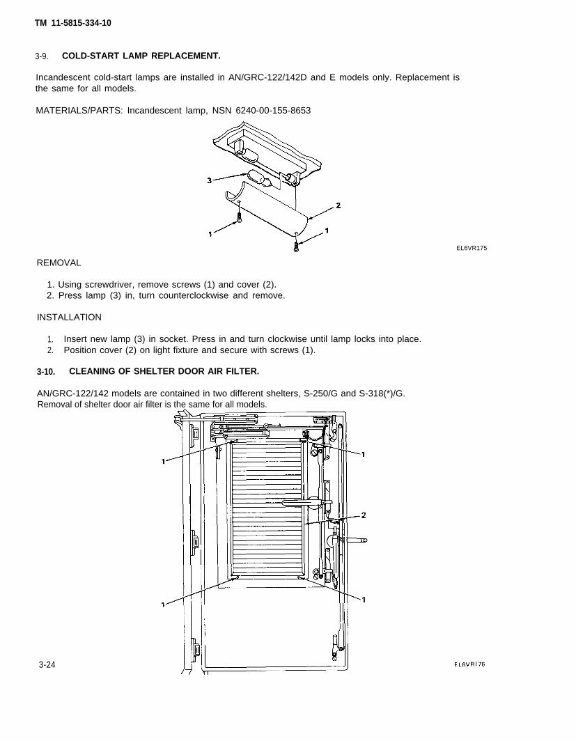
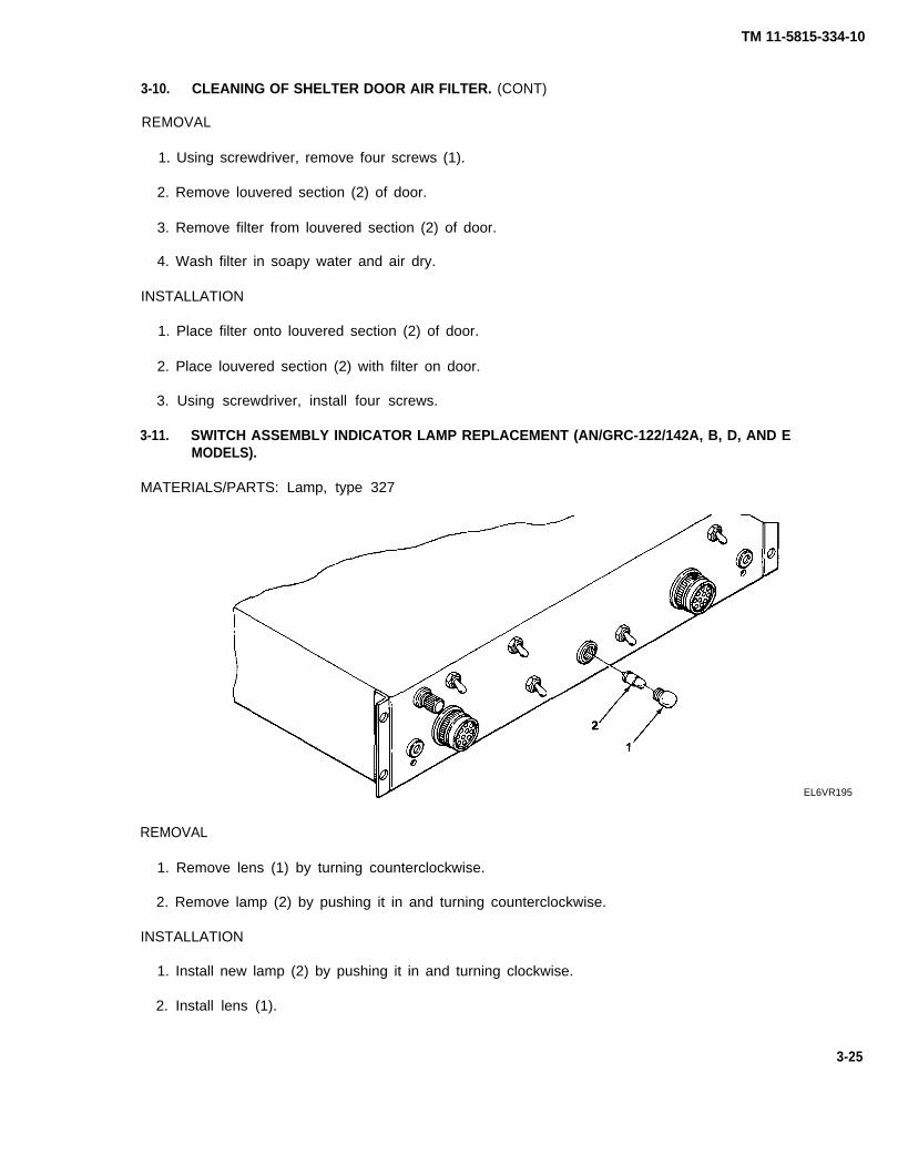
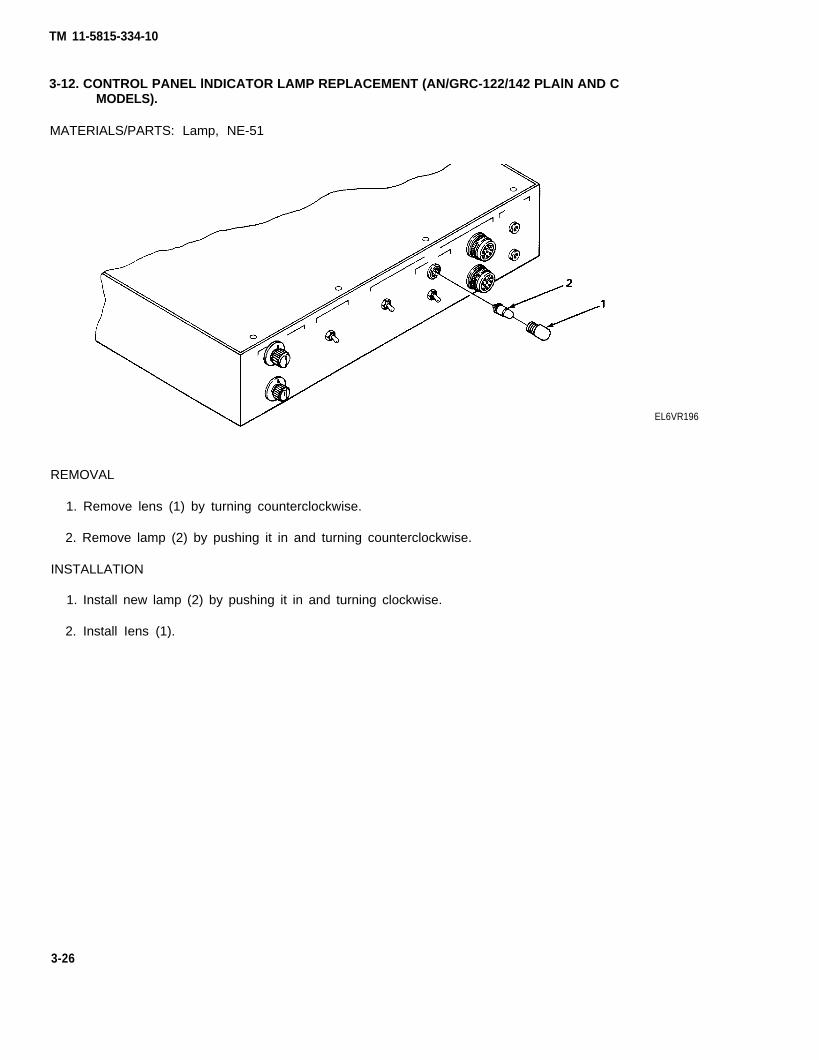
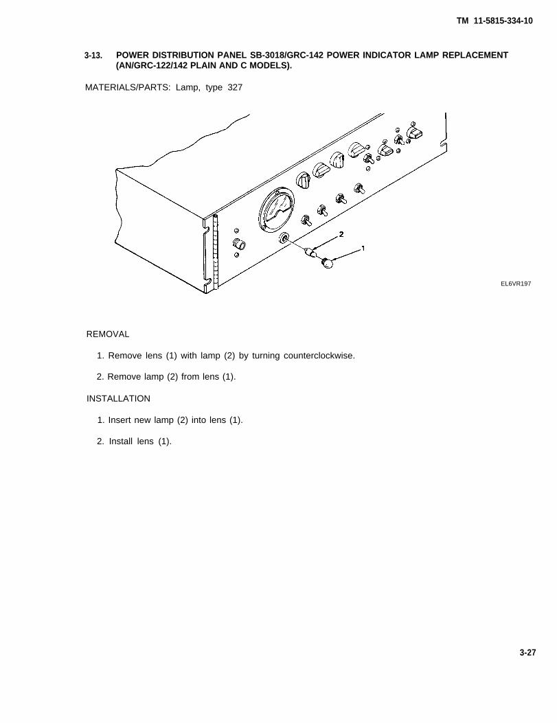


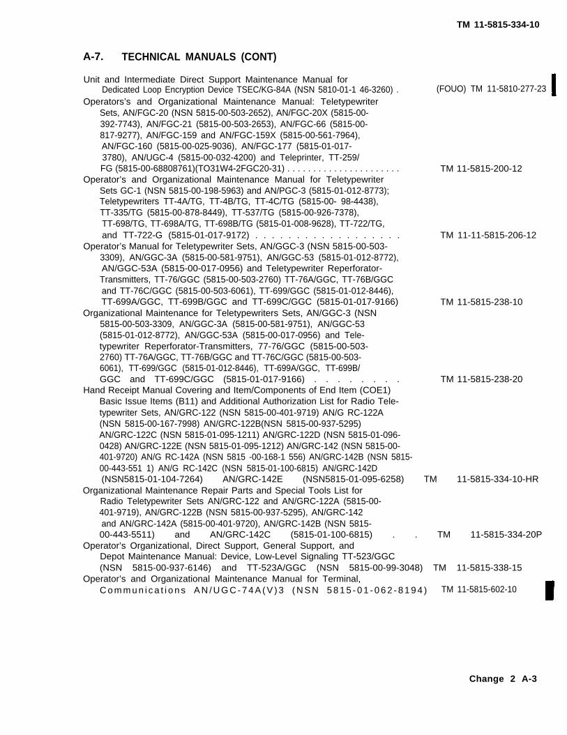
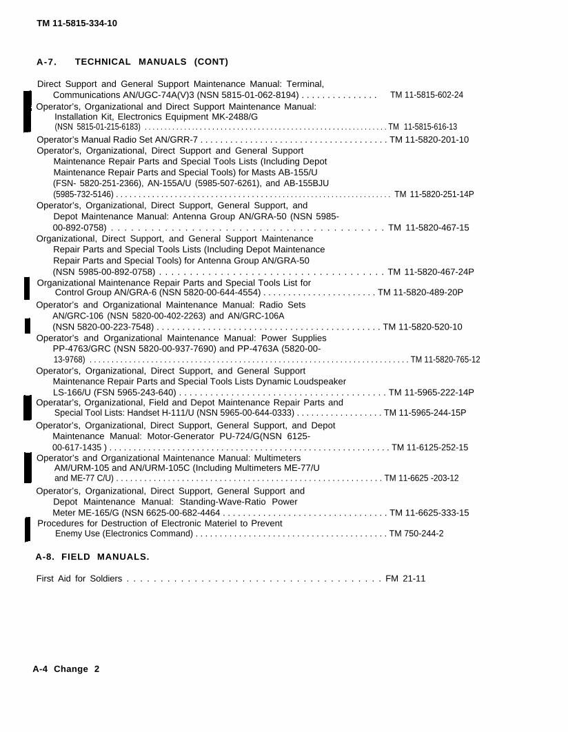
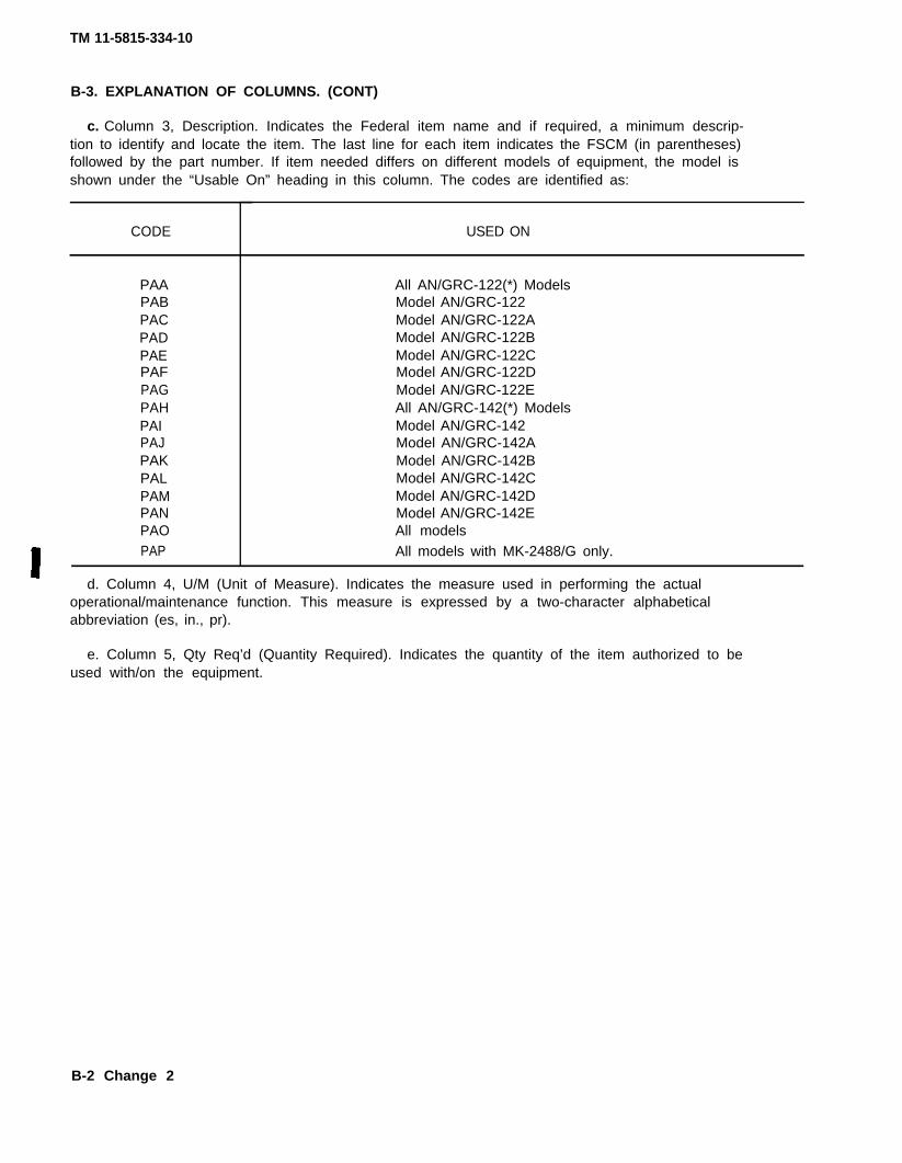

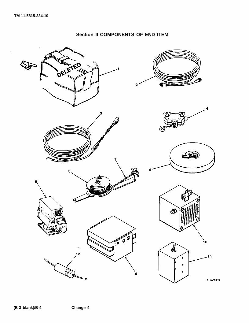
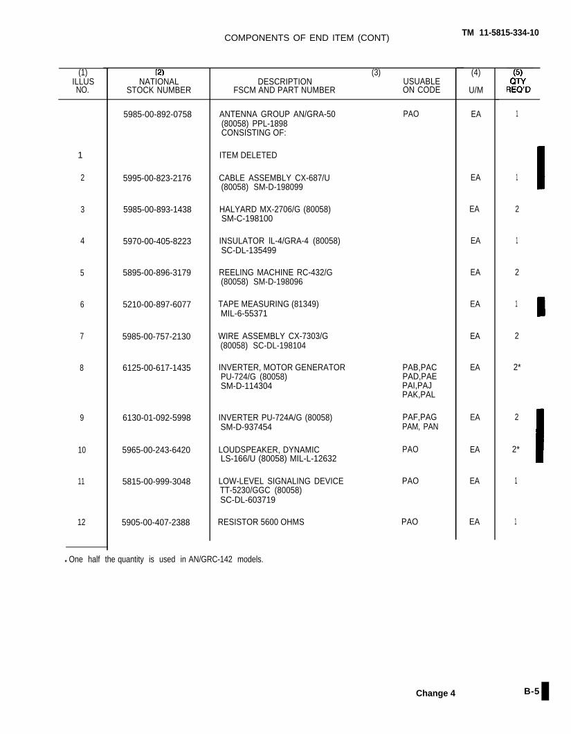
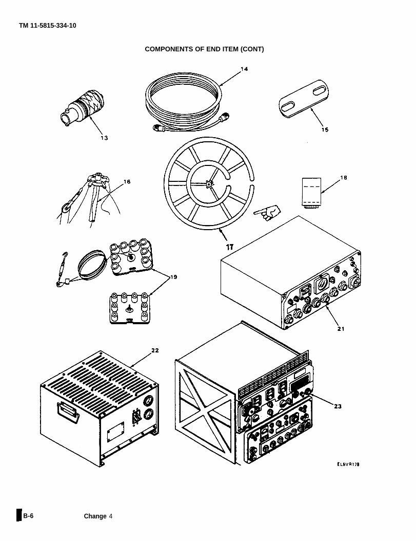
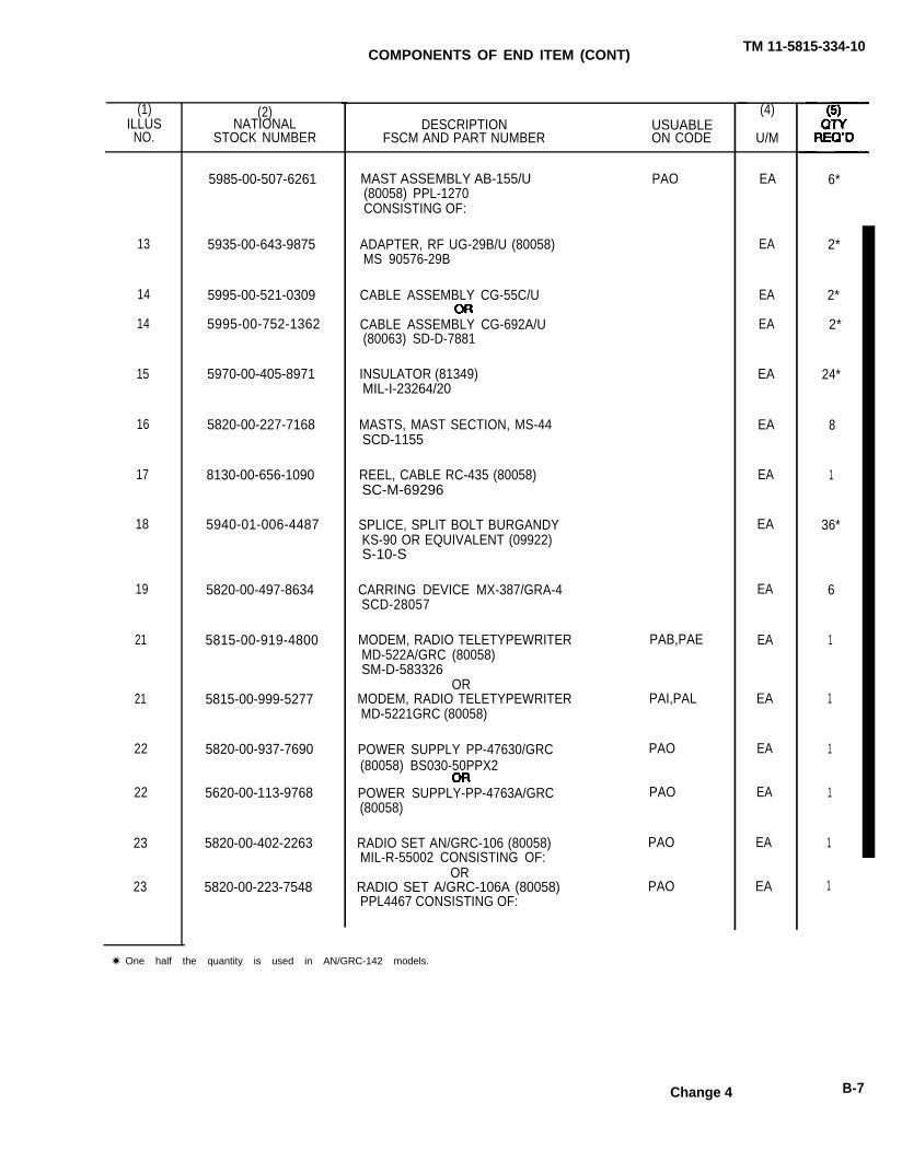
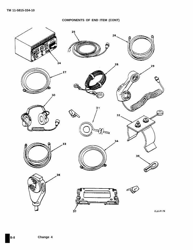
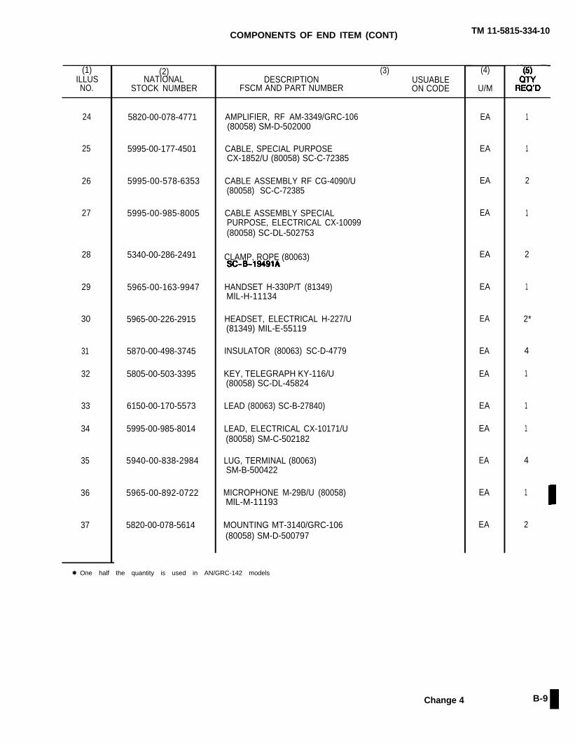
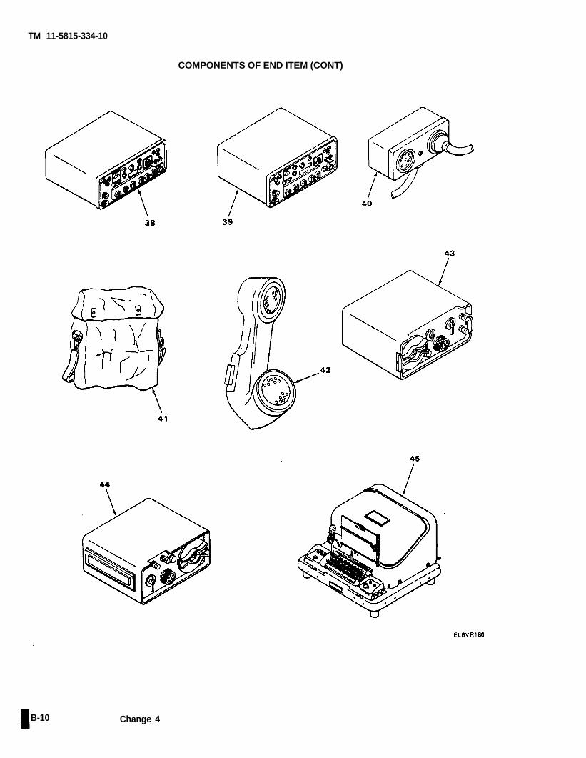
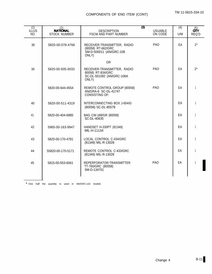
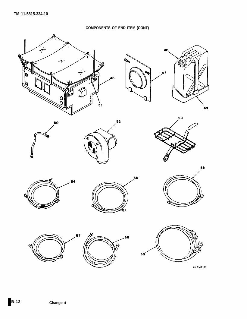
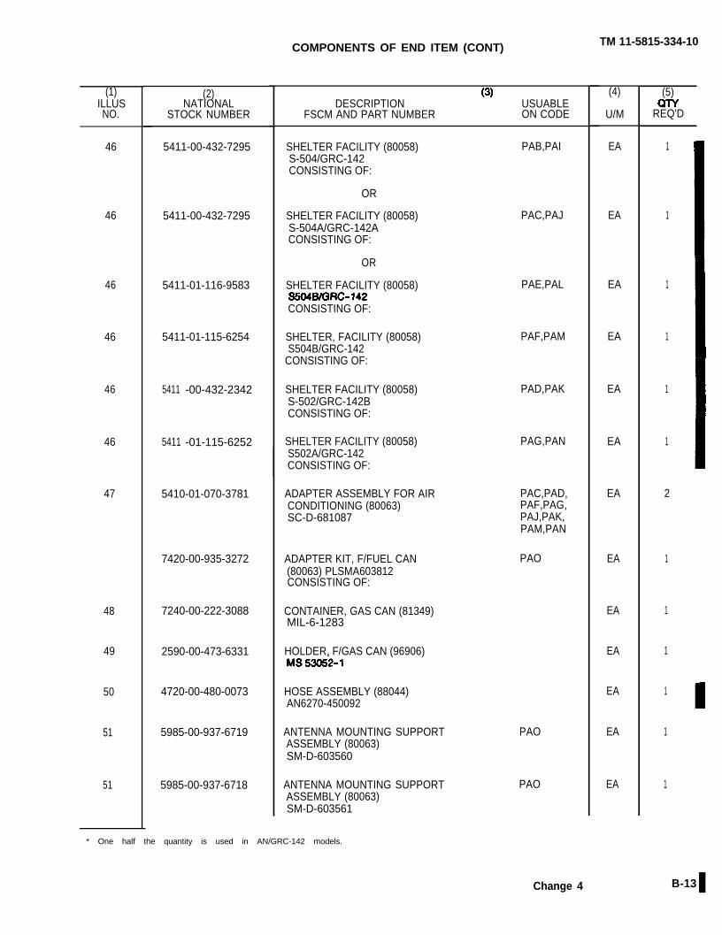
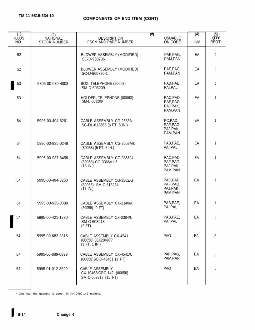
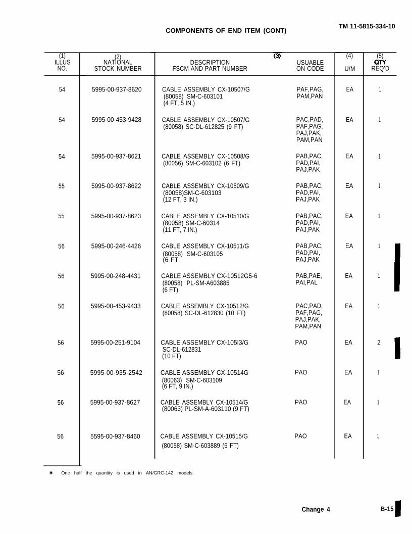
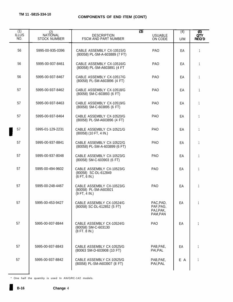
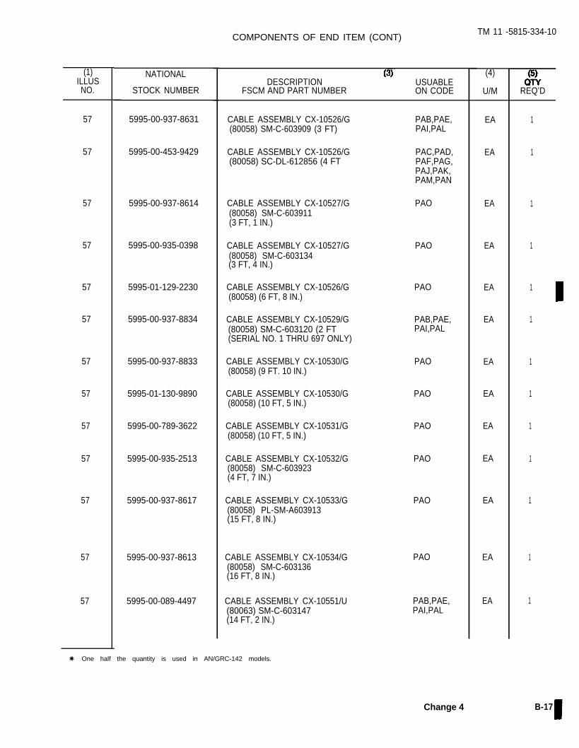
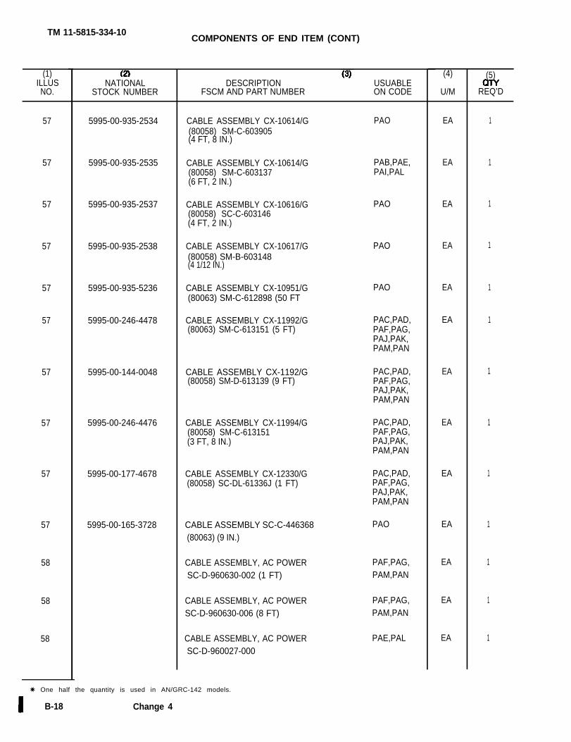
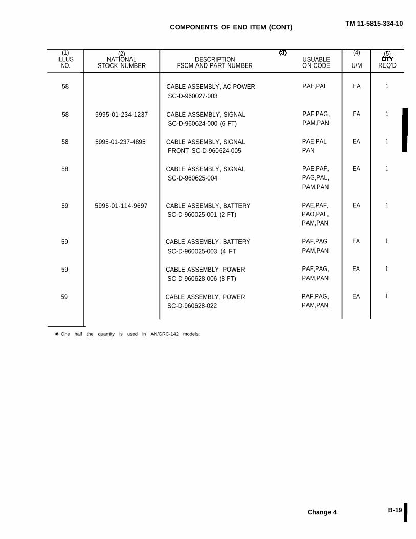
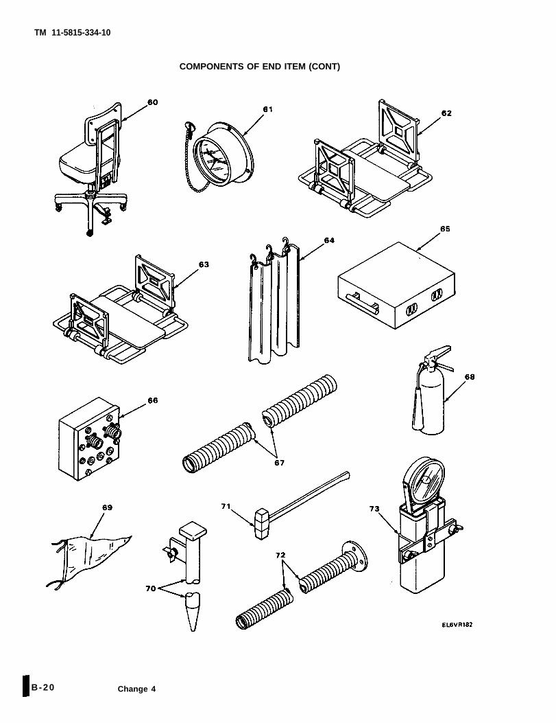
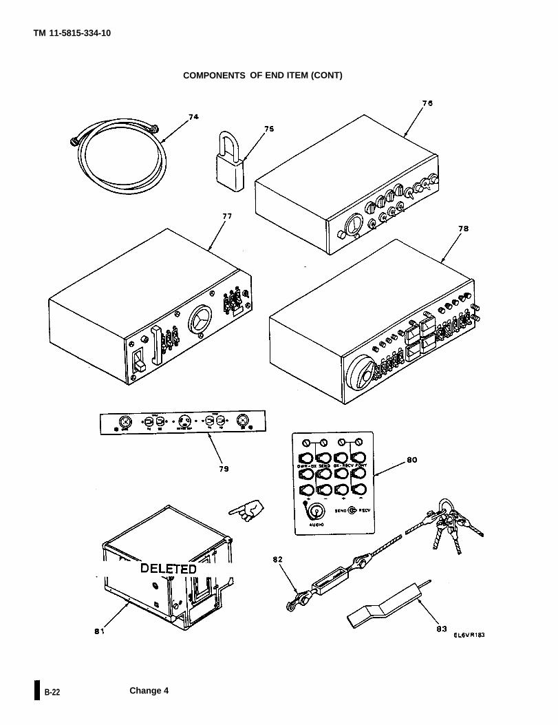
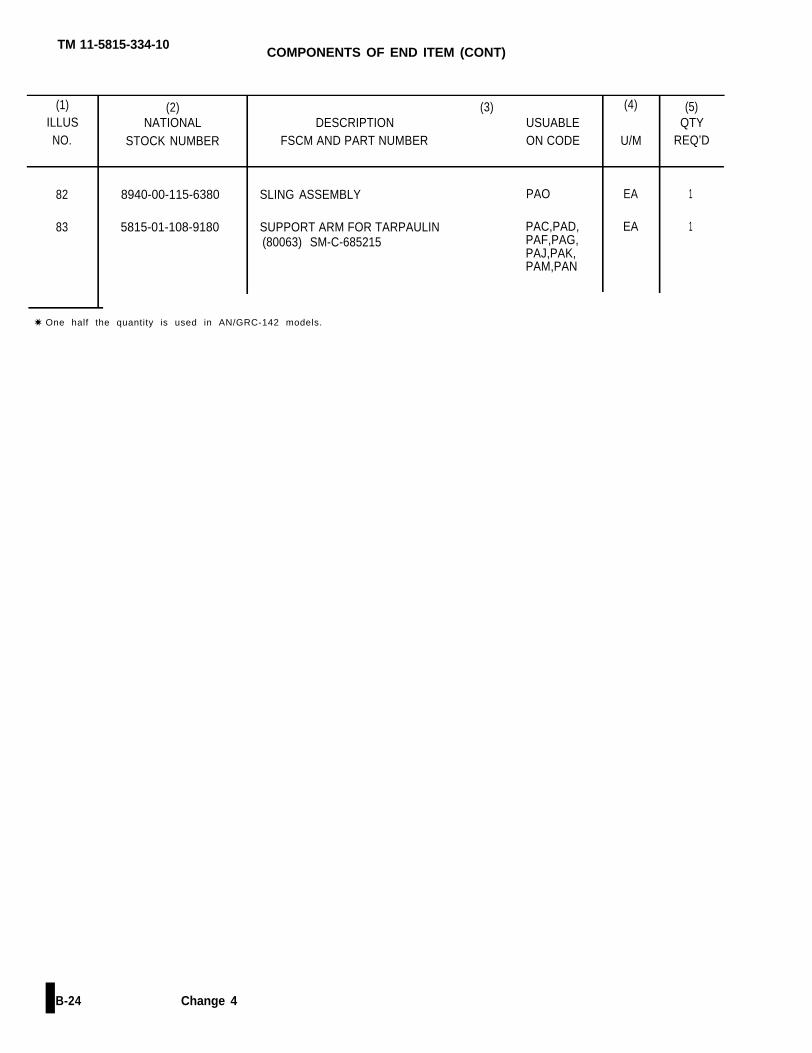

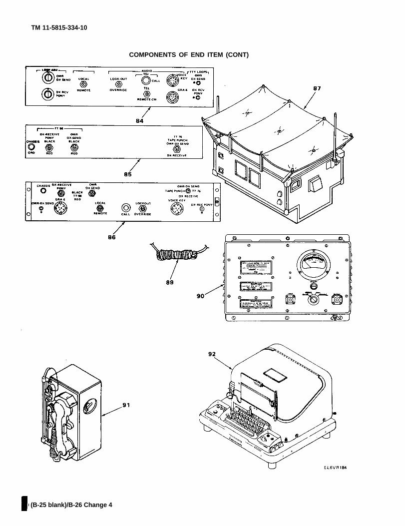
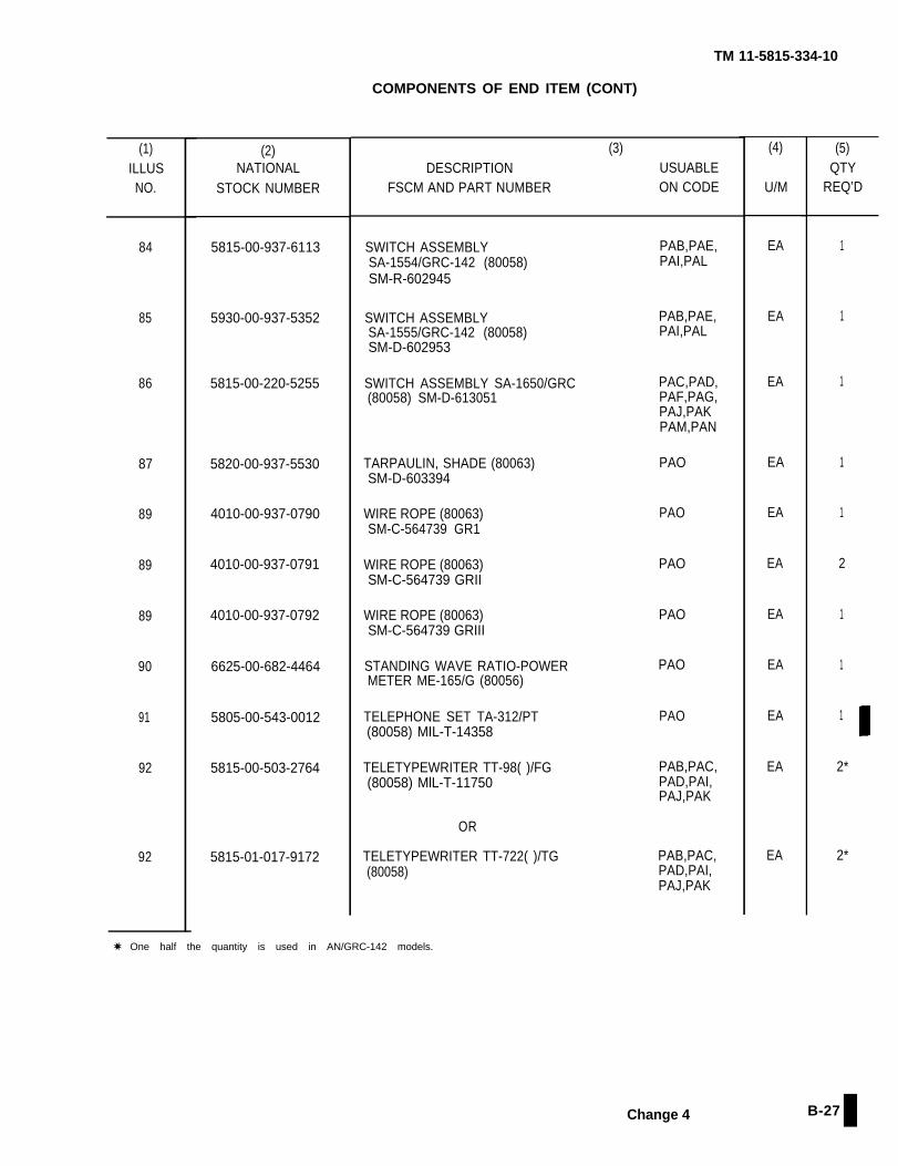
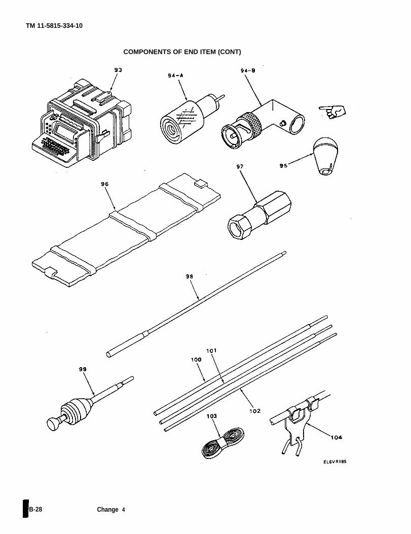

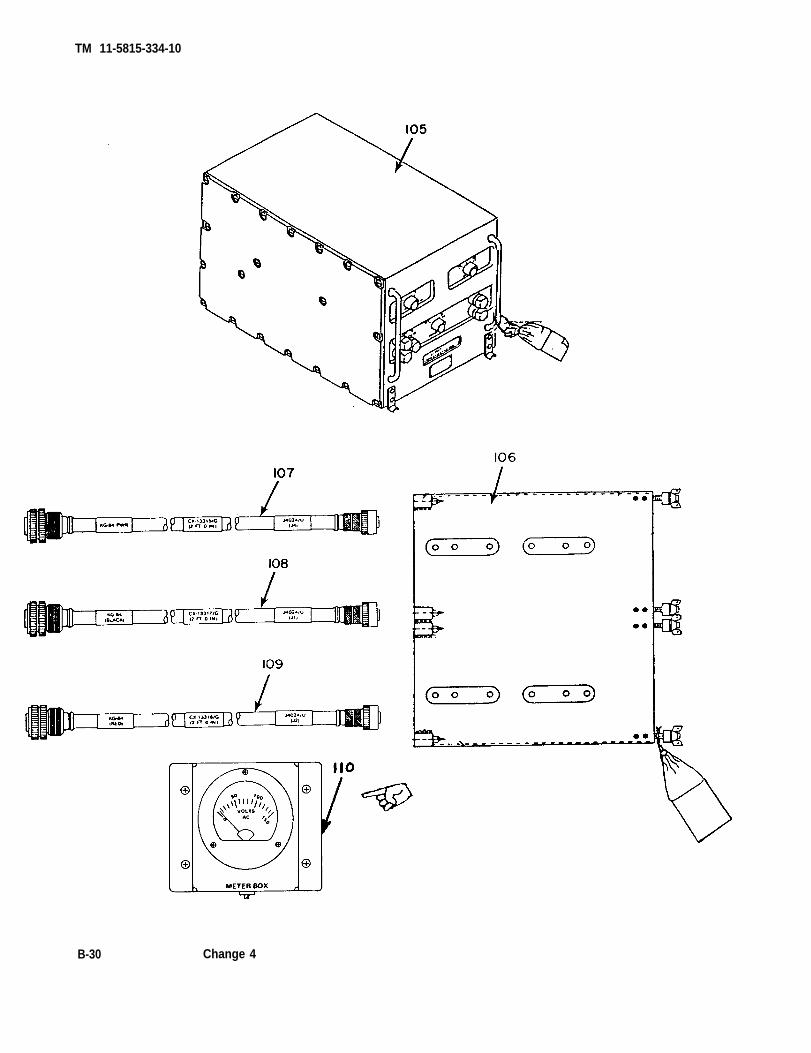

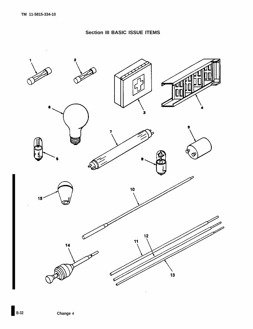
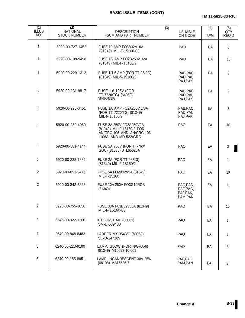
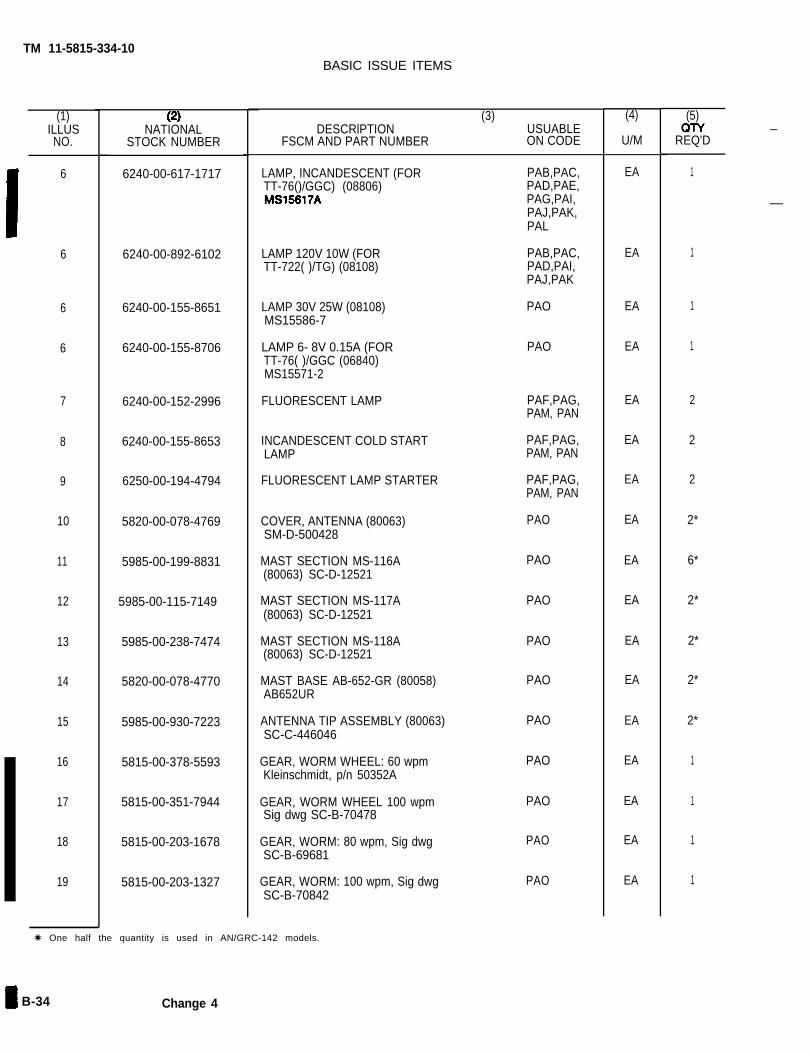
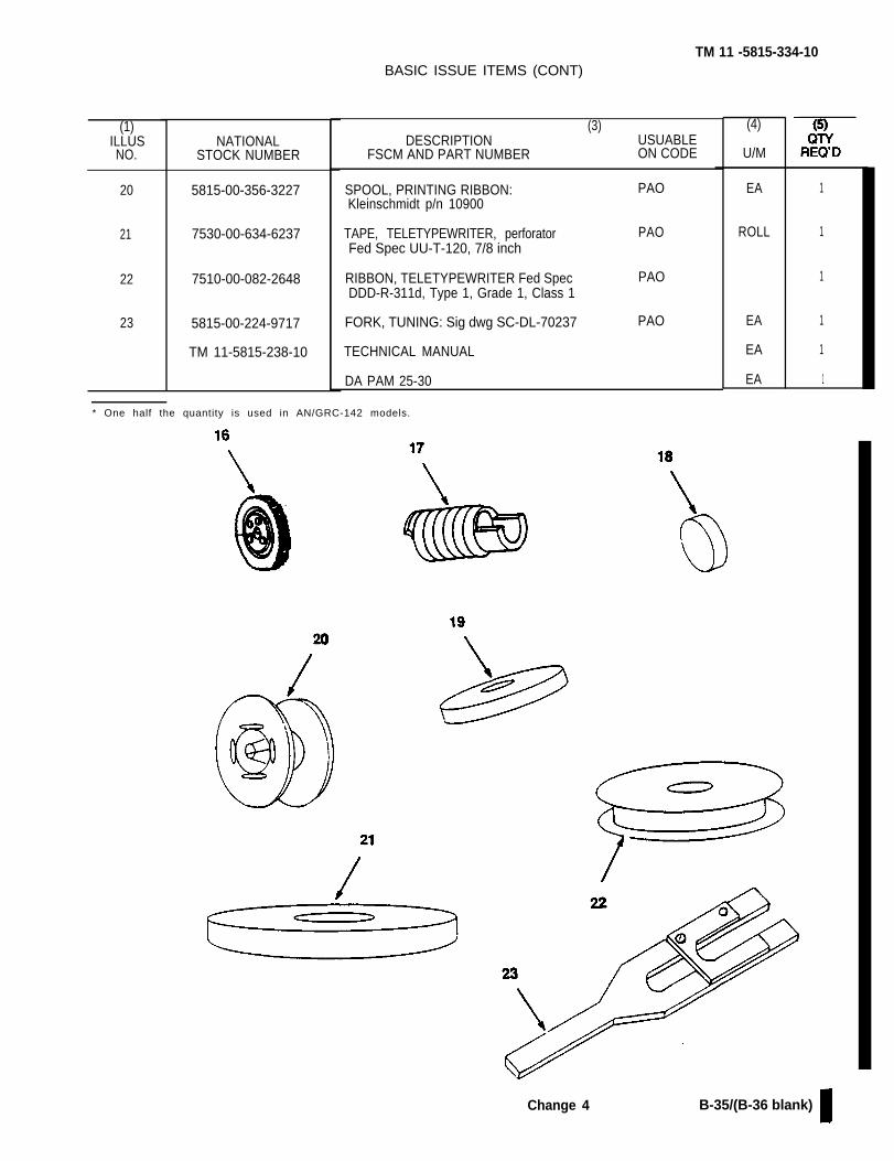


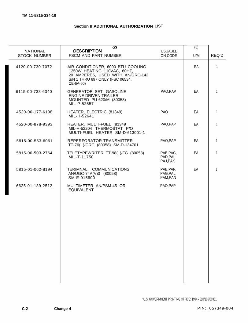
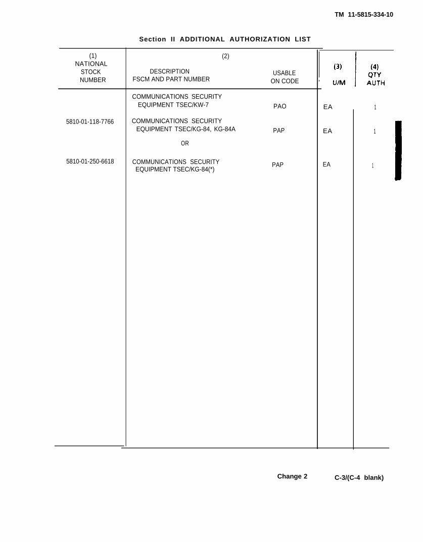

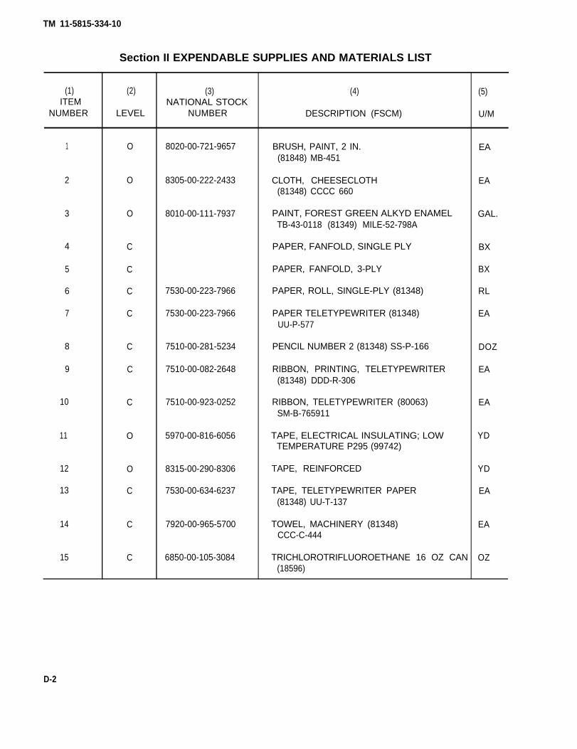
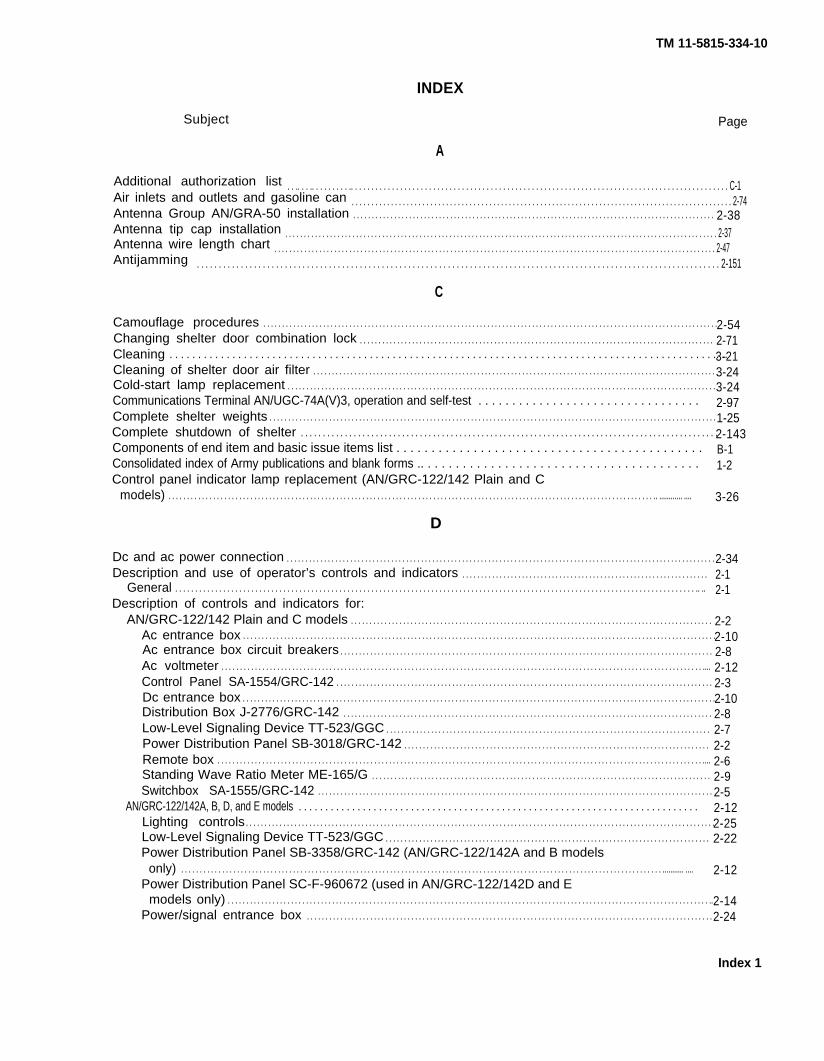
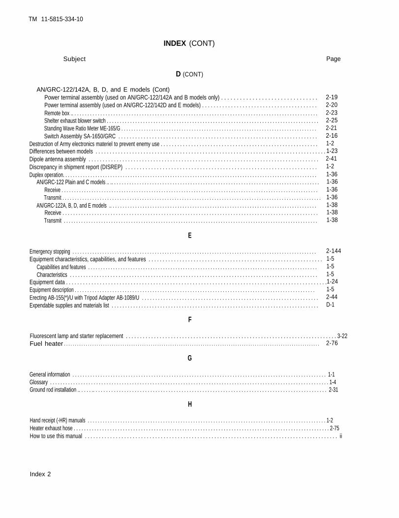
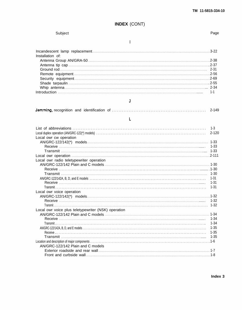

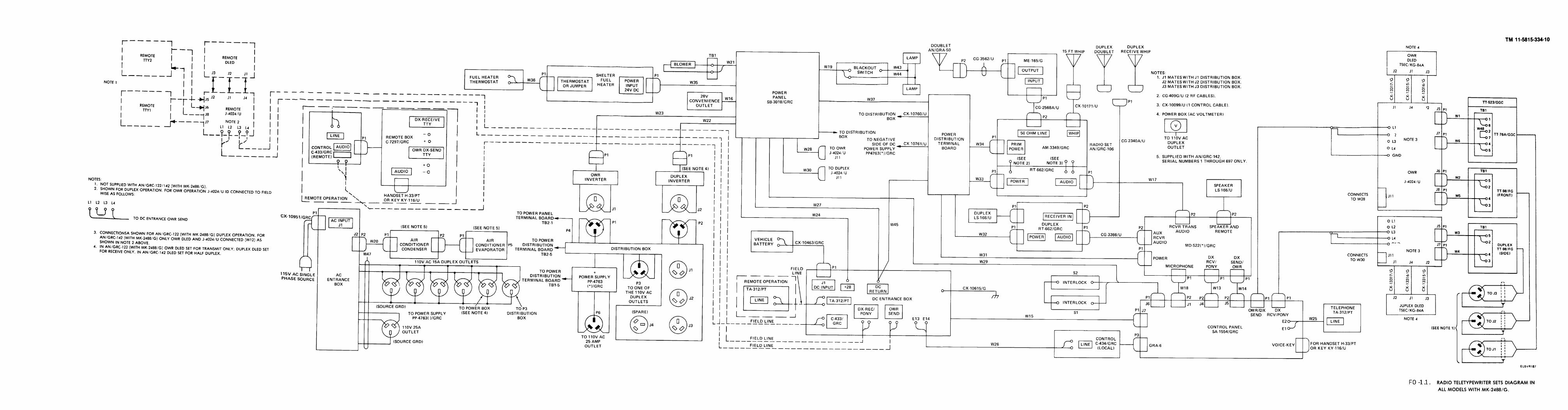

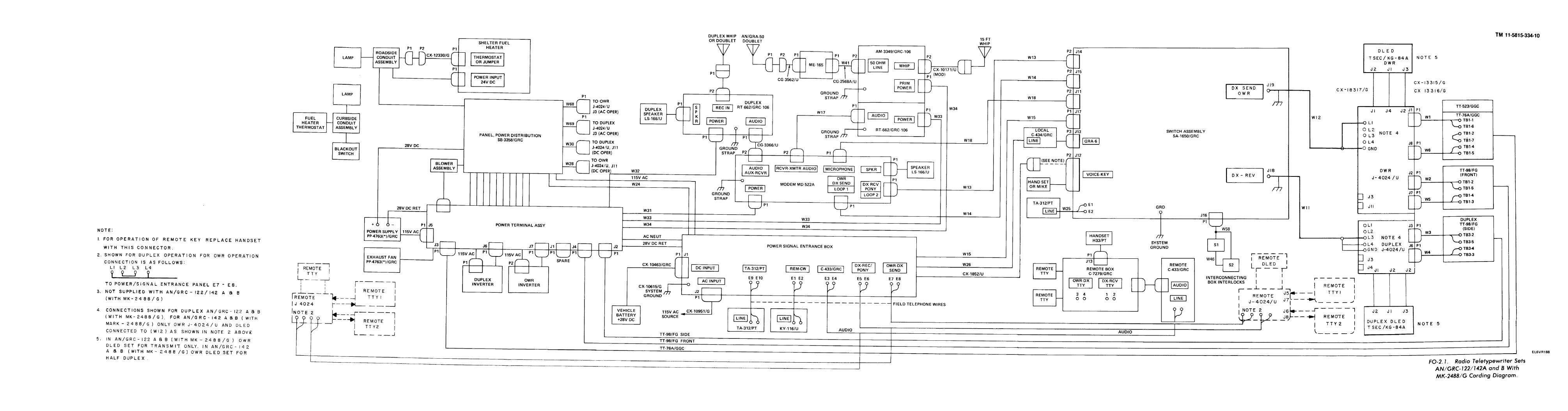
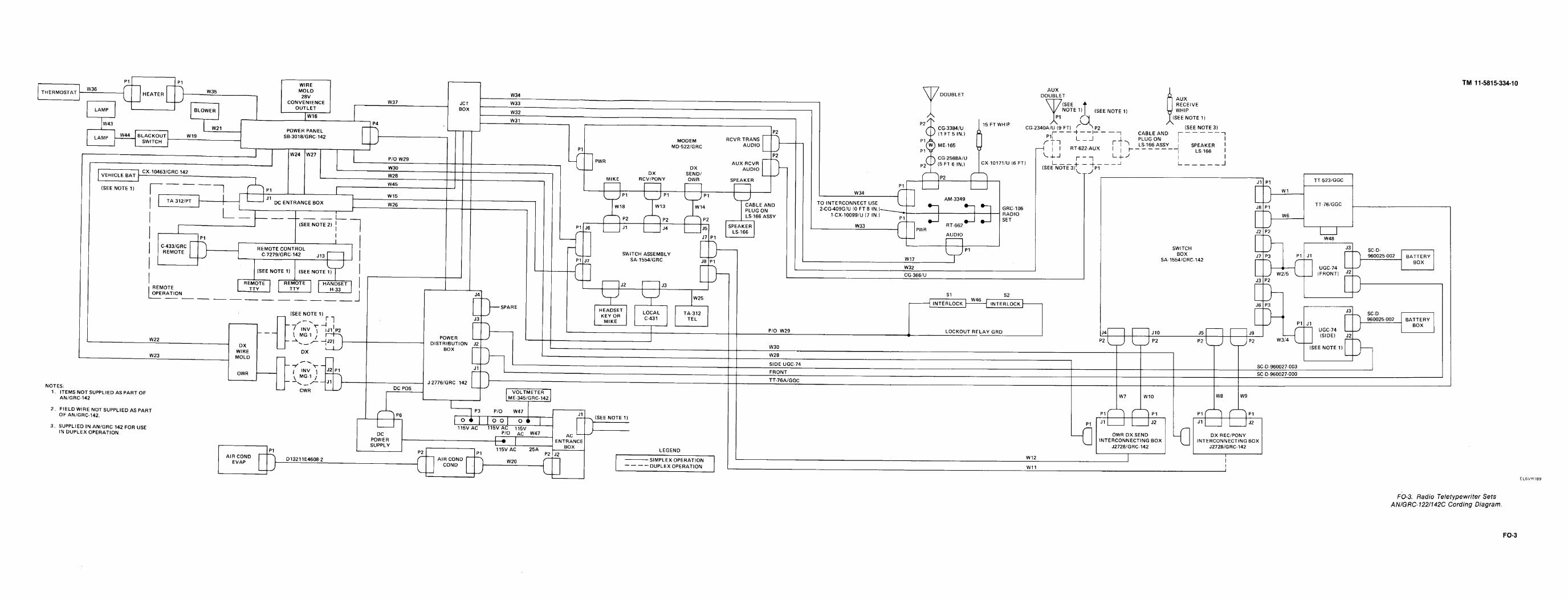
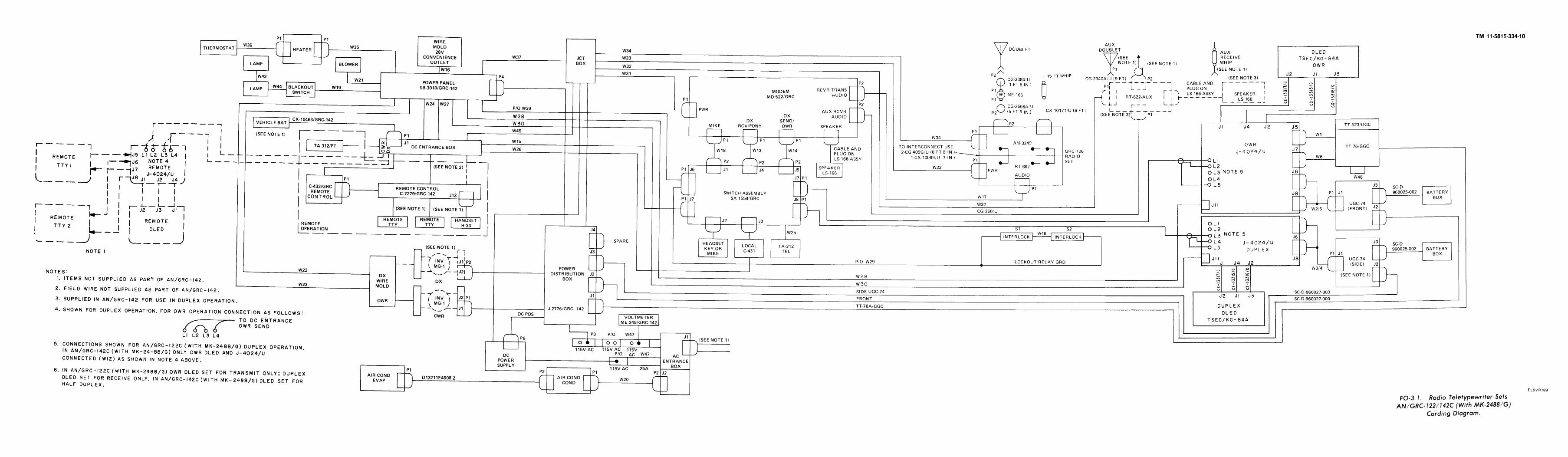
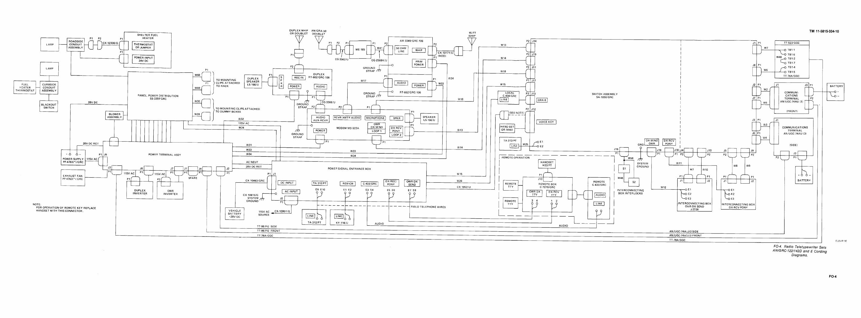

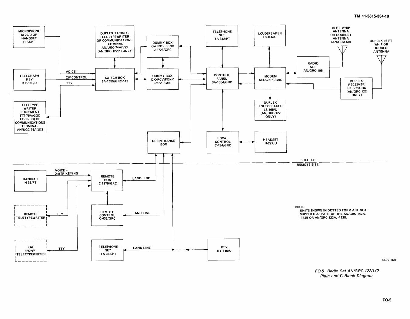
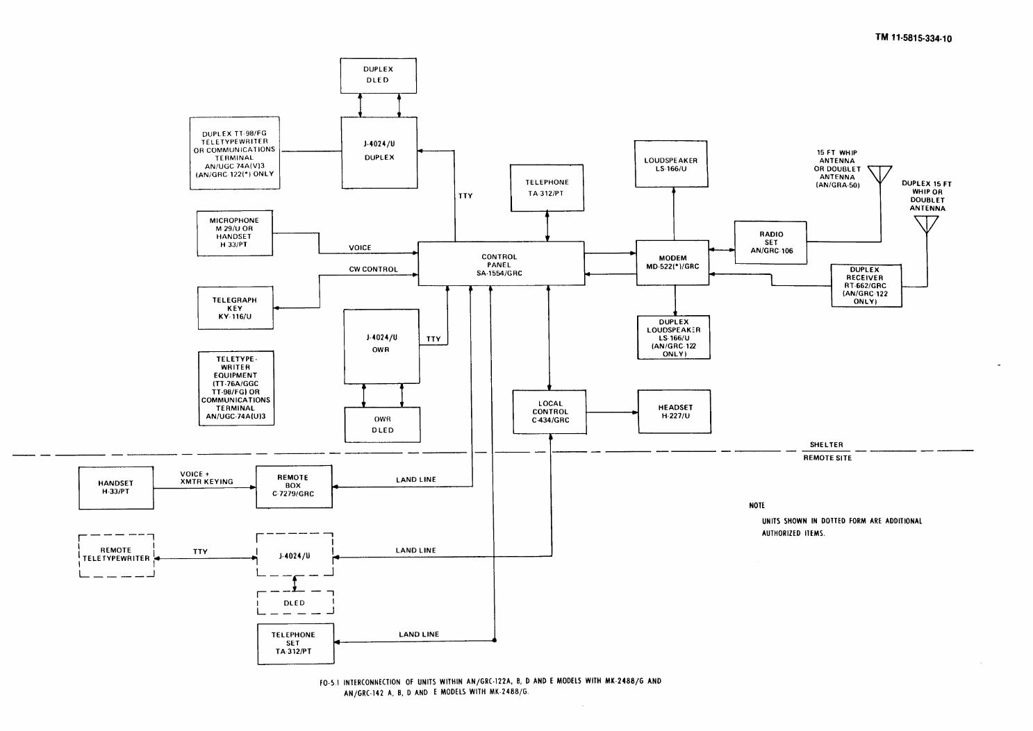
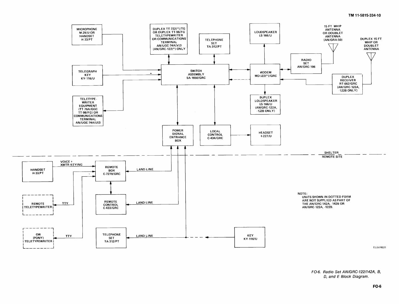
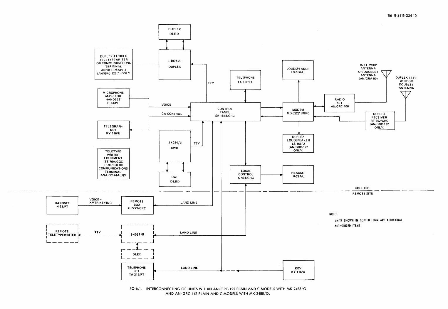

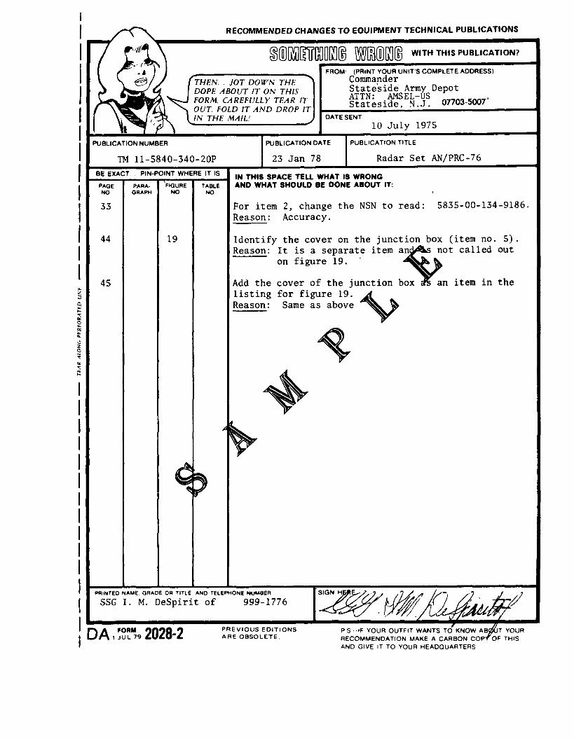
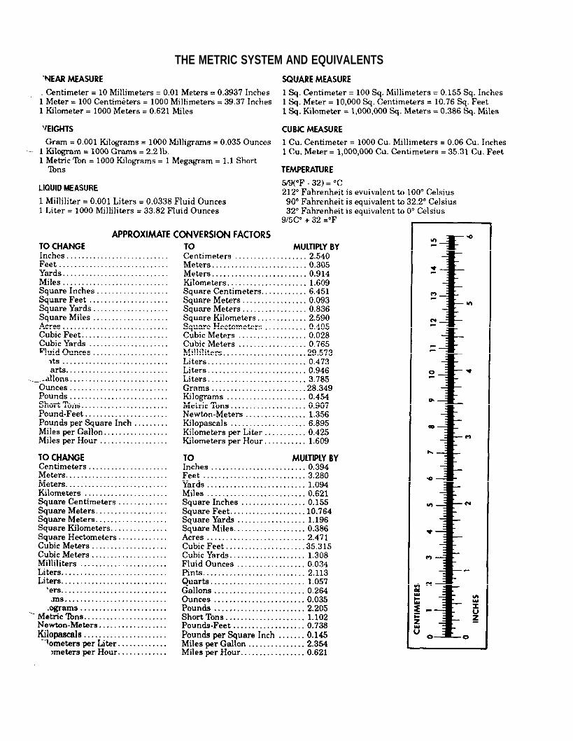


![Bill's Ham Radio Web Server [nj7p.info/nj7p.org] - OPERATOR ... 11-5815-332-15 15...RADIO TELETYPEWRITER SET AN/VSC-3A (NSN 5815-01-102-5916) TM 11-5815-332-15, 14 January 1971, is](https://static.documents.pub/doc/80x56/611e2198dbfb4036d0587b04/bills-ham-radio-web-server-nj7pinfonj7porg-operator-11-5815-332-15-15.jpg)


