TM 55-1945-219-14&P TECHNICAL MANUAL OPERATOR, UNIT, DIRECT SUPPORT AND GENERAL SUPPORT MAINTENANCE MANUAL (INCLUDING REPAIR PARTS AND SPECIAL TOOLS LIST) FOR INCINOLET (RESEARCH PRODUCTS) MODEL # WB NSN 4510-01-470-8101 DISTRIBUTION STATEMENT A - Approved for public release; distribution is unlimited. HEADQUARTERS, DEPARTMENT OF THE ARMY JUNE 2004
Transcript
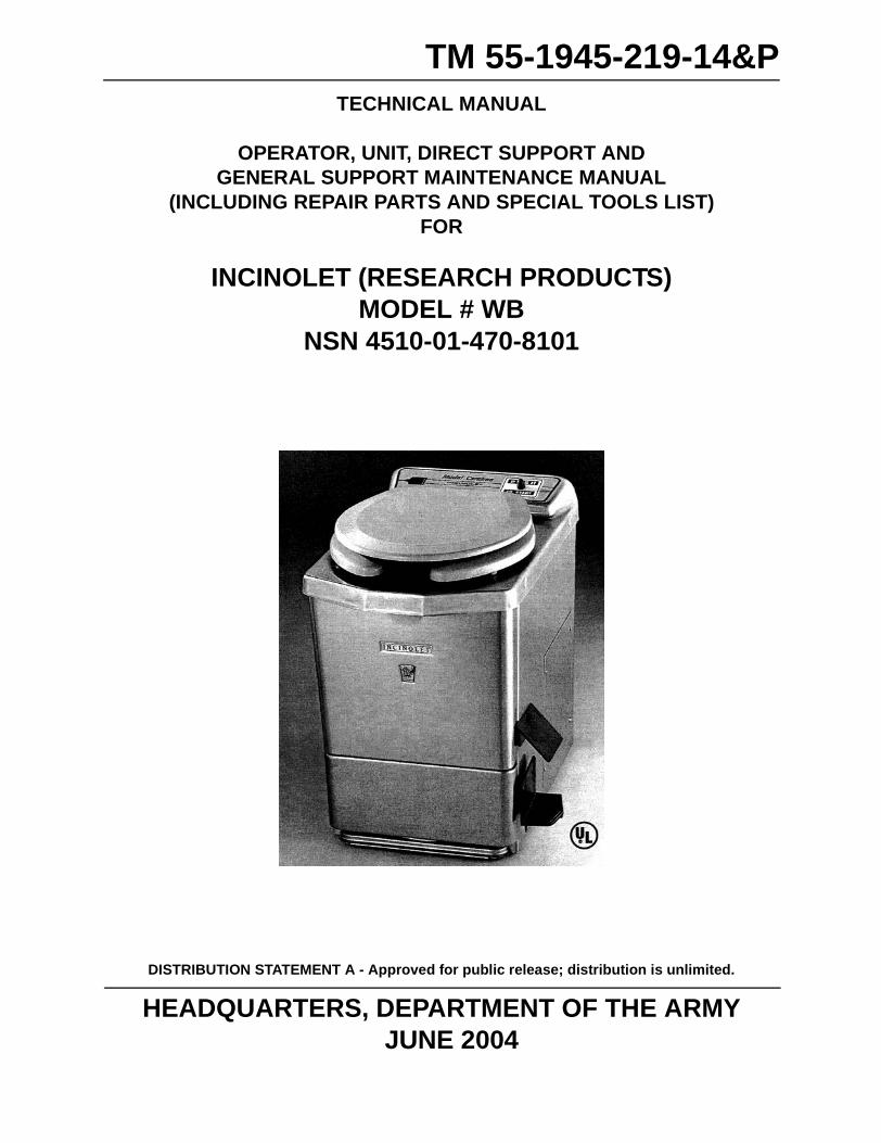
TM 55-1945-219-14&PTECHNICAL MANUAL
OPERATOR, UNIT, DIRECT SUPPORT AND GENERAL SUPPORT MAINTENANCE MANUAL
(INCLUDING REPAIR PARTS AND SPECIAL TOOLS LIST)FOR
INCINOLET (RESEARCH PRODUCTS)MODEL # WB
NSN 4510-01-470-8101
DISTRIBUTION STATEMENT A - Approved for public release; distribution is unlimited.
HEADQUARTERS, DEPARTMENT OF THE ARMYJUNE 2004
TM 55-1945-219-14&P
LIST OF EFFECTIVE PAGES
Dates of issue for original and changed pages are:
Original ....0 .....1 JUNE 2004
TOTAL NUMBER OF PAGES FOR FRONT AND REAR MATTER IS 20 AND TOTAL NUMBER OF PAGES IN CHAPTERS ARE 34 CONSISTING OF THE FOLLOWING:
The following pages do not apply to the Incinolet toilet installed on the Modular Causeway System (MCS).
B
TM 55-1945-219-14&P
INDENTIFYING TECHNICAL PUBLICATION SHEETFOR
INCINOLET (RESEARCH PRODUCTS)
1. PURPOSE: This technical publication is issued to identify and authorize the following commercial manual for Army use.
MANUFACTURER: Research Products, 2639 Andjon, Dallas, TX 75220; CAGEC (23989)PURCHASE ORDER OR CONTRACT NUMBER: DAAE 07-01-D-T026REQUISITION NUMBER: N/AEQUIPMENT: Incinerator Toilet, Model WBNATIONAL STOCK NUMBER: 4510-01-470-8101TITLE: Operator, Unit, Direct Support and General Support Maintenance Manual (Including Repair Parts & Special Tools List)ADDITIONAL IDENTIFICATION: NoneDATE: 1 July 2002
2. ADDITIONAL COPIES: Additional copies are available from the US Army Publishing Agency.
3. FILE LOCATION: The above described commercial manual is filed in ______________________________. (Each library will fill this in if this identifying technical publication sheet is filed separately from the commercial manual.)
4. AUTHORITY NOTICE AND DISTRIBUTION STATEMENT: Published Under Authority of the Secretary of the Army. Distribution Statement A - Approved for public release; distribution is unlimited.
SUPPLEMENTAL DATA
1. LIST OF AFFECTED PAGES IN BASIC MANUAL. This list will identify supplemental pages by number, and date thereon that have been deleted and added by incorporating supplemental data. This page will also identify information not applicable to the equipment used on the Modular Causeway System (MCS).
2. SUPPLEMENTARY INFORMATION. The information contained in the above identified commercial manual is supplemented as follows:
a. Identifying Technical Publication Sheet.b. Front Manual Cover.c. Title Block Page.d. List of Effective Pages.e. Table of Contents.f. Chapter Identification Pages.g. Maintenance Allocation Chart (MAC) Introduction.h. Maintenance Allocation Chart (MAC).i. Maintenance Allocation Chart (MAC) Remarks.j. Repair Parts List.k. DA Form 2028.l. Metric Conversion Chart.
TM 55-1945-219-14&P
HEADQUARTERSDEPARTMENT OF THE ARMY
WASHINGTON, D.C. 1 JUNE 2004
TECHNICAL MANUAL
OPERATOR, UNIT, DIRECT SUPPORT AND GENERAL SUPPORT MAINTENANCE MANUAL
FOR
INCINOLET (RESEARCH PRODUCTS)MODEL # WB
NSN 4510-01-470-8101
DISTRIBUTION STATEMENT A - Approved for public release; distribution is unlimited.
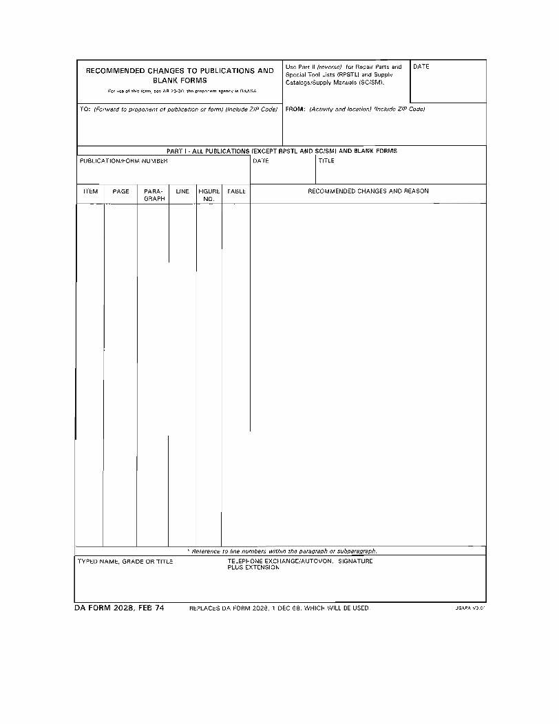
REPORTING ERRORS AND RECOMMENDING IMPROVEMENTS
You can help improve this publication. If you find any mistakes or if you know of a way to improve theprocedures, please let us know. Submit your DA Form 2028 (Recommended Changes to EquipmentTechnical Publications), through the Internet, on the Army Electronic Product Support (AEPS) website.The Internet address is http://aeps.ria.army.mil. If you need a password, scroll down and click on“ACCESS REQUEST FORM”. The DA Form 2028 is located in the ONLINE FORMS PROCESSINGsection of the AEPS. Fill out the form and click on SUBMIT. Using this form on the AEPS will enable us torespond quicker to your comments and better manage the DA Form 2028 program. You may also mail,fax or email your letter or DA Form 2028 direct to: AMSTA-LC-CI / TECH PUBS, TACOM-RI, 1 RockIsland Arsenal, Rock Island, IL 61299-7630. The email address is [email protected] fax number is DSN 793-0726 or Commercial (309) 782-0726.
TM 55-1945-219-14&P
i
TABLE OF CONTENTS
Chapter No/Page No.
PUBLICATION SHEET
INCINOLET (RESEARCH PRODUCTS) COVER PAGE
List of Effective Pages ................................................................................................................. AERRATA Page ............................................................................................................................ B
TITLE PAGE
Table Of Contents ........................................................................................................................ i
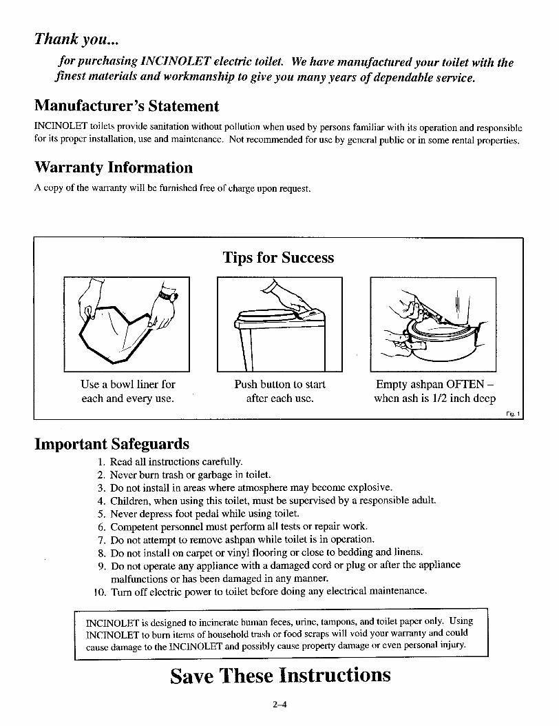
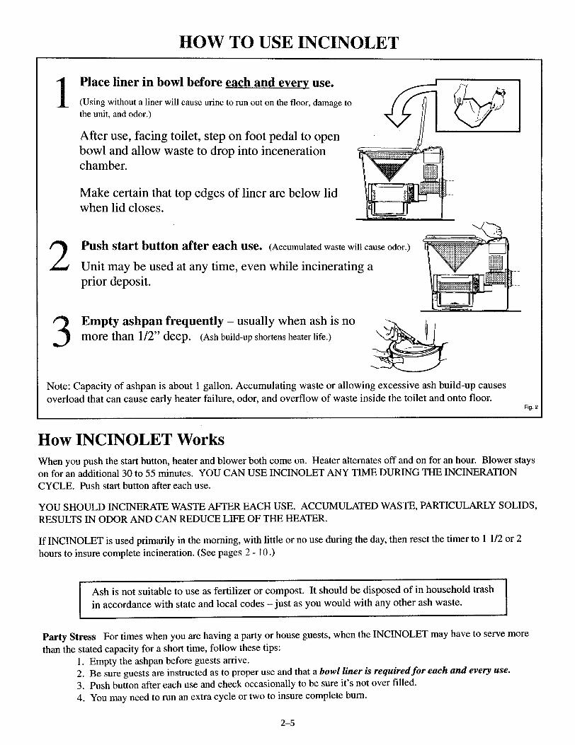
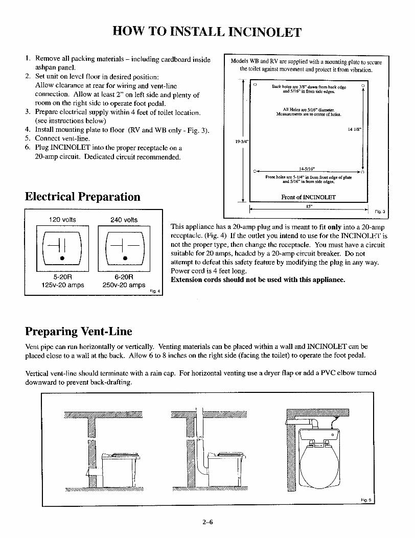
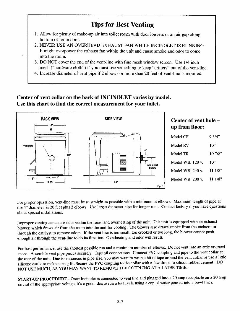
Installation/Maintenance Manual ................................................................................................ 2–03Manufacturer’s Statement ........................................................................................................... 2–04Warranty Information .................................................................................................................. 2–04Important Safeguards ................................................................................................................... 2–04How To Use INCINOLET .......................................................................................................... 2–05How INCINOLET Works ........................................................................................................... 2–05How To Install INCINOLET ....................................................................................................... 2–06Electrical Preparation .................................................................................................................. 2–06Preparing Vent-Line .................................................................................................................... 2–06Understanding Electrical Operation ............................................................................................ 2–08
Power Consumption ...................................................................................................... 2–08During A Power Failure ................................................................................................ 2–08Interrupt An Incineration Cycle .................................................................................... 2–08Thermostats ................................................................................................................... 2–08Care And Cleaning ........................................................................................................ 2–09Bowl Liners ................................................................................................................... 2–09How To Remove Ash Pan ............................................................................................. 2–09Removing The Top ....................................................................................................... 2–09Access Panel ................................................................................................................. 2–09
Troubleshooting Procedures ........................................................................................................ 2–10Timer Adjustment ......................................................................................................... 2–10Blower Comes On But Heater Does Not Heat .............................................................. 2–10Timer Light Works But Controller Red Light Is Not On ............................................. 2–10Circuit Breaker Opens When Start Button Is Pushed ................................................... 2–10Nothing Comes On, But Timer Green Light Is On ....................................................... 2–10Blower, Heater Will Not Stay On ................................................................................. 2–10Blower Stops At End Of Heating Cycle ....................................................................... 2–10Blower Does Not Operate ............................................................................................. 2–10Blower Off And On At Cycle End ................................................................................ 2–10Bowl Hangs Open: Pedal Won’t Return ....................................................................... 2–10Excessive Noise And Vibration .................................................................................... 2–10Incomplete Incineration ................................................................................................ 2–10
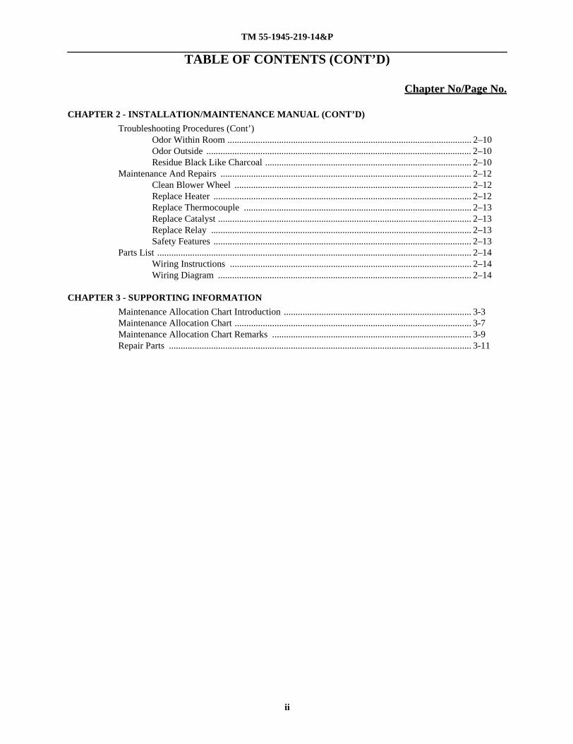
Troubleshooting Procedures (Cont’)Odor Within Room ........................................................................................................ 2–10Odor Outside ................................................................................................................. 2–10Residue Black Like Charcoal ........................................................................................ 2–10
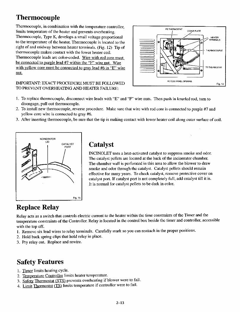
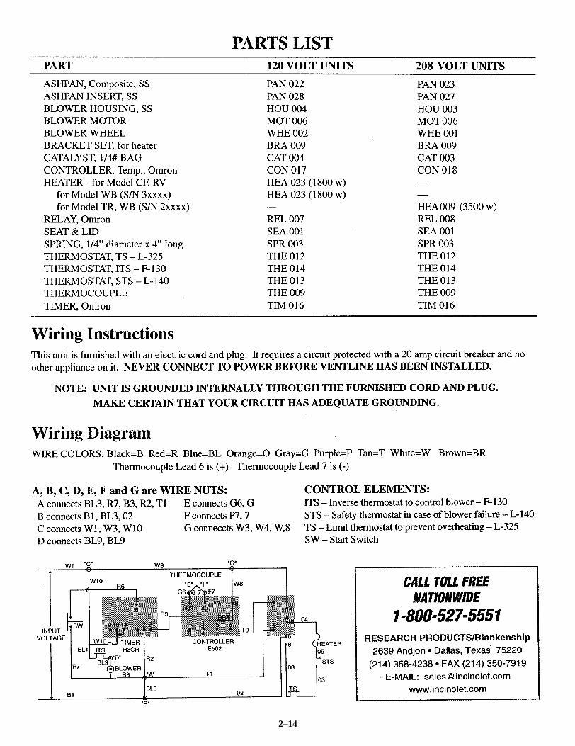
Parts List ...................................................................................................................................... 2–14Wiring Instructions ....................................................................................................... 2–14Wiring Diagram ............................................................................................................ 2–14
OPERATOR, UNIT, DIRECT SUPPORT AND GENERAL SUPPORTINCINOLET (RESEARCH PRODUCTS)
MAINTENANCE ALLOCATION CHART (MAC) INTRODUCTION
INTRODUCTION
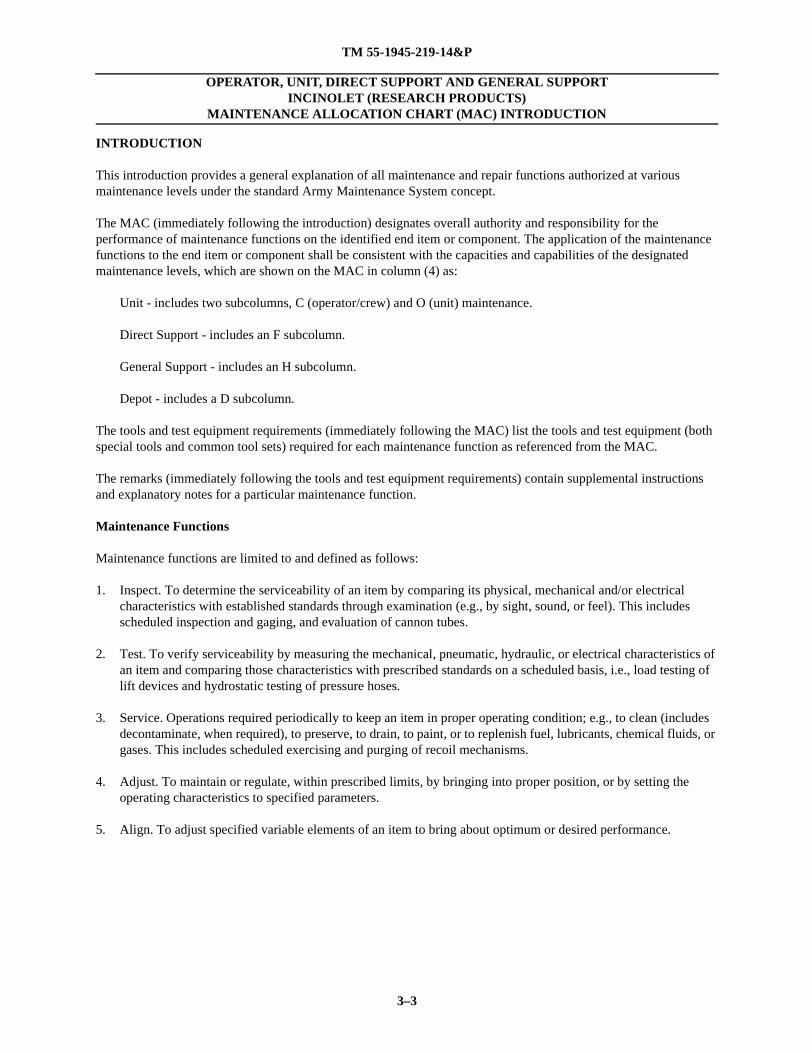
This introduction provides a general explanation of all maintenance and repair functions authorized at various maintenance levels under the standard Army Maintenance System concept.
The MAC (immediately following the introduction) designates overall authority and responsibility for the performance of maintenance functions on the identified end item or component. The application of the maintenance functions to the end item or component shall be consistent with the capacities and capabilities of the designated maintenance levels, which are shown on the MAC in column (4) as:
Unit - includes two subcolumns, C (operator/crew) and O (unit) maintenance.
Direct Support - includes an F subcolumn.
General Support - includes an H subcolumn.
Depot - includes a D subcolumn.
The tools and test equipment requirements (immediately following the MAC) list the tools and test equipment (both special tools and common tool sets) required for each maintenance function as referenced from the MAC.
The remarks (immediately following the tools and test equipment requirements) contain supplemental instructions and explanatory notes for a particular maintenance function.
Maintenance Functions
Maintenance functions are limited to and defined as follows:
1. Inspect. To determine the serviceability of an item by comparing its physical, mechanical and/or electrical characteristics with established standards through examination (e.g., by sight, sound, or feel). This includes scheduled inspection and gaging, and evaluation of cannon tubes.
2. Test. To verify serviceability by measuring the mechanical, pneumatic, hydraulic, or electrical characteristics of an item and comparing those characteristics with prescribed standards on a scheduled basis, i.e., load testing of lift devices and hydrostatic testing of pressure hoses.
3. Service. Operations required periodically to keep an item in proper operating condition; e.g., to clean (includes decontaminate, when required), to preserve, to drain, to paint, or to replenish fuel, lubricants, chemical fluids, or gases. This includes scheduled exercising and purging of recoil mechanisms.
4. Adjust. To maintain or regulate, within prescribed limits, by bringing into proper position, or by setting the operating characteristics to specified parameters.
5. Align. To adjust specified variable elements of an item to bring about optimum or desired performance.
COTS TM 55-1945-219-14&P
3–4
6. Calibrate. To determine and cause corrections to be made or to be adjusted on instruments or test, measuring, and diagnostic equipment used in precision measurement. Consists of comparisons of two instruments, one of which is a certified standard of known accuracy, to detect and adjust any discrepancy in the accuracy of the instrument being compared.
7. Remove/Install. To remove and install the same item when required to perform service or other maintenance functions. Install may be the act of emplacing, seating, or fixing into position a spare, repair part, or module (component or assembly) in a manner to allow the proper functioning of an equipment or system.
8. Replace. To remove an unserviceable item and install a serviceable counterpart in its place. “Replace” is authorized by the MAC and assigned maintenance level is shown as the third position code of the Source, Maintenance and Recoverabilty (SMR) code.
9. Repair. The application of the maintenance services, including fault location/troubleshooting, removal/installation, disassembly/assembly procedures, and maintenance actions to identify troubles and restore serviceability to an item by correcting specific damage, fault, malfunction, or failure in a part, subassembly, module (component or assembly), end item, or system.
NOTEThe following definitions are applicable to the “repair” maintenance function:
Fault location/troubleshooting — The process of investigating and detecting the cause of equipment malfunctioning; the act of isolating a fault within a system or Unit
Under Test (UUT).
Disassembly/assembly — The step-by-step breakdown (taking apart) of a spare/functional group coded item to the level of its least component, that is assigned an SMR code for the
level of maintenance under consideration (i.e., identified as maintenance significant).
10. Overhaul. That maintenance effort (service/action) prescribed to restore an item to a completely serviceable/operational condition as required by maintenance standards in appropriate technical publications. Overhaul is normally the highest degree of maintenance performed by the Army. Overhaul does not normally return an item to like new condition.
11. Rebuild. Consists of those services/actions necessary for the restoration of unserviceable equipment to a like new condition in accordance with original manufacturing standards. Rebuild is the highest degree of maintenance applied to Army equipment. The rebuild operation includes the act of returning to zero those age measurements (e.g., hours/miles) considered in classifying Army equipment/components.
Explanation of Columns in the MAC
Column (1) — Group Number. Column (1) lists FGC numbers, the purpose of which is to identify maintenance significant components, assemblies, subassemblies, and modules with the Next Higher Assembly (NHA).
Column (2) — Component/Assembly. Column (2) contains the item names of components, assemblies, subassemblies, and modules for which maintenance is authorized.
Column (3) — Maintenance Function. Column (3) lists the functions to be performed on the item listed in column (2). (For a detailed explanation of these functions refer to “Maintenance Functions” outlined above.)
TM 55-1945-219-14&P
3–5
Column (4) — Maintenance Level. Column (4) specifies each level of maintenance authorized to perform each function listed in column (3), by indicating work time required (expressed as man-hours in whole hours or decimals) in the appropriate subcolumn. This work time figure represents the active time required to perform that maintenance function at the indicated level of maintenance. If the number or complexity of the tasks within the listed maintenance function varies at different maintenance levels, appropriate work time figures are to be shown for each level. The work time figure represents the average time required to restore an item (assembly, subassembly, component, module, end item, or system) to a serviceable condition under typical field operating conditions. This time includes preparation time (including any necessary disassembly/assembly time), troubleshooting/fault location time, and quality assurance time in addition to the time required to perform the specific tasks identified for the maintenance functions authorized in the MAC. The symbol designations for the various maintenance levels are as follows:
C — Operator or crew maintenance
O — Unit maintenance
F — Direct support maintenance
L — Specialized repair activity (SRA)
H — General support maintenance
D — Depot maintenance
NOTEThe “L” maintenance level is not included in column (4) of the MAC. Functions to this level of maintenance are identified by a work time figure in the “H” column of column (4), and an associated reference code is used in the REMARKS column (6). This code is keyed to the
remarks and the SRA complete repair application is explained there.
Column (5) — Tools and Equipment Reference Code. Column (5) specifies, by code, those common tool sets (not individual tools), common Test, Measurement and Diagnostic Equipment (TMDE), and special tools, special TMDE and special support equipment required to perform the designated function. Codes are keyed to the entries in the tools and test equipment table.
Column (6) — Remarks Code. When applicable, this column contains a letter code, in alphabetical order, which is keyed to the remarks table entries.
Explanation of Columns in the Tools and Test Equipment Requirements
Column (1) — Tool or Test Equipment Reference Code. The tool or test equipment reference code correlates with a code used in column (5) of the MAC.
Column (2) — Maintenance Level. The lowest level of maintenance authorized to use the tool or test equipment.
Column (3) — Nomenclature. Name or identification of the tool or test equipment.
Column (4) — National Stock Number (NSN). The NSN of the tool or test equipment.
Column (5) — Tool Number. The manufacturer’s part number, model number, or type number.
COTS TM 55-1945-219-14&P
3–6
Explanation of the Columns in the Remarks
Column (1) — Remarks Code. The code recorded in column (6) of the MAC.
Column (2) — Remarks. This column lists information pertinent to the maintenance function being performed as indicated in the MAC.
TM 55-1945-219-14&P
3–7/3–8 blank
OPERATOR, UNIT, DIRECT SUPPORT AND GENERAL SUPPORT INCINOLET (RESEARCH PRODUCTS)
MAINTENANCE ALLOCATION CHART (MAC)
MAINTENANCE ALLOCATION CHART
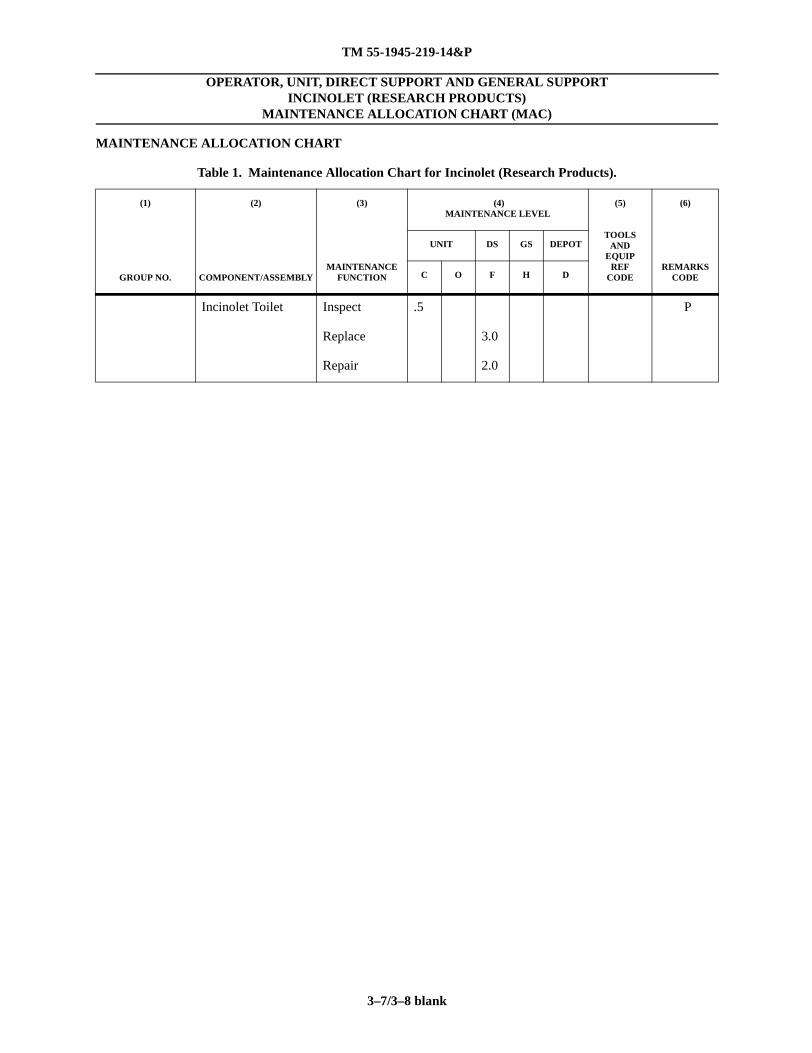
Table 1. Maintenance Allocation Chart for Incinolet (Research Products).
(1)
GROUP NO.
(2)
COMPONENT/ASSEMBLY
(3)
MAINTENANCEFUNCTION
(4)MAINTENANCE LEVEL
(5)
TOOLSAND
EQUIPREF
CODE
(6)
REMARKS CODE
UNIT DS GS DEPOT
C O F H D
Incinolet Toilet Inspect .5 P
Replace 3.0
Repair 2.0
TM 55-1945-219-14&P
3–9/3–10 blank
OPERATOR, UNIT, DIRECT SUPPORT AND GENERAL SUPPORT INCINOLET (RESEARCH PRODUCTS)
MAINTENANCE ALLOCATION CHART (MAC)
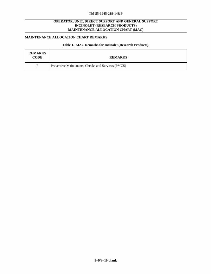
MAINTENANCE ALLOCATION CHART REMARKS
Table 1. MAC Remarks for Incinolet (Research Products).
REMARKS CODE REMARKS
P Preventive Maintenance Checks and Services (PMCS)
TM 55-1945-219-14&P
3–11/3–12 blank
OPERATOR, UNIT, DIRECT SUPPORT AND GENERAL SUPPORT INCINOLET (RESEARCH PRODUCTS)
REPAIR PARTS
(1)ITEMNO.
(3)
NSN
(4)
CAGEC
(5)PARTNUMBER
(6)DESCRIPTION ANDUSABLE ON CODE (UOC)
(7)
QTY
1 23989 PAN 023 Ashpan, Composite, SS
2 23989 PAN 027 Ashpan, Insert, SS
3 23989 HOU 003 Blower, Housing, SS
4 23989 MOT 006 Blower Motor
5 23989 WHE001 Blower Wheel
6 23989 BRA 009 Bracket Set, for Heater
7 23989 CAT 003 Catalyst, ¼# BAG
8 23989 CON018 Controller, Temp, Omron
9 23989 ---- Heater (CF & RV)
10 23989 ---- Heater (WB)
11 23989 HEA 009 (3500 W) Heater (TR & WB)
12 4510-01-470-9561 23989 LIN 001 Liner BX/200
13 23989 REL 008 Relay, Omron
14 23989 SEA 001 Seat & Lid
15 23989 SPR 003 Spring, ¼ in. Diameter X 4 in. long
16 23989 THE 012 Thermostat, TS - L-325
17 23989 THE 014 Thermostat, ITS - L-130
18 23989 THE 013 Thermostat, STS - L-140
19 23989 THE 009 Thermocouple
20 23989 TIM 016 Timer, Omron
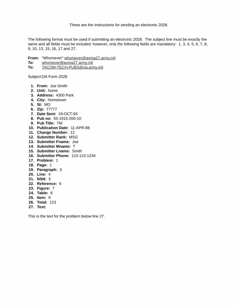
These are the instructions for sending an electronic 2028.
The following format must be used if submitting an electronic 2028. The subject line must be exactly the same and all fields must be included; however, only the following fields are mandatory: 1, 3, 4, 5, 6, 7, 8, 9, 10, 13, 15, 16, 17 and 27.
Liberated Manuals -- free army and government manuals
Why do I do it? I am tired of sleazy CD-ROM sellers, who take publicly available information, slap “watermarks” and other junk on it, and sell it. Those masters of search engine manipulation make sure that their sites that sell free information, come up first in search engines. They did not create it... They did not even scan it... Why should they get your money? Why are not letting you give those free manuals to your friends?
I am setting this document FREE. This document was made by the US Government and is NOT protected by Copyright. Feel free to share, republish, sell and so on.
I am not asking you for donations, fees or handouts. If you can, please provide a link to liberatedmanuals.com, so that free manuals come up first in search engines:
<A HREF=http://www.liberatedmanuals.com/>Free Military and Government Manuals</A>


![Hannah v Peel (1945) - [1945] K.B. 509](https://static.documents.pub/doc/80x56/544f9c22b1af9f11098b460a/hannah-v-peel-1945-1945-kb-509.jpg)


