MELiSSA TECHNICAL NOTE 87.2.11 This document is confidential property of the MELiSSA partners and shall not be used, duplicated, modified or transmitted without their authorization Memorandum of Understanding 19071/05/NL/CP 1 TECHNICAL NOTE 87.2.11 CIVa refurbishment detailed design Prepared by/Préparé par Mangas, F. and Mestre, J. (DeDietrich Equipos Químicos, S.L.) Reference/Réference MELiSSA Pilot Plant Frame Contract 19445/05/NL/CP Issue/Edition 0 Revision/Révision 0 Date of issue/Date d’édition 31/07/08 Status/Statut Final
Transcript
MELiSSA TECHNICAL NOTE 87.2.11
This document is confidential property of the MELiSSA partners and shall not be used, duplicated, modified or transmitted without their authorization
- General 3D layout, DD-8506-Z1-102-01, Rev. C - Alternative Lay out (option D) - Alternative Lay out (option E) - P&ID Diagram. DD-8506-Z1-100-01. Rev. L
- P&ID Diagram: Control Loop. DD-8506-Z1-100-02. Rev. B
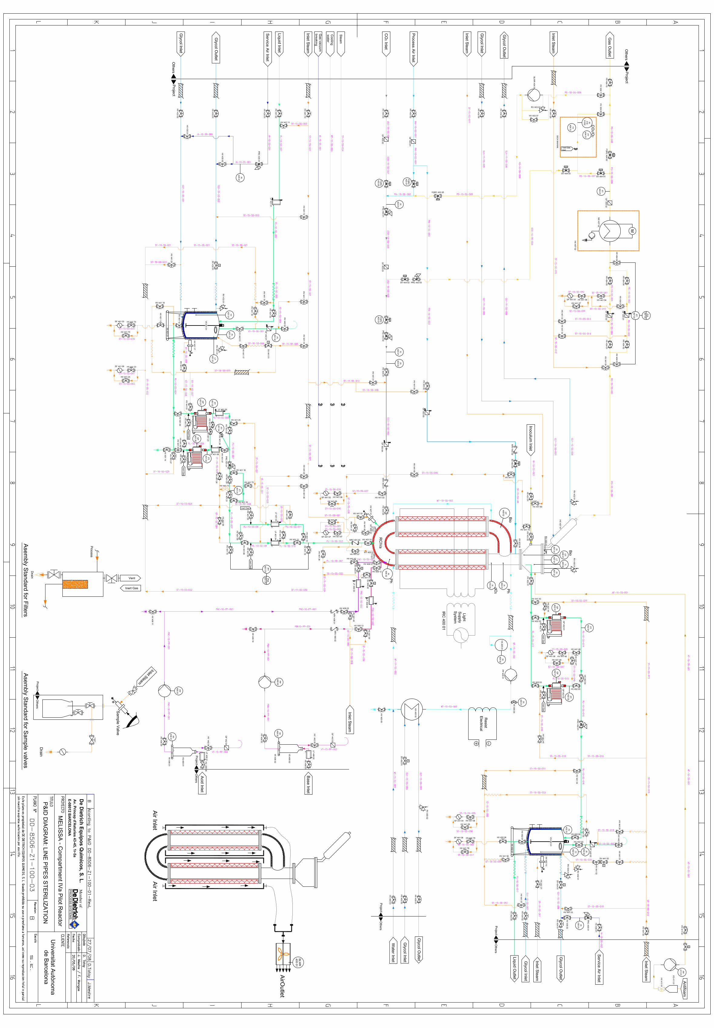
- P&ID Diagram: Line pipes sterilization. DD-8506-Z1-100-03. Rev. B - P&ID Diagram: Vacuum breaking. DD-8506-Z1-100-04. Rev. A
CODE PROJECT: DD-8506-Z1 Rev. E CUSTOMER: UAB PROJECT: MELISSA COMPARMENT IVa DATE: 06/05/2008
PREPARED: F.M.P.
PÁG 19 de 25
Ref. PRK-005257
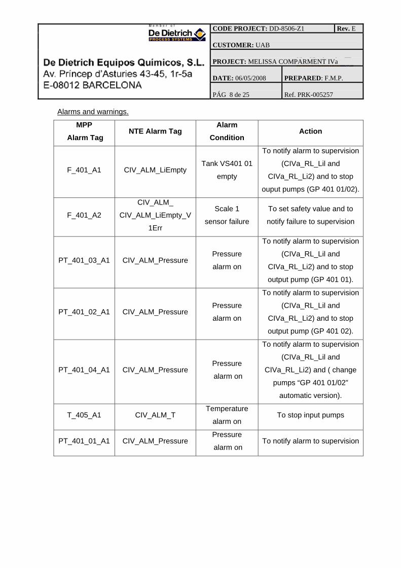
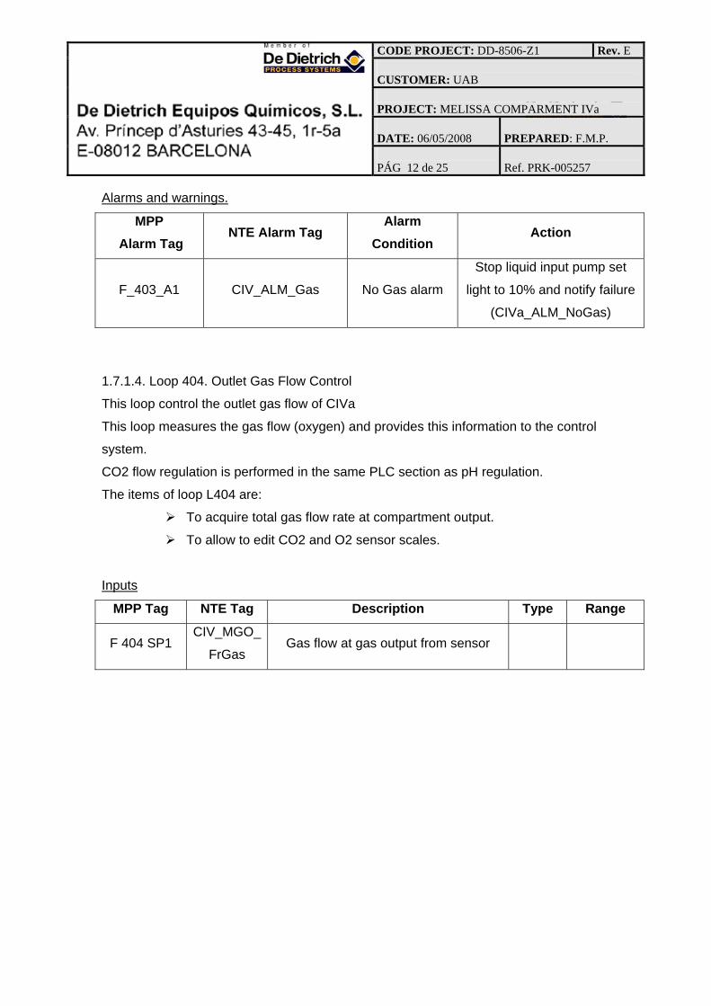
Alarms and warnings.
MPP Alarm Tag
NTE Alarm Tag Alarm Condition Action
P_407_01_A1 CIV_ALM_PHH
Alarm to notify
pressure sensor
high pressure
inside of reacotr
Notify failure and to stop inlet
gas
P_407_01_A2 CIV_ALM_PErr
Alarm to notify
pressure sensor
link error
Set safety value (nominal
setpoint) and notify failure
P_407_02_A1 CIV_ALM_PHH
Alarm to notify
pressure sensor
high pressure
inside of reacotr
Notify failure and to stop inlet
gas
P_407_02_A2 CIV_ALM_PErr
Alarm to notify
pressure sensor
link error
Set safety value (nominal
setpoint) and notify failure
CODE PROJECT: DD-8506-Z1 Rev. E CUSTOMER: UAB PROJECT: MELISSA COMPARMENT IVa DATE: 06/05/2008
PREPARED: F.M.P.
PÁG 20 de 25
Ref. PRK-005257
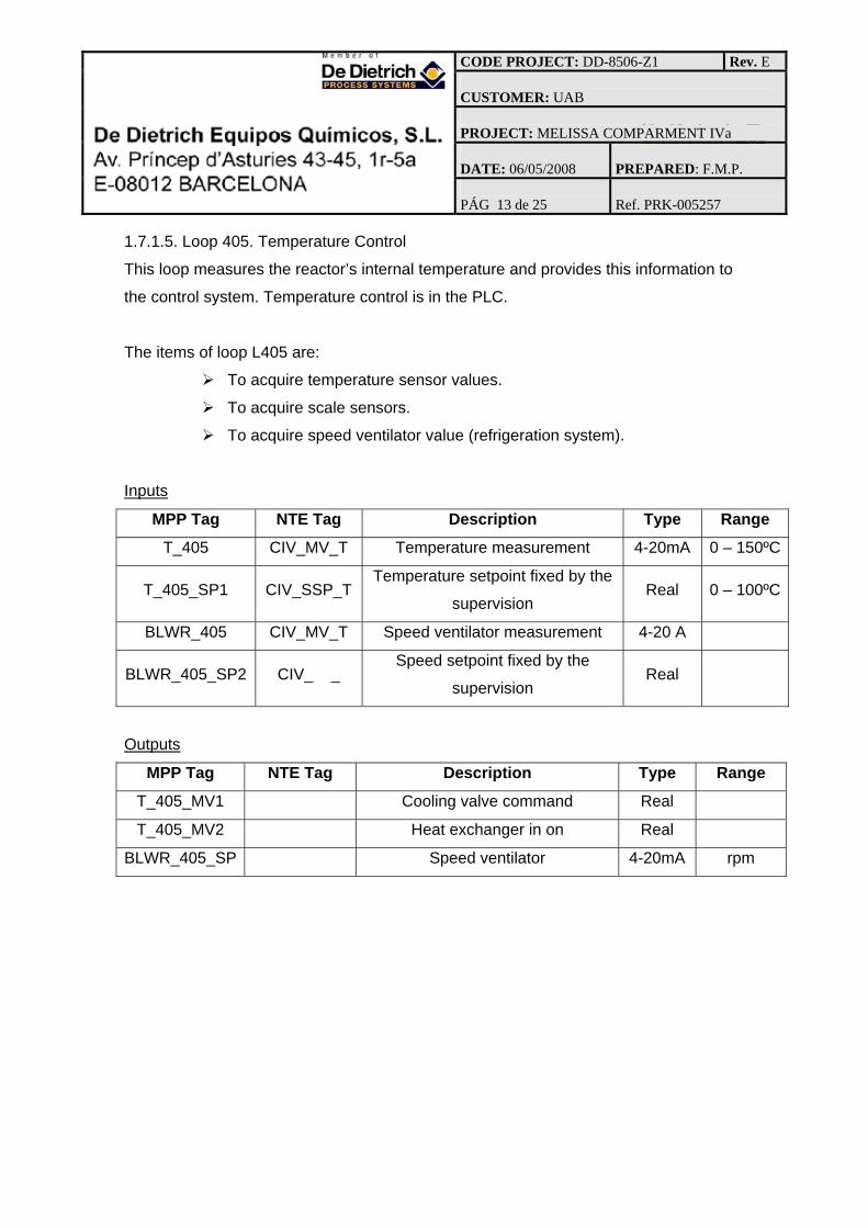
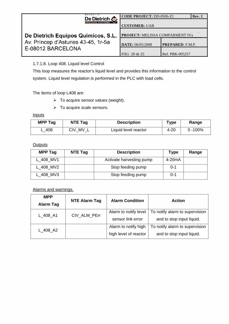
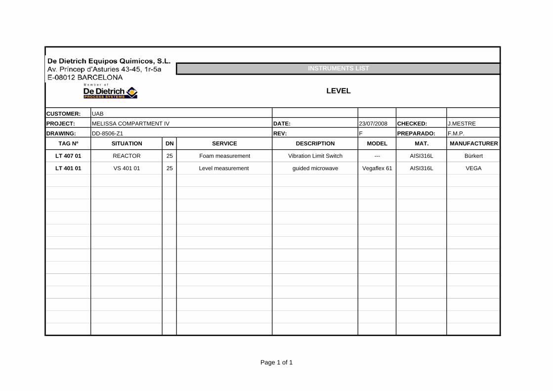
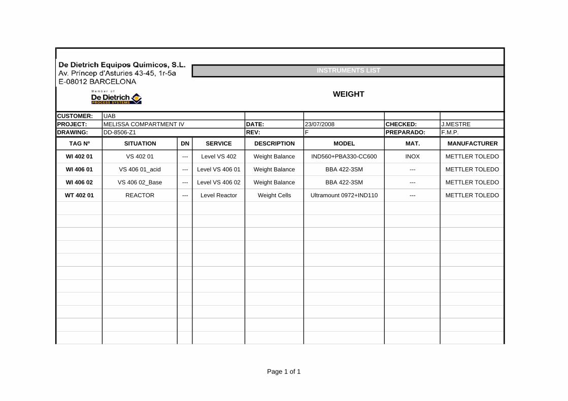
1.7.1.8. Loop 408. Liquid level Control
This loop measures the reactor’s liquid level and provides this information to the control
system. Liquid level regulation is performed in the PLC with load cells.
The items of loop L408 are:
To acquire sensor values (weight).
To acquire scale sensors.
Inputs
MPP Tag NTE Tag Description Type Range
L_408 CIV_MV_L Liquid level reactor 4-20 0 -100%
Outputs
MPP Tag NTE Tag Description Type Range
L_408_MV1 Activate harvesting pump 4-20mA
L_408_MV2 Stop feeding pump 0-1
L_408_MV3 Stop feeding pump 0-1
Alarms and warnings.
MPP Alarm Tag
NTE Alarm Tag Alarm Condition Action
L_408_A1 CIV_ALM_PErr Alarm to notify level
sensor link error
To notify alarm to supervision
and to stop input liquid.
L_408_A2 Alarm to notify high
high level of reactor
To notify alarm to supervision
and to stop input liquid.
CODE PROJECT: DD-8506-Z1 Rev. E CUSTOMER: UAB PROJECT: MELISSA COMPARMENT IVa DATE: 06/05/2008
PREPARED: F.M.P.
PÁG 21 de 25
Ref. PRK-005257
1.7.1.9. Loop 409. Biomass Control
This loop measures the reactor’s biomass concentration and provides this information
to the control system.
Biomass production loop is controlled by an external program to the controller. It mixes
the liquid flow control and the light intensity control.
Biomass concentration acquisition is performed in light attenuation units, to provide
biomass concentration in dry weight units (g/l) a conditioning set of the value is
performed.
In addition the section includes biomass sensor cleaning logic.
The items of loop F409 are:
To acquire the biomass concentration (two sensors).
To clean the biomass sensor a pulse is generated every 5 minutes
during 5 seconds to open the compressed air valves.
To maintain the biomass input value held since the valve is opened to 5
seconds after the valve is closed to avoid disturbances while the sensor
is being cleaned.
To calculate actual biomass production: Biomass production = liquid
input flow * Biomass concentration (dw)
To adjust inlet and outlet liquid flows
Inputs
MPP Tag NTE Tag Description Type Range
Bio_409_01 CIV_MV_CxAb
s_01
Biomass concentration in
absorvance unit 4-20mA Configurable
Bio_409_02 CIV_MV_CxAb
s_02
Biomass concentration in
absorvance unit 4-20mA Configurable
Bio_409_SP1 Biomass production setpoint
Bio_409_SP2 Biomass production setpoint
CODE PROJECT: DD-8506-Z1 Rev. E CUSTOMER: UAB PROJECT: MELISSA COMPARMENT IVa DATE: 06/05/2008
PREPARED: F.M.P.
PÁG 22 de 25
Ref. PRK-005257
Outputs
MPP Tag NTE Tag Description Type Range
I_400_SP CIV_SSP_LIBP Light intensity setpoint Real 0 –10g/h
F_401_SP1 Liquid pump input 01 setpoint
from supervision Real
F_401_SP2 Liquid pump input 02 setpoint
from supervision Real
Alarms and warnings.
MPP Alarm Tag
NTE Alarm Tag Alarm Condition Action
Bio_409_A1 CIV_ALM_CxErr01 Biomass sensor
failure
Set safety value (1,0) and
notify failure
Bio_409_A2 CIV_ALM_CxErr02 Biomass sensor
failure
Set safety value (1,0) and
notify failure
CODE PROJECT: DD-8506-Z1 Rev. E CUSTOMER: UAB PROJECT: MELISSA COMPARMENT IVa DATE: 06/05/2008
PREPARED: F.M.P.
PÁG 23 de 25
Ref. PRK-005257
1.7.1.10. Loop 410. Outlet Gas Composition Control
This loop composition gas control is not implemented.
1.7.1.11. Loop 441. Automatic sterilization
This control is not implemented.
1.7.1.12. Loop 412. Antifoam Control (Potential implementation)
This loop detects the presence of foam and provides this information to the control
system.
Antifoam flow regulation is performed in the PLC with switch level sensor (vibronic).
The items of loop F412 are:
To acquire the presence of foam (limit level of foam in reactor).
Inputs
MPP Tag NTE Tag Description Type Range
LVL_412_01 Detection of foam
measurement 0/1
Outputs
MPP Tag NTE Tag Description Type Range
LVL_412_SP
Active pump antifoam + open
automatic valve inlet liquid of
antifoam
Alarms and warnings.
MPP Alarm Tag
NTE Alarm Tag Alarm Condition Action
LVL_412_A1 Vibronic sensor
failure To notify alarm to supervision
LVL_412_A2 Antifoam pump link
error To notify error to supervision
CODE PROJECT: DD-8506-Z1 Rev. E CUSTOMER: UAB PROJECT: MELISSA COMPARMENT IVa DATE: 06/05/2008
PREPARED: F.M.P.
PÁG 24 de 25
Ref. PRK-005257
1.7.1.13. Loop 432. Temperature Control inside of feeding tank
This loop measures the feeding tank’s internal temperature and provides this
information to the control system. Temperature control is in the PLC.
The items of loop L432 are:
To acquire temperature sensor values.
To acquire scale sensors.
Inputs
MPP Tag NTE Tag Description Type Range
TT_401 01 Temperature measurement 4-20mA 0 – 150ºC
TT_432_SP1 Temperature setpoint fixed by the
supervision Real 0 – 150ºC
Outputs
MPP Tag NTE Tag Description Type Range
SV 432 01 Cooling valve command Real
SV 441 01 Heat valve command Real
Alarms and warnings.
MPP Alarm Tag
NTE Alarm Tag Alarm Condition Action
TT_401_A1 Temperature
sensor failure
To set a safety value
(temperature setpoint) and
notify failure
SV_441 01_A1 Automatic Valve
failure To notify failure
SV_432 01 Automatic Valve
failure To notify failure
CODE PROJECT: DD-8506-Z1 Rev. E CUSTOMER: UAB PROJECT: MELISSA COMPARMENT IVa DATE: 06/05/2008
PREPARED: F.M.P.
PÁG 25 de 25
Ref. PRK-005257
1.7.1.13. Loop 434. Temperature Control inside of harvesting tank
This loop measures the harvesting tank’s internal temperature and provides this
information to the control system. Temperature control is in the PLC.
The items of loop L434 are:
To acquire temperature sensor values.
To acquire scale sensors.
Inputs
MPP Tag NTE Tag Description Type Range
TT_402 01 Temperature measurement 4-20mA 0 – 150ºC
TT_434_SP1 Temperature setpoint fixed by the
supervision Real 0 – 150ºC
Outputs
MPP Tag NTE Tag Description Type Range
SV 434 01 Cooling valve command Real
SV 441 02 Heat valve command Real
Alarms and warnings.
MPP Alarm Tag
NTE Alarm Tag Alarm Condition Action
TT_402_A1 Temperature
sensor failure
To set a safety value
(temperature setpoint) and
notify failure
SV_441 02_A1 Automatic Valve
failure To notify failure
SV_432 02 Automatic Valve
failure To notify failure
MELiSSA TECHNICAL NOTE 87.2.11
This document is confidential property of the MELiSSA partners and shall not be used, duplicated, modified or transmitted without their authorization
Memorandum of Understanding 19071/05/NL/CP 35
3. CALCULATIONS
2008
Author: Francisco Mangas Company: De Dietrich Equipos Químicos Date: 28/07/2008
[CALCULATIONS]
CODE PROJECT: DD-8506-Z1 Rev. B CUSTOMER: UAB PROJECT: MELISSA COMPARMENT IVa DATE: 02/06/2008
PREPARED: F.M.P.
PÁG 2 de 11
Ref. PRK-005257
Página 2
DROP PRESSURE: LOOP OF REFRIGERATION OF BIOREACTOR
Parameters Lengths of pipe including bioreactor ”jacket”: 5 meters. Pipe DN15 Number of bend 90º = 10 Number of bend 45º = 5 Number through Tee = 4 Number of valves = 2
Flow cool water = 1 m3/h Temperature = 15 ºC The calculation has been realized using the following program “Pipe Flow Expert”. Results. ΔΡ = 0.5 barg Flow type: Turbulent
CODE PROJECT: DD-8506-Z1 Rev. B CUSTOMER: UAB PROJECT: MELISSA COMPARMENT IVa DATE: 02/06/2008
PREPARED: F.M.P.
PÁG 3 de 11
Ref. PRK-005257
Página 3
DROP PRESSURE: OUTLET GAS OF THE BIOREACTOR
Parameters Lengths of pipe: 3 meters. Pipe DN10 Number of bend 90º = 4 Number of bend 45º = 2 Number through Tee = 10 Number of valves = 6
Flow Air = 0.21 l/min Temperature = 20 ºC The calculation has been realized using the following program “Pipe Flow Expert”. Results. ΔΡ = 0.0 barg Flow type: laminar
CODE PROJECT: DD-8506-Z1 Rev. B CUSTOMER: UAB PROJECT: MELISSA COMPARMENT IVa DATE: 02/06/2008
PREPARED: F.M.P.
PÁG 4 de 11
Ref. PRK-005257
Página 4
DROP PRESSURE: PROCESS GAS INSIDE OF THE BIOREACTOR
Parameters Height liquid inside of bioreactor = 2 meter Density of medium = 1000 kg/m3 Equation: Pressure bottom of bioreactor =Density x Height
Results. ΔΡ = 0.2 barg
CODE PROJECT: DD-8506-Z1 Rev. B CUSTOMER: UAB PROJECT: MELISSA COMPARMENT IVa DATE: 02/06/2008
PREPARED: F.M.P.
PÁG 5 de 11
Ref. PRK-005257
Página 5
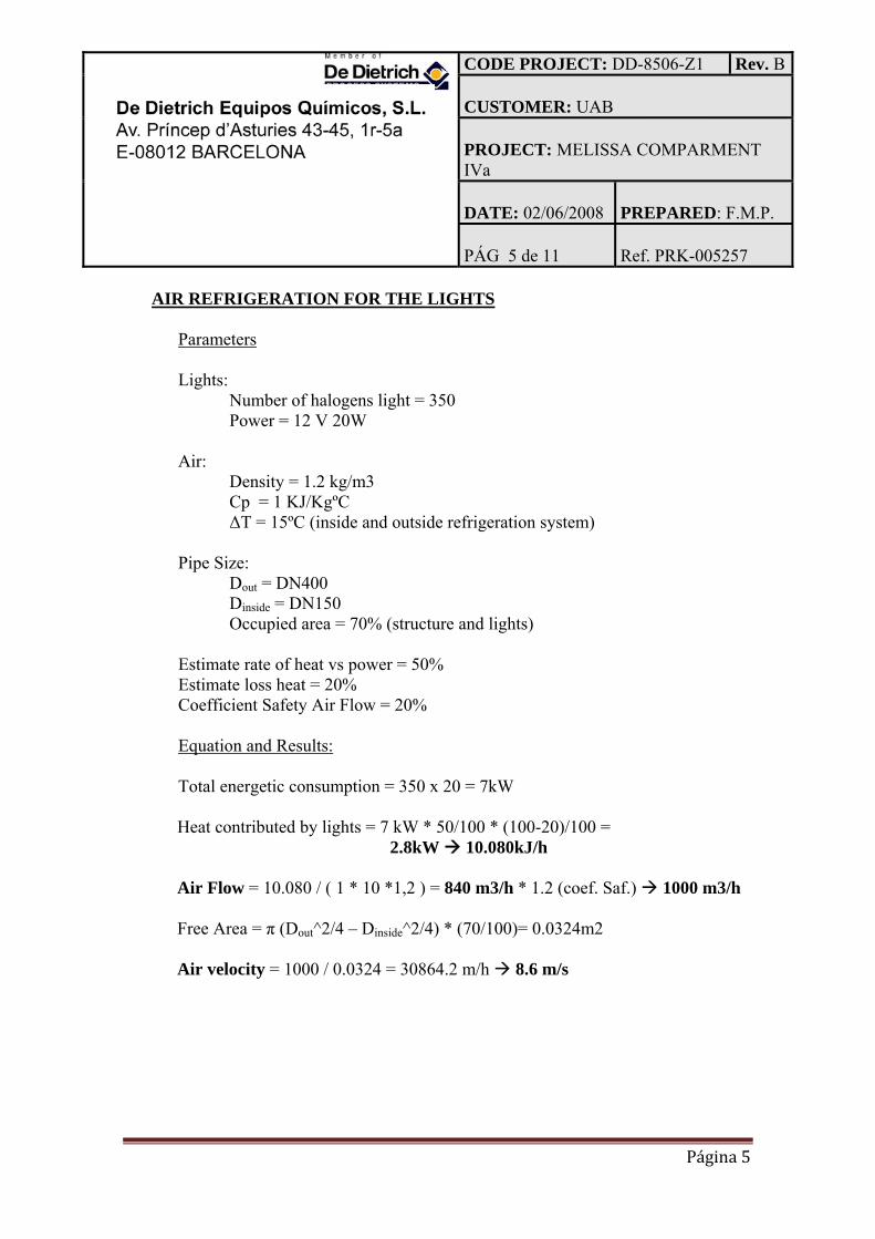
AIR REFRIGERATION FOR THE LIGHTS
Parameters Lights:
Number of halogens light = 350 Power = 12 V 20W Air:
Density = 1.2 kg/m3 Cp = 1 KJ/KgºC
ΔT = 15ºC (inside and outside refrigeration system) Pipe Size:
Dout = DN400 Dinside = DN150
Occupied area = 70% (structure and lights) Estimate rate of heat vs power = 50% Estimate loss heat = 20% Coefficient Safety Air Flow = 20% Equation and Results: Total energetic consumption = 350 x 20 = 7kW
ΔTcool water = 10.080/(4,18 x 103) = 2.5 ºC Transfer energy q= UAΔTm. ΔTm= 2409.18/(400*0.3) = 20ºC ATmavailable = ((35-15) – (35-20))/ln((35-15)/(35/20)) 17ºC
CODE PROJECT: DD-8506-Z1 Rev. B CUSTOMER: UAB PROJECT: MELISSA COMPARMENT IVa DATE: 02/06/2008
PREPARED: F.M.P.
PÁG 7 de 11
Ref. PRK-005257
Página 7
Sterilization Time Heating Nomenclature V: Design criterion for sterilization. N0: Number of viable spores initially presents N: Number of viable spores T: Sterilization temperature K: Specific reaction rate for thermal spore destruction. h: Enthalpy of steam relative to raw medium temperature s: Steam mass flow rate. Cp: Heat Capacity of Bioreactor medium U: Over-all heat transfer coefficient A: Area of Bioreactor Tco: Temperature of cooling water Type spore: Bacillus Sterothermophilus Parameter value: N0: 5.6 x 10¹² spores N: 10-6 spores T: 120ºC V: ln(5.6 x 10¹²/10-6) = 43.17
Cycle: Heating
Parameters
Empty Bioreactor (Air)
Alfa h (kJ/kg) 2250 S (kg/min) 0,33 M (kg) 80 Cp(kJ/Kg ºC) 1 To (K) 298 U(kcal/m2minºK) 400 Área (m2) 0,24 Tco (K) 288 T (K) 394
CODE PROJECT: DD-8506-Z1 Rev. B CUSTOMER: UAB PROJECT: MELISSA COMPARMENT IVa DATE: 02/06/2008
Time heating to arrived sterilization temperature = 52 minutes
CODE PROJECT: DD-8506-Z1 Rev. B CUSTOMER: UAB PROJECT: MELISSA COMPARMENT IVa DATE: 02/06/2008
PREPARED: F.M.P.
PÁG 10 de 11
Ref. PRK-005257
Página 10
Cycle: Heating constant temperature 120ºC (sterilization temperature)
Parameters Bioreactor witch Medium
Alfa K (120ºC)s‐1 0.015
Time of Sterilization = 43.17/0.015 48 min Note: In the cycle of heating/cooling (20ºC to 120ºC/ 120 to 20ºC) there’re sterilization but these values of sterilization are used how factor of safety.
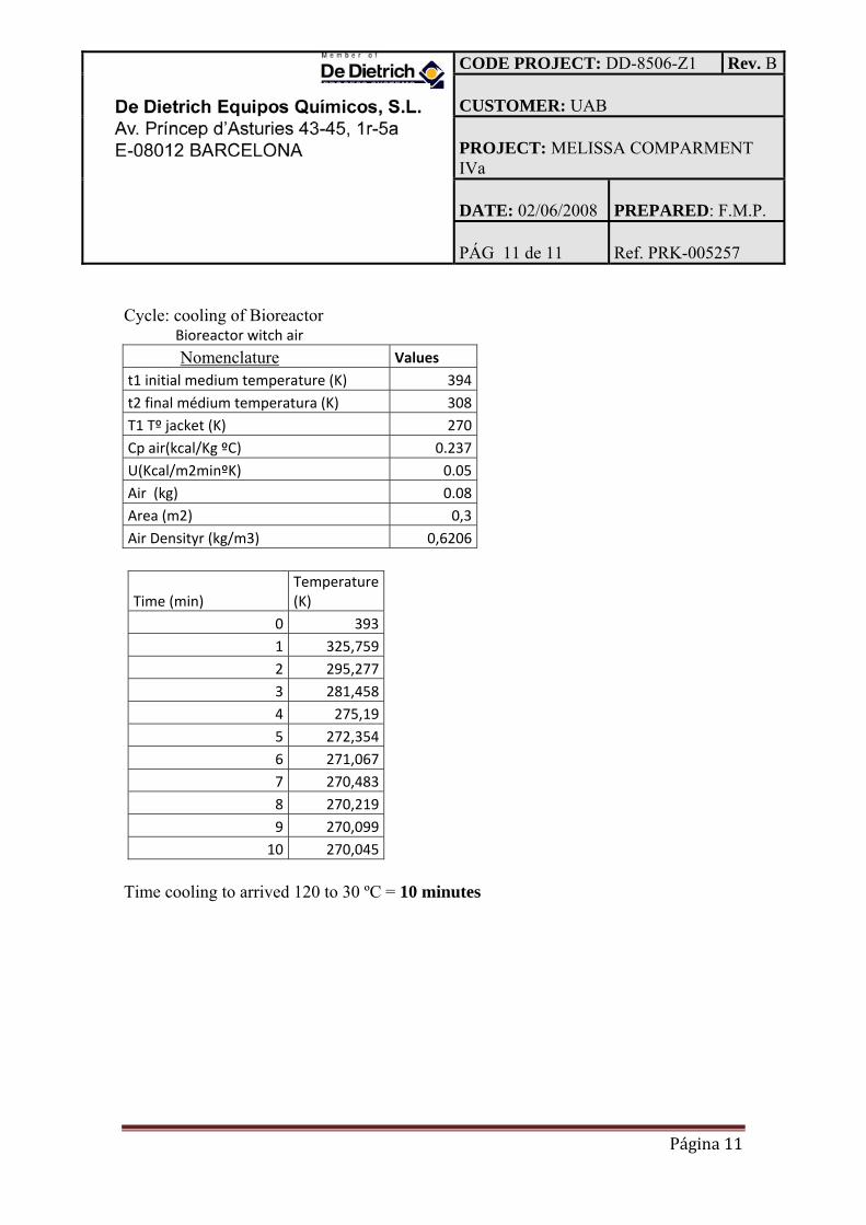
Cycle: cooling of Bioreactor
Bioreactor witch medium Nomenclature Values
t1 initial medium temperature (K) 394t2 final médium temperatura (K) 308T1 Tº jacket (K) 270Cp(kcal/Kg ºC) 1U(Kcal/m2minºK) 7M (kg) 80Area (m2) 0,3
This document is confidential property of the MELiSSA partners and shall not be used, duplicated, modified or transmitted without their authorization
Memorandum of Understanding 19071/05/NL/CP 47
4. GENERAL DESCRIPTION: SEQUENCES
2008
Author: Francisco Mangas Company: De Dietrich Equipos Químicos Date: 21/05/2008
[GENERAL DESCRIPTION: SEQUENCES]
CODE PROJECT: DD-8506-Z1 Rev. B CUSTOMER: UAB PROJECT: MELISSA COMPARMENT IVa DATE: 02/06/2008
PREPARED: F.M.P.
PÁG 2 de 7
Ref. PRK-005257
Página 2
GENERAL DESCRIPTION SEQUENCES: LIST 1. Filling Sequences
a. Filling feeding Tank Sequence b. Filling Harvesting Tank Sequence c. Filling Bioreactor Sequence d. Filling Vessel Acid e. Filling Vessel Basic f. Filling cooling water refrigeration Bioreactor Sequence
2. Empting Sequences
a. Empting feeding Tank Sequence b. Empting Harvesting Tank Sequence c. Empting Bioreactor Sequence d. Empting Vessel Acid Sequence e. Empting Vessel Basic Sequence f. Empting cooling water refrigeration Bioreactor Sequence g. Empting process pipe Sequence
3. Start pumps Sequences
a. Filling of the bioreactor b. Emptying of the bioreactor
4. Sterilization Sequences: list
a. Empty feeding Tank Sterilization Sequence b. Empty harvesting Tank Sterilization Sequence c. Empty Sterilization Sequence of Liquid Inlet Filter F-401 01 d. Empty Sterilization Sequence of Gas Vent Filter GF-442 01 e. Empty Sterilization Sequence of Sample valve HV-401 17 f. Empty Sterilization Sequence of Pump GP-401 01 and Liquid filter LF-
401 05 g. Empty Sterilization Sequence of Pump GP-401 02 and Liquid filter LF-
401 06 h. Empty Sterilization Sequence of Liquid Inlet Filter LF-401 03 i. Empty Sterilization Sequence of Liquid Inlet Filter LF-401 04 j. Empty Sterilization Sequence of Gas Inlet Filter GF-403 04 k. Empty Sterilization Sequence of Sample valve HV-407 01 l. Empty Sterilization Sequence of Liquid Inlet filter LF-406 03 m. Empty Sterilization Sequence of Liquid Inlet filter LF-406 04 n. Empty Sterilization Reactor Sequence o. Empty Sterilization Sequence of Gas Outlet filter GF-404 01
CODE PROJECT: DD-8506-Z1 Rev. B CUSTOMER: UAB PROJECT: MELISSA COMPARMENT IVa DATE: 02/06/2008
PREPARED: F.M.P.
PÁG 3 de 7
Ref. PRK-005257
Página 3
p. Empty Sterilization Sequence of Gas inlet filter GF-403 05 q. Empty Sterilization Sequence of Gas Outlet filter GF-404 02 r. Empty Sterilization Sequence of Pump GP-402 01 s. Empty Sterilization Sequence of Pump GP-402 02 t. Empty Sterilization Sequence of Sample valve HV-402 10 u. Empty Sterilization Sequence of Gas Vent Filter GF-442 02 v. Empty Sterilization Sequence of line pipe PL-10-SS-002/003 w. Empty Sterilization Sequence of line pipe PL-10-SS-004 x. Empty Sterilization Sequence of line pipe PL-10-SS-007 y. Empty Sterilization Sequence of line pipe PL-10-SS-012 z. Empty Sterilization Sequence of line pipe PL-10-SS-016 aa. Empty Sterilization Sequence of line pipe PL-10-SS-013 bb. Empty Sterilization Sequence of line pipe PG-10-SS-001 cc. Empty Sterilization Sequence of mass flowmeter FT 401 01 dd. Empty Sterilization Sequence of Biomass sensors OT 409 01 and OT
409 02 ee. Empty Sterilization Sequence of Temperature sensor TI 405 01 ff. Empty Sterilization Sequence of Pressure sensors PI 407 01 and PI 407
02 gg. Empty Sterilization Sequence of Level sensor LT 407 01 hh. Empty Sterilization Sequence of pH sensors AI 406 01 and AI 406 02 ii. Empty Sterilization Sequence of Dissolved Oxigen sensors AI 410 03 jj. Empty Sterilization Sequence of inoculums system kk. Sequence “Fill feeding Tank with medio” ll. Sequence “Fill Photo Bioreactor with media” mm. Sequence “Fill Harvesting Tank with media”
CODE PROJECT: DD-8506-Z1 Rev. B CUSTOMER: UAB PROJECT: MELISSA COMPARMENT IVa DATE: 02/06/2008
PREPARED: F.M.P.
PÁG 4 de 7
Ref. PRK-005257
Página 4
1a.-General Description of Filling Sequence The sequences of Filling are used when for process reasons they are needed. The Filling and Empting are manuals sequences; Operator operates directly in the manual valves. Steps of Sequence The sequence is started by an operator. See below the steps: Step 1: Vent Equipment
- To check correct utilities (Instrument) - Open valves in the outlet air (vent pipe)
Step 2: Equipment
- To check that the valve of outlet liquid of the equipment is closed Step 3: Inlet liquid of the Equipment
- To open the valves of inlet liquid Step 4: Ending of the Sequence
- To close the valves of entry of the equipment
CODE PROJECT: DD-8506-Z1 Rev. B CUSTOMER: UAB PROJECT: MELISSA COMPARMENT IVa DATE: 02/06/2008
PREPARED: F.M.P.
PÁG 5 de 7
Ref. PRK-005257
Página 5
2.-General Description of Empty Sequence The sequences of empty are used when for process reasons they are needed. The Empting are manuals sequences; Operator operates directly in the manual valves. Steps of Sequence The sequence is started by operator. See below the steps: Step 1: Vent Equipment To check for correct utilities (Instrument)
- Open valves in the outlet air (vent pipe) Step 2: Equipment
- To check that the valve of inlet liquid of the equipment is closed Step 3: Inlet liquid of the Equipment
- To open the valves (drain valve) of inlet liquid Step 4: Ending of the Sequence
- To close the valves of outlet of the equipment
CODE PROJECT: DD-8506-Z1 Rev. B CUSTOMER: UAB PROJECT: MELISSA COMPARMENT IVa DATE: 02/06/2008
PREPARED: F.M.P.
PÁG 6 de 7
Ref. PRK-005257
Página 6
3.- Start up pumps Sequence : General Description The sequences of start up pumps are used when for process reasons they are needed. The start up pumps ( Filling and Empting) to Bioreactor are automatic sequences; The operator defines a set point and the system of control takes charge supporting the above mentioned set point. Steps of Sequence The sequence is started by a operator. See below the steps: Step 1: Check general of instalation
- To check correct utilities (Instrument) - To check don’t exist lack in the installation
Step 2: Manual operation by operator
- To check that the valve are in correct position.
Step 3: Start up the pumps
- To enable the loop of pumps system control by the operator.
CODE PROJECT: DD-8506-Z1 Rev. B CUSTOMER: UAB PROJECT: MELISSA COMPARMENT IVa DATE: 02/06/2008
PREPARED: F.M.P.
PÁG 7 de 7
Ref. PRK-005257
Página 7
4.General Description of Sterilization Sequence The sequence is used to sterilize by direct steam injection into the pipe. The sterilization is a manual sequence; Operator operates directly in the manual valves. The sequence is controlled by a Timer, so that each step of the sequence has a fixed duration. Steps of Sequence The sequence is started by a operator, the steps as description below: Step 1: Sterilization step To check for correct utilities (Instrument and Clean Steam)
- Heat up 10 min. to sterilization temperature. - Further heating 45 min. to sterilize.
If the sterilization is completed, Step 1 is finished. Step 2: Cooling step Cool down the filter and/or pump and pipes for 30 min. Cool down by convection cooling. Vacuum breaking via:
Inlet Process Air: Reactor, Harvesting Tank and line pipe outlet liquid and gas Vent Air: Feeding Tank, line pipe inlet liquid to reactor, deposit acid and deposit
base. Step 2 is completed, if the timer of cooling step reaches 30 minutes. The state of valves returns to standard standby state.
MELiSSA TECHNICAL NOTE 87.2.11
This document is confidential property of the MELiSSA partners and shall not be used, duplicated, modified or transmitted without their authorization
HX 407 01 Condenser Reflux condenser for reactor. Material AISI 316L Existing unit
BLWR 405 01 Fan Air fan for cooling lightening of reactor
VS 406 01 Acid addition Vessel 5 l capacity in borosilicate glass for acid addition
VS 406 02 Base addition Vessel 5 l capacity in borosilicate glass for alcali addition
PP 406 01 Acid pump Mettering pump for acid dosing. Flow: Existing unit
PP 406 02 Alcali pump Mettering pump for alcali dosing. Flow: Existing unit
HX 405 01 Glycol heater Electrical heater
HX 405 02 Glycol cooler Plate heat exchanger for glycol cooling with cold glycol Existing unit
BLWR 404 01 Compressor Membrane compressor in AISI 316 / PTFE for outlet gas recirculation to reactor. Normal flow: 2,1 l/min
GP 402 01 Mettering pump in stainless, membrane PTFE, flow 0 to 4 l/h. Control by electronic variator. Sterilizable
VS 402 01 Harvest tank Agitated tank in AISI 316L, 90 l capacity, provided with jacket for heating cooling. Designed to operate at positive pressure. Magnetic driver
VS 401 01 Feed tank Agitated tank in AISI 316L, 170 l total capacity, provided with jacket for heating - cooling. Designed to operate at positive pressure. Magnetic driver
GP 401 01 GP 401 02
Feed pumps to reactor
Mettering pump in stainless, membrane PTFE, flow 0 to 4 l/h. Control by electronic variator. Sterilizable
Existing unit
EQUIPMENT LIST
EQUIPMENT
MELISSA COMPARTMENT IVaDD - 8506 - Z1 - 100 - 01
UAB
Page 1 of 2
CUSTOMER: PROJECT: DATE: 25/08/2008 PREPARED: F.M.P.DRAWING: REV: B CHECKED: J.MESTRE
TAG DENOMINATION DESCRIPTION SITUATION SUPPLIER OBSERVATIONS
EQUIPMENT LIST
EQUIPMENT
MELISSA COMPARTMENT IVaDD - 8506 - Z1 - 100 - 01
UAB
PP 405 01 Recirculation pump Centrifugal pump for glycol loop for control of reactor temperature Existing unit
VS 405 01 Expansion vessel Expansion vessel for glycol circuit. Material AISI 316. Volume: 10 l
VS 411 01 Antifoam vessel Vessel for antifoam addition not in the scope of project
PP 411 01 Antifoam pump Mettering pump for antifoam addition not in the scope of project
HX 407 02 Cooler Sample gas cooler
Page 2 of 2
PROJECT: DATE: 23/07/08 CHECKED: J.MESTREDRAWING: REV.: F PREPARED: F.MANGAS
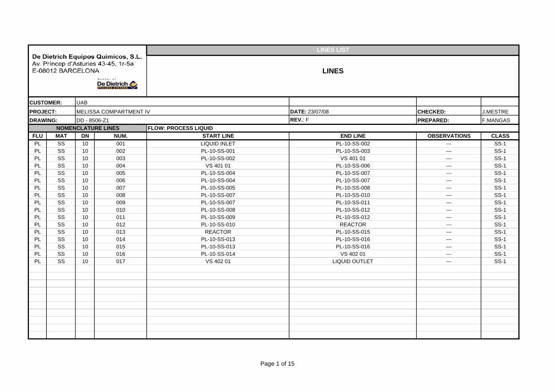
FLOW: PROCESS LIQUID FLU MAT DN NUM. START LINE END LINE OBSERVATIONS CLASSPL SS 10 001 LIQUID INLET PL-10-SS-002 --- SS-1PL SS 10 002 PL-10-SS-001 PL-10-SS-003 --- SS-1PL SS 10 003 PL-10-SS-002 VS 401 01 --- SS-1PL SS 10 004 VS 401 01 PL-10-SS-006 --- SS-1PL SS 10 005 PL-10-SS-004 PL-10-SS-007 --- SS-1PL SS 10 006 PL-10-SS-004 PL-10-SS-007 --- SS-1PL SS 10 007 PL-10-SS-005 PL-10-SS-008 --- SS-1PL SS 10 008 PL-10-SS-007 PL-10-SS-010 --- SS-1PL SS 10 009 PL-10-SS-007 PL-10-SS-011 --- SS-1PL SS 10 010 PL-10-SS-008 PL-10-SS-012 --- SS-1PL SS 10 011 PL-10-SS-009 PL-10-SS-012 --- SS-1PL SS 10 012 PL-10-SS-010 REACTOR --- SS-1PL SS 10 013 REACTOR PL-10-SS-015 --- SS-1PL SS 10 014 PL-10-SS-013 PL-10-SS-016 --- SS-1PL SS 10 015 PL-10-SS-013 PL-10-SS-016 --- SS-1PL SS 10 016 PL-10-SS-014 VS 402 01 --- SS-1PL SS 10 017 VS 402 01 LIQUID OUTLET --- SS-1
LINES LIST
LINES
CUSTOMER: UAB
MELISSA COMPARTMENT IVDD - 8506-Z1
NOMENCLATURE LINES
Page 1 of 15
PROJECT: DATE: 23/07/08 CHECKED: J.MESTREDRAWING: REV.: F PREPARED: F.MANGAS
FLOW: PROCESS LIQUID
LINES LIST
LINES
CUSTOMER: UAB
MELISSA COMPARTMENT IVDD - 8506-Z1
NOMENCLATURE LINESFLOW: PROCESS GAS
FLU MAT DN NUM. START LINE END LINE OBSERVATIONS CLASSPG SS 10 001 HX 407 01 PG-10-SS-004 --- SS-1PG SS 10 002 PG-10-SS-001 PG-10-SS-003 --- SS-1PG SS 10 003 PG-10-SS-002 PG-10-SS-005 --- SS-1PG SS 10 004 PG-10-SS-001 PG-10-SS-005 --- SS-1PG SS 10 005 PG-10-SS-004 HX 407 02 --- SS-1PG SS 10 006 HX 407 02 PG-10-SS-008 --- SS-1PG PA 10 007 PG-10-SS-006 PG-10-SS-008 --- SS-1PG SS 10 008 PG-10-SS-006 GAS OUTLET --- SS-1PG SS 10 009 HV 404 11 PAI-10-SS-002 --- SS-1
NOMENCLATURE LINES
Page 2 of 15
PROJECT: DATE: 23/07/08 CHECKED: J.MESTREDRAWING: REV.: F PREPARED: F.MANGAS
FLOW: PROCESS LIQUID
LINES LIST
LINES
CUSTOMER: UAB
MELISSA COMPARTMENT IVDD - 8506-Z1
NOMENCLATURE LINESFLOW:PROCESS AIR
FLU MAT DN NUM. START LINE END LINE OBSERVATIONS CLASSPAI SS 10 001 PROCESS AIR INLET PAI-10-SS-002 --- SS-2PAI SS 10 002 PAI-10-SS-001 CO2-10-SS-001 --- SS-2PAI SS 10 003 PAI-10-SS-001 REACTOR --- SS-1
NOMENCLATURE LINES
Page 3 of 15
PROJECT: DATE: 23/07/08 CHECKED: J.MESTREDRAWING: REV.: F PREPARED: F.MANGAS
FLOW: PROCESS LIQUID
LINES LIST
LINES
CUSTOMER: UAB
MELISSA COMPARTMENT IVDD - 8506-Z1
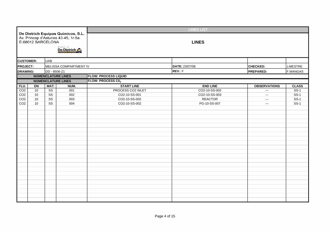
NOMENCLATURE LINESFLOW: PROCESS C02
FLU. DN MAT. NUM. START LINE END LINE OBSERVATIONS CLASSCO2 10 SS 001 PROCESS CO2 INLET CO2-10-SS-002 --- SS-1CO2 10 SS 002 CO2-10-SS-001 CO2-10-SS-003 --- SS-1CO2 10 SS 003 CO2-10-SS-002 REACTOR --- SS-1CO2 10 SS 004 CO2-10-SS-002 PG-10-SS-007 --- SS-1
NOMENCLATURE LINES
Page 4 of 15
PROJECT: DATE: 23/07/08 CHECKED: J.MESTREDRAWING: REV.: F PREPARED: F.MANGAS
FLOW: PROCESS LIQUID
LINES LIST
LINES
CUSTOMER: UAB
MELISSA COMPARTMENT IVDD - 8506-Z1
NOMENCLATURE LINESFLOW: PROCESS ACID
FLU. DN MAT. NUM. START LINE END LINE OBSERVATIONS CLASSPAC 10 PP 001 VS 406 01 PAC-10-SS-002 --- PPPAC 10 SS 002 PAC-10-PP-001 PAC-10-SS-003 --- SS-1PAC 10 SS 003 PAC-10-SS-002 REACTOR --- SS-1
NOMENCLATURE LINES
Page 5 of 15
PROJECT: DATE: 23/07/08 CHECKED: J.MESTREDRAWING: REV.: F PREPARED: F.MANGAS
FLOW: PROCESS LIQUID
LINES LIST
LINES
CUSTOMER: UAB
MELISSA COMPARTMENT IVDD - 8506-Z1
NOMENCLATURE LINESFLOW: PROCESS BASIC
FLU. DN MAT. NUM. START LINE END LINE OBSERVATIONS CLASSPBA 10 PP 001 VS 406 02 PBA-10-SS-002 --- PPPBA 10 SS 002 PAC-10-PP-001 PAC-10-SS-003 --- SS-1
NOMENCLATURE LINES
Page 6 of 15
PROJECT: DATE: 23/07/08 CHECKED: J.MESTREDRAWING: REV.: F PREPARED: F.MANGAS
FLOW: PROCESS LIQUID
LINES LIST
LINES
CUSTOMER: UAB
MELISSA COMPARTMENT IVDD - 8506-Z1
NOMENCLATURE LINESFLOW: GLYCOL
FLU. DN MAT. NUM. START LINE END LINE OBSERVATIONS CLASSGLY 15 SS 001 GLYCOL INLET VS 401 01 --- SS-1GLY 15 SS 002 VS 401 01 GLYCOL OUTLET --- SS-1GLY 15 SS 003 GLYCOL INLET HX 405 02 --- SS-1GLY 15 SS 004 HX 405 02 GLYCOL OUTLET --- SS-1GLY 15 SS 005 GLYCOL INLET HX 407 01 --- SS-1GLY 15 SS 006 HX 407 01 GLYCOL OUTLET --- SS-1GLY 15 SS 007 GLYCOL INLET VS 402 01 --- SS-1GLY 15 SS 008 VS 402 01 GLYCOL OUTLET --- SS-1
NOMENCLATURE LINES
Page 7 of 15
PROJECT: DATE: 23/07/08 CHECKED: J.MESTREDRAWING: REV.: F PREPARED: F.MANGAS
FLOW: PROCESS LIQUID
LINES LIST
LINES
CUSTOMER: UAB
MELISSA COMPARTMENT IVDD - 8506-Z1
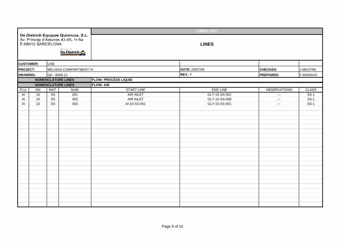
NOMENCLATURE LINESFLOW: AIR
FLU. DN MAT. NUM. START LINE END LINE OBSERVATIONS CLASSAI 10 SS 001 AIR INLET GLY-15-SS-002 --- SS-1AI 10 SS 002 AIR INLET GLY-15-SS-008 --- SS-1AI 10 SS 003 AI-10-SS-001 GLY-15-SS-001 --- SS-1
NOMENCLATURE LINES
Page 8 of 15
PROJECT: DATE: 23/07/08 CHECKED: J.MESTREDRAWING: REV.: F PREPARED: F.MANGAS
FLOW: PROCESS LIQUID
LINES LIST
LINES
CUSTOMER: UAB
MELISSA COMPARTMENT IVDD - 8506-Z1
NOMENCLATURE LINESFLOW: INOCULUM
FLU. DN MAT. NUM. START LINE END LINE OBSERVATIONS CLASSIN 15 SS 001 INOCULUM INLET REACTOR --- SS-1
NOMENCLATURE LINES
Page 9 of 15
PROJECT: DATE: 23/07/08 CHECKED: J.MESTREDRAWING: REV.: F PREPARED: F.MANGAS
FLOW: PROCESS LIQUID
LINES LIST
LINES
CUSTOMER: UAB
MELISSA COMPARTMENT IVDD - 8506-Z1
NOMENCLATURE LINESFLOW: STEAM
FLU. DN MAT. NUM. START LINE END LINE OBSERVATIONS CLASSST 15 SS 001 STEAM INLET SAMPLE VALVE REACTOR --- SS-2ST 15 SS 002 ST-15-SS-001 PL-10-SS-001 --- SS-2ST 15 SS 003 ST-15-SS-001 GLY-15-SS-002 --- SS-2ST 15 SS 004 ST-15-SS-001 VT-15-SS-001 --- SS-2ST 15 SS 005 ST-15-SS-001 PL-10-SS-004 --- SS-2ST 15 SS 006 ST-15-SS-005 VS 401 01 --- SS-2ST 15 SS 007 ST-15-SS-005 PL-10-SS-005 --- SS-2ST 15 SS 008 ST-15-SS-005 PL-10-SS-006 --- SS-2ST 15 SS 009 ST-15-SS-005 SAMPLE VALVE (VS 401 07) --- SS-2ST 15 SS 010 ST-15-SS-001 CO2-10-SS-002 --- SS-2ST 15 SS 011 STEAM INLET IN-10-SS-001 --- SS-2ST 15 SS 012 STEAM INLET PG-10-SS-001 --- SS-2ST 15 SS 013 ST-15-SS-012 PG-10-SS-004 --- SS-2ST 15 SS 014 ST-15-SS-012 PG-10-SS-002 --- SS-2ST 15 SS 015 STEAM INLET PL-10-SS-013 --- SS-2ST 15 SS 016 ST-15-SS-015 PL-10-SS-015 --- SS-2ST 15 SS 017 ST-15-SS-063 ST-15-SS-063 --- SS-2ST 15 SS 018 ST-15-SS-015 VT-15-SS-002 --- SS-2ST 15 SS 019 ST-15-SS-015 GLY-15-SS-008 --- SS-2ST 15 SS 020 ST-15-SS-015 VS 402 01 --- SS-2ST 15 SS 021 PL-10-SS-003 ST-15-SS-022 --- SS-2ST 15 SS 022 ST-15-SS-021 ST-15-SS-032 --- SS-2ST 15 SS 023 GLY-15-SS-001 ST-15-SS-022 --- SS-2ST 15 SS 024 INLET STEAM --- SS-2ST 15 SS 025 PL-10-SS-004 ST-15-SS-022 --- SS-2
NOMENCLATURE LINES
Page 10 of 15
PROJECT: DATE: 23/07/08 CHECKED: J.MESTREDRAWING: REV.: F PREPARED: F.MANGAS
FLOW: PROCESS LIQUID
LINES LIST
LINES
CUSTOMER: UAB
MELISSA COMPARTMENT IVDD - 8506-Z1
NOMENCLATURE LINESFLOW: STEAM
FLU. DN MAT. NUM. START LINE END LINE OBSERVATIONS CLASSST 15 SS 026 PL-10-SS-011 ST-15-SS-022 --- SS-2ST 15 SS 027 PL-10-SS-005 ST-15-SS-026 --- SS-2ST 15 SS 028 PL-10-SS-006 ST-15-SS-026 --- SS-2ST 15 SS 029 PL-10-SS-010 ST-15-SS-026 --- SS-2ST 15 SS 030 ST-15-SS-001 PL-10-SS-009 --- SS-2ST 15 SS 031 ST-15-SS-001 PL-10-SS-008 --- SS-2ST 15 SS 032 ST-15-SS-034 ST-15-SS-022 --- SS-2ST 15 SS 033 PBA-10-SS-002 ST-15-SS-032 --- SS-2ST 15 SS 034 PL-10-SS-012 ST-15-SS-032 --- SS-2ST 15 SS 035 PL-10-SS-004 OUT --- SS-2ST 15 SS 036 ST-15-SS-035 ST-15-SS-035 --- SS-2ST 15 SS 037 CO2-10-SS-003 ST-15-SS-039 --- SS-2ST 15 SS 038 REACTOR ST-15-SS-039 --- SS-2ST 15 SS 039 ST-15-SS-037 OUT --- SS-2ST 15 SS 040 ST-15-SS-039 OUT --- SS-2ST 15 SS 041 PG-10-SS-005 ST-15-SS-042 --- SS-2ST 15 SS 042 ST-15-SS-041 OUT --- SS-2ST 15 SS 043 PG-10-SS-003 ST-15-SS-041 --- SS-2ST 15 SS 044 ST-15-SS-042 ST-15-SS-042 --- SS-2ST 15 SS 045 PL-10-SS-014 OUT --- SS-2ST 15 SS 046 PL-10-SS-015 ST-15-SS-045 --- SS-2ST 15 SS 047 ST-15-SS-045 ST-15-SS-045 --- SS-2ST 15 SS 048 IN-10-SS-010 ST-15-SS-049 --- SS-2ST 15 SS 049 PAI-10-SS-003 ST-15-SS-037 --- SS-2ST 15 SS 050 ST-15-SS-051 ST-15-SS-052 --- SS-2
NOMENCLATURE LINES
Page 11 of 15
PROJECT: DATE: 23/07/08 CHECKED: J.MESTREDRAWING: REV.: F PREPARED: F.MANGAS
FLOW: PROCESS LIQUID
LINES LIST
LINES
CUSTOMER: UAB
MELISSA COMPARTMENT IVDD - 8506-Z1
NOMENCLATURE LINESFLOW: STEAM
FLU. DN MAT. NUM. START LINE END LINE OBSERVATIONS CLASSST 15 SS 051 PL-10-SS-016 ST-15-SS-050 --- SS-2ST 15 SS 052 GLY-15-SS-007 ST-15-SS-050 --- SS-2ST 15 SS 053 VT-15-SS-002 ST-15-SS-050 --- SS-2ST 15 SS 054 PL-10-SS-017 ST-15-SS-050 --- SS-2ST 15 SS 055 ST-15-SS-050 OUT --- SS-2ST 15 SS 056 ST-15-SS-055 ST-15-SS-055 --- SS-2ST 15 SS 057 INLET STEAM HV 402 01 (SAMPLE VALVE) --- SS-2ST 15 SS 058 INLET STEAM ST-15-SS-059 --- SS-2ST 15 SS 059 ST-15-SS-058 PBA-10-SS-002 --- SS-2ST 15 SS 060 ST-15-SS-058 PAC-10-SS-002 --- SS-2ST 15 SS 061 ST-15-SS-022 OUT --- SS-2ST 15 SS 062 ST-15-SS-061 ST-15-SS-061 --- SS-2ST 15 SS 063 PL-10-SS-017 OUT --- SS-2ST 15 SS 064 PL-10-SS-007 ST-15-SS-026 --- SS-2ST 15 SS 065 ST-15-SS-066 ST-15-SS-066 --- SS-2ST 15 SS 066 REACTOR OUT --- SS-2ST 15 SS 067 PAC-10-SS-003 ST-15-SS-034 --- SS-2ST 15 SS 068 ST-15-SS-010 PAI-10-SS-003 --- SS-2
NOMENCLATURE LINES
Page 12 of 15
PROJECT: DATE: 23/07/08 CHECKED: J.MESTREDRAWING: REV.: F PREPARED: F.MANGAS
FLOW: PROCESS LIQUID
LINES LIST
LINES
CUSTOMER: UAB
MELISSA COMPARTMENT IVDD - 8506-Z1
NOMENCLATURE LINESFLOW: VENT
FLU. DN MAT. NUM. START LINE END LINE OBSERVATIONS CLASSVT 15 SS 001 VS 401 01 ATM --- SS-1VT 15 SS 002 VS 402 01 ATM --- SS-1VT 15 PP 003 VS 406 02 ATM --- SS-1VT 15 PP 004 VS 406 01 ATM --- SS-1
NOMENCLATURE LINES
Page 13 of 15
PROJECT: DATE: 23/07/08 CHECKED: J.MESTREDRAWING: REV.: F PREPARED: F.MANGAS
FLOW: PROCESS LIQUID
LINES LIST
LINES
CUSTOMER: UAB
MELISSA COMPARTMENT IVDD - 8506-Z1
NOMENCLATURE LINESFLOW: WATER
FLU. DN MAT. NUM. START LINE END LINE OBSERVATIONS CLASSWT 15 SS 001 WATER INLET WT-15-SS-02 --- SS-2WT 15 SS 002 WT-15-SS-002 WT-15-SS-02 --- SS-2WT 15 SS 003 COOLING WATER INLET --- SS-2
NOMENCLATURE LINES
Page 14 of 15
PROJECT: DATE: 23/07/08 CHECKED: J.MESTREDRAWING: REV.: F PREPARED: F.MANGAS
FLOW: PROCESS LIQUID
LINES LIST
LINES
CUSTOMER: UAB
MELISSA COMPARTMENT IVDD - 8506-Z1
NOMENCLATURE LINESFLOW: ANTIFOAM / GAS VACUMM BREACKING
FLU. DN MAT. NUM. START LINE END LINE OBSERVATIONS CLASSAF 10 SS 001 ANTIFOAM INLET REACTOR (FUTURE) SS-1
IR 15 SS 001 GAS VACUMM BREACKING INLET --- SS-1
NOMENCLATURE LINES
Page 15 of 15
CUSTOMER:PROJECT: DATE 25/07/2008 CHECKEDDRAWING: REV: F PREPARED:
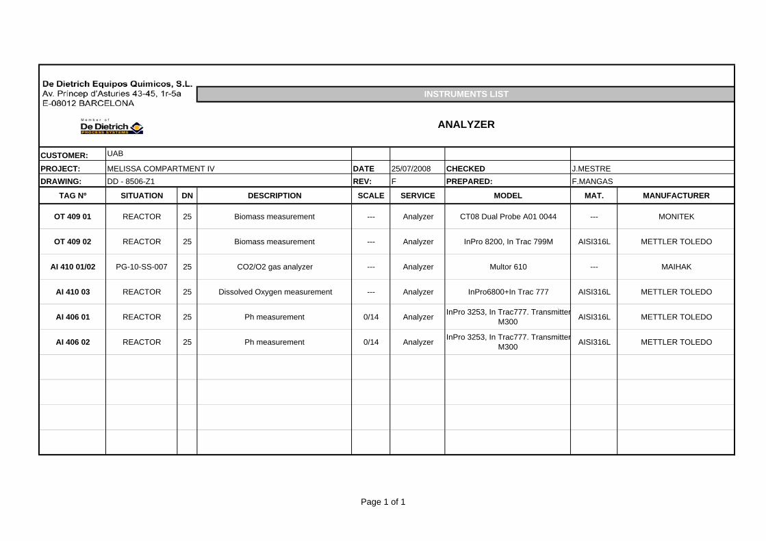
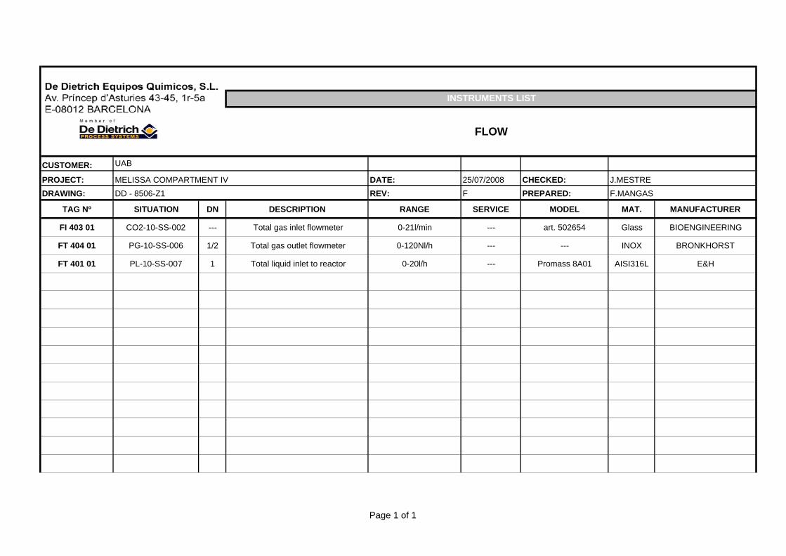
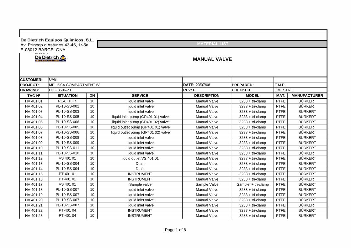
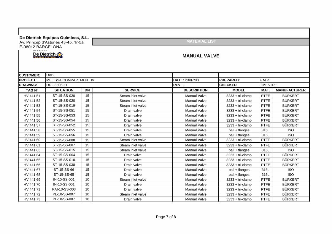
TAG Nº SITUATION DN DESCRIPTION SCALE SERVICE MODEL MAT. MANUFACTURER
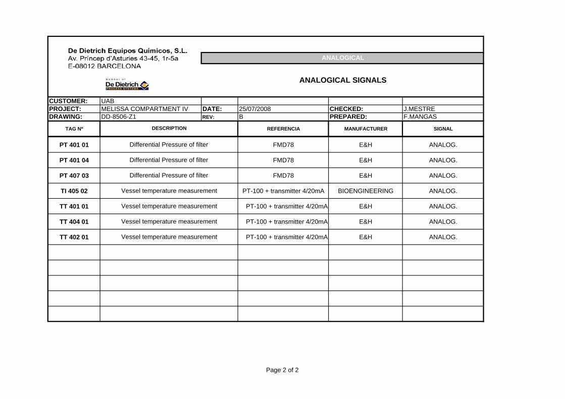
CUSTOMER: UABPROJECT: MELISSA COMPARTMENT IV DATE: 25/07/2008 CHECKED: J.MESTREDRAWING: DD-8506-Z1 REV: B PREPARED: F.MANGAS
TAG Nº REFERENCIA MANUFACTURER SIGNAL
ANALOGICAL
ANALOGICAL SIGNALS
DESCRIPTION
PT 401 01 FMD78 E&H ANALOG.
PT 401 04 FMD78 E&H ANALOG.
PT 407 03 FMD78 E&H ANALOG.
TI 405 02 PT-100 + transmitter 4/20mA BIOENGINEERING ANALOG.
TT 401 01 PT-100 + transmitter 4/20mA E&H ANALOG.
TT 404 01 PT-100 + transmitter 4/20mA E&H ANALOG.
TT 402 01 PT-100 + transmitter 4/20mA E&H ANALOG.
Vessel temperature measurement
Vessel temperature measurement
Differential Pressure of filter
Differential Pressure of filter
Vessel temperature measurement
Differential Pressure of filter
Vessel temperature measurement
Page 2 of 2
MELiSSA TECHNICAL NOTE 87.2.11
This document is confidential property of the MELiSSA partners and shall not be used, duplicated, modified or transmitted without their authorization
Memorandum of Understanding 19071/05/NL/CP 99
7. ANNEX II: SPECIFICATIONS
7.1. Equipment specifications
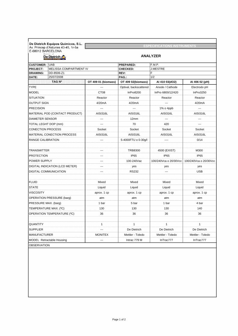
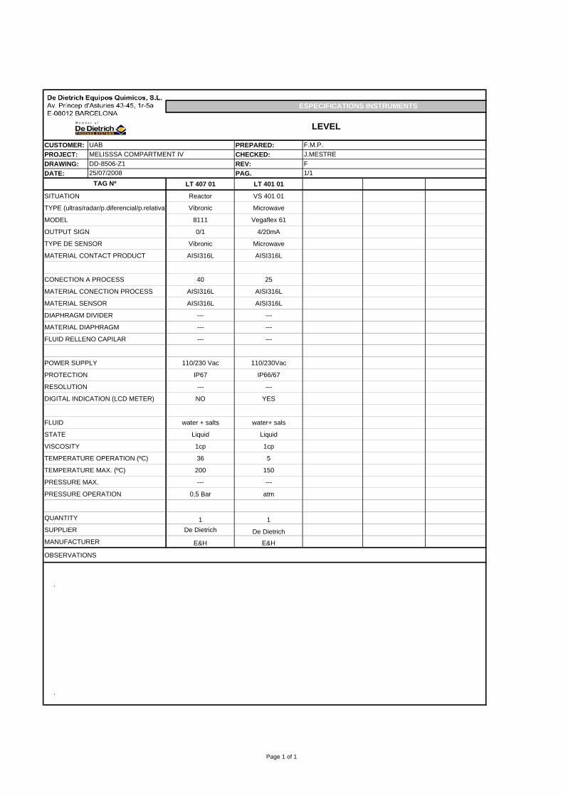
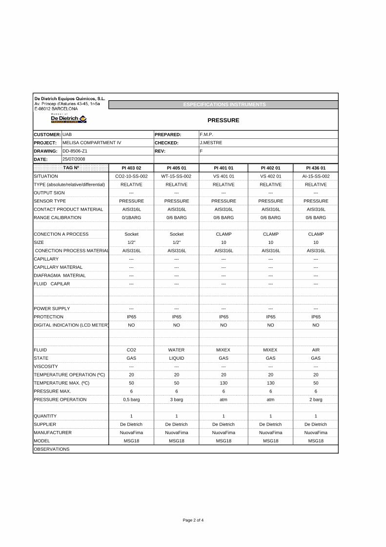
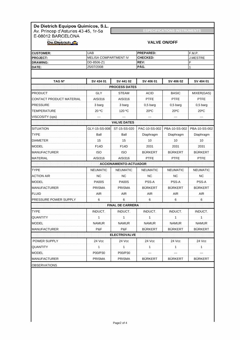
7.2. Instrument specifications
EQUIPMENT ESPECIFICATIONS
DOSING PUMP
CUSTOMER: UAB DATE: 25/07/2008PROJECT: MELISSA COMPARTMENT IVa ITEM: GP40101/02 PREPARED: F.M.P.DRAWING: Attached files REV: C CHECKED: J.MESTRETYPE sanity NORM ---- GENERAL DIMENSIONS (mm)MODEL ECODOS SERVICE ---- 425(L) 220 (A) 570 (H)MANUFACT. LEWA SITUATION ----
CONDITIONS OF WORKCONCEPT DESCRIPTION
PRODUCT Water solutionUNITS DESIGN
TEMPERATURE °C 5DENSITY kg/m³ 1VISCOSITY cst 1CONTENT OF SOLID %peso ---
SOLID SIZE Ø mm ---
TOTAL FLOW l/h 0-4TOTAL HEAD mcl 0,5STATIC HEAD mcl --INLET PRESSURE HEAD mcl --AVAILABLE NPSH mcl --
MATERIALS NOZZLES CHARACTERISTICS PART MATERIAL POSITION SIZE NORMBODY PTFE SUCTION 25 SHAFT POWER CVIMPELLER --- DISCHARGE 25 EFFICIENCY %SHAFT --- SERVICE NPSH VALUE mclGASKET PTFE WEIGHT TESTMEMBRANE PTFE PUMP -- kg FUNCTIONINGVALVES --- PLATE -- kg HYDROSTATICS barBALL PTFE TOTAL -- kg
TIGHTNESS
TYPE MECHANICAL SEAL SINGLE DOUBLE
MOUNTING REF:MATERIALSQUENCH LIQUID OTHER
MOTOR TYPEMANUFACTURER ----SUPPLER LEWASIZE ---TYPE PROTECTION IP55ELECTRIC VOLTAGE 230VPHASES 2FREQUENCY 50HzRATED POWER 0,25 kWSPEED rpmAIR PRESSURE bar
ELECTRICAL MOTOR
MEDIUM DATE
OPERATION
OPERATING DATA
DESCRIPTION
Page 1
EQUIPMENT ESPECIFICATIONS
AGITATOR
CUSTOMER: UAB DATE: 25/07/2008
PROJECT: MELISSA COMPARTMENT IV TAG: VS-401 01 F.M.P.
DETAILS OF CONSTRUCTIONType and norm Vertical cylinder with Normalized CoversDimension: Ø500×740mm(Cylindrical lenght)Thick: Top Head: 5 mm Bottom Head: 5 mm Corrosion mm Cylindric 4mmYES NO CONCEPT QUANTITY OBSERVATIONS
SUPPORT 4DESIGN FOR OUTSIDETYPE HEATINGDESIGN CODEX RAYSINSULATION Thick (mm): 50mmINSULATION SUPPORTSURFACE FINISH INSIDESURFACE FINISH OUTSIDEPAINTINGLIFTING LUGBAFFLEAGITATOR (see attached file of especifications agitator)
ENTRADA SALIDA ENTRADA SALIDAFLUIDO AGUA GLICOLCONCENTRACIÓN DEL LÍQUIDO %CAUDAL l/h 1750 2350TEMPERATURA DE FLUIDO °C 24 20 0 5PÉRDIDA DE CARGA M.C.A. 1 1PESO ESPECÍFICO FLUIDO kg/m³VISCOSIDAD DEL FLUIDO cpVISCOSIDAD DE LA PARED cpCALOR ESPECÍFICO FLUIDO kcal/ kg °C 1 0,54CONDUCTIVIDAD TÉRMICA kcal/ h m °CTEMPERATURA DE OPERACIÓN MÁXIMA °CPRESIÓN DE OPERACIÓN MÁXIMA bar 3 3FACTOR DE ENSUCIAMIENTO m² h °C/kcalPOTENCIA DE INTERCAMBIOINTERCAMBIADOR DE PLACASPRESIÓN DE DISEÑO bar 4 4
PRESIÓN DE PRUEBA barTEMPERATURA DE DISEÑO °C 50 -10
SUPERFICIE INTERCAMBIO (Calculada) m²SUPERFICIE INTERCAMBIO (Real) m²POTENCIA INTERCAMBIO kcal/h 7000CAPACIDAD lCOEFICIENTE DE TRANSMISIÓN kcal/m².°C.h LIMPIO EN SERVICIOSOBREDIMENSIONAMIENTO %PÉRDIDA DE CARGA CALCULADA mcaNÚMERO DE CANALESNÚMERO TOTAL DE PLACASDATOS DE CONSTRUCCIÓN
Descripción Cantidad Longitud Ancho Espesor Material ObservaciónPLACAS ASTM-316BASTIDOR
CODE PROJECT: DD‐8506‐Z1 Rev. A CUSTOMER: UAB PROJECT: MELISSA COMPARMENT IVa DATE: 06/05/2008
PREPARED: F.M.P.
PAGE 2 of 44
Ref. PRK‐005257
1. INTRODUCTION
The development of a Hazard Analysis and Operability Study (HAZOP) has a dual purpose: on the one hand, rigorous and systematic identification of hazards, as an integral part of Risk Analysis of an industrial plant and, secondly, the analysis of operating problems that could jeopardize the fulfilment of the design goals. In both cases, this analysis makes it possible to define a series of corrective actions (short, medium and long term), appropriate to each case. The objectives of any HAZOP study can be summarized as follows:
− Identifying areas, hazardous procedures or operations in the facility. − Identification of Major Accidents. Definition of accident scenarios for subsequent
calculation of consequences (only in facilities that require a Safety Report). − Study of the design characteristics that could lead to dangerous incidents, and
operability problems. − Carrying out a systematic study of the different sections or nodes of a plant with
potential risks. The survey is always done jointly by experts in different fields (design, process, instrumentation...), integrated into a multidisciplinary team.
− Proposal for corrective actions and protection systems needed. The procedure or methodology for conducting such studies schematized in summary diagrams which are attached in ANNEX 1, complemented with a general guide word glossary (see Annex 2).
CODE PROJECT: DD‐8506‐Z1 Rev. A CUSTOMER: UAB PROJECT: MELISSA COMPARMENT IVa DATE: 06/05/2008
PREPARED: F.M.P.
PAGE 3 of 44
Ref. PRK‐005257
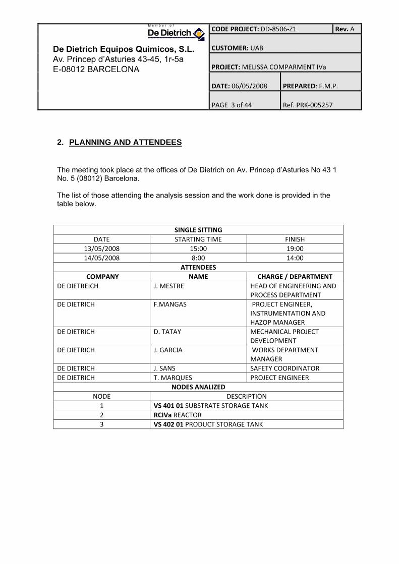
2. PLANNING AND ATTENDEES
The meeting took place at the offices of De Dietrich on Av. Princep d’Asturies No 43 1 No. 5 (08012) Barcelona. The list of those attending the analysis session and the work done is provided in the table below.
SINGLE SITTING DATE STARTING TIME FINISH
13/05/2008 15:00 19:00 14/05/2008 8:00 14:00
ATTENDEES COMPANY NAME CHARGE / DEPARTMENT
DE DIETREICH J. MESTRE HEAD OF ENGINEERING AND PROCESS DEPARTMENT
DE DIETRICH F.MANGAS PROJECT ENGINEER, INSTRUMENTATION AND HAZOP MANAGER
DE DIETRICH D. TATAY MECHANICAL PROJECT DEVELOPMENT
DE DIETRICH J. GARCIA WORKS DEPARTMENT MANAGER
DE DIETRICH J. SANS SAFETY COORDINATOR DE DIETRICH T. MARQUES PROJECT ENGINEER
NODES ANALIZED NODE DESCRIPTION 1 VS 401 01 SUBSTRATE STORAGE TANK 2 RCIVa REACTOR 3 VS 402 01 PRODUCT STORAGE TANK
CODE PROJECT: DD‐8506‐Z1 Rev. A CUSTOMER: UAB PROJECT: MELISSA COMPARMENT IVa DATE: 06/05/2008
PREPARED: F.M.P.
PAGE 4 of 44
Ref. PRK‐005257
3. BRIEF DESCRIPTION OF THE FACILITIES SUBJECT TO STUDY
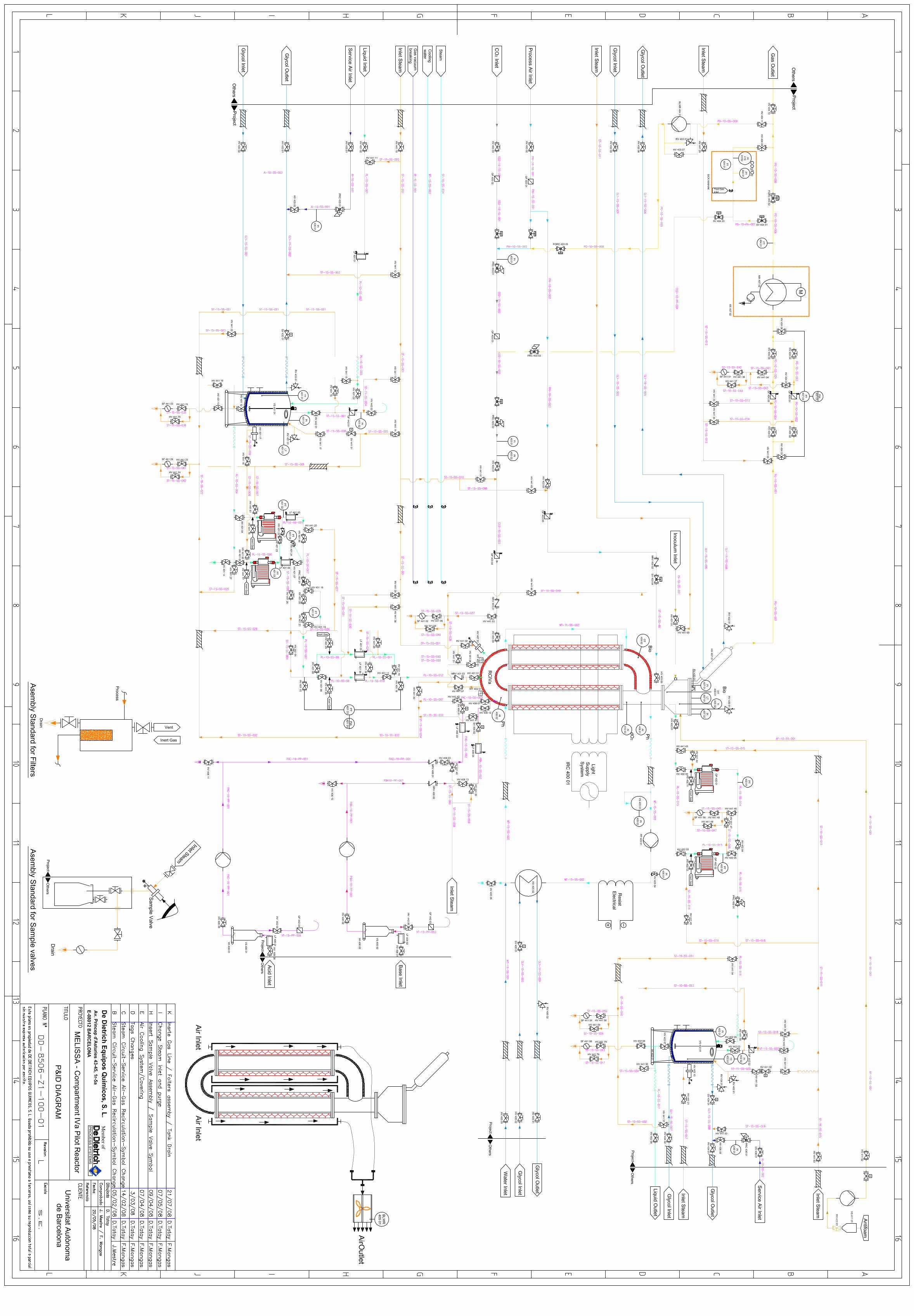
Compartment IV of the MELISSA cycle, comprises a photobioreactor project for the cultivation of the cyanobacteria Spirulina platensis.
The substrate of the bacteria is driven from the storage tank (VS 401 01), through a pumping system formed by two membrane pumps which feed it into the bioreactor (RCIVa), the bacteria in question is fed directly into the reactor, which also receives an air and CO2 injection.
The resulting products are essentially a gas phase which leaves the reactor at the top after passing through a small exchanger to condense water vapour dregs, and a liquid phase that is pumped to a holding tank (VS 402 01) by a pumping unit formed by two other membrane pumps.
The energy needed for the transformation of the substrate, is given in the form of visible radiation produced by a set of lights arranged around the glass sections that make up the reactor. The heat generated by these lights is dissipated by a dual cooling system formed by a closed water circuit and the constant movement of air through the interior of the casing where the lights are found.
Given the need to work with all the equipment and pipes free of contamination, there are several steam inlets spread over different points of the system that allow the entire installation to be sterilised.
CODE PROJECT: DD‐8506‐Z1 Rev. A CUSTOMER: UAB PROJECT: MELISSA COMPARMENT IVa DATE: 06/05/2008
PREPARED: F.M.P.
PAGE 5 of 44
Ref. PRK‐005257
4. LIST OF DOCUMENTS CONSULTED
The analysis has been developed consulting the drawings which are listed below: P & IDs:
- DD-8506-Z1-100-01 J Review
Documents:
- Technical Specifications for the Re-design of the Compartment IVa Pilot Reactor
- Technical note 37.2 Version 1
A true copy for all the original documents consulted is attached in ANNEX 4.
CODE PROJECT: DD‐8506‐Z1 Rev. A CUSTOMER: UAB PROJECT: MELISSA COMPARMENT IVa DATE: 06/05/2008
PREPARED: F.M.P.
PAGE 6 of 44
Ref. PRK‐005257
5. HAZOP DEVELOPMENT. NODES
The analysis concept of the facilities is based on the detailed breakdown of equipment, systems and operations to be performed in the facility. To conduct this detailed study specific parts of the plant called nodes have been identified. During the NODES selection, we have taken into consideration the parts and operating conditions of the facility regarded as representative from an operation and safety viewpoint, maintaining a certain criterion of continuity for each of them, according to the running of the installation. The nodes selected in the facilities are as follows:
ANALIZED NODES 1. VS 401 01 SUBSTRATE STORAGE TANK 2. RCIVa REACTOR 3. VS402 02 PRODUCT STORAGE TANK
For each node the relevant parameters are analysed, applying to each one the guide words and deviations, allowing the possible causes and their consequences to be suggested. The last column of the tables includes the overall improvement actions and comments, arising out of the meeting. The tables reflecting the development of the HAZOP study are attached in ANNEX 3.
CODE PROJECT: DD‐8506‐Z1 Rev. A CUSTOMER: UAB PROJECT: MELISSA COMPARMENT IVa DATE: 06/05/2008
PREPARED: F.M.P.
PAGE 7 of 44
Ref. PRK‐005257
6. CONCLUSIONS
The development of a HAZOP type analysis on the Melissa project–Compartment IVa Pilot Reactor, has allowed the following considerations to be highlighted:
− The information provided has been sufficient for the proper development of analysis at this stage of the process, especially considering the direct input of the engineers in charge of the project.
− The HAZOP study has identified some important improvements to safety and
the proper operation of the new facility, which are set out in Annex V. These improvements are mainly related to instrumentation and control of the operation, superfluous safeguards, and checks on the proper design of the facility.
CODE PROJECT: DD‐8506‐Z1 Rev. A CUSTOMER: UAB PROJECT: MELISSA COMPARMENT IVa DATE: 06/05/2008
PREPARED: F.M.P.
PAGE 8 of 44
Ref. PRK‐005257
ANNEX 1. HAZOP PROCUDURE
CODE PROJECT: DD‐8506‐Z1 Rev. A CUSTOMER: UAB PROJECT: MELISSA COMPARMENT IVa DATE: 06/05/2008
PREPARED: F.M.P.
PAGE 9 of 44
Ref. PRK‐005257
The HAZOP procedure is based on the critical and systematic analysis of a process from the deviations that may occur in certain parameters of the same, identifying causes, possible consequences and detection mechanisms. A multidisciplinary group of people, knowledgeable about the process, analyse these deviations led by a chairperson who systematises the analysis and maintains the pace of the meetings. One person acts as secretary and notes down for each deviation:
− The causes which lead to it. − The possible consequences. − The manner, in which such a deviation can be prevented, detected or is
automatically controlled. The selection of a person from outside the company to act as chairperson or secretary is often very useful for introducing different viewpoints. The documentary basis of the analysis is a piping and instrumentation (P & ID) diagram, which applies the following methods:
− A NODE is selected. Generally this is some equipment or section of pipe, or a step in the process in the case of batch plants or semi-batch plants and the role of the node is indicated (INTENTION).
− A certain process PARAMETER is chosen (P, T, F, etc...), to which the previous
GUIDE WORD is applied to obtain a certain deviation in the process. In order to be systematic and not forget any possibility, a checklist like the one presented in Annex 2 should be implemented.
− A GUIDE WORD is selected.
− For each deviation and in accordance with the table formats included in Annex 3, the following will be listed:
· The causes that can produce it. · The consequences that can occur if the deviation spreads unchecked. · The indications and controls provided to prevent the deviation acquiring
critical values.
CODE PROJECT: DD‐8506‐Z1 Rev. A CUSTOMER: UAB PROJECT: MELISSA COMPARMENT IVa DATE: 06/05/2008
PREPARED: F.M.P.
PAGE 10 of 44
Ref. PRK‐005257
ANNEX 2. GUIDE WORD LIST
CODE PROJECT: DD‐8506‐Z1 Rev. A CUSTOMER: UAB PROJECT: MELISSA COMPARMENT IVa DATE: 06/05/2008
PREPARED: F.M.P.
PAGE 11 of 44
Ref. PRK‐005257
GUIDE WORDS MEANING PARAMETERS DEVIATION MORE (Knowlton)
MORE THAN (Kletz)
GREATER
LESS (Knowlton)
LESS THAN (Kletz)
LESS
Quantitative Increase Quantitative Decrease
Process Variables:
P (Pressure)
T (Temperature)
F (Flow)
Q (quantity)
L (Level)
Properties:
μ (viscosity)
Y (humidity)
Greater / less
pressure
Higher / lower
temperature
More / less flow
More / less quantity
Higher/ lower level
Higher / lower
viscosity
Higher/ lower
humidity
NO (Knowlton)
NO (Kletz)
Denial of design specifications
Process Variables:
P (Pressure)
F (Flow)
Q (quantity)
L (Level)
Empty
No flow
...
Empty
CONTRARY
(Knowlton)
LOSS OF
DIRECTION
The contrary of the design purpose
Process Variables:
F (Flow)
Reverse Flow
AS WELL AS
(Knowlton)
AS MUCH/MANY AS
EXCESS OF (Kletz)
Qualitative Increase (Knowlton) More components present in the system than there should be
Composition
Phase
Concentration increase Another specification impurities (air, water, acids, corrosion products) Contamination This additional phase or accumulation (liquid, vapour, solid)
PARTLY Qualitative Decrease (Knowlton)
Composition
Concentration decrease
CODE PROJECT: DD‐8506‐Z1 Rev. A CUSTOMER: UAB PROJECT: MELISSA COMPARMENT IVa DATE: 06/05/2008
PREPARED: F.M.P.
PAGE 12 of 44
Ref. PRK‐005257
A PART OF (Knowlton / Kletz)
Any variance to what it should be (Kletz)
Change in the ratio of Components Component missing
DIFFERENT FROM OTHER TYPE (Knowlton / Kletz)
Complete replacement (Knowlton) Anything that can happen apart from the normal operation (Kletz)
Composition Substance Operation
Incorrect composition Another product Catalytic Change Start-up Stop Operation with excess Performance Operation with low Performance Alternative mode of operation Maintenance Inspection Weather
CODE PROJECT: DD‐8506‐Z1 Rev. A CUSTOMER: UAB PROJECT: MELISSA COMPARMENT IVa DATE: 06/05/2008
PREPARED: F.M.P.
PAGE 13 of 44
Ref. PRK‐005257
FAILURE IN
Unexpected general failure In services Operation failure material Failure
Services Operation Material
A.S. (air) Steam Power (electricity) Nitrogen / inertization Water Stirring Chilling Filling Emptying Drainage Corrosion Erosion Voltage:
CONTAINMENT
Loss
Containment
Loss of containment
CODE PROJECT: DD‐8506‐Z1 Rev. A CUSTOMER: UAB PROJECT: MELISSA COMPARMENT IVa DATE: 06/05/2008
PREPARED: F.M.P.
PAGE 14 of 44
Ref. PRK‐005257
OPERATION
In addition (incidences at start-up) In addition (incidences in Stopping) Furthermore (operations not authorised) Furthermore (adverse weather) Furthermore (domino effect)
Start-up Stop Normal operations Normal operations Normal operations
Incidents at start-up Incidents stopping Unauthorised operations Incidents due to Adverse weather Affected by domino effect from nearby tank.
CODE PROJECT: DD‐8506‐Z1 Rev. A CUSTOMER: UAB PROJECT: MELISSA COMPARMENT IVa DATE: 06/05/2008
PREPARED: F.M.P.
PAGE 15 of 44
Ref. PRK‐005257
ANNEX 3. HAZOP TABLES
CODE PROJECT: DD‐8506‐Z1 Rev. A CUSTOMER: UAB PROJECT: MELISSA COMPARMENT IVa DATE: 06/05/2008
PREPARED: F.M.P.
PAGE 16 of 44
Ref. PRK‐005257
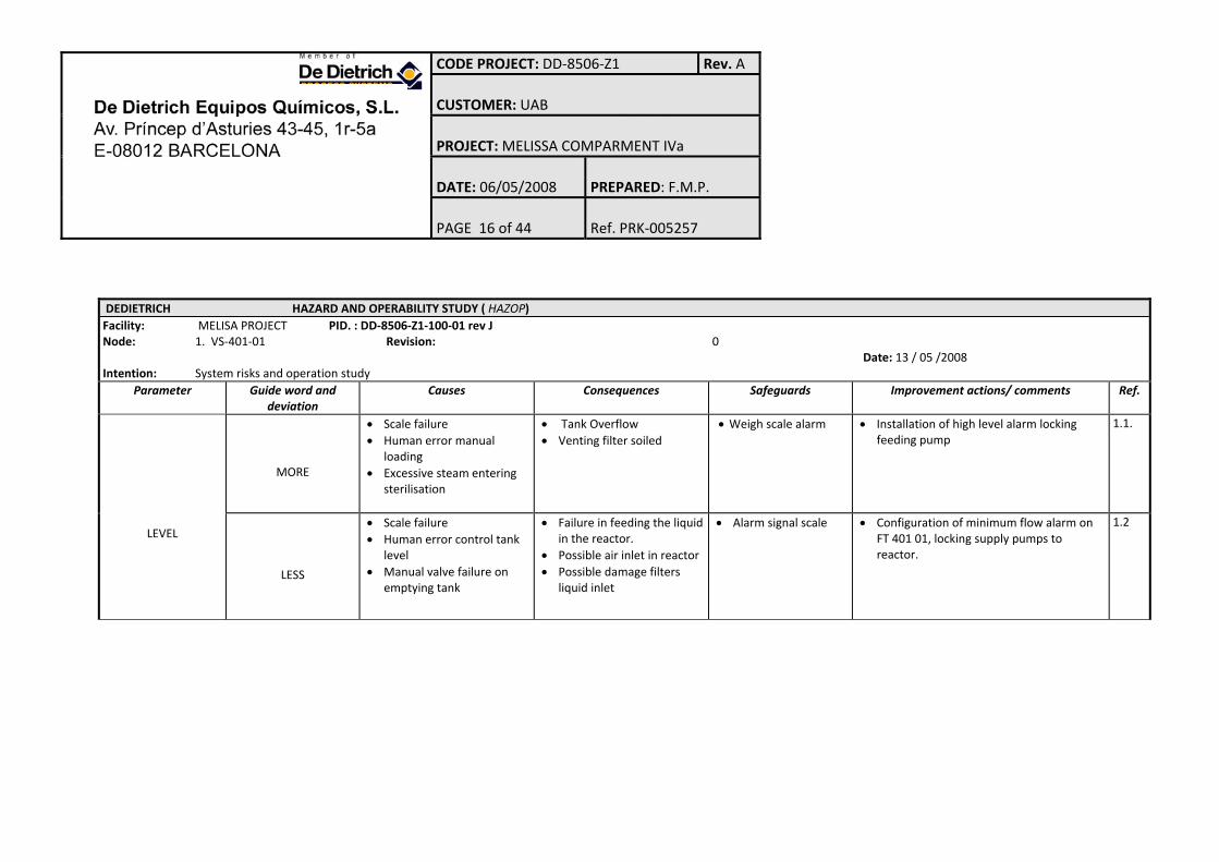
DEDIETRICH HAZARD AND OPERABILITY STUDY ( HAZOP) Facility: MELISA PROJECT PID. : DD‐8506‐Z1‐100‐01 rev J Node: 1. VS‐401‐01 Revision: 0 Date: 13 / 05 /2008 Intention: System risks and operation study
Parameter Guide word and deviation
Causes
Consequences
Safeguards
Improvement actions/ comments Ref.
LEVEL
MORE
• Scale failure • Human error manual
loading • Excessive steam entering
sterilisation
• Tank Overflow • Venting filter soiled
• Weigh scale alarm
• Installation of high level alarm locking feeding pump
1.1.
LESS
• Scale failure • Human error control tank
level • Manual valve failure on
emptying tank
• Failure in feeding the liquid in the reactor.
• Possible air inlet in reactor • Possible damage filters
liquid inlet
• Alarm signal scale • Configuration of minimum flow alarm on FT 401 01, locking supply pumps to reactor.
1.2
CODE PROJECT: DD‐8506‐Z1 Rev. A CUSTOMER: UAB PROJECT: MELISSA COMPARMENT IVa DATE: 06/05/2008
PREPARED: F.M.P.
PAGE 17 of 44
Ref. PRK‐005257
DEDIETRICH HAZARD AND OPERABILITY STUDY ( HAZOP) Facility: MELISA PROJECT PID. : DD‐8506‐Z1‐100‐01 rev J Node: 1. VS‐401‐01 Revision: 0 Date: 13 / 05 /2008 Intention: System risks and operation study
Parameter Guide word and deviation
Ref. Causes
Consequences
Safeguard
s Improvement actions/ comments
PRESSURE
MORE
• Vent closed during filling operation, human error
• Steam inlet to casing venting closed
• Clogged venting filter
• Over pressure in the tank (safety valve operation)
• Possible entry of unfiltered air (via safety valve)
• Safety valve • Local Gauge PI40101
• Installation of pressure switch alarm • Direct safety valve discharge to a collecting
area safe for people and facilities
2.1 2.2
LESS
• Venting obstruction during feeding the reactor
• Venting obstruction during tank cooling
• Vent closed during emptying operation, human error.
• Failure to supply reactor due to pump running dry
• Tank designed for vacuum
• Installation of pressure switch alarm • Replacing local gauge PI 401 01 with
vacuum gauge. • Configuration of minimum flow alarm on
FT 401 01, locking supply pumps to reactor.
2.3 2.4 2.5
CODE PROJECT: DD‐8506‐Z1 Rev. A CUSTOMER: UAB PROJECT: MELISSA COMPARMENT IVa DATE: 06/05/2008
PREPARED: F.M.P.
PAGE 18 of 44
Ref. PRK‐005257
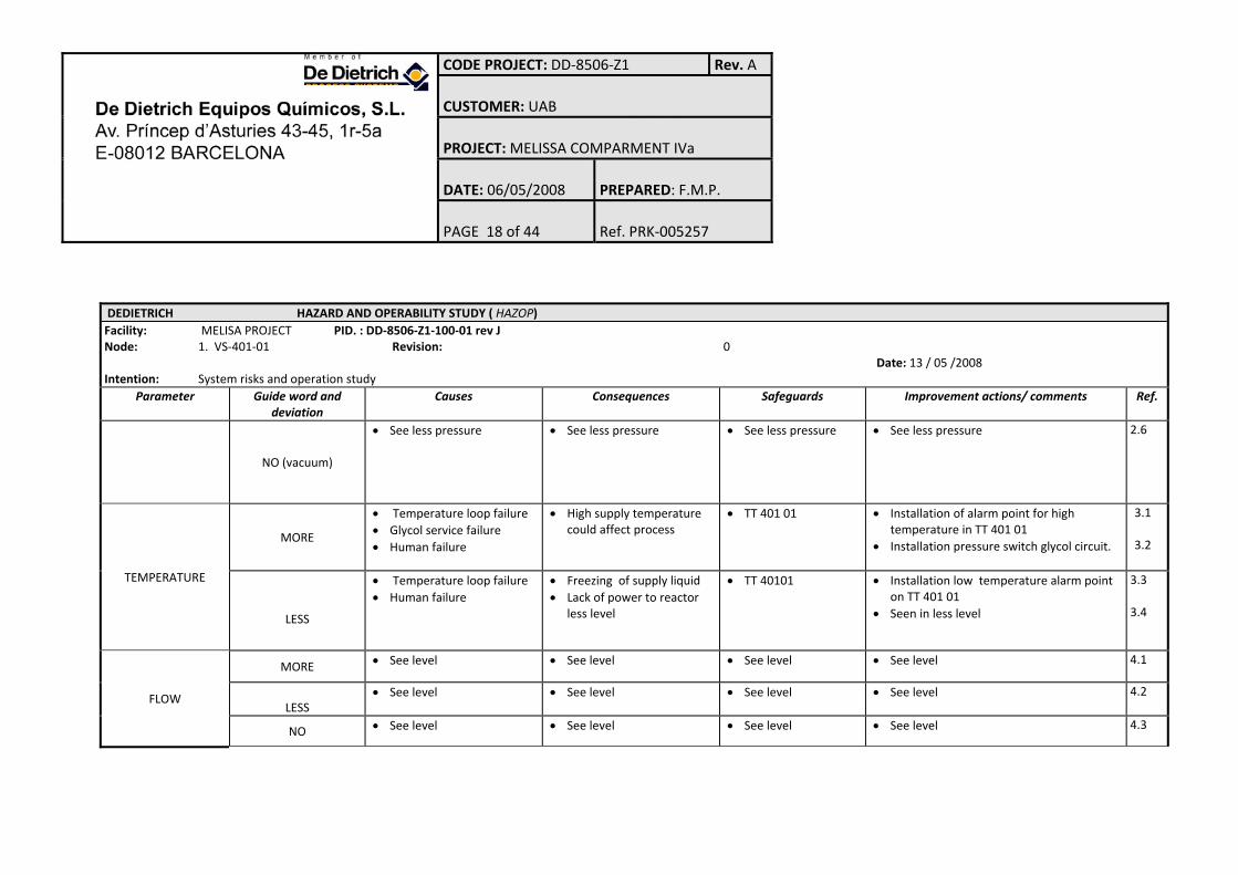
DEDIETRICH HAZARD AND OPERABILITY STUDY ( HAZOP) Facility: MELISA PROJECT PID. : DD‐8506‐Z1‐100‐01 rev J Node: 1. VS‐401‐01 Revision: 0 Date: 13 / 05 /2008 Intention: System risks and operation study
Parameter Guide word and deviation
s actions/ comments Ref. Causes
Consequence
Safeguards
Improvement
NO (vacuum)
• See less pressure • See less pressure • See less pressure • See less pressure 2.6
TEMPERATURE
MORE
• Temperature loop failure • Glycol service failure • Human failure
• High supply temperature could affect process
• TT 401 01 • Installation of alarm point for high temperature in TT 401 01
• Installation pressure switch glycol circuit.
3.1 3.2
LESS
• Temperature loop failure • Human failure
• Freezing of supply liquid • Lack of power to reactor
less level
• TT 40101 • Installation low temperature alarm point on TT 401 01
• Seen in less level
3.3 3.4
FLOW
MORE • See level • See level • See level • See level 4.1
LESS
• See level • See level • See level • See level 4.2
NO • See level • See level • See level • See level 4.3
CODE PROJECT: DD‐8506‐Z1 Rev. A CUSTOMER: UAB PROJECT: MELISSA COMPARMENT IVa DATE: 06/05/2008
PREPARED: F.M.P.
PAGE 19 of 44
Ref. PRK‐005257
DEDIETRICH HAZARD AND OPERABILITY STUDY ( HAZOP) Facility: MELISA PROJECT PID. : DD‐8506‐Z1‐100‐01 rev J Node: 1. VS‐401‐01 Revision: 0 Date: 13 / 05 /2008 Intention: System risks and operation study
Parameter Guide word and deviation
Consequences Safeguards
Improvement actions/ comments Ref. Causes
OPPOSITE • Cannot occur 4.4
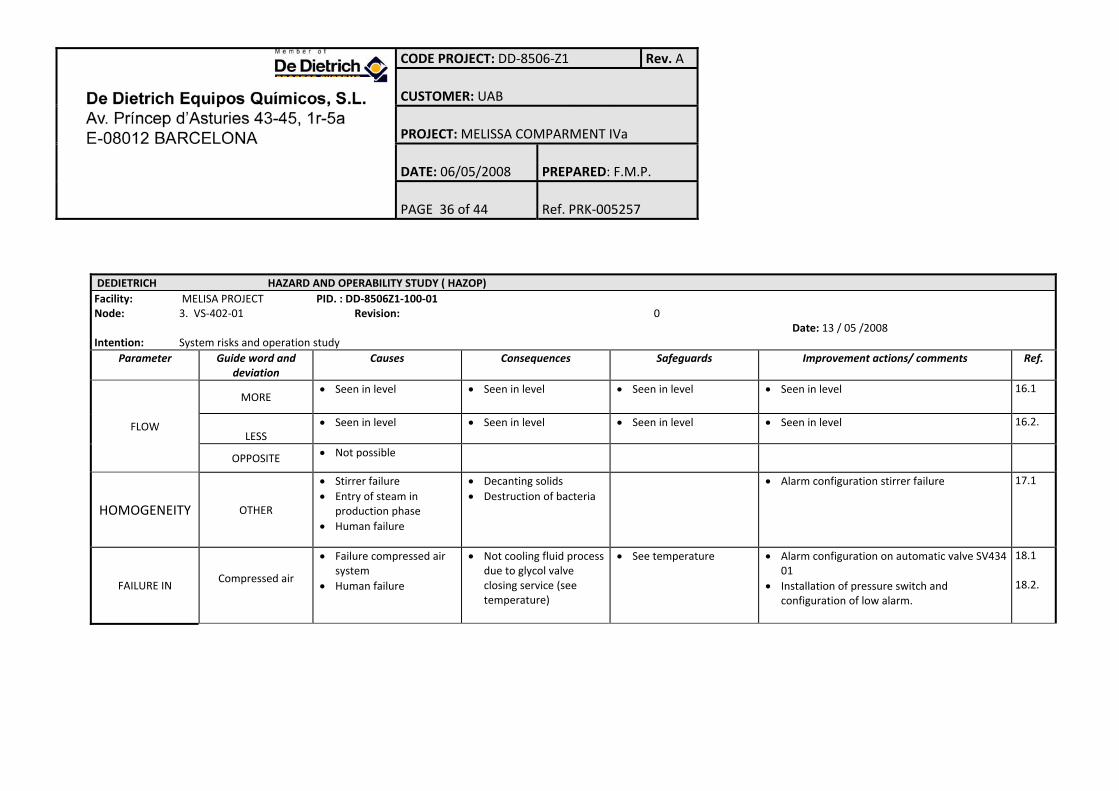
HOMOGENEITY OTHER
• Stirrer failure • entry of steam in
production phase • Human failure
• Supply not uniform • Alarm configuration stirrer failure
5.1
FAILURE IN
COMPRESSED AIR
• Failure compressed air system
• Human failure
• No cooling of process liquid due to closing glycol valve service (see temperature)
• See temperature • .Alarm configuration on automatic valve SV434 01
• Installation of pressure switch and configuration of low alarm.
5.2 5.3
ELECTRICITY
• Power cut • Human failure
• Stirrer stops and deactivation control loops
• UPS facilities for control system
5.4
STEAM
• Failure steam generation system
• Human failure
• Sterilization impossible
CODE PROJECT: DD‐8506‐Z1 Rev. A CUSTOMER: UAB PROJECT: MELISSA COMPARMENT IVa DATE: 06/05/2008
PREPARED: F.M.P.
PAGE 20 of 44
Ref. PRK‐005257
DEDIETRICH HAZARD AND OPERABILITY STUDY ( HAZOP) Facility: MELISA PROJECT PID. : DD‐8506‐Z1‐100‐01 rev J Node: 1. VS‐401‐01 Revision: 0 Date: 13 / 05 /2008 Intention: System risks and operation study
Parameter Guide word and deviation
ces s Ref. Causes
Consequen
Safeguards
Improvement actions/ comment
GLYCOL
• Failure Glycol system • Human failure
• See air system • See temperature • Installation of pressure switch and configuration of low alarm.
5.5
DEDIETRICH HAZARD AND OPERABILITY STUDY ( HAZOP) Facility: MELISA PROJECT PID. : DD‐8506Z1‐100‐01 Node: 2. RCIVa Revision: 0 Date: 13 / 05 /2008 Intention: System risks and operation study
Parameter Guide word and deviation
Causes
Consequences
Safeguards
Improvement actions/ comments Ref.
LEVEL
MORE
• Disconnection of weigh cell• Weigh cells measurement
error • Loop failure on pump
outlet
• Flooding of the reactor and the gas outlet.
• Weigh scale disconnection alarm
• Maximum level detector installation and configuration of high‐level alarm
6.1
CODE PROJECT: DD‐8506‐Z1 Rev. A CUSTOMER: UAB PROJECT: MELISSA COMPARMENT IVa DATE: 06/05/2008
PREPARED: F.M.P.
PAGE 21 of 44
Ref. PRK‐005257
DEDIETRICH HAZARD AND OPERABILITY STUDY ( HAZOP) Facility: MELISA PROJECT PID. : DD‐8506Z1‐100‐01 Node: 2. RCIVa Revision: 0 Date: 13 / 05 /2008 Intention: System risks and operation study
Parameter Guide word and deviation
Consequences
Safeguards
Improvement actions/ comments Ref. Causes
• Output pump failure • Changes in bulk density of
the liquid in the reactor • Human failure
LESS
• Disconnection of weigh cell• Error in measuring weigh
cells. • Loop failure on pump
outlet • Leak in the reactor • Changes in bulk density of
the liquid in the reactor • Human failure
• Possible changes in the overall mass balance.
• Potential air release by discharge pumps
• Weigh cells disconnection alarm
CODE PROJECT: DD‐8506‐Z1 Rev. A CUSTOMER: UAB PROJECT: MELISSA COMPARMENT IVa DATE: 06/05/2008
PREPARED: F.M.P.
PAGE 22 of 44
Ref. PRK‐005257
DEDIETRICH HAZARD AND OPERABILITY STUDY ( HAZOP) Facility: MELISA PROJECT PID. : DD‐8506Z1‐100‐01 Node: 2. RCIVa Revision: 0 Date: 13 / 05 /2008 Intention: System risks and operation study
Parameter Guide word and deviation
Ref. Causes
Consequences
Safeguard
s Improvement actions/ comments
PRESSURE
MORE
• Clogging of the output filters GF 404 01/03
• Pressure control loop failure
• Excessive pressure on process gas input
• Accidental entry of steam during the process
• Human failure
• Overpressure in the equipment ( rupture disc action)
• Air entry (through the rupture disc)
• Rupture disc • Configuration of
alarms on the 2 pressure transmitters (redundant) PI 407 01/02
• Incorporation of maximum switch PI 403 02
• Conduct discharge of rupture disc to safe collection area for people and facilities.
7.1 7.2
LESS
• Gas output control loop failure
• Human failure
• Without consequences
NO (vacuum)
• Formation of vacuum after sterilization
• Human failure
• Entry of air through the output circuit, reactor pollution(reverse flow)
• Automatic valve setting FQRC 404 01/02
7.3
CODE PROJECT: DD‐8506‐Z1 Rev. A CUSTOMER: UAB PROJECT: MELISSA COMPARMENT IVa DATE: 06/05/2008
PREPARED: F.M.P.
PAGE 23 of 44
Ref. PRK‐005257
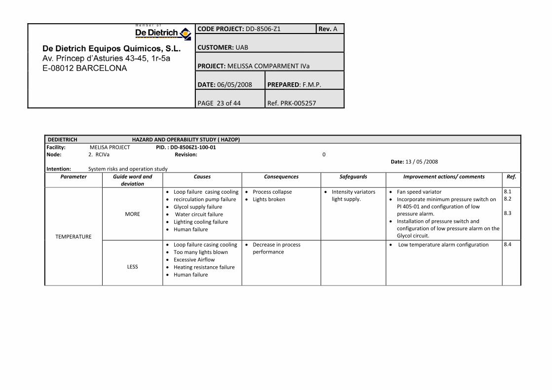
DEDIETRICH HAZARD AND OPERABILITY STUDY ( HAZOP) Facility: MELISA PROJECT PID. : DD‐8506Z1‐100‐01 Node: 2. RCIVa Revision: 0 Date: 13 / 05 /2008 Intention: System risks and operation study