UNCLASSIFIED AD NUMBER AD867664 NEW LIMITATION CHANGE TO Approved for public release, distribution unlimited FROM Distribution authorized to U.S. Gov't. agencies and their contractors; Critical Technology; APR 1970. Other requests shall be referred to Air Force Aero Propulsion Lab., Aerospace Power Div. [API], Wright-Patterson AFB, OH 45433. AUTHORITY Air Force Aero Propulsion Lab ltr dtd 12 Apr 1972 THIS PAGE IS UNCLASSIFIED
Transcript
UNCLASSIFIED
AD NUMBER
AD867664
NEW LIMITATION CHANGE
TOApproved for public release, distributionunlimited
FROMDistribution authorized to U.S. Gov't.agencies and their contractors; CriticalTechnology; APR 1970. Other requests shallbe referred to Air Force Aero PropulsionLab., Aerospace Power Div. [API],Wright-Patterson AFB, OH 45433.
AUTHORITY
Air Force Aero Propulsion Lab ltr dtd 12Apr 1972
THIS PAGE IS UNCLASSIFIED
ITERIM TECHNICAL REPORT MO. 5
on
30Dm 0RPM VANE-PUMP DEMONSTRATION
D. L. TheosJ. P. Dechow
R. K. Catters..
BATTELLE MEMORIAL INSTITUTEColumbus Laboratories
April 15, 1970
Contract No. F33615-69-C.1302Project No. 3145
Period: January I to March 31, 1970
This documn 'is subject to special export controls and eachtrasm~ittal to foreign governments or foreign nationals may hemaode only with prior approval of the Aerospace Power Division(API), Air Force Aae Propulsion Laboratory, Wright-PettersonAir Force Bsue, Ohio 4543.
AMR FORCE £130 P LSO LABORATORY EcANR FORCEI SYSTOU COM*Io PR I
MSNT-PATTURMO AIR FORCE SASS. OHIO
~"-=N "r" E
INTERIM TECHNICAL REPORT NO. 5
i' on
30, 000-RPM VANE-PUMP DEMONSTRATION
D. L. Thomas, J. P. Dechow,
R. K. Catterson, et al.
Contract No. F33615-69-C-1302Project No. 3145
I Period: January I to March 31, 1970
This document is subject to special export controls andeach transmittal to foreign governments or foreignnationals may be made only with prior approval of theAerospace Power Division (API), Air Force AeroPropulsion Laboratory, Wright-Patterson Air ForceBase, Ohio 45433.
.,.+. + .+ -.:4
I
FOREWORD
This report was prepared by the Columbus Laboratories, BattelleMemorial Institute, 505 King Avenue, Columbus, Ohio 43201 underUSAF Contract No. F33615-69-C-1302, Project No. 3145. TheBattelle project number was G-9230. Administration was under theAir Force Aero Propulsion Laboratory, Air Force Systems Command,Wright-Patterson Air Force Base, with Mr. K. E. Binns (APIE-1)
acting as project monitor.
The program is being conducted with Mr. D. L. Thomas as prin-cipal investigator. Mr. R. K. Catterson is the Division Chief in over-all charge of the program. Other members of the professional staff wtwmade significant contributions during the conduct of the project areMr. T. P. Dechow, Mr. J. T. Herridge, Mr. H. T. Johnson,Mr. R. K. Mitchell, and Dr. J. P. Wilcox.
This report, which was submitted April 15, 1970, covers workconducted during the period of January I to March 31, 1970. OtherInterim Technical Reports published on this contract are identifiedbelow:
1. T.R. Number Period DDC Number
I December 16, 1968, to March 31, 1969 AD 850538
2 April 1 to June 30, 1969 AD 854813
3 July 1 to September 31, 1969 AD 860188
4 October 1 to December 31, 1969 AD 863762
This report is being published and distributed prior to Air Forcereview. The publication of this report, therefore, does not constituteapproval by the Air Force of the findings or conclusions containedherein. It is published for the exchange and stimulation of ideas.
iii
, 1k
ABSTRACT
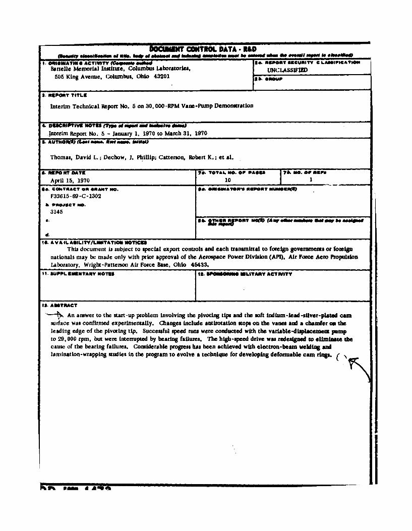
Ar answer to the start-up problem involving the pivoting tips andthe soft indium-lead-silver-plated cam surface was confirmed experi-mcntal!',. Changen include antirotation stops on the vanes and achamfer on the leading edge of the pivoting tip. Successful speed runswere conducted with the variable-displacement pump to 29, 000 rpm,but were interrupted by bearing failures. The high-speed drive wasredesigned to eliminate the cause of the bearing failures. Considerableprogress has been achieved with electron-beam welding and lamination-wrapping studies in the program to evolve a technique for developingdeformable cam rings.
IThis abstract is subject to special export controls and each
transmittal to foreign governments or foreign nationals may bemade only with prior approval of the Aerospace Power Division(API), Air Force Aero Propulsion Laboratory, Wright-PattersonAir Force Base, Ohio 45433.
This project is the continuation of the effort previously con-
ducted under Contract AF33(6 15)-2723 for the investigation of a
30, 000-rpm turbine-driven hydraulic pump. (1) During that projecta vane pump was selected as the leading concept and preliminary
experimental evaluations showed it to be very promising.
The purpose of the present project is to demonstrate the capa-bility of the pump concept to meet future aircraft requirements. Thespecific objective is to demonstrate a variable-delivery pressure-compensated vane pump with the following characteristics:
Rated Speed 30, 000 rpm
Rated Discharge Pressure 4000 psi
Rated Inlet Pressure 125 psi
Rated Delivery 50 gpm.°
Rated Temperature at outlet, 275 F, maximumcase drain, or intermediatepoint with 220 F at inlet
Efficiency at Rated Conditions 80 percent
Hydraulic Fluid MIL-H-5606B
Weight Not restricted at present -eventual goal is 15 lb
Rated Endurance 1000 hr with no maintenance
Major project tasks are:
(1) Evaluate basic pump concepts to meet the design requirements
(2) Experimentally qualify components such as vanes and variable-displacement mechanisms
(3) Evaluate a fixed-displacement model of the pump
(4) Design and fabricate a pressure-compensator control for thevariable -displacement pump
(1) Thomas. D. L, at at., lnvestigatlon of a 30. 000-"p Tuzblns-pfd Hydraulc Pump.AFAPL-H -5. AD S4312, by knell. MeMorl IDmtit (AM. 196).
I
, ., . . -,., .,•
... . :;-., ..
" • ' : , :," i, , . = r I
Nt~y
* (5) Evaluate the variable-displacement pump at the design conditions
* (6) Perform a 1000-hour endurance run.
The basic vane-pump concept selected for development has alaminated, deformable cam ring for varying displacement and pivoting-
tip vanes that are hydrodynamically supported for high-speed operation.A computer analysis of the pivoting tips has been conducted and theyhave been experimentally qualified at the design conditions. Variouscam-ring materials have been investigated in wear and fatigue tests.
The fixed-displacement model pump has been designed and fabricatedand evaluation has begun. A computer analysis of the pressure corn-pensator has been completed. A program for evolving a deformaLlecam-ring fabrication technique and for providing cam rings for p mpevaluation is being conducted.
' 'v ZI
2
SECTION II
TECHNICAL INVESTIGATION
1. FIXED-DISPLACEMENT PUMP
a. Start-Up Problem
The start-up problem, discussed in Interim Technical ReportNo. 4, was investigated experimentally. The problem was revealedwhen a failuirc occurred seconds after start-up and before pump speedreached 2500 rpm. The pump had two vanes with tungsten-carbidepivoting tips and a one-half-displacement cam ring. One tip left itssocket and was broken in many pieces, resulting in damage to the otherparts.
The start-up problem apparently occurred because the sharpleading edge of a tip contacted the cam ring and dug in. The vane andtip vibrated radially, chattering against the soft indium-lead-siiver-plated cam ring until a sufficiently high tangential 'orce dragged thetip from the vane socket.
Two changes were made to correct this problem. A smallchamfer was ground on the leading edge of the pivoting tip so it couldcontact the cam ring only with a smooth sloping surface. Stops wereadded to the vane to limit tip rotation. This ensured that radial vaneforce could overcome cam-surface frictional drag and allow the tipto pivot to its proper orientation with the cam surface. The stops werebrass shim stock soldered in place and then machined.
The changes were evaluated experimentally using a solid camring with the circular indium-lead-silver-plated bore sufficientlyeccentric to cause full vane stroking. Six starts were made with onepivoting-tip vane and seven starts were made with two pivoting-tipvanes. The initial position for the last ten starts was with the tipsrotated backward so they would contact the cam ring with their leadingedge. Thus the tip was forced to rotate in a direction counter to thefrictional drag of the cam ring to achieve the proper orientation withthe cam-ring surface. In the last nine starts, the vane was positionedradially inward at the bottom of its rotor slot. The cam ring wasexamined after each starting sequence. No distress was observed inany of the tests.
3
17.
A new set of pivoting -tip vanes that have integral vane stops andchamfered pivoting tips were ordered. The met of tips was received
late in March and the set of vanes is expected early in April.
b. Vane Cocking
Vane cocking in the radial direction, wherein diagonally oppositecorners of a vane could jam between the end plates at start-up, is apotential problem. The possibility of jamming does not exist for vaneend clearances greater than approximately 0. 0043 inch because the rotorand cam ring limit radial motion. In four of the start-up experimentswith two vanes described above, tht. vane end clearance was less than0.0043 inch and as little as 0.0026 inch. No difficulty with vane jam-ming was noted.
c. Speed Runs
Speed runs were conducted using an indium-lead-silver-platedcircular-bore eccentric cam ring, reworked vanes and tips, and essen-tially room-temperature hydraulic fluid. In a series of runs, sixvanes were tested to approximately 29,000 rpm. At this speed a fail-are occurred in which the shaft-end pump bearing and the out-boarddrive bearing overhzeated.
The leading pivoting-tip vane stop was completely missing onone vane, partially missing on two vanes, and damaged slightly onthe other three. The pivoting tips were unchanged. The cam surfaceshowed some marks that were attributed to loss of the vane stops butshowed no distress caused by speed or load. It is assumed that cen-triftgal force and/or fluid-inertial forces were great enough to causethe loss of one, perhaps insecurely soldered, vane stop, which thencaused the other damage. As the new set of vanes will have integralvane stops, it was decided to not resume tests until they are available.
The speed tests were interrupted by several bearing failureswhich were due to high radial loads caused by the first critical speedfor the pumnp-shaft drive-coupling arrangement. Subsequent to twoseccesful rotor-only checkout runs to 30, 000 rpm, the shaft-endnUmp bearing overheated while increasing speed to approximately17, 500 rpm. It was calculated that the first critical speed for thepam-salmt drive-coupling arrangement was less than 21,000 rpm.The drive coupling touched the magnetic speed pickup in a mannerwhich indicated excessive deflection in a selected rotational orienta-tWon whic'h confirmed that critical speed was the problem.
4
An outboard bearing was added to support the shaft coupling andpreclude excessive deflection. The first outboard bearing tried hadinsufficient area and was inadequately lubricated. The second out-
board bearing worked satisfactorily until it and the pump shaft-endbearing overheated at approximately 29, 000 rpm, as discusbed above.
The cause of this failure was not clear. Shredded materialfrom the brass vane-stop could have passed through the pump shaft-end bearing in sufficient quantity to cause it to overheat. "his couldhave caused sufficient shaft distortion and load to cause the outboardbearing to overheat. The other possibility was that the independentmounting of the pump and speed increaser by brackets from a commonframe was inadequate for the precise alignment necessary. Thir. drivearrangement was successfully used in the previous project, but, there,the pump shaft had a much higher natural frequency.
It was decided to mount the pump directly on the speed increaserin future rurs. This will eliminate alignment problems, eliminate theoutboard bearing, and increase the combined pump shaft-couplingcritical speed to above 40, 000 rpm. The new drive is completed andwill be installed and tested early in April.
Solid cam rings having the cam-ground profiles of the one-half-and ±ull-displacement cam rings are now ready for evaluation.
A center housing for evaluating a manually controlled deformablecam ring has been fabricated and is ready for use.
Z. DEFORMABLE CAM RING
a. Electron-Beam Welding Studies
Dur~ng this period electron-bean welding studies were continuedusing solid cylinders which simulated the shape of the deformable camring but which did not have laminations. The purpose of the studies wasto investigate possible means to limit the porosity and distortion intro-duced during welkmg. These investigations were completed during thisperiod.
Previous efforts with electron-beam welding were nade usinghollow nested cylinders. These cylinders exhibited severe shrinkageproblems, with the ID and OD at the axial center shrinking severalmils more than the corresponding ID's and OD's at the edges.
5
Cylinders with stepped bores (small bore in the axial center with largerbores at the edges) were fabricated to increase the stiffness in the centerand counteract the welding-shrinkage pattern. These stepped-borecylinders reduced the bellmnouthing problem, however, they still exhib-ited essentially the same distortion characteristics as a solid cylinder.Since the solid cylinder was easier to fabricate than the stepped-borecylinder, a solid mandrel was chosen for the deformable cam ring.
During these welding studies, it was found that the electron-beamweld profile varied as the temperature of the part being welded changed.As the temperature increased during welding, the weld depth decreasedand the weld width increased. To eliminate changes in weld profiles dueto this cause, the feasibility of maintaining the interior temperature ofthe part at a nearly constant temperature was investigated.
Sample cylinders were preheated using a defocused, low-currentelectron beam to 300, 400, 500, 600, 700 and 800 F in the weldingchamber and were electron-beam welded at these temperatures. Poros-ity and distortion in the different samples preheated to the temperatureof 500 F and above was less than those at lower temperatures. The
interior temperature during welding was maintained at the preheattemperature by adjusting the electron-beam welding rate so that theheat loss from the part to the welder chamber equaled the heat gainfrom the electron-beam during welding passes. The interior tempera-ture of the part being welded was continuously monitored with thermo-couples whose leads went through the electron-beam welding chamberwalls to a strip-chart recorder. 600 * 20 F was selected as the pre-heat and welding temperature for welding the deformable camn ring.
A final investigation was made to determine the distortion andporosity effects on the cylinder from two, three, and six axial weldsin a lap space. It was previously observed that the out-of-roundcondition was more severe at the OD where the electron-beam weldhad a "nail head" than at interior diameters where the electron-beamwas narrower and there was surrounding material to somewhat balancethe shrinkage direction. In this study, it was found that twelve axialwelds, three each in four lap-space-size areas spaced at 90-degreeintervals on the sample cylinder, gave an out-of-round condition of0. 002 inch on R at the OD, and an axial straightness to within0. 0003 inch at the OD. These conditions were judged to be compati-ble with the desired tolerances for the deformable cam, ring. Thesample cylinder with six axial welds placed in a lap-space-size areahad distortion that was thought to be marginal for the deformable camring.
6
~,.. -..
Summary of Welding Studies. Methods that were successfullyused to reduce porosity and distortion are:
" Increasing the part stiffness
" Preheating the part prior to welding
" Maintaining the interior of the part at the preheattemperature during welding
• Reducing the electron-beam energy irsput by limitingthe depth, width, and number of welds.
b. Wrapping and Fabricating Studies
As stated in Interim Technical Report No. 4, the first sampledeformable cam ring was fabricated using a mandrel with an0. 008-inch-deep spot-face profile placed in the mandrel in a lap-space-block location. An 0. 008-inch-thick strip was fitted into this spot-face profile and inert-gas arc welded to the mandrel. The strip wasthen continuously wound on the mandrel using a low-speed lathe to turnthe mandrel while a 250-pound pull was applied to the strip.
During this report period the above sample ring was electron-beam welded. The cam ring had six overlapping axial electron-beamwelds placed in the area containing the spot face in the mandrel. Thiswelded the transition zone from one lamination to the next into a solidblock, while all other elements of the cam-ring laminations outsidethis transition zone were continuous circular arcs. To maintain thestraightness of axial elements of the cam ring after welding, sixcounter-balancing axial welds were placed at 180 degrees to thespot-face profile. With all of the above welding as well as the re-quired axial welds in the other lap space block areas and circunferen-tial welds at the ends of the cam ring, the distortion was greater thandesired even using the above-mentioned preheating techniques, etc.Out-of-round conditions on the OD of the sample ring were measuredat about 0. 004 inch on R. Some porosity of the electron-beam weldsin the spot-face-profile area was also found. Because of the distor-tion and porosity, efforts on this type of cam ring were discontinued.
Another method of fabricating the deformable cam ring was in-vestigated, in which a round mandrel was used. The strip stock wasinert-gas arc welded to the round mandrel and then continuouslywrapped with 250 pounds pull on the strip. With this technique, atriangular-shaped gap occurs at the transition of the first wrap to the
.7
J , : ,;; C, - . .. . . ..
second wrap in a lap-space area. After the electron-beam welding,etc., the mandrel will be removed and this triangular-shaped regionwill be plated with silver when the cam-ring bore is plated.
Currently three deformable cam rings are being fabricated perthis second method. After the wrapping on the round mandrel men-tioned above, the first deformable cam ring (SN-1) had three initialaxial welds placed in each lap space and one circumferential weldput in each end of the cam ring. These welds were put only throughthe lamination stack and into the mandrel. No outer ring was used,and the electron beam had to penetrate only the lamination stack andinto the mandrel. Since no solid ring was located over the lamina-tions, there was less cross section to weld through. This permittedthe minimum energy input and the minimum weld depth, i.e. , just
F through the lamination stack. The OD of the electron-beam weldswere ground down to the OD lamination surface and an outer ring,
Kfrom which the lap space blocks are to be fabricated, was heatshrunk onto the lamination stack. This outer ring was relieved(using a milling operation) in the areas where the axial welds defin-ing the lap-space-block edges were placed. These cut-out or re-lieved areas provided a reduction in the cross section that thesecond electron-beam welds must penetrate. SN-I has been heattreated and is presently being faced down to length. It will then havethe lap space blocks ground to size.
For the second deformable cam ring (SN-2) being fabricated,the number of electron-beam welds was reduced. Only one axial weld(instead of three as for SN-I) was put in each lap space. The axialwelds, one in the approximate center of each lap space, and two cir-cumferential welds, one on each end of the cam ring, were put onlythrough the lamination stack, as before. Some porosity was foundin the exterior surface of the axial weld in the lap space with the tri-angular gap at the mandrel/lamination interface. It appears thatart of the electron-beam weld penetrated through this gap. A second
welding pass was made which eliminated the exterior porosity. How-ever, the extent of porosity remaining deeper in the weld cannot bedetermined until the center mandrel is removed. This cam ring nowhas the lap-apace-block ring (with areas relieved for electron beamwelding) heat shrunk on the lamination stack. The electron-beamwelds, defining the edges of the lap-space blocks, will now be put inthrough the edge of the blocks, through the lamination stack, and intothe mandrel.
A third deformabte cam ring (SN-3) has been started. The pro-ceasing of this cam ring will be essentially the same as for SN-2
8
4L',.
except that the center electron-beam weld in the iap space with thetriangular gap will be offset by the amount necessary to miss theedge of the gap. It is thought that this will eliminate the weld poros-ity found in SN-2. This cam ring is now ready for the first electron-beam wcding.
3. VARIABLE-DISPLACEMENT PUMP
Decisions regarding the configuration of the variable-displacement pump have been made. It will have all of the rotatingparts required in flight hardware (including shaft seals, bearings,etc.), but it will not be designed for minimum weight. It will bedesigned to fit the accessory pad on an auxiliary power unit fordemonstration purposes. The design will reasonably simulateflighL hardware, but its experimental nature will not be compromisedand it will be instrumented as fully as necessary for laboratoryevaluation.
.7'11
,I j
SECTION IU
FUTURE WORK
For the coming 3-month period, the following work is planned:
(1) Complete laboratory experiments with the fixed-displacementpump involving solid cam rings and mechanically positioneddefornmable cam rings
(2) Complete the development of a process for fabricatingdeformable cam rings
(3) Design and begin fabrication of the variable-displacementpump.
10
10,
-. . . , , _ . . . ' S , . , - •
'• " ~~~~I .. -,' . .. ."• ". ....
ROCIENTCONTROL DATA- R&Doftem" obmeeddie ofesome. "*O of a606100 -d I.A"aoti 0"G anmd ohm Be #ew#I sop is S.Beee
I!nterim Report No. 5 - January 1. 1970 to March 31. 1970I. AUTh@NjSJ (Los nme. Smi unme O
Thomas, David L.; Dechow. 1. Phillip; Catterson, Robert K.; et &I.
6. MPO PI DA TU 20 TOTAL 00.@OF PAGCES [76 me.. 61..map
Api 5 9010 1Go. C~kTRACI OR GRANT 00. 6111111111AOR41POTNUEW
3145
I0. A V A IL AGILSTY/LIUflATION NOTOCES1This document is subject to special export controls and each transmittal to foreign govemumemts or foreign
nationals may be made only with prior approval of the Aerospace Power Division (API). Air Force Aero PropulsionLaboratory. Wright -Patterson Air Force Base, Ohio 45433.
11 - SUPPL aNITART NOTES Wa SPOUN111 *LITANY ACTMTY
IS. AMTRACT
_-4,$ An answer to the start-up problem involving the pivoting tips and the soft indium -lead -silver-plated camsurface was confirmed experimentally. Changest include antimoation stoPS on the vanes And a chamfer on theleading edge of the pivoting tip. Successful speed runs were conducted with the variable-displacem pumpto 29. 000 rpm. but were interrupted by bearing failures. The high-speed drive was redeigned to eliminate thecause of the bearing failures. Considerable progress has been achieved with electron-beaim weldinig andlamination -wrapping studies in the program to evolve a technique for developing deformable cam rins.(
~ A AWf
oSacu Class cmuo1.KEY WORDSI LINK a LINK 5 1155______________________________________________________ ROLE wY ROLE %T soil