108
www.huawei.com Copyright © 2006 Huawei Technologies Co., Ltd. All rights reserved. Service Configuration of the OptiX RTN 900 V100R001 — on the T2000
| Date post: | 25-Dec-2015 |
| Category: |
Documents |
| Upload: | abu-abdullah-sameer |
| View: | 89 times |
| Download: | 14 times |
www.huawei.com
Copyright © 2006 Huawei Technologies Co., Ltd. All rights reserved.
Service Configuration of the OptiX RTN 900 V100R001
— on the T2000

Copyright © 2006 Huawei Technologies Co., Ltd. All rights reserved. Page 2
Preface
This course is developed based on the services that
can be configured on the OptiX RTN 900 V100R001.
This course aims to instruct engineers to
independently configure services on the OptiX RTN
900 V100R001.

Copyright © 2006 Huawei Technologies Co., Ltd. All rights reserved. Page 3
Guidelines on Learning
This course is organized according to the configuration
contents of the OptiX RTN 900 V100R001.
Before you study this course, it is recommended that
you have a study on the following courses: Topic on the
Control Plane of the OptiX RTN 900 V100R001, Topic
on the Packet Service of the OptiX RTN 900 V100R001,
and Packet Service Planning and Design of the OptiX
RTN 900 V100R00.
This course focuses on the configuration methods of
various services.

Copyright © 2006 Huawei Technologies Co., Ltd. All rights reserved. Page 4
References
Configuration guides contained in the
package of documents for the OptiX RTN
910 and OptiX RTN 950

Copyright © 2006 Huawei Technologies Co., Ltd. All rights reserved. Page 5
Objectives
After completing this course, you should be familiar with the
methods for configuring the following services on the OptiX
RTN 900 V100R001:
Ethernet service
CES service
ATM/IMA service

Copyright © 2006 Huawei Technologies Co., Ltd. All rights reserved. Page 6
Contents
1. Types of Services on the OptiX RTN 900
V100R001
2. Configuring the Ethernet Service
3. Configuring the CES Service
4. Configuring the ATM/IMA Service
Copyright © 2006 Huawei Technologies Co., Ltd. All rights reserved. Page 7
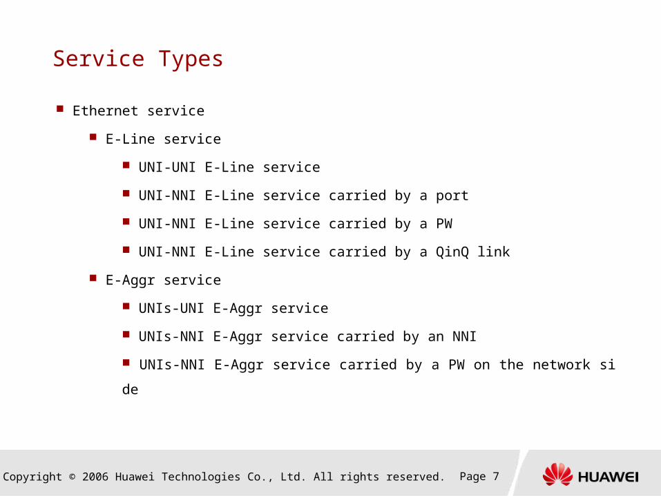
Service Types
Ethernet service
E-Line service
UNI-UNI E-Line service
UNI-NNI E-Line service carried by a port
UNI-NNI E-Line service carried by a PW
UNI-NNI E-Line service carried by a QinQ link
E-Aggr service
UNIs-UNI E-Aggr service
UNIs-NNI E-Aggr service carried by an NNI
UNIs-NNI E-Aggr service carried by a PW on the network side
Copyright © 2006 Huawei Technologies Co., Ltd. All rights reserved. Page 8
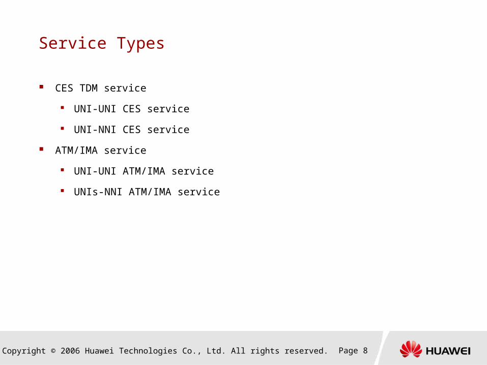
Service Types
CES TDM service
UNI-UNI CES service
UNI-NNI CES service
ATM/IMA service
UNI-UNI ATM/IMA service
UNIs-NNI ATM/IMA service
Copyright © 2006 Huawei Technologies Co., Ltd. All rights reserved. Page 9
Contents
1. Types of Services on the OptiX RTN 900
V100R001
2. Configuring the Ethernet Service
Configuration Process
Configuration Tasks
3. Configuring the CES Service
4. Configuring the ATM/IMA Service
Copyright © 2006 Huawei Technologies Co., Ltd. All rights reserved. Page 10
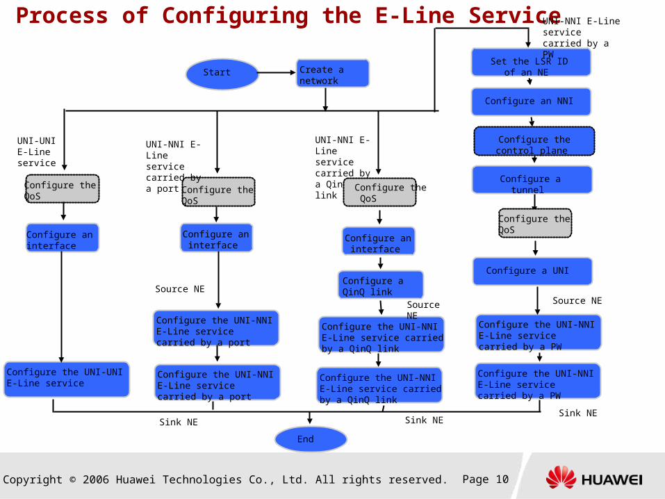
Process of Configuring the E-Line Service
Create a network
Configure the QoS
Configure an interface
Configure the UNI-UNI E-Line service
Configure the UNI-NNI E-Line service carried by a port
Configure the UNI-NNI E-Line service carried by a port
Configure an interface
Configure the QoS
Set the LSR ID of an NE
Configure the UNI-NNI E-Line service carried by a QinQ link
Configure the UNI-NNI E-Line service carried by a QinQ link
Configure an interface
Configure a QinQ link
Configure an NNI
Configure the control plane
Configure a tunnel
Configure a UNI
Configure the UNI-NNI E-Line service carried by a PW
Configure the UNI-NNI E-Line service carried by a PW
End
UNI-UNI E-Line service
UNI-NNI E-Line service carried by a port
UNI-NNI E-Line service carried by a QinQ link
UNI-NNI E-Line service carried by a PW
Source NE
Sink NE
Source NE
Sink NE
Source NE
Sink NE
Configure the QoS
Configure the QoS
Start

Copyright © 2006 Huawei Technologies Co., Ltd. All rights reserved. Page 11
Process of Configuring the E-Aggr Service
Start
Create a network
Configure the UNIs-UNI E-Aggr service
Configure the UNIs-NNI E-Aggr service carried by a port
Configure the NNIs-UNI E-Aggr service carried by a port
Configure an interface
Configure the QoS
Configure the control plane
Create a tunnel
Configure the NNIs-UNI E-Aggr service carried by a PW
Configure the UNIs-NNI E-Aggr service carried by a PW
End
UNIs-UNI E-Aggr service
UNIs-NNI E-Aggr service carried by a port
End
End
UNIs-NNI E-Aggr service carried by a PW
Copyright © 2006 Huawei Technologies Co., Ltd. All rights reserved. Page 12
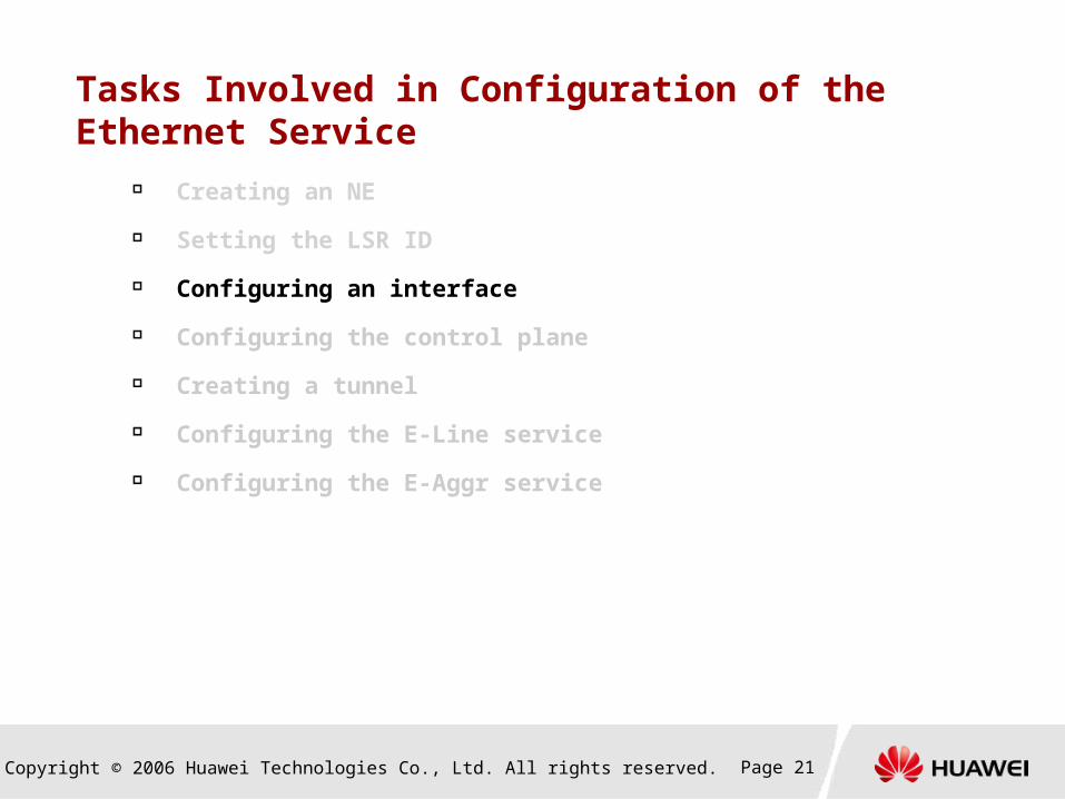
Tasks Involved in Configuration of the Ethernet Service
Creating an NE
Setting the LSR ID
Configuring an interface
Configuring the control plane
Creating a tunnel
Configuring the E-Line service
Configuring the E-Aggr service
Copyright © 2006 Huawei Technologies Co., Ltd. All rights reserved. Page 13
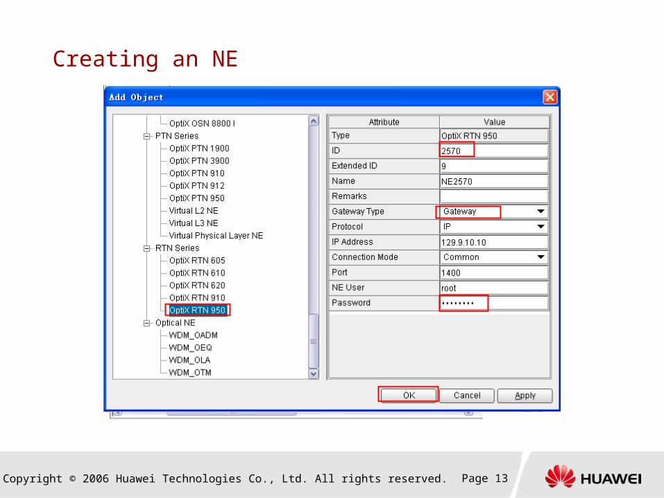
Creating an NE
Copyright © 2006 Huawei Technologies Co., Ltd. All rights reserved. Page 14
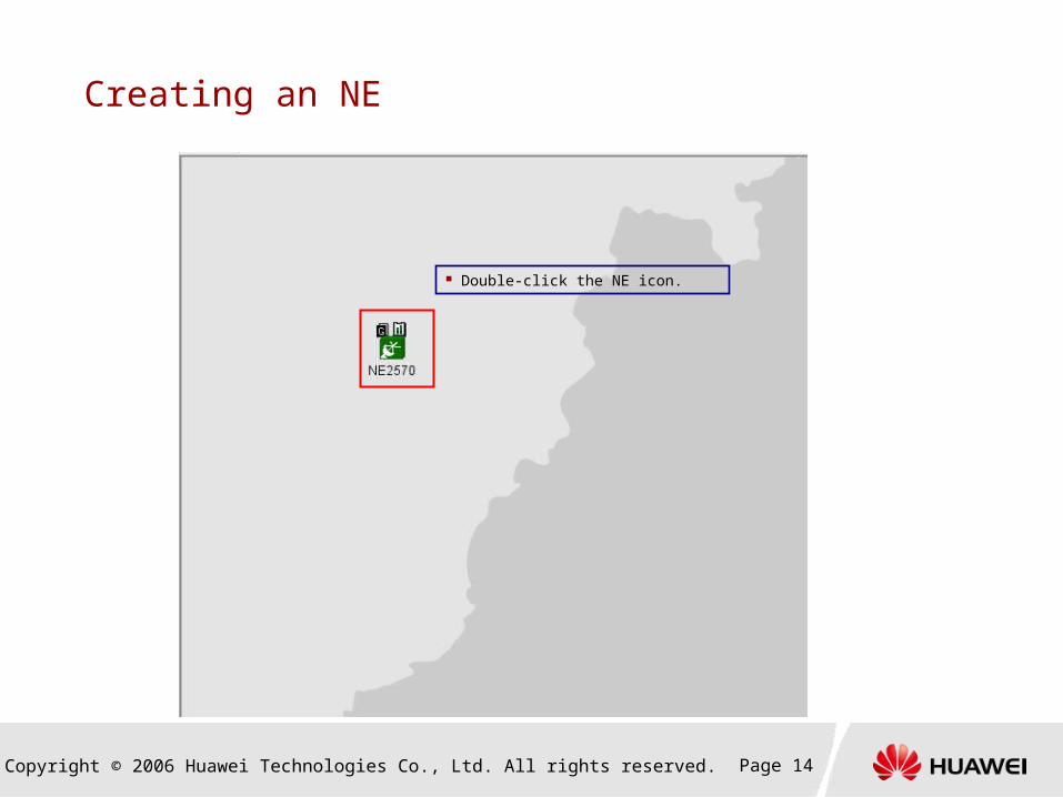
Creating an NE
Double-click the NE icon.
Copyright © 2006 Huawei Technologies Co., Ltd. All rights reserved. Page 15
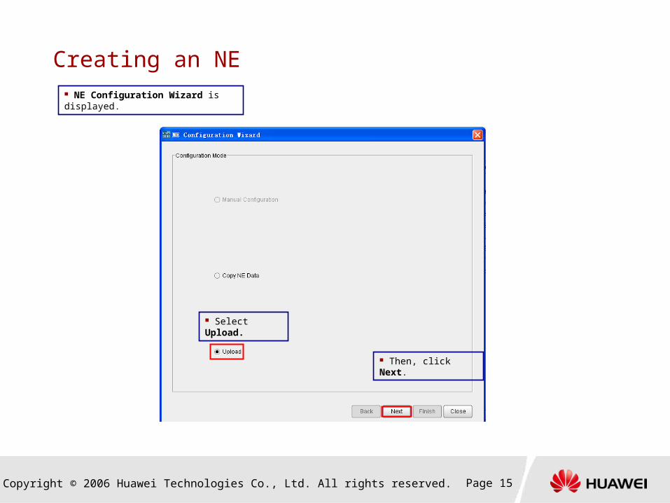
Creating an NE
NE Configuration Wizard is displayed.
Select Upload.
Then, click Next.
Copyright © 2006 Huawei Technologies Co., Ltd. All rights reserved. Page 16
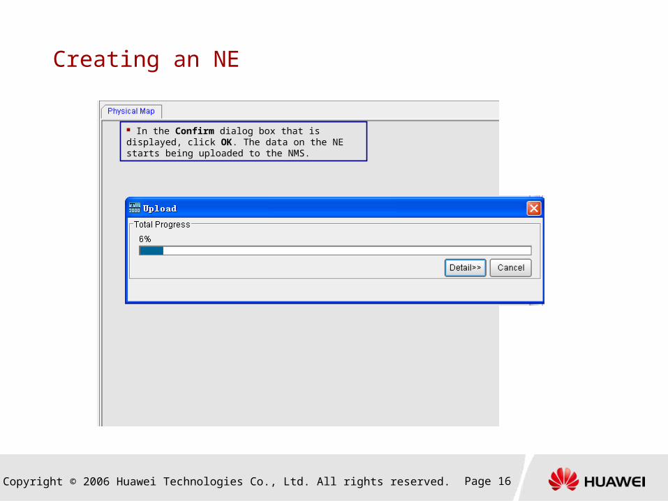
Creating an NE
In the Confirm dialog box that is displayed, click OK. The data on the NE starts being uploaded to the NMS.
Copyright © 2006 Huawei Technologies Co., Ltd. All rights reserved. Page 17
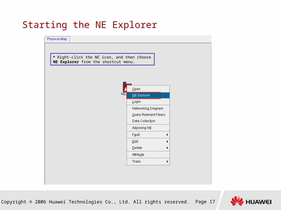
Starting the NE Explorer
Right-click the NE icon, and then choose NE Explorer from the shortcut menu.

Copyright © 2006 Huawei Technologies Co., Ltd. All rights reserved. Page 18
Starting the NE Explorer
NE Explorer is displayed.
Copyright © 2006 Huawei Technologies Co., Ltd. All rights reserved. Page 19
Tasks Involved in Configuration of the Ethernet Service
Creating an NE
Setting the LSR ID
Configuring an interface
Configuring the control plane
Creating a tunnel
Configuring the E-Line service
Configuring the E-Aggr service
Copyright © 2006 Huawei Technologies Co., Ltd. All rights reserved. Page 20
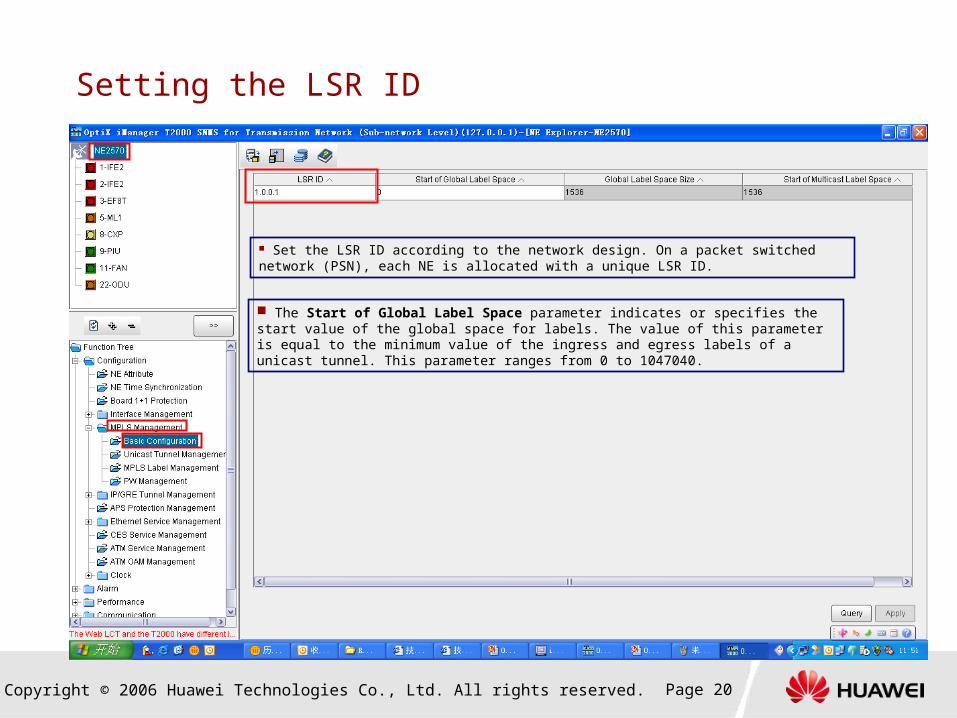
Setting the LSR ID
The Start of Global Label Space parameter indicates or specifies the start value of the global space for labels. The value of this parameter is equal to the minimum value of the ingress and egress labels of a unicast tunnel. This parameter ranges from 0 to 1047040.
Set the LSR ID according to the network design. On a packet switched network (PSN), each NE is allocated with a unique LSR ID.
Copyright © 2006 Huawei Technologies Co., Ltd. All rights reserved. Page 21
Tasks Involved in Configuration of the Ethernet Service
Creating an NE
Setting the LSR ID
Configuring an interface
Configuring the control plane
Creating a tunnel
Configuring the E-Line service
Configuring the E-Aggr service

Copyright © 2006 Huawei Technologies Co., Ltd. All rights reserved. Page 22
Configuring a Radio Interface
If different attributes are set for a radio interface, the radio interface is applicable to different scenarios. For details, refer to the following
table.
Application Scenario Interface Type Required Interface Attribute
Accessing the Ethernet service Ethernet interface General attributes and Layer 2 attributes
Carrying the tunnel Ethernet interface General attributes and Layer 3 attributes
When a radio interface is used to carry the QinQ link, the configuration process is almost the same as the configuration process when
it is used to the carry the Ethernet service. The only difference is that a different encapsulation format should be selected.
On a radio transmission network, a UNI is generally a radio interface. Hence, it is required to configure the radio interface for all the
services on the radio equipment.
Configuring a radio link
Setting general
attributes
Setting Layer 2
attributes
Setting IF attributes
Setting advanced attributes
Carrying the Ethernet service
Configuring a radio link
Setting general
attributes
Setting Layer 3
attributes
Setting IF attributes
Setting advanced attributes
Carrying the tunnel
Copyright © 2006 Huawei Technologies Co., Ltd. All rights reserved. Page 23
Configuring a Radio Interface
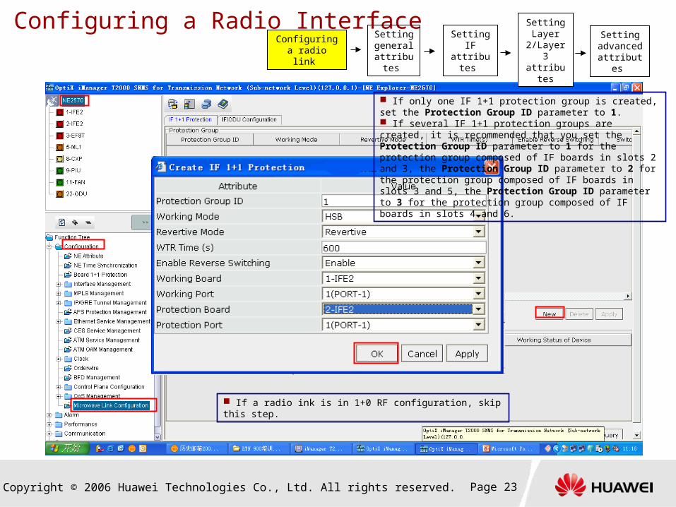
If a radio ink is in 1+0 RF configuration, skip this step.
Configuring a radio link
Setting general
attributes
Setting Layer
2/Layer 3 attributes
Setting IF attributes
Setting advanced attributes
If only one IF 1+1 protection group is created, set the Protection Group ID parameter to 1. If several IF 1+1 protection groups are created, it is recommended that you set the Protection Group ID parameter to 1 for the protection group composed of IF boards in slots 2 and 3, the Protection Group ID parameter to 2 for the protection group composed of IF boards in slots 3 and 5, the Protection Group ID parameter to 3 for the protection group composed of IF boards in slots 4 and 6.
Copyright © 2006 Huawei Technologies Co., Ltd. All rights reserved. Page 24
Configuring a Radio Interface
Configuring a radio link
Setting general
attributes
Setting Layer
2/Layer 3 attributes
Setting IF attributes
Setting advanced attributes
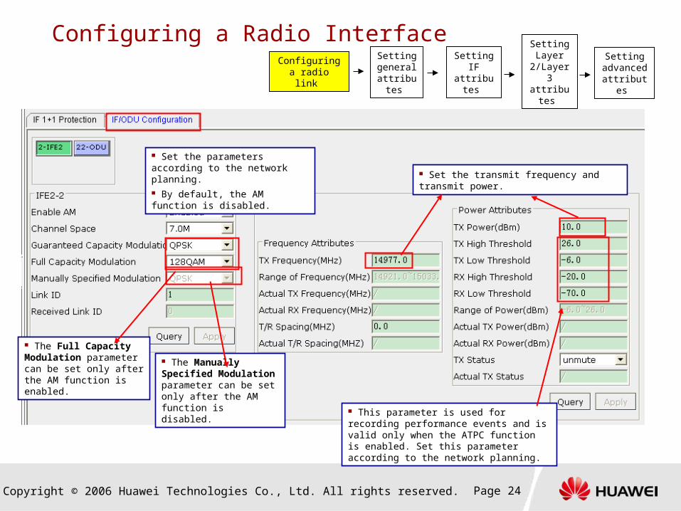
Set the transmit frequency and transmit power.
Set the parameters according to the network planning. By default, the AM function is disabled.
The Full Capacity Modulation parameter can be set only after the AM function is enabled.
The Manually Specified Modulation parameter can be set only after the AM function is disabled.
This parameter is used for recording performance events and is valid only when the ATPC function is enabled. Set this parameter according to the network planning.
Copyright © 2006 Huawei Technologies Co., Ltd. All rights reserved. Page 25
Configuring a Radio Interface Configuring a
radio link
Setting general
attributes
Setting Layer
2/Layer 3 attributes
Setting IF attributes
Setting advanced attributes
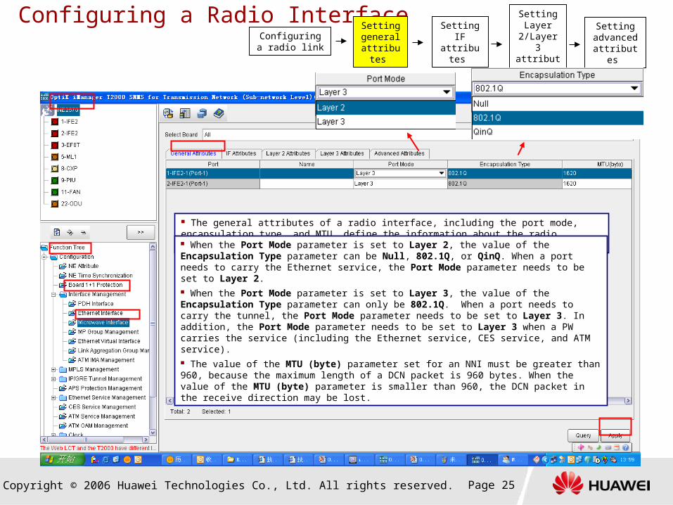
The general attributes of a radio interface, including the port mode, encapsulation type, and MTU, define the information about the radio interface at the physical layer.
When the Port Mode parameter is set to Layer 2, the value of the Encapsulation Type parameter can be Null, 802.1Q, or QinQ. When a port needs to carry the Ethernet service, the Port Mode parameter needs to be set to Layer 2. When the Port Mode parameter is set to Layer 3, the value of the Encapsulation Type parameter can only be 802.1Q. When a port needs to carry the tunnel, the Port Mode parameter needs to be set to Layer 3. In addition, the Port Mode parameter needs to be set to Layer 3 when a PW carries the service (including the Ethernet service, CES service, and ATM service). The value of the MTU (byte) parameter set for an NNI must be greater than 960, because the maximum length of a DCN packet is 960 bytes. When the value of the MTU (byte) parameter is smaller than 960, the DCN packet in the receive direction may be lost.
Copyright © 2006 Huawei Technologies Co., Ltd. All rights reserved. Page 26
Configuring a Radio Interface
Configuring a radio link
Setting general
attributes
Setting Layer
2/Layer 3 attributes
Setting IF attributes
Setting advanced attributes
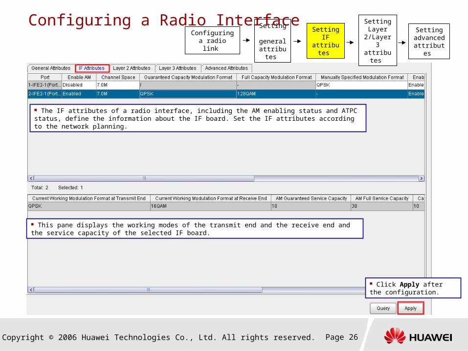
The IF attributes of a radio interface, including the AM enabling status and ATPC status, define the information about the IF board. Set the IF attributes according to the network planning.
This pane displays the working modes of the transmit end and the receive end and the service capacity of the selected IF board.
Click Apply after the configuration.
Copyright © 2006 Huawei Technologies Co., Ltd. All rights reserved. Page 27
Configuring a Radio Interface
Configuring a radio link
Setting general
attributes
Setting Layer
2/Layer 3 attributes
Setting IF attributes
Setting advanced attributes
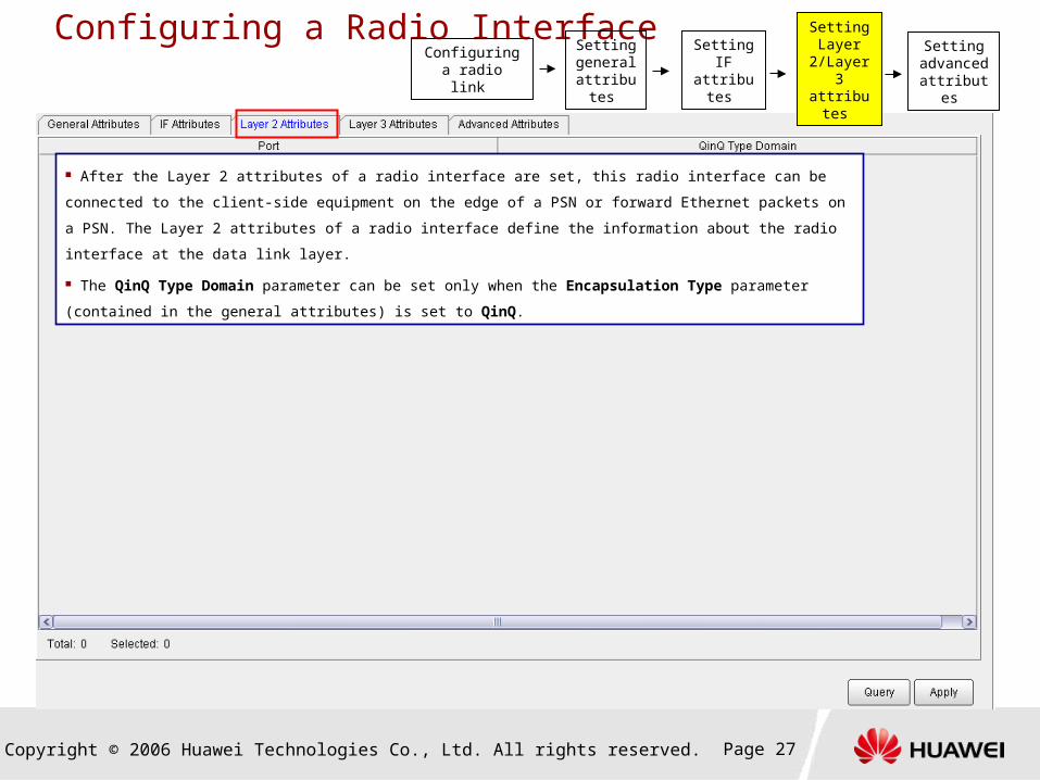
After the Layer 2 attributes of a radio interface are set, this radio interface can be connected to the client-side equipment
on the edge of a PSN or forward Ethernet packets on a PSN. The Layer 2 attributes of a radio interface define the
information about the radio interface at the data link layer.
The QinQ Type Domain parameter can be set only when the Encapsulation Type parameter (contained in the general
attributes) is set to QinQ.

Copyright © 2006 Huawei Technologies Co., Ltd. All rights reserved. Page 28
Configuring a Radio Interface
If a radio interface is used to carry the tunnel, the Layer 3 attributes of the radio interface need to be set. The Layer 3 attributes of
a radio interface define the information about the radio interface at the network layer.
Parameter description Enable Tunnel: After a tunnel is enabled, the port can identify and process the MPLS label, and thus can support the dynamic signaling and routing. Max Reserved Bandwidth (kbit/s): This parameter specifies the bandwidth used by a tunnel. The maximum reserved bandwidth should not be higher than the physical bandwidth at the port. TE Measurement: This parameter allows manual intervention in routing. When the value of this parameter is smaller, the priority of the link is higher. In this manner, traffic congestion on the shortest path, which occurs in conventional routing, can be prevented. Admin Group: This parameter specifies the link attribute. After the affinity attribute of a dynamic tunnel is set, it compares its affinity attribute with the admin group attribute of links in the case of link selection. In this manner, the dynamic tunnel can determine which links should be selected or avoided. Specify IP and IP Address: The IP Address parameter can be set only when the Specify IP parameter is set to Manually. Ensure that the IP address of the interface is not in the same subnet as the IP addresses of other interfaces that are already configured with services.
When the Specify IP parameter is set to Manually, you can set the IP Address and IP Mask parameters.
Configuring a radio link
Setting general
attributes
Setting Layer
2/Layer 3 attributes
Setting IF attributes
Setting advanced attributes

Copyright © 2006 Huawei Technologies Co., Ltd. All rights reserved. Page 29
Configuring a Radio Interface
Configuring a radio link
Setting general
attributes
Setting Layer
2/Layer 3 attributes
Setting IF attributes
Setting advanced attributes
You can set the parameters related to routine maintenance by setting the advanced attributes of a radio interface, so that
you need not set these parameters in the case of a deployment.

Copyright © 2006 Huawei Technologies Co., Ltd. All rights reserved. Page 30
Configuring an Ethernet Interface
If different attributes are set for an Ethernet interface, the Ethernet interface is applicable to different scenarios. For details, refer to the
following table.
Application Scenario Interface Type Required Interface Attribute
Accessing the Ethernet service Ethernet interface General attributes and Layer 2 attributes
Carrying the QinQ link Ethernet interface General attributes and Layer 2 attributes
Carrying the tunnel Ethernet interface General attributes and Layer 3 attributes
On a radio transmission network, an NNI is generally a radio interface and a UNI is generally an Ethernet interface. Hence, you only
need to set the general attributes of an Ethernet interface.
Setting general attributes
Setting Layer 2
attributes
Configuring the flow control
function
Setting advanced attributes
Setting general attributes
Setting Layer 3
attributes
Configuring the flow control
function
Setting advanced attributes
Carrying the Ethernet service
Carrying the tunnel

Copyright © 2006 Huawei Technologies Co., Ltd. All rights reserved. Page 31
Configuring an Ethernet Interface
Set the general attributes of an Ethernet interface before setting the Layer 2 and Layer 3 attributes of this Ethernet interface. The general attributes of an Ethernet interface, including the port mode, encapsulation type, and maximum frame length, define the information about the Ethernet interface at the physical layer.
When the Port Mode parameter is set to Layer 2, the value of the Encapsulation Type parameter can be Null, 802.1Q, or QinQ. When the Port Mode parameter is set to Layer 3, the value of the Encapsulation Type parameter can only be 802.1Q. When a port needs to carry the tunnel, the Port Mode parameter needs to be set to Layer 3. The value of the Max Frame Length parameter set for an NNI must be greater than 960, because the maximum length of a DCN packet is 960 bytes. When the value of the Max Frame Length parameter is smaller than 960, the DCN packet in the receive direction may be lost.
Setting general attributes
Setting Layer
2/Layer 3 attributes
Configuring the flow control
function
Setting advanced attributes
Copyright © 2006 Huawei Technologies Co., Ltd. All rights reserved. Page 32
Configuring an Ethernet Interface
Setting general attributes
Setting Layer
2/Layer 3 attributes
Configuring the flow control
function
Setting advanced attributes
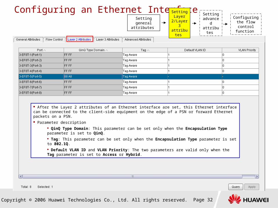
After the Layer 2 attributes of an Ethernet interface are set, this Ethernet interface can be connected to the client-side equipment on the edge of a PSN or forward Ethernet packets on a PSN. Parameter description
QinQ Type Domain: This parameter can be set only when the Encapsulation Type parameter is set to QinQ. Tag: This parameter can be set only when the Encapsulation Type parameter is set to 802.1Q. Default VLAN ID and VLAN Priority: The two parameters are valid only when the Tag parameter is set to Access or Hybrid.

Copyright © 2006 Huawei Technologies Co., Ltd. All rights reserved. Page 33
Configuring an Ethernet Interface
Setting general attributes
Setting Layer
2/Layer 3 attributes
Configuring the flow control
function
Setting advanced attributes
If an Ethernet interface is used to carry the tunnel, the Layer 3 attributes of the Ethernet interface need to be set.
Parameter description
Enable Tunnel: After a tunnel is enabled, the port can identify and process the MPLS label, and thus can support the dynamic signaling and routing.
Max Reserved Bandwidth (kbit/s): This parameter specifies the bandwidth used by a tunnel. The maximum reserved bandwidth should not be higher than the physical bandwidth at the port.
TE Measurement: This parameter allows manual intervention in routing. When the value of this parameter is smaller, the priority of the link is higher. In this manner, traffic congestion on the shortest path, which occurs in conventional routing, can be prevented.
Admin Group: This parameter specifies the link attribute. After the affinity attribute of a dynamic tunnel is set, it compares its affinity attribute with the admin group attribute of links in the case of link selection. In this manner, the dynamic tunnel can determine which links should be selected or avoided.
IP Address: Ensure that the IP address of the interface is not in the same subnet as the IP addresses of other interfaces that are already configured with services.
Board for Unnumbered IP and Port for Unnumbered IP: The two parameters cannot be set.
Copyright © 2006 Huawei Technologies Co., Ltd. All rights reserved. Page 34
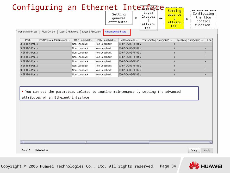
Configuring an Ethernet Interface
Setting general attributes
Setting Layer
2/Layer 3 attributes
Configuring the flow control
function
Setting advanced attributes
You can set the parameters related to routine maintenance by setting the advanced attributes of an Ethernet interface.
Copyright © 2006 Huawei Technologies Co., Ltd. All rights reserved. Page 35
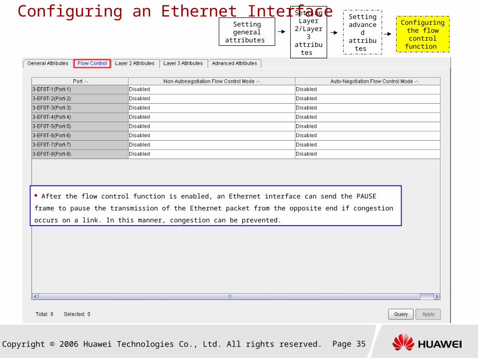
Configuring an Ethernet Interface
Setting general attributes
Setting Layer
2/Layer 3 attributes
Configuring the flow control
function
Setting advanced attributes
After the flow control function is enabled, an Ethernet interface can send the PAUSE frame to pause the transmission of
the Ethernet packet from the opposite end if congestion occurs on a link. In this manner, congestion can be prevented.

Copyright © 2006 Huawei Technologies Co., Ltd. All rights reserved. Page 36
Tasks Involved in Configuration of the Ethernet Service
Creating an NE
Setting the LSR ID
Configuring an interface
Configuring the control plane
Creating a tunnel
Configuring the E-Line service
Configuring the E-Aggr service
Copyright © 2006 Huawei Technologies Co., Ltd. All rights reserved. Page 37
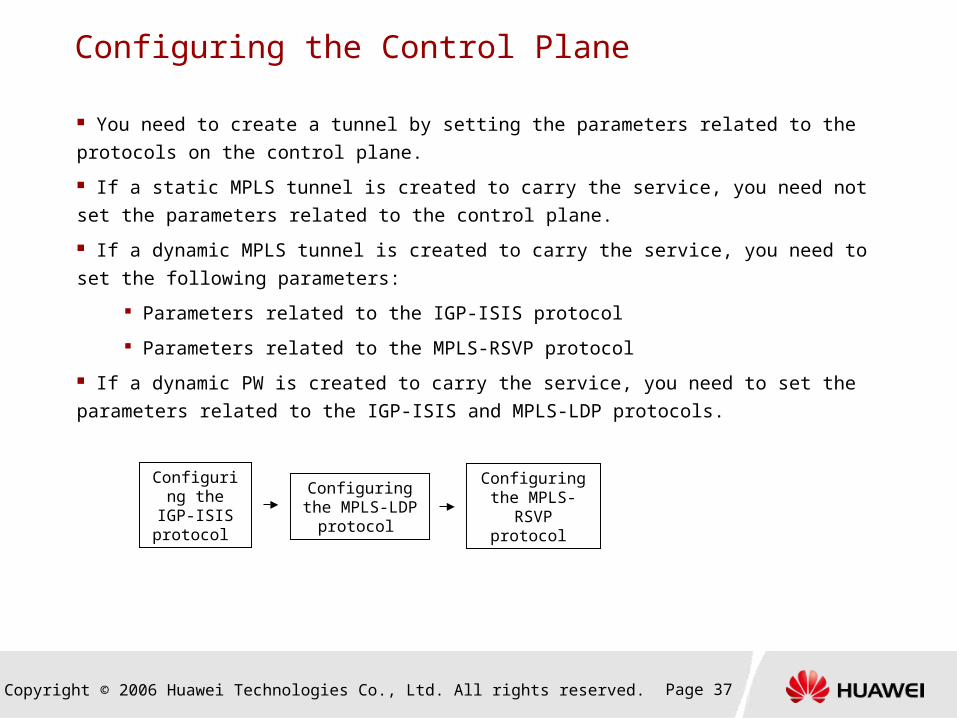
Configuring the Control Plane
You need to create a tunnel by setting the parameters related to the protocols on the control
plane.
If a static MPLS tunnel is created to carry the service, you need not set the parameters related
to the control plane.
If a dynamic MPLS tunnel is created to carry the service, you need to set the following
parameters:
Parameters related to the IGP-ISIS protocol
Parameters related to the MPLS-RSVP protocol
If a dynamic PW is created to carry the service, you need to set the parameters related to the
IGP-ISIS and MPLS-LDP protocols.
Configuring the IGP-ISIS
protocol
Configuring the MPLS-LDP
protocol
Configuring the MPLS-RSVP
protocol

Copyright © 2006 Huawei Technologies Co., Ltd. All rights reserved. Page 38
Configuring the Control Plane
Configuring the IGP-ISIS protocol
Configuring the MPLS-LDP protocol
Configuring the MPLS-RSVP
protocol
Copyright © 2006 Huawei Technologies Co., Ltd. All rights reserved. Page 39
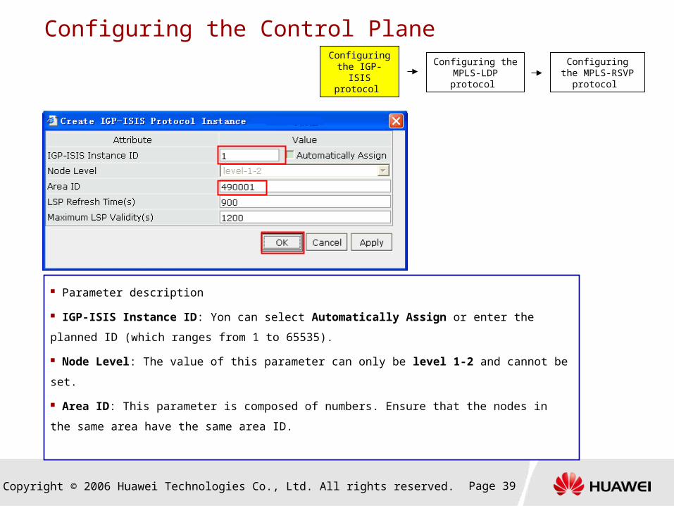
Configuring the Control Plane
Parameter description
IGP-ISIS Instance ID: Yon can select Automatically Assign or enter the planned ID (which ranges
from 1 to 65535).
Node Level: The value of this parameter can only be level 1-2 and cannot be set.
Area ID: This parameter is composed of numbers. Ensure that the nodes in the same area have the
same area ID.
Configuring the IGP-ISIS protocol
Configuring the MPLS-LDP protocol
Configuring the MPLS-RSVP
protocol
Copyright © 2006 Huawei Technologies Co., Ltd. All rights reserved. Page 40
Configuring the Control Plane
Configuring the IGP-ISIS protocol
Configuring the MPLS-LDP protocol
Configuring the MPLS-RSVP
protocol
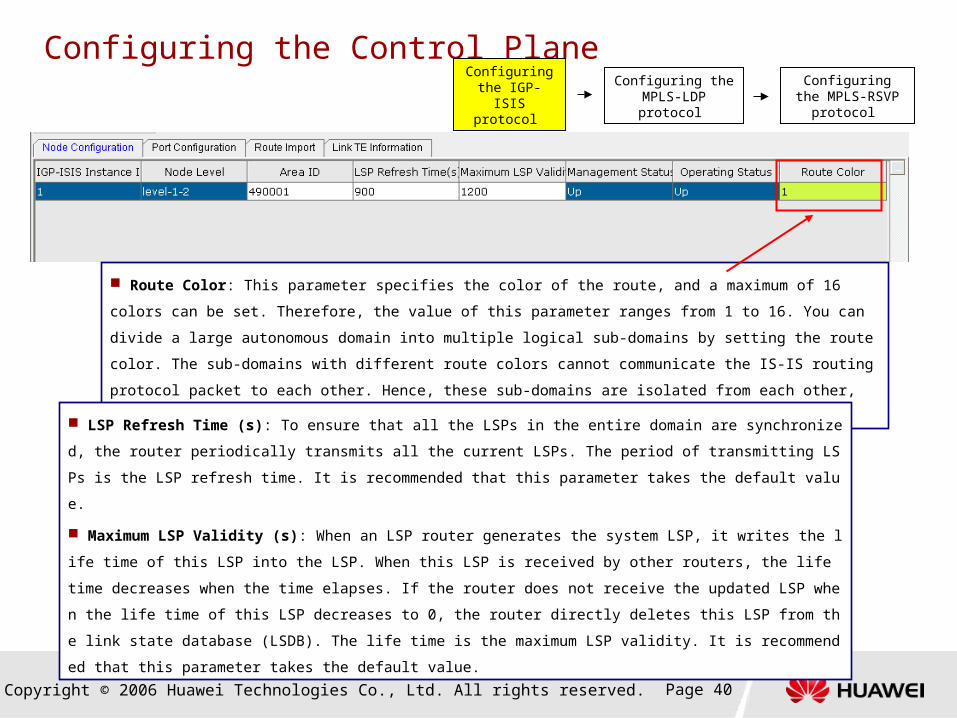
Route Color: This parameter specifies the color of the route, and a maximum of 16 colors can be set. Therefore,
the value of this parameter ranges from 1 to 16. You can divide a large autonomous domain into multiple logical sub-
domains by setting the route color. The sub-domains with different route colors cannot communicate the IS-IS routing
protocol packet to each other. Hence, these sub-domains are isolated from each other, which facilitates link
management and maintenance.
LSP Refresh Time (s): To ensure that all the LSPs in the entire domain are synchronized, the router periodically tran
smits all the current LSPs. The period of transmitting LSPs is the LSP refresh time. It is recommended that this parame
ter takes the default value.
Maximum LSP Validity (s): When an LSP router generates the system LSP, it writes the life time of this LSP into th
e LSP. When this LSP is received by other routers, the life time decreases when the time elapses. If the router does no
t receive the updated LSP when the life time of this LSP decreases to 0, the router directly deletes this LSP from the lin
k state database (LSDB). The life time is the maximum LSP validity. It is recommended that this parameter takes the d
efault value.
Copyright © 2006 Huawei Technologies Co., Ltd. All rights reserved. Page 41
Configuring the Control Plane
Configuring the IGP-ISIS protocol
Configuring the MPLS-LDP protocol
Configuring the MPLS-RSVP
protocol
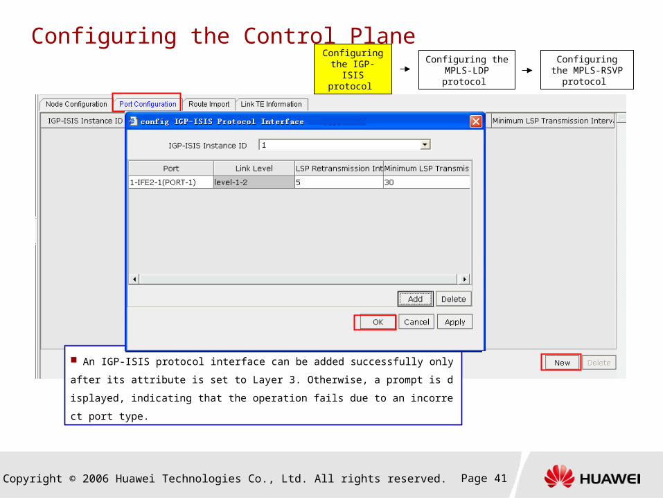
An IGP-ISIS protocol interface can be added successfully only after its attribute is s
et to Layer 3. Otherwise, a prompt is displayed, indicating that the operation fails due
to an incorrect port type.

Copyright © 2006 Huawei Technologies Co., Ltd. All rights reserved. Page 42
Configuring the Control Plane
Unless otherwise specified, the Link Overhead, Authentication Mode, Hello Send Interval, and Hello
Loss Count parameters take the default values. If there are special requirements, set these parameters
according to the network design.
Configuring the IGP-ISIS protocol
Configuring the MPLS-LDP protocol
Configuring the MPLS-RSVP
protocol

Copyright © 2006 Huawei Technologies Co., Ltd. All rights reserved. Page 43
Configuring the Control Plane
Configuring the IGP-ISIS protocol
Configuring the MPLS-LDP protocol
Configuring the MPLS-RSVP
protocol
This parameter specifies the
cost of the imported route,
namely, the routing metric.
Copyright © 2006 Huawei Technologies Co., Ltd. All rights reserved. Page 44
Configuring the Control Plane
If the dynamic PW needs to be created, the MPLS-LDP protocol must be configured. The MPLS-LDP protocol is
used to create the dynamic PW and to dynamically allocate the PW label. By running the MPLS-LDP protocol, an
NE only knows its neighboring NEs. In the case of a single service, the MPLS-LDP peer entity specified in the
MPLS-LDP protocol should be configured so that the NEs at both ends can know each other. On the T2000, you
can create the MPLS-LDP peer entity and configure the MPLS-LDP protocol.
In the case of the local session and remote session, it is required to create bidirectional LDP peer entities
between the source equipment and sink equipment is required. That is, peer entities should be created from the
source to the sink and from the sink to the source.
Configuring the IGP-ISIS protocol
Configuring the MPLS-LDP protocol
Configuring the MPLS-RSVP
protocol

Copyright © 2006 Huawei Technologies Co., Ltd. All rights reserved. Page 45
Configuring the Control Plane
Set the LSR ID of the
opposite end.
Configuring the IGP-ISIS protocol
Configuring the MPLS-LDP protocol
Configuring the MPLS-RSVP
protocol
Copyright © 2006 Huawei Technologies Co., Ltd. All rights reserved. Page 46
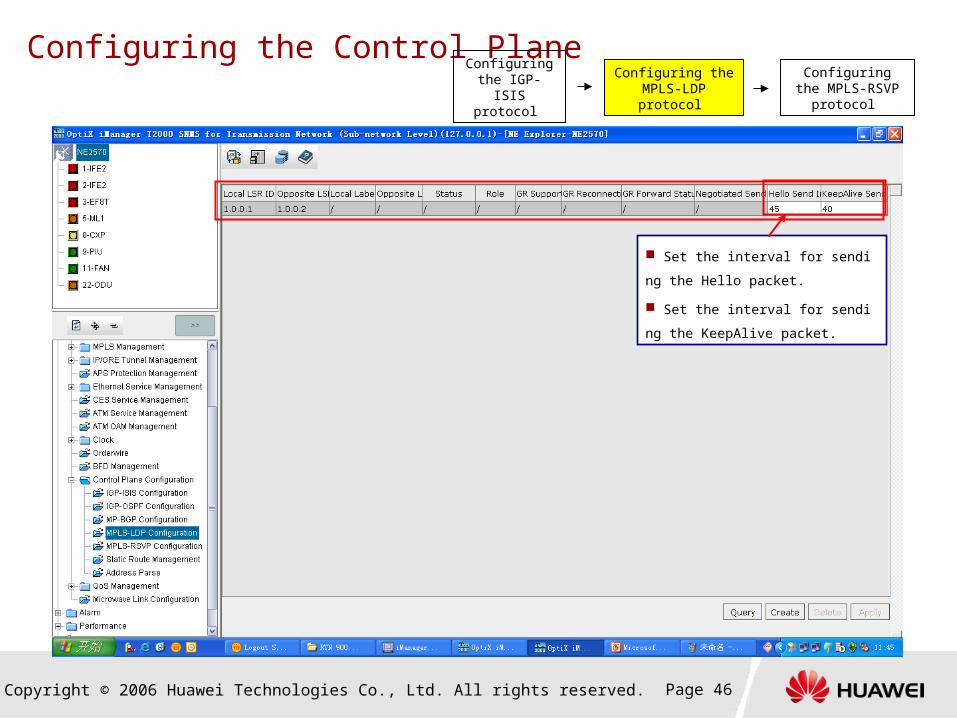
Configuring the Control Plane
Set the interval for sending the Hello
packet.
Set the interval for sending the Keep
Alive packet.
Configuring the IGP-ISIS protocol
Configuring the MPLS-LDP protocol
Configuring the MPLS-RSVP
protocol

Copyright © 2006 Huawei Technologies Co., Ltd. All rights reserved. Page 47
Configuring the Control Plane
The MPLS-RSVP protocol is used to create the dynamic MPLS tunnel and to allocate the label of the
dynamic tunnel. On the T2000, you can set and query the parameters related to the MPLS-RSVP
protocol. The MPLS-RSVP protocol need not be specially configured, and you can set each parameter
according to requirements.
Configuring the IGP-ISIS protocol
Configuring the MPLS-LDP protocol
Configuring the MPLS-RSVP
protocol

Copyright © 2006 Huawei Technologies Co., Ltd. All rights reserved. Page 48
Configuring the Control Plane
Static route is obtained according to the preset routing options for the network.
On the T2000, you can create and query the static route.

Copyright © 2006 Huawei Technologies Co., Ltd. All rights reserved. Page 49
Configuring the Control Plane
Select the boards and ports that have Layer 3 attributes.
The IP address of the port and the IP address of the next hop must be in the same network segment when the static route is configured.
When the last digit of the destination node IP address is not 0, the destination node subnet mask is 255.255.255.255. For example, if the
destination node IP address is 193.168.3.2, the destination node subnet mask is 255.255.255.255.
When the last digit of the destination node IP address is 0, the destination node subnet mask is 255.255.255.0 or 255.255.255.255. For
example, if the destination node IP address is 193.168.3.0, the destination node subnet mask is 255.255.255.255 or 255.255.255.0.
Copyright © 2006 Huawei Technologies Co., Ltd. All rights reserved. Page 50
Tasks Involved in Configuration of the Ethernet Service
Creating an NE
Setting the LSR ID
Configuring an interface
Configuring the control plane
Creating a tunnel
Configuring the E-Line service
Configuring the E-Aggr service

Copyright © 2006 Huawei Technologies Co., Ltd. All rights reserved. Page 51
Creating a Tunnel
On a PSN, an MPLS tunnel carries PWs that encapsulate various services, and thus realizes transparent transmission of data packets betw
een NEs. Multiple PWs can be transmitted in one MPLS tunnel. Hence, you need to configure the MPLS tunnel before configuring a service.
On the T2000, you can create a unicast tunnel by using either of the following methods:
Configuration on a per-NE basis: To create a unicast MPLS tunnel, you need to set the related parameters, including the ingress por
t and IP address of the next hop, for each NE that an MPLS tunnel traverses.
Configuration by using the trail function: This method includes static configuration and dynamic configuration.
Static configuration: To create a unicast MPLS tunnel, you need to specify the source NE and sink NE of this MPLS tunnel,
and the intermediate NEs that this MPLS tunnel traverses.
Dynamic configuration: To create a unicast MPLS tunnel, you need to specify only the source NE and sink NE of this MPLS
tunnel and then the equipment creates a unicast MPLS tunnel through signaling transmission.
The following description considers the configuration on a per-NE basis as an example to describe how to create an MPLS tunnel. For detail
s about the method for creating an MPLS tunnel by using the trail function, see the related description in the Configuration Guide contained in
the package of documents.

Copyright © 2006 Huawei Technologies Co., Ltd. All rights reserved. Page 52
Creating a Tunnel
Copyright © 2006 Huawei Technologies Co., Ltd. All rights reserved. Page 53
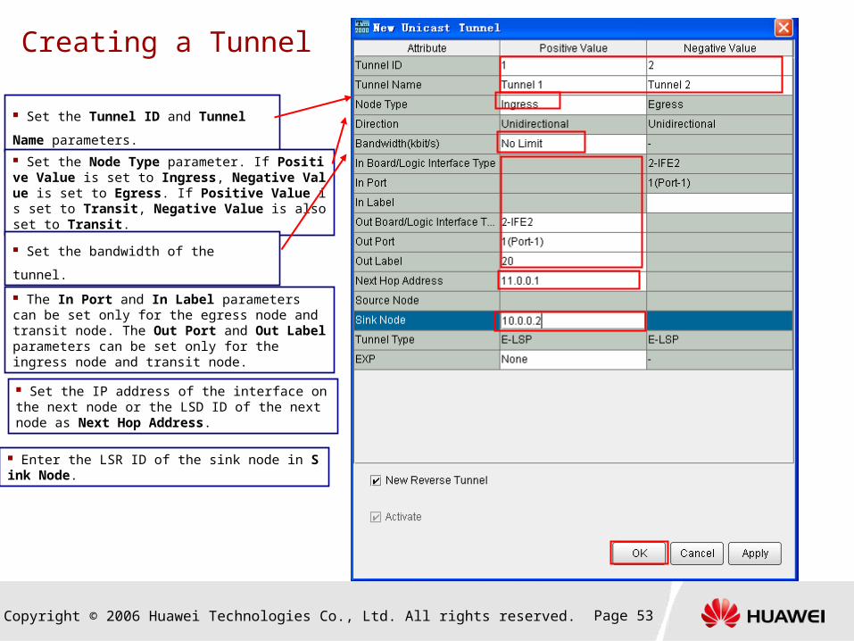
Creating a Tunnel
Set the Tunnel ID and Tunnel Name
parameters.
Set the Node Type parameter. If Positive Value is set to Ingress, Negative Value is set to Egress. If Positive Value is set to Transit, Negative Value is also set to Transit.
Set the bandwidth of the tunnel.
The In Port and In Label parameters can be set only for the egress node and transit node. The Out Port and Out Label parameters can be set only for the ingress node and transit node.
Set the IP address of the interface on the next node or the LSD ID of the next node as Next Hop Address.
Enter the LSR ID of the sink node in Sink Node.
Copyright © 2006 Huawei Technologies Co., Ltd. All rights reserved. Page 54
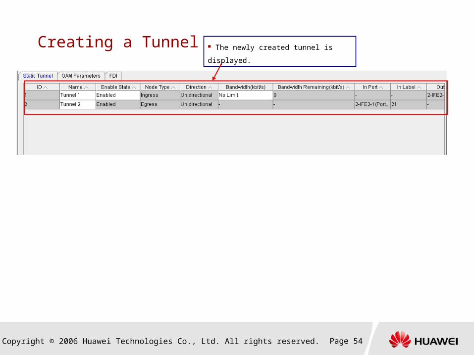
Creating a Tunnel The newly created tunnel is displayed.
Copyright © 2006 Huawei Technologies Co., Ltd. All rights reserved. Page 55
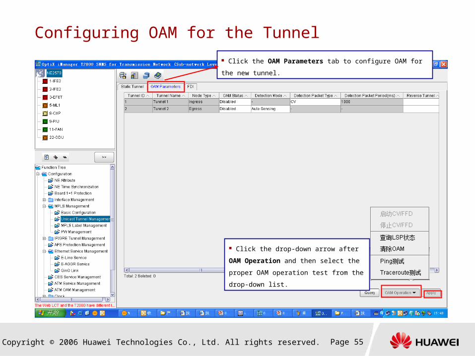
Configuring OAM for the Tunnel
Click the OAM Parameters tab to configure OAM for the new tunnel.
Click the drop-down arrow after OAM
Operation and then select the proper OAM
operation test from the drop-down list.

Copyright © 2006 Huawei Technologies Co., Ltd. All rights reserved. Page 56
Creating an MPLS Tunnel Protection Group

Copyright © 2006 Huawei Technologies Co., Ltd. All rights reserved. Page 57
Creating an MPLS Tunnel Protection Group
Set the parameters of a tunnel protection group.
Protection Type: The value can be 1+1 or 1:1.
Switching Mode: The value can be Single-Ended or Dual-
Ended. When the Protection Type parameter is set to 1:1, the
Switching Mode parameter can only be Dual-Ended.
Revertive Mode: The value can be Non-Revertive or
Revertive.
Hold-off Time (100ms): The value is in 100 milliseconds and
is an integer ranging from 0 to 100 (namely, 0 to 10 seconds).
Copyright © 2006 Huawei Technologies Co., Ltd. All rights reserved. Page 58
Tasks Involved in Configuration of the Ethernet Service
Creating an NE
Setting the LSR ID
Configuring an interface
Configuring the control plane
Creating a tunnel
Configuring the E-Line service
Configuring the E-Aggr service
Copyright © 2006 Huawei Technologies Co., Ltd. All rights reserved. Page 59
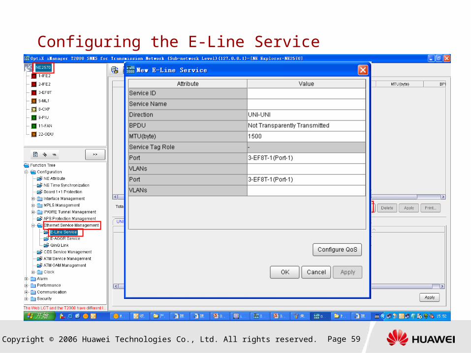
Configuring the E-Line Service
Copyright © 2006 Huawei Technologies Co., Ltd. All rights reserved. Page 60
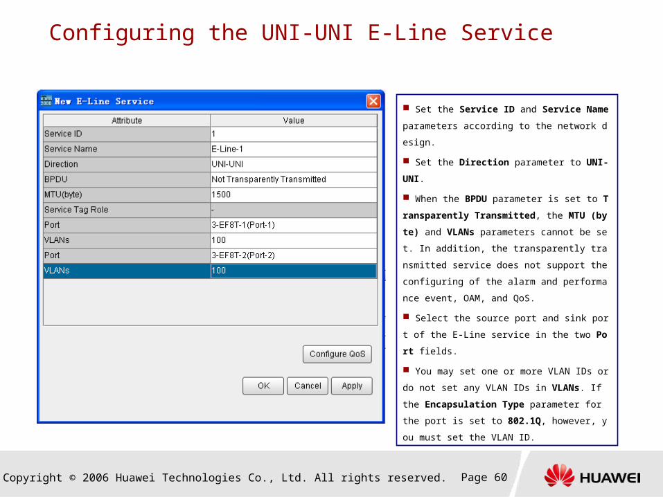
Configuring the UNI-UNI E-Line Service
Set the Service ID and Service Name paramete
rs according to the network design.
Set the Direction parameter to UNI-UNI.
When the BPDU parameter is set to Transparen
tly Transmitted, the MTU (byte) and VLANs para
meters cannot be set. In addition, the transparently
transmitted service does not support the configurin
g of the alarm and performance event, OAM, and Q
oS.
Select the source port and sink port of the E-Line
service in the two Port fields.
You may set one or more VLAN IDs or do not set
any VLAN IDs in VLANs. If the Encapsulation Ty
pe parameter for the port is set to 802.1Q, however,
you must set the VLAN ID.

Copyright © 2006 Huawei Technologies Co., Ltd. All rights reserved. Page 61
Configuring the UNI-NNI E-Line Service Carried by a Port
Set the Service ID and Service Name parameters ac
cording to the network design.
Set the Direction parameter to UNI-NNI.
When the BPDU parameter is set to Transparently T
ransmitted, the MTU (byte) and VLANs parameters ca
nnot be set. In addition, the transparently transmitted se
rvice does not support the configuring of the alarm and
performance event, OAM, and QoS.
The UNI should be the Ethernet interface that access
es the Ethernet service.
You may set one or more VLAN IDs or do not set any
VLAN IDs in the VLANs field.
Set the Bearer Type parameter to Port.
The NNI should be the IF interface that has Layer 2 a
ttributes and carries the Ethernet service.
Copyright © 2006 Huawei Technologies Co., Ltd. All rights reserved. Page 62
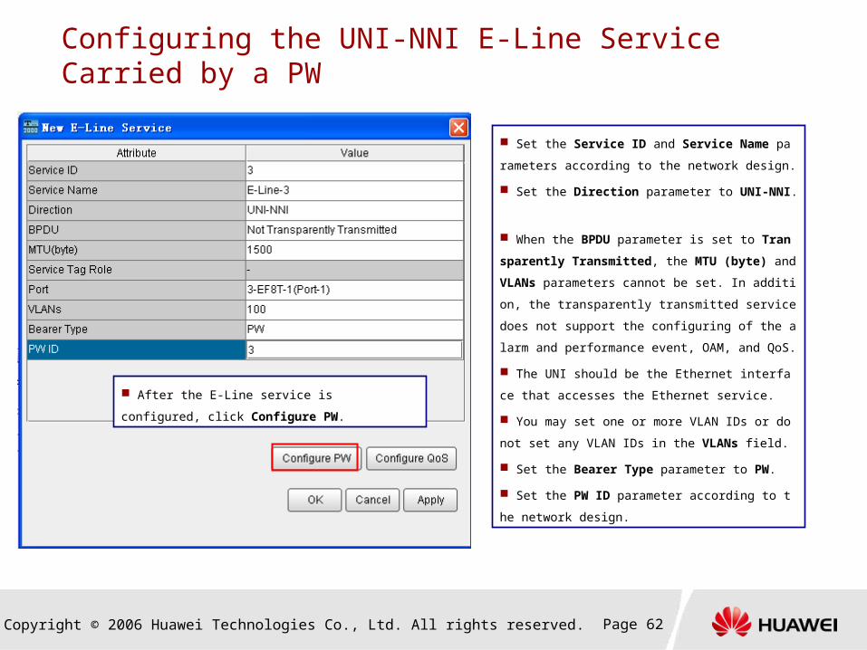
Configuring the UNI-NNI E-Line Service Carried by a PW
Set the Service ID and Service Name parameters ac
cording to the network design.
Set the Direction parameter to UNI-NNI.
When the BPDU parameter is set to Transparently T
ransmitted, the MTU (byte) and VLANs parameters ca
nnot be set. In addition, the transparently transmitted se
rvice does not support the configuring of the alarm and
performance event, OAM, and QoS.
The UNI should be the Ethernet interface that access
es the Ethernet service.
You may set one or more VLAN IDs or do not set any
VLAN IDs in the VLANs field.
Set the Bearer Type parameter to PW.
Set the PW ID parameter according to the network de
sign.
After the E-Line service is configured, click
Configure PW.

Copyright © 2006 Huawei Technologies Co., Ltd. All rights reserved. Page 63
Configuring the UNI-NNI E-Line Service Carried by a PW
PW ID: The value should be the same as the PW ID of the
E-Line service.
PW Signaling Type: This parameter can be set to Static or
Dynamic according to the network design. If this parameter is
set to Dynamic, the PW Encapsulation Type, PW Ingress
Label/Source Port, and PW Egress Label/Sink Port
parameters need not be set.
PW Type: The value can be Ethernet or Ethernet Tagged
Mode. If this parameter is set to Ethernet Tagged Mode, the
service that uses this PW is tagged.
Direction: This parameter takes the default value
Bidirectional and cannot be modified.
PW Encapsulation Type: Set this parameter to MPLS.
PW Ingress Label/Source Port, PW Egress Label/Sink
Port: Set the parameters according to the network design.
Tunnel Type: Set this parameter to MPLS. If the PW
Encapsulation Type parameter is set to UDP, the Tunnel
Type parameter can only be set to IP.
PW ID: Set this parameter according to the network design.
Click the
following
button.
Select a tunnel that is already created.
Copyright © 2006 Huawei Technologies Co., Ltd. All rights reserved. Page 64
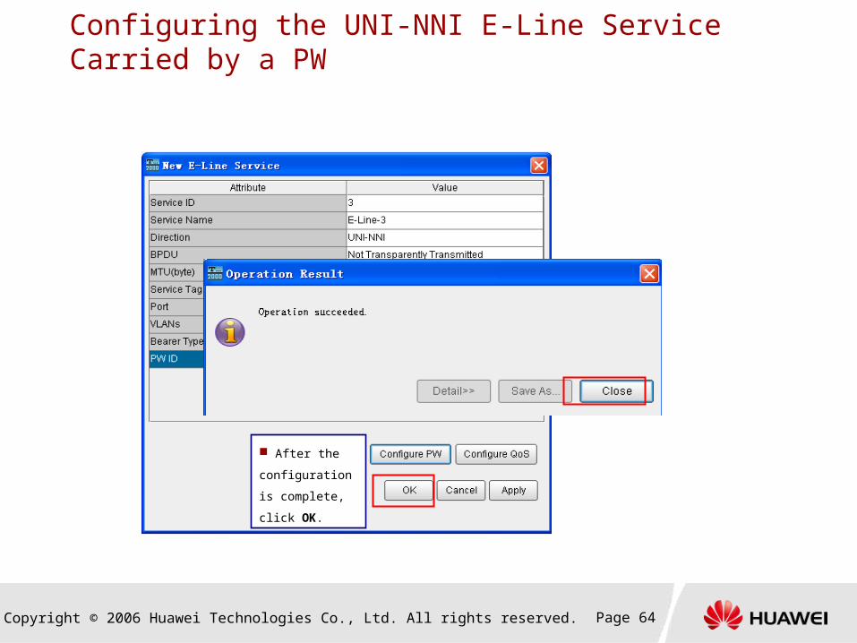
Configuring the UNI-NNI E-Line Service Carried by a PW
After the
configuration is
complete, click
OK.
Copyright © 2006 Huawei Technologies Co., Ltd. All rights reserved. Page 65
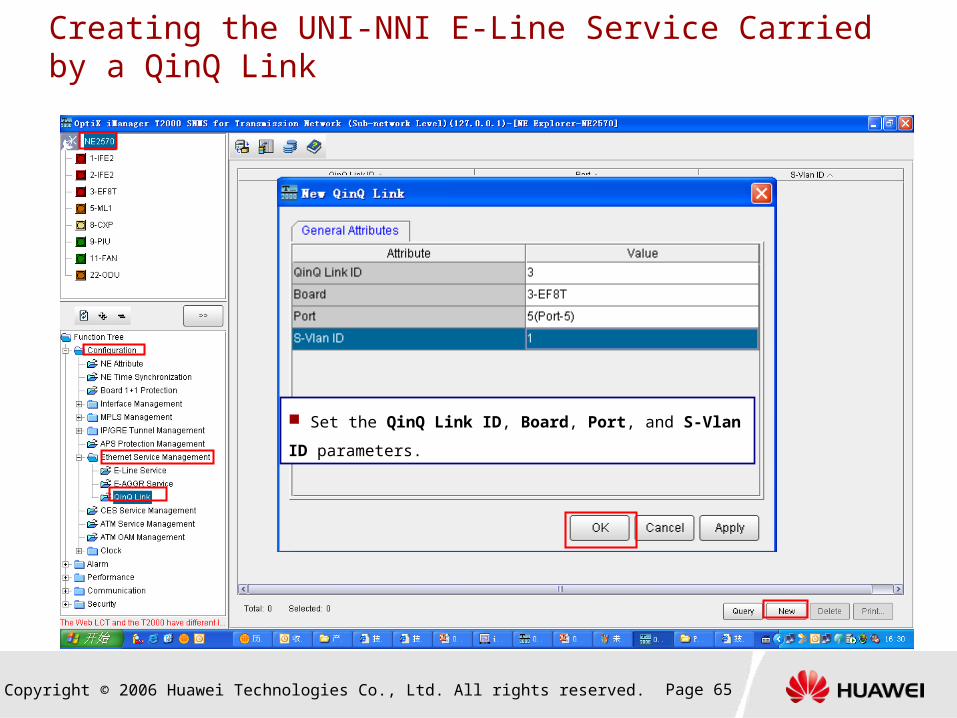
Creating the UNI-NNI E-Line Service Carried by a QinQ Link
Set the QinQ Link ID, Board, Port, and S-Vlan ID parameter
s.

Copyright © 2006 Huawei Technologies Co., Ltd. All rights reserved. Page 66
Creating the UNI-NNI E-Line Service Carried by a QinQ Link
Copyright © 2006 Huawei Technologies Co., Ltd. All rights reserved. Page 67
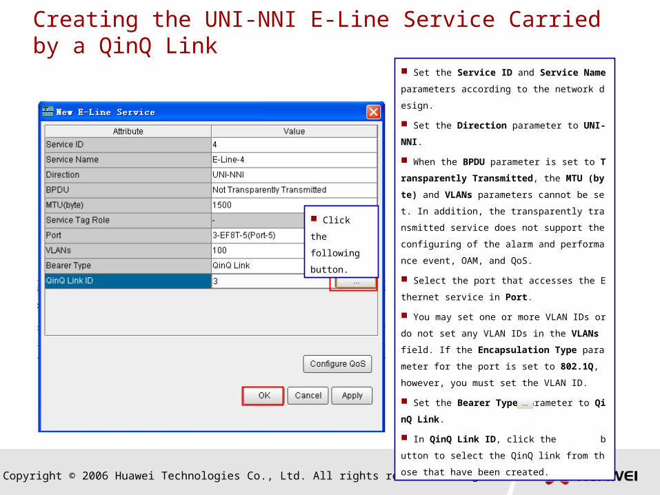
Creating the UNI-NNI E-Line Service Carried by a QinQ Link
Set the Service ID and Service Name paramete
rs according to the network design.
Set the Direction parameter to UNI-NNI.
When the BPDU parameter is set to Transparen
tly Transmitted, the MTU (byte) and VLANs para
meters cannot be set. In addition, the transparently
transmitted service does not support the configurin
g of the alarm and performance event, OAM, and Q
oS.
Select the port that accesses the Ethernet servic
e in Port.
You may set one or more VLAN IDs or do not set
any VLAN IDs in the VLANs field. If the Encapsula
tion Type parameter for the port is set to 802.1Q, h
owever, you must set the VLAN ID.
Set the Bearer Type parameter to QinQ Link.
In QinQ Link ID, click the button to select th
e QinQ link from those that have been created.
Click the
following
button.
Copyright © 2006 Huawei Technologies Co., Ltd. All rights reserved. Page 68
Tasks Involved in Configuration of the Ethernet Service
Creating an NE
Setting the LSR ID
Configuring an interface
Configuring the control plane
Creating a tunnel
Configuring the E-Line service
Configuring the E-Aggr service
Copyright © 2006 Huawei Technologies Co., Ltd. All rights reserved. Page 69
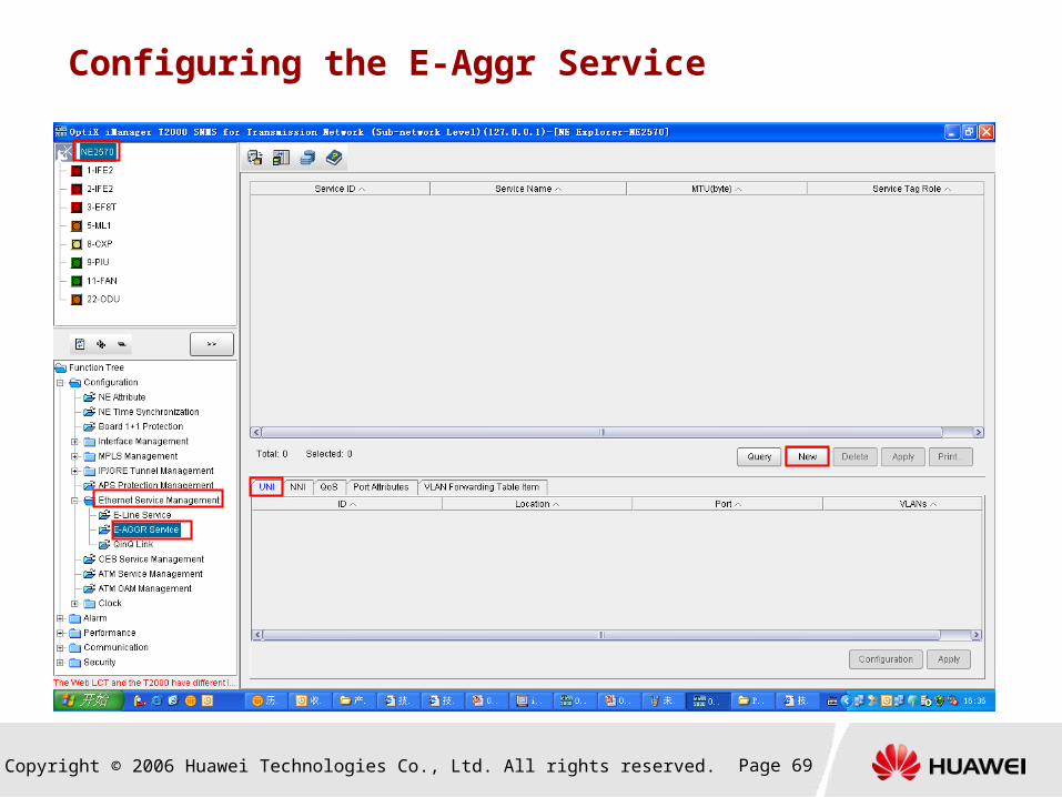
Configuring the E-Aggr Service

Copyright © 2006 Huawei Technologies Co., Ltd. All rights reserved. Page 70
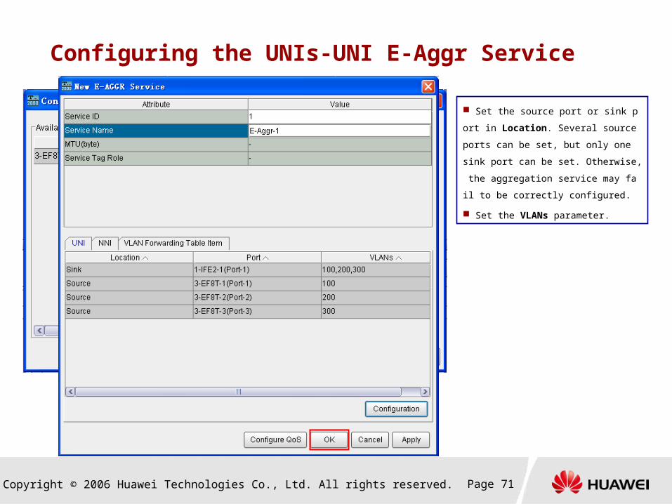
Configuring the UNIs-UNI E-Aggr Service
Set the Service ID and Service Name
parameters according to the network
design.
Copyright © 2006 Huawei Technologies Co., Ltd. All rights reserved. Page 71
Configuring the UNIs-UNI E-Aggr Service
Set the source port or sink port in Locati
on. Several source ports can be set, but on
ly one sink port can be set. Otherwise, the
aggregation service may fail to be correctly
configured.
Set the VLANs parameter.

Copyright © 2006 Huawei Technologies Co., Ltd. All rights reserved. Page 72
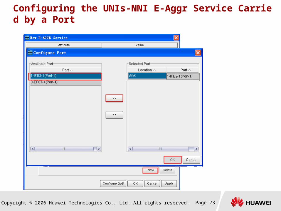
Configuring the UNIs-NNI E-Aggr Service
Set the Service ID and Service Name
parameters according to the network
design.
Select the UNI and set the Locatio
n and VLANs parameters for the port.
In the case of the aggregation servic
e from UNIs to one NNI, you can sele
ct several UNIs and set their Locatio
n parameter to Source.
Copyright © 2006 Huawei Technologies Co., Ltd. All rights reserved. Page 73
Configuring the UNIs-NNI E-Aggr Service Carried by a Port
Copyright © 2006 Huawei Technologies Co., Ltd. All rights reserved. Page 74
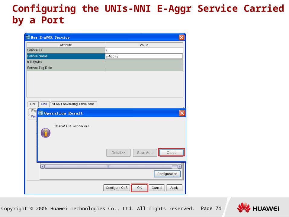
Configuring the UNIs-NNI E-Aggr Service Carried by a Port
Copyright © 2006 Huawei Technologies Co., Ltd. All rights reserved. Page 75
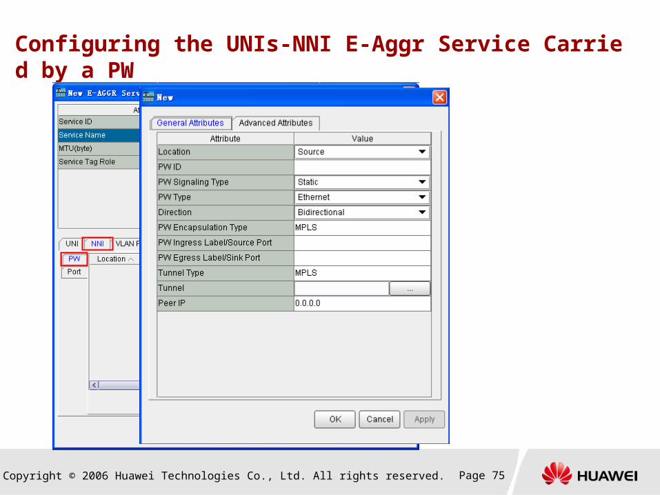
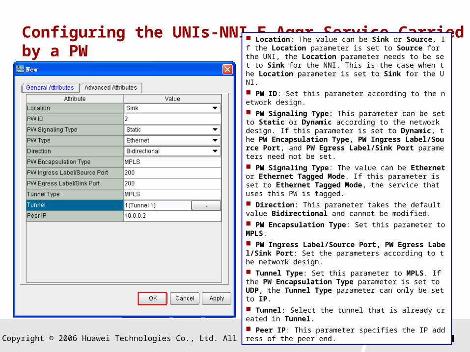
Configuring the UNIs-NNI E-Aggr Service Carried by a PW
Copyright © 2006 Huawei Technologies Co., Ltd. All rights reserved. Page 76
Configuring the UNIs-NNI E-Aggr Service Carried by a PW
Location: The value can be Sink or Source. If the Location parameter is set to Source for the UNI, the Location parameter needs to be set to Sink for the NNI. This is the case when the Location parameter is set to Sink for the UNI.
PW ID: Set this parameter according to the network design.
PW Signaling Type: This parameter can be set to Static or Dynamic according to the network design. If this parameter is set to Dynamic, the PW Encapsulation Type, PW Ingress Label/Source Port, and PW Egress Label/Sink Port parameters need not be set.
PW Signaling Type: The value can be Ethernet or Ethernet Tagged Mode. If this parameter is set to Ethernet Tagged Mode, the service that uses this PW is tagged.
Direction: This parameter takes the default value Bidirectional and cannot be modified.
PW Encapsulation Type: Set this parameter to MPLS.
PW Ingress Label/Source Port, PW Egress Label/Sink Port: Set the parameters according to the network design.
Tunnel Type: Set this parameter to MPLS. If the PW Encapsulation Type parameter is set to UDP, the Tunnel Type parameter can only be set to IP.
Tunnel: Select the tunnel that is already created in Tunnel.
Peer IP: This parameter specifies the IP address of the peer end.

Copyright © 2006 Huawei Technologies Co., Ltd. All rights reserved. Page 77
Configuring the UNIs-NNI E-Aggr Service Carried by a PW

Copyright © 2006 Huawei Technologies Co., Ltd. All rights reserved. Page 78
Contents
1. Types of Services on the OptiX RTN 900
V100R001
2. Configuring the Ethernet Service
3. Configuring the CES Service
Configuration Process
Configuration Tasks
4. Configuring the ATM/IMA Service

Copyright © 2006 Huawei Technologies Co., Ltd. All rights reserved. Page 79
Configuring the CES Service
Start
Create a network
Configure an interface
Configure the UNI-UNI CES service Configure the control
plane
Configure the tunnel
Configure the UNI-NNI CES service
End
UNI-UNI CES service UNI-NNI CES service
You need to create NEs, configure the
NE data, create fibers, and configure
clocks.
You need to configure the UNI and NNI. The UNI
should be a PDH interface that has Layer 1
attributes. The NNI should be a radio interface that
has Layer 3 attributes.
You need to create a tunnel by
setting the parameters related to
the protocols on the control
plane.
If a dynamic MPLS tunnel is
created to carry the CES service,
you need to set the parameters
related to the IGP-ISIS and
MPLS-RSVP protocols.
If a dynamic PW is created to
carry the service, you need to set
the parameters related to the
IGP-ISIS and MPLS-LDP
protocols.
You need to set the service I
D and service name, and spec
ify the source and sink.
The tunnel carries t
he service.
Copyright © 2006 Huawei Technologies Co., Ltd. All rights reserved. Page 80
Tasks Involved in Configuration of the CES Service
Creating an NE
Setting the LSR ID
Configuring an interface
Configuring a radio interface
Configuring a PDH interface
Configuring the control plane
Creating a tunnel
Configuring the CES service
UNI-UNI
UNI-NNI
Copyright © 2006 Huawei Technologies Co., Ltd. All rights reserved. Page 81
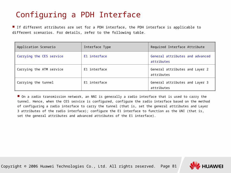
Configuring a PDH Interface If different attributes are set for a PDH interface, the PDH interface is applicable to different scenarios. For details, refer to
the following table.
Application Scenario Interface Type Required Interface Attribute
Carrying the CES service E1 interface General attributes and advanced attributes
Carrying the ATM service E1 interface General attributes and Layer 2 attributes
Carrying the tunnel E1 interface General attributes and Layer 3 attributes
On a radio transmission network, an NNI is generally a radio interface that is used to carry the tunnel. Hence, when the CES service is
configured, configure the radio interface based on the method of configuring a radio interface to carry the tunnel (that is, set the general
attributes and Layer 3 attributes of the radio interface); configure the E1 interface to function as the UNI (that is, set the general attributes
and advanced attributes of the E1 interface).

Copyright © 2006 Huawei Technologies Co., Ltd. All rights reserved. Page 82
Configuring a PDH Interface
Double-click Port Mode of a certain port, and Layer 1,
Layer 2, and Layer 3 are displayed for your selection. If
the TDM service is accessed on the UNI side, select
Layer 1.
When the Port Mode parameter is set to Layer 1, the Encapsulation Type parameter cannot be set. In this case, the TDM service can be accessed. When the Port Mode parameter is set to Layer 2, the Encapsulation Type parameter can only be set to ATM. In this case, the ATM service can be accessed. When a PDH interface is used for the inband DCN, the Port Mode parameter for the PDH interface cannot be set to Layer 2 or Layer 1. When the Port Mode parameter is set to Layer 3, the Encapsulation Type parameter can be set to Null or PPP. If the Encapsulation Type parameter is set to Null, the PPP protocol is not enabled at the interface and thus the equipment carries less load. If the Encapsulation Type parameter is set to PPP, the interface can carry the MPLS.
Copyright © 2006 Huawei Technologies Co., Ltd. All rights reserved. Page 83
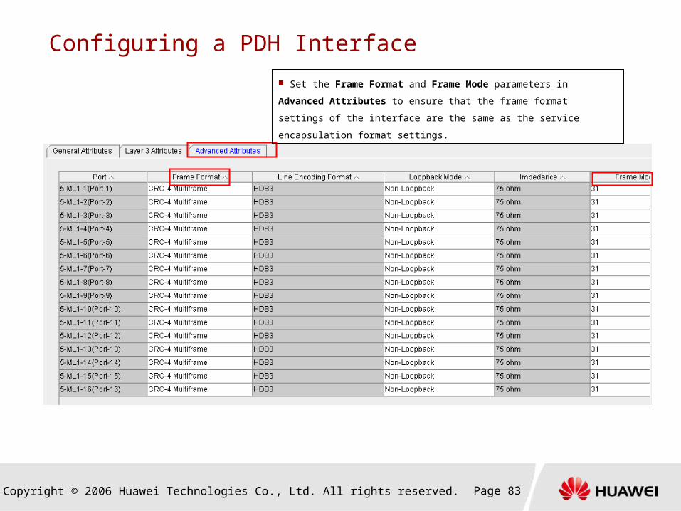
Configuring a PDH Interface
Set the Frame Format and Frame Mode parameters in Advanced Attributes
to ensure that the frame format settings of the interface are the same as the
service encapsulation format settings.
Copyright © 2006 Huawei Technologies Co., Ltd. All rights reserved. Page 84
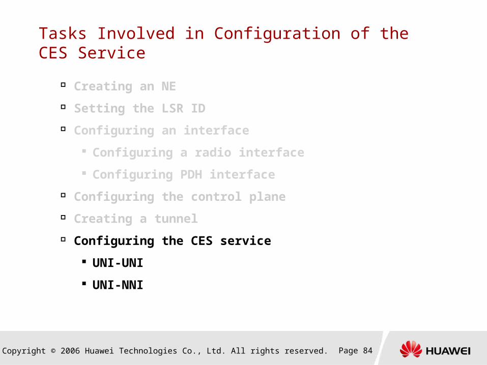
Tasks Involved in Configuration of the CES Service
Creating an NE
Setting the LSR ID
Configuring an interface
Configuring a radio interface
Configuring PDH interface
Configuring the control plane
Creating a tunnel
Configuring the CES service
UNI-UNI
UNI-NNI

Copyright © 2006 Huawei Technologies Co., Ltd. All rights reserved. Page 85
Configuring the CES Service
Copyright © 2006 Huawei Technologies Co., Ltd. All rights reserved. Page 86
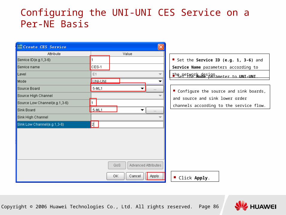
Configuring the UNI-UNI CES Service on a Per-NE Basis
Set the Service ID (e.g. 1, 3-6) and Service Name
parameters according to the network design.
Set the Mode parameter to UNI-UNI.
Configure the source and sink boards, and source
and sink lower order channels according to the
service flow.
Click Apply.
Copyright © 2006 Huawei Technologies Co., Ltd. All rights reserved. Page 87
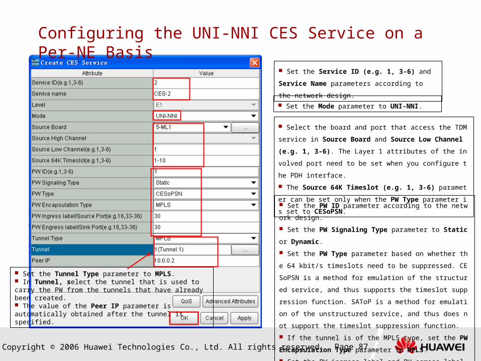
Configuring the UNI-NNI CES Service on a Per-NE Basis
Set the Service ID (e.g. 1, 3-6) and Service Name
parameters according to the network design.
Set the Mode parameter to UNI-NNI.
Select the board and port that access the TDM service in Sour
ce Board and Source Low Channel (e.g. 1, 3-6). The Layer 1 a
ttributes of the involved port need to be set when you configure t
he PDH interface.
The Source 64K Timeslot (e.g. 1, 3-6) parameter can be set
only when the PW Type parameter is set to CESoPSN.
Set the PW ID parameter according to the network design.
Set the PW Signaling Type parameter to Static or Dynamic.
Set the PW Type parameter based on whether the 64 kbit/s ti
meslots need to be suppressed. CESoPSN is a method for emul
ation of the structured service, and thus supports the timeslot su
ppression function. SAToP is a method for emulation of the unstr
uctured service, and thus does not support the timeslot suppress
ion function.
If the tunnel is of the MPLS type, set the PW Encapsulation T
ype parameter to MPLS.
Set the PW ingress label and PW egress label according to the
network design.
Set the Tunnel Type parameter to MPLS. In Tunnel, select the tunnel that is used to carry the PW from the tunnels that have already been created. The value of the Peer IP parameter is automatically obtained after the tunnel is specified.
Copyright © 2006 Huawei Technologies Co., Ltd. All rights reserved. Page 88
Contents
1. Types of Services on the OptiX RTN 900
V100R001
2. Configuring the Ethernet Service
3. Configuring the CES Service
4. Configuring the ATM/IMA Service
Configuration Process
Configuration Tasks
Copyright © 2006 Huawei Technologies Co., Ltd. All rights reserved. Page 89
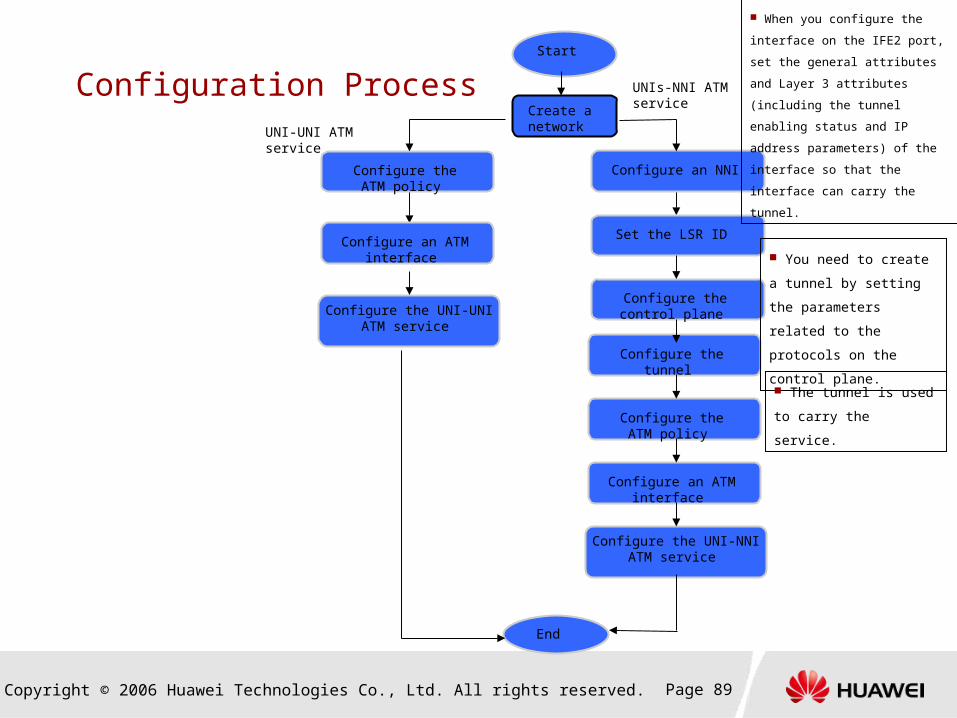
Configuration Process Start
Create a network
Configure the UNI-UNI ATM service
Configure the control plane
Configure the tunnel
Configure the UNI-NNI ATM service
End
UNI-UNI ATM service
UNIs-NNI ATM service
Configure the ATM policy
Configure an ATM interface
Configure an NNI
Set the LSR ID
Configure the ATM policy
Configure an ATM interface
When you configure the interface
on the IFE2 port, set the general
attributes and Layer 3 attributes
(including the tunnel enabling status
and IP address parameters) of the
interface so that the interface can
carry the tunnel.
You need to create a
tunnel by setting the
parameters related to the
protocols on the control
plane.
The tunnel is used to
carry the service.
Copyright © 2006 Huawei Technologies Co., Ltd. All rights reserved. Page 90
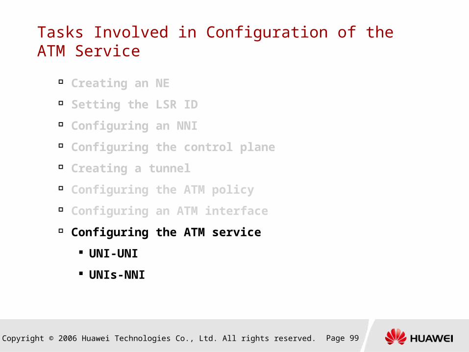
Tasks Involved in Configuration of the ATM Service
Creating an NE
Setting the LSR ID
Configuring an NNI
Configuring the control plane
Creating a tunnel
Configuring the ATM policy
Configuring an ATM interface
Configuring the ATM service
UNI-UNI
UNIs-NNI

Copyright © 2006 Huawei Technologies Co., Ltd. All rights reserved. Page 91
Configuring the ATM Policy

Copyright © 2006 Huawei Technologies Co., Ltd. All rights reserved. Page 92
Configuring the ATM Policy
Policy ID: You can enter a policy ID or select
Automatically Assign.
Policy Name: You can select one from the five
ATM policy names in the drop-down list or enter a
policy name.
Set the Service Type and Traffic Type parameters
according to the network planning.
Set the traffic descriptor according to the traffic
type.
Set the MBS (cell) and CDVT (us) parameters. In
general cases, the two parameters take the default
values.
For details about ATM policy planning and
configuration, see the Topic on QoS.
Copyright © 2006 Huawei Technologies Co., Ltd. All rights reserved. Page 93
Tasks Involved in Configuration of the ATM Service
Creating an NE
Setting the LSR ID
Configuring an NNI
Configuring the control plane
Creating a tunnel
Configuring the ATM policy
Configuring an ATM interface
Configuring the ATM service
UNI-UNI
UNIs-NNI
Copyright © 2006 Huawei Technologies Co., Ltd. All rights reserved. Page 94
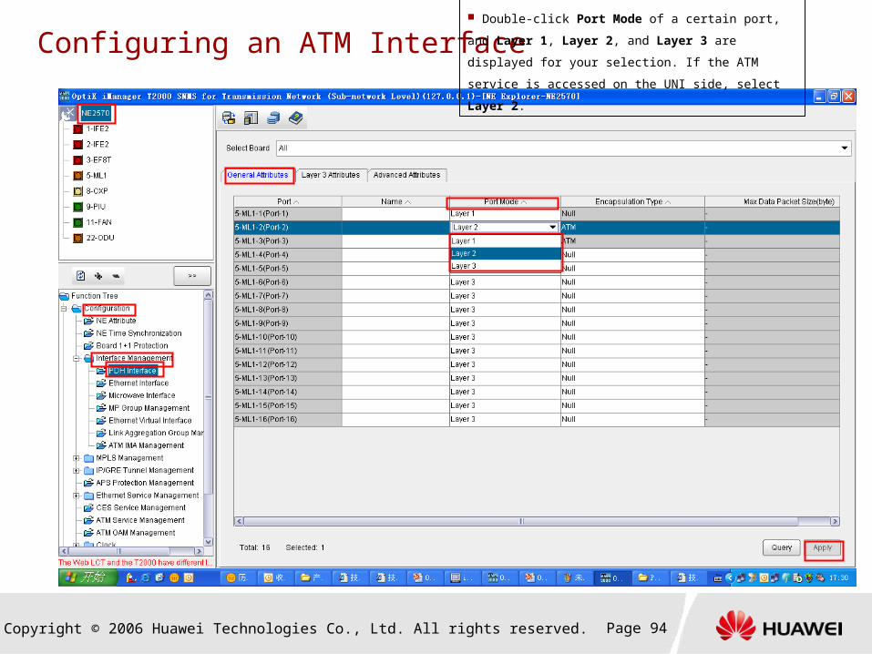
Configuring an ATM Interface Double-click Port Mode of a certain port, and Layer 1,
Layer 2, and Layer 3 are displayed for your selection. If the
ATM service is accessed on the UNI side, select Layer 2.
Copyright © 2006 Huawei Technologies Co., Ltd. All rights reserved. Page 95
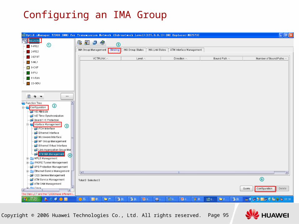
Configuring an IMA Group
①
③
②
④
⑤
⑥
Copyright © 2006 Huawei Technologies Co., Ltd. All rights reserved. Page 96
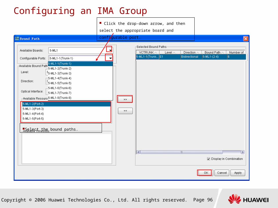
Configuring an IMA Group Click the drop-down arrow, and then select the
appropriate board and configurable port.
Select the bound paths.

Copyright © 2006 Huawei Technologies Co., Ltd. All rights reserved. Page 97
Configuring an IMA Group
Enable the port where the IMA group is created.
According to the network planning, the IMA Protocol Version, IMA Symmetry Mode, Maximum Delay Between Links, Minimum Nu
mber of Active Transmitting Links, and Minimum Number of Active Receiving Links parameter should be set the same as the param
eters set on the NodeB.
Copyright © 2006 Huawei Technologies Co., Ltd. All rights reserved. Page 98
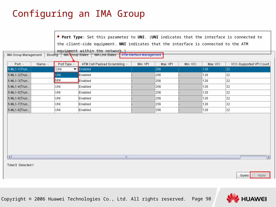
Configuring an IMA Group
Port Type: Set this parameter to UNI. (UNI indicates that the interface is connected to the client-side equipment. NNI
indicates that the interface is connected to the ATM equipment within the network.)
Copyright © 2006 Huawei Technologies Co., Ltd. All rights reserved. Page 99
Tasks Involved in Configuration of the ATM Service
Creating an NE
Setting the LSR ID
Configuring an NNI
Configuring the control plane
Creating a tunnel
Configuring the ATM policy
Configuring an ATM interface
Configuring the ATM service
UNI-UNI
UNIs-NNI
Copyright © 2006 Huawei Technologies Co., Ltd. All rights reserved. Page 100
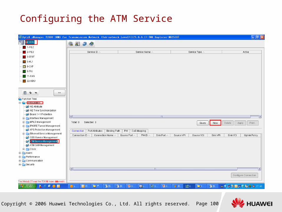
Configuring the ATM Service

Copyright © 2006 Huawei Technologies Co., Ltd. All rights reserved. Page 101
Creating the UNI-UNI ATM Service on a Per-NE Basis
Set the Service ID and Service Name parameters according to
the network planning.
Set the Service Type parameter to UNI-UNI.
Set the Connection Type parameter to PVP. In this case, only
the VPI value of the ATM connection can be modified. If the Connection Type parameter is set to PVC, the VPI and VCI values of the ATM connection can be modified.
Copyright © 2006 Huawei Technologies Co., Ltd. All rights reserved. Page 102
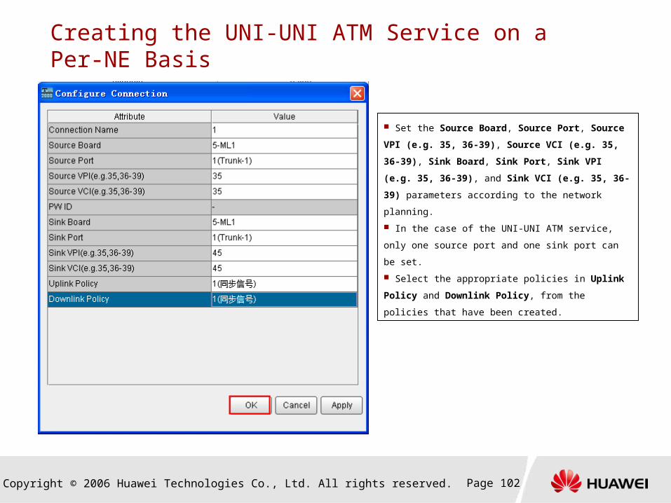
Creating the UNI-UNI ATM Service on a Per-NE Basis
Set the Source Board, Source Port, Source VPI (e.g.
35, 36-39), Source VCI (e.g. 35, 36-39), Sink Board, Sink
Port, Sink VPI (e.g. 35, 36-39), and Sink VCI (e.g. 35, 36-
39) parameters according to the network planning.
In the case of the UNI-UNI ATM service, only one source
port and one sink port can be set.
Select the appropriate policies in Uplink Policy and
Downlink Policy, from the policies that have been created.
Copyright © 2006 Huawei Technologies Co., Ltd. All rights reserved. Page 103
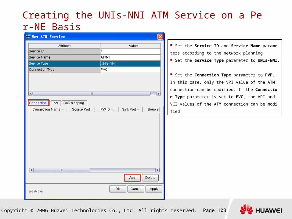
Creating the UNIs-NNI ATM Service on a Per-NE Basis
Set the Service ID and Service Name parameters accordi
ng to the network planning.
Set the Service Type parameter to UNIs-NNI.
Set the Connection Type parameter to PVP. In this case,
only the VPI value of the ATM connection can be modified. If
the Connection Type parameter is set to PVC, the VPI and
VCI values of the ATM connection can be modified.
Copyright © 2006 Huawei Technologies Co., Ltd. All rights reserved. Page 104
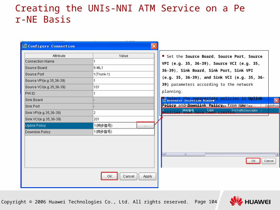
Creating the UNIs-NNI ATM Service on a Per-NE Basis
Set the Source Board, Source Port, Source VPI (e.g.
35, 36-39), Source VCI (e.g. 35, 36-39), Sink Board, Sink
Port, Sink VPI (e.g. 35, 36-39), and Sink VCI (e.g. 35, 36-
39) parameters according to the network planning.
Select the appropriate policies in Uplink Policy and
Downlink Policy, from the policies that have been created.

Copyright © 2006 Huawei Technologies Co., Ltd. All rights reserved. Page 105
Creating the UNIs-NNI ATM Service on a Per-NE Basis
Set the PW ID, PW Signaling Type, and PW Type
parameters according to the network planning. The PW type
should correspond to the connection type. In addition, when
the Connection Type parameter is set to PVP or PVC, the
encapsulation can be of the 1:1 or N:1 type.
Set the PW Encapsulation Type, PW Ingress
Label/Source Port, PW Egress Label/Sink Port, and
Tunnel Type parameters according to the network planning.
Copyright © 2006 Huawei Technologies Co., Ltd. All rights reserved. Page 106
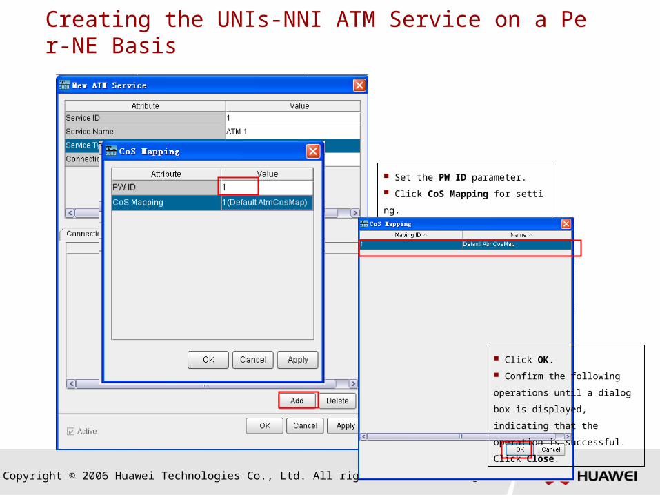
Creating the UNIs-NNI ATM Service on a Per-NE Basis
Set the PW ID parameter.
Click CoS Mapping for setting.
Click OK.
Confirm the following operations
until a dialog box is displayed,
indicating that the operation is
successful. Click Close.

Copyright © 2006 Huawei Technologies Co., Ltd. All rights reserved. Page 107
Summary
Types of Services on the OptiX RTN 900
Configuration Processes of Different Services
Configuration of Different Services on the OptiX RTN 900

www.huawei.com
Thank You


