Page 1
School of Electronic, Communication and Electrical Engineering BEng Final Year Project Report
0
FEI GAO/ Torque control for the brushless ac motor based on blackfin
UNIVERSITY OF HERTFORDSHIRE
Faculty of Engineering & Information Sciences
School of Electronic, Communication and Electrical
Engineering
BACHELOR OF ENGINEERING DEGREE WITH
HONOURS IN
ELECTRICAL AND ELECTRONIC ENGINEERING
Final Year Project Report
Torque control for the brushless ac motor based on
blackfin
Report by
GAO FEI
Supervisor
George Pissanidis
Date
APRIL 2010
Page 2
School of Electronic, Communication and Electrical Engineering BEng Final Year Project Report
1
FEI GAO/ Torque control for the brushless ac motor based on blackfin
DECLARATION STATEMENT
I certify that the work submitted is my own and that any material derived or quoted
from the
published or unpublished work of other persons has been duly acknowledged (ref.
UPR
AS/C/6.1, Appendix I, Section 2 – Section on cheating and plagiarism)
Student Full Name: FEI GAO
Student Registration Number: 08199095
Signed: …………………………………………………
Date: 13 April 2008
Page 3
School of Electronic, Communication and Electrical Engineering BEng Final Year Project Report
2
FEI GAO/ Torque control for the brushless ac motor based on blackfin
ABSTRACT
This project is based on three phase brushless AC motor (BACM) on
Blackfin, using visual DSP++ with C programming to control it. Field
Orientated Control of 3-Phase AC-Motors is discussed. The BACM
current control modules are used in programming. Pulse Width
Modulation (PWM), A/D converter and inverter are also illustrated. The
C programming code is written by software named visual DSP++ 5.0 to
control operation. Some research and analysis of hardware components
are explained. Finally, the program is fine tuned for improvement and the
possibility of further development assessed.
Page 4
School of Electronic, Communication and Electrical Engineering BEng Final Year Project Report
3
FEI GAO/ Torque control for the brushless ac motor based on blackfin
ACKNOWLEDGEMENTS
I would like to thank my project supervisor George Pissanidis for his
unconditional technical support and guidance throughout. Although I
have studied the issue very slow, he patiently helped me.
Page 5
School of Electronic, Communication and Electrical Engineering BEng Final Year Project Report
4
FEI GAO/ Torque control for the brushless ac motor based on blackfin
TABLE OF CONTENTS
DECLARATION STATEMENT ................................................................1
ABSTRACT................................................................................................2
ACKNOWLEDGEMENTS........................................................................3
TABLE OF CONTENTS............................................................................4
LIST OF FIGURES ....................................................................................7
GLOSSARY ...............................................................................................9
1. Introduction.........................................................................................10
1.1 Aims and objectives......................................................................10
1.2 Background...................................................................................10
1.3 overview of project work..............................................................11
2. Background Theory ............................................................................11
2.1 Brushless AC motor......................................................................11
2.1.1 theory of brushless AC motor..............................................11
2.1.2 Advantage of brushless AC motor .......................................13
2.2 PWM unit......................................................................................14
2.2.1 Theory of PWM...................................................................15
2.3 A/D converter................................................................................16
2.4 Inverter..........................................................................................17
2.5 PID controller theory ....................................................................17
Page 6
School of Electronic, Communication and Electrical Engineering BEng Final Year Project Report
5
FEI GAO/ Torque control for the brushless ac motor based on blackfin
3. Field Orientated Control of 3-Phase AC-Motor [5]............................18
3.1 Space Vector definition and projection.........................................19
3.1.1 (a,b,c) →(α,β) (the Clarke transformation) .........................20
3.1.2 (a,b) →(d,q) (the Park transformation)................................21
3.1.3 (a,b) →(d,q) (inverse Park transformation).........................21
3.2 The basic scheme for the FOC......................................................22
3.3 The input for the FOC...................................................................23
3.3.1 current sampling ..................................................................23
3.3.2 Rotor flux position...............................................................23
4. BACM current control modules .........................................................25
5. Design .................................................................................................27
6. Programming ......................................................................................28
6.1 S function model code ..................................................................28
6.2 Main comments.............................................................................30
7. Results.................................................................................................31
7.1 initialization process .....................................................................32
7.2 speed control .................................................................................33
7.3 position control .............................................................................34
8. Conclusion and further development..................................................34
8.1 Further development .....................................................................35
9. Projection time plan ............................................................................36
Page 7
School of Electronic, Communication and Electrical Engineering BEng Final Year Project Report
6
FEI GAO/ Torque control for the brushless ac motor based on blackfin
10.References............................................................................................37
Page 8
School of Electronic, Communication and Electrical Engineering BEng Final Year Project Report
7
FEI GAO/ Torque control for the brushless ac motor based on blackfin
LIST OF FIGURES
Figure 1 sample brushless motor ........................................................12
Figure 2 PWM signals [2]...................................................................14
Figure 3 A/D converter chip [3]..........................................................16
Figure 4 Basic scheme of 3-phase inverter and AC motor [5] ...........17
Figure 5 PID controller [6] .................................................................17
Figure 6 Stator current space vector and its component in (a,b,c) .....19
Figure 7 Stator current space vector and its components in (a,b) ......20
Figure 8 Stator current space vector and its component in (a,b) and in
the d,q rotating reference frame....................................................21
Figure 9 Basic scheme of FOC for AC-motor....................................22
Figure 10 motor control systems ........................................................22
Figure 11 Current, voltage and rotor flux space vectors in the d,q
rotating reference frame and their relationship with a,b,c and α,β
stationary reference frame ............................................................24
Figure 12 Block diagram of the BACM torque control .....................25
Figure 13 the block diagram (a)............................................................0
Figure 14 the block diagram (b) ...........................................................0
Figure 15 current trajectories of vector control in initialization.........32
Figure 16 Speed command, actual speed waveform ..........................33
Page 9
School of Electronic, Communication and Electrical Engineering BEng Final Year Project Report
8
FEI GAO/ Torque control for the brushless ac motor based on blackfin
Figure 17 waveform of position command, the actual location .........34
Figure 18 project time plan.................................................................36
Page 10
School of Electronic, Communication and Electrical Engineering BEng Final Year Project Report
9
FEI GAO/ Torque control for the brushless ac motor based on blackfin
GLOSSARY
A/DC Analog to Digital Converter
BACM Brushless AC Motor
BLDC Brushless DC Motor
FOC Field Orientated Control
PID control Proportion, Integration, Differentiation
PS Position sensor
PWM Pulse Width Modulation
Page 11
School of Electronic, Communication and Electrical Engineering BEng Final Year Project Report
10
FEI GAO/ Torque control for the brushless ac motor based on blackfin
1. Introduction
This report mainly illustrates my final year project, it is torque control for the
brushless AC motor based on blackfin. This project is based on Digital Signal
Processing(DSP).The basic theory behind electronic motor controls is that the motor’s
speed, torque, and direction are managed by electronically switching or modulating
the voltages to the motor. The current level to the motor can also be managed
indirectly by modulating the motor’s voltage.
1.1 Aims and objectives
The aim of project is to develop torque control for the brushless ac motor based on
BlackFin and create a software environment for AC motor control. The project is
written by C programming and design software mainly.
The objective of project is to develop A/DC driver and vector control algorithm.
Analog-digital converter, ADC for short is a device that the analog is converted to
digital. In the computer control system, should be checked to a variety of testing
devices. Continuously variable voltage or current as analog provide controlled object
of related parameters (such as speed, pressure, temperature, etc.) and control. The
input of computer should be the digital, so it need ADC to control.
1.2 Background
In recent years, brushless motor in the rapid development in the field model is a kind
of motivation. Because of the price, yield and over the past few years brushless motor
used in high-grade aviation model due to mechanical processing technology, now the
rapid development, the production cost of brushless motors dropped many, it is into
every aspect of field model from the electric control, electric car to remote-controlled
boats to electric model plane, everywhere.
Electric power electronics, electrical technology, the controller for the development of
technology progress of electromechanical industry provides a powerful force. And
often used in motor control are compared, the MCU control motor of brushless dc
motor (BLDC) motors and eliminate the phase change brush wear, improve the arc
stability of the control system and the life, power electronics device applications
greatly reduced the size of the control system, the control structure in industrial and
civil widely used in the field and the server application prospect
Page 12
School of Electronic, Communication and Electrical Engineering BEng Final Year Project Report
11
FEI GAO/ Torque control for the brushless ac motor based on blackfin
1.3 overview of project work
Chapter 1 provides background material on brushless AC motor. Chapter 2 describes
theoretical analysis of how each component works. Chapter 3 provides theoretical
analysis and measurement of Field Orientated Control of 3-Phase AC-Motors.
Chapter 4 describes BACM current control modules in details. Chapter 5 has given
the some programming and comments. Chapter 6 presents the some results. Chapter 7
provides conclusions and further work.
2. Background Theory
2.1 Brushless AC motor
2.1.1 theory of brushless AC motor
Motor is electrical equipment that converted into electrical energy to mechanical
energy, and can re-use of machinery to produce kinetic energy, used to drive other
devices.
The following figure shows the theory of brushless motor simply
Page 13
School of Electronic, Communication and Electrical Engineering BEng Final Year Project Report
12
FEI GAO/ Torque control for the brushless ac motor based on blackfin
Figure 1 sample brushless motor
Three coils are mounted 120 degrees apart. When current is applied to a coil it will
attract the nearest rotor magnet. If current is applied to the phase U coil, the rotor will
turn clockwise until magnet A is aligned with the coil (at a detent). This simple
brushless motor is similar to a how a stepper motor operates; turning on one coil will
cause the shaft to rotate by one magnet pole. [1]
Three-phase asynchronous motor to rotate together with the prerequisite is a rotating
magnetic field, the three-phase asynchronous motor stator windings is used to produce
a rotating magnetic field. We know, but in power phase-to-phase voltage difference in
phase is 120 degrees, three-phase asynchronous motor stator windings in three of the
spatial position also sent 120 degrees, so each stator winding, when in tube, conduct
the three-phase power, stator winding can produce a rotating magnetic field changes
every one cycle. Current, rotating magnetic field in space, namely a rotating magnetic
rotation of rotation speed and the current changes are synchronous. Rotating magnetic
speed for: n = 60f/P type of f for power frequency magnetic poles, P is the unit is the
logarithm, n.: RPM. According to the type we know, motor speed and number of poles
and the use of power frequency, therefore, ac motor speed control, there are two ways:
1, the change pole, 2, the frequency conversion method. Before the first method,
multi-purpose now use frequency conversion technology to realize stepless speed of
ac motor control
Page 14
School of Electronic, Communication and Electrical Engineering BEng Final Year Project Report
13
FEI GAO/ Torque control for the brushless ac motor based on blackfin
2.1.2 Advantage of brushless AC motor
a. brushless and low interference
In addition to the brushless motor brush, the most immediate change is not a brush
motor running of edm, thus greatly reducing the spark of remote radio equipment.
b. Low noise and Smooth operation
Brushless motors no brush, reduce friction, the noise will run smoothly, and the
advantages of low many for the operation stability of model is a great support.
c. Long service life and low maintenance cost
Brushless motors wear primarily in the bearing, from the perspective of machinery,
brushless motor is almost a free maintenance of motor, when necessary, the need to do
some dust maintenance. A comparison, brushless motor brush motor is relative to the
advantages, but where everything is not absolute, low torque motor outstanding
performance, torque and characteristics of brushless motor is irreplaceable, but
brushless motors use convenient, as the cost of brushless controller and decline and
brushless technology development and market competition, high-speed brushless
power system is developed and popularized phase, it also has greatly promoted the
development of sports model.
Page 15
School of Electronic, Communication and Electrical Engineering BEng Final Year Project Report
14
FEI GAO/ Torque control for the brushless ac motor based on blackfin
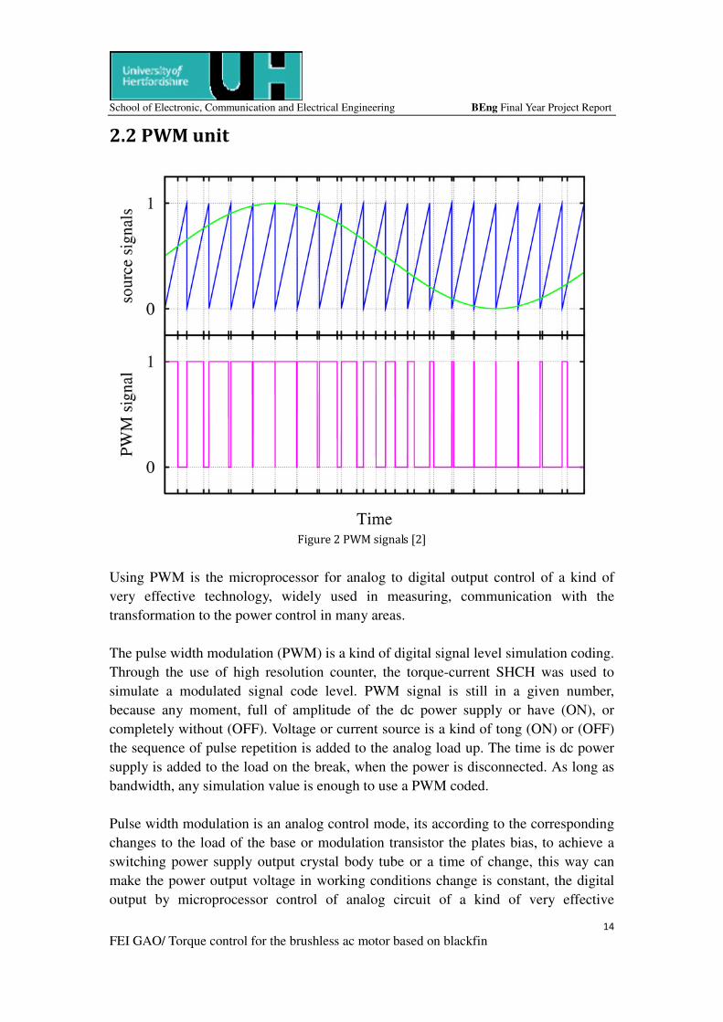
2.2 PWM unit
Figure 2 PWM signals [2]
Using PWM is the microprocessor for analog to digital output control of a kind of
very effective technology, widely used in measuring, communication with the
transformation to the power control in many areas.
The pulse width modulation (PWM) is a kind of digital signal level simulation coding.
Through the use of high resolution counter, the torque-current SHCH was used to
simulate a modulated signal code level. PWM signal is still in a given number,
because any moment, full of amplitude of the dc power supply or have (ON), or
completely without (OFF). Voltage or current source is a kind of tong (ON) or (OFF)
the sequence of pulse repetition is added to the analog load up. The time is dc power
supply is added to the load on the break, when the power is disconnected. As long as
bandwidth, any simulation value is enough to use a PWM coded.
Pulse width modulation is an analog control mode, its according to the corresponding
changes to the load of the base or modulation transistor the plates bias, to achieve a
switching power supply output crystal body tube or a time of change, this way can
make the power output voltage in working conditions change is constant, the digital
output by microprocessor control of analog circuit of a kind of very effective
Page 16
School of Electronic, Communication and Electrical Engineering BEng Final Year Project Report
15
FEI GAO/ Torque control for the brushless ac motor based on blackfin
technology. PWM control technology with its simple, flexible and dynamic response
good advantage and become the most extensive application of power electronic
technology, the control mode is people study hotspot nowadays. Due to the
development of science and technology has no boundaries between subjects,
combining modern control theory thoughts or achieve harmonic soft switch
technology will become the PWM control technology is one of the main development
direction.
2.2.1 Theory of PWM
The analog signals, its value can be continuous variation amplitude of time and the
resolution are no restrictions. 9V battery is an emulator, because it is the output
voltage is not precisely 9V equal, but with time changing, and desirable any real value.
Similarly, the current is absorbed from the batteries in a group may not limit value
range. Analog and digital signal of the difference between the values of usually only
belong to pre-defined possible value set, for example in the 0V, 5V set of values.
Simulation can be directly used to the voltage and current control, such as the volume
of the radio control car. In the simulation of the radio, simple volume knob is
connected to a variable resistor. When the knob screw move, bigger or smaller
resistance, The current flows through the resistance will increase or decrease, which
changed the result, to drive the speaker volume corresponding bigger or smaller. With
the radio, the analog output and input into the linear scale.
Page 17
School of Electronic, Communication and Electrical Engineering BEng Final Year Project Report
16
FEI GAO/ Torque control for the brushless ac motor based on blackfin
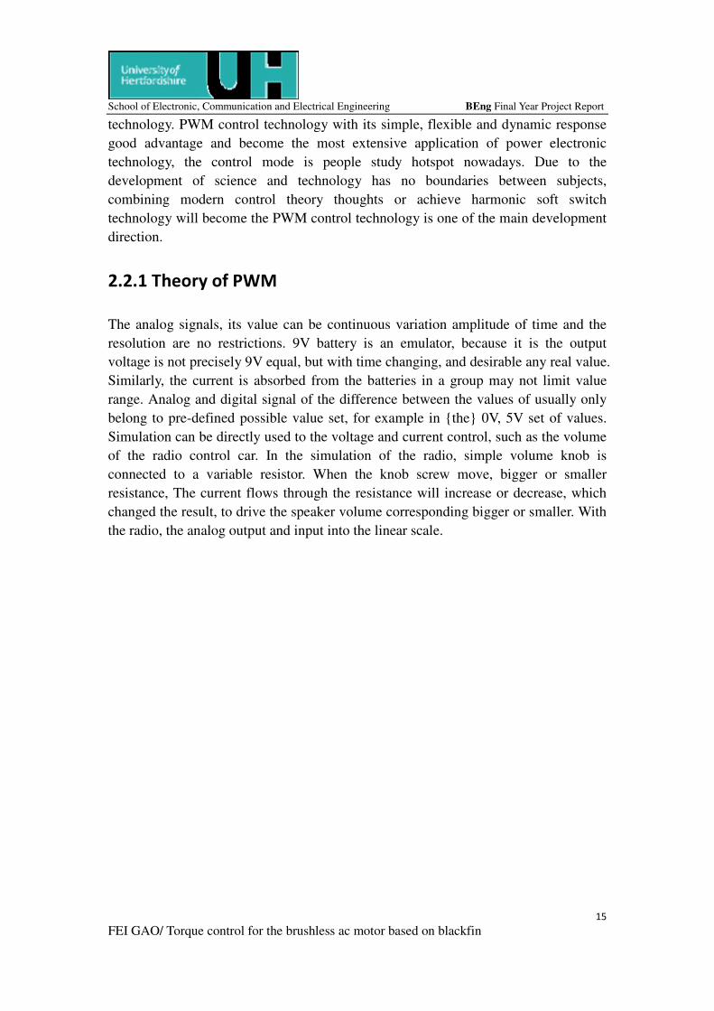
2.3 A/D converter
Figure 3 A/D converter chip [3]
An analog-to-digital converter (abbreviated ADC, A/D or A to D) is a device which
converts continuous signals to discrete digital numbers. The reverse operation is
performed by a digital-to-analog converter (DAC).
Typically, an ADC is an electronic device that converts an input analog voltage (or
current) to a digital number proportional to the magnitude of the voltage or current.
However, some non-electronic or only partially electronic devices, such as rotary
encoders, can also be considered ADCs. The digital output may use different coding
schemes, such as binary, Gray code or two's complement binary. [4]
Page 18
School of Electronic, Communication and Electrical Engineering BEng Final Year Project Report
17
FEI GAO/ Torque control for the brushless ac motor based on blackfin
2.4 Inverter
Figure 4 Basic scheme of 3-phase inverter and AC motor [5]
The direct current (DC) transform into an alternating current (AC), its scientific terms
for the device inverter. Due to the change of frequency equipment or frequency
voltage inverter main device called ", "the product itself was named" inverter
".Usually, the voltage and frequency fixed ac frequency conversion variable voltage
or for the device called the ac inverter ".
In order to produce variable voltage and frequency converter (Inverter) must first turn
power an alternating current (AC) transform for the direct current (DC), the direct
current (DC) transform into an alternating current (AC). Used in motor control of
frequency converter, can change voltage and frequency of can be changed.
2.5 PID controller theory
Figure 5 PID controller [6]
Page 19
School of Electronic, Communication and Electrical Engineering BEng Final Year Project Report
18
FEI GAO/ Torque control for the brushless ac motor based on blackfin
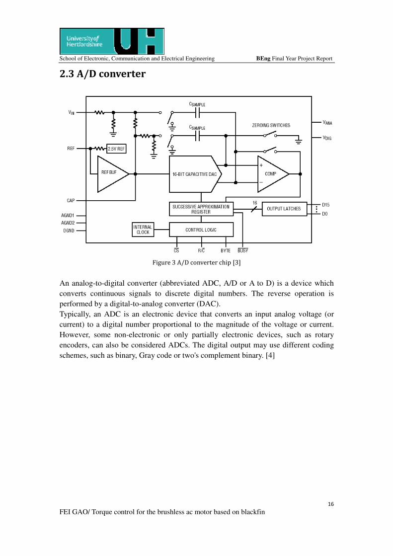
PID (proportional - integral - derivative) controller as the first practical use of the
controller has 50 years of history, is still the most widely used industrial controller.
PID controller is easy to understand, the use of accurate system models without
preconditions, thus to become the most widely used controller.
PID controller by the ratio of unit (P), integral unit (I) and the differential unit (D)
component. The input e (t) and output u (t) of the relationship
So its transfer function
Where the proportional coefficient Kp; TI for the integral time constant; TD for the
differential time constant
It is as versatile and flexible in use, there are series products, the use of only three
parameters to set (Kp, Ti and Td) can be. In many cases, does not necessarily need all
three elements, which can take one to two units, the ratio control unit is essential.
First, PID has wide range of applications. Although many industrial processes are
nonlinear or time-varying, but can become simplified through their basic non-linear
and dynamic characteristics of the system over time, this PID can be controlled.
Secondly, PID parameter tune easier. That is PID parameters Kp, Ti and Td according
to the dynamic nature of the process of setting time. If the process is dynamic,
changing, for example, changes may be caused by the load change in system
dynamics, PID parameters can be re-tuning.
Third, PID controller in practice also constantly improved
3. Field Orientated Control of 3-Phase
AC-Motor [5]
The Field Orientated Control (FOC) consists of controlling the stator currents
represented by a vector. This control is based on projections which transform a three
Page 20
School of Electronic, Communication and Electrical Engineering BEng Final Year Project Report
19
FEI GAO/ Torque control for the brushless ac motor based on blackfin
phase time and speed dependent system into a two co-ordinate (d and q co-ordinates)
time invariant system. These projections lead to a structure similar to that of a DC
machine control. Field orientated controlled machines need two constants as input
references: the torque component (aligned with the q co-ordinate) and the flux
component (aligned with d co-ordinate)
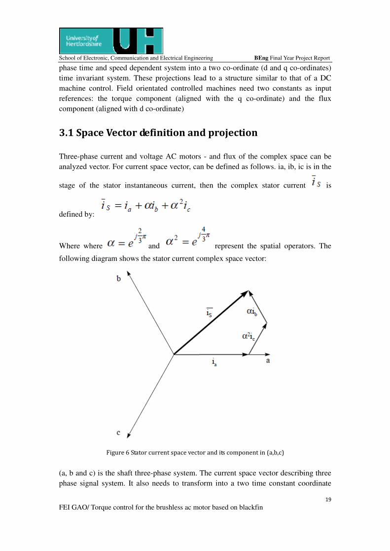
3.1 Space Vector definition and projection
Three-phase current and voltage AC motors - and flux of the complex space can be
analyzed vector. For current space vector, can be defined as follows. ia, ib, ic is in the
stage of the stator instantaneous current, then the complex stator current is
defined by:
Where where and represent the spatial operators. The
following diagram shows the stator current complex space vector:
Figure 6 Stator current space vector and its component in (a,b,c)
(a, b and c) is the shaft three-phase system. The current space vector describing three
phase signal system. It also needs to transform into a two time constant coordinate
Page 21
School of Electronic, Communication and Electrical Engineering BEng Final Year Project Report
20
FEI GAO/ Torque control for the brushless ac motor based on blackfin
system.
(a,b,c) →(α,β) (the Clarke transformation) which outputs a two co-ordinate time
variant
system
(a,b) →(d,q) (the Park transformation) which outputs a two co-ordinate time invariant
System
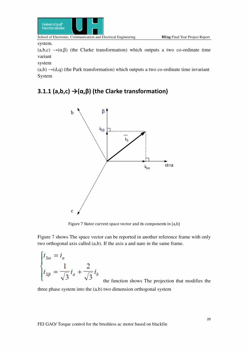
3.1.1 (a,b,c) →(α,β) (the Clarke transformation)
Figure 7 Stator current space vector and its components in (a,b)
Figure 7 shows The space vector can be reported in another reference frame with only
two orthogonal axis called (a,b). If the axis a and αare in the same frame.
the function shows The projection that modifies the
three phase system into the (a,b) two dimension orthogonal system
Page 22
School of Electronic, Communication and Electrical Engineering BEng Final Year Project Report
21
FEI GAO/ Torque control for the brushless ac motor based on blackfin
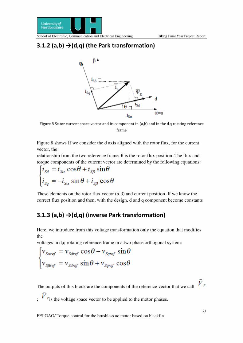
3.1.2 (a,b) →(d,q) (the Park transformation)
Figure 8 Stator current space vector and its component in (a,b) and in the d,q rotating reference
frame
Figure 8 shows If we consider the d axis aligned with the rotor flux, for the current
vector, the
relationship from the two reference frame. θ is the rotor flux position. The flux and
torque components of the current vector are determined by the following equations:
These elements on the rotor flux vector (α,β) and current position. If we know the
correct flux position and then, with the design, d and q component become constants
3.1.3 (a,b) →(d,q) (inverse Park transformation)
Here, we introduce from this voltage transformation only the equation that modifies
the
voltages in d,q rotating reference frame in a two phase orthogonal system:
The outputs of this block are the components of the reference vector that we call
; is the voltage space vector to be applied to the motor phases.
Page 23
School of Electronic, Communication and Electrical Engineering BEng Final Year Project Report
22
FEI GAO/ Torque control for the brushless ac motor based on blackfin
3.2 The basic scheme for the FOC
Figure 9 Basic scheme of FOC for AC-motor
Figure 10 motor control systems
Page 24
School of Electronic, Communication and Electrical Engineering BEng Final Year Project Report
23
FEI GAO/ Torque control for the brushless ac motor based on blackfin
In all sorts of vector control methods, we use an indirect crucial. But only one control
method, the measurement and processing of motor rotor model parameter is the time
constant Lr/Rr (in turn bad estimation is module). If the motor is a permanent magnet
synchronous motor, structure diagram and the corresponding function will be very
similar, no longer need to turn bad estimation, flux command can be set to zero
(magnets have their own flux). This work is part of the algorithm for calculating the
voltage level: must convert volts and ampere. As in any modern power electronics
system, the motor control system by muscle (power converter) and the brain (SCM).
Driving power converter (known as inverter) is driven by three PWM output. In figure
9, it is easy to see a powerful way to a buffer 3 0-5 v into a signal, the logic of the
pulse signal 300V - 0, to exert motor terminal. Motor winding inductors played a
low-pass filter function: remove the carrier frequency, smooth current changes,
forming a sine wave, namely the PWM waveform.
Let us begin from a advanced CPU one motor drive system overall demand. The
vector control algorithm for calculating, and must be in 1 ~ 10 calculation speed
between 1ms (kHz to 100 mu s time, depending on the final closed-loop application
of bandwidth. System requires a lot of mathematics calculation (triangle function, PID
regulator, real-time flux and the torque motor parameter estimation based on). In
addition, must give the rest of the application (communication, the user interface, etc.)
of computing conservatives. In order not to limit dynamic performance, the main
control variables to the lowest 16, the precision of intermediate results need 32-bit
computing power.
3.3 The input for the FOC
Fundamental requirements for the FOC are a knowledge of two phase currents (as the
motor is star-connected, the third phase current is also known, since ia + ib + ic = 0 ),
and the rotor flux position.
3.3.1 current sampling
Measurement of three-phase current Ia and Ib, and a sampling A / D converter to
convert. FOC work correctly depends on the real current measurement.
3.3.2 Rotor flux position
Position of the rotor flux field oriented control of knowledge is the core. . In fact if
Page 25
School of Electronic, Communication and Electrical Engineering BEng Final Year Project Report
24
FEI GAO/ Torque control for the brushless ac motor based on blackfin
there is an error in this variable the rotor flux is not aligned with d-axis and iSd and
iSq are incorrect flux and torque components of the stator current. The following
figure shows (a, b, c), (α, β) and (d, q) frame of reference, and the correct position the
rotor flux, stator current and stator voltage space vector rotating with d, q refer to the
synchronization Speed.
Figure 11 Current, voltage and rotor flux space vectors in the d,q rotating reference frame and
their relationship with a,b,c and α,β stationary reference frame
Measure the rotor flux position is different, if we consider the synchronous or
asynchronous motors.
Synchronous machine in various parts of the rotational speed is equal to the speed of
rotor flux. Then Q (rotor flux position) is directly measured by the position sensor or
rotor speed integration.
Induction machine in various parts of the rotor speed is not equal to the rotor flux
speed (with a sliding speed), it requires a special method to calculate the basic
question is the current model, the model equations requires two motors in the use of
D , q coordinate system.
Page 26
School of Electronic, Communication and Electrical Engineering BEng Final Year Project Report
25
FEI GAO/ Torque control for the brushless ac motor based on blackfin
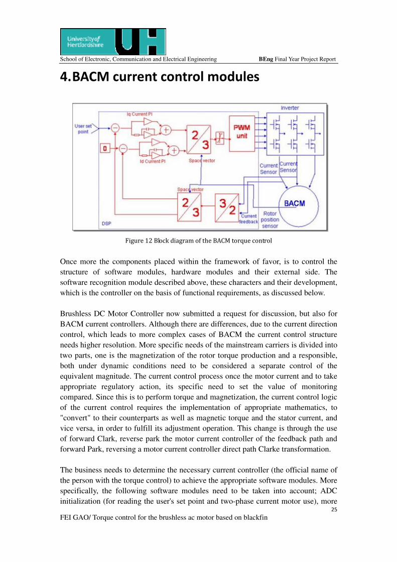
4. BACM current control modules
Figure 12 Block diagram of the BACM torque control
Once more the components placed within the framework of favor, is to control the
structure of software modules, hardware modules and their external side. The
software recognition module described above, these characters and their development,
which is the controller on the basis of functional requirements, as discussed below.
Brushless DC Motor Controller now submitted a request for discussion, but also for
BACM current controllers. Although there are differences, due to the current direction
control, which leads to more complex cases of BACM the current control structure
needs higher resolution. More specific needs of the mainstream carriers is divided into
two parts, one is the magnetization of the rotor torque production and a responsible,
both under dynamic conditions need to be considered a separate control of the
equivalent magnitude. The current control process once the motor current and to take
appropriate regulatory action, its specific need to set the value of monitoring
compared. Since this is to perform torque and magnetization, the current control logic
of the current control requires the implementation of appropriate mathematics, to
"convert" to their counterparts as well as magnetic torque and the stator current, and
vice versa, in order to fulfill its adjustment operation. This change is through the use
of forward Clark, reverse park the motor current controller of the feedback path and
forward Park, reversing a motor current controller direct path Clarke transformation.
The business needs to determine the necessary current controller (the official name of
the person with the torque control) to achieve the appropriate software modules. More
specifically, the following software modules need to be taken into account; ADC
initialization (for reading the user's set point and two-phase current motor use), more
Page 27
School of Electronic, Communication and Electrical Engineering BEng Final Year Project Report
26
FEI GAO/ Torque control for the brushless ac motor based on blackfin
logical unity feedback control system (which is a unique, When the feedback is
negative, a summer feedback is positive, if in the power plant), compensator, reverse /
forward the changes Park and Clark, with the PWM unit interface logic and the PWM
unit initialization. Each of these software modules discussed in detail the following.
Such as ADC, more logical, compensation, interface logic and PWM initialization
discussed under the brushless DC motor of software modules and logic has not
changed, because they are even in the BACM software module, there is no need to
further negotiations. As for the case forward / reverse conversion Software Park and
Clark module, which by the appropriate command (program) through software
programs to achieve their mathematical equivalent transformation process.
Differences in sampling a current feedback is the fact that there is a consideration in
the BACM three current brushless DC motor in a single case against the current
monitoring (one for each phase) the need. However, because every time a balanced
three-phase systems (particularly true in the case of point, there is no connection
among other places), and currents into the system and is always zero (any current
value into the system, leaving the system), there is need to monitor only two or three a
current of. On the following formula can be derived from the value of the third
A successful derivation of the third current special consideration is to avoid any offset
in the sampling process, it is possible just by following the procedures for a complete
discussion (based on hardware sensor interface module and the ADC's offset program
in its initial zero software module).
The software module the following order: first, ADC sampling the user's set point and
two three motor currents. Second, the calculation of the third current and rotor
position readings. Once these software modules, thus completing their feed value
(three-phase current and rotor position) of the forward and reverse current of Clark 'in
transition, in the torque and the three-phase DC components of the extraction results
of combined experience of the current park software modules motor. The following
software modules is more, this is the implementation of the torque current component
and the user's set point, once more for the DC component of zero set point (the reason
for its implementation is in a lower note). Each of them in turn feed compensator
module (which again is executed twice). The output of the two modules to
compensation, feed forward and reverse park Clarke software modules to the
equivalent components into a three-phase direct torque and current commands.
Following Clark, the former parks and reverse scaling software modules into the logic
module output, so that the inside of the unit where the supply of PWM control cycle
3-phase voltage motors by summing up the equivalent scope of the inverter.
Page 28
School of Electronic, Communication and Electrical Engineering BEng Final Year Project Report
27
FEI GAO/ Torque control for the brushless ac motor based on blackfin
The last one, more consideration is a voltage source inverter as the servo amplifier.
The reason is due to the fact that, when an inductive load such as motor () is fed by a
voltage source and load currents through this phase without applied voltage. Because
it appears from the above idea, the torque for the controller stage of the successful
implementation of current control and high accuracy. The whole process becomes
more complicated when the applied voltage changes the frequency is, as it is in a year,
itself and the corresponding result of changes in the current phase. To compensate for
this phase of the magnetization transfer (or direct) current adjustment control has been
added in the control structure, it is given a value of zero set point. In this way, the
control structure can compensate for the voltage and current between the phases
differences caused by, because it may take appropriate action to zero magnetization
current.
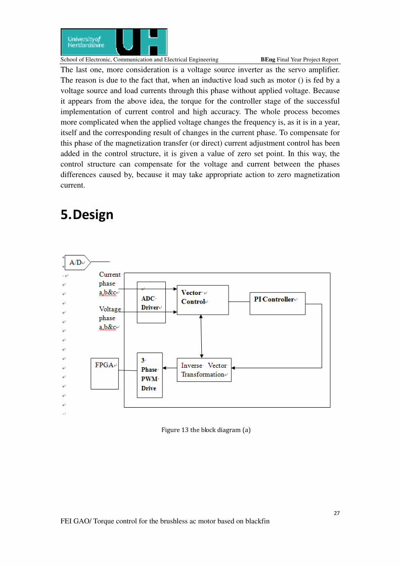
5. Design
Figure 13 the block diagram (a)
Page 29
School of Electronic, Communication and Electrical Engineering BEng Final Year Project Report
28
FEI GAO/ Torque control for the brushless ac motor based on blackfin
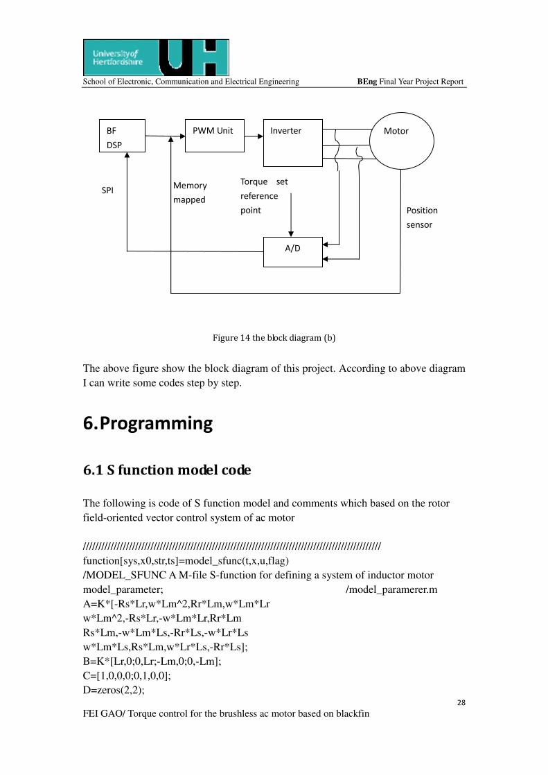
The above figure show the block diagram of this project. According to above diagram
I can write some codes step by step.
6. Programming
6.1 S function model code
The following is code of S function model and comments which based on the rotor
field-oriented vector control system of ac motor
/////////////////////////////////////////////////////////////////////////////////////////////////
function[sys,x0,str,ts]=model_sfunc(t,x,u,flag)
/MODEL_SFUNC A M-file S-function for defining a system of inductor motor
model_parameter; /model_paramerer.m
A=K*[-Rs*Lr,w*Lm^2,Rr*Lm,w*Lm*Lr
w*Lm^2,-Rs*Lr,-w*Lm*Lr,Rr*Lm
Rs*Lm,-w*Lm*Ls,-Rr*Ls,-w*Lr*Ls
w*Lm*Ls,Rs*Lm,w*Lr*Ls,-Rr*Ls];
B=K*[Lr,0;0,Lr;-Lm,0;0,-Lm];
C=[1,0,0,0;0,1,0,0];
D=zeros(2,2);
Figure 14 the block diagram (b)
BF
DSP
PWM Unit Inverter Motor
A/D
Position
sensor
Torque set
reference
point
Memory
mapped SPI
Page 30
School of Electronic, Communication and Electrical Engineering BEng Final Year Project Report
29
FEI GAO/ Torque control for the brushless ac motor based on blackfin
/
/dispatch the flag
/
switch flag,
case 0
[sys,x0,str,ts]=mdlInitializeSizes; / Initialization
case 1
sys=mdlDerivatives(t,x,u); /Calculate derivatives
case 3
sys=mdlOutputs(t,x,u); / Calculate outputs
case2,4,9
sys=[ ]; /Unused flags
otherwise
error(['Unhandled flag=',num2str(flag)]); /Error handling
end /end model_sfunc
/
/ mdlInitializeSizes
/ Return the sizes, initial conditions, and sample times for the S-function.
/
function [sys,x0,str,ts]=mdlInitializeSizes
sizes=simsizes;
sizes.NumContStates=5;
Sizes.NumDiscStates=0;
Sizes.NumOutputs=6;
Sizes.NumInputs=3;
Sizes.DirFeedthrough=1; /Matrix D is nonempty
Sizes.NumSampleTimes=1;
sys=simsizes(sizes);
x0=[ 1.800,6.530,-2.350,-0.970,600 ]; % initialize the initial conditions
str=[] ; /str is an empty matrix.
Ts=[0,0] / Initialize the array of sample times
/end mdlInitializeSizes
/
/ mdlDerivatives Return the derivatives for the continuous ststes.
/
function sys=mdlDerivatives(t,x,u)
Sys(1:4)=A*X(1:4)+B*u;
Te=np*Lm*(X(2)*X(3)-X(4)*X(1));
w=X(5);
Sys(5)=((Te-u(3))*np-D*X(5))/J;
/ end mdlDerivatives.
/
Page 31
School of Electronic, Communication and Electrical Engineering BEng Final Year Project Report
30
FEI GAO/ Torque control for the brushless ac motor based on blackfin
/ mdlOutputs Return the block outputs
/
Function sys=mdlOutputs(t,x,u)
sys(1:2)=X(1:2);
sys(3)=Ls*X(1)+Lm*X(3);
sys(4)=Ls*X(2)+Lm*X(4);
sys(5)=X(5);
sys(6)=np*Lm*(X(2)*X(3)-X(4)*X(1));
/ end mdlOutputs.
[model_parameter.m]
Rs=0.687; / stator resistance(Ω)
Rr=0.642; / rotor resistance(Ω)
Ls=0.084; / stator inductance(H)
Lr=0.852; / rotor inductance(H)
Lm=0.813; / mutual inductance(h)
W=1400; / real speed(rpm)
Np=2; / pole number
J=0.3; / moment of inertia(kgmm)t
D=0.01; / torque damp coefficien
K=1/(Ls*Lr-Lm*Lm);
/end
//////////////////////////////////////////////////////////////////////////////////////////////////////
6.2 Main comments
The code of this project mainly is based on the following comments.
//declare global variable for the three phase currents, stationary reference current
variables, rotating frame reference current variables.
//You will need the following functions:
//Read_adc //This is for reading the current that goes in the motor,
three phase motor thus three phases curenents need to be acquired.
//Read_position //The mechanical position of the rotor is require for the
reverse/farward Park/Clark trhansformations...
// The following transformaitons are required to convert ac to dc for
controll operations and dc to ac to drive the motor.
//Forward Park
//Reverse Park
Page 32
School of Electronic, Communication and Electrical Engineering BEng Final Year Project Report
31
FEI GAO/ Torque control for the brushless ac motor based on blackfin
//Farward Clark
//Reverse Clark
//PI_control
//Initialize adc, this is soing to be over SPI thus you will need to develope an
initialisation code for an SPI interface system.
//For now you will not have to warry about the PWM inverter as there is a need for a
memmory mapped peripheral... However you will
//need to develope code to access external memmory space
main( int argc, char *argv[] )
//Call the Initialize_adc_unit
//Call the PWM_unit_initialize
while(1)
//Call_read_adc //This is for reading currents and also the user's reference
commands.
//Call read_position
//Call the necessary Clark Park transformation READ TI PAPER
//Call PI_control
//Call the necessary oposit Clark Park transformation READ TI PAPER
//Call PWM_update
7. Results
The ideal results are three controls. It is Initialization process, Speed control and
Position Control.
Page 33
School of Electronic, Communication and Electrical Engineering BEng Final Year Project Report
32
FEI GAO/ Torque control for the brushless ac motor based on blackfin
7.1 initialization process
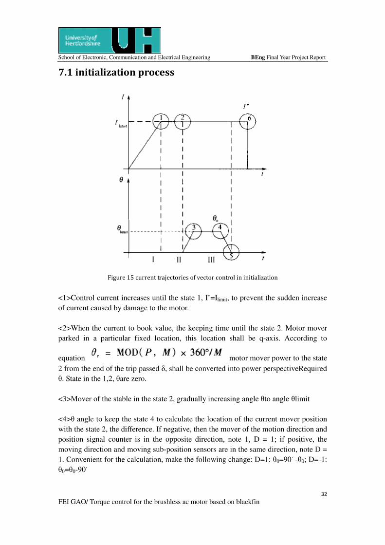
Figure 15 current trajectories of vector control in initialization
<1>Control current increases until the state 1, I’=Ilimit, to prevent the sudden increase
of current caused by damage to the motor.
<2>When the current to book value, the keeping time until the state 2. Motor mover
parked in a particular fixed location, this location shall be q-axis. According to
equation motor mover power to the state
2 from the end of the trip passed δ, shall be converted into power perspectiveRequired
θ. State in the 1,2, θare zero.
<3>Mover of the stable in the state 2, gradually increasing angle θto angle θlimit
<4>θ angle to keep the state 4 to calculate the location of the current mover position
with the state 2, the difference. If negative, then the mover of the motion direction and
position signal counter is in the opposite direction, note 1, D = 1; if positive, the
moving direction and moving sub-position sensors are in the same direction, note D =
1. Convenient for the calculation, make the following change: D=1: θ0=90。
-θ0; D=-1:
θ0=θ0-90。
Page 34
School of Electronic, Communication and Electrical Engineering BEng Final Year Project Report
33
FEI GAO/ Torque control for the brushless ac motor based on blackfin
<5><6>In turn will beθ, I’ decreases to zero. Thus, the initialization process is
completed.
7.2 speed control
Figure 16 Speed command, actual speed waveform
In the field oriented vector control based on the linear form of AC motor speed
control system, Figure 16 for the introduction of vector control the speed command
and speed response to a set of experimental curves. As can be seen from Figure 16,
step input, the motor speed can be a very good mover speed command tracking
response time of less than 1 ms.
Page 35
School of Electronic, Communication and Electrical Engineering BEng Final Year Project Report
34
FEI GAO/ Torque control for the brushless ac motor based on blackfin
7.3 position control
Figure 17 waveform of position command, the actual location
Figure 17 for the introduction of closed-loop control of position, position instruction
and the position feedback waveform. Can be seen, the actual location of a good
tracking position instruction, small overshoot and can quickly stabilize.
The above analysis shows, this project method in the practical system can achieve
good vector control of AC linear motor.
8. Conclusion and further development
This report the most important chapter is field orientated control of 3-Phase AC-motor
and BACM current control modules. Asynchronism motor control system response
speed, torque smoothly. Most field-oriented control system uses this method, its
advantage is that the system realizes the decoupling control of flux and torque control
algorithm is simple; drawback is flux closed-loop control system the rotor flux
detection accuracy by the rotor time constant greatly influenced, to some extent
affected the performance of the system.
Page 36
School of Electronic, Communication and Electrical Engineering BEng Final Year Project Report
35
FEI GAO/ Torque control for the brushless ac motor based on blackfin
Following a description of common major drawbacks of classic control structures it
has been shown how the Field Orientated Control overcomes these deficiencies and
what kind of benefits Field Orientated Controlled AC drives can bring. By explaining
in detail each of the FOC modules necessary this paper presents a clear introduction to
efficient vector control of AC drives.
Also this report is readable by related electronic professional readers.
8.1 Further development
The hardware should be added in this project. As some reasons hardware cannot
connect with software. The important further work is to connect with software. Thus
this project is base on software to control it.
Another point is AC linear motor vector control. AC permanent magnet linear
motor-driven movement system with high dynamic performance, however, permanent
magnet linear motor variables and multiple electromagnetic coupling between the
mechanical variables increases the difficulty of motion control. Although vector
control to address the issue of control of AC motor offers high performance principles
and methods, but how to apply it to real systems, especially the control of AC linear
motor, is still a problem to be studied
Page 37
School of Electronic, Communication and Electrical Engineering BEng Final Year Project Report
36
FEI GAO/ Torque control for the brushless ac motor based on blackfin
9. Projection time plan
Figure 18 Project time plan
Page 38
School of Electronic, Communication and Electrical Engineering BEng Final Year Project Report
37
FEI GAO/ Torque control for the brushless ac motor based on blackfin
10.References
[1] Brushless AC Motor Commutation
http://www.pmccorp.com/support/appnotes/an1004.pdf
[2] File:Pwm.png http://commons.wikimedia.org/wiki/File:Pwm.png
[3] A/D Board Tutorial
http://www.diamondsystems.com/slideshow.php3?name=ADBoardTutorial&page=2
[4] Analog-to-digital converter
http://en.wikipedia.org/wiki/Analog-to-digital_converter
[5] Field Orientated Control of 3-Phase AC-Motors
http://focus.ti.com.cn/cn/lit/an/bpra073/bpra073.pdf
[6] PID Controller Simplified
http://radhesh.wordpress.com/2008/05/11/pid-controller-simplified/