TOWARDS A COUPLED SIMULATION OF THERMAL HYDRAULICS AND NEUTRONICS IN A SIMPLIFIED PWR WITH A 3x3 PIN ASSEMBLY Anni Schulze, Hans-Josef Allelein Institute for Reactor Safety and Reactor Technology, RWTH Aachen University Kackertstraße 9, 52072 Aachen, Germany [email protected]; [email protected]Stephan Kelm Forschungszentrum Juelich GmbH, IEK-6 52425 Jülich, Germany [email protected]ABSTRACT The recent years of research in the simulation of phenomena in the primary and/or secondary circuits of nuclear power plants resulted in two main approaches; the modeling of large scale scenarios with the help of system codes, and extensive simulations of three-dimensional high resolution scenarios. The need for a combined approach between the physics point of view and different scales has led to numerous projects for the purpose of coupling different programs. In this project, a first step is taken toward the coupling of three-dimensional thermal hydraulics, simulated by ANSYS CFX, with three-dimensional neutron physics, modeled by means of Monte Carlo methods of SERPENT 2, resulting into a prototype for the simulation of strongly connected vice-versa influences in a simplified core of a pressurized water reactor i.e. temperature feedback and moderator feedback. To maintain the capabilities of simulating phenomena arising from processes in the cooling circuit outside the core, the coupling scheme is developed to be compatible to the existing coupling framework between the three-dimensional Code ANSYS CFX and the one-dimensional system code ATHLET. KEYWORDS Coupling, multiphysics, neutronics, Monte Carlo, feedback 1. INTRODUCTION For the investigation of feedback between different physical phenomena in the core, scores of various couplings between mainly thermal hydraulic codes and neutron physics codes have been established. For instance, [1] describes the coupling of the thermal hydraulic system code ATHLET with MCNP5 for a PWR according to the Purdue benchmark. ATHLET has also been coupled to other 3D neutronics models such as DYN3D, BIPR8, KIKO-3D and QUABOX/CUBBOX for LWR, VVER and RBMK systems by external, internal and parallel coupling methods. These approaches have been validated by different European benchmarks [2]. A broader overview on couplings of 3D neutron kinetics codes with thermal - hydraulic system codes can be found in [3]. In another project, a self-developed dynamic version of the Monte Carlo Code Tripoli was combined with the subchannel code SubChanFlow in order to get a thermal hydraulic feedback of the simulated neutron transport [4]. For the investigation of a specific part of a large scale scenario in the primary circuit, 896 NURETH-16, Chicago, IL, August 30-September 4, 2015
Transcript
TOWARDS A COUPLED SIMULATION OF THERMAL HYDRAULICS AND NEUTRONICS IN A SIMPLIFIED PWR WITH A 3x3 PIN ASSEMBLY
Anni Schulze, Hans-Josef Allelein
Institute for Reactor Safety and Reactor Technology, RWTH Aachen University Kackertstraße 9, 52072 Aachen, Germany
ABSTRACT The recent years of research in the simulation of phenomena in the primary and/or secondary circuits of nuclear power plants resulted in two main approaches; the modeling of large scale scenarios with the help of system codes, and extensive simulations of three-dimensional high resolution scenarios. The need for a combined approach between the physics point of view and different scales has led to numerous projects for the purpose of coupling different programs. In this project, a first step is taken toward the coupling of three-dimensional thermal hydraulics, simulated by ANSYS CFX, with three-dimensional neutron physics, modeled by means of Monte Carlo methods of SERPENT 2, resulting into a prototype for the simulation of strongly connected vice-versa influences in a simplified core of a pressurized water reactor i.e. temperature feedback and moderator feedback. To maintain the capabilities of simulating phenomena arising from processes in the cooling circuit outside the core, the coupling scheme is developed to be compatible to the existing coupling framework between the three-dimensional Code ANSYS CFX and the one-dimensional system code ATHLET.
KEYWORDS Coupling, multiphysics, neutronics, Monte Carlo, feedback
1. INTRODUCTION For the investigation of feedback between different physical phenomena in the core, scores of various couplings between mainly thermal hydraulic codes and neutron physics codes have been established. For instance, [1] describes the coupling of the thermal hydraulic system code ATHLET with MCNP5 for a PWR according to the Purdue benchmark. ATHLET has also been coupled to other 3D neutronics models such as DYN3D, BIPR8, KIKO-3D and QUABOX/CUBBOX for LWR, VVER and RBMK systems by external, internal and parallel coupling methods. These approaches have been validated by different European benchmarks [2]. A broader overview on couplings of 3D neutron kinetics codes with thermal-hydraulic system codes can be found in [3]. In another project, a self-developed dynamic version of the Monte Carlo Code Tripoli was combined with the subchannel code SubChanFlow in order to get a thermal hydraulic feedback of the simulated neutron transport [4]. For the investigation of a specific part of a large scale scenario in the primary circuit,
896NURETH-16, Chicago, IL, August 30-September 4, 2015 896NURETH-16, Chicago, IL, August 30-September 4, 2015
coupling between codes of different scales, such as a one-dimensional system code with a three-dimensional thermal hydraulics code, is advantageous [5]. The next step in this line of coupling development is the combination of 3D thermal hydraulics with neutron kinetics also being modeled three-dimensionally. Therefore, this paper aims at presenting the methodology of the coupling approach developed and the first steps to quantitatively evaluate the external coupling of the commercial thermal hydraulics code ANSYS CFX [6] with the Monte Carlo code SERPENT [7] as well as the simultaneous application of the internal coupling with ATHLET [8]. Chapter 2 first discusses the chosen strategy of the coupling scheme before the implementation is presented in detail. The established models in the three programs used are also further described. Chapter 3 illustrates the current capabilities and limitations of the coupling scheme and models as well as the resultant pattern of possible plausibility testing and verification and preliminary results. 2. THE COUPLING SCHEME 2.1. Strategy
There are two general coupling approaches; an internal integration algorithm, and an external routine handling the coupling of the methods. The former implements one of the codes via a subroutine into the second code, which requires extensive modifications of the integrated code. Since SERPENT is written in C and CFX is written in FORTRAN, the latter approach was chosen for this project. It allows the involved codes to run separately with only minor adjustments. The transient coupling can be solved numerically using three methods; implicit, semi-implicit and explicit. The implicit method iterates between the codes until convergence is achieved and then progresses to the next time step. This is the most accurate method; however it requires major modifications to the solvers of the codes and is usually used for internal couplings. The semi-implicit method uses data from previous and current time steps to perform calculations. However, the explicit one uses the end condition of the last step as initial condition for the calculation of the current step. For the integration between CFX and SERPENT, the explicit method was chosen, as it consumes less computational effort and allows for the inevitable external coupling. Small time steps in CFX and the thermodynamic dullness of the fuel therefor provide a sufficient stability. In the case of the present work, the thermal hydraulic code executes one time step and then provides the temperature and density distributions for the neutronics code. The resulting power distribution is applied during the next time step calculate the thermal hydraulics. The external method results in the fastest execution of such a coupling and the smallest data exchange, which are both quite important for the efficient implementation of such a prototype coupling.
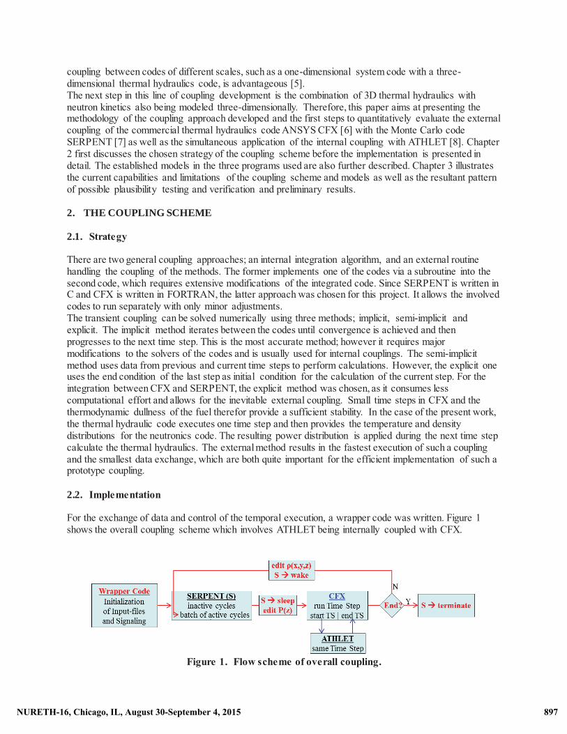
2.2. Implementation For the exchange of data and control of the temporal execution, a wrapper code was written. Figure 1 shows the overall coupling scheme which involves ATHLET being internally coupled with CFX.
Figure 1. Flow scheme of overall coupling.
897NURETH-16, Chicago, IL, August 30-September 4, 2015 897NURETH-16, Chicago, IL, August 30-September 4, 2015
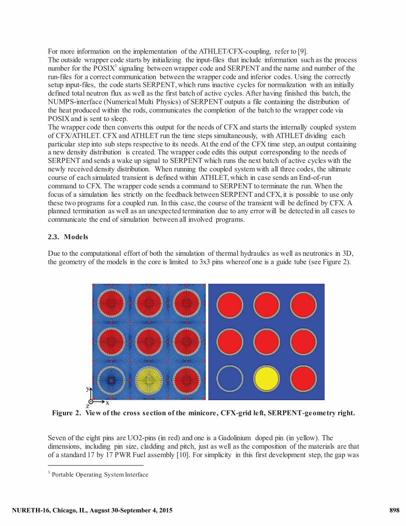
For more information on the implementation of the ATHLET/CFX-coupling, refer to [9]. The outside wrapper code starts by initializing the input-files that include information such as the process number for the POSIX1 signaling between wrapper code and SERPENT and the name and number of the run-files for a correct communication between the wrapper code and inferior codes. Using the correctly setup input-files, the code starts SERPENT, which runs inactive cycles for normalization with an initially defined total neutron flux as well as the first batch of active cycles. After having finished this batch, the NUMPS-interface (Numerical Multi Physics) of SERPENT outputs a file containing the distribution of the heat produced within the rods, communicates the completion of the batch to the wrapper code via POSIX and is sent to sleep. The wrapper code then converts this output for the needs of CFX and starts the internally coupled system of CFX/ATHLET. CFX and ATHLET run the time steps simultaneously, with ATHLET dividing each particular step into sub steps respective to its needs. At the end of the CFX time step, an output containing a new density distribution is created. The wrapper code edits this output corresponding to the needs of SERPENT and sends a wake up signal to SERPENT which runs the next batch of active cycles with the newly received density distribution. When running the coupled system with all three codes, the ultimate course of each simulated transient is defined within ATHLET, which in case sends an End-of-run command to CFX. The wrapper code sends a command to SERPENT to terminate the run. When the focus of a simulation lies strictly on the feedback between SERPENT and CFX, it is possible to use only these two programs for a coupled run. In this case, the course of the transient will be defined by CFX. A planned termination as well as an unexpected termination due to any error will be detected in all cases to communicate the end of simulation between all involved programs. 2.3. Models Due to the computational effort of both the simulation of thermal hydraulics as well as neutronics in 3D, the geometry of the models in the core is limited to 3x3 pins whereof one is a guide tube (see Figure 2).
Figure 2. View of the cross section of the minicore, CFX-grid left, SERPENT-geometry right.
Seven of the eight pins are UO2-pins (in red) and one is a Gadolinium doped pin (in yellow). The dimensions, including pin size, cladding and pitch, just as well as the composition of the materials are that of a standard 17 by 17 PWR Fuel assembly [10]. For simplicity in this first development step, the gap was 1 Portable Operating System Interface
898NURETH-16, Chicago, IL, August 30-September 4, 2015 898NURETH-16, Chicago, IL, August 30-September 4, 2015
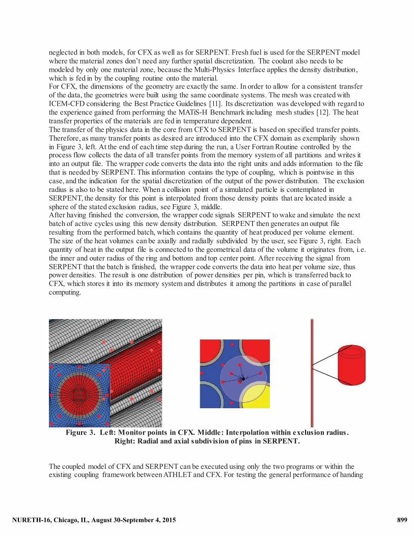
neglected in both models, for CFX as well as for SERPENT. Fresh fuel is used for the SERPENT model where the material zones don’t need any further spatial discretization. The coolant also needs to be modeled by only one material zone, because the Multi-Physics Interface applies the density distribution, which is fed in by the coupling routine onto the material. For CFX, the dimensions of the geometry are exactly the same. In order to allow for a consistent transfer of the data, the geometries were built using the same coordinate systems. The mesh was created with ICEM-CFD considering the Best Practice Guidelines [11]. Its discretization was developed with regard to the experience gained from performing the MATiS-H Benchmark including mesh studies [12]. The heat transfer properties of the materials are fed in temperature dependent. The transfer of the physics data in the core from CFX to SERPENT is based on specified transfer points. Therefore, as many transfer points as desired are introduced into the CFX domain as exemplarily shown in Figure 3, left. At the end of each time step during the run, a User Fortran Routine controlled by the process flow collects the data of all transfer points from the memory system of all partitions and writes it into an output file. The wrapper code converts the data into the right units and adds information to the file that is needed by SERPENT. This information contains the type of coupling, which is pointwise in this case, and the indication for the spatial discretization of the output of the power distribution. The exclusion radius is also to be stated here. When a collision point of a simulated particle is contemplated in SERPENT, the density for this point is interpolated from those density points that are located inside a sphere of the stated exclusion radius, see Figure 3, middle. After having finished the conversion, the wrapper code signals SERPENT to wake and simulate the next batch of active cycles using this new density distribution. SERPENT then generates an output file resulting from the performed batch, which contains the quantity of heat produced per volume element. The size of the heat volumes can be axially and radially subdivided by the user, see Figure 3, right. Each quantity of heat in the output file is connected to the geometrical data of the volume it originates from, i.e. the inner and outer radius of the ring and bottom and top center point. After receiving the signal from SERPENT that the batch is finished, the wrapper code converts the data into heat per volume size, thus power densities. The result is one distribution of power densities per pin, which is transferred back to CFX, which stores it into its memory system and distributes it among the partitions in case of parallel computing.
Figure 3. Left: Monitor points in CFX. Middle: Interpolation within exclusion radius .
Right: Radial and axial subdivision of pins in SERPENT. The coupled model of CFX and SERPENT can be executed using only the two programs or within the existing coupling framework between ATHLET and CFX. For testing the general performance of handing
899NURETH-16, Chicago, IL, August 30-September 4, 2015 899NURETH-16, Chicago, IL, August 30-September 4, 2015
over the data between the 3x3 pin geometry modeled in detail and the one-dimensional system code, a simplified lower and upper plenum has been connected to the CFX input and output. Figure 4 shows this setup, where the FILL can be seen as an Input parameter, which can be used to simulate simple thermal hydraulic changes in order to test the coupling between CFX and ATHLET. Furthermore, the layout is very well suited to connect SERPENT to the detailed core in order to determine the feedback between thermal hydraulics and neutronics by feeding different parameter quantities such as de- and increasing temperatures, densities or mass flows into the FILL zone.
Figure 4. Simple setup for testing of the CFX/ATHLET-coupling.
Figure 5 shows the layout to model a whole but simplified primary and secondary circuit with ATHLET. The primary loops are merged into one loop. The cold leg, including the main coolant pump, is connected to the next object representing the downcomer, leading in turn into the lower plenum. The last control volume of the lower plenum transfers its thermodynamic data such as temperature, flow velocity, enthalpy, pressure etc. to specific inlet variables of CFX, which is simulating the flow in the three dimensionally modeled minicore. At the outlet of the CFX core, the data is transferred back to ATHLET into the first control volume of the upper plenum and therefore back into the one dimensionally modeled primary circuit. The upper plenum is connected to the hot leg which is connected to a pressurizer. The hot leg again leads into the steam generator which is connected to a very simply modeled secondary circuit represented only as a heat sink. The internal coupling of the one-dimensional code with the three-dimensional code has been established in a semi-implicit manner by the GRS [5].
Figure 5. Model layout of the ATHLET part.
900NURETH-16, Chicago, IL, August 30-September 4, 2015 900NURETH-16, Chicago, IL, August 30-September 4, 2015
3. CURRENT CAPABILITIES AND TESTING Currently, delayed neutrons are not implemented in the Monte Carlo code SERPENT. This implies that it is only possible to run steady state simulations with a user-defined total number of cycles and number of particles per cycle. The recently developed version of this code which was used in the coupling, allows for the splitting of the cycles into batches and transferring the data for the coupling in between those cycles. When SERPENT is first started, the model is normalized to a fixed total neutron flux. For all following batches of active cycles, the fission source gets passed on from the previous batch. A dynamic mode for SERPENT is already under development [13] but as of yet is not suitable for the use together with the NUMPS coupling interface. This will be, together with an internal fuel temperature feedback mode, most likely available at the end of 2015 and will be implemented in the here presented coupling framework for further development. As mentioned above, the core is currently modeled in part by a simplified 3x3 pin geometry. With existing computing power, one could easily increase the represented part of the core as well as its complexity by introducing e.g. spacer geometries. With the objective of the project being the approach to a first concept of a coupled system, it was reasonable to limit the computational effort to get fast and easily reproducible and comparable results in a simplified geometry. The number of transfer points in CFX that are handed over to SERPENT have a slight influence on the computational time of SERPENT. But as long as the exclusion radius is adapted to the average distance between the density points, the number of density points to be considered for each collision point is constant and therefore the cost of interpolation is nearly constant. Again, due to runtime and the prototypic approach, a resolution has been chosen which is comparable to the level of using a subchannel code. This means that the model is currently running beyond the potential of high resolution codes, but is very well suitable for first fundamental feasibility studies. The missing fuel temperature feedback in the used SERPENT version allows investigating only slow thermal hydraulic transients which are limited to single phase flows in a first step of the assessment. The sum of the aforementioned capabilities and restrictions lead to the following set of simulated setups:
Table I. Test setups for coupled simulation
Programs ID Description
CFX ATHLET
1a
open system with lower and upper plenum in ATHLET connected to the detailed 3x3 core modeled in CFX testing the general feasibility of the coupling with simple thermal hydraulic transients introduced into the system via the FILL
1b
closed system with simplified primary and secondary circuit in ATHLET connected to the detailed 3x3 core modeled in CFX simulation of plant transients such as a small leak in the cold leg to compare the coupled results with ATHLET stand-alone
CFX ATHLET SERPENT
2a layout of 1.a with the core modeled by CFX coupled with SERPENT testing the feedback between thermal hydraulics and neutronics examination of the feasibility of the system to represent feedback coefficients
2b
layout of 1.b with the core modeled by CFX coupled with SERPENT running slow and gentle plant transients the introduction of point kinetics model in ATHLET allows the comparison of the coupled system with ATHLET stand-alone
901NURETH-16, Chicago, IL, August 30-September 4, 2015 901NURETH-16, Chicago, IL, August 30-September 4, 2015
4. RESULTS 4.1. Plausibility tests of the Coupled Model of CFX-SERPENT For the feedback between ANSYS CFX and SERPENT, different plausibility tests have been conducted. In a first steady test case, a constant density distribution of the coolant has been provided to SERPENT resulting in a symmetrical power distribution, which can be seen in Figure 6, left. The right diagram in Figure 6 shows the second case, where a real density distribution has been provided to SERPENT by CFX and leads to the known downshifted power distribution in the core.
Figure 6. Power distribution calculated by SERPENT – following constant and axially distributed
coolant density. Without a fuel temperature feedback available that can run together with the coupling interface and no delayed neutrons implemented yet in SERPENT, no dynamic behavior or feedback can be investigated thus far. But with the previously described version of SERPENT, which has the capability to run several batches with the intermediate storage of the initial normalization and fission source, it has recently become possible to consider moderator density feedback effects and assess the capabilities of the coupling framework in a transient scenario. A rise in the temperature of the coolant, and, respectively, a reduced density should lead to a decreased fission power due to reduced moderation of the neutrons. Figure 7 shows the comparison of the accumulated heating power in the rods. The curve resulting from coolant with a decreased density illustrates a reduced heating power as expected.
902NURETH-16, Chicago, IL, August 30-September 4, 2015 902NURETH-16, Chicago, IL, August 30-September 4, 2015
Figure 7. Influence of the coolant density on the accumulated heating power.
Even though the preliminary results from the feedback of the coupling of CFX with SERPENT are more qualitative thus far, a conservative and numerically stable data transfer and program coupling was demonstrated. Simulations to examine the quantitative influence to gain e.g. a moderator temperature coefficient are on-going. 4.2. Verification of the Coupled Model of CFX-SERPENT As a reference, DYN3D, a computer code that can feasibly perform steady-state and transient simulations with implemented modules for neutronics and thermal-hydraulics [14] was used in a code-to-code comparison to verify the results of the coupled program system. By means of this code, the above presented geometry was rebuilt to verify the newly developed coupling. The total heating power resulting from the CFX-SERPENT model was fed into the DYN3D model for normalization. DYN3D then calculated the deriving neutron kinetics and density and temperature distributions in the coolant. Figure 8 shows the comparison of the resulting axial power distribution averaged over all pins and the gradient of the coolant temperature averaged over the flow area for a steady-state simulation.
Figure 8. Comparison of Power Distribution and Coolant Temperature.
903NURETH-16, Chicago, IL, August 30-September 4, 2015 903NURETH-16, Chicago, IL, August 30-September 4, 2015
The power distributions are in very good agreement between both methods; the SERPENT distribution differs more due to the statistical way of calculating the neutron fluxes. The simulation first revealed a temperature difference at the outlet of about 6 Kelvin. Further discussion disclosed the different definition of thermodynamic properties that caused this deviation. Whereas constant heat capacities and heat transfer coefficients were used in DYN3D, CFX was equipped with temperature dependent properties. Another calculation with the CFX-SERPENT model using constant properties led to the shown gradient of the coolant temperature which is in closer accordance with the DYN3D solution. The remaining deviation is traced back to the different treatment of the heat transfer in both codes and will be further examined. 4.3. Results of the Coupled Model of CFX-ATHLET For the first testing of the thermal hydraulic coupling, a temperature ramp has been modeled with setup 1a (see Table I). The coupled layout with the core modeled by CFX using the 3x3 pin geometry was compared to a geometry completely modeled with the well-validated code ATHLET in stand-alone mode. To accomplish this, a setup of the core had to be developed in ATHLET as a so called TFO (thermo fluid object) with corresponding heat capacities, heat sources and friction losses.Figure 9 shows the course of the transferred temperature data. In the FILL, a temperature ramp of 2 K was introduced to rise within 2 seconds. It progresses through the lower plenum modeled by ATHLET and at the interface to the minicore modeled by CFX, the thermal hydraulic quantities from the last node in ATHLET are transferred as boundary conditions to the 3D-code. The temperature rise continues through the CFX volume and at the outlet, spatially averaged values are given back to ATHLET. Due to the coarse manner of storing the transfer values by the interface, they appear as step functions. The values at the inlet show very good agreement as expected. The outlet on the other hand shows a slight deviation in the evolution of the transient due to differences in the heat transfer representation and then matches again at the end of the ramp.
Figure 9. Simple test case to investigate the correct behavior of the coupling of CFX and ATHLET. Subsequently, a transient arising in the primary circuit was simulated and compared between stand-alone and the coupled code system with setup 1b (see Table I). In this case, a leak occurs in the cold leg at 10
904NURETH-16, Chicago, IL, August 30-September 4, 2015 904NURETH-16, Chicago, IL, August 30-September 4, 2015
seconds with an initial mass flow rate of 25 kg/s (Figure 10, left). Hereupon the control model of ATHLET initiates SCRAM and the main coolant pump coasts down. As a result, depressurization is initiated and the core pressure drops continuously, which leads to the pressure curve in the lower plenum (see Figure 10, right).
Figure 10. Mass flow rate of the leak and pressure in the upper plenum following depressurization. Figure 11 shows the resulting temperature trend in the upper core during this transient. The heat production in the core follows the well-known Way-Wigner approximation equation of decay heat [15], which is included in both models as a time-dependent heat source, starting to decrease simultaneously with the SCRAM at t=10 s simulation time.
Figure 11. Temperature trend in the upper core during a transient with a small leak coupled and stand-alone simulation.
905NURETH-16, Chicago, IL, August 30-September 4, 2015 905NURETH-16, Chicago, IL, August 30-September 4, 2015
The leak first provokes a rise of the temperature in the core. Following SCRAM with a fast reducing decay heat and depressurization procedures, it slowly decreases again. Due to the different approach of modeling the heat transfer in ATHLET and CFX, it was expected that the curves would not be perfectly identical. However, the coupled 1D-3D thermal hydraulics system shows the expected consistency with the stand-alone simulation of ATHLET for all compared quantities in different positions of the geometry and global balances. A verification of the coupled system utilizing all three codes is currently ongoing by means of ATHLET including its point kinetics module. This will allow a comparison and further evaluation of the current range of functionality of the coupling between all three codes. 5. CONCLUSIONS The current paper presented a newly developed coupling scheme between the three-dimensional thermal hydraulic code ANSYS CFX with the three-dimensional Monte Carlo code SERPENT which is implemented to be executed within the framework of CFX coupling with the one-dimensional system code ATHLET. The first results are encouraging and demonstrate the consistent and numerically robust data handling. A preliminary qualitative assessment of moderator feedback is reasonable and in good agreement with a DYN3D model. The next step will be the realization of the chosen test case with the three-code-system in order to compare the results with those from ATHLET in stand-alone mode to not only show the plausibility of the system, but to also verify the feedback between all three codes. Besides the validation, additional improvements to be included into the system will be added. The pointwise coupling of ANSYS CFX with SERPENT with interpolating between the transfer points is planned to be further developed into a method where SERPENT will get the mesh based information. Another enhancement of the model might be the introduction of spacer grids in the CFX geometry in order to benefit from this new coupling approach. The development is performed in parallel to the enhancement of SERPENT and its NUMPS interface by VTT and will continuously include enhancements. REFERENCES 1. W. Bernnat, “Coupled neutronics and thermal hydraulics analysis for PWR with MCNP5 and
ATHLET”, Proceedings of 42nd Annual Meeting on Nuclear Technology, Berlin, Germany, May 17-19, 2011.
2. S. Langenbuch et al., “Development of coupled systems of 3D neutronics and fluid - dynamic system codes and their application for safety analysis”, Eurosafe 2000, Cologne, Germany, November 6-7, 2000.
3. D’Auria et al., Neutronics/thermal-hydraulics coupling in LWR technology, vol. 1. Technical report, OECD/NEA, 2004.
4. B. Sjenitzer, “Coupling of dynamic Monte Carlo with thermal-hydraulic feedback”, Annals of Nuclear Energy, 76, pp. 27-39 (2015).
5. A. Papukchiev, “Development of a Coupling Methodology for the System Code ATHLET and the Advanced 3D CFD Tool ANSYS CFX”, Proceedings of 41st Annual Meeting on Nuclear Technology, Berlin, Germany, May 4-6, 2010.
6. ANSYS CFX Solver Theory Guide, ANSYS, Inc., Southpointe, November 2013. 7. J. Leppänen, “PSG2 / Serpent – a Continuous-energy Monte Carlo Reactor Physics Burnup
Calculation Code”, User’s Manual, VTT Technical Research Centre of Finland, June 13, 2012. 8. G. Lerchl, H. Austregesilo, ATHLET Mod 3.0 Cycle A, User's Manual, November 2012, GRS P 1/
Vol. 1 Rev. 6. 9. A. Papukchiev, “Coupling of ANSYS CFX and ATHLET: Progress Report”, Presentation at the 16th
meeting of German CFD Network, Garching, Germany, October 7-8, 2009.
906NURETH-16, Chicago, IL, August 30-September 4, 2015 906NURETH-16, Chicago, IL, August 30-September 4, 2015
10. B. Roque et al., "Specification for the Phase 1 of a Depletion Calculation Benchmark devoted to Fuel Cycles", NEA/NSC/DOC(2004)11, OECD/NEA (2004).
11. F. Menter et al., “CFD Best Practice Guidelines for CFD Code Validation for Reactor-Safety Applications,” European Commission, 5th EURATOM Framework Programme, Report, EVOL-ECORA-D1, 2002.
12. B. L. Smith et al., Report of the OECD/NEA KAERI Rod Bundle CFD Benchmark, NEA/CSNI/R(2013)5, OECD/NEA (2013).
13. J. Leppänen, “Development of a Dynamic Simulation Mode in the SERPENT 2 Monte Carlo Code”, Proceedings of M&C 2013, Sun Valley, Idaho, May 5-9, 2013.
14. U. Grundmann, "The Code DYN3DR for Steady-State and Transient Analyses of Light Water Reactor Cores with Cartesian Geometry," Report FZR-114, Rossendorf, November 1995.
15. K. Way, E.P. Wigner, “The Rate of Decay of Fission Products”, Physical Review 70, pp. 1318-1330 (1946).
907NURETH-16, Chicago, IL, August 30-September 4, 2015 907NURETH-16, Chicago, IL, August 30-September 4, 2015