Proceedings World Geothermal Congress 2010 Bali, Indonesia, 25-29 April 2010 1 Towards an Integrated Simulator for Enhanced Geothermal Reservoirs H. L. Xing*, J. Gao, J. Zhang and Y. Liu The University of Queensland, Earth System Science Computational Centre, St Lucia, QLD 4072, Australia * Corresponding author: [email protected]Keywords: Integrated reservoir simulation, High performance computing, Finite element method, Lattice Boltzmann method, Microseismicity, Permeability, Enhanced geothermal reservoirs ABSTRACT This paper introduces the current state in computer modelling of geothermal reservoir system and then focuses on our research efforts in high performance simulation of enhanced geothermal reservoir system. PANDAS - Parallel Adaptive static/dynamic Nonlinear Deformation Analysis System - a novel supercomputer simulation tool has been developing for simulating the highly non-linear coupled geomechanical-fluid flow-thermal systems involving heterogeneously fractured geomaterials at different spatial and temporal scales. It is applied to simulate and visualise the enhanced geothermal system (EGS), such as (1) visualisation of the microseismic events to monitor and determine where/how the underground rupture proceeds during a hydraulic stimulation, to generate the mesh using the recorded data for determining the domain of the ruptured zone and to evaluate the material parameters (i.e. the permeability) for the further numerical analysis; (2) converting the available fractured rock image/fracture data to lattice grid and further simulating the fluid flow in the complicated fractures involving the detailed description of fracture dimension and geometry by the Lattice Boltzmann method; (3) interacting fault system simulation to determine the relevant complicated dynamic rupture process; (4) multiphase coupled thermo-fluid flow analysis of a geothermal reservoir system. A few of benchmark and application examples are presented to show its accuracy, stability and usefulness in simulating the enhanced geothermal reservoir system. 1. INTRODUCTION A large amount of research and testing on EGS, such as HDR (hot dry rock), HFR (hot fractured rock) and HWR (hot wet rock) geothermal reservoirs, has been accomplished worldwide in the past 30 years including reservoir construction, fluid circulation and heat extraction. A successful EGS reservoir depends on thermal-fluid flow at any given time. This is primarily determined by (e.g. Brown et al., 1999): (1) the nature of the interconnected network of hydraulic stimulated joints and open fractures (including both stimulated and natural) within the flow- accessible reservoir region; (2) the mean temperature and pressure in the reservoir; (3) the cumulative amount of fluid circulation (reservoir cooling) that has occurred; and (4) water loss. In order to understand, model and predict the thermal power performance of an EGS reservoir, it is necessary to have good measures and understanding of the following two interrelated reservoir properties: (a) the effective heat transfer volume at high temperature; and (b) the fracture/joints and its distribution within the effective heat transfer volume. Both highly affects the reservoir characteristics (i.e. permeability), which are complicated and are functions of the applied reservoir pressure/stress that are controlling the nature and degree of interconnection within the network of fractures. A further literature survey (e.g. Bjornsson and Bodvarsson, 1990) on thermal, hydrological and chemical characteristics of geothermal reservoirs and their relevant parameters - permeability, permeability-thickness, porosity, reservoir temperature and concentration of dissolved solids and non-condensable gases – suggests that reservoir permeability, porosity and total dissolved solids tend to be a function of temperature. All the above demonstrates that an EGS is a complicated Thermal-Hydro-Mechanical-Chemical (THMC) coupled system, which requires more comprehensive understanding and modelling of coupled processes than that commonly done in standard reservoir engineering. Recent studies on computer modelling the conventional geothermal reservoir engineering and the EGS/HDR system are reviewed by O’Sullivan et al. (2001) and Sanyal et al. (2000) respectively. They showed that computer modelling is routinely applied in conventional hydrothermal reservoir engineering, but it is comparatively immature in EGS. Based on the above and other recent studies, existing EGS simulators are faced with following challenges: (1). Geomechanical deformation/rock stress and its full coupling with the multiphase thermal-fluid flow and chemicals are not addressed yet. Such coupled models are critical for analysing the geothermal reservoir system especially for EGS. Further research is needed in exploring different approximations for coupled processes with vastly different intrinsic spatial and temporal scales. Such a coupled treatment can potentially provide a more realistic description of geothermal reservoir processes during natural/stimulated evolution as well as during exploitation. It can also provide added constraints that can help reduce the inherent uncertainty of geothermal reservoir models. (2). A reliable fully-coupled treatment of 3D fluid flow and mass transport with detailed chemical interactions between aqueous fluids, gases, and primary mineral assemblages still requires further research. This may be currently available in hydrothermal code TOUGH2, but not available in the other codes including all the HDR simulators/FEM simulators. (3). The relevant reservoir model generation and meshing are still difficult and time consuming especially for fracture dominated EGS. The finite difference method is widely used in geothermal modelling but requires regular rectangular mesh structure. The popular geothermal code TOUGH2 may handle irregular meshes theoretically, but most of models set up using TOUGH2 contain some structure, such as layering. It is impossible to explicitly describe the complicated fractures in an EGS reservoir with such mesh structures. Unstructured mesh may be a better choice, but no unstructured mesh based solver - finite element solver - as powerful as such as TOUGH2 is available for geothermal simulation yet.
Transcript
Proceedings World Geothermal Congress 2010 Bali, Indonesia, 25-29 April 2010
1
Towards an Integrated Simulator for Enhanced Geothermal Reservoirs
H. L. Xing*, J. Gao, J. Zhang and Y. Liu
The University of Queensland, Earth System Science Computational Centre, St Lucia, QLD 4072, Australia
Keywords: Integrated reservoir simulation, High performance computing, Finite element method, Lattice Boltzmann method, Microseismicity, Permeability, Enhanced geothermal reservoirs
ABSTRACT
This paper introduces the current state in computer modelling of geothermal reservoir system and then focuses on our research efforts in high performance simulation of enhanced geothermal reservoir system. PANDAS - Parallel Adaptive static/dynamic Nonlinear Deformation Analysis System - a novel supercomputer simulation tool has been developing for simulating the highly non-linear coupled geomechanical-fluid flow-thermal systems involving heterogeneously fractured geomaterials at different spatial and temporal scales. It is applied to simulate and visualise the enhanced geothermal system (EGS), such as (1) visualisation of the microseismic events to monitor and determine where/how the underground rupture proceeds during a hydraulic stimulation, to generate the mesh using the recorded data for determining the domain of the ruptured zone and to evaluate the material parameters (i.e. the permeability) for the further numerical analysis; (2) converting the available fractured rock image/fracture data to lattice grid and further simulating the fluid flow in the complicated fractures involving the detailed description of fracture dimension and geometry by the Lattice Boltzmann method; (3) interacting fault system simulation to determine the relevant complicated dynamic rupture process; (4) multiphase coupled thermo-fluid flow analysis of a geothermal reservoir system. A few of benchmark and application examples are presented to show its accuracy, stability and usefulness in simulating the enhanced geothermal reservoir system.
1. INTRODUCTION
A large amount of research and testing on EGS, such as HDR (hot dry rock), HFR (hot fractured rock) and HWR (hot wet rock) geothermal reservoirs, has been accomplished worldwide in the past 30 years including reservoir construction, fluid circulation and heat extraction. A successful EGS reservoir depends on thermal-fluid flow at any given time. This is primarily determined by (e.g. Brown et al., 1999): (1) the nature of the interconnected network of hydraulic stimulated joints and open fractures (including both stimulated and natural) within the flow-accessible reservoir region; (2) the mean temperature and pressure in the reservoir; (3) the cumulative amount of fluid circulation (reservoir cooling) that has occurred; and (4) water loss. In order to understand, model and predict the thermal power performance of an EGS reservoir, it is necessary to have good measures and understanding of the following two interrelated reservoir properties: (a) the effective heat transfer volume at high temperature; and (b) the fracture/joints and its distribution within the effective heat transfer volume. Both highly affects the reservoir characteristics (i.e. permeability), which are complicated
and are functions of the applied reservoir pressure/stress that are controlling the nature and degree of interconnection within the network of fractures. A further literature survey (e.g. Bjornsson and Bodvarsson, 1990) on thermal, hydrological and chemical characteristics of geothermal reservoirs and their relevant parameters - permeability, permeability-thickness, porosity, reservoir temperature and concentration of dissolved solids and non-condensable gases – suggests that reservoir permeability, porosity and total dissolved solids tend to be a function of temperature. All the above demonstrates that an EGS is a complicated Thermal-Hydro-Mechanical-Chemical (THMC) coupled system, which requires more comprehensive understanding and modelling of coupled processes than that commonly done in standard reservoir engineering.
Recent studies on computer modelling the conventional geothermal reservoir engineering and the EGS/HDR system are reviewed by O’Sullivan et al. (2001) and Sanyal et al. (2000) respectively. They showed that computer modelling is routinely applied in conventional hydrothermal reservoir engineering, but it is comparatively immature in EGS. Based on the above and other recent studies, existing EGS simulators are faced with following challenges:
(1). Geomechanical deformation/rock stress and its full coupling with the multiphase thermal-fluid flow and chemicals are not addressed yet. Such coupled models are critical for analysing the geothermal reservoir system especially for EGS. Further research is needed in exploring different approximations for coupled processes with vastly different intrinsic spatial and temporal scales. Such a coupled treatment can potentially provide a more realistic description of geothermal reservoir processes during natural/stimulated evolution as well as during exploitation. It can also provide added constraints that can help reduce the inherent uncertainty of geothermal reservoir models.
(2). A reliable fully-coupled treatment of 3D fluid flow and mass transport with detailed chemical interactions between aqueous fluids, gases, and primary mineral assemblages still requires further research. This may be currently available in hydrothermal code TOUGH2, but not available in the other codes including all the HDR simulators/FEM simulators.
(3). The relevant reservoir model generation and meshing are still difficult and time consuming especially for fracture dominated EGS. The finite difference method is widely used in geothermal modelling but requires regular rectangular mesh structure. The popular geothermal code TOUGH2 may handle irregular meshes theoretically, but most of models set up using TOUGH2 contain some structure, such as layering. It is impossible to explicitly describe the complicated fractures in an EGS reservoir with such mesh structures. Unstructured mesh may be a better choice, but no unstructured mesh based solver - finite element solver - as powerful as such as TOUGH2 is available for geothermal simulation yet.
Xing et al.
2
(4). No module for visualizing microseismicity and evaluating the relevant rupture and permeability distribution for the further simulation has been integrated into such as the finite element based simulator so far.
(5). No module for automatic converting the complicated fractures to computational model and further calculating the fluid flow in such complicated fractures considering the detailed fracture size and geometry in an explicit way in geothermal community yet, despite such a computational algorithm (i.e. Lattice Boltzmann method) already used in other scientific fields.
(6). No multiscale computing or parallel computing involved in the widely available geothermal simulators yet despite their well-studied and widespread application in other fields.
In conclusion, further computational model and code developments are urgently needed to improve our understanding of geothermal reservoir and the relevant natural and/or enhanced evolution such as of enhanced geothermal reservoir system, and achieve a more accurate and comprehensive representation of reservoir processes in more details, to reduce the uncertainties in models, and to enhance the practical utility and reliability of reservoir simulation as a basis for field development and management (e.g. O’Sullivan et al., 2001, Sanyal et al., 2000). This paper will focus on our research efforts towards an integrated high performance simulation of enhanced geothermal reservoir systems.
2. AN INTEGRATED GEOTHERMAL RESERVOIR SIMULATOR
Australia has a unique Hot Fractured Rock geothermal resource that could potentially provide enough Green energy to meet all its energy needs. A novel finite element and/or Lattice Boltzmann method based supercomputer simulation tool has been developing for simulating the highly coupled geomechanical-fluid flow-thermal systems involving heterogeneously fractured geomaterials towards address the key scientific and technological challenge in developing EGS energy. Currently, it includes the following six key components: Pandas/Pre, ESyS_Crustal, Pandas/Thermo, Pandas/Fluid, Pandas/LBM and Pandas/Post as detailed in the following (Xing and Makinouchi, 2002; Xing et al 2006a, 2006b, 2007 and 2008; Xu et al 2007):
• Pandas/Pre is developed to visualise the microseismicity events recorded during the hydraulic stimulation process and to further evaluate the fracture location and evolution, geological setting, volume of fractured domain and the relevant material parameters (i.e. permeability) of a certain reservoir, and then to generate the mesh by it and/or other commercial graphics software (such as Patran) for the further finite element/Lattice Boltzmann analysis of various cases. The Delaunay algorithm is applied as a suitable method for mesh generation using such a point set.
• ESyS_Crustal is a finite element method based module developed for the interacting fault system simulation. It employs the adaptive static/dynamic algorithm to simulate the dynamics and evolution of interacting fault systems and processes, in which several dynamic phenomena related with stick-slip instability along the faults need to be taken into account, i.e. (a). slow quasi-static stress accumulation, (b) rapid dynamic rupture, (c) wave propagation and
(d) corresponding stress redistribution due to the energy release along the multiple fault boundaries. All these are needed to better describe ruputure/microseimicity/earthquake related phenomena with applications in earthquake forecasting, reservoir engineering, hazard quantification, exploration, and environmental problems. It has been verified and applied in different cases (e.g. see Xing 2007 and references thereafter).
• Pandas/Thermo is a finite element method based module for the thermal analysis of the metals and the fractured porous media; the temperature distribution is calculated from the heat transfer induced by the thermal boundary conditions without/with the coupled fluid flow effects in the fractured porous media and the geomechanical energy conversion for the individual/coupled thermal analysis.
• Pandas/Fluid is a finite element method based module for simulating the fluid flow in the fractured porous media by solving the conservation equations of macroscopic properties numerically. Here the fluid flow velocity and pressure are calculated from energy equilibrium equations without/with the coupling effects of the thermal and solid rock deformation for the individual/coupled fluid flow analysis.
• Pandas/LBM is a Lattice Boltzmann method (LBM) based module newly developed for explicitly simulating the 2D/3D complicated fluid flow in the complicated fractures involving the detailed fracture size and geometry. Instead of solving the conventional Navier–Stokes equations or its simplified form with macroscopic properties, the discrete Boltzmann equation is solved here to simulate the fluid flow with collision models such as Bhatnagar-Gross-Krook (BGK). LBM models the fluid consisting of fictive particles, and such particles perform consecutive propagation and collision processes over a discrete lattice mesh. By simulating streaming and collision processes across a limited number of particles, the intrinsic particle interactions evince a microcosm of viscous flow behaviour applicable across the greater mass (e.g. Sukop and Thorne, 2007). Due to its particulate nature and local dynamics, LBM has several advantages over other conventional CFD methods, especially in dealing with complex boundaries such as multiphase fluid flow in complicated fractures/porous media with detailed microstructures, incorporating microscopic interactions, and parallelization of the algorithm.
• Pandas/Post is to visualise the simulation results through the integration of VTK and/or Patran.
All the above modules can be used independently/together to simulate individual/coupled phenomena (such as interacting fault system dynamics, heat flow and fluid flow) without/with coupling effects.
3. APPLICATION EXAMPLES
PANDAS has been applied to various cases including those in geothermal reservoir systems. Three of them are listed as below.
3.1 Fluid Flow in Fractured Media
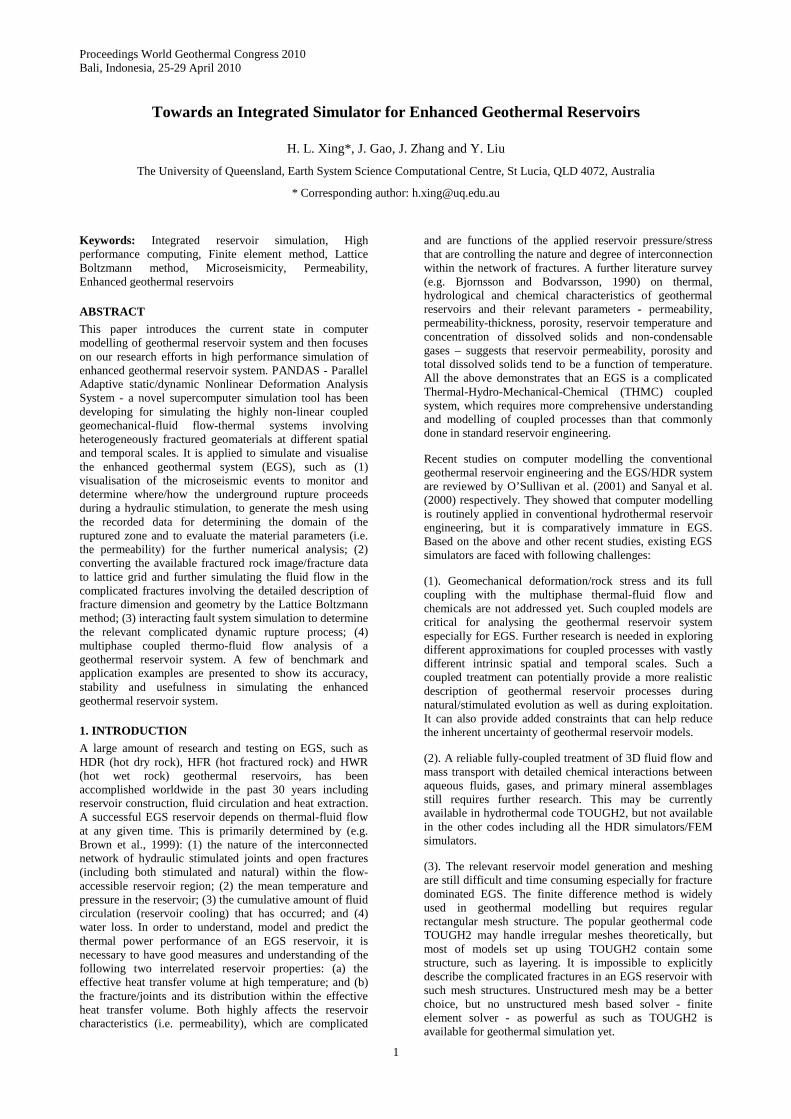
Pandas/LBM is applied here to simulate the fluid flow in fractured media. Figure 1 shows the fractured rock image
Xing et al.
3
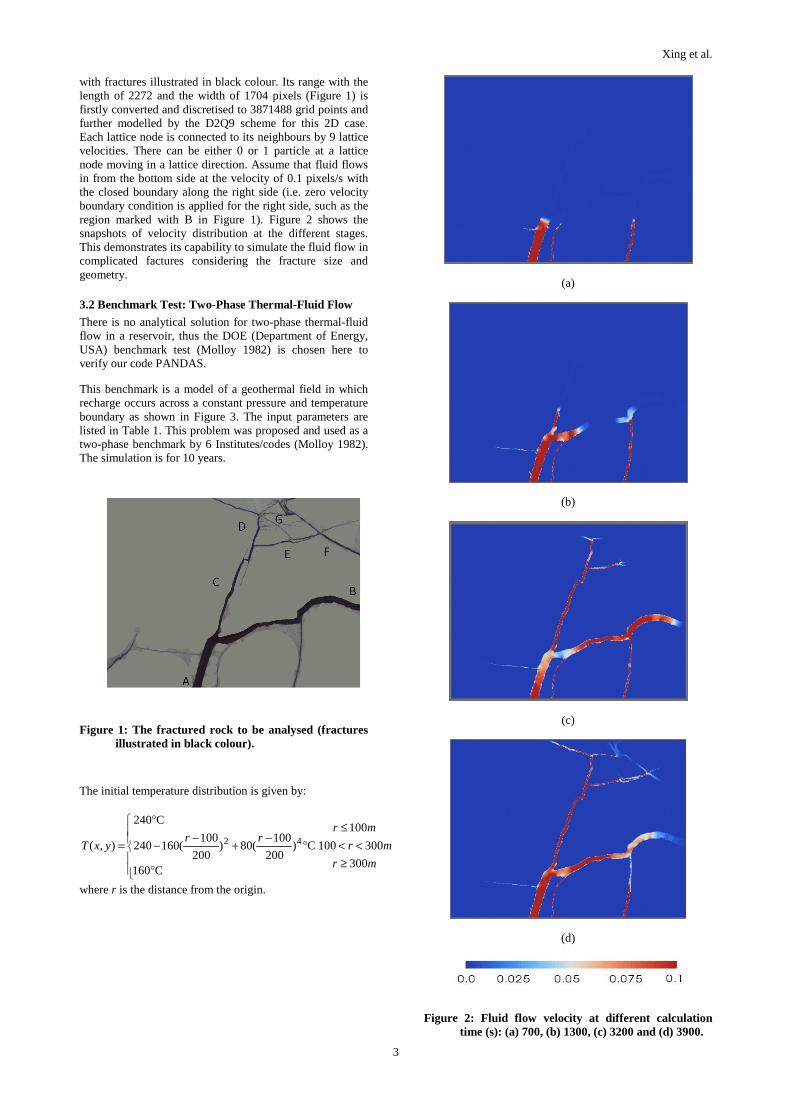
with fractures illustrated in black colour. Its range with the length of 2272 and the width of 1704 pixels (Figure 1) is firstly converted and discretised to 3871488 grid points and further modelled by the D2Q9 scheme for this 2D case. Each lattice node is connected to its neighbours by 9 lattice velocities. There can be either 0 or 1 particle at a lattice node moving in a lattice direction. Assume that fluid flows in from the bottom side at the velocity of 0.1 pixels/s with the closed boundary along the right side (i.e. zero velocity boundary condition is applied for the right side, such as the region marked with B in Figure 1). Figure 2 shows the snapshots of velocity distribution at the different stages. This demonstrates its capability to simulate the fluid flow in complicated factures considering the fracture size and geometry.
3.2 Benchmark Test: Two-Phase Thermal-Fluid Flow
There is no analytical solution for two-phase thermal-fluid flow in a reservoir, thus the DOE (Department of Energy, USA) benchmark test (Molloy 1982) is chosen here to verify our code PANDAS.
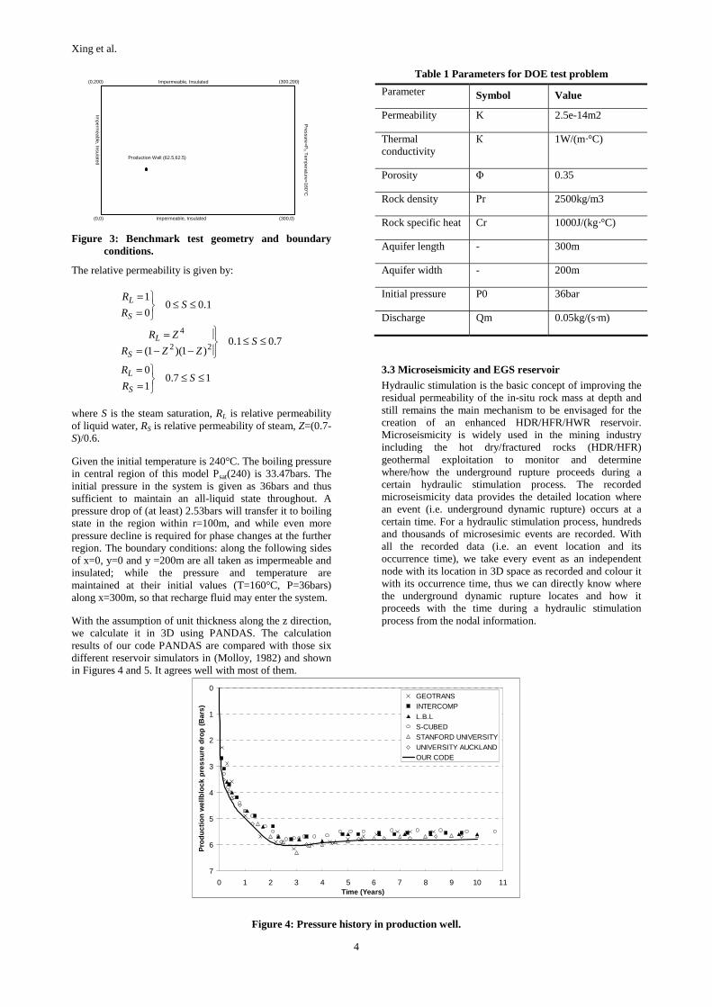
This benchmark is a model of a geothermal field in which recharge occurs across a constant pressure and temperature boundary as shown in Figure 3. The input parameters are listed in Table 1. This problem was proposed and used as a two-phase benchmark by 6 Institutes/codes (Molloy 1982). The simulation is for 10 years.
Figure 1: The fractured rock to be analysed (fractures illustrated in black colour).
The initial temperature distribution is given by:
mr
mr
mrrr
yxT
300
300100
100
C160
C)200
100(80)
200
100(160240
C240
),( 42
≥<<
≤
⎪⎪⎩
⎪⎪⎨
⎧
°
°−
+−
−
°
=
where r is the distance from the origin.
(a)
(b)
(c)
(d)
Figure 2: Fluid flow velocity at different calculation time (s): (a) 700, (b) 1300, (c) 3200 and (d) 3900.
Xing et al.
4
Figure 3: Benchmark test geometry and boundary conditions.
The relative permeability is given by:
17.01
0
7.01.0)1)(1(
1.000
1
22
4
≤≤⎭⎬⎫
==
≤≤⎪⎭
⎪⎬⎫
−−==
≤≤⎭⎬⎫
==
SR
R
SZZR
ZR
SR
R
S
L
S
L
S
L
where S is the steam saturation, RL is relative permeability of liquid water, RS is relative permeability of steam, Z=(0.7-S)/0.6.
Given the initial temperature is 240°C. The boiling pressure in central region of this model Psat(240) is 33.47bars. The initial pressure in the system is given as 36bars and thus sufficient to maintain an all-liquid state throughout. A pressure drop of (at least) 2.53bars will transfer it to boiling state in the region within r=100m, and while even more pressure decline is required for phase changes at the further region. The boundary conditions: along the following sides of x=0, y=0 and y =200m are all taken as impermeable and insulated; while the pressure and temperature are maintained at their initial values (T=160°C, P=36bars) along x=300m, so that recharge fluid may enter the system.
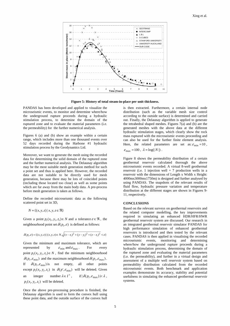
With the assumption of unit thickness along the z direction, we calculate it in 3D using PANDAS. The calculation results of our code PANDAS are compared with those six different reservoir simulators in (Molloy, 1982) and shown in Figures 4 and 5. It agrees well with most of them.
Table 1 Parameters for DOE test problem
Parameter Symbol Value
Permeability K 2.5e-14m2
Thermal conductivity
К 1W/(m·°C)
Porosity Φ 0.35
Rock density Ρr 2500kg/m3
Rock specific heat Cr 1000J/(kg·°C)
Aquifer length - 300m
Aquifer width - 200m
Initial pressure P0 36bar
Discharge Qm 0.05kg/(s·m)
3.3 Microseismicity and EGS reservoir
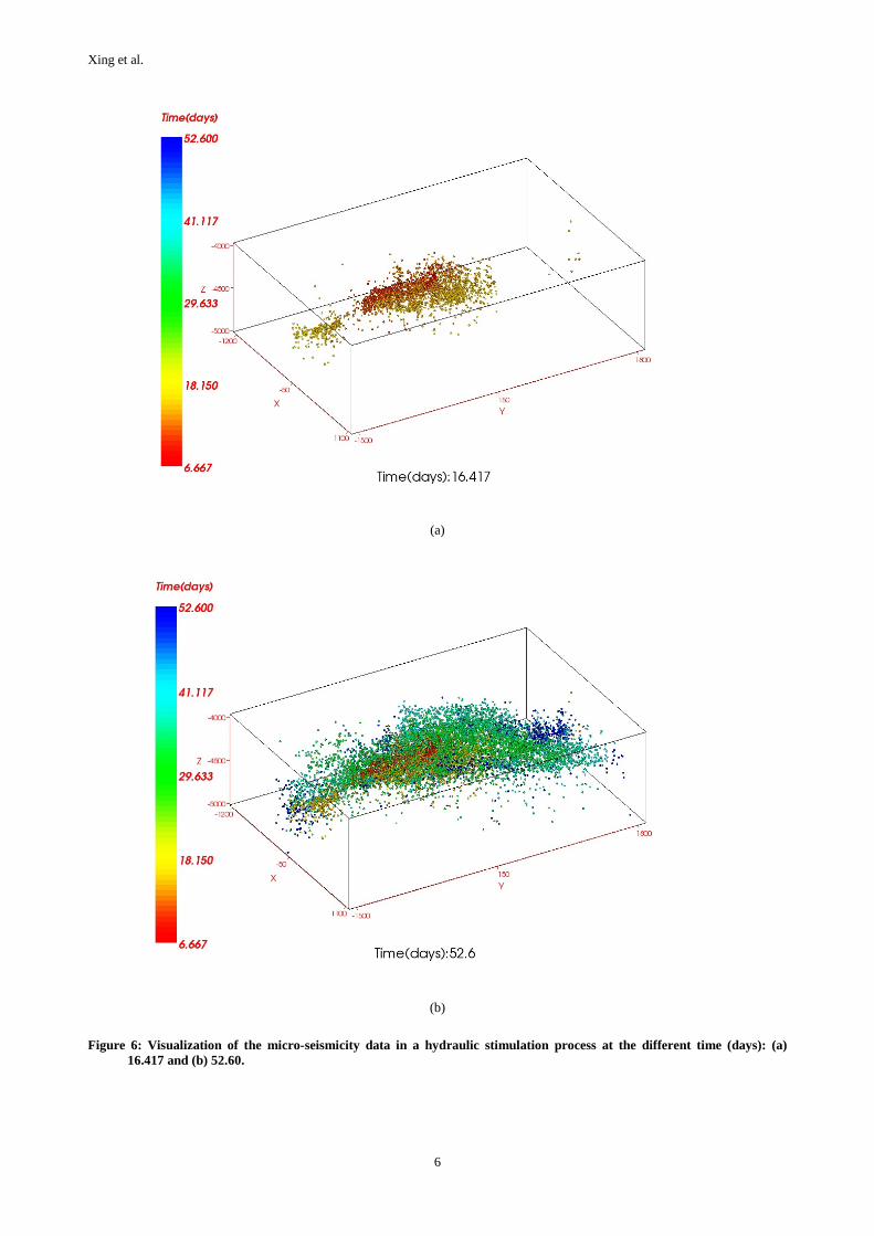
Hydraulic stimulation is the basic concept of improving the residual permeability of the in-situ rock mass at depth and still remains the main mechanism to be envisaged for the creation of an enhanced HDR/HFR/HWR reservoir. Microseismicity is widely used in the mining industry including the hot dry/fractured rocks (HDR/HFR) geothermal exploitation to monitor and determine where/how the underground rupture proceeds during a certain hydraulic stimulation process. The recorded microseismicity data provides the detailed location where an event (i.e. underground dynamic rupture) occurs at a certain time. For a hydraulic stimulation process, hundreds and thousands of microsesimic events are recorded. With all the recorded data (i.e. an event location and its occurrence time), we take every event as an independent node with its location in 3D space as recorded and colour it with its occurrence time, thus we can directly know where the underground dynamic rupture locates and how it proceeds with the time during a hydraulic stimulation process from the nodal information.
Figure 5: History of total steam-in-place per unit thickness.
PANDAS has been developed and applied to visualize the microseismic events, to monitor and determine where/how the underground rupture proceeds during a hydraulic stimulation process, to determine the domain of the ruptured zone and to evaluate the material parameters (i.e. the permeability) for the further numerical analysis.
Figures 6 (a) and (b) show an example within a certain range, which includes more than one thousand events over 52 days recorded during the Harbone #1 hydraulic stimulation process by the Geodynamics Ltd.
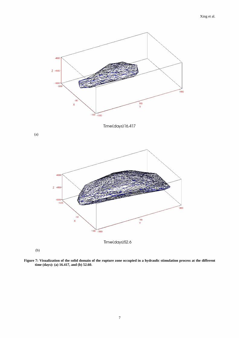
Moreover, we want to generate the mesh using the recorded data for determining the solid domain of the ruptured zone and the further numerical analysis. The Delaunay algorithm may be the most suitable mesh generation method for such a point set and thus is applied here. However, the recorded data are not suitable to be directly used for mesh generation, because there may be lots of coincided points (including those located too close) as well as some points which are far away from the main body data. A pre-process before mesh generation is taken as follows.
Define the recorded microseismic data as the following scattered point set in 3D,
},,|),,{( ℜ∈= zyxzyxN
Given a point Nzyxp iiii ∈),,( and a tolerance ℜ∈ε , the
neighbourhood point set ),( εδ ip is defined as follows:
Given the minimum and maximum tolerance, which are represented by minε and maxε . For every
point Nzyxp iiii ∈),,( , find the minimum neighbourhood
),( minεδ ip and the maximum neighbourhood ),( maxεδ ip .
If ),( minεδ ip is not empty, all other points
except ),,( iiii zyxp in ),'( minεδ p will be deleted. Given
an integer number +∈ Iλ , if λεδ <|),(| maxip ,
),,( iiii zyxp will be deleted.
Once the above pre-processing procedure is finished, the Delaunay algorithm is used to form the convex hull using these point data, and the outside surface of the convex hull
is then extracted. Furthermore, a certain internal node distribution (such as the variable mesh size control according to the outside surface) is determined and carried out. Finally, the Delaunay algorithm is applied to generate the tetrahedral shaped meshes. Figures 7(a) and (b) are the generated meshes with the above data at the different hydraulic stimulation stages, which clearly show the rock mass ruptured with the microseismic events proceeding and can also be used for the further finite element analysis. Here, the related parameters are set as: 10min =ε ,
100max =ε , |)log(| N=λ .
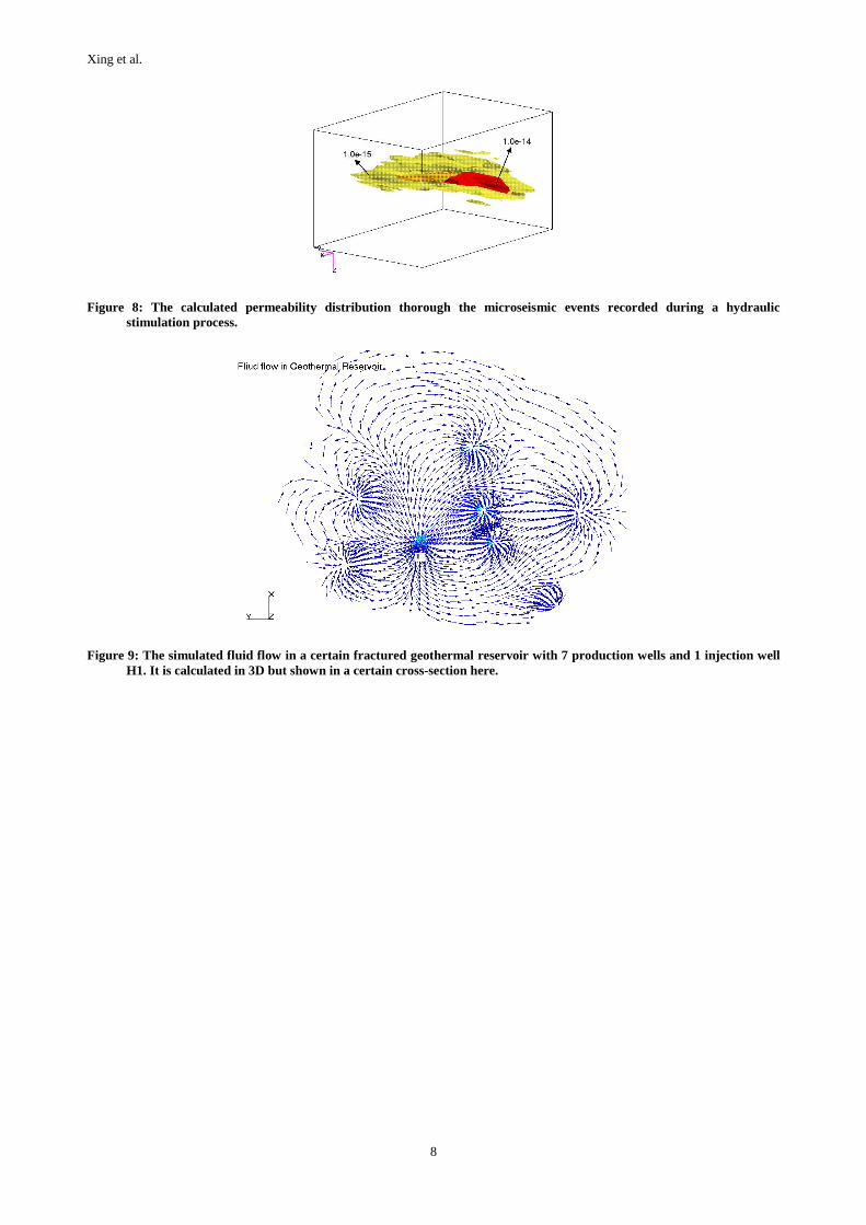
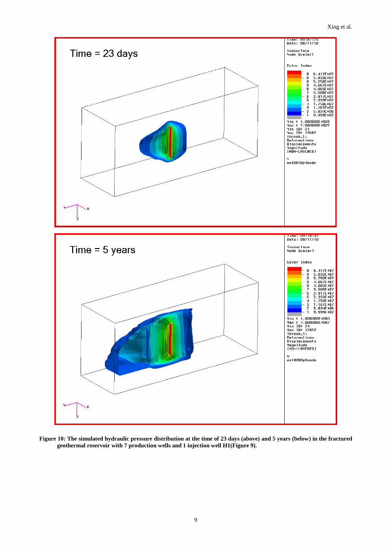
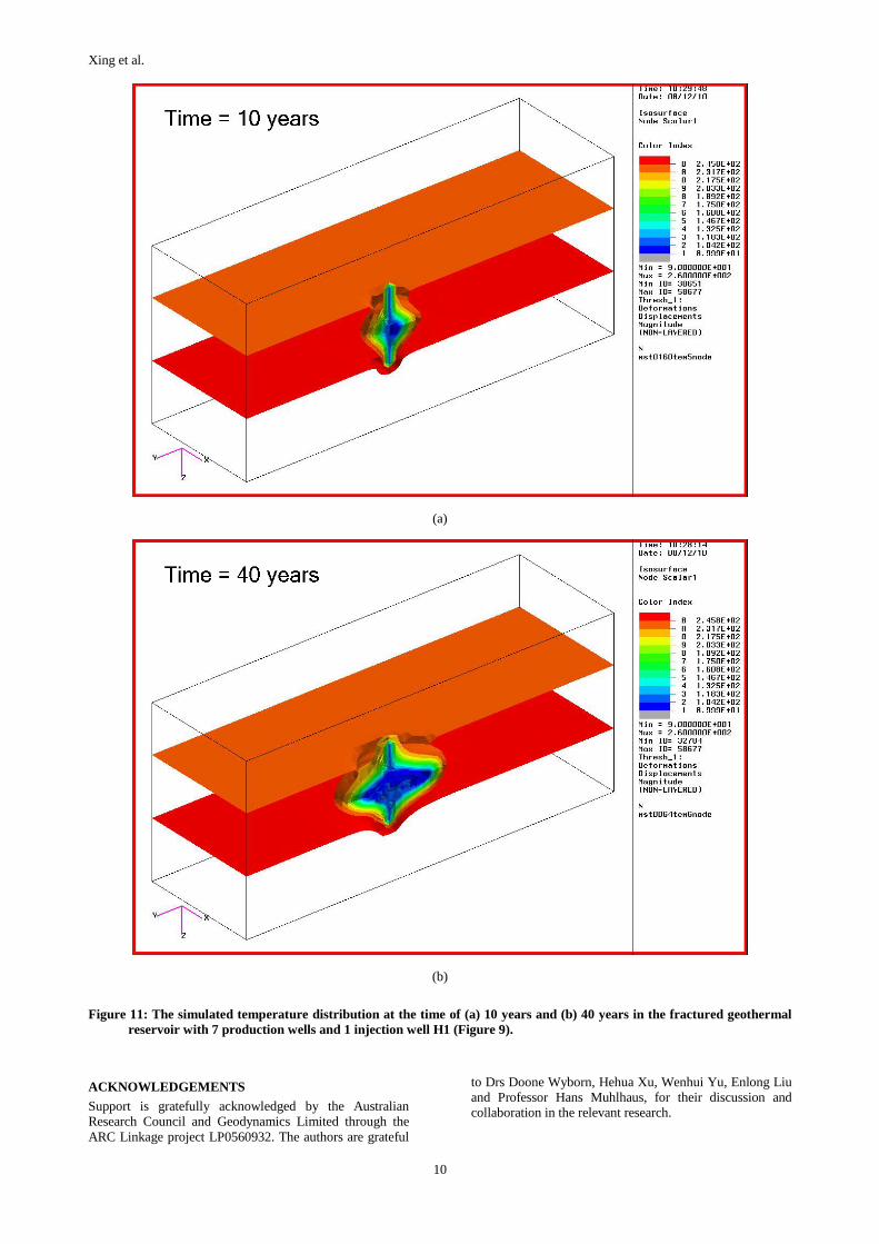
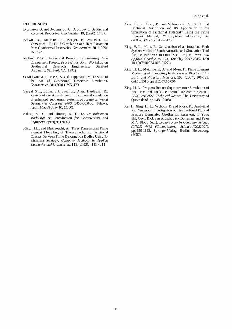
Figure 8 shows the permeability distribution of a certain geothermal reservoir calculated thorough the above microseismic events recorded. A virtual 8-well geothermal reservoir (i.e. 1 injection well + 7 production wells in a reservoir with the dimensions of Length x Width x Height: 4000mx3000mx1750m) is designed and further analysed by using PANDAS. The snapshots of the relevant results of fluid flow, hydraulic pressure variation and temperature distribution at the different stages are shown in Figures 9-11, respectively.
CONCLUSIONS
Based on the relevant surveys on geothermal reservoirs and the related computer modelling, the key improvements required in simulating an enhanced HDR/HFR/HWR geothermal reservoir system are discussed. Our research in an integrated geothermal reservoir simulator PANDAS for high performance simulation of enhanced geothermal reservoirs is introduced and then tested by the relevant cases. PANDAS is then applied in visualising the recorded microseismic events, monitoring and determining where/how the underground rupture proceeds during a hydraulic stimulation process, determining the domain of the ruptured zone and evaluating the material parameters (i.e. the permeability), and further in a virtual design and assessment of a multiple well reservoir system based on permeability distribution calculated from the recorded microseismic events. Both benchmark and application examples demonstrate its accuracy, stability and potential usefulness in simulating the enhanced geothermal reservoir systems.
Xing et al.
6
(a)
(b)
Figure 6: Visualization of the micro-seismicity data in a hydraulic stimulation process at the different time (days): (a) 16.417 and (b) 52.60.
Xing et al.
7
(a)
(b)
Figure 7: Visualization of the solid domain of the rupture zone occupied in a hydraulic stimulation process at the different time (days): (a) 16.417, and (b) 52.60.
Xing et al.
8
Figure 8: The calculated permeability distribution thorough the microseismic events recorded during a hydraulic stimulation process.
Figure 9: The simulated fluid flow in a certain fractured geothermal reservoir with 7 production wells and 1 injection well H1. It is calculated in 3D but shown in a certain cross-section here.
Xing et al.
9
Figure 10: The simulated hydraulic pressure distribution at the time of 23 days (above) and 5 years (below) in the fractured geothermal reservoir with 7 production wells and 1 injection well H1(Figure 9).
Xing et al.
10
(a)
(b)
Figure 11: The simulated temperature distribution at the time of (a) 10 years and (b) 40 years in the fractured geothermal reservoir with 7 production wells and 1 injection well H1 (Figure 9).
ACKNOWLEDGEMENTS
Support is gratefully acknowledged by the Australian Research Council and Geodynamics Limited through the ARC Linkage project LP0560932. The authors are grateful
to Drs Doone Wyborn, Hehua Xu, Wenhui Yu, Enlong Liu and Professor Hans Muhlhaus, for their discussion and collaboration in the relevant research.
Xing et al.
11
REFERENCES
Bjornsson, G. and Bodvarsson, G.: A Survey of Geothermal Reservoir Properties, Geothermics, 19, (1990), 17-27.
Brown, D., DuTeaux, R., Kruger, P., Swenson, D., Yamaguchi, T.: Fluid Circulation and Heat Extraction from Geothermal Reservoirs, Geothermics, 28, (1999), 553-572.
Molloy, M.W.: Geothermal Reservoir Engineering Code Comparison Project, Proceedings Sixth Workshop on Geothermal Reservoir Engineering, Stanford University. Stanford, CA (1982)
O’Sullivan M. J, Pruess, K. and. Lippmann, M. J.: State of the Art of Geothermal Reservoir Simulation. Geothermics, 30, (2001), 395–429.
Sanyal, S K, Butler, S J, Swenson, D and Hardeman, B.: Review of the state-of-the-art of numerical simulation of enhanced geothermal systems. Proceedings World Geothermal Congress 2000, 3853-3858pp. Tohoku, Japan, May28-June 10, (2000).
Sukop, M. C. and Thorne, D. T.: Lattice Boltzmann Modeling: An Introduction for Geoscientists and Engineers, Springer, (2007).
Xing, H.L., and Makinouchi, A.: Three Dimensional Finite Element Modelling of Thermomechanical Frictional Contact Between Finite Deformation Bodies Using R-minimum Strategy, Computer Methods in Applied Mechanics and Engineering, 191, (2002), 4193-4214
Xing, H. L., Mora, P. and Makinouchi, A.: A Unified Frictional Description and It's Application to the Simulation of Frictional Instability Using the Finite Element Method, Philosophical Magazine, 86, (2006a), (21-22), 3453-3475.
Xing, H. L., Mora, P.: Construction of an Intraplate Fault System Model of South Australia, and Simulation Tool for the iSERVO Institute Seed Project. Pure and Applied Geophysics. 163, (2006b), 2297-2316. DOI 10.1007/s00024-006-0127-x
Xing, H. L., Makinouchi, A. and Mora, P.: Finite Element Modelling of Interacting Fault System, Physics of the Earth and Planetary Interiors, 163, (2007), 106-121. doi:10.1016/j.pepi.2007.05.006
Xing, H. L.: Progress Report: Supercomputer Simulation of Hot Fractured Rock Geothermal Reservoir Systems, ESSCC/ACcESS Technical Report, The University of Queensland, pp1-48, (2008).
Xu, H, Xing, H. L., Wyborn, D and Mora, P.: Analytical and Numerical Investigation of Thermo-Fluid Flow of Fracture Dominated Geothermal Reservoir, in Yong Shi, Geert Dick van Albada, Jack Dongarra, and Peter M.A. Sloot (eds), Lecture Note in Computer Science (LNCS) 4489 (Computational Science-ICCS2007), pp1156-1163, Springer-Verlag, Berlin, Heidelberg, (2007).


![An integrated geothermal, gravity and aeromagnetic study ... · Geothermal data is one of the primary factors controlling hydrocarbon generation and migration [5, 6, 7]. Gravity and](https://static.documents.pub/doc/80x56/604cb08002dd244e8e501670/an-integrated-geothermal-gravity-and-aeromagnetic-study-geothermal-data-is.jpg)

![An efficient numerical simulator for geothermal simulation A … · Geothermal reservoir simulation entails the solution of mass and energy governing equations [3,4]. Due to the tight](https://static.documents.pub/doc/80x56/61356eb5dfd10f4dd73c5e88/an-efficient-numerical-simulator-for-geothermal-simulation-a-geothermal-reservoir.jpg)


