Date post: | 17-Aug-2019 |
Category: |
Documents |
Upload: | phungkhuong |
View: | 215 times |
Download: | 0 times |
TOYOTA YARIS3/5-DOORLIFTBACK 2008- HANDSFREEBLULOGICPreparation
Page1of11IssueA:08/31/10
Item2 Item3 Item5Item4
Part#:PT923-00111 NOTE:Partnumberofthisaccessorymaynotbethesameasthepartnumbershown.
Conflicts:JBLAudio,FactoryNavigation
KitContents:Forkitsmanufacturedonorafter19D0,installationkitswillincludeBLULogicSwitchDecal.Themanufacturingdatecodeisonthepartlabelofthepackagingboxandisprintedas“DDMY”.”PleasenotethatthismanufacturingdateisperToyotastandardsandisintheformatofDAY-DAY-MONTH-YEAR.Example:“31L8”dateonlabelmeans“31st,December,2008”.
HardwareContent
Item# QuantityReqd. Description
1 1 InterfaceModule2 1 MainPowerHarness3 1 BLULogicSwitch4 1 SwitchExtensionCable5 1 Microphone6 15 9.5”LockTies7 2 AdhesiveFoamPad8 1 Owner’sManual9 33cm 1/4”WireSplitLoom10 1 BLULogicDecal
AdditionalItems(mayberequired)
Item# QuantityReqd. Description
RecommendedSequenceofApplication
Item# Accessory
VehicleServiceParts(mayberequiredforreassembly)
Item# QuantityReqd. Description
LegendSTOP:Damagetothevehiclemayoccur.Donotproceeduntilpro-cesshasbeencompliedwith.
CAUTION:Aprocessthatmustbecarefullyobservedinordertoreducetheriskofdamagetotheaccessory/vehicle.
OPERATORSAFETY:Usecautiontoavoidriskofinjury.
TOOLS&EQUIPMENT:UsedinFigurestocalloutthespecifictoolsandequipmentrecommendedfortheprocess.
REVISIONMARK:Thismarkhighlightsachangeininstallationwithrespecttopreviousissue.
SAFETYTORQUE:Thismarkindicatesthattorqueisrelatedtosafety.
VIDEO:VideoAvailable;clicktoPlay
Item9
RecommendedToolsPersonal&VehicleProtection Notes
SafetyGoggles
SeatCovers
FloorCovers
SpecialTools
PanelClipRemoval SST#00002-06001-01
Sockets 8,10mm,Extension
Screwdriver Phillips#2,Flathead
SideCutters
TorqueWrench 36in-lb(4.07N.m)
InstallationTools Notes
MaskingTape VDCSupplied
FoamTape VDCSupplied
SpecialChemicals Notes
Cleaner VDCApprovedCleaner
GeneralApplicability
Note:
Item10
Item1 Item6 Item8Item7
TOYOTA YARIS3/5-DOORLIFTBACK 2008- HANDSFREEBLULOGICPreparation
Page2of11IssueA:08/31/10
TableofContents
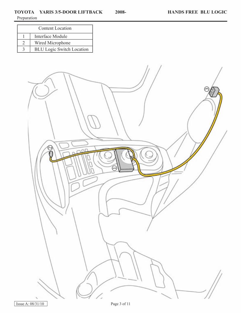
I. Preparation............................................................................................................................................... 1-21. TableOfContents..................................................................................................................................22. ContentLocation....................................................................................................................................3
II. Procedure................................................................................................................................................. 4-91. VehiclePreparation................................................................................................................................42. VehicleDisassembly..............................................................................................................................43. BLULogicSwitchInstallation..............................................................................................................64. MicrophoneInstallation.........................................................................................................................85. InterfaceModuleInstallation.................................................................................................................86. FinalizingtheInstallation......................................................................................................................97. ApplyBLULogicDecaltoSwitch......................................................................................................10
III.Checklist....................................................................................................................................................111. AccessoryFunctionChecks.................................................................................................................112. VehicleFunctionChecks......................................................................................................................11
AccessoryInstallationPractice(readbeforeinstallation)Caremustbetakenwheninstallingthisaccessorytoensuredamagedoesnotoccurtothevehicle.Theinstallationofthisaccessoryshouldfollowapprovedguidelinestoensureaqualityinstallation.
Theseguidelinescanbefoundinthe“AccessoryInstallationPractices”document.
Thisdocumentcoverssuchitemsas:• VehicleProtection(useofcoversandblankets,cleaningchemicals,etc.)• Safety(eyeprotection,checkingtorqueprocedure,etc.)• VehicleDisassembly/Reassembly(panelremoval,partstorage,etc.)• ElectricalComponentDisassembly/Reassembly(batterydisconnection,connectorremoval,etc.)
PleaseseeyourToyota/Scion/Lexusdealerforacopyofthisdocument.
TOYOTA YARIS3/5-DOORLIFTBACK 2008- HANDSFREEBLULOGICPreparation
Page3of11IssueA:08/31/10
ContentLocation
1 InterfaceModule2 WiredMicrophone3 BLULogicSwitchLocation
TOYOTA YARIS3/5-DOORLIFTBACK 2008- HANDSFREEBLULOGICProcedure
Page4of11IssueA:08/31/10
1. VehiclePreparation(Fig.1-1)
a. Applyparkingbrake.b. Protectfenderbeforestarting.c. Removethenegative(–)batterycable.
CAUTION:Donottouchthepositivetermi-nalwithanytoolduringremoval.d. Usingtheprotectiveblanket,coverfront
seat,sideoftheshiftleverandcenterconsole.
e. Placeremovedvehiclecomponentsonaprotectiveblanket.
Fig. 1-1
3.Usinghandsorappropriatepanelremovaltool,disengagetherightsidetrimgarnish(Fig.1-3).
4.Disconnectanyconnectorsandre-move.
NOTE:Ifusingpanelremovaltool,applyprotectivetapetothepryarea(s).
2. VehicleDisassembly
a. Removethecenterclustersidetrimgarnishes.
1.Usinghandsorappropriatepanelre-movaltool,disengagetheleftsidetrimgarnish(Fig.1-2).
2.Disconnectanyconnectorsandre-move.
NOTE:Ifusingpanelremovaltool,applyprotectivetapetothepryarea.
Socket(10mm),Ratchet
Fig. 1-3
Fig. 1-2
PanelRemovalTool
PanelRemovalTool
TOYOTA YARIS3/5-DOORLIFTBACK 2008- HANDSFREEBLULOGICProcedure
Page5of11IssueA:08/31/10
b. Removetheclusterbezel.
1.Usingyourhands,gentlypullontheleftandrightcornerofthebezeltodisengage.
2.Liftthefrontlipofthebezeluptodisengagethethree(3)locktabsandremovethebezel(Fig.1-4).
Fig. 1-4
d. RemovetheHVACassembly.
1.Usinghands,disengagetheHVACas-sembly(Fig.1-6).
2.MovetheHVACassemblyasideoruseotherappropriatemeanstopreventanydamagetotheconnectionsaswellaspreventingscratches.
NOTE:HVACassemblywascompletelyremovedforphotopurposesonly.DONOTDISCONNECTANYHVACCONNEC-TORS.
c. Removetheradiobezel.
1.Usinghands,disengagetheradiobezelandremove(Fig.1-5).
Fig. 1-5
Fig. 1-6
TOYOTA YARIS3/5-DOORLIFTBACK 2008- HANDSFREEBLULOGICProcedure
Page6of11IssueA:08/31/10
e. Removetheradioassembly.
1.Usingan8mmsocket/ratchetorPhil-lipsscrewdriver,removefour(4)boltssecuringtheradio(Fig.1-7).
2.Disconnectallconnectorsandsetaside.
NOTE:Becarefulnottoputtoomuchten-sionontheconnections.
Fig. 1-7
3.Usinghands,pulluponthefrontofthecenterfloorconsoletodislodge(Fig.1-9).
4.Disconnectanyconnectorsandre-move.
NOTE:Onvehiclesequippedwithamanualtransmission,theshiftknobmustbeun-screwedbeforethecenterfloorconsolecanberemoved.
5.MoveshiftlevertotheNeutralposi-tion.
3. BLULogicSwitchInstallation
a. Removecenterfloorconsole.
1.Removeclothinsertinthecupholder(Fig.1-8).
2.Usinga10mmsocket/ratchet,removetheboltunderneaththeclothinsert.
Fig. 1-8
Fig. 1-9
Socket(8mm),RatchetofPhillipsScrewdriver
Socket(10mm),Ratchet
TOYOTA YARIS3/5-DOORLIFTBACK 2008- HANDSFREEBLULOGICProcedure
Page7of11IssueA:08/31/10
b. Routeswitchcable(highlightedinor-ange).
1.Followingtheexistingwireloom,routetheswitchcableuptowardstheopen-ingoftheHVACcavity(Fig.1-10)
2.Leavea3-4inchpigtail(shifterside)thatwillconnecttotheswitchlater.
3.SecureswitchcabletoexistingwireloomwithwiretiescircledinFig.1-10.
4.Wiretieevery5-6inchesandcutoffexcesswireties.Fig. 1-10
3.Reinstallthecenterfloorconsole.
4.Connecttheswitchtothepigtailandreinstalltheswitchpanel(Fig.1-12).
c. MounttheBLULogicswitch.
1.Removetheswitchpanelonthecenterfloorconsolebydisengagingtheclipswithhand.
2.Removelowerleftblankknock-outandmounttheswitchwiththesolidar-rowpointingforward(Fig.1-11).
NOTE:Usenextavailableblankknock-outiflowerleftisoccupied.
Fig. 1-11
Fig. 1-12
SideCutters
TOYOTA YARIS3/5-DOORLIFTBACK 2008- HANDSFREEBLULOGICProcedure
Page8of11IssueA:08/31/10
SideCutters
SideCutters 4. MicrophoneInstallationa. Routethemicrophone(highlightedinblue).
1. Apply33cmof1/4”splitwireloomtothemicrophoneendofthecable.
2. Leaveaminimumof8mmofwireex-posed.Securewireloomwithtape.
3. RoutemicrophonetotherightoftheHVACairvents,downtowardstheradioopening(Fig.1-13).
4. FollowandsecuretoexistingwireloomwithtwowiretiescircledinFig.1-13.
NOTE:BLULogicwiretiesinFigure1-13andtheremainderoftheseinstructionswillbeshowninyellow.
Fig. 1-13
3.Mountmoduletothevehicle’sharnesshighlightedinorange(Fig.1-15).
5. InterfaceModuleInstallation
a. Mounttheinterfacemodule.
1. Insertthree(3)wiretiesthroughthemountingpointsontheinterfacemod-ule(Fig.1-14).
2.Connectthemainwireharness,micro-phoneandswitchwiretotheirrespec-tiveconnectionlocations.
NOTE:TheRedconnectorisconnectedtothematchingRedconnectoronthemodule.
DONOTremoveprotectivefoamwrapfrommodule.Fig. 1-14
Fig. 1-15
SideCutters
TOYOTA YARIS3/5-DOORLIFTBACK 2008- HANDSFREEBLULOGICProcedure
Page9of11IssueA:08/31/10
b. Routemainwireharness(highlightedinorange).
1.Routemainharnesstotheleftofthemoduleuptowardsthevehicle’sradioconnectors(Fig.1-16).
2.Connectthemainwireharnesstothevehicle’sradioconnectorsasneeded.
3.Bundleexcessmicrophoneharness(highlightedinblue)andsecureittothemainwireharness(circledinFig.1-16).
Fig. 1-16
6. FinalizetheInstallationa. Connectthemainwireharnesstothera-
dio’smatchingconnectionsasneeded.
NOTE:AVC-LAN(12pin)connectormaynotbepresentonthevehicle’sharness.Wiretiethisconnectortotheharnessunconnected,butALWAYSconnecttheAVC-LAN(12pin)con-nectorintotheradio.
IfAVC-LAN(12pin)connectorispresentonvehicleharness,connecttojumperprovidedwithBLULogicunit.b. Reinstalltheradio.
NOTE:Ifanyotheraccessoriesareinstalledthatconnecttotheheadunit,BLULogicshouldbetheunitthatplugsintotheradiofirst.c. ReinstallHVACassemblyandradiobezel.d. Mountthemicrophone.
1. CleantheclusterbezelwithVDCap-provedcleaner.
2.Mountthemicrophonetotheimmedi-ateleftofthefeaturelinemarkedbythearrow.Themicrophoneshouldbeaminimumof0-5mmfromthefeatureline.Aligntherearofthemicrophonewiththebackedgeofthetrimpaneltominimizetheamountofexposedwirevisibletothecustomer.0-8mmofexposedwireisac-ceptable(Fig.1-17).
e. Reinstallthebezelandsidetrimgarnishes.f. Positionnegativebatteryterminalatthe
originalfactoryposition(tightenthenutto36in-lbs(4.07N.m).
CAUTION:Donottouchthepositiveterminalwithanytoolduringinstallation.g. Placeowner’smanualintheglovebox.
Fig. 1-17
SideCutters
TOYOTA YARIS3/5-DOORLIFTBACK 2008- HANDSFREEBLULOGICProcedure
Page10of11IssueA:08/31/10
7. ApplyBLULogicdecaltoBLULogicswitch.(OnlykitsmanufacturedonorafterthedatecodeonthefrontpagewillincludetheBLULogicdecal).
a. RemovetheprotectivebackingontheroundportionoftheBLULogicsticker(Fig.1-18).
b. ApplyittothecenteroftheswitchsothatthestickerhangstowardstherightasshowninFig.1-19.
NOTE:Photoshownmaynotmatchtheswitchinstallationlocationforthisvehicleandisforillustrativepurposes.
Fig. 1-18
Fig. 1-19
TOYOTA YARIS3/5-DOORLIFTBACK 2008- HANDSFREEBLULOGICCHECKLIST–thesepointsMUSTbecheckedtoensureaqualityinstallation.
Page11of11IssueA:08/31/10
AccessoryFunctionChecks
Check: LookFor:
FactoryRadio TurnontheradioandverifythattheBLULogicModulewillmutetheaudio.Withtheradioon,pressthemiddlebuttonontheBLULogicswitchandverifythattheaudioismuted.
InterfaceKit
VerifytheproperconnectionoftheInterfacekitbypressingandholdingthemiddlebuttonontheswitchuntilyouhearone(1)beep.
NOTE:Pairingthemoduletoaphoneisnotrequired.Thisisthecustomers(ordealers)respon-sibility.
AudioOutput TurntheradiotoanAMorFMstationandthenturnthebalancetotheLandconfirmtheaudioiscomingfromtheleftfrontspeaker.Repeatfortherightfrontspeaker.
VehicleFunctionCheck
VehicleFunction VehicleFunctionDetail
AudioAM/FM VerifytheproperoperationofaudioAM/FM.
HazardSwitch Verifytheproperoperationofthehazardswitch.
HVAC Verifytheproperoperationoftheairconditioningsystem.
DoorLockSwitch Verifytheproperoperationofthedoorlockswitch.
NAVSystem(ifequipped) ConfirmnavigationoperationbyAVNdiagnostics.
SRSWarningLight ConfirmSRSwarninglightilluminatesforapproximately6secondswiththeignitionON,andthengoesout.
TirePressureMonitoringSystem(TPMS) Prior to TPMS activation and Pre- delivery Service (PDS) of the Vehicle the TPMS light will blink when IG is turned on.After TPMS activation and PDS of the Vehicle the TPMS light will illuminate for a few seconds and go off when IG is turned on.
KitServiceInformation
Item: Location:
1 3-Ampin-lineFuse Thefuseislocatedbehindtheradioassembly.Toreplace,fol-lowStep1through7toaccessthefuselocation.
NOTE:Ifthefuseisblown,theHandsFreeBLULogicwillnotturnon.
Makesureradioandinteriorlights(ifapplicable)areturnedoff.Installfuse(shortpin)forthefollowingfunctionchecks.
Turnoffallcomponentsincludingradioandinteriorlights.Removefuse(shortpin)afterfunctionchecksarecomplete.Checkwithyourdealer/porttofindoutifthisstepisrequired.