42
ETSI TR 101 301 V3.1.1 (2004-04) Technical Report Telecommunications and Internet Protocol Harmonization Over Networks (TIPHON) Release 4; Release Definition; TIPHON Release 4 Definition
ETSI TR 101 301 V3.1.1 (2004-04)
Technical Report
Telecommunications and Internet ProtocolHarmonization Over Networks (TIPHON) Release 4;
Release Definition;TIPHON Release 4 Definition

ETSI
ETSI TR 101 301 V3.1.1 (2004-04) 2
Reference RTR/TISPAN-01010-TIPHON_R4
Keywords internet, IP, PSTN, speech, telephony, VoIP
ETSI
650 Route des Lucioles F-06921 Sophia Antipolis Cedex - FRANCE
Tel.: +33 4 92 94 42 00 Fax: +33 4 93 65 47 16
Siret N° 348 623 562 00017 - NAF 742 C
Association à but non lucratif enregistrée à la Sous-Préfecture de Grasse (06) N° 7803/88
Important notice
Individual copies of the present document can be downloaded from: http://www.etsi.org
The present document may be made available in more than one electronic version or in print. In any case of existing or perceived difference in contents between such versions, the reference version is the Portable Document Format (PDF).
In case of dispute, the reference shall be the printing on ETSI printers of the PDF version kept on a specific network drive within ETSI Secretariat.
Users of the present document should be aware that the document may be subject to revision or change of status. Information on the current status of this and other ETSI documents is available at
http://portal.etsi.org/tb/status/status.asp
If you find errors in the present document, send your comment to: [email protected]
Copyright Notification
No part may be reproduced except as authorized by written permission. The copyright and the foregoing restriction extend to reproduction in all media.
© European Telecommunications Standards Institute 2004.
All rights reserved.
DECTTM, PLUGTESTSTM and UMTSTM are Trade Marks of ETSI registered for the benefit of its Members. TIPHONTM and the TIPHON logo are Trade Marks currently being registered by ETSI for the benefit of its Members. 3GPPTM is a Trade Mark of ETSI registered for the benefit of its Members and of the 3GPP Organizational Partners.

ETSI
ETSI TR 101 301 V3.1.1 (2004-04) 3
Contents
Intellectual Property Rights ................................................................................................................................4
Foreword.............................................................................................................................................................4
1 Scope ........................................................................................................................................................5
2 References ................................................................................................................................................5
3 Abbreviations ...........................................................................................................................................8
4 An overview of the TIPHON approach....................................................................................................9 4.1 Basic TIPHON Scenarios .................................................................................................................................10 4.1.1 Scenario 1: VoIP call to SCN user..............................................................................................................11 4.1.2 Scenario 2: SCN call to VoIP user..............................................................................................................11 4.1.3 Scenario 3: SCN call to SCN user via a VoIP network ..............................................................................12 4.1.4 Scenario 0: VoIP call to VoIP user .............................................................................................................12 4.2 The TIPHON "Tool Box".................................................................................................................................13 4.3 A simple TIPHON reference model .................................................................................................................13 4.3.1 TIPHON network element ..........................................................................................................................13 4.3.2 Reference model .........................................................................................................................................14
5 Release 4 ................................................................................................................................................15 5.1 Document type definitions ...............................................................................................................................15 5.2 Definition of terms ...........................................................................................................................................15 5.3 TIPHON Release 4 Work Items .......................................................................................................................16
Annex A: TIPHON Release 4................................................................................................................20
A.1 Background ............................................................................................................................................20 A.1.1 TIPHON Releases 1 and 2................................................................................................................................21 A.1.2 TIPHON Release 3...........................................................................................................................................21
A.2 The TIPHON Release 4 process.............................................................................................................21
A.3 Release definition (Step A) ....................................................................................................................22 A.3.1 Simple call requirements ..................................................................................................................................23 A.3.1.1 Naming .......................................................................................................................................................23 A.3.1.2 Quality of Service .......................................................................................................................................24 A.3.1.3 Security .......................................................................................................................................................25
A.4 Capabilities and requirements (Step B)..................................................................................................26 A.4.1 Domains ...........................................................................................................................................................27 A.4.2 Functional groups .............................................................................................................................................27 A.4.3 Introduction to the TIPHON transport plane ....................................................................................................27
A.5 Reference architecture (Step C) .............................................................................................................28 A.5.1 Service capability example...............................................................................................................................29 A.5.2 User roaming considerations ............................................................................................................................30 A.5.3 TIPHON Scenario 0 functional groups ............................................................................................................31 A.5.4 TIPHON Scenario 1 functional groups ............................................................................................................32 A.5.5 TIPHON Scenario 2 functional groups ............................................................................................................32 A.5.6 TIPHON Scenario 3 functional groups ............................................................................................................32
A.6 Implementation framework (Step D) .....................................................................................................33 A.6.1 Basic call example............................................................................................................................................36
A.7 Technology mapping and verification (Step E)......................................................................................37 A.7.1 Mapping to standard protocols and entities ......................................................................................................38
Annex B: Bibliography..........................................................................................................................41
History ..............................................................................................................................................................42

ETSI
ETSI TR 101 301 V3.1.1 (2004-04) 4
Intellectual Property Rights IPRs essential or potentially essential to the present document may have been declared to ETSI. The information pertaining to these essential IPRs, if any, is publicly available for ETSI members and non-members, and can be found in ETSI SR 000 314: "Intellectual Property Rights (IPRs); Essential, or potentially Essential, IPRs notified to ETSI in respect of ETSI standards", which is available from the ETSI Secretariat. Latest updates are available on the ETSI Web server (http://webapp.etsi.org/IPR/home.asp).
Pursuant to the ETSI IPR Policy, no investigation, including IPR searches, has been carried out by ETSI. No guarantee can be given as to the existence of other IPRs not referenced in ETSI SR 000 314 (or the updates on the ETSI Web server) which are, or may be, or may become, essential to the present document.
Foreword This Technical Report (TR) has been produced by ETSI Technical Committee Telecommunications and Internet converged Services and Protocols for Advanced Networking (TISPAN).

ETSI
ETSI TR 101 301 V3.1.1 (2004-04) 5
1 Scope The present document provides a description of the content of TIPHON Release 4 and shows the relevant documents and their inter-relationships.
Each TIPHON release builds upon and extends the previous release. In this manner Release N contains and extends Release N-1, and is itself extended by Release N+1.
The present document is structured as follows:
• clause 4 introduces the release plan documentation set;
• clause 5 defines the content and capabilities of TIPHON Release 4.
The present document does not provide solutions for the technical issues that are identified therein.
The present document is prepared in accordance with the TIPHON project method defined in TR 101 835 [1] and fulfils the requirements of Step A.
In addition, the present document contains a comprehensive overview and description of the technical aspects of TIPHON Release 4.
2 References For the purposes of this Technical Report (TR) the following references apply:
[1] ETSI TR 101 835: "Telecommunications and Internet Protocol Harmonization Over Networks (TIPHON); Project method definition".
[2] ETSI EN 300 089: "Integrated Services Digital Network (ISDN); Calling Line Identification Presentation (CLIP) supplementary service; Service description".
[3] ETSI EN 300 094: "Integrated Services Digital Network (ISDN); Connected Line Identification Presentation (COLP) supplementary service; Service description".
[4] ETSI ETS 300 140: "Integrated Services Digital Network (ISDN); Call Hold (HOLD) supplementary service; Functional capabilities and information flows".
[5] ETSI EN 300 357: "Integrated Services Digital Network (ISDN); Completion of Calls to Busy Subscriber (CCBS) supplementary service; Service description".
[6] ETSI ETS 300 134: "Integrated Services Digital Network (ISDN); Signalling System No.7; Transaction Capabilities Application Part (TCAP)".
[7] ETSI EN 301 133: "Integrated Services Digital Network (ISDN); Selective Call Forwarding (SCF) supplementary service (unconditional, busy and no reply); Service description".
[8] ETSI EN 300 199: "Integrated Services Digital Network (ISDN); Call Forwarding Busy (CFB) supplementary service; Service description".
[9] ETSI ETS 300 200: "Integrated Services Digital Network (ISDN); Call Forwarding Unconditional (CFU) supplementary service; Service description".
[10] ETSI EN 300 201: "Integrated Services Digital Network (ISDN); Call Forwarding No Reply (CFNR) supplementary service; Service description".
[11] ETSI ETS 300 202: "Integrated Services Digital Network (ISDN); Call Deflection (CD) supplementary service; Service description".
[12] ETSI EN 301 082: "Integrated Services Digital Network (ISDN); Outgoing Call Barring-Fixed (OCB-F) supplementary service; Service description".

ETSI
ETSI TR 101 301 V3.1.1 (2004-04) 6
[13] ETSI EN 301 798 (V1.1.1): "Services and Protocols for Advanced Networks (SPAN); Anonymous Call Rejection (ACR) Supplementary Service; Service description".
[14] ETSI ETS 300 056: "Integrated Services Digital Network (ISDN); Call Waiting (CW) supplementary service; Service Description".
[15] ETSI ETS 300 186: "Integrated Services Digital Network (ISDN); Three-Party (3PTY) supplementary service; Service description".
[16] ETSI ETS 300 178: "Integrated Services Digital Network (ISDN); Advice of Charge: charging information at call set-up time (AOC-S) supplementary service; Service description".
[17] ETSI ETS 300 179: "Integrated Services Digital Network (ISDN); Advice of Charge: charging information during the call (AOC-D) supplementary service; Service description".
[18] ETSI ETS 300 180: "Integrated Services Digital Network (ISDN); Advice of Charge: charging information at the end of the call (AOC-E) supplementary service; Service description".
[19] ETSI TS 101 331: "Telecommunications security; Lawful Interception (LI); Requirements of Law Enforcement Agencies".
[20] ETSI TR 101 750: "Telecommunications and Internet Protocol Harmonization Over Networks (TIPHON); Requirements Definition Study; Studies into the Impact of lawful interception".
[21] ETSI EN 300 924 (Edition 3): "Digital cellular telecommunications system (Phase 2+) (GSM); enhanced Multi-Level Precedence and Pre-emption Service (eMLPP) - Stage 1".
[22] ETSI TR 101 300: "Telecommunications and Internet Protocol Harmonization Over Networks (TIPHON); Description of Technical Issues".
[23] IETF RFC 2543: "SIP: Session Initiation Protocol".
[24] ETSI TS 101 882: "Telecommunications and Internet Protocol Harmonization Over Networks (TIPHON) Release 3; Protocol Framework Definition; General (meta-protocol)".
[25] ETSI TS 101 314: "Telecommunications and Internet Protocol Harmonization Over Networks (TIPHON) Release 4; Abstract Architecture and Reference Points Definition; Network Architecture and Reference Points".
[26] ETSI TR 102 008: "Telecommunications and Internet Protocol Harmonization Over Networks (TIPHON) Release 3; Terms and Definitions".
[27] ITU-T Recommendation H.323: "Packet-based multimedia communications systems".
[28] ITU-T Recommendation E.164: "The international public telecommunication numbering plan".
[29] ETSI TR 101 326: "Telecommunications and Internet Protocol Harmonization Over Networks (TIPHON); The procedure for determining IP addresses for routeing packets on interconnected IP networks that support public telephony".
[30] ETSI TR 101 858: "Telecommunications and Internet Protocol Harmonization Over Networks (TIPHON); Number portability and its implications for TIPHON networks".
[31] ETSI TR 101 329-1: "Telecommunications and Internet Protocol Harmonization Over Networks (TIPHON) Release 3; End-to-end Quality of Service in TIPHON systems; Part 1: General aspects of Quality of Service (QoS)".
[32] ITU-T Recommendation E.600: "Terms and definitions of traffic engineering".
[33] ITU-T Recommendation G.107: "The E-Model, a computational model for use in transmission planning".
[34] ITU-T Recommendation P.310: "Transmission characteristics for telephone band (300 - 3 400 Hz) digital telephones".
ETSI
ETSI TR 101 301 V3.1.1 (2004-04) 7
[35] ETSI TS 101 329-5: "Telecommunications and Internet Protocol Harmonization Over Networks (TIPHON) Release 3; End-to-end Quality of Service in TIPHON systems; Part 5: Quality of Service (QoS) measurement methodologies".
[36] ETSI TS 101 329-2: "Telecommunications and Internet Protocol Harmonization Over Networks (TIPHON) Release 3; End-to-end Quality of Service in TIPHON systems; Part 2: Definition of speech Quality of Service (QoS) classes".
[37] ETSI TR 101 329-7: "Telecommunications and Internet Protocol Harmonization Over Networks (TIPHON) Release 3; End-to-end Quality of Service in TIPHON systems; Part 7: Design guide for elements of a TIPHON connection from an end-to-end speech transmission performance point of view".
[38] ETSI TS 101 329-3: "Telecommunications and Internet Protocol Harmonization Over Networks (TIPHON) Release 3; End-to-end Quality of Service in TIPHON systems; Part 3: Signalling and control of end-to-end Quality of Service (QoS)".
[39] IETF RFC 2401: "Security Architecture for the Internet Protocol".
[40] IETF RFC 2246: "The TLS Protocol Version 1.0".
[41] ITU-T Recommendation H.235: "Security and encryption for H-Series (H.323 and other H.245-based) multimedia terminals".
[42] ETSI TR 101 877: "Telecommunications and Internet Protocol Harmonization Over Networks (TIPHON); Requirements Definition Study; Scope and Requirements for a Simple call".
[43] ETSI TR 101 311: "Telecommunications and Internet Protocol Harmonization Over Networks (TIPHON) Release 3; Service Independent requirements definition; Transport Plane".
[44] ETSI TS 101 878: "Telecommunications and Internet Protocol Harmonization Over Networks (TIPHON) Release 4; Service Capability Definition; Service Capabilities for TIPHON Release 4".
[45] ETSI TS 101 315: "Telecommunications and Internet Protocol Harmonization Over Networks (TIPHON) Release 4; Information flow and reference point definitions; Implementation of service capabilities".
[46] ETSI ETR 298: "Methods for Testing and Specification (MTS); Specification of protocols and services; Handbook for SDL, ASN.1 and MSC development".
[47] ITU-T Recommendation Q.931: "ISDN user-network interface layer 3 specification for basic call control".
[48] ITU-T Recommendation H.225.0: "Media stream packetization and synchronization on non-guaranteed quality of service LANs".
[49] ITU-T Recommendation H.245: "Control protocol for multimedia communication".
[50] ITU-T Recommendation H.248: "Gateway control protocol".
[51] IETF RFC 2327: "SDP: Session Description Protocol".
[52] IETF RFC 3015: "Megaco Protocol Version 1.0".
[53] ETSI TS 101 883: "Telecommunications and Internet protocol Harmonization Over Networks (TIPHON) Release 4; Technology Mapping; Implementation of TIPHON architecture using H.323".
[54] ETSI TS 101 884: "Telecommunications and Internet Protocol Harmonization Over Networks (TIPHON) Release 3; Technology Mapping; Implementation of TIPHON architecture using SIP".
[55] ETSI TS 101 885: "Telecommunications and Internet Protocol Harmonization Over Networks (TIPHON) Release 4; Interface Protocol Requirements Definition; Implementation of TIPHON using H.248/MEGACO".

ETSI
ETSI TR 101 301 V3.1.1 (2004-04) 8
[56] Void.
[57] ETSI TS 101 520: "Telecommunications and Internet Protocol Harmonization Over Networks (TIPHON); Implementation Conformance Statement (ICS) proforma for the support of packet based multimedia communications systems; Support of ITU-T Recommendation H.323".
[58] ETSI TS 101 521: "Telecommunications and Internet Protocol Harmonization Over Networks (TIPHON); Protocol Implementation Conformance Statement (PICS) proforma for the support of call signalling protocols and media stream packetization for packet-based multimedia communication systems; Support of ITU-T Recommendation H.225.0".
[59] ETSI TS 101 522: "Telecommunications and Internet Protocol Harmonization Over Networks (TIPHON); Protocol Implementation Conformance Statement (PICS) proforma for the support of control protocol for multimedia communication; Support of ITU-T Recommendation H.245".
[60] ETSI EG 201 058: "Methods for Testing and Specification (MTS); Implementation Conformance Statement (ICS) proforma style guide".
[61] ETSI ETR 266: "Methods for Testing and Specification (MTS); Test Purpose style guide".
[62] ETSI EG 202 103: "Methods for Testing and Specification (MTS); Guide for the use of the second edition of TTCN".
[63] ETSI ETR 141: "Methods for Testing and Specification (MTS); Protocol and profile conformance testing specifications; The Tree and Tabular Combined Notation (TTCN) style guide".
3 Abbreviations For the purposes of the present document, the following abbreviations apply:
API Application Programming Interface ASN1 Abstract Syntax Notation One ATS Abstract Test Suite ATS Abstract Test Suite BC Bearer Control BICC Bearer Independent Call Control CC Call Control CCBS Completion of Call to BusySubscriber CCNR Completion of Call on NoReply CLI Calling Line Identification CLIP Calling Line Identification Presentation CLIR Calling Line Identification Restriction CUG Closed User Group DSS1 Digital Subscriber Signalling One ETS Executable Test Suite GSM Global System for Mobile communications ICANN Internet Corporation for Assigned Names and Numbers ICLID Incoming Call LineID ICS Implementation Conformance Statement IN Intelligence Network INAP Intelligent Natwork Application Part IP Internet Protocol ISDN Integrated Services Digital Network ISUP Integrated Switched Digital Network User Part ITSP IP Telephony Service Provider IXIT Implementation eXtra Information for Testing LI Lawful Interception MC Media Control MSC Message Sequence Charts OSP Open SettlementProtocol PICS Protocol Implementation Conformance Statement

ETSI
ETSI TR 101 301 V3.1.1 (2004-04) 9
PSTN Public Switched Telephone Network PT Packet Telephony QoS Quality of Service RTP Real-time TransportProtocol SAP Service Access Point SC Service Control SCN Switched Circuit Network SDL Specification and Description Language SDP Service DatatPoint SE Services SIP Session Initiation Protocol TCC TIPHON Call Control TCC-SAP TIPHON Call Control Service Access Point TLL TIPHON Lower Layer TLL-SAP TIPHON Lower Layer Service Access Point TLS Transport Layer Security TNO Transport Network Operator TR TIPHON Registration TR-SAP TIPHON Registration Service Access Point TSS&TP Test Suite Structure and Test Purposes TT TIPHON Transport TT-SAP TIPHON Transport Service Access Point UML Unified ModellingLanguage VoIP Voice over IP
4 An overview of the TIPHON approach Release 3 was the first major edition of TIPHON documentation to be made publicly available and, as such, represents a considerable amount of effort from the members of the TIPHON Project. Release 4 adds several new service capabilities to enable a feature-rich portfolio of services to be constructed using the TIPHON specifications.

ETSI
ETSI TR 101 301 V3.1.1 (2004-04) 10
Several additional telephony-related requirements for support in TIPHON Release 4 have been identified and include:
Support for Enhanced Residential Service Calling Number /Name Presentation (CLI / ICLID etc.) [2] Connected Line Presentation/Restriction [3] Message waiting Message Indication Call Return Call Hold [4] Transfer Ring-Back (Auto Callback, CCBS, CCNR) [5]; [6] Call Forward (UC/C/B/DA/V/NR, Deflect) [7], [8], [9], [10] and [11] Call Barring (Outgoing) (Soft Dial-Tone) [12] Call Barring (Incoming) ACI, ACR, Selective, etc. [13] Call Barring (Incoming) Bypass Alarm/Reminder Call Distinctive Alert (Call Sign) Call Waiting Indication [14] Terminal Portability 3-way Conference (n-way) [15] Call Trace (Malicious Call ID) Advice of duration and charge [16], [17] and [18] Multiple subscriber numbers Network Redial FAX In-band Data Transport (Modem pass-through)
Support for SME: Basic Business Service Features in High-end residential Plus: Account Codes Call Park Call Pick-up (Group/Directed) Short Code (Dialling Plans) Hunt Groups Closed User Group (CUG)
Service Provider Operational Capabilities Line Service (General) Interrogation Call Trace Barge-In (n/a) Howler
The following are deferred to a subsequent TIPHON release:
• APIs;
• Multi-media;
• Instant messaging.
These Key requirements include naming and numbering policies, Quality of Service, Lawful Interception [19] and [20] emergency and priority calls [21] and security.
4.1 Basic TIPHON Scenarios In order to establish the requirements for service creation, architecture, signalling and service support in a TIPHON environment, it is necessary to consider four basic scenarios [22] from which all other (more complex) scenarios can be derived. These basic scenarios are:
• Scenario 1: simple call from a user in a Voice over IP (VoIP) network to another user in an adjacent Switched Circuit Network (SCN) such as ISDN.
ETSI
ETSI TR 101 301 V3.1.1 (2004-04) 11
• Scenario 2: simple call from a user in a SCN, to another user in an adjacent VoIP network using SIP or a similar protocol.
• Scenario 3: call from a user in a SCN to a user in another SCN where the call is routed through one or more transit networks of which at least one is a VoIP network.
• Scenario 0: call from a user in a VoIP network is routed to another user in a different VoIP network.
In each of these scenarios (see figures 1 to 4), the interface between the disparate networks is identified as a "TIPHON Gateway". In real-world implementations this may or may not be a separate item of physical equipment but it is the interoperation of both protocol and media at this point that is a focus of TIPHON standardization.
The other focus of TIPHON is the behaviour within the domains (especially those on IP technology) where the current state of the art is not mature enough that it allows proper interworking with the SCN.
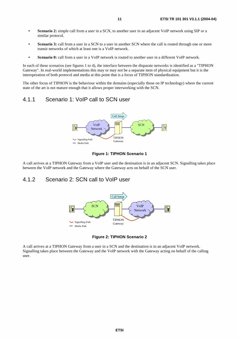
4.1.1 Scenario 1: VoIP call to SCN user
VoIPNetwork
VoIPNetwork
TIPHON Gateway
Call Setup
SCNSCN
Signalling Path
Media Path
Figure 1: TIPHON Scenario 1
A call arrives at a TIPHON Gateway from a VoIP user and the destination is in an adjacent SCN. Signalling takes place between the VoIP network and the Gateway where the Gateway acts on behalf of the SCN user.
4.1.2 Scenario 2: SCN call to VoIP user
SCNSCN VoIPNetwork
VoIPNetwork
TIPHON Gateway
Call Setup
Signalling Path
Media Path
Figure 2: TIPHON Scenario 2
A call arrives at a TIPHON Gateway from a user in a SCN and the destination is in an adjacent VoIP network. Signalling takes place between the Gateway and the VoIP network with the Gateway acting on behalf of the calling user.

ETSI
ETSI TR 101 301 V3.1.1 (2004-04) 12
4.1.3 Scenario 3: SCN call to SCN user via a VoIP network
TIPHON Gateway
Call Setup
TIPHON Gateway
SCNSCN VoIPNetwork
VoIPNetwork
SCNSCN
Signalling Path
Media Path
Figure 3: TIPHON Scenario 3
A call from one SCN user to another SCN user passes through at least one VoIP network, transiting a TIPHON gateway at each network interworking boundary. The gateways act on behalf of the SCN users in their negotiations with the VoIP network(s). This scenario is essentially a combination of Scenarios 1 and 2.
4.1.4 Scenario 0: VoIP call to VoIP user
This scenario is shown in figure 4 and is referred to as TIPHON Scenario 0.
TIPHON Gateway
Call Setup
VoIPNetwork
VoIPNetwork
VoIPNetwork
VoIPNetwork
Signalling Path
Media Path
Figure 4: TIPHON Scenario 0

ETSI
ETSI TR 101 301 V3.1.1 (2004-04) 13
4.2 The TIPHON "Tool Box" In order to achieve interworking between existing SCN technologies (for example, DSS1) and IP media technologies (for example, SIP [23]) as well as possible future technologies, TIPHON has specified a meta-protocol which provides communication between the two sides of a TIPHON Gateway. Although it is unlikely, and unnecessary, that any TIPHON-compliant equipment will implement the meta-protocol, a protocol that has been mapped to the meta-protocol should also interwork with any other protocol that is also mapped to the meta-protocol. It is these mappings and the profile standards (closing options and identifying limitations) that are the key outputs of the overall TIPHON process. This process, as shown in figure 5, can be viewed as a tool box taking a set of fixed TIPHON requirements and a range of technology-specific inputs to produce mapping and profile standards with their associated test suites.
TIPHONTool Box
RequirementsProtocol
Architecture
Numbering
Security
QoS
Services
Mapping and
Profiles
ProfileTest Suites
Technology Standards
Figure 5: The TIPHON "Tool Box"
Although some mapping and profile standards are included in the TIPHON project deliverables, the meta-protocol is published as an open standard so that any standardization body may prepare TIPHON mapping and profile standards for any communication protocol that they have responsibility for.
4.3 A simple TIPHON reference model
4.3.1 TIPHON network element
A review of the scenarios shown in figure 1 to 4 is helpful in determining the basic modelling aspects which are required for the development of the TIPHON protocol framework [24]. In generic terms, each network involved in a TIPHON environment can be considered, with its TIPHON Gateway(s), to be a "black-box" as shown in figure 6.
TIPHON Gateway
NetworkNetwork
TIPHON GatewaySignalling Path
Media Path
Figure 6: TIPHON network element

ETSI
ETSI TR 101 301 V3.1.1 (2004-04) 14
A special case of this black-box is a network connected to a TIPHON gateway on one side but to a user on the other, as shown in figure 7.
NetworkNetwork
TIPHON Gateway
User
Signalling Path
Media Path
Figure 7: TIPHON network element with Gateway and user
The TIPHON network element shown in figure 7 is further refined into 2 elements representing the calling user's network and the called user's network, as shown in figure 8.
NetworkNetwork
TIPHON Gateway
Called User
NetworkNetwork
TIPHON Gateway
Calling User
Signalling Path
Media Path
Figure 8: Origination and destination TIPHON network elements
4.3.2 Reference model
Any of the scenarios in figure 1 to 4 can now be constructed using the three TIPHON network elements shown in figures 6 and 8. These elements can also be used as the basis for a TIPHON reference model. This is shown in simple form in figure 9.
Originating TIPHON Network
TransitTIPHON Network
DestinationTIPHON Network
TIPHON Gateway
Gateway Reference
Point
Gateway Reference
Point
Gateway Reference
Point
Gateway Reference
Point
TIPHON Gateway
Figure 9: Simple TIPHON reference model
Communication at the gateway reference point is implemented using the TIPHON meta-protocol (see clause 4.2) with which the network protocols (originating, transit and destination) interwork.
TS 101 314 [25] specifies a more detailed reference model and reference configuration for TIPHON systems.

ETSI
ETSI TR 101 301 V3.1.1 (2004-04) 15
5 Release 4 The main focus of the TIPHON Release 4 project has been to ensure that all technical issues related to Voice over IP (VoIP) - particularly with respect to Scenario 0 - were considered and fully analysed. The published Release 4 documents reflect this goal.
The remainder of clause 5 in the present document identifies each of the documents published as part of TIPHON Release 4.
5.1 Document type definitions TIPHON documents produced for Releases 4 fall within the categories defined in table 1.
Table 1: Document type categorization and definitions
Step Document Category ETSI document type RDS Requirements definition study Technical Report
A Release definition Technical Specification Design guide Technical Report
B Service independent requirements definition Technical Report Service capability definition Technical Specification
C Abstract architecture and reference ponts definition Technical Specification Information flow definitions Technical Specification
D Management framework definition Technical Specification Protocol framework definition Technical Specification Interface protocol requirements definition Technical Specification
E Technology compliance specification Technical Specification Technology mapping Technical Specification
5.2 Definition of terms To ensure that the definition of terms used for TIPHON Release 4 documents are used in a consistent way, TR 102 008 [26] contains an agreed set of definition of terms used in Release 3.

ETSI
ETSI TR 101 301 V3.1.1 (2004-04) 16
5.3 TIPHON Release 4 Work Items The following issues have been identified as forming the essential elements of TIPHON Release 4.
Table 2: Topics and issues covered in Release 4
WG Topic 1 Service capabilities to support simple call 1 Service independent requirements for service and network management 1 Service independent requirements for the transport plane 2 Amendments of architecture to include lawful interception, security and usage information 2 Extension for inter domain services 3 Profiling of key protocols (SIP, H.323, H.248) 3 Protocol independent framework 4 Choice of identification/contact address 4 Address resolution service 5 QoS classification 5 QoS functions and primitives 5 QoS control 5 QoS measurement 5 QoS design guidelines 6 Complete set of test specs for H.225.0 6 PICS for H.245 and H.248 6 Interoperability test specification 8 Lawful interception 8 Security profiles
The remainder of this clause identifies those TIPHON work items that support these issues.
Table 3: TIPHON work items forming Release 4
TIPHON Work Item ETSI Number Step Title
RTS/TIPHON-01004R4 101 303 A Telecommunications and Internet Protocol Harmonization Over Networks (TIPHON) Release 4; Service Independent Requirements Definition; Service and Network Management Framework; Overview and Introduction
RTR/TIPHON-00002R4 101 301 A
Telecommunications and Internet Protocol Harmonization Over Networks (TIPHON) Release 4; Release Definition; TIPHON Release 4 Definition
RTS/TIPHON-01009R4 101 878 B
Telecommunications and Internet Protocol Harmonization Over Networks (TIPHON) Release 4; Service Capability Definition; Service Capabilities for TIPHON Release 4
RTS/TIPHON-02007R4 101 315 C
Telecommunications and Internet Protocol Harmonization Over Networks (TIPHON) Release 4; Information flow and reference point definitions; Implementation of service capabilities
RTS/TIPHON-02009R4 101 314 C
Telecommunications and Internet Protocol Harmonization Over Networks (TIPHON) Release 4; Abstract Architecture and Reference Points Definition; Network Architecture and Reference Points
RTS/TIPHON-03004R4 101 321 D
Telecommunications and Internet Protocol Harmonization Over Networks (TIPHON) Release 4; Open Settlement Protocol (OSP) for Inter-Domain pricing, authorization and usage exchange
RTS/TIPHON-03016-1R4 101 882-1 D
Telecommunications and Internet Protocol Harmonization Over Networks (TIPHON) Release 4; Protocol Framework Definition ; Part 1: Meta-protocol design rules, development method, and mapping guideline

ETSI
ETSI TR 101 301 V3.1.1 (2004-04) 17
TIPHON Work Item ETSI Number Step Title
RTS/TIPHON-03016-2R4 101 882-2 D
Telecommunications and Internet Protocol Harmonization Over Networks (TIPHON) Release 4; Protocol Framework Definition; Part 2: Registration and Service Attachment service meta-protocol definition
RTS/TIPHON-03016-3R4 101 882-3 D
Telecommunications and Internet Protocol Harmonization Over Networks (TIPHON) Release 4; Protocol Framework Definition; Part 3: TIPHON Simple Call service meta-protocol definition
RTS/TIPHON-03016-4R4 101 882-4 D
Telecommunications and Internet Protocol Harmonization Over Networks (TIPHON) Release 4; Protocol Framework Definition; Part 4: Media Control Service meta-protocol definition
DTS/TIPHON-03016-5R4 101 882-5 D
Telecommunications and Internet Protocol Harmonization Over Networks (TIPHON) Release 4; Protocol Framework Definition; Part 5: Transport control service
RTS/TIPHON-03017R4 101 883 E
Telecommunications and Internet Protocol Harmonization Over Networks (TIPHON) Release 4; Technology Mapping; Implementation of TIPHON architecture using H.323
RTS/TIPHON-03018-1R4 101 884-1 E
Telecommunications and Internet Protocol Harmonization Over Networks (TIPHON) Release 4; Technology Mapping; Part 1: Implementation of TIPHON architecture using SIP
RTS/TIPHON-03019R4 101 885 E
Telecommunications and Internet Protocol Harmonization Over Networks (TIPHON) Release 4; Interface Protocol Requirements Definition; Implementation of TIPHON using H.248/MEGACO
DTS/TIPHON-03021R4 102 228 E
Telecommunications and Internet Protocol Harmonization Over Networks (TIPHON) Release 4; Technology Mapping Implementation of TIPHON architecture using BICC
DTS/TIPHON-03022R4 102 229 E
Telecommunications and Internet Protocol Harmonization Over Networks (TIPHON) Release 4; Interface Protocol Requirements Definition; Aggregate Bearer Load Control - H.248 Package
DTS/TIPHON-03027R4 101 332 E
Telecommunications and Internet Protocol Harmonization Over Networks (TIPHON) Release 4; Interface Protocol Requirements Definition; TIPHON Extended H.248/MEGACO Package (EMP) Specification; ICF Control over Reference Point
DTS/TIPHON-03028R4 102 108 E
Telecommunications and Internet Protocol Harmonization Over Networks (TIPHON) Release 4; H.248/MEGACO Profile for TIPHON reference point I3; InterConnect Function (ICF) control over reference point I3
RTS/TIPHON-06014R4 101 888 E
Telecommunications and Internet Protocol Harmonization Over Networks (TIPHON) Release 4; Test Scenarios; Security testing - H.323 environment
DTS/TIPHON-06014-2R4 101 888-2 E
Telecommunications and Internet Protocol Harmonization Over Networks (TIPHON) Release 4; Security Test Specifications; Part 2: H.323 Environment
DTS/TIPHON-06025-1R4 102 237-1 E
Telecommunications and Internet Protocol Harmonization Over Networks (TIPHON) Release 4; Interoperability test methods and approaches; Part 1: Generic approach to interoperability testing

ETSI
ETSI TR 101 301 V3.1.1 (2004-04) 18
TIPHON Work Item ETSI Number Step Title
QoS Work Items
DTR/TIPHON-05007R4 102 024-1 WG 5
Telecommunications and Internet Protocol Harmonization Over Networks (TIPHON) Release 4; End-to-End Quality of Service in TIPHON Systems; Part 1: General aspects of Quality of Service (QoS)
DTS/TIPHON-05012R4 102 024-2 WG 5
Telecommunications and Internet Protocol Harmonization Over Networks (TIPHON) Release 4; End-to-end Quality of Service in TIPHON Systems; Part 2: Definition of Speech Quality of Service (QoS) Classes
DTS/TIPHON-05003R4 102 024-3 WG 5
Telecommunications and Internet Protocol Harmonization Over Networks (TIPHON) Release 4; End-to-End Quality of Service in TIPHON Systems; Part 3: Signalling and Control of end-to-end Quality of Service (QoS) ikn a multi-media environment
DTS/TIPHON-05010R4 102 024-4 WG 5
Telecommunications and Internet Protocol Harmonization Over Networks (TIPHON) Release 4; End-to-End Quality of Service in TIPHON Systems; Part 4: Quality of Service Management
DTS/TIPHON-05008R4 102 024-5 WG 5
Telecommunications and Internet Protocol Harmonization Over Networks (TIPHON) Release 4; End-to-end Quality of Service in TIPHON Systems; Part 5: Quality of Service (QoS) measurement methodologies
DTR/TIPHON-05013R4 102 024-6 WG 5 Telecommunications and Internet Protocol Harmonization Over Networks (TIPHON) Release 4; End-to-End Quality of Service in TIPHON Systems; Part 6: Actual measurements of network and terminal characteristics and performance parameters in TIPHON networks and their influence on voice quality
DTR/TIPHON-05014R4 102 024-7 WG 5 Telecommunications and Internet Protocol Harmonization Over Networks (TIPHON) Release 4; End-to-End Quality of Service in TIPHON Systems; Part 7: Design Guide for elements of a TIPHON connection from an end-to-end speech transmission performance point of view
DTR/TIPHON-05016R4 102 024-9 WG 5 Telecommunications and Internet Protocol Harmonization Over Networks (TIPHON) Release 4; End-to-End Quality of Service in TIPHON Systems; Part 9: Call performance Classification (Voice)
DTSR/TIPHON-05020R4 102 024-12 WG 5 Telecommunications and Internet protocol Harmonization Over Networks (TIPHON) Release 4; End to End Quality of Service in TIPHON Systems; Part 12: IP Telephony Service Availability
WG 8 "Security"
DTS/TIPHON-08005-1R4 102 165-1 WG 8
Telecommunications and Internet Protocol Harmonization Over Networks (TIPHON) Release 4; Protocol Framework Definition; Methods and Protocols for Security; Part 1: Threat Analysis
DTS/TIPHON-08005-2R4 102 165-2 WG 8
Telecommunications and Internet Protocol Harmonization Over Networks (TIPHON) Release 4; Protocol Framework Definition; Methods and Protocols for Security; Part 2: Counter Measures
DTR/TIPHON-08002R4 101 771 WG8
Telecommunications and Internet protocol Harmonization Over Networks (TIPHON) Release 4; Service Independent requirements definition; Threat Analysis

ETSI
ETSI TR 101 301 V3.1.1 (2004-04) 19
TS 101 878
Service CapabilitySimple Call
Service & Nwk MgmtFramework
TS 101 303
Release 4 RefArchitecture
TS 101 314
Inter-Domain "Implementor'sGuide"
TS 101 315
Implementation ofTIPHON using SIP
TS 101 884
Implementation ofTIPHON using H.248
TS 101 885
Implementation ofTIPHON using H.323
TS 101 883
Meta Protocol Definition
TS 101 882 -1 to -5
OSP
TS 101 321
Lawful Interception
TS 102 227
Implementation ofTIPHON using BICC
TS 102 228
Aggr Bearer LoadControl - H.248 pkg
TS 102 229
6010-1 to -3R4work in progress
OSP test suites accto TIPHON profile
06020-1 to -3work in progress
SIP test suites acc toTIPHON profile
6023-1 to -3R4work in progress
BICC test suites accto TIPHON profile
6024-1 to -3R4work in progress
Extended H.248/MEGACOPkg - test suites
6025-1 to -3R4work in progress
Interoperability test methods,scenarios, testbed
TIPHON Release 4definition
TR 101 301
QoS Signalling
TS 102 024-3
Security testing -H.323 environment
TS 102 165 parts 1 and 2
Threat Analysis andCounter Measures
TS 101 888 parts 1 and 2
Figure 10: Documents contained in Release 3 (Step A not shown)

ETSI
ETSI TR 101 301 V3.1.1 (2004-04) 20
Annex A: TIPHON Release 4 Annex A presents an overview of the TIPHON process from the perspective of TIPHON Release 4 specifications.
A.1 Background The telecommunications industry is promoting the migration from Switched Circuit Networks (SCN) to multi-service packet networks. This migration will provide benefits in terms of economics and new services. One of the greatest challenges in this migration is creating a packet-based infrastructure that will preserve the ubiquity, quality, and reliability of voice services while allowing the greatest flexibility for use of the new packet technologies. In the present document, an architecture is presented that can serve in both the migration path to that infrastructure and in all packet solutions.
The aim of the Telecommunications and Internet Protocol Harmonization Over Networks (TIPHON) project is to address service level interworking between traditional Switched Circuit Networks (SCNs) and the emerging next generation networks based on VoIP technology. This objective supports the market for real-time telecommunication services between users, including voice and related voice-band communication, such as facsimile, over multiple network technologies.
Until recently, Packet Telephony (PT) technology was too immature to replace traditional telephony networks. Early work on Packet telephony was focused on developing boxes and protocols to solve particular small-scale problems such as long distance bypass. To be considered mature enough, the packet network must be able to adhere to commercial and legal requirements. This implies that a PT deployment should be able to provide guarantees for the availability and quality of the service, should be able to interwork with other packet telephony domains that may be governed by other policies, and should allow billing for used services.
TIPHON Release 4 should enable users connected to IP-based networks to communicate between themselves and also with users in SCNs especially those served by PSTN, ISDN or GSM networks. TIPHON has considered a diverse set of requirements including security, quality of service and numbering.
In this TIPHON Release, the issue of providing telephony services in a heterogeneous environment is addressed. A generic method for service creation has been developed that is independent of any specific underlying network technology e.g. switched circuit or packet based. TIPHON has identified an overarching technology and a generic meta-protocol i.e. a domain-independent protocol framework.
The architecture described in the present document fully supports the fact that most calls traverse multiple provider networks, which may use different transport technologies or call/service signalling protocols. To achieve these goals a transport-independent, functional model for provider domains is created. This allows the solution to address, for instance, introduction of new services separately from interworking between different transport technologies. A model is proposed that groups transport-related functions and application-related functions in separate planes. The planes are further divided into layers. The elements in these layers may be re-used as the building blocks for future generations of similar services. The meta-protocols are used to generate profiles for the protocols associated with any given communications network technology. By mapping this "meta-protocol" to individual network technologies, TIPHON has ensured an effective path to an end-to-end network capability.
This approach leads to a packet telephony architecture that can be used to offer services on par with those offered on legacy telephone networks and that can provide an evolution path to broadband and mobile applications.
However, multi-media conferencing, instant messaging and e-commerce are applications and services that go beyond the common services provided by today's PSTN or basic Internet connectivity and will be addressed in a later release of TIPHON.

ETSI
ETSI TR 101 301 V3.1.1 (2004-04) 21
A.1.1 TIPHON Releases 1 and 2 TIPHON Release 1 addressed a discrete set of scenarios comprising calls from:
• an IP device to a phone (Scenario 1);
• a phone to an IP device (Scenario 2);
• a phone to another phone via an IP network (Scenario 3);
• an IP device to another IP device via a Switched Circuit Network (Scenario 4).
These Release 1 scenarios were grouped into "Phases" of activity; Phase 1 related to Scenario 1 and so on.
It rapidly became clear that a simple model was insufficient to achieve the projects aims since it left little opportunity for equipment manufacturers and service providers to create scaleable, multi-vendor, multi-service provider, network implementations.
Release 2 attempted to address the development of a more functionally orientated architecture elaborating on gateway devices required to interconnect IP based terminals with switched circuit networks. The scenario models considered within both of these releases failed to reflect the reality of IP networks being constructed from a concatenation of individual discrete physical networks.
Consequently, a more versatile approach to the development of standards needed for viable VoIP was devised for Release 3.
A.1.2 TIPHON Release 3 TIPHON Release 3 addresses simple call with minimal service features beyond those provided by basic call.
The TIPHON process has been validated through the publication of the complete set of deliverables forming Release 3. This process is described in the following clauses.
A.2 The TIPHON Release 4 process The TIPHON project has considered a wide range of complex technology issues arising from the interworking of differing and independently evolving network technologies. For example, these technologies include, but are not limited to IP, PSTN, H.323 [27] and SIP [23]. The TIPHON process therefore comprised two distinct stages. The first stage was concerned with establishing a fixed set of requirements to define the scope of TIPHON Release 4. The second stage was concerned with developing a coherent set of technical specifications from the fixed set of requirements for TIPHON Release 4, as shown in figure A.1.
Requirementsdefinitionstudies
TIPHONreleasescheduling
Scope ofTIPHON
TIPHONscenarios
Marketrequirements
Step B Step C Step D Step EStep AStep B Step C Step D Step EStep A
Step B Step C Step D Step EStep AStep B Step C Step D Step EStep A
Release n
Figure A.1: Overview of the TIPHON process

ETSI
ETSI TR 101 301 V3.1.1 (2004-04) 22
As part of this TIPHON process, five main types of document were developed:
• Service application descriptions: where only simple call is specified. These are equivalent to rather more general forms of Stage 1 service descriptions. TIPHON is not intending to define service applications so that service providers may choose to design and implement their own applications. However TIPHON has defined the simple call service application partly to test out/demonstrate the way in which service capabilities can be used and partly because of the significance of simple calls in circuit switched networks.
• Standardized service capabilities: The standardized technical capabilities that can be used to implement service applications (market parties may define additional non-standardized service capabilities to differentiate their service applications from those of competitors).
• A functional architecture: a list and classification of functions providing a framework in which to embed the service capabilities.
• A meta-protocol: a protocol describing messages to be sent, their information content and the behaviour of systems when the messages are to be sent or when they are received. This meta-protocol is not designed for direct implementation but is specified to provide a common reference point for other protocols so that for N different real protocols the protocol mapping task is reduced from N*(N-1) mappings between the real protocols to N mappings to the meta-protocol. The description of the meta-protocol is related to the service capabilities.
• Protocol mappings: from the meta-protocol to real protocols to implement the service capabilities. Those considered at present include the various flavours of SIP, H.323, BICC, ISUP and H.248.
A.3 Release definition (Step A) As shown in figure A.2, TIPHON Release 4 was constructed from a set of qualified requirements that were progressed through to a coherent and focussed set of specifications of the necessary quality within an acceptable period of time. The Release 4 definition comprises of a statement of the top-level topics that were addressed together with a plan which identifies the associated deliverables.
TIPHON Scope, Scenarios, Market Requirements and Requirements Definition Studies
Step BStep B
TIPHONRelease Definitionfor Release n
TIPHONRelease n Plan
Other Steps
Figure A.2: Step A - Release definition in TIPHON
Requirements definition studies provided a flexible route to TIPHON Release 4 ensuring adaptation of its work to meet the continuing changes in the market place. These studies were initiated within the TIPHON working groups to explore aspects requiring further study, and were timed to deliver requirements into the TIPHON Release 4.

ETSI
ETSI TR 101 301 V3.1.1 (2004-04) 23
In TIPHON systems, users are free to attach terminals to any consenting access network administrative domain. The consenting IP Telephony Service Provider (ITSP) responsible for the access network administrative domain has a contract, either directly or indirectly, with another IP Telephony Service Provider with whom the user has a contract. These contracts provide a relationship between the user and both IP Telephony Service Providers for the purpose of providing a service application (like simple call) to the terminal's user.
A.3.1 Simple call requirements Several telephony-related requirements have been addressed in TIPHON Release 4. These requirements have been identified for the support of simple call i.e. voice calls which are on a par with the PSTN and include:
• emergency calls;
• CLIP/CLIR;
• number portability;
• QoS for the calls;
• privacy;
• Lawful Interception (LI);
• authentication of users;
• billing;
• user mobility (roaming);
• carrier (pre)selection;
• call forwarding services.
However, the following are deferred to a subsequent TIPHON release:
• APIs;
• management;
• 3 party calls;
• conferencing;
• multi-media;
• instant messaging.
Key requirements include naming and numbering policies, Quality of Service and security and their support by the network and are discussed in the following clauses.
A.3.1.1 Naming
The choice of the naming scheme to be used is an important part of the specification of a service because the choice of naming scheme places an absolute limit on the set of entities that can be communicated with.
Also, any network that provides the service or provides service level interconnection needs to be able to resolve the names used into addresses using information obtained from registration. For roaming level interconnection, this does not apply.
ETSI
ETSI TR 101 301 V3.1.1 (2004-04) 24
Call set-up and some other service capabilities involve names. For call set-up at least, these names have to be resolved into addresses for routing. This can occur in several stages by networks with service level interconnection but is performed finally by the home network. All these networks need to be able to understand the naming scheme used (for this user). The final resolution needs to use information obtained during the registration process of the terminating user. A home network will have this information for its own customers as a result of registration, but will not have this information for users normally registered with an interconnected network. In order to set up calls to customers of an interconnected network service level interconnection is needed. This must ensure that customers can be identified by names, allowing the interconnected network to use its own registration information for resolving these names to addresses.
In contrast, roaming level interconnection only extends the reach of registration and thus the home service provider can still resolve the names of its customers to addresses on the visited networks. Thus roaming level interconnection does not require the support of the same naming scheme and only requires knowledge of addresses.
Naming schemes are not specified in the definition of the service capabilities, thus where service capabilities involve naming they can be used with any naming scheme, although the choice if naming scheme is an essential part of the service application. Some service capabilities, however, (e.g. number portability) apply only to the support of specific naming schemes (e.g. ITU-T Recommendation E.164 [28]).
The three naming schemes available to be considered at present are:
• public telephony numbers E.164 defined by ITU;
• internet names defined by ICANN;
• unspecified private naming schemes.
TIPHON has produced TR 101 326 [29], which explains how name to address resolution is to be handled for E.164. TIPHON has also produced TR 101 858 [30] which gives more information on Number Portability and its implication for TIPHON networks. The support of E.164 is essential for the support of public telephony and for interworking with the PSTN/ISDN/GSM in TIPHON Release 4. Work on the support of Internet naming is planned for a later TIPHON release.
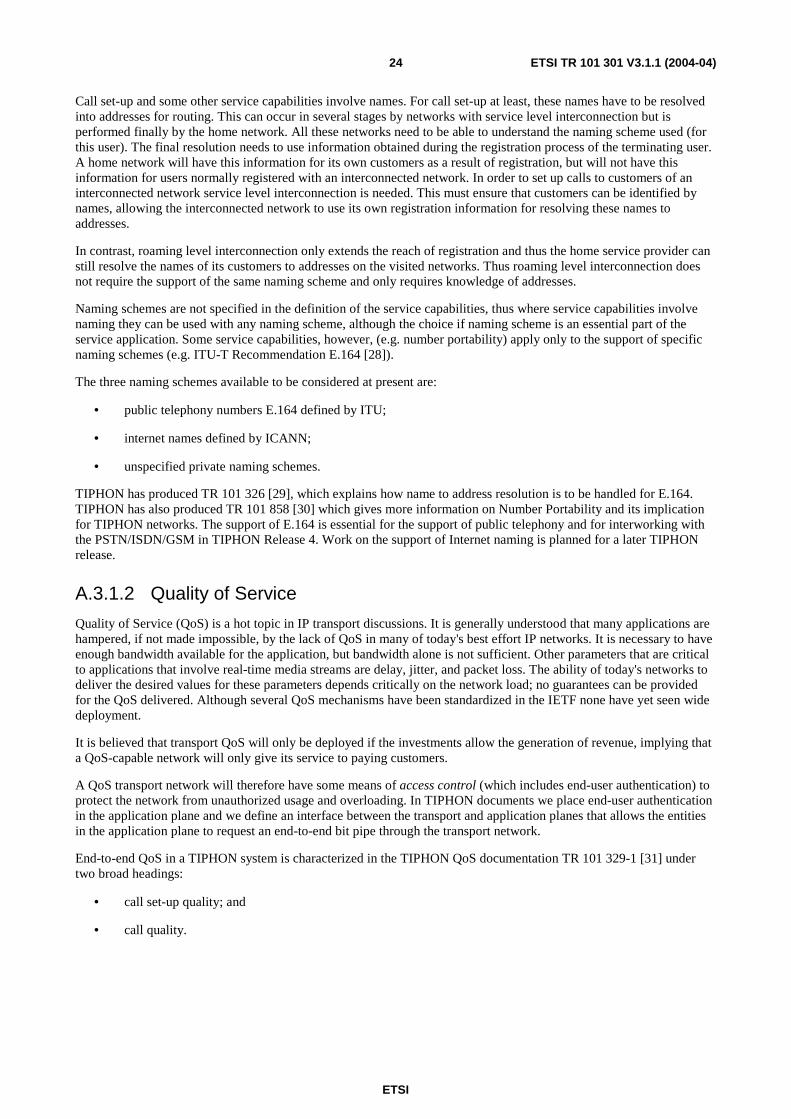
A.3.1.2 Quality of Service
Quality of Service (QoS) is a hot topic in IP transport discussions. It is generally understood that many applications are hampered, if not made impossible, by the lack of QoS in many of today's best effort IP networks. It is necessary to have enough bandwidth available for the application, but bandwidth alone is not sufficient. Other parameters that are critical to applications that involve real-time media streams are delay, jitter, and packet loss. The ability of today's networks to deliver the desired values for these parameters depends critically on the network load; no guarantees can be provided for the QoS delivered. Although several QoS mechanisms have been standardized in the IETF none have yet seen wide deployment.
It is believed that transport QoS will only be deployed if the investments allow the generation of revenue, implying that a QoS-capable network will only give its service to paying customers.
A QoS transport network will therefore have some means of access control (which includes end-user authentication) to protect the network from unauthorized usage and overloading. In TIPHON documents we place end-user authentication in the application plane and we define an interface between the transport and application planes that allows the entities in the application plane to request an end-to-end bit pipe through the transport network.
End-to-end QoS in a TIPHON system is characterized in the TIPHON QoS documentation TR 101 329-1 [31] under two broad headings:
• call set-up quality; and
• call quality.

ETSI
ETSI TR 101 301 V3.1.1 (2004-04) 25
Call set-up quality is mainly characterized by the call set-up time which is perceived by the user as the responsiveness of the service. Call set-up time is the time elapsed from the end of the user interface command by the caller (keypad dialling, E-mail alias typing, etc.) to the receipt by the caller of meaningful progress information. TIPHON QoS documents provide the exact definition of the various call set-up times for use in TIPHON systems, whereas ITU-T Recommendation E.600 [32] provides more information on the definition of post-dialling delay in SCN systems. Call quality is characterized by the overall transmission quality rating R which describes the full acoustic-to-acoustic (mouth to ear) quality, experienced by a user, for a typical situation using a "standard" telephony handset. The overall transmission quality rating is calculated using the E-Model described in ITU-T Recommendation G.107 [33]. For calculation purposes the use of traditional telephone handsets at both sides of the connection is assumed as described in ITU-T Recommendation P.310 [34].
Within the overall transmission quality two major factors contribute to the overall QoS experience of the user of the TIPHON system:
• end-to-end delay: this mainly impacts the interactivity of a conversation. The measurement is done from the mouth of the speaker to the ear of the listener; and
• end-to-end speech quality: this is the one-way speech quality as perceived in a non-interactive situation.
The measurement methodologies for these parameters are specified in TS 101 329-5 [35], while the requirements for these parameters with respect to the various TIPHON QoS classes are defined in TS 101 329-2 [36]. TR 101 329-7 [37] provides guidance on these parameters with respect to the practical design phase of equipment and networks and TS 101 329-3 [38] describes the signalling and control of end-to-end Quality of Service in TIPHON Systems.
A.3.1.3 Security
Transport security is a relatively new concept in telecommunications networks. Like QoS it was taken for granted in the traditional SCN. End-to-end one would like to achieve a private, uninterrupted and authenticated communication. By assuming that the lines of communication in the PSTN cannot be tapped one can assume that the phone network provided this.
The Internet was designed for end-to-end transparency implying that the network behaviour is independent of distance and that addresses are globally routable and independent of location. The whole world looks like a big local area network to a terminal on the Internet. This model works well for a generic packet service since the network itself only transports packets and does not get involved in the content. This transparency has benefited the growth of the Internet allowing the rapid deployment of new services.
On packet networks one does not make these assumptions because in the most common form of packet network (IP over Ethernet), everyone broadcasts their messages assuming the intended recipient will see it. Several techniques have been devised to achieve the goal of private and authenticated communication. Communication can be signed and encrypted in several ways: at the IP level IPsec can be used [39], on the transport level Transport Layer Security (TLS) can be used [40] and in the application. See ITU-T Recommendation H.235 [41] for an overview of security methods. Public peer-to-peer communications is an open invitation for hackers to try and disable servers and users terminals. Consequently, users who access to the internet can expect to be monitored from well beyond their immediate network connection.
ETSI
ETSI TR 101 301 V3.1.1 (2004-04) 26
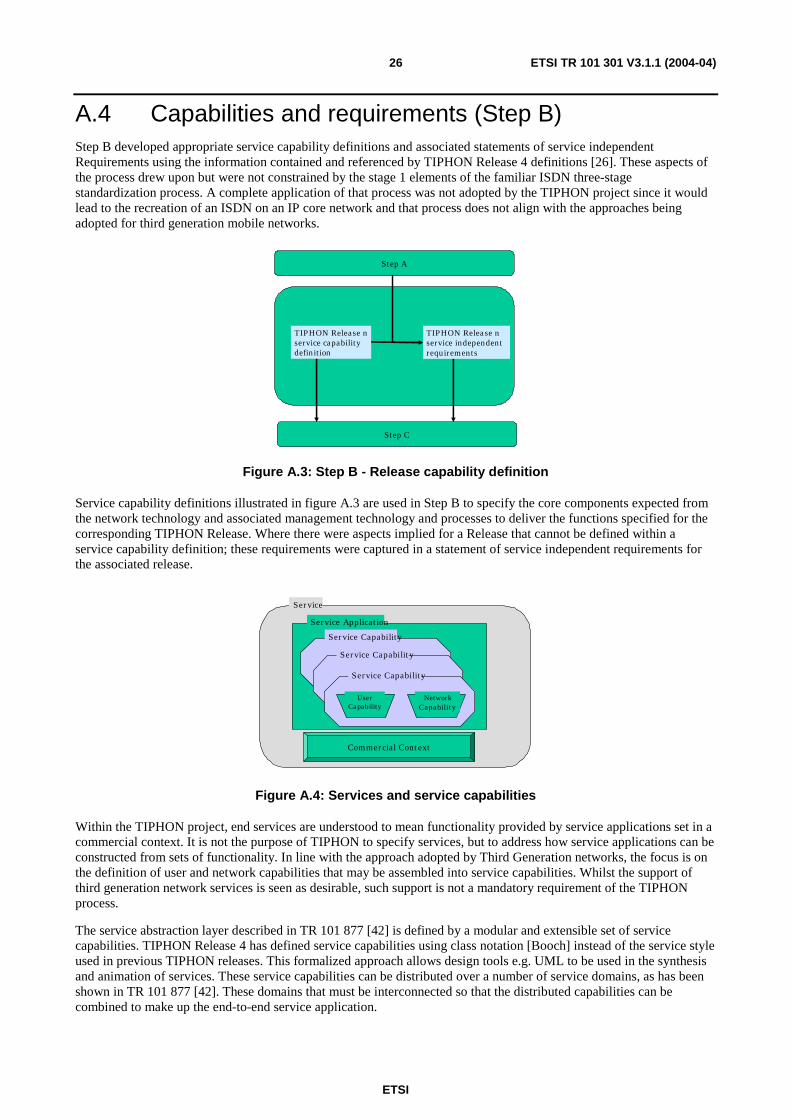
A.4 Capabilities and requirements (Step B) Step B developed appropriate service capability definitions and associated statements of service independent Requirements using the information contained and referenced by TIPHON Release 4 definitions [26]. These aspects of the process drew upon but were not constrained by the stage 1 elements of the familiar ISDN three-stage standardization process. A complete application of that process was not adopted by the TIPHON project since it would lead to the recreation of an ISDN on an IP core network and that process does not align with the approaches being adopted for third generation mobile networks.
Step C
Step A
TIPHON Release nservice capability definition
TIPHON Release nservice independentrequirements
Figure A.3: Step B - Release capability definition
Service capability definitions illustrated in figure A.3 are used in Step B to specify the core components expected from the network technology and associated management technology and processes to deliver the functions specified for the corresponding TIPHON Release. Where there were aspects implied for a Release that cannot be defined within a service capability definition; these requirements were captured in a statement of service independent requirements for the associated release.
Service
Service Capability
Service Capability
Service Capability
NetworkCapability
Commercial Context
Service Application
UserCapability
Figure A.4: Services and service capabilities
Within the TIPHON project, end services are understood to mean functionality provided by service applications set in a commercial context. It is not the purpose of TIPHON to specify services, but to address how service applications can be constructed from sets of functionality. In line with the approach adopted by Third Generation networks, the focus is on the definition of user and network capabilities that may be assembled into service capabilities. Whilst the support of third generation network services is seen as desirable, such support is not a mandatory requirement of the TIPHON process.
The service abstraction layer described in TR 101 877 [42] is defined by a modular and extensible set of service capabilities. TIPHON Release 4 has defined service capabilities using class notation [Booch] instead of the service style used in previous TIPHON releases. This formalized approach allows design tools e.g. UML to be used in the synthesis and animation of services. These service capabilities can be distributed over a number of service domains, as has been shown in TR 101 877 [42]. These domains that must be interconnected so that the distributed capabilities can be combined to make up the end-to-end service application.

ETSI
ETSI TR 101 301 V3.1.1 (2004-04) 27
TIPHON structures concerns using the concepts of domains and functional groups and the following clauses introduce a number of concepts necessary to define service capabilities in the context of domains and their interconnection.
A.4.1 Domains A domain is defined as a collection of physical or functional entities which share a consistent set of policies and common technologies. This concept of domain was the basis for TIPHON protocol harmonization. A domain exposes a consistent set of interfaces to other domains in an appropriate technology. An implementation of this domain with equipment may expose one set of technologies (i.e. protocols) to one domain and another set of technologies to another.
An administrative domain is defined as a collection of physical or functional entities under the control of a single administration. This is a business concept and only of relevance in TIPHON to scope further definitions.
In TIPHON systems three kinds of domains are identified and defined as:
• End-user domain: A collection of physical or functional entities under the control of an end-user, which share a consistent set of policies and common technologies.
• Service domain: A collection of physical or functional entities offering IP telephony services under the control of an IP Telephony Service Provider (ITSP) which share a consistent set of policies and common technologies.
• Transport Domain: A collection of transport resources sharing a common set of policies, QoS mechanisms and transport technologies under the control of a Transport Network Operator (TNO).
The technology within each domain provides a number of functions. It is the behaviour of those functions, which is described by Service Capabilities.
A.4.2 Functional groups TIPHON groups functions that often occur together in functional groups which are collections of functional entities within a domain. In TIPHON, system functional groups are used to structure the necessary functionality to offer IP telephony services across domains. The TIPHON Release 4 architecture [25] defines reference points that describe the communication between the functional entities between and within these functional groups.
Each Domain may contain one or more functional groups. Since a domain is always is part of one administrative domain, it is implicit in this hierarchy that a functional group has only one "owner". It is the "owner" who sets the policy that is applied to technology to create a domain. The owner also decides which service capabilities shall be provided by each functional group.
Functional groups have notions of both ownership and of place in the topology of a call. This means that there is a difference between the originator and the terminator and the roles of intermediate functional groups. In order to specify service capabilities the behaviour is described in terms of ownership and topology but independent of the technology so functional groups are used rather than domains for this purpose.
Functional groups that are used to connect calls from one terminal to another are called network functional groups. In some instances a network functional group will be used to originate calls and at other times to terminate them. The behaviour required will depend on the location of the network functional group in the call topology.
For calls involving two parties there will be an originating network functional group and a terminating network functional group. It may occur that the originating and terminating network functional groups are in the same domain, or even in the same set of equipment, but the general case is still used for specification purposes.
The behaviour of a functional group is determined by whether it is aware of the service application and hence the context in which the service capabilities are being used.
A.4.3 Introduction to the TIPHON transport plane The TIPHON environment addresses the case where multiple networks, possibly employing differing network technologies, interwork to provide end-to-end communications services as shown in figure A.5. This model supports the different business roles found within the heterogeneous communications environment envisaged by TIPHON described in TR 101 877 [42] and commonly found in modern public communications networks.

ETSI
ETSI TR 101 301 V3.1.1 (2004-04) 28
Network Abstraction Layer
Transport Abstraction Layer
Service Abstraction Layer
Terminal Domain #1
Terminal Domain #2
Access Domain#1
Transit Domain#1
Access Domain#2
Transit Domain#2
Service Application Layer
TIPHON Application Plane
TIPHON Transport Plane
Transport Plane/Application Plane Interface
Figure A.5: The TIPHON network and service environment model
The TIPHON network and service environment model is separated into two planes that exist across the various network domains encountered in the end-to-end communications path. These two planes connect with a Management Plane, shown in figure A.6, which exists outside of the TIPHON network and service environment.
Man
agem
ent P
lane
Transport plane
Transport Plane
SCN Plane
Application Plane
Figure A.6: TIPHON planes
As shown, the upper plane comprises the service application and service abstraction layers and is termed the TIPHON application plane. This plane addresses the implementation of end-to-end communications applications. The lower plane includes the transport and network abstraction layers and is termed the TIPHON transport plane. The TIPHON transport plane provides domain independent communications capabilities to the TIPHON application plane. Requirements placed upon the TIPHON transport plane by the TIPHON application plane are expressed in service independent requirements documents in accordance with the TIPHON project method described in TR 101 835 [1].
TR 101 311 [43] describes sets of service independent requirements that specify the required behaviour of the TIPHON transport plane. The TIPHON application plane is expressed in terms of service applications and service capabilities.
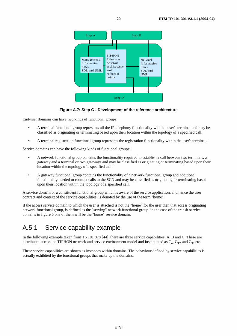
A.5 Reference architecture (Step C) The outputs from both Step A and Step B form the source documents for Step C that develops a reference architecture in support of the release. The reference architecture shall be developed independently of underlying technology issues where possible and represents a static design for the release. In support of the reference architecture, management and network information flows are developed to express the dynamic behaviour of the system.
ETSI
ETSI TR 101 301 V3.1.1 (2004-04) 29
Step D
Step BStep A
TIPHON Release n Abstractarchitectureand referencepoints
NetworkInformationflows, SDL and UML
ManagementInformationflows, SDL and UML
Figure A.7: Step C - Development of the reference architecture
End-user domains can have two kinds of functional groups:
• A terminal functional group represents all the IP telephony functionality within a user's terminal and may be classified as originating or terminating based upon their location within the topology of a specified call.
• A terminal registration functional group represents the registration functionality within the user's terminal.
Service domains can have the following kinds of functional groups:
• A network functional group contains the functionality required to establish a call between two terminals, a gateway and a terminal or two gateways and may be classified as originating or terminating based upon their location within the topology of a specified call.
• A gateway functional group contains the functionality of a network functional group and additional functionality needed to connect calls to the SCN and may be classified as originating or terminating based upon their location within the topology of a specified call.
A service domain or a constituent functional group which is aware of the service application, and hence the user contract and context of the service capabilities, is denoted by the use of the term "home".
If the access service domain to which the user is attached is not the "home" for the user then that access originating network functional group, is defined as the "serving" network functional group. in the case of the transit service domains in figure 6 one of them will be the "home" service domain.
A.5.1 Service capability example In the following example taken from TS 101 878 [44], there are three service capabilities, A, B and C. These are distributed across the TIPHON network and service environment model and instantiated as Co, CT2 and CT, etc.
These service capabilities are shown as instances within domains. The behaviour defined by service capabilities is actually exhibited by the functional groups that make up the domains.

ETSI
ETSI TR 101 301 V3.1.1 (2004-04) 30
Access Service Domain
Transit Service
Domain #2
End-Usert Domain
End-Usero Domain
Access Service Domain
Ao
Bo
Co
At
Bt
Ct
Atr
Ctr
Btr Bao
Aao
Bat
Aat
Figure A.8: Service capabilities interworking across domains
In figure A.8, the behaviour of the service capabilities A, B and C are defined. Service capabilities A and B behaviours are shown in each of the domains. Service capability C is shown as having no behaviour other than message conveyance within the access service domains but behaviour is defined (Ctr) in the end-user and transit service domains.
A.5.2 User roaming considerations In the TIPHON approach, each service provider creates their own service offering. This service offering will consists of any number of service applications possibly bound by one user Name.
In deployments where a user may roam on other networks, the visited network may not understand the particulars of service application that users wish to use and may even not understand the naming scheme used, and in this case all signalling will have to pass through the home network. Visited domains will only relay signalling to and from the appropriate (home) domain and (possibly) creation of bearers.
For some service applications such as public telephony, it may be necessary for visited networks to support some additional functionality such as emergency calls because this essential service needs to be provided locally since it requires access to local information and/or local points of connection.
The network functional group represents all of the functionality of an IP-based application in support of the call. In environments where users roaming does not take place the originating end-user always has a contract with the IP telephony service provider controlling the service domain containing the originating network functional group and the terminating user with the IP telephony service provider controlling the service domain containing the terminating network functional group.
The network functional group which acts as the "home" for the originating user is the originating home network functional group. Whilst the registration function is related to the functional groups described as "home", it need not be co-located with it or part of it.
For user roaming considerations this may not be the case. Therefore network functional groups are further divided into serving network, intermediate and home network functional groups where these are defined:
• Serving network functional group enables terminal functional groups to connect to a service IP telephony service provider and represents the functions required to enable the user to register and to use services provided by the home network functional group.
• Intermediate (transit) functional group connects the serving network functional group to the home network functional group. (The intermediate network functional group is only present when the serving network functional group and the home network functional group are not directly connected.)

ETSI
ETSI TR 101 301 V3.1.1 (2004-04) 31
• Home network functional group is aware of the service application subscribed to by the end-user. Home network functional groups may be classified as originating or terminating based upon their location within the topology of a specified call.
The home network functional group and the serving network functional group may reside in the same service domains or different service domains. It was not assumed that signalling and media follow the same path through packet switching systems.
Serving network
functional grouping
Terminal registration functional grouping
Home network
functional grouping
Intermediate network
functional grouping
Figure A.9: Overview of functional groups involved in registration
Figure A.9 shows the functional groups involved with the registration process:
• The terminal registration functional group represents the functionality of the registering terminal.
• The serving network functional group represents the functions required to enable the user to register and to use services provided by the home network functional group.
• The intermediate functional group connects the serving network functional group to the home network functional group.
• The home network functional group represents functionality relating to the user's profile and subscription.
A.5.3 TIPHON Scenario 0 functional groups Scenario 0 is the all-IP scenario whereby all functional groups are on the IP network. Figure A.10 shows the possible functional groups involved in a Scenario 0 call.
Originating
network FG
Transit
FG
Terminating
network FG
Terminating
terminal
FG
Originating
terminal
FG
Figure A.10: TIPHON Scenario 0 without users roaming
Figure A.10 shows symmetry about the Intermediate (transit) functional group at the centre of each reference configuration. This may be the typical scenario. The minimum extreme case is where the originating and terminating network function groups are the same, in that case there is no intermediate network functional group. A maximum extreme case there is multiple intermediate network functional groups.
The cases of one or both of the users is roaming is elaborated by adding the relevant roaming users part to the diagram in figure A.11. The actors in terms of domains which have differing behaviour are depicted for the extreme case by the following functional groups:
Originating
Terminal FG
Transit
FG
Terminating
Terminal FG FG
Origi- nating Home
FG
Serving
FG
Termi- nating Home
FG
Transit
FG
Transit
FG
Serving
FG
Figure A.11: TIPHON Scenario 0 with both users roaming

ETSI
ETSI TR 101 301 V3.1.1 (2004-04) 32
A.5.4 TIPHON Scenario 1 functional groups Scenario 1 differs from Scenario 0 because the terminating side functions are handled in the SCN behind a gateway network functional group. From the point of service capabilities the domain containing the gateway exhibits all of the service capabilities associated with the called party. The list of the actors for Scenario 1, in terms of domains which have differing behaviour are depicted by the following functional groups:
Origi- nating
Terminal
FG
Originating
Network Transit
FG
Termi-nating
Gateway
FG FG
Figure A.12: TIPHON Scenario 1 - simple case
Origi-nating
Terminal FG
Transit
FG
Terminating Gateway
FG
Origi-nating
Home FG
Serving
FG
Transit
FG
Figure A.13: TIPHON Scenario 1 - originating user roaming
A.5.5 TIPHON Scenario 2 functional groups Scenario 2 differs from Scenario 0 because the functions on the Originating side are handled inside the originating gateway. From the point of service capabilities, the domain containing the gateway exhibits all of the service capabilities associated with the calling party. The list of the actors for Scenario 2, in terms of domains which have differing behaviour are depicted by the following functional groups:
Origi-nating
Gateway FG
Transit FG
Termi-nating Network
Termi-nating
Terminal FG FG
Figure A.14: TIPHON Scenario 2 - simple case
Origi-nating
Gateway FG
Transit FG
Termi-nating
Terminal FG
Termi-nating Network
FG
Transit FG
Serving FG
Figure A.15: TIPHON Scenario 2 - terminating user roaming
A.5.6 TIPHON Scenario 3 functional groups Scenario 3 bypasses SCN long distance via an IP network. The simple form occurs when neither user has a service instance in a TIPHON network. The complex case is similar to Scenario 2 but the call is diverted to another network via a gateway. The list of the actors for Scenario 3, in terms of domains which have differing behaviour are depicted by the following functional groups:

ETSI
ETSI TR 101 301 V3.1.1 (2004-04) 33
Originating Gateway
FG
Transit FG
Terminating Gateway
FG
Figure A.16: TIPHON Scenario 3 - simple case
Originating Gateway
FG
Transit FG
Terminating Gateway
FG
Termi-nating Home
FG Transit
FG
Figure A.17: TIPHON Scenario 3 - terminating user roaming
A.6 Implementation framework (Step D) For a given TIPHON Release, the reference architecture and associated network and management information flows will be mapped into individual protocol and management frameworks, as indicated in figure A.18. The frameworks identify key interfaces and establish requirements for information flows over each interface. These frameworks are the essential means by which the TIPHON project remains protocol neutral to the last point in specification development - ensuring that the complex interworking issues addressed by the project can be fully explored independently of technology constraints. Once the interface requirements have been produced, they are then mapped into a given technology through technology mapping and compliance definitions.
Step E
Step BStep A Step C
TIPHON Release nProtocol FrameworkDefinition
TIPHON Release nManagementFrameworkDefinition
TIPHON Release nInterface ProtocolRequirementsDefinitions
TIPHON Release nManagementInterfaceRequirementsDefinitions
Figure A.18: Step D implementation framework

ETSI
ETSI TR 101 301 V3.1.1 (2004-04) 34
TS 101 882 [24] defines the framework for protocols to fit into in order to be considered as compliant to TIPHON. Information flows and reference points for application of the TIPHON functional architecture for inter-domain services are described in TS 101 315 [45]. The requirements for the protocol framework are described in the TIPHON abstract architecture TS 101 314 [25] and are required to implement the capabilities described in TS 101 878 [44]. The framework is written in the form of a set of meta-protocols described both in syntax using Abstract Syntax Notation 1 (ASN1) [46] and in behaviour using Message Sequence Charts (MSC) [46] and simple Specification and Description Language (SDL) diagrams [46]. The meta-protocols show both the service primitives used by higher or lower layers to invoke, control and report on the progress of the meta-protocol, and the meta protocol message units used to communicate with peer entities.
Meta-protocols are described in TS 101 882 [24] for the following reference points defined in TS 101 314 [25]: S, N, C, T, R and M applicable to the protocols implemented by equipment fulfilling the roles that are necessary to support TIPHON Release 4.
The meta protocol message units map to Protocol Data Units (PDUs) or equivalent message types in candidate protocols. The service primitives map to either Application Programming Interface (API) calls or to protocol primitives in candidate protocols. Interoperability of candidate protocols to the outlined meta-protocols can be achieved by converting the native syntax of the candidate protocol to ASN.1 and by describing the relationship between the native behaviour of the candidate protocol and the behaviour described for each meta-protocol.
A service interaction diagram of the TIPHON planes as defined in TS 101 314 [25] is given in figure A.19. The planes and the functional entities they contain communicate across a set of Service Access Points (SAPs) for each of TIPHON Call Control (TCC), TIPHON Registration (TR), TIPHON Transport (TT), and TIPHON Lower Layers (TLL). Above the TCC-SAP and TR-SAP is the user or service plane that may invoke functions and features in the application plane in a number of ways thereby defining user services. TS 101 882 [24] specifies the primitives and Meta Protocol Message Units for the registration and call control functions in the application plane, and provides a description of the transport plane primitives and behaviour.
The intention of the meta-protocol design description is to be independent of network technology. The terminology used throughout is deliberately abstract; functional entities are numbered, with an indication of the probable functional grouping to which they belong. This method of description allows for open mapping to the functionality of the entity and places no restrictions on the application of any functional entity to alternative functional groupings.

ETSI
ETSI TR 101 301 V3.1.1 (2004-04) 35
Transport plane
TT-SAP
Application plane
Call Control Registration
TCC-SAP TR-SAP
TLL-SAP
TCC-SAP: TIPHON Call Control Service Access Point TR-SAP: TIPHON Registration Service Access Point TT-SAP: TIPHON Transport Service Access Point TLL-SAP: TIPHON Lower Layer Service Access Point
Figure A.19: The TIPHON inter-planar service interfaces
The TT-SAP enables the transport of both QoS optimized media types and non-QoS optimized signalling and media types. Examples of QoS optimized media transport include: speech; and, broadcast video. Examples of non-QoS optimized media transfer include: file transfer, e-mail and signalling.
The SAPs carry service primitives in the manner shown in figure A.20.
Protocol/Functional Entity
Protocol Transport
Request
Confirm Primitives at SAP
Function A Function B
Protocol Entity
Response
Indication Primitives at SAP
Protocol Entity
Protocol/Functional Entity
Figure A.20: Relationship of functional entities, primitives and protocols
The entities involved in peer-to-peer relationships may be located in networks that are under the same or different Administrative control. For the purposes of testing and verification the meta-protocols shall be considered as visible at application specific reference points as described in TS 101 314 [25]. Candidate protocols may map, as appropriate, many of the meta-protocols relevant to application specific reference points described in TS 101 314 [25] to candidate protocols relevant to a single reference points in their native environment.

ETSI
ETSI TR 101 301 V3.1.1 (2004-04) 36
The data transfer within a single physical entity, represented as primitives between functional entities, may not be visible externally and may therefore not be explicitly testable or capable of being mapped by candidate protocols.
For the network technology elements, the protocol framework is developed to provide an identification of the key interfaces required in a system that is compliant with the specific TIPHON release. For each interface identified, detailed requirements state the behaviour that is to be provided across the interface.
A.6.1 Basic call example In this clause, the general model outlined in the previous clause is applied. It shows how the model may be used and applied in real-world situations. It starts with providing a general model of the states in a telephone call, loosely based on the ITU-T Recommendation Q.931 [47] and Intelligence Network (IN) call state models. Next, this is extended for supplementary services and multi-domain services to show how robust the model is and how it can be refined to provide these services.
The basic telephone call consists of a number of activities that have to occur before the call can be set up:
1) The call is initiated.
2) The call is authorized by the service provider.
3) The call is routed towards the destination.
4) Call associated bearers are set up.
5) Media flows are established for the bearers.
6) Appropriate transport is arranged for the media flows.
7) The call and bearer requests are forwarded to the next domain (or terminal).
8) The call is accepted by the recipient.
9) The media flows.
10) The call is torn down, and along with it the bearers, media and transport are torn down.
Figure A.21 shows these steps in a schematic way. These 10 steps are usually taken in this order to retain the feel of the realization in the SCN. If this sequence is not followed, the perceived post-set-up delay (i.e. the time from receiver pick-up to media establishment) would be very large or the first few seconds of speech may be choppy because the speech is sent "best-effort".
The routing request flow performed in step 3 allows any intelligent routing mechanism including number portability and intelligent routing schemes to be hidden.
Note that the bearer is set up in three phases:
a) in the fist phase the originator offers his capabilities for sending and receiving and commits to receive what was offered;
b) in the second phase the remote side has answered and offered its capabilities and the appropriate reverse stream can be prepared;
c) in the third phase the (reverse) speech channel is opened when the call has been accepted.
The service provider can enforce the access policy in the third phase.
Using the information flows down to the transport plane and up to the service control we can implement strict access and usage control in both the transport plane (it can block any non-authorized streams) and in the application plane (it can try and authorize users before committing resources).

ETSI
ETSI TR 101 301 V3.1.1 (2004-04) 37
Domain 1
CC
BC
SC
MC
SE
Domain 2
SC
CC
BC
MC
SE
Domain 3
CC
BC
SC
MC
SE
ServiceControl
CallControl
MediaControl
BearerControl
Services
Packet transport
1 2
2 3
3
4
5
6
4
7
8 10
7
9
Figure A.21: Schematic call set-up diagram
A.7 Technology mapping and verification (Step E) The completed interface definitions were mapped into the technologies supported by release 4 of the TIPHON project. This was achieved by providing an appropriate profile of the technology for a given interface, as shown in figure A.22. Where a technology fully meets the requirements for a specific interface, a protocol profile will be produced for that protocol which defines its use in implementing that interface. However where a specific technology does not support the required functionality, the mapping will not be able to generate a profile - as shown in the case of Technology A in figure A.22 for interface "q". For such cases, the requirements identified for the interface may be used as the basis of extensions to the technology in question.
TIPHONRelease ninterfaceprotocolRequirement q
TIPHONRelease ninterfaceprotocolRequirement k
TIPHONRelease ninterfaceprotocolRequirement z
TIPHONRelease nprotocolframework
Technologymapping andcompliance(Technology B)
Technologymapping andcompliance(Technology A)
Figure A.22: Step E - Network technology mapping
In a similar manner, the management framework is developed and mapped via management interfaces onto supporting technologies as shown in figure A.23. As with the network technology framework, the process of mapping will expose any deficiencies in the underlying technology. In the example shown, Technology A is found to meet the requirements for management interfaces "k" and "z" but does not meet the requirements for interface "q". This contrasts with
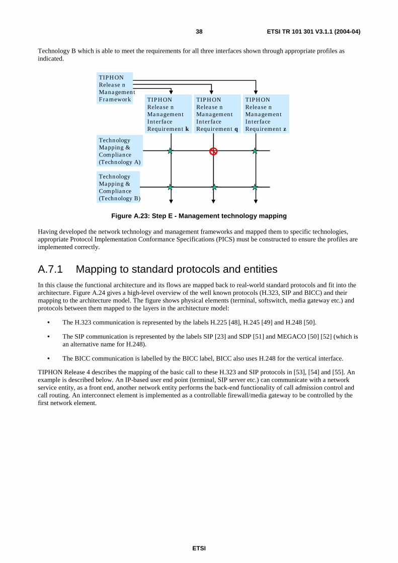
ETSI
ETSI TR 101 301 V3.1.1 (2004-04) 38
Technology B which is able to meet the requirements for all three interfaces shown through appropriate profiles as indicated.
TIPHONRelease nManagementInterfaceRequirement q
TIPHONRelease nManagementInterfaceRequirement k
TIPHONRelease nManagementInterfaceRequirement z
TIPHONRelease nManagementFramework
TechnologyMapping &Compliance(Technology B)
TechnologyMapping &Compliance(Technology A)
Figure A.23: Step E - Management technology mapping
Having developed the network technology and management frameworks and mapped them to specific technologies, appropriate Protocol Implementation Conformance Specifications (PICS) must be constructed to ensure the profiles are implemented correctly.
A.7.1 Mapping to standard protocols and entities In this clause the functional architecture and its flows are mapped back to real-world standard protocols and fit into the architecture. Figure A.24 gives a high-level overview of the well known protocols (H.323, SIP and BICC) and their mapping to the architecture model. The figure shows physical elements (terminal, softswitch, media gateway etc.) and protocols between them mapped to the layers in the architecture model:
• The H.323 communication is represented by the labels H.225 [48], H.245 [49] and H.248 [50].
• The SIP communication is represented by the labels SIP [23] and SDP [51] and MEGACO [50] [52] (which is an alternative name for H.248).
• The BICC communication is labelled by the BICC label, BICC also uses H.248 for the vertical interface.
TIPHON Release 4 describes the mapping of the basic call to these H.323 and SIP protocols in [53], [54] and [55]. An example is described below. An IP-based user end point (terminal, SIP server etc.) can communicate with a network service entity, as a front end, another network entity performs the back-end functionality of call admission control and call routing. An interconnect element is implemented as a controllable firewall/media gateway to be controlled by the first network element.

ETSI
ETSI TR 101 301 V3.1.1 (2004-04) 39
MG control SC
CC
MGW
BC
MC
SC
CC
SE
BC
CC
SC
SE
BC
MC
Terminal/ SIP client
SC
CC
SE
BC
Gatekeehper SIP Server/ SoftSwitch
MD
Gatekeeper/ SIP Server/ SoftSwitch
RTP
H.225 (RAS) SIP
H.225 (Q.931) SIP
H.245 SDP
RTP
Sig-GW SC
CC
H.225 (RAS)
H.225 Ann G
H.225.0 (Q.931) SIP, BICC
H.245 SDP
H.248/MEGACO
H.225 (RAS)
H.225 Ann G
H.225.0 (Q.931) SIP, BICC
H.245 SDP
ISUP/Q.931
INAP
Gateway Media
Control
BearerControl
CallControl
ServiceControl
Services
MC
Packet Transport Plane
H.248/MEGACO
PSTN
Figure A.24: Mapping to physical entities and protocols
Step BStep A Step D
TIPHON Release nSecurity Analysisand ComplianceSpecification
TIPHON Release nProtocolImplementationConformanceSpecification
TIPHON Release nTechnology (A)Mapping andCompliance
Figure A.25: Step E - Conformance specifications and security analysis
The final element of Step E completes the security analysis and compliance specification, and acts as a final check on the release to ensure security and integrity issues have been correctly addressed [57], [58] and [59].
Figure A.26 provides an insight into the testing methodology and associated documentation.
Figure A.26: Testing methodology and associated documentation

ETSI
ETSI TR 101 301 V3.1.1 (2004-04) 40
The Implementation Conformance Statement (ICS) is a checklist of the capabilities supported by the Implementation Under Test (IUT). It provides an overview of the features and options that are implemented. The ICS can be used to select and parameterize test cases and as an indicator for basic interoperability between different products. See EG 201 058 [60] ICS proforma style guide.
The Test Suite Structure and Test Purposes (TSS&TP) are derived from the relevant base standards. They provide an informal, easy-to-read description of each test, concentrating on the meaning of the test rather than detailing how it may be achieved. Test Purposes are grouped into a logical Test Suite Structure according to suitable criteria (e.g. basic interconnection, error handling, functionality etc.) (see ETR 266 [61] Test Purpose style guide).
The Abstract Test Suite (ATS) is the entire collection of Test Cases. Each Test Case specifies the detailed coding of the Test Purposes, written in the standardized test specification language TTCN. See EG 202 103 [62] Guide for the use of TTCN-2 and ETR 141 [63] TTCN style guide.
The Implementation eXtra Information for Testing (IXIT) contains additional information (e.g. specific addresses, timer values etc.) necessary for testing.
The Executable Test Suite (ETS) can be quickly and easily implemented from the ATS using the TTCN compilers available on most modern test tool platforms.

ETSI
ETSI TR 101 301 V3.1.1 (2004-04) 41
Annex B: Bibliography
• DTS/TISPAN-06006-01-TIPHON_R4: "Telecommunications and Internet Protocol Harmonization Over Networks (TIPHON) Release 4; Technology Compliance Specification; TIPHON profile for Open Settlement Protocol (OSP); Part 1: Protocol Implementation Conformance Statement (PICS) Proforma".
• DTS/TISPAN-06006-02-TIPHON_R4: "Telecommunications and Internet Protocol Harmonization Over Networks (TIPHON) Release 4; Technology Compliance Specification; TIPHON profile for Open Settlement Protocol (OSP); Part 2: Test Suite Structure (TSS) and Test Purposes (TP)".
• DTS/TISPAN-06006-03-TIPHON_R4: "Telecommunications and Internet Protocol Harmonization Over Networks (TIPHON) Release 4; Technology Compliance Specification; TIPHON profile for Open Settlement Protocol (OSP); Part 3: Abstract Test Suite (ATS) and PIXIT Proforma".

ETSI
ETSI TR 101 301 V3.1.1 (2004-04) 42
History
Document history
V1.1.1 March 2001 Publication (Historical)
V2.1.1 February 2002 Publication
V3.1.1 April 2004 Publication


![TS 132 015 - V3.1.1 - Digital cellular telecommunications system (Ph&|!ÜGBB-] ×n… · 2000-05-16 · ETSI 3G TS 32.015 version 3.1.1 Release 1999 8 ETSI TS 132 015 V3.1.1 (2000-03)](https://static.documents.pub/doc/80x56/5e8b7fbf62436545c12837ef/ts-132-015-v311-digital-cellular-telecommunications-system-phoegbb-.jpg)


