2332-7782 (c) 2021 IEEE. Personal use is permitted, but republication/redistribution requires IEEE permission. See http://www.ieee.org/publications_standards/publications/rights/index.html for more information. This article has been accepted for publication in a future issue of this journal, but has not been fully edited. Content may change prior to final publication. Citation information: DOI 10.1109/TTE.2021.3075844, IEEE Transactions on Transportation Electrification >TTE-Reg-2020-12-1260.R2 < 1 Abstract— More efficient cooling systems are an enabler for the increase in power-density in an electric traction motor. Contemplating to existing reviews, this paper presents a comprehensive collection of heat transfer mechanisms for the different heat removal techniques used in electric traction motors. In the first section, an overview of various cooling concepts in existing and future traction motors is presented and the cooling approaches are compared. The following literature review compiles geometry-based calculation formulas of the different mechanisms of cooling heat transfer applied in motor-technology. Furthermore general heat transfer phenomena appearing in electric traction motors are reviewed and compiled for easy access. Various specifically relevant aspects, including rotor shaft cooling, different spray cooling concepts, different air convection phenomena, bearing heat transfer and the stator-housing-contact, are examined in more detail. For validation of the review result, based on a well-known motor design a thermal analysis and comparison of the different cooling methods is carried out. Modeling is done with a lumped parameter thermal networks (LPTN). The paper concludes demonstrating the advantages and disadvantages of the different cooling concepts based on the collection of modeling data. Index Terms— Cooling, Traction motor drives, Review, Electric machines, Road vehicles I. INTRODUCTION HE shift towards sustainable mobility is driving the development of new electric vehicle traction motor drives. In early development stages of new electric drives many geometry variations need to be simulated and tested to reach the target specifications in efficiency and power [1]. With increasing power density in electric traction motors even more efficient cooling systems for removing the electric and thermal power losses are needed. Main reasons for cooling the motor components are slowing the insulation aging and keeping the magnetic material in permanent-magnet machines below their demagnetization temperature with a certain safety-margin for avoiding drops in torque and power over the motor life time [2 4]. However secondary thermal limits become relevant, such as limitations of power electronic components and lubricants, the wish to limit the resistance increase in the conductors and delamination-risk of stacked metal sheets. Due to the nature of geometry at radial-flux machines, especially an effective cooling of the rotor is on focus for high-speed traction motor Peer-Ole Gronwald (e-mail: [email protected]) is with Volkswagen AG, 38436 Wolfsburg and Institute for Mechatronics (iMEK) at the Hamburg University of Technology, 21073 Hamburg. Thorsten A. Kern (e- applications. Common cooling techniques, such as cooling jackets, have been investigated more intensively than e.g. spray cooling or high-speed rotor shaft cooling [3, 5]. For the potential analysis of new cooling concepts, the heat transfer mechanisms behind the respective concepts must be examined and understood in more detail. In order to specify the optimal solution for new cooling systems, valid information about the heat transfer mechanism and the thermal behavior of the concepts to be tested is required. However even at early design stages, a purely analytical approach is not sufficient anymore to optimize the designs at the current state-of-the-art degree of optimization. Therefor even for early stages of designing and developing new traction motor cooling systems a discrete modelling is required. Lumped parameter thermal networks (LPTNs) have proven to reduce the simulation time compared to computational fluid dynamics (CFD) tools and finite element analysis (FEA) [6, 7]. In order to be able to simulate and calculate various motor geometry varieties, various network configurations are required to describe the heat transfer behavior. This paper shows different models and calculation approaches for the heat transfer behavior in electrical machines and different cooling systems for electric traction motors. The first section presents a market overview and analysis of existing traction motors and their cooling. Afterwards the heat transfer mechanisms of different cooling concepts are explained and overviews of calculation approaches and formulas for the different cooling systems and typical electric motor heat transfer problems are given. In the last section, the concepts presented are validated using a two-dimensional (2D) LPTNs in comparison with each other on the basis of an existing motor design concept. II. OVERVIEW OF TRACTIONS MOTORS IN APPLICATION AND CONCEPT MOTORS The growing market of electric vehicles well reflects the current trend of increasing peak powertrain powers, more complex cooling systems and higher rotational motor speeds in electric traction motors (Table 1).This paper gives an overview of new electric motors and cooling systems, without considering new patents, not mentioned in earlier overview publications (Fig. 1, Table 1) [3, 5, 8, 9]. Based on the gathered information from freely accessible, internal and commercial mail: [email protected]) is head of Institute for Mechatronics (iMEK) at the Hamburg University of Technology. This research did not receive any specific grant from funding agencies in the public, commercial, or not-for-profit sectors. Traction motor cooling systems, a literature review and comparative study Peer-Ole Gronwald and Thorsten A. Kern, Member, IEEE T Authorized licensed use limited to: TU Hamburg-Harburg. Downloaded on April 28,2021 at 06:05:35 UTC from IEEE Xplore. Restrictions apply.
Transcript
2332-7782 (c) 2021 IEEE. Personal use is permitted, but republication/redistribution requires IEEE permission. See http://www.ieee.org/publications_standards/publications/rights/index.html for more information.
This article has been accepted for publication in a future issue of this journal, but has not been fully edited. Content may change prior to final publication. Citation information: DOI 10.1109/TTE.2021.3075844, IEEETransactions on Transportation Electrification
>TTE-Reg-2020-12-1260.R2 <
1
Abstract— More efficient cooling systems are an enabler for the
increase in power-density in an electric traction motor. Contemplating to existing reviews, this paper presents a comprehensive collection of heat transfer mechanisms for the different heat removal techniques used in electric traction motors. In the first section, an overview of various cooling concepts in existing and future traction motors is presented and the cooling approaches are compared. The following literature review compiles geometry-based calculation formulas of the different mechanisms of cooling heat transfer applied in motor-technology. Furthermore general heat transfer phenomena appearing in electric traction motors are reviewed and compiled for easy access. Various specifically relevant aspects, including rotor shaft cooling, different spray cooling concepts, different air convection phenomena, bearing heat transfer and the stator-housing-contact, are examined in more detail. For validation of the review result, based on a well-known motor design a thermal analysis and comparison of the different cooling methods is carried out. Modeling is done with a lumped parameter thermal networks (LPTN). The paper concludes demonstrating the advantages and disadvantages of the different cooling concepts based on the collection of modeling data.
Index Terms— Cooling, Traction motor drives, Review, Electric machines, Road vehicles
I. INTRODUCTION HE shift towards sustainable mobility is driving the development of new electric vehicle traction motor drives.
In early development stages of new electric drives many geometry variations need to be simulated and tested to reach the target specifications in efficiency and power [1]. With increasing power density in electric traction motors even more efficient cooling systems for removing the electric and thermal power losses are needed. Main reasons for cooling the motor components are slowing the insulation aging and keeping the magnetic material in permanent-magnet machines below their demagnetization temperature with a certain safety-margin for avoiding drops in torque and power over the motor life time [2 4]. However secondary thermal limits become relevant, such as limitations of power electronic components and lubricants, the wish to limit the resistance increase in the conductors and delamination-risk of stacked metal sheets. Due to the nature of geometry at radial-flux machines, especially an effective cooling of the rotor is on focus for high-speed traction motor
Peer-Ole Gronwald (e-mail: [email protected]) is with Volkswagen AG, 38436 Wolfsburg and Institute for Mechatronics (iMEK) at the Hamburg University of Technology, 21073 Hamburg. Thorsten A. Kern (e-
applications. Common cooling techniques, such as cooling jackets, have been investigated more intensively than e.g. spray cooling or high-speed rotor shaft cooling [3, 5]. For the potential analysis of new cooling concepts, the heat transfer mechanisms behind the respective concepts must be examined and understood in more detail. In order to specify the optimal solution for new cooling systems, valid information about the heat transfer mechanism and the thermal behavior of the concepts to be tested is required. However even at early design stages, a purely analytical approach is not sufficient anymore to optimize the designs at the current state-of-the-art degree of optimization. Therefor even for early stages of designing and developing new traction motor cooling systems a discrete modelling is required. Lumped parameter thermal networks (LPTNs) have proven to reduce the simulation time compared to computational fluid dynamics (CFD) tools and finite element analysis (FEA) [6, 7]. In order to be able to simulate and calculate various motor geometry varieties, various network configurations are required to describe the heat transfer behavior. This paper shows different models and calculation approaches for the heat transfer behavior in electrical machines and different cooling systems for electric traction motors. The first section presents a market overview and analysis of existing traction motors and their cooling. Afterwards the heat transfer mechanisms of different cooling concepts are explained and overviews of calculation approaches and formulas for the different cooling systems and typical electric motor heat transfer problems are given. In the last section, the concepts presented are validated using a two-dimensional (2D) LPTNs in comparison with each other on the basis of an existing motor design concept.
II. OVERVIEW OF TRACTIONS MOTORS IN APPLICATION AND CONCEPT MOTORS
The growing market of electric vehicles well reflects the current trend of increasing peak powertrain powers, more complex cooling systems and higher rotational motor speeds in electric traction motors (Table 1).This paper gives an overview of new electric motors and cooling systems, without considering new patents, not mentioned in earlier overview publications (Fig. 1, Table 1) [3, 5, 8, 9]. Based on the gathered information from freely accessible, internal and commercial
mail: [email protected]) is head of Institute for Mechatronics (iMEK) at the Hamburg University of Technology. This research did not receive any specific grant from funding agencies in the public, commercial, or not-for-profit sectors.
Traction motor cooling systems, a literature review and comparative study
Peer-Ole Gronwald and Thorsten A. Kern, Member, IEEE
T
Authorized licensed use limited to: TU Hamburg-Harburg. Downloaded on April 28,2021 at 06:05:35 UTC from IEEE Xplore. Restrictions apply.
2332-7782 (c) 2021 IEEE. Personal use is permitted, but republication/redistribution requires IEEE permission. See http://www.ieee.org/publications_standards/publications/rights/index.html for more information.
This article has been accepted for publication in a future issue of this journal, but has not been fully edited. Content may change prior to final publication. Citation information: DOI 10.1109/TTE.2021.3075844, IEEETransactions on Transportation Electrification
>TTE-Reg-2020-12-1260.R2 <
2
sources a comparison of different electric vehicle drives and used cooling systems is shown below (Fig. 2) [21, 22, 45–52].
Fig. 2 Comparison of electric vehicle traction motor cooling concepts
The data show that there are limits for the use of cooling concepts with only cooling jackets, air-cooled rotors and rotor
shaft cooling. Based on the data the trend toward high power density traction motors will lead the development of more efficient direct cooled stator windings and rotor components. With increasing power density, the need for integrated cooling systems and new cooling lubricants increases [53, 54]. Bearing this in mind, the following section focus on latest research publications covering these new cooling concepts.
III. HEAT TRANSFER AND FRICTION LOSS CORRELATIONS FOR TYPICAL ELECTRIC MOTOR HEAT TRANSFER PHENOMENA
The motor losses can be transferred to the cooling medium be conduction, convection and radiation. These mechanisms are explained in detail in literature [55]. The heat transfer coefficient of the convective phenomenon (natural and forced convection) can be calculated by the Nusselt number, which is described by different dimensionless parameters:
Peak
pow
er
Powertrain* weight
Cooling Jacket (CJ) only
CJ + air-cooled-rotor
CJ + stator cooling
CJ + rotor liquid cooling (direct and/or shaft)
CJ + rotor and stator direct cooling concepts
*Includes Motor, gearbox, motor control unitand connecting components (if mentioned)
TABLE I OVERVIEW OF ELECTRIC TRACTION MOTORS AND RESEARCH PROJECTS WITH DIFFERENT COOLING SYSTEM DESIGNS
Vehicle/Motor Motor type Cooling methods PM,peak [kW] Max. Motor Speed [rpm] Reference(s)
2015 BMW 225xe Active Tourer PMSM Air cooled rotor by integrated fan cooling 65 14000 [10, 11]
2018 Audi e-tron Induction motors Water cooled rotor shaft and motor housing cooling jacket 135/165 15000 [12, 13]
2018 Equipmake APM 200 PMSM Cooling jacket with water-glycol and direct cooled rotor and stator channels with Paratherm™ LR 220 10000 [4, 14–16]
2018 Honda i-MMD hybrid powertrain PMSM Rotor shaft, direct cooled rotor, rotor spray cooling and stator dripping cooling with
ATF 135 (full
powertrain) 13000 [17]
2018 Rimac C_two PMSMs integrated oil cooling for rotor and stator with water/glycol-oil heat exchanger 654/638 10600 [18]
2018 Tesla Model 3 PMSM ATF rotor shaft cooling with radial winding spray cooling and stator yoke cooling channels 192 17900 [19–22]
2019 GAC Aion S PMSM water cooled housing and ATF rotor shaft and rotor spray cooling 150 14000 [23, 24]
2019 Mercedes EQC Induction motors water cooled motor housing and rotor shaft 150 ~13000 [25, 26]
2019 Porsche Taycan PMSMs motor cooling jacket and direct liquid cooled motor 190/335 16000 [27–29]
2020 Audi e-tron S Induction Motors Water cooled rotor shaft and motor housing cooling jacket 157/2x138 15000 [30, 31]
2021 VW ID CROZZ Induction motor Water cooling jacket and rotor and end winding oil spray cooling 75 13500 [32]
DOE-Project „U.S. DRIVE 2020“ WMSM Rotor and stator spray cooling with ATF ~80 12000 [33, 34]
e-MoSys project Air cooled rotor and winding heads 30 10000 [35] FEV electric rear axle water cooling jacket and integrated oil cooling system with centrifugal pump 230 10800 [36, 37]
Fraunhofer polymer-based motor Direct water-cooled rotor shaft and stator slot windings 50 10000 [38–40]
Freedom CAR 2020 Different cooling systems tested (stator spray cooling, cooling jacket and slot cooling) combined with rotor cooling 55 14000 [41]
Ricardo UK Ltd. PMSM ATF cooled rotor shaft and radial ATF spray cooling of the winding heads 25 goal: 18000; experiment: 14000 [42–44]
a) CJ with axial channels
b) CJ with round, radial channels
c) CJ with rectangular, radial channels
d) Rotor Shaft Cooling (RSC)
e) Direct Liquid Cooled Rotor (DLCR)
f) RSC+DLCR
g) Stator Spray Cooling (SSpC)
h) Stator Jet Impingement Cooling (SJIC)
i) Rotor Jet Impingement Cooling (RJIC)
j) RSC+radial Rotor Spray Cooling (rRSpC)
k) LCR+rRSpC
l) RJIC+DLCR+rRSpC
m) Stator Oil Flushing (SOF)
n) Direct Liquid Cooled Stator (DLCS)
o)Air-Cooled Rotor (ACR)
Stator
Rotor
Hollow rotor shaft
BearingMotor housing parts
Winding heads Cooling jacket channels
Fig. 1 Different electric traction motor cooling systems
Authorized licensed use limited to: TU Hamburg-Harburg. Downloaded on April 28,2021 at 06:05:35 UTC from IEEE Xplore. Restrictions apply.
2332-7782 (c) 2021 IEEE. Personal use is permitted, but republication/redistribution requires IEEE permission. See http://www.ieee.org/publications_standards/publications/rights/index.html for more information.
This article has been accepted for publication in a future issue of this journal, but has not been fully edited. Content may change prior to final publication. Citation information: DOI 10.1109/TTE.2021.3075844, IEEETransactions on Transportation Electrification
>TTE-Reg-2020-12-1260.R2 <
3
𝑁𝑁𝑁𝑁 = 𝑓𝑓(𝑅𝑅𝑅𝑅,𝑃𝑃r, Gr, … ) =ℎ ∙ 𝐿𝐿𝜆𝜆𝑓𝑓𝑓𝑓
↔ ℎ𝐶𝐶𝐶𝐶𝐶𝐶𝐶𝐶𝐶𝐶𝐶𝐶𝐶𝐶𝐶𝐶𝐶𝐶𝐶𝐶 =𝑁𝑁𝑁𝑁 ∙ 𝜆𝜆𝑓𝑓𝑓𝑓
𝐿𝐿 (1)
Further parameters that influence the convective heat transfer behavior are described in the respective sections. All the abbreviations required for understanding the following sections are summarized in Table 2. This review collects the widely studied empirical and numerical calculations formulas from literature to give an overview of all these calculation approaches for different electric machine types (Fig. 3). If the authors do not specify a range of validity for the correlations, the necessary information on the motors used by the authors is provided.
A. Rotor↔stator air gap Depending on the traction motor design the air gap can have an axial through flow or not. While most electric vehicle traction motors are enclosed motors, only air gap models without axial through flow are reviewed here. Many studies have been done in the past and present to evaluate the heat transfer between the rotor and the stator [56–60]. The influence of surface roughness have been studied, too [61, 62]. The fluid behavior in the air gap without axial flow is referred to as the Taylor-Couette flow. For calculating the Reynolds number, the hydraulic diameter needs to be adopted for the air gap which ca be described with the geometry of a concentric annulus [58]:
The Reynolds number in an air gap with Taylor-Couette flow can be described by:
𝑅𝑅𝑅𝑅𝐺𝐺𝐺𝐺𝐺𝐺 = 𝜔𝜔𝑅𝑅 ∙ 𝑅𝑅𝐶𝐶,𝑅𝑅 ∙ 𝐷𝐷ℎ
𝜈𝜈𝐴𝐴=𝜔𝜔𝑅𝑅 ∙ 𝑅𝑅𝐶𝐶,𝑅𝑅 ∙ 2 ∙ 𝑤𝑤𝐺𝐺𝐺𝐺𝐺𝐺
𝜈𝜈𝐴𝐴 (3)
The Taylor number is described as:
𝑇𝑇𝑇𝑇 = 𝑅𝑅𝑅𝑅𝐺𝐺𝐺𝐺𝐺𝐺2 ∙ 𝑤𝑤𝐺𝐺𝐺𝐺𝐺𝐺𝑅𝑅𝐶𝐶,𝑅𝑅
=𝜔𝜔𝑅𝑅2 ∙ 𝑅𝑅𝐶𝐶,𝑅𝑅 ∙ �𝐷𝐷ℎ2 �
3
𝜈𝜈𝐴𝐴2 (4)
Some authors used a different description of the Taylor number. If this was the case, the Nusselt number correlations in Table 3 were adapted to equation (4). The following Nusselt number is used to describe the air gap heat transfer:
𝑁𝑁𝑁𝑁𝐺𝐺𝐺𝐺𝐺𝐺 =ℎ𝐺𝐺𝐺𝐺𝐺𝐺 ∙ 𝐷𝐷ℎ
𝜆𝜆𝐴𝐴 (5)
For describing the heat transfer in an electric motor air gap the relevant parameter is the critical Taylor number, where the Taylor vortices begin to build up [58]:
𝑇𝑇𝑇𝑇𝐺𝐺𝐺𝐺𝐺𝐺,𝐶𝐶𝑐𝑐𝐶𝐶𝐶𝐶 = 1708 ≅ 1700 (6) The second critical Taylor number, which describes the beginning of the turbulent flow is slightly higher:
𝑇𝑇𝑇𝑇𝑇𝑇𝑇𝑇𝐺𝐺𝐺𝐺𝐺𝐺,𝐶𝐶𝑐𝑐𝐶𝐶𝐶𝐶
≈ 1300 (7)
The different flow regimes of Taylor-Couette flow in between these two regime boundaries are quite complex. For further information the review of Fénot et al [58] is recommended. Some authors modified the Taylor number with the geometrical factor FG to describe the geometrical variation of the hydraulic diameter [56, 57]:
𝑇𝑇𝑇𝑇𝑚𝑚 = 𝑇𝑇𝑇𝑇𝐹𝐹𝐺𝐺
(8)
𝐹𝐹𝐺𝐺 = 0.05766 ∙ �1 +
𝑤𝑤𝐺𝐺𝐺𝐺𝐺𝐺𝑅𝑅𝐶𝐶,𝑅𝑅
2� ∙
⎝
⎜⎛
0.057 ∙ �1 − 0.652 ∙ 𝑤𝑤𝐺𝐺𝐺𝐺𝐺𝐺𝑅𝑅𝐶𝐶,𝑅𝑅
�
+0.00056 ∙ �1 − 0.652 ∙𝑤𝑤𝐺𝐺𝐺𝐺𝐺𝐺𝑅𝑅𝐶𝐶,𝑅𝑅
�−1
⎠
⎟⎞
−1
(9)
Different formulas for describing the heat transfer in the air gap can be found in Table 3. The air gap friction losses can be calculated by:
𝑃𝑃𝐺𝐺𝐺𝐺𝐺𝐺 = 𝐶𝐶𝑓𝑓 ∙ 𝜌𝜌𝐴𝐴 ∙ 𝜔𝜔𝑅𝑅3 ∙ 𝑙𝑙𝑅𝑅 ∙ 𝑅𝑅𝐶𝐶,𝑅𝑅
4 (10) Calculation formulas for the friction coefficient Cf can be found in Table 4. Sugimoto and Kori have adopted the formula (10) for oil by using the angle of the oil level [63]:
Where θOillevel describes the angle between the motor dividing vertical line and the rotor-sided height of the oil level in the rotor stator gap.
𝒉𝑬𝑾𝑨
𝒉𝑹𝑨
𝒉𝑺𝒉𝑨
𝒉𝑺𝒕𝑨
𝒉𝑮𝒂𝒑
𝒉𝑻𝑪𝑹−𝑺𝒕𝑯
𝒉𝑹𝒉𝑨
𝒉𝑯𝑨�̇�𝑮𝒂𝒑
�̇�𝑹,𝑨𝑭
�̇�𝑹𝒉,𝑨𝑭
𝒉𝑩𝑯
𝒉𝑩𝑺𝒉
𝒉𝑩
Fig. 3 Overview of the reviewed, typical heat transfer phenomena in electric traction motors
Authorized licensed use limited to: TU Hamburg-Harburg. Downloaded on April 28,2021 at 06:05:35 UTC from IEEE Xplore. Restrictions apply.
2332-7782 (c) 2021 IEEE. Personal use is permitted, but republication/redistribution requires IEEE permission. See http://www.ieee.org/publications_standards/publications/rights/index.html for more information.
This article has been accepted for publication in a future issue of this journal, but has not been fully edited. Content may change prior to final publication. Citation information: DOI 10.1109/TTE.2021.3075844, IEEETransactions on Transportation Electrification
0 Start value DLCR Direct liquid cooled rotor IBR Inner bearing ring RJIC Rotor jet impingement cooling 0,1,2,… Indexes DLCS Direct liquid cooled stator JI Jet impingement rot rotating
A Air EC Elliptical channel Lu Lubricant rRSpC radial rotor spray cooling ACR Air-cooled rotor eff effective m mean RSC Rotor shaft cooling AF Air friction EW End winding m modified Sh Shaft av average F Fluid film M Material SJIC Stator jet impingement cooling ax axial fl fluid n-rot non-rotating SOF Stator oil flushing B Bearing Gap Air gap between o outer SSpC Stator spray cooling
BB Bearing ball H Housing OBR Outer bearing ring St Stator C Channel h hydraulic r radial t tangential CJ Cooling jacket HP Hairpin wire R Rotor TCR thermal contact resistance
Cond Conduction HWCC Hollow winding cooling channels Rer Rotor end ring crit critical i inner Rh Rotor holes / Vent holes
Authorized licensed use limited to: TU Hamburg-Harburg. Downloaded on April 28,2021 at 06:05:35 UTC from IEEE Xplore. Restrictions apply.
2332-7782 (c) 2021 IEEE. Personal use is permitted, but republication/redistribution requires IEEE permission. See http://www.ieee.org/publications_standards/publications/rights/index.html for more information.
This article has been accepted for publication in a future issue of this journal, but has not been fully edited. Content may change prior to final publication. Citation information: DOI 10.1109/TTE.2021.3075844, IEEETransactions on Transportation Electrification
>TTE-Reg-2020-12-1260.R2 <
5
B. End winding↔Air The heat transfer of the end windings depends strongly on the air velocity inside the housing [76, 77]. In electric motors without axial air gap flow the air velocity in the winding area can be approximated by:
𝑣𝑣𝐴𝐴 = 𝜔𝜔𝑅𝑅 ∙ 𝑅𝑅𝐶𝐶,𝑅𝑅 (12) Holtmann et al. [78] used to recommend the following equation for the air velocity:
𝑣𝑣𝐴𝐴 =
4 ∙
⎝
⎛0.886 ∙ 𝜋𝜋 ∙ 𝑅𝑅3 ∙ 𝜔𝜔𝑅𝑅
�𝜔𝜔𝑅𝑅 ∙ 𝑅𝑅2𝜈𝜈𝐴𝐴 ⎠
⎞
𝜋𝜋 ∙ �𝐷𝐷𝐶𝐶,𝑆𝑆𝐶𝐶 + 𝐷𝐷𝐶𝐶,𝑆𝑆𝐶𝐶� ∙ 𝑑𝑑𝐸𝐸𝐸𝐸→𝐻𝐻
(13)
For the air velocity in the area next to the housing the middle housing radius and in area near the rotor the outer rotor radius is used. Depending on the rotor design (with or without rotor ventilation fan) different formulas can be used to approximate the heat transfer coefficient:
ℎ𝐸𝐸𝐸𝐸→𝐴𝐴 = 𝐴𝐴 + 𝐵𝐵 ∙ 𝑣𝑣𝐴𝐴𝐶𝐶 (14) Other authors use Nusselt number correlations to calculate the heat transfer in end winding area:
𝑁𝑁𝑁𝑁𝐸𝐸𝐸𝐸 =ℎ𝐸𝐸𝐸𝐸 ∙ 𝐿𝐿𝜆𝜆𝐴𝐴
(15)
An overview for calculations formulas from different authors is given in Table 5. If no further information about the used characteristic length L or the calculation of the Reynolds number is given, the rotational Reynolds number Rer and the distance dEW→H will be used in the thermal model. Kholgi et al [79] have developed a Nusselt number formula from a CFD simulation to describe the stator end winding heat transfer based on the end winding geometry. The formula is adapted for the thermal model:
C. Stator yoke↔Air In electrical machines without external or internal axial air flow the axial sides of stator yoke were only cooled by indirect convective flow. The most frequently used way to describe the heat transfer is by empirical formulas (Table 6). For easy calculation of the heat transfer coefficient the formulas use the radial air velocity vA, too.
TABLE V END WINDING HEAT TRANSFER CORRELATIONS
Author(s) Boundary conditions/ Motor geometry Correlation
Authorized licensed use limited to: TU Hamburg-Harburg. Downloaded on April 28,2021 at 06:05:35 UTC from IEEE Xplore. Restrictions apply.
2332-7782 (c) 2021 IEEE. Personal use is permitted, but republication/redistribution requires IEEE permission. See http://www.ieee.org/publications_standards/publications/rights/index.html for more information.
This article has been accepted for publication in a future issue of this journal, but has not been fully edited. Content may change prior to final publication. Citation information: DOI 10.1109/TTE.2021.3075844, IEEETransactions on Transportation Electrification
>TTE-Reg-2020-12-1260.R2 <
6
D. Rotor↔Air The rotor air heat transfer is mainly dominated by the air convection. The heat transfer can be calculated by:
ℎ𝑅𝑅→𝐴𝐴 =𝑁𝑁𝑁𝑁𝑅𝑅𝐴𝐴 ∙ 𝜆𝜆𝐴𝐴
𝑅𝑅𝑅𝑅 (17)
With the following Reynolds number:
𝑅𝑅𝑅𝑅𝑅𝑅 =𝜔𝜔𝑅𝑅 ∙ 𝑅𝑅𝐶𝐶,𝑅𝑅
2
𝜈𝜈𝐴𝐴 (18)
Some authors calculate the heat transfer coefficient directly by the rotor geometry and the rotational speed. Different calculation formulas for the Nusselt number and the heat transfer coefficient are listed in Table 7.
The friction losses of the rotor can be calculated by [87]: 𝑃𝑃𝑓𝑓,𝑅𝑅 = 0.5 ∙ 𝐶𝐶𝑓𝑓 ∙ 𝜌𝜌𝑓𝑓 ∙ 𝜔𝜔𝑅𝑅
3 ∙ �𝑅𝑅𝐶𝐶,𝑅𝑅5 − 𝑅𝑅𝐶𝐶,𝑅𝑅5 � (19)
The calculation of the friction coefficient Cf and an oil sump friction loss calculation approach from Sugimoto and Kori [63] can be found in Table 8.
For calculating the heat transfer and pressure drop losses in rotor vent holes the calculating approaches for direct liquid cooled rotors can be used (Table 15 and Table 16)
E. Rotor vent holes↔Air Calculating the heat transfer in rotor vent holes is based on the heat transfer behavior in axially parallel rotating ducts. The same formulas are used for the direct liquid cooling rotor channel and can be found in the later subsection IV.C).
F. Shaft↔Air The heat transfer from a rotating shaft to the surrounding air inside the motor housing can be approximated by a rotating cylinder. The Reynolds number for the shaft is adapted to:
𝑅𝑅𝑅𝑅𝐶𝐶,𝑆𝑆ℎ =𝐷𝐷𝐶𝐶,𝑆𝑆ℎ2 ∙ 𝜔𝜔𝑆𝑆ℎ𝜈𝜈𝐴𝐴
(20)
The heat dissipation of dripping oil on a rotating cylinder is neglected at this point because the free length of the shaft is very small. Possible oil friction losses on the shaft are also neglected. The formulas for calculating the rotor shaft heat transfer can be found in Table 9.
Authorized licensed use limited to: TU Hamburg-Harburg. Downloaded on April 28,2021 at 06:05:35 UTC from IEEE Xplore. Restrictions apply.
2332-7782 (c) 2021 IEEE. Personal use is permitted, but republication/redistribution requires IEEE permission. See http://www.ieee.org/publications_standards/publications/rights/index.html for more information.
This article has been accepted for publication in a future issue of this journal, but has not been fully edited. Content may change prior to final publication. Citation information: DOI 10.1109/TTE.2021.3075844, IEEETransactions on Transportation Electrification
>TTE-Reg-2020-12-1260.R2 <
7
G. Housing↔Air The inside motor housing is cooled by the convection of the air inside the housing. Boutarfa and Harmand [88] described the heat transfer between a rotating and non-rotating disk depending on the distance of the two discs. Other authors reduced the calculation of the heat transfer on the dependency on rotational rotor velocity vA. Various correlations for calculating the housing heat transfer are summarized in Table 10.
H. Heat transfer through bearings The heat transfer in the bearings is depending on the bearing behavior while rotating. For approximating the heat transfer in the bearings different empirical methods can be found in literature (Table 11). For calculating the bearing losses bearing manufacturer give detailed information [93, 94].
I. Thermal contact resistance The contact between two different solid surfaces in technical applications is never perfect. The real surface contact depends on the contact pressure, the surface conditions (surface roughness, surface waviness), the interface material or fluid (f.e. air) and surface contaminations. Therefore, the real heat transfer between two surfaces is usually significantly lower in use than in theoretical models. This section presents calculation models for real contact heat transfer. 1) Stator-housing The thermal contact resistance (TCR) of the stator-housing interface cannot be neglected, especially when a housing cooling jacket is used. With increasing power density the
efficiency of the cooling system is quite important. The commonly used cooling jacket technology integrated into the motor housing can have a very effective cooling design, but the efficiency of the cooling system can be significantly reduced if the contact between the stator and the housing is disadvantageous. This is one reason why the thermal contact resistance between the stator and motor housing has been widely studied in the past [97–99]. In the following Table 12 the latest calculation formulas for the TCR are summarized and explained. Simpson et al [99] give a calculation formula for the stator-housing TCR of common used electric motor materials (aluminum alloy and stamped electrical steel sheets). 2) Inner/Outer bearing ring contact to shaft and housing Another important TCR is the contact from the shaft to the inner bearing ring and from the outer bearing ring to the motor housing. Especially in high-speed electric traction motors with higher power losses in the rotor, heat conduction from the rotor via the bearings into the housing plays an increasingly important role if there is no direct cooling of the rotor components. Therefore, the most exact possible modeling of the heat conduction paths is required here. New research results in high-speed spindles showed that neglecting the contact heat resistance can lead to a temperature deviation of T=±10K in the thermal model [100]. The bearing TCR is also calculated according to the equations in Table 12.
Authorized licensed use limited to: TU Hamburg-Harburg. Downloaded on April 28,2021 at 06:05:35 UTC from IEEE Xplore. Restrictions apply.
2332-7782 (c) 2021 IEEE. Personal use is permitted, but republication/redistribution requires IEEE permission. See http://www.ieee.org/publications_standards/publications/rights/index.html for more information.
This article has been accepted for publication in a future issue of this journal, but has not been fully edited. Content may change prior to final publication. Citation information: DOI 10.1109/TTE.2021.3075844, IEEETransactions on Transportation Electrification
>TTE-Reg-2020-12-1260.R2 <
8
IV. TECHNICAL REVIEW OF COOLING TECHNOLOGIES The following subsections review heat-transfer models and further specific parameters of different cooling concepts with the focus to find an analytical or numerical description for easy implementation in a simplified LPTN model.
A. Cooling jackets Most common cooling jackets (CJ) use round, elliptical or rectangular channel geometries (Fig. 1a, b & c). Correlations for calculating the heat transfer in channels in cooling jackets are widely studied and can be found in literature [3, 64, 71] The pressure drop can be calculated by well-established literature formulas, too [55].The latest motor housing and cooling jacket research focuses on reducing the thermal, contact resistance, new material with improved thermal performance and optimized channel geometries and design for reducing the
pressure drop losses, nanofluid-based cooling systems and increasing the heat transfer on the convection surfaces [105–107].
B. Rotor shaft cooling The rotor shaft cooling (Fig. 1d, f & j) is approximated as an axially flooded rotating hollow cylinder. For the case of a non-rotating shaft, for example in simulating a drive cycle with motor still standing phases, the formulas for round cooling jacket channels can be used. The heat transfer in a rotating shaft is dominated by the fluid behavior in axial and radial direction, the geometry of the shaft and respectively the fluid properties [108–110]:
𝑁𝑁𝑁𝑁 = 𝑓𝑓 �𝑅𝑅𝑅𝑅𝑐𝑐 ,𝑅𝑅𝑅𝑅𝐺𝐺𝑚𝑚,𝑙𝑙𝑆𝑆ℎ𝐷𝐷𝐶𝐶,𝑆𝑆ℎ
, Pr𝑓𝑓𝑓𝑓� (21)
Other authors use the ratio of radial to axial flow behavior, in each case described by the associated Reynolds numbers [111, 112]:
𝑁𝑁 =𝑅𝑅𝑅𝑅𝑐𝑐𝑅𝑅𝑅𝑅𝐺𝐺𝑚𝑚
=
𝜔𝜔𝑆𝑆ℎ ∙ 𝐷𝐷𝐶𝐶,𝑆𝑆ℎ2
𝜈𝜈𝑓𝑓𝑓𝑓𝑣𝑣𝑓𝑓𝑓𝑓,𝐺𝐺𝑚𝑚 ∙ 𝐷𝐷𝐶𝐶,𝑆𝑆ℎ
𝜈𝜈𝑓𝑓𝑓𝑓
= 𝜔𝜔𝑆𝑆ℎ ∙ 𝐷𝐷𝐶𝐶,𝑆𝑆ℎ𝑣𝑣𝑓𝑓𝑓𝑓,𝐺𝐺𝑚𝑚
(22)
Based on literature for rotating hollow cylinders and high-speed rotating shafts different heat transfer (Table 13) and pressure drop (Table 14) calculation models can be found in literature. Latest research on oil cooled shafts of traction motors showed that the destabilizing effect of the high rotational speed increases the heat transfer and therefore the rotor shaft cooling is a quite effective cooling method for traction motors [108, 109].
C. Direct cooled rotor with axially parallel rotating ducts The direct rotor cooling can be archived by air-cooled rotor ducts or different designs of axially parallel cooling ducts or cooling channels (Fig. 1e, f, k, l & o). The effect of air-cooled rotor ducts is widely studied [113–116]. According to current knowledge, the research investigations on direct cooled axially parallel rotor ducts with liquids are less extensive [4, 16].
TABLE XII HEAT TRANSFER IN THERMAL CONTACT SURFACES
Authorized licensed use limited to: TU Hamburg-Harburg. Downloaded on April 28,2021 at 06:05:35 UTC from IEEE Xplore. Restrictions apply.
2332-7782 (c) 2021 IEEE. Personal use is permitted, but republication/redistribution requires IEEE permission. See http://www.ieee.org/publications_standards/publications/rights/index.html for more information.
This article has been accepted for publication in a future issue of this journal, but has not been fully edited. Content may change prior to final publication. Citation information: DOI 10.1109/TTE.2021.3075844, IEEETransactions on Transportation Electrification
>TTE-Reg-2020-12-1260.R2 <
9
The rotation of the duct forces centrifugal forces onto the fluid. For describing this effect some authors use the dimensionless Rossby number [113, 117, 118]:
𝑅𝑅𝑐𝑐 =𝜔𝜔𝑅𝑅 ∙ 𝐷𝐷ℎ,𝑅𝑅ℎ
𝑣𝑣𝑓𝑓𝑓𝑓,𝐺𝐺𝑚𝑚 (23)
The Reynolds number Rayleigh number gets adopted for rotation, too [118]:
The heat transfer correlations for axially flowed channels rotating around a parallel axis can be found in Table 15, the associated friction coefficient calculations formulas in Table 16.
D. Jet impingement on rotating disks and non-rotating disks/walls The possibilities of cooling electric traction motor components using oil jets have been investigated more intensively in the recent past [33, 123, 124]. The heat transfer of jet impingement depends on the fluid jet and the geometric arrangement in the motor (Fig. 1h, i & l).The heat transfer behavior for jet impingement on a rotating disc can be described by [125–128]:
The heat transfer behavior for jet impingement on a non-rotating disc is described by [123, 124, 128, 129]:
𝑁𝑁𝑁𝑁𝐽𝐽𝐼𝐼,𝐶𝐶−𝑐𝑐𝐶𝐶𝐶𝐶 = 𝑓𝑓�𝑅𝑅𝑅𝑅𝑃𝑃𝐶𝐶𝐺𝐺𝐶𝐶 ,𝑃𝑃𝑃𝑃𝑓𝑓𝑓𝑓 ,𝐺𝐺𝑅𝑅𝑐𝑐𝑚𝑚𝑅𝑅𝑐𝑐𝑃𝑃𝐺𝐺� (29) The heat transfer in jet impingement on a rotating disc can be seen in Table 17 and jet impingement on non-rotating surfaces can be seen in Table 18.
E. Spray nozzle liquid cooling Recent research for increasing the power density and cooling performance of electric traction motors has investigated the potentials of spray cooling concepts (Fig. 1g & j) [107, 124, 130, 131]. The heat transfer by spray nozzle cooling is more complex [132] than other cooling concepts and CFD-based simulation are very time-consuming [133]. For the calculation
of spray cooling with LPTN only single-phase heat transfer is reviewed here. The Weber number describes the inertial forces in relation to the surface forces of a fluid and it can be used as a measure for the atomization of fluids [132]:
𝑊𝑊𝑅𝑅𝑟𝑟32 =𝜌𝜌𝑓𝑓𝑓𝑓 ∙ �
𝑉𝑉�𝐴𝐴�
2
∙ 𝑑𝑑32𝜎𝜎𝑓𝑓𝑓𝑓
(30)
TABLE XIV FRICTION COEFFICIENT CORRELATIONS FOR AXIALLY FLOODED ROTOR SHAFTS
Authorized licensed use limited to: TU Hamburg-Harburg. Downloaded on April 28,2021 at 06:05:35 UTC from IEEE Xplore. Restrictions apply.
2332-7782 (c) 2021 IEEE. Personal use is permitted, but republication/redistribution requires IEEE permission. See http://www.ieee.org/publications_standards/publications/rights/index.html for more information.
This article has been accepted for publication in a future issue of this journal, but has not been fully edited. Content may change prior to final publication. Citation information: DOI 10.1109/TTE.2021.3075844, IEEETransactions on Transportation Electrification
>TTE-Reg-2020-12-1260.R2 <
10
For radial spray cooling the Weber number is adapted by Rezayat et al [134]:
For the rotor spray cooling concept a rotating plain-orifice atomizer is approximated. The radial mass flow rate outflow of this cooling topology can be calculated by adapting the formula from [132, 135]:
The discharge coefficient of a fluid, which sprays radial from a pain-orifice in a shaft, can be approximated by different calculations approaches from literature (Table 20). The heat transfer for different arrangements of spray cooling concepts can be calculated by the formulas found in Table 19.
F. Direct stator liquid cooling There are different ways for cooling the stator yoke and stator back iron directly by liquid cooling. The stator yoke could be cooled by direct integrated cooling channels (DLCS). This cooling concept design is identical to a cooling design with cooling channels in a motor housing (subsection A). The calculation of the heat transfer for the oil emerging axially from the stator cooling channels can be found in Table 21. Some authors investigated the direct cooling of the axial stator yoke and windings head by flooding the corresponding motor region with an oil sleeve [139–141]. Another possible cooling arrangement is the direct cooling of the stator back iron by oil flushing (SOF) (m & n). For calculating the heat transfer (Table 21) of a directly cooled stator back iron surface with a falling fluid film the Reynolds number and Nusselt number need to be adopted [142]:
𝑅𝑅𝑅𝑅𝐹𝐹 =�̇�𝑚𝑓𝑓𝑓𝑓
𝜋𝜋 ∙ 𝜇𝜇𝑓𝑓𝑓𝑓 ∙ 𝐷𝐷𝐶𝐶,𝑆𝑆𝐶𝐶 (34)
𝑁𝑁𝑁𝑁𝐹𝐹 =ℎ𝐹𝐹𝜆𝜆𝑓𝑓𝑓𝑓
∙ �𝜈𝜈𝑓𝑓𝑓𝑓2
𝑔𝑔�
13 (35)
G. Direct winding cooling techniques Two more intensively researched cooling techniques are the direct cooled stator windings by micro cooling channels integrated into the winding conductors or in between the stator windings in the stator slot (Fig. 1n). Different geometries of hollow winding cooling channels (HWCC) are used here, most common are round and rectangular channel designs [144–153]. Otherwise directly integrated heat exchangers can also be used for cooling the windings. An example for cooling the windings by a ceramic direct winding heat exchangers with water/glycol mixture is given by Sixel et al [154].
Authorized licensed use limited to: TU Hamburg-Harburg. Downloaded on April 28,2021 at 06:05:35 UTC from IEEE Xplore. Restrictions apply.
2332-7782 (c) 2021 IEEE. Personal use is permitted, but republication/redistribution requires IEEE permission. See http://www.ieee.org/publications_standards/publications/rights/index.html for more information.
This article has been accepted for publication in a future issue of this journal, but has not been fully edited. Content may change prior to final publication. Citation information: DOI 10.1109/TTE.2021.3075844, IEEETransactions on Transportation Electrification
>TTE-Reg-2020-12-1260.R2 <
11
H. Cooling techniques with evaporation/ phase change Various cooling concepts, based on the phase-change of a material or cooling fluid, were researched in the latest literature:
• Electric traction motor cooling jackets with refrigerant or evaporation cooling [155, 156] • Winding cooling by fluid pool boiling [157, 158] • Hollow winding conductors with integrated phase-change material [159] • Rotor/stator cooling by heat pipes or pulsating heat pipes [160–165] • Rotor/shaft cooling by thermosiphons [151, 152]
The heat transfer phenomena and design in evaporative cooling concepts are not part of this research. The referenced sources are given for further information.
I. Increasing thermal conductivities in materials used in electric traction motors Another possibility to reduce the temperature in the winding, being one of the temperature hotspot region, is to increase the thermal conductivity of the surrounding materials. Potting of electric motors is a frequently used approach for increasing the heat transfer from the windings directly to the motor housing and/or the cooling jackets. Current research is investigating the potential for increasing the thermal conductivity of potting materials and the combination of potting with e.g. heat pipe cooling concepts [166, 167]. In addition, some works are focusing on options for increasing the thermal conductivity in the conductor insulation materials. This can be done by using diamond, boron nitride or other crystalline materials [168–171]. For calculating the equivalent winding insulation thermal conductivity (Fig. 4) in the thermal model different empirical formulas can be used. Most formulas depend on the chosen insulation material properties and slot filling factor (Table 22).
TABLE XVIII JET IMPINGEMENT ON NON-ROTATING DISC/WALL
TABLE XXI HEAT TRANSFER CALCULATION FOR DIFFERENT DIRECT LIQUID COOLED
STATOR CONCEPTS
Author(s) Cooling concept,
boundary conditions & geometry
Correlation
From [6, 7]
End windings cooled by fluid
emerging from stator cooling
channels
𝑁𝑁𝑁𝑁1 = 0.664 ∙ 𝑅𝑅𝑅𝑅𝐶𝐶12 ∙ 𝑃𝑃𝑃𝑃𝑓𝑓𝑓𝑓
13
𝑁𝑁𝑁𝑁2 = 0.3 +0.62 ∙ 𝑅𝑅𝑅𝑅𝐶𝐶
12 ∙ 𝑃𝑃𝑃𝑃𝑓𝑓𝑓𝑓
13
�1 + �0.4𝑃𝑃𝑃𝑃𝑓𝑓𝑓𝑓
�23�
13∙ �1 + �
𝑅𝑅𝑅𝑅𝐶𝐶28200
�58�
45
Nu1= laminar fluid flow over flat surface, assumed that every part of fluid emerging from stator cooling channels
flows over a flat surface Nu2= external flow on a cylinder ( end winding
approximated as cylinder)
Louahlia-Gualous et al. [142]
falling film on horizontal cylinder (equals a directly
flooded stator back surface); 1000 <𝑅𝑅𝑅𝑅𝐹𝐹 < 2400
𝑁𝑁𝑁𝑁𝐹𝐹 =
⎩⎪⎨
⎪⎧ 0.0586 ∙ 𝑅𝑅𝑅𝑅𝐹𝐹0.472 ∙ 𝐴𝐴𝑃𝑃
29 ∙ 𝑃𝑃𝑃𝑃𝑓𝑓𝑓𝑓
13 0° < 𝜃𝜃 < 40°
0.0586 ∙ 𝑅𝑅𝑅𝑅𝐹𝐹−0.172 ∙ 𝐴𝐴𝑃𝑃29 ∙ 𝑃𝑃𝑃𝑃𝑓𝑓𝑓𝑓
13 40° < 𝜃𝜃 < 140°
0.0586 ∙ 𝑅𝑅𝑅𝑅𝐹𝐹−0.195 ∙ 𝐴𝐴𝑃𝑃29 ∙ 𝑃𝑃𝑃𝑃𝑓𝑓𝑓𝑓
13 140° < 𝜃𝜃 < 180°
with: 𝐴𝐴𝑃𝑃 = 𝐷𝐷𝑜𝑜,𝑆𝑆𝑆𝑆3 ∙𝑔𝑔
𝜈𝜈𝑓𝑓𝑏𝑏2
Owens from [143]
falling film on horizontal cylinder; �̇�𝑚
𝜋𝜋∙𝐷𝐷𝑆𝑆𝑆𝑆2= (4 − 350) ∗
103 𝑘𝑘𝑠𝑠𝑠𝑠∙𝑚𝑚
𝑁𝑁𝑁𝑁𝐹𝐹 =
⎩⎪⎨
⎪⎧2.2 ∙ �
𝑑𝑑𝐼𝐼𝐶𝐶𝑓𝑓𝐶𝐶𝐶𝐶→𝑆𝑆𝐶𝐶𝐷𝐷𝐶𝐶,𝑆𝑆𝐶𝐶
�0.1
∙ 𝑅𝑅𝑅𝑅𝐹𝐹−13 𝑅𝑅𝑅𝑅𝐹𝐹 < 1.68 ∙ 𝑃𝑃𝑃𝑃𝑓𝑓𝑓𝑓
−32
0.185 ∙ �𝑑𝑑𝐼𝐼𝐶𝐶𝑓𝑓𝐶𝐶𝐶𝐶→𝑆𝑆𝐶𝐶𝐷𝐷𝐶𝐶,𝑆𝑆𝐶𝐶
�0.1
∙ 𝑃𝑃𝑃𝑃 𝑅𝑅𝑅𝑅𝐹𝐹 > 1.68 ∙ 𝑃𝑃𝑃𝑃𝑓𝑓𝑓𝑓−32
Authorized licensed use limited to: TU Hamburg-Harburg. Downloaded on April 28,2021 at 06:05:35 UTC from IEEE Xplore. Restrictions apply.
2332-7782 (c) 2021 IEEE. Personal use is permitted, but republication/redistribution requires IEEE permission. See http://www.ieee.org/publications_standards/publications/rights/index.html for more information.
This article has been accepted for publication in a future issue of this journal, but has not been fully edited. Content may change prior to final publication. Citation information: DOI 10.1109/TTE.2021.3075844, IEEETransactions on Transportation Electrification
>TTE-Reg-2020-12-1260.R2 <
12
Fig. 4 Schematic representation of an equivalent winding insulation
J. Evaluation of the reviewed cooling concepts Based on the reviewed literature the different cooling concepts where rated by cooling potential of rotor components and stator windings, complexity and costs of the cooling concepts and the power density increase potential. The results can be found in Table 23. The discussion of the evaluation is carried out in the next section, taking into account the simulation results.
V. SIMULATION OF DIFFERENT COOLING SYSTEMS To prove and validate the comprehensive review and model-collection of the earlier sections, a non-existing electric traction motor with following characteristics was simulated, compared and enhanced by different cooling methods. The geometries and characteristics of the motor have been were derived from the characteristics of existing motors (Table 24).
The thermal simulation of the electric traction motor is carried out by using an LPTN (Fig. 5).The structure and functioning of LPTN have already been explained and described detailed in literature [83, 123, 189]. In this work no CFD simulation was used for simulating the cooling concepts.
Stator EquivalentInsulation
Winding in Slot
TABLE XXII EMPIRICAL FORMULAS FOR CALCULATING THE EQUAL THERMAL
Hollow winding cooling channels ↓ ↑ No ↑ ↑ ↑ → [145–149] Increasing thermal Conductivity of insulation ↓ ↑ No → → → → [168, 171, 184] Evaporation/ Refrigerant cooling jacket ↓ ↑ No ↑ ↑ ↑ ↗ [155, 156] Nanofluid cooling jacket ↓ ↑ No → ↑ → ↗ [106, 185] Phase change material → ↑ No ↑ → → → [159] Heat pipe cooling ↑ ↑ No ↑ ↑ → ↑ [160–165]
Authorized licensed use limited to: TU Hamburg-Harburg. Downloaded on April 28,2021 at 06:05:35 UTC from IEEE Xplore. Restrictions apply.
2332-7782 (c) 2021 IEEE. Personal use is permitted, but republication/redistribution requires IEEE permission. See http://www.ieee.org/publications_standards/publications/rights/index.html for more information.
This article has been accepted for publication in a future issue of this journal, but has not been fully edited. Content may change prior to final publication. Citation information: DOI 10.1109/TTE.2021.3075844, IEEETransactions on Transportation Electrification
>TTE-Reg-2020-12-1260.R2 <
13
The other cooling concepts simulated with the same basic thermal network model, with adaptions of the convective thermal resistances for each specific cooling concept structure. Thermal resistances of cooling concepts not used in a specific cooling design were set to infinity that the heat flow through this resistance is inactive. The thermal conduction resistances are calculated by material properties taken from literature and internal material data bases. The material properties of the cooling fluids are taken from internal information and measurements as well. All solid material properties (density, thermal conductivity, young modulus, expansion coefficient, …) are taken as constant values in the simulation, the fluid properties are taken as temperature dependent variables. The electrical and magnetic losses are taken as an input maps, based on motor speed and torque) for the thermal model. The losses maps are calculated by FEM analysis. These losses are assumed to be equal for all different, simulated cooling concepts. The following cooling concepts and combinations will be simulated and compared (Fig. 6). A driving cycle simulation and measurement of the 2020 MEB rear motor (Fig. 7) is carried out to show the accuracy of the thermal network model (Fig. 8). The temperatures of the static motor components were measured by thermocouples and the rotating motor components by a rotor telemetry system. The simulation model predicted the hotspot temperature in the rotor magnets. The hotspot temperature (Tmax) of all measured temperatures was found in a rotor magnet and is below the demagnetization temperature of the magnets (including safety
margin). The magnet temperature, b-sided end winding and housing are predicted quite well by the thermal model. Some differences can be found in the a-sided end winding. The simulated temperature spread of the two end winding temperatures is smaller than the measured one. The real thermal behavior of the motor is more complex and the measured temperature spread depends on influence factors like different end winding overhang lengths, different distances between end winding and nearest housing wall and connection to inverter unit. Afterwards the measured motor (CJ ≈ 8 l/min, no RSC) is compared with a simulation of a different cooling concept: RSC with 4 l/min ATF and 60°C inlet temperature and a CJ with 6 l/min, and 60°C water inlet temperature (Fig. 9). As expected, the rotor magnets and bearing in the motor design reach a significant lower stationary temperature. Because of the lower CJ volume flow rate in this simulated concept the housing stayed warmer compared to the motor design with only a CJ. The mean heat flux in the cooling jacket is reduced by around 10% compared to 8L/min, while the overall removed heat from the electric motor is increased by around 5% when applying a RSC to the motor. The winding temperatures are decreasing by the increased temperature gradient through the air gap, rotor and shaft into the rotor shaft cooling fluid. All motor temperatures are uncritical because they are below the measured rotor magnet temperature, which is the highest and most critical temperature in this concept motor design configuration.
Fig. 5 LPTN of the electric traction motor (top), the simplified bearing (bottom, left), the stator (bottom, mid) and the rotor (bottom, right)
Authorized licensed use limited to: TU Hamburg-Harburg. Downloaded on April 28,2021 at 06:05:35 UTC from IEEE Xplore. Restrictions apply.
2332-7782 (c) 2021 IEEE. Personal use is permitted, but republication/redistribution requires IEEE permission. See http://www.ieee.org/publications_standards/publications/rights/index.html for more information.
This article has been accepted for publication in a future issue of this journal, but has not been fully edited. Content may change prior to final publication. Citation information: DOI 10.1109/TTE.2021.3075844, IEEETransactions on Transportation Electrification
>TTE-Reg-2020-12-1260.R2 <
14
Fig. 7 2020 MEB rear PMSM and the cooling system [186]
Fig. 8 Measured and simulated drive cycle of the MEB rear motor
Fig. 9 Measured drive cycle of the MEB rear motor and simulation of the same motor with an alternative, theoretical cooling concept (here: RSC + CJ)
The above simulation model of the MEB rear motor is used to simulate the different cooling concepts. All simulated motor cooling concepts use the same materials in every motor component in order to avoid the thermal effects of material changes in a component and to ensure good comparability of the results. The simulations results are summarized in Table 25. When comparing with simulations and experimental results from literature the simulations results largely show similar trends (Table 26). With a view to the cost and complexity analysis (section IV.J), the cooling concepts with the most promising and most deviating results, compared to literature, should be examined more closely: The widely studied cooling jacket is still one of the least complex and cheaper cooling concepts. Optimizing the cooling jacket design can already help decreasing the motor temperatures (C0 and C1). The combination of cooling the rotor shaft with ATF and spray cooling the end windings by radial rotor spray cooling (rRSpC) can significantly increase the heat dissipation of the end
Concept 0:Basic CJ
design
Concept 1:Different CJ
design
Concept 2:RSC
Concept 3:rRSpC
Concept 4:SSpC
Concept 5:SJIC
Concept 6:SSpC
Concept 7:SJIC
Concept 8:RJIC
Concept 9:DLCR
Concept 10:SOF
RSC
Concept 11:rRSpC
Concept 13:DLCR
Concept 12:DLCR
RSC
Concept 15:DLCS
Concept 14:rRSpC
Concept 18:DLCR
Concept 16:HWCC
Concept 17:CJ
Basis coolingconcept
Additional cooling 1
Additional cooling 2
Additional cooling 3
Legend
Concept tree of the simulated concepts
Fig. 6 Cooling concept design tree of the simulated concepts
Authorized licensed use limited to: TU Hamburg-Harburg. Downloaded on April 28,2021 at 06:05:35 UTC from IEEE Xplore. Restrictions apply.
2332-7782 (c) 2021 IEEE. Personal use is permitted, but republication/redistribution requires IEEE permission. See http://www.ieee.org/publications_standards/publications/rights/index.html for more information.
This article has been accepted for publication in a future issue of this journal, but has not been fully edited. Content may change prior to final publication. Citation information: DOI 10.1109/TTE.2021.3075844, IEEETransactions on Transportation Electrification
>TTE-Reg-2020-12-1260.R2 <
15
windings (C3 to C5). In terms of costs and complexity rotor shaft cooling systems have the advantages that only few other components are needed, compared with the other cooling concepts. Disadvantageous is that at high speeds the leakage of the rotor shaft inlet can be challenging. SSpC and SJIC can remove the heat quite well from the windings (C6-C8). This cooling methods have been experimentally investigated by different authors [130, 131, 136, 141] and the functionality of these cooling concepts could be shown. The additional costs and complexity depend on the number of spray nozzles and further components needed. SOF has the advantage of eliminating the thermal contact resistance of the stator-housing contact. The disadvantage is the lower heat capacity of the oil and therefore the overall volume flow is to small to reach the same cooling performance as a housing cooling jacket (C10). Cost wise the SOF needs more components for suspending the stator inside the housing and fluid transportation compared to motor housings with CJs. All wet motor cooling concepts (SOF, SSpC, SJIC, RJIC, rRSpC) have the added disadvantage that the cooling fluid needs to be removed from the motor and that the fluid will increase the rotor friction losses [63]. Especially at higher rotational speed (>10000rpm) and higher cooling fluid volume flow rates it can be expected that this effect will increase even stronger. Excessively high volume flows can lead to the cooling fluid forming a fluid sump and thus increasing the friction losses. If pumps are needed for removing the fluid from the sump the costs of these concepts will increase, too. DLCR can significantly increase the heat dissipation of the rotor magnets and rotor iron with a small volume flow rate (C9, C12 and C13). Furthermore the direct rotor cooling can increase the heat dissipation of the stator and the windings by increasing the temperature gradient through the air gap (experimentally shown by Zhang et al. [180]). Cooling the stator with DLCS can effectively decrease the temperature of the stator components (concept 14, 15 and 18) and can help to reduce the motor diameter and length [183]. For compensating the higher pressure losses, more expensive pumps are required. In literature the HWCCs show a better cooling performance (C16). Nitsche and Naderer [146] used an experimental input pressure of up to 70 bar compared with 16 bar in our simulation.
They mentioned that especially the high input pressures and the needed pump power are still a problem in the overall performance of traction motors with HWCCs. They also mention that it could be possible to eliminate the cooling jacket if the hollow winding cooling concept is designed well. In terms of costs stamping cooling channels in the stator back is quite cheaper and easier to manufacture than hollow winding conductors. The combination of an outer cooling system (CJ, SOF or DLCS) with a direct cooling of the rotor parts (RSC or DLCR) and an end winding cooling (rRSpC, SSpC or SJIC) shows the best cooling performance (C3-C5, C13,C14 and C18). It can be summarized that an end winding jet impingement or spray cooling design might be a simple solution for end winding cooling if the volume flow rate in the cooling jacket can be kept on the same level as the basic concept. If high volume flow rates for spray cooling are needed to remove the dissipated heat, the disadvantages of a wet motors, can decrease the overall efficiency and increase costs of these spray cooling concepts. If the overall volume flow rate is limited by motor design specifications a split concept like RSC + rRSpC in combination with a CJ might be more useful design for cooling the end windings and rotor magnets sufficiently. If the reduction of the package size gets more important a DLCS should be used for increasing the cooling performance. In further research, the pump performance required must be taken into account when evaluating overall performance of the cooling concepts.
TABLE XXVI COMPARISON OF SIMULATION RESULTS WITH RESULTS FROM LITERATURE
(EXPERIMENTS AND SIMULATIONS)
Cooling concept
Simulations results Comparison with literature results*
Authorized licensed use limited to: TU Hamburg-Harburg. Downloaded on April 28,2021 at 06:05:35 UTC from IEEE Xplore. Restrictions apply.
2332-7782 (c) 2021 IEEE. Personal use is permitted, but republication/redistribution requires IEEE permission. See http://www.ieee.org/publications_standards/publications/rights/index.html for more information.
This article has been accepted for publication in a future issue of this journal, but has not been fully edited. Content may change prior to final publication. Citation information: DOI 10.1109/TTE.2021.3075844, IEEETransactions on Transportation Electrification
>TTE-Reg-2020-12-1260.R2 <
16
VI. CONCLUSION This review gives an overview of current electric traction motors in electric vehicles and their cooling topology designs. A detailed collection on heat transfer models and correlations for different cooling design and electric motor heat transfer phenomena was carried out. Advantages and disadvantages of the different cooling concepts were discussed and presented. Based on the literature review, its usability in a thermal model was demonstrated and a simulative comparison of many different cooling topologies was done. The results show that the choice of the motor cooling design is a multidimensional problem, depending on the motor development targets, motor requirements and costs. For example, in case of a motor designed for high peak power being used frequently in a short time the cooling concept needs to be different compared to a motor with good continuous performance. Therefore clear motor specification targets are needed to design the motor cooling system without exceeding the thermal limits in each motor component. But it also offers an unused dimension for platform designs, allowing only variation in the cooling whereas most of the motor stays untouched between different applications. From all the simulated concepts the combination of a rotor shaft with radial rotor spray cooling and an outer cooling jacket, stator oil flushing or stator back iron cooling showed the best results in overall heat dissipation (Average reduction of 17-18% over all motor components). Cost and complexity wise the established cooling jacket design combined with a rotor shaft and radial rotor spray cooling seems to be the better solution. In the next step, the thermal model will be compared and validated with measurement results from different electric motors with differently designed cooling systems.
APPENDIX
REFERENCES [1] M. Bargende et al., Eds., Influence of rotor position on the design of
[2] Z. Zhang, H. Ma, C. Yang, and D. Yuan, “Study on Permanent Magnet Synchronous Demagnetization Fault Performance,” Sensors & Transducers Journal, vol. 173, no. 6, pp. 82–89, 2014.
[3] G. Volpe, Y. C. Chong, D. A. Staton, and M. Popescu, “Thermal Management of a Racing E- Machine,” in 2018 XIII International Conference on Electrical Machines (ICEM), Alexandroupoli, pp. 2689–2694.
[4] Y. Gai et al., “Cooling of Automotive Traction Motors: Schemes, Examples, and Computation Methods,” IEEE Transactions on Industrial Electronics, vol. 66, no. 3, pp. 1681–1692, 2019, doi: 10.1109/TIE.2018.2835397.
[5] A. J. Bourgault, P. Roy, E. Ghosh, and N. C. Kar, Eds., A Survey of Different Cooling Methods for Traction Motor Application. 2019 IEEE Canadian Conference of Electrical and Computer Engineering (CCECE), 2019.
[6] S. Nategh, “Thermal Analysis and Management of High-Performance Electrical Machines: Trita-EE,” Ph.D. dissertation, KTH Royal Institute of Technology, Stockholm, 2013. [Online]. Available: http://kth.diva-portal.org/smash/get/diva2:623376/FULLTEXT01.pdf
[7] S. Nategh, Z. Huang, A. Krings, O. Wallmark, and M. Leksell, “Thermal Modeling of Directly Cooled Electric Machines Using Lumped Parameter and Limited CFD Analysis,” IEEE Transactions on Energy Conversion, vol. 28, no. 4, pp. 979–990, 2013, doi: 10.1109/TEC.2013.2283089.
[8] A. Carriero, M. Locatelli, K. Ramakrishnan, G. Mastinu, and M. Gobbi, “A Review of the State of the Art of Electric Traction Motors Cooling Techniques,” in WCX World Congress Experience, 2018.
[9] K. M. Cissé, S. Hlioui, Y. Cheng, Belhadi M’Hamed, and M. Gabsi, “Etat de l’art des topologies de machines électriques utilisées dans les véhicules électriques et hybrides,” in SYMPOSIUM DE GENIE ELECTRIQUE (SGE 2018), Nancy, Frankreich, 2018.
[10] Y. Tremaudant, “Die innovative Tranktions-E-Maschine des BMW 225xe Active Tourer,” in Hybrid and electric vehicles: 13th symposium, February 23rd and 24th, 2016, Stadthalle Braunschweig, 2016, 354-265.
[12] S. Pint et al., “Das neue vollelektrische Antriebssystem von Audi,” in 39. Internationales Wiener Motorensymposium, Wien, 2018.
[13] J. Doerr, T. Attensperger, L. Wittmann, and T. Enzinger, “The New Electric Axle Drives from Audi,” MTZ worldwide, vol. 79, no. 6, pp. 18–25, 2018, doi: 10.1007/s38313-018-0042-4.
[14] L. Blain, Next-gen spoked magnet design spins up cheaper, lighter, more powerful electric motor. [Online]. Available: https://newatlas.com/equipmake-electric-spoke-motor-interview/54694/ (accessed: Dec. 21 2020).
[16] G. Volpe, J. Goss, I. Foley, F. Marignetti, M. Popescu, and D. A. Staton, Eds., High-Performance Electric Motor for Motor Sport Application. 2017 IEEE Vehicle Power and Propulsion Conference (VPPC), 2017.
[17] Y. Ito, T. Aoki, T. Naito, and T. Hiranishi, “Development of Motor with Heavy Rare Earth-Free Magnet for Two-Motor Hybrid System,” in WCX SAE World Congress Experience, 2019.
[19] youtube.com, What Engineers Found When They Tore Apart Tesla’s Model 3. Accessed: Dec. 21 2020. [Online]. Available: https://www.youtube.com/watch?v=Lj1a8rdX6DU
[20] youtube.com, Tesla Model 3: Inside & Out - Autoline After Hours 417. Accessed: Dec. 21 2020. [Online]. Available: https://www.youtube.com/watch?v=CpCrkO1x-Qo
[23] M. Özbek, J. Trommer, A. Kazunari, and Yosuke Y., “Nidec Next Generation Electric Traction Motor,” in 2019 VDI International Conference EDrive, Bonn, 2019, pp. 77–84.
[24] C. Hampel, GAC Aion S electric car first to get Nidec e-axle. Accessed: Dec. 21 2020. [Online]. Available: https://www.electrive.com/2018/12/10/gacs-aion-s-e-limosine-gets-a-nidec-electric-axel/
SYMBOLS AND NOMENCLATURE Symbols
A Area (𝑚𝑚2) R thermal resistance (𝐾𝐾 ∙ 𝑊𝑊−1) CD Discharge Coefficient (−) RZ Surface roughness parameter (𝑚𝑚) Cf Coefficient of friction (−) Ra Rayleigh number (−) d Distance (𝑚𝑚) Re Reynolds number (−) D Diameter (𝑚𝑚) Ro Rossby number (−) E Young’s modulus (𝑀𝑀𝑃𝑃𝑇𝑇) Sf material flow stress (𝑀𝑀𝑃𝑃𝑇𝑇)
FCu Copper filling factor (−) t thickness (𝑚𝑚) FG Factor of geometry (−) T Temperature (𝐾𝐾)
g standard acceleration due to gravity (𝑚𝑚 ∙ 𝑠𝑠−2) v Velocity (𝑚𝑚 ∙ 𝑠𝑠−1)
Gr Grashof number (−) 𝑉𝑉� /�̇�𝑉 (Mean) Volume flow rate (𝑚𝑚3 ∙ 𝑠𝑠−1) h heat transfer coefficient (𝑊𝑊 ∙ 𝑚𝑚−2 ∙ 𝐾𝐾−1) w width (𝑚𝑚)
HB Brinell hardness (𝑀𝑀𝑃𝑃𝑇𝑇) Greek symbols Hep elastic-plastic hardness (𝑀𝑀𝑃𝑃𝑇𝑇) β Coefficient of thermal expansion
(𝐾𝐾−1) L Length (𝑚𝑚) ΔP Pressure drop loss (𝑃𝑃𝑇𝑇) m effective absolute mean sperity slope (−) η Air gap ratio (−) M Mass (𝑘𝑘𝑔𝑔) θ Angle (°)
2332-7782 (c) 2021 IEEE. Personal use is permitted, but republication/redistribution requires IEEE permission. See http://www.ieee.org/publications_standards/publications/rights/index.html for more information.
This article has been accepted for publication in a future issue of this journal, but has not been fully edited. Content may change prior to final publication. Citation information: DOI 10.1109/TTE.2021.3075844, IEEETransactions on Transportation Electrification
>TTE-Reg-2020-12-1260.R2 <
17
[25] M. Jordan, Blick auf das neu entwickelte Antriebssystem des EQC #SwitchToEQ #EQ. Accessed: Dec. 21 2020. [Online]. Available: https://blog.mercedes-benz-passion.com/2018/09/blick-auf-das-neu-entwickeltes-antriebssystem-des-eqc-switchtoeq-eq/
[26] C. Brünglinghaus, Vollintegrierter elektrischer ZF-Achsantrieb geht 2018 in Serie. Accessed: Dec. 21 2020. [Online]. Available: https://www.springerprofessional.de/antriebsstrang/vollintegrierter-elektrischer-zf-achsantrieb-geht-2018-in-serie-/7498340
[27] M. Wienkötter, Der Antrieb: Performance pur. Accessed: Dec. 21 2020. [Online]. Available: https://newsroom.porsche.com/de/produkte/taycan/antrieb-18543.html
[28] M. Kreuzer, Porsche Taycan Daten & Technik des E-Sportwagen. Accessed: Dec. 21 2020. [Online]. Available: https://www.mobilegeeks.de/news/porsche-taycan-daten-technik-des-e-sportwagen/
[29] D. Tracy, An Extremely Detailed Look At The Porsche Taycan’s Engineering Designed To Take On Tesla. Accessed: Dec. 21 2020. [Online]. Available: https://jalopnik.com/an-extremely-detailed-look-at-the-porsche-taycans-engin-1837802533
[30] J. Doerr, G. Fröhlich, A. Stroh, and M. Baur, “Das elektrische Antriebssystem mit Drei-Motor-Layout im Audi E-tron S,” MTZ - Motortechnische Zeitschrift, vol. 81, no. 7, pp. 18–27, 2020, doi: 10.1007/s35146-020-0262-4.
[31] J. Doerr et al., “Das elektrische Antriebssystem mit 3-Motor-Layout im neuen Audi e-tron Top-Modell: The electric drivetrain with 3-motor-layout of the new Audi e-tron top model,” in 41. Internationales Wiener Motorensymposium, Wien, 2020.
[32] C. Helbing, K. Bennewitz, P. Lück, J. Tousen, and J. Peter, “The powertrain of the ID.CROZZ - Volkswagen expands the portfolio of the MEB,” in 41. Internationales Wiener Motorensymposium, Wien, 2020.
[33] A. Di Gioia et al., “Design and Demonstration of a Wound Field Synchronous Machine for Electric Vehicle Traction With Brushless Capacitive Field Excitation,” IEEE Transactions on Industry Applications, vol. 54, no. 2, pp. 1390–1403, 2018, doi: 10.1109/TIA.2017.2784799.
[34] D. C. Ludois and I. Brown, Brushless and Permanent Magnet Free Wound Field Synchronous Motors for EV Traction. Accessed: Dec. 21 2020. [Online]. Available: https://www.osti.gov/servlets/purl/1349258
[35] M. Jaeger, A. Ruf, K. Hameyer, and T. G.-v. Tongeln, “Thermal Analysis of an Electrical Traction Motor with an Air Cooled Rotor,” in 2018 IEEE Transportation Electrification Conference and Expo (ITEC), Long Beach, CA, USA, pp. 467–470.
[36] B. Biermann, J. Behrenroth, and T. Burchell, “WAYS TOWARDS LOW CO2 AND LOW EMISSION POWERTRAINS,” Bickenhill, Mar. 1 2018. Accessed: Apr. 17 2021. [Online]. Available: https://futurepowertrains.co.uk/wp-content/uploads/2017/12/Bernhard-Biermann.pdf
[37] P. Janssen, G. Hellenbroich, and H.-P. Lahey, “Hochintegrierte elektrische Antriebsachse für Pkw,” MTZ - Motortechnische Zeitschrift, vol. 80, no. 4, pp. 66–70, 2019, doi: 10.1007/s35146-019-0012-7.
[38] Fraunhofer Institute for Chemical Technology and Karlsruhe Institute of Technology, Directly Cooled Electric Motor Made from Polymer Materials: Tech Briefs Media Group. [Online]. Available: https://www.techbriefs.com/component/content/article/tb/supplements/md/briefs/34119
[39] A. Langheck et al., Eds., Evaluation of an Integral Injection Molded Housing for High Power Density Synchronous Machines with Concentrated Single-Tooth Winding. 2018 8th International Electric Drives Production Conference (EDPC), 2018.
[40] S. Tröster, Directly-cooled electric motor made from polymer materials. Novel cooling Novel concept for eco-friendly mobility. Pfinztal, 2019. Accessed: Dec. 21 2020. [Online]. Available: https://www.fraunhofer.de/content/dam/zv/en/press-media/2019/february/research-news/rn02_2019-ict-directly-cooled-electric-motor-made-from-polymer-materials.pdf
[41] A. M. EL-Refaie et al., “Advanced High-Power-Density Interior Permanent Magnet Motor for Traction Applications,” IEEE Trans. on Ind. Applicat., vol. 50, no. 5, pp. 3235–3248, 2014, doi: 10.1109/TIA.2014.2305804.
[42] L. Alger, J. Haybittle, A. D. Wearing, C. Rouaud, and W. D. Drury, “A 25 kW 48 V Mild Hybrid Motor and Inverter,” in Proceedings, CTI SYMPOSIUM 2018, Berlin, Heidelberg: Springer Berlin Heidelberg, 2020, pp. 1–19.
[43] W. Drury, C. Patel, A. Atkins, and A. Wearing, “High Power Density, 48V Electrified Drivetrain Technology for Future Hybrid and Electric Vehicles,” in Symposium on International Automotive Technology 2019, 2019.
[44] A. D. Wearing, J. Haybittle, R. Bao, J. W. Baxter, C. Rouaud, and O. Taskin, Development Of High Power 48V Powertrain Components For Mild Hybrid Light Duty Vehicle Applications. Piscataway, NJ: IEEE, 2018.
[45] N. Brandon and M. Wellers, Eds., Future Powertrain Conference 2019, 2019.
[46] K. Kroos, Hiesinger Heinrich, and H. R. Fischer, “Lightweight Rotor with Integrated Cooling System,” ATZextra worldwide, vol. 19, no. 10, pp. 34–37, 2014, doi: 10.1007/s40111-014-0455-2.
[47] Magna PT B.V. & Co. KG, eDS – electric Drive System: eMobility–HV electric drive (Mid Power). Accessed: Dec. 21 2020. [Online]. Available: http://electrification.magna.com/wp-content/uploads/2017/11/eDS-%E2%80%93-electric-Drive-System-mid-1.pdf
[48] R. Townend, “Next Generation 800V, High Frequency Automotive eDrive: The ACeDrive Project,” in Future Powertrain Conference 2019, National Motorcycle Museum, Solihull, West Midlands United Kingdom, 2019. Accessed: Dec. 21 2020. [Online]. Available: https://futurepowertrains.co.uk/wp-content/uploads/2018/11/GKN-Innovation-Centre-Future-Powertrain-Conference-RT4.pdf
[50] AM Racing Inc., Dual Core Motor. [Online]. Available: https://www.evwest.com/catalog/product_info.php?cPath=8&products_id=300&osCsid=173qb88rjmerp4p9nk3ua9fdq6 (accessed: Dec. 21 2020).
[51] AM Racing Inc., Single Core Motor. [Online]. Available: https://www.evwest.com/catalog/product_info.php?cPath=8&products_id=297&osCsid=173qb88rjmerp4p9nk3ua9fdq6 (accessed: Dec. 21 2020).
[52] J. Winklinger, Developing the Electric Drivetrain of Tomorrow - How Numerical Tools can Support Cooling and Lubrication System Development. [Online]. Available: https://www.altair.com/resource/developing-the-electric-drivetrain-of-tomorrow-how-numerical-tools-can-support-cooling-and-lubrication-system-development (accessed: Dec. 21 2020).
[53] J. Liebl and R. Luther, Eds., Schmierung und Kühlung des elektrischen Antriebsstranges – getrennt oder vereint?: Experten-Forum Powertrain: Reibung in Antrieb und Fahrzeug 2019: Springer Fachmedien Wiesbaden, 2020.
[54] T. Murr, “Low viscosity lubricants for electrified transmission concepts,” in 13th International CTI Symposium US “Automotive Drivetrain, Intelligent, Electrified”: Automotive Drivetrains Intelligent Electrified, Novi, MI, USA, 2019.
[55] VDI e. V., VDI-Wärmeatlas: 11., bearbeitete und erweiterte Auflage, 11th ed.: Springer-Verlag Berlin Heidelberg, 2013.
[56] H. Aoki, H. Nohira, and H. Arai, “Convective Heat Transfer in an Annulus with an Inner Rotating Cylinder,” Bulletin of JSME, vol. 10, no. 39, pp. 523–532, 1967, doi: 10.1299/jsme1958.10.523.
[57] K. M. Becker and J. Kaye, “Measurements of Diabatic Flow in an Annulus With an Inner Rotating Cylinder,” J. Heat Transfer, vol. 84, no. 2, pp. 97–104, 1962, doi: 10.1115/1.3684335.
[58] M. Fénot, Y. Bertin, E. Dorignac, and G. Lalizel, “A review of heat transfer between concentric rotating cylinders with or without axial flow,” International Journal of Thermal Sciences, vol. 50, no. 7, pp. 1138–1155, 2011, doi: 10.1016/j.ijthermalsci.2011.02.013.
[59] A. B. Nachouane, A. Abdelli, G. Friedrich, and S. Vivier, Eds., Numerical approach for thermal analysis of heat transfer into a very narrow air gap of a totally enclosed permanent magnet integrated starter generator. 2015 IEEE Energy Conversion Congress and Exposition (ECCE), 2015.
[60] F. Tachibana, S. Fukui, and H. Mitsumura, “Heat Transfer in an Annulus with an Inner Rotating Cylinder,” Bulletin of JSME, vol. 3, no. 9, pp. 119–123, 1960, doi: 10.1299/jsme1958.3.119.
[61] M. Bouafia, Y. Bertin, J. Saulnier, and P. Ropert, “Analyse expérimentale des transferts de chaleur en espace annulaire étroit et rainuré avec cylindre intérieur tournant,” International Journal of Heat and Mass Transfer, vol. 41, no. 10, pp. 1279–1291, 1998, doi: 10.1016/S0017-9310(97)00317-7.
Authorized licensed use limited to: TU Hamburg-Harburg. Downloaded on April 28,2021 at 06:05:35 UTC from IEEE Xplore. Restrictions apply.
2332-7782 (c) 2021 IEEE. Personal use is permitted, but republication/redistribution requires IEEE permission. See http://www.ieee.org/publications_standards/publications/rights/index.html for more information.
This article has been accepted for publication in a future issue of this journal, but has not been fully edited. Content may change prior to final publication. Citation information: DOI 10.1109/TTE.2021.3075844, IEEETransactions on Transportation Electrification
>TTE-Reg-2020-12-1260.R2 <
18
[62] M. Bouafia, A. Ziouchi, Y. Bertin, and J.-B. Saulnier, “Étude expérimentale et numérique des transferts de chaleur en espace annulaire sans débit axial et avec cylindre intérieur tournant,” International Journal of Thermal Sciences, vol. 38, no. 7, pp. 547–559, 1999, doi: 10.1016/S0035-3159(99)80035-X.
[63] S. Sugimoto and D. Kori, Eds., Cooling Performance and Loss Evaluation for Water- and Oil-Cooled without Pump for Oil. 2018 XIII International Conference on Electrical Machines (ICEM), 2018.
[64] L. Cuiping, P. Yulong, N. Ronggan, and C. Shukang, Eds., Analysis of 3D static temperature field of water cooling induction motor in mini electric vehicle. 2011 International Conference on Electrical Machines and Systems, 2011.
[65] J. Lutun, “Modélisation thermique des alternateurs automobiles,” Ph.D. dissertation, Université de Grenoble, 2012. [Online]. Available: https://tel.archives-ouvertes.fr/tel-00742950
[66] H. Li and Y. C. Shin, “Integrated Dynamic Thermo-Mechanical Modeling of High Speed Spindles, Part 1: Model Development,” J. Manuf. Sci. Eng, vol. 126, no. 1, pp. 148–158, 2004, doi: 10.1115/1.1644545.
[67] C. Cezário, M. Verardi, S. Borges, J. Silva, A. Antônio, and M. Oliveira, “Transient thermal analysis of an induction electric motor,” 2005.
[68] R. R. Kumar, S. K. Singh, R. K. Srivastava, and R. K. Saket, “THE THERMAL ANALYSIS OF FIVE-PHASE PMSG FOR SMALL-SCALE WIND POWER APPLICATION,” International Journal of Mechanical and Production Engineering Research and Development (IJMPERD), vol. 8, no. 6, pp. 667–680, 2018.
[69] O. Meksi, M. A. H. Rasid, A. Ospina, and V. Lanfranchi, “Determination of Thermal Contact Resistances for Small TENV Electrical Machine,” Sensors and Transducers, vol. 198, pp. 44–54, 2016.
[70] A. Nouri-Borujerdi and M. E. Nakhchi, “Heat transfer enhancement in annular flow with outer grooved cylinder and rotating inner cylinder: Review and experiments,” Applied Thermal Engineering, vol. 120, pp. 257–268, 2017, doi: 10.1016/j.applthermaleng.2017.03.095.
[71] D. A. Staton and A. Cavagnino, “Convection Heat Transfer and Flow Calculations Suitable for Electric Machines Thermal Models,” IEEE Transactions on Industrial Electronics, vol. 55, no. 10, pp. 3509–3516, 2008, doi: 10.1109/TIE.2008.922604.
[72] P. Teertstra, M. M. Yovanovich, and J. R. Culham, “Analytical Modeling of Natural Convection in Horizontal Annuli,” in Aerospace Sciences Meetings, 43rd AIAA Aerospace Sciences Meeting and Exhibit: American Institute of Aeronautics and Astronautics, 2005.
[73] A. B. Nachouane, A. Abdelli, G. Friedrich, and S. Vivier, Eds., Estimation of windage losses inside very narrow air gaps of high speed electrical machines without an internal ventilation using CFD methods. 2016 XXII International Conference on Electrical Machines (ICEM), 2016.
[74] X. Fan, B. Zhang, R. Qu, D. Li, J. Li, and Y. Huo, “Comparative Thermal Analysis of IPMSMs With Integral-Slot Distributed-Winding (ISDW) and Fractional-Slot Concentrated-Winding (FSCW) for Electric Vehicle Application,” IEEE Transactions on Industry Applications, vol. 55, no. 4, pp. 3577–3588, 2019, doi: 10.1109/TIA.2019.2903187.
[75] J. A. Labib, “Flow modeling confrined between a stator and a high-speed rotor,” Ph.D. dissertation, Ecole nationale supérieure d’arts et métiers - ENSAM, 2016. [Online]. Available: https://pastel.archives-ouvertes.fr/tel-01482404
[76] C. Micallef, “End winding cooling in electric machines,” Ph.D. dissertation, Department of Mechanical, Materials and Manufacturing Engineering, University of Nottingham, Nottingham, 2006. [Online]. Available: http://eprints.nottingham.ac.uk/id/eprint/10260
[77] A. Boglietti and A. Cavagnino, “Analysis of the Endwinding Cooling Effects in TEFC Induction Motors,” IEEE Transactions on Industry Applications, vol. 43, no. 5, pp. 1214–1222, 2007, doi: 10.1109/TIA.2007.904399.
[78] C. Holtmann, F. Rinderknecht, and H. E. Friedrich, Eds., Thermal model of electric machines with correction of critical parameters. 2017 IEEE International Electric Machines and Drives Conference (IEMDC), 2017.
[79] S. A. Kholghi, P. Hanafizadeh, S. Karbalaee M., and M. Ashjaee, “Analysis of air flow and heat transfer in a winding using porous medium approach,” International Communications in Heat and Mass Transfer, vol. 112, p. 104485, 2020, doi: 10.1016/j.icheatmasstransfer.2020.104485.
[80] Q. Chen, H. Shao, J. Huang, H. Sun, and J. Xie, “Analysis of Temperature Field and Water Cooling of Outer Rotor In-Wheel Motor for Electric Vehicle,” IEEE Access, vol. 7, pp. 140142–140151, 2019, doi: 10.1109/ACCESS.2019.2943775.
[81] B. Lee, K. Kim, J. Jung, J. Hong, and Y. Kim, “Temperature Estimation of IPMSM Using Thermal Equivalent Circuit,” IEEE Transactions on Magnetics, vol. 48, no. 11, pp. 2949–2952, 2012, doi: 10.1109/TMAG.2012.2196503.
[82] J. Lindström, “Development of an Experimental Permanent-Magnet Motor Drive: Technical Report No. 312L,” Department of Electric Power Engineering, Göteborg, Sweden, Technical Report 312L, 1999. [Online]. Available: http://webfiles.portal.chalmers.se/et/Lic/LindstromJoachimLic.pdf
[83] G. Kylander, Thermal modelling of small cage induction motors. Zugl.: Göteborg, Chalmers Tekniska Högskola, Diss. : 1995. Göteborg: Chalmers Univ. of Technology, 1995.
[84] J. Luo, H. Zhang, J. Hong, and C. Yuan, Eds., Study on Temperature Field of In-Wheel Motor for Electric Vehicle Based on Magnetothermal Coupling Method. 2020 12th International Conference on Measuring Technology and Mechatronics Automation (ICMTMA), 2020.
[85] P. H. Mellor, D. Roberts, and D. R. Turner, “Lumped parameter thermal model for electrical machines of TEFC design,” IEE Proceedings B - Electric Power Applications, vol. 138, no. 5, pp. 205–218, 1991, doi: 10.1049/ip-b.1991.0025.
[86] A. Tovar-Barranco, A. Lopez-de-Heredia, I. Villar, and F. Briz, “Modeling of End-Space Convection Heat-Transfer for Internal and External Rotor PMSMs with Fractional-Slot Concentrated Windings,” IEEE Transactions on Industrial Electronics, p. 1, 2020, doi: 10.1109/TIE.2020.2972471.
[87] Z. Huang, J. Fang, X. Liu, and B. Han, “Loss Calculation and Thermal Analysis of Rotors Supported by Active Magnetic Bearings for High-Speed Permanent-Magnet Electrical Machines,” IEEE Transactions on Industrial Electronics, vol. 63, no. 4, pp. 2027–2035, 2016, doi: 10.1109/TIE.2015.2500188.
[88] R. Boutarfa and S. Harmand, “Local convective heat transfer for laminar and turbulent flow in a rotor-stator system,” Experiments in Fluids, vol. 38, no. 2, pp. 209–221, 2005, doi: 10.1007/s00348-004-0900-5.
[89] D. A. Howey, P. R. N. Childs, and A. S. Holmes, “Air-Gap Convection in Rotating Electrical Machines,” IEEE Transactions on Industrial Electronics, vol. 59, no. 3, pp. 1367–1375, 2012, doi: 10.1109/TIE.2010.2100337.
[90] X. Jiang, Y. Zhang, S. Jin, F. Zhang, and C. Gerada, “A Novel Thermal Network Model Used for Temperature Calculation and Analysis on Brushless Doubly-Fed Generator With Winding Encapsulating Structure,” IEEE Transactions on Industry Applications, vol. 55, no. 2, pp. 1473–1483, 2019, doi: 10.1109/TIA.2018.2883542.
[91] B. Zhang, R. Qu, W. Xu, J. Wang, and Y. Chen, Eds., Thermal model of totally enclosed water-cooled permanent magnet synchronous machines for electric vehicle applications. 2014 International Conference on Electrical Machines (ICEM), 2014.
[92] R. Yabiku, R. Fialho, L. Teran, M. E. Ramos, and N. Kawasaki, “Use of Thermal Network on Determining the Temperature Distribution Inside Electric Motors in Steady-State and Dynamic Conditions,” IEEE Transactions on Industry Applications, vol. 46, no. 5, pp. 1787–1795, 2010, doi: 10.1109/TIA.2010.2057398.
[93] Schaeffler Technologies AG & Co. KG, Schmierung von Wälzlagern: Grundlagen Schmierverfahren Schmierstoffauswahl und -prüfung Aufbewahrung und Handhabung, Technische Produktinformation (TPI 176). Accessed: Dec. 21 2020. [Online]. Available: https://www.schaeffler.com/remotemedien/media/_shared_media/08_media_library/01_publications/schaeffler_2/tpi/downloads_8/tpi_176_de_de.pdf
[95] T. Wang, Z. Wang, D. Song, W. Zhang, J. Li, and D. Chen, “Effect of track irregularities of high-speed railways on the thermal characteristics of the traction motor bearing,” Proceedings of the Institution of Mechanical Engineers, Part F: Journal of Rail and Rapid Transit, vol. 8, 095440972090235, 2020, doi: 10.1177/0954409720902359.
Authorized licensed use limited to: TU Hamburg-Harburg. Downloaded on April 28,2021 at 06:05:35 UTC from IEEE Xplore. Restrictions apply.
2332-7782 (c) 2021 IEEE. Personal use is permitted, but republication/redistribution requires IEEE permission. See http://www.ieee.org/publications_standards/publications/rights/index.html for more information.
This article has been accepted for publication in a future issue of this journal, but has not been fully edited. Content may change prior to final publication. Citation information: DOI 10.1109/TTE.2021.3075844, IEEETransactions on Transportation Electrification
>TTE-Reg-2020-12-1260.R2 <
19
[96] F. Weidermann, Ed., Praxisnahe thermische Simulation von Lagern und Führungen in Werkzeugmaschinen. 19th CAD-FEM Users’ Meeting, 2001.
[97] R. Camilleri, D. A. Howey, and M. D. McCulloch, Eds., Experimental investigation of the thermal contact resistance in shrink fit assemblies with relevance to electrical machines. 7th IET International Conference on Power Electronics, Machines and Drives (PEMD 2014), 2014.
[98] J. E. Cousineau, K. Bennion, V. Chieduko, R. Lall, and A. Gilbert, “Experimental Characterization and Modeling of Thermal Contact Resistance of Electric Machine Stator-to-Cooling Jacket Interface Under Interference Fit Loading,” thermalscienceapplication, vol. 10, no. 4, 2018, doi: 10.1115/1.4039459.
[99] N. Simpson, T. Duggan, P. H. Mellor, and J. D. Booker, Eds., Measurement of the thermal characteristics of a stator-housing interface. 2017 IEEE 11th International Symposium on Diagnostics for Electrical Machines, Power Electronics and Drives (SDEMPED), 2017.
[100] C. Ma, X. Mei, J. Yang, L. Zhao, and H. Shi, “Thermal characteristics analysis and experimental study on the high-speed spindle system,” The International Journal of Advanced Manufacturing Technology, vol. 79, no. 1, pp. 469–489, 2015, doi: 10.1007/s00170-015-6821-z.
[101] Y. Xu, M. Ai, and D. Tao, Eds., Investigation of the heat characteristic based on the exergy destruction rate for high power density motor. 2017 20th International Conference on Electrical Machines and Systems (ICEMS), 2017.
[102] H. Wang, Y. Cai, and H. Wang, “A dynamic thermal-mechanical model of the spindle-bearing system,” Mechanical Sciences, vol. 8, p. 277, 2017.
[103] V. A. Ustinov, “Experimental Investigation and Modeling of Contact Heat Transfer: Experimentelle Untersuchung und Modellierung zur Kontaktwärmeübertragung,” Ph.D. dissertation, Institute of Heat and Mass Transfer, RWTH Aachen, Aachen, 2017. [Online]. Available: http://publications.rwth-aachen.de/record/772751/files/772751.pdf
[104] V. A. Ustinov, S. G. Schulz, R. Kneer, and E. El-Magd, “Modellentwicklung für den kontaktdruckabhängigen Wärmeübergang,” MTZ - Motortechnische Zeitschrift, vol. 72, no. 2, pp. 142–147, 2011, doi: 10.1365/s35146-011-0034-2.
[105] F. J. Feikus, P. Bernsteiner, R. F. Gutiérrez, and M. Łuszczak, “Weiterentwicklungen bei Gehäusen von Elektromotoren,” MTZ - Motortechnische Zeitschrift, vol. 81, no. 3, pp. 42–47, 2020, doi: 10.1007/s35146-019-0180-5.
[106] Deriszadeh and de Monte, “On Heat Transfer Performance of Cooling Systems Using Nanofluid for Electric Motor Applications,” Entropy, vol. 22, no. 1, p. 99, 2020, doi: 10.3390/e22010099.
[107] K. Xiong, Y. Li, Y.-Z. Li, J.-X. Wang, and Y. Mao, “Numerical Investigation on the Thermal Performance of Nanofluid-Based Cooling System for Synchronous Generators,” Entropy, vol. 21, no. 4, p. 420, 2019, doi: 10.3390/e21040420.
[108] Y. Gai et al., “On the Measurement and Modeling of the Heat Transfer Coefficient of a Hollow-Shaft Rotary Cooling System for a Traction Motor,” IEEE Transactions on Industry Applications, vol. 54, no. 6, pp. 5978–5987, 2018, doi: 10.1109/TIA.2018.2860558.
[109] Y. Gai et al., “Numerical and Experimental Calculation of CHTC in an Oil-Based Shaft Cooling System for a High-Speed High-Power PMSM,” IEEE Transactions on Industrial Electronics, vol. 67, no. 6, pp. 4371–4380, 2020, doi: 10.1109/TIE.2019.2922938.
[110] S. Seghir-Ouali, D. Saury, S. Harmand, O. Phillipart, and D. Laloy, “Convective heat transfer inside a rotating cylinder with an axial air flow,” International Journal of Thermal Sciences, vol. 45, no. 12, pp. 1166–1178, 2006, doi: 10.1016/j.ijthermalsci.2006.01.017.
[111] M. Bousbai, M. Ould-Rouiss, A. Mazouz, and A. Mataoui, “Turbulent heat transfer characteristics of water flow in a rotating pipe,” Heat and Mass Transfer, vol. 49, no. 4, pp. 469–484, 2013, doi: 10.1007/s00231-012-1094-7.
[112] I. V. Shevchuk and A. A. Khalatov, “Heat transfer and hydrodynamics in channels rotating about their axis,” Journal of Engineering Physics and Thermophysics, vol. 70, no. 3, p. 511, 1997, doi: 10.1007/BF02662154.
[113] A. Fasquelle, “Contribution à la modélisation multi-physique : électro-vibro-acoustique et aérothermique de machines de traction.: Energie électrique,” Ph.D. dissertation, Ecole Centrale de Lille, Français, 2007. [Online]. Available: https://tel.archives-ouvertes.fr/tel-00196574
[114] A. Fasquelle, J. Pellé, S. Harmand, and I. V. Shevchuk, “Numerical Study of Convective Heat Transfer Enhancement in a Pipe Rotating
Around a Parallel Axis,” Journal of Heat Transfer, vol. 136, no. 5, 051901-051901-14, 2014, doi: 10.1115/1.4025642.
[115] Y. C. Chong, D. A. Staton, M. A. Mueller, and J. Chick, “An experimental study of rotational pressure loss in rotor ducts,” Proc. 14th UK Heat Transfer Conference, 2015.
[116] Y. C. Chong, “Thermal analysis and air flow modelling of electrical machines,” Ph.D. dissertation, The University of Edinburgh, Edinburgh, 2015. [Online]. Available: http://hdl.handle.net/1842/10466
[117] I. Shevchuk and A. Khalatov, “Heat Transfer and Hydrodynamics in Straight Channels Rotating about a Parallel or Inclined Axis (Review),” High Temperature, vol. 36, pp. 455–467, 1996.
[118] I. V. Shevchuk, “Convective Heat Transfer in a Pipe Rotating Around a Parallel Axis,” in Mathematical Engineering, Modelling of Convective Heat and Mass Transfer in Rotating Flows, I. V. Shevchuk, Ed., Cham: Springer International Publishing, 2016, pp. 171–192.
[119] W.-J. Yang, S. Fann, and J. H. Kim, “Heat and Fluid Flow Inside Rotating Channels,” Applied Mechanics Reviews, vol. 47, no. 8, pp. 367–396, 1994, doi: 10.1115/1.3111084.
[120] W. D. Morris, ROTATING DUCT SYSTEMS, PARALLEL, HEAT TRANSFER IN. [Online]. Available: http://www.thermopedia.com/content/1104/ (accessed: Dec. 21 2020).
[121] W. D. Morris and J. L. Woods, “Heat Transfer in the Entrance Region of Tubes that Rotate about a Parallel Axis,” Journal of Mechanical Engineering Science, vol. 20, no. 6, pp. 319–325, 1978, doi: 10.1243/JMES_JOUR_1978_020_057_02.
[122] M. Mahadevappa, V. Rammohan Rao, and V. Sastri, “Numerical study of steady laminar fully developed fluid flow and heat transfer in rectangular and elliptical ducts rotating about a parallel axis,” International Journal of Heat and Mass Transfer, vol. 39, no. 4, pp. 867–875, 1996, doi: 10.1016/0017-9310(95)00069-0.
[123] T. Davin, “Refroidissement des moteurs électriques : exploration des solutions à huile de lubrification,” Ph.D. dissertation, Université de Valenciennes et du Hainaut-Cambresis, Français, 2014. [Online]. Available: https://tel.archives-ouvertes.fr/tel-02003330/document
[124] Q. Lu, S. Parameswaran, and B. Ren, “Heat Transfer by a Rotating Liquid Jet Impingement Cooling System,” in ASME 2018 International Mechanical Engineering Congress and Exposition, Pittsburgh, Pennsylvania, USA, Nov. 2018.
[125] J. C. Lallave and M. M. Rahman, “Modeling of convective cooling of a rotating disk by partially confined liquid jet impingement,” Journal of Heat Transfer, vol. 130, no. 10, p. 102201, 2008.
[126] D. E. Metzger, R. S. Bunker, and G. Bosch, Transient Liquid Crystal Measurement of Local Heat Transfer on a Rotating Disk With Jet Impingement, 1989.
[127] B. Ozar, B. M. Cetegen, and A. Faghri, “Experiments on heat transfer in a thin liquid film flowing over a rotating disk,” Journal of Heat Transfer, vol. 126, no. 2, pp. 184–192, 2004.
[128] B. W. Webb and C.-F. Ma, “Single-phase liquid jet impingement heat transfer,” in Advances in heat transfer: Elsevier, 1995, pp. 105–217.
[129] D. J. Womac, S. Ramadhyani, and F. P. Incropera, “Correlating Equations for Impingement Cooling of Small Heat Sources With Single Circular Liquid Jets,” Journal of Heat Transfer, vol. 115, no. 1, pp. 106–115, 1993, doi: 10.1115/1.2910635.
[130] T. Davin, J. Pellé, S. Harmand, and R. Yu, “Experimental study of oil cooling systems for electric motors,” Applied Thermal Engineering, vol. 75, pp. 1–13, 2015, doi: 10.1016/j.applthermaleng.2014.10.060.
[131] C. Liu et al., “Experimental Investigation on Oil Spray Cooling with Hairpin Windings,” IEEE Transactions on Industrial Electronics, p. 1, 2019, doi: 10.1109/TIE.2019.2942563.
[132] G. Liang and I. Mudawar, “Review of spray cooling – Part 1: Single-phase and nucleate boiling regimes, and critical heat flux,” International Journal of Heat and Mass Transfer, vol. 115, pp. 1174–1205, 2017, doi: 10.1016/j.ijheatmasstransfer.2017.06.029.
[133] L. Berger and C. Balling, “Novel and Fast Design Method for E-Machine Spray Cooling Systems,” in E-MOTIVE: 10th Expert Forum Electric Vehicle Drives: International conference on electric vehicle drives and e-mobility, Stuttgart, 2018.
[134] S. Rezayat, M. Farshchi, and M. Ghorbanhoseini, “Primary breakup dynamics and spray characteristics of a rotary atomizer with radial-axial discharge channels,” International Journal of Multiphase Flow, vol. 111, pp. 315–338, 2019, doi: 10.1016/j.ijmultiphaseflow.2018.10.001.
[135] A. H. Lefebvre and V. G. McDonell, Atomization and Sprays: Second Edition, 2nd ed. Boca Raton: CRC Press, 2017.
Authorized licensed use limited to: TU Hamburg-Harburg. Downloaded on April 28,2021 at 06:05:35 UTC from IEEE Xplore. Restrictions apply.
2332-7782 (c) 2021 IEEE. Personal use is permitted, but republication/redistribution requires IEEE permission. See http://www.ieee.org/publications_standards/publications/rights/index.html for more information.
This article has been accepted for publication in a future issue of this journal, but has not been fully edited. Content may change prior to final publication. Citation information: DOI 10.1109/TTE.2021.3075844, IEEETransactions on Transportation Electrification
>TTE-Reg-2020-12-1260.R2 <
20
[136] C. Liu et al., “Estimation of Oil Spray Cooling Heat Transfer Coefficients on Hairpin Windings with Reduced-parameter Models,” IEEE Transactions on Transportation Electrification, p. 1, 2020, doi: 10.1109/TTE.2020.3031373.
[137] Q. Lu, R. Muthukumar, H. Ge, and S. Parameswaran, “Numerical study of a rotating liquid jet impingement cooling system,” International Journal of Heat and Mass Transfer, vol. 163, p. 120446, 2020, doi: 10.1016/j.ijheatmasstransfer.2020.120446.
[138] L. Cordes, L. Hühn, C. Schwitzke, and H.-J. Bauer, Eds., Investigating the Change of Discharge Behavior of Gas and Liquid by Means of Analytical and Numerical Approaches: Proceedings of GPPS Forum 18 Global Power and Propulsion Society, Zurich, 10th -12th January 2018: Global Power and Propulsion Society (GPPS), Zug, 2018.
[139] Z. Xu et al., Eds., A semi-flooded cooling for a high speed machine: Concept, design and practice of an oil sleeve. IECON 2017 - 43rd Annual Conference of the IEEE Industrial Electronics Society, 2017.
[140] L. Ye, D. Tao, S. Wei, L. Qi, and W. Xuhui, Eds., Experimental research on the oil cooling of the end winding of the motor. 2016 IEEE Energy Conversion Congress and Exposition (ECCE), 2016.
[141] L. Ye, F. Tao, L. Qi, and W. Xuhui, Eds., Experimental investigation on heat transfer of directly-oil-cooled permanent magnet motor. 2016 19th International Conference on Electrical Machines and Systems (ICEMS), 2016.
[142] H. Louahlia-Gualous, L. E. Omari, P. K. Panday, and E. Artioukhine, “Experimental analysis of the local heat transfer coefficient of falling film evaporation with and without co-current air flow velocity,” Heat and Mass Transfer, vol. 41, no. 12, pp. 1066–1076, 2005, doi: 10.1007/s00231-004-0605-6.
[143] G. Ribatski and A. M. Jacobi, “Falling-film evaporation on horizontal tubes—a critical review,” International Journal of Refrigeration, vol. 28, no. 5, pp. 635–653, 2005, doi: 10.1016/j.ijrefrig.2004.12.002.
[144] W.-R. Canders, J. Hoffmann, and M. Henke, “Cooling Technologies for High Power Density Electrical Machines for Aviation Applications,” Energies, vol. 12, no. 23, p. 4579, 2019, doi: 10.3390/en12234579.
[145] X. Chen, J. Wang, A. Griffo, and A. Spagnolo, “Thermal Modeling of Hollow Conductors for Direct Cooling of Electrical Machines,” IEEE Trans. Ind. Electron., vol. 67, no. 2, pp. 895–905, 2020, doi: 10.1109/TIE.2019.2899542.
[146] E. Nitsche and M. Naderer, “Innengekühlte Hohldrähte Verdopplung der Leistungsdichte von E-Motoren,” ATZelektronik, vol. 12, no. 3, pp. 44–49, 2017, doi: 10.1007/s35658-017-0035-0.
[147] I. Petrov, P. Lindh, M. Niemela, E. Scherman, O. Wallmark, and J. Pyrhonen, “Investigation of a Direct Liquid Cooling System in a Permanent Magnet Synchronous Machine,” IEEE Transactions on Energy Conversion, p. 1, 2019, doi: 10.1109/TEC.2019.2952431.
[148] A. Reinap, M. Andersson, F. J. Márquez-Fernández, P. Abrahamsson, and M. Alaküla, Eds., Performance Estimation of a Traction Machine with Direct Cooled Hairpin Winding. 2019 IEEE Transportation Electrification Conference and Expo (ITEC), 2019.
[149] C. Wohlers, P. Juris, S. Kabelac, and B. Ponick, “Design and direct liquid cooling of tooth-coil windings,” Electr Eng, vol. 100, no. 4, pp. 2299–2308, 2018, doi: 10.1007/s00202-018-0704-x.
[150] M. Diana, J. Colussi, A. La Ganga, and P. Guglielmi, Eds., An innovative slot cooling for integrated electric drives. 2019 IEEE Workshop on Electrical Machines Design, Control and Diagnosis (WEMDCD), 2019.
[151] S. A. McElhinney, T. M. Jahns, and T. A. Shedd, “Centrifugally Pumped Thermosiphons for Motor Rotor Cooling,” in Volume 3: Advanced Fabrication and Manufacturing; Emerging Technology Frontiers; Energy, Health and Water- Applications of Nano-, Micro- and Mini-Scale Devices; MEMS and NEMS; Technology Update Talks; Thermal Management Using Micro Channels, Jets, Sprays, 2015.
[152] F. Li, J. Gao, G. Jiang, L. Xu, and F. Liang, “Experimental Investigation of an R134a Loop Thermosiphon for Shaft Cooling,” in ASME 2018 International Mechanical Engineering Congress and Exposition, Pittsburgh, Pennsylvania, USA, Nov. 2018.
[153] A. Acquaviva, S. Skoog, and T. Thiringer, “Design and Verification of In-slot Oil-Cooled Tooth Coil Winding PM Machine for Traction Application,” IEEE Transactions on Industrial Electronics, p. 1, 2020, doi: 10.1109/TIE.2020.2985009.
[154] W. Sixel, M. Liu, G. Nellis, and B. Sarlioglu, Eds., Ceramic 3D Printed Direct Winding Heat Exchangers for Improving Electric
Machine Thermal Management. 2019 IEEE Energy Conversion Congress and Exposition (ECCE), 2019.
[155] C. Duan, H. Guo, W. Xing, W. Tian, and J. Xu, Eds., Design and Analysis of a 120kW High-Speed Permanent Magnet Motor with a Novel Evaporative Cooling Configuration for Centrifugal Compressor. 2018 21st International Conference on Electrical Machines and Systems (ICEMS), 2018.
[156] H. Fujita, A. Itoh, and T. Urano, “Newly Developed Motor Cooling Method Using Refrigerant,” WEVJ, vol. 10, no. 2, p. 38, 2019, doi: 10.3390/wevj10020038.
[157] R. S. Bartle, K. Menon, and E. Walsh, “Pool boiling of resin-impregnated motor windings geometry,” Applied Thermal Engineering, vol. 130, pp. 854–864, 2018, doi: 10.1016/j.applthermaleng.2017.11.053.
[158] Y. Querel et al., “Evaluation of an evaporative cooling solution for hybrid and electrical vehicles motors,” in 2018 IEEE International Conference on Industrial Technology (ICIT), Lyon, pp. 395–400.
[159] S. Ayat, B. Dagusé, and R. Khazaka, Eds., Design Considerations of Windings formed with Hollow Conductors Cooled with Phase Change Material. 2019 IEEE Energy Conversion Congress and Exposition (ECCE), 2019.
[160] J. Huang, “Hybrid Ground Vehicle Thermal Management System Using Heat Pipes—Model and Control,” Ph.D. dissertation, Mechanical Engineering, Clemson University, Clemson, 2019. [Online]. Available: https://tigerprints.clemson.edu/all_dissertations/2496
[161] J. Huang et al., “A Hybrid Electric Vehicle Motor Cooling System—Design, Model, and Control,” IEEE Trans. Veh. Technol., vol. 68, no. 5, pp. 4467–4478, 2019, doi: 10.1109/TVT.2019.2902135.
[162] J. Huang et al., “An Integrated Cooling System for Hybrid Electric Vehicle Motors: Design and Simulation,” SAE Int. J. Commer. Veh., vol. 11, no. 5, pp. 255–266, 2018, doi: 10.4271/2018-01-1108.
[163] N. Putra and B. Ariantara, “Electric motor thermal management system using L-shaped flat heat pipes,” Applied Thermal Engineering, vol. 126, pp. 1156–1163, 2017, doi: 10.1016/j.applthermaleng.2017.01.090.
[164] Y. Sun, S. Zhang, G. Chen, Y. Tang, and F. Liang, “Experimental and numerical investigation on a novel heat pipe based cooling strategy for permanent magnet synchronous motors,” Applied Thermal Engineering, vol. 170, p. 114970, 2020, doi: 10.1016/j.applthermaleng.2020.114970.
[165] Z. Wan, B. Sun, X. Wang, W. Wen, and Y. Tang, “Improvement on the heat dissipation of permanent magnet synchronous motor using heat pipe,” Proceedings of the Institution of Mechanical Engineers, Part D: Journal of Automobile Engineering, vol. 31, 095440701988044, 2019, doi: 10.1177/0954407019880444.
[166] S. Nategh, A. Boglietti, D. Barber, Y. Liu, and R. Brammer, “Thermal and Manufacturing Aspects of Traction Motors Potting: A Deep Experimental Evaluation,” IEEE Transactions on Energy Conversion, p. 1, 2020, doi: 10.1109/TEC.2020.2966606.
[167] Y. Sun, S. Zhang, W. Yuan, Y. Tang, J. Li, and K. Tang, “Applicability study of the potting material based thermal management strategy for permanent magnet synchronous motors,” Applied Thermal Engineering, vol. 149, pp. 1370–1378, 2019, doi: 10.1016/j.applthermaleng.2018.12.141.
[168] B. Bedkowski, P. Dukalski, T. Jarek, and T. Wolnik, “Numerical model for thermal calculation analysis of the wheel hub motor for electric car verified by laboratory tests,” IOP Conference Series: Materials Science and Engineering, vol. 710, p. 12018, 2019, doi: 10.1088/1757-899x/710/1/012018.
[169] A. Nakajima, A. Shoji, K. Yonemori, and N. Seo, “Novel polymer composite having diamond particles and boron nitride platelets for thermal management of electric vehicle motors,” Jpn. J. Appl. Phys., vol. 55, no. 2, p. 27101, 2016, doi: 10.7567/JJAP.55.027101.
[170] S. Nategh, D. Barber, D. Lindberg, A. Boglietti, and O. Aglen, “Review and Trends in Traction Motor Design: Primary and Secondary Insulation Systems,” in 2018 XIII International Conference on Electrical Machines (ICEM), Alexandroupoli, pp. 2607–2612.
[171] A. Szucs, Z. Kolondzovski, J. Westerlund, and J. Vahala, “Diamond enriched lamination and winding insulation for electrical machines,” COMPEL, vol. 38, no. 4, pp. 1245–1252, 2019, doi: 10.1108/COMPEL-10-2018-0397.
[172] A. Boglietti, A. Cavagnino, D. A. Staton, M. Shanel, M. A. Mueller, and C. Mejuto, “Evolution and Modern Approaches for Thermal Analysis of Electrical Machines,” IEEE Transactions on Industrial
Authorized licensed use limited to: TU Hamburg-Harburg. Downloaded on April 28,2021 at 06:05:35 UTC from IEEE Xplore. Restrictions apply.
2332-7782 (c) 2021 IEEE. Personal use is permitted, but republication/redistribution requires IEEE permission. See http://www.ieee.org/publications_standards/publications/rights/index.html for more information.
This article has been accepted for publication in a future issue of this journal, but has not been fully edited. Content may change prior to final publication. Citation information: DOI 10.1109/TTE.2021.3075844, IEEETransactions on Transportation Electrification
>TTE-Reg-2020-12-1260.R2 <
21
Electronics, vol. 56, no. 3, pp. 871–882, 2009, doi: 10.1109/TIE.2008.2011622.
[173] A. Boglietti, A. Cavagnino, and D. A. Staton, “Determination of Critical Parameters in Electrical Machine Thermal Models,” IEEE Transactions on Industry Applications, vol. 44, no. 4, pp. 1150–1159, 2008, doi: 10.1109/TIA.2008.926233.
[174] A. Boglietti, E. Carpaneto, M. Cossale, S. Vaschetto, M. Popescu, and D. A. Staton, “Stator Winding Thermal Conductivity Evaluation: An Industrial Production Assessment,” IEEE Transactions on Industry Applications, vol. 52, no. 5, pp. 3893–3900, 2016, doi: 10.1109/TIA.2016.2582730.
[175] B. Dong, K. Wang, B. Han, and S. Zheng, “Thermal Analysis and Experimental Validation of a 30 kW 60000 r/min High-Speed Permanent Magnet Motor With Magnetic Bearings,” IEEE Access, vol. 7, pp. 92184–92192, 2019, doi: 10.1109/ACCESS.2019.2927464.
[176] A. Zeaiter, M. Fénot, and D. Saury, Eds., Numerical Approach to Determining Windings’ Thermal Conductivity. 2018 XIII International Conference on Electrical Machines (ICEM), 2018.
[177] D. H. Lim and S. C. Kim, “Thermal performance of oil spray cooling system for in-wheel motor in electric vehicles,” Applied Thermal Engineering, vol. 63, no. 2, pp. 577–587, 2014, doi: 10.1016/j.applthermaleng.2013.11.057.
[178] K.-H. Lee, H.-R. Cha, and Y.-B. Kim, “Development of an interior permanent magnet motor through rotor cooling for electric vehicles,” Applied Thermal Engineering, vol. 95, pp. 348–356, 2016, doi: 10.1016/j.applthermaleng.2015.11.022.
[179] Y. Gai, Y. C. Chong, H. Adam, J. Goss, and M. Popescu, Eds., Power Losses and Thermal Analysis of a Hollow-Shaft Rotor Cooling System. 2019 22nd International Conference on Electrical Machines and Systems (ICEMS), 2019.
[180] C.-n. Zhang, F.-l. Guo, and Y.-g. Dong, Eds., Oil-water Composite Cooling Method of Hub Motor for Electric Vehicles: 2nd International Conference on Electrical and Electronic Engineering (EEE 2019): Atlantis Press, 2019.
[181] B. Groschup, M. Komissarov, S. Stevic, and K. Hameyer, Eds., Operation Enhancement of Permanent Magnet Excited Motors with Advanced Rotor Cooling System. 2019 IEEE Transportation Electrification Conference and Expo (ITEC), 2019.
[182] B. Groschup, M. Nell, and K. Hameyer, Eds., Operational Enhancement of Electric Drives by Advanced Cooling Technologies. 2019 IEEE Workshop on Electrical Machines Design, Control and Diagnosis (WEMDCD), 2019.
[183] J. Larsson and M. Lindström, “Development and Evaluation of Internal PMSM Cooling for Electrified Vehicles,” M.S: thesis, Institutionen för mekanik och maritima vetenskaper, Chalmers tekniska högskola, 2019. [Online]. Available: https://odr.chalmers.se/bitstream/20.500.12380/300117/1/Master%20J.%20Larsson%2c%20M%20Lindstr%c3%b6m.pdf
[184] T. A. Huynh and M. Hsieh, “Improvement of Traction Motor Performance for Electric Vehicles Using Conductors with Insulation of High Thermal Conductivity Considering Cooling Methods,” IEEE Transactions on Magnetics, p. 1, 2020, doi: 10.1109/TMAG.2020.3021127.
[185] S. Jayakumar and M. Sreekanth, “Numerical investigation of fluid flow and heat transfer in an electrical machine cooling system using nanofluids,” IOP Conference Series: Earth and Environmental Science, vol. 573, p. 12015, 2020, doi: 10.1088/1755-1315/573/1/012015.
[186] K. Blumenröder, K. Bennewitz, P. Lück, J. Tousen, and M. Estorf, “Der neue Modulare E-Antriebs-Baukasten von Volkswagen: Volkswagen’s new modular e-drive kit,” in 40. Internationales Wiener Motorensymposium, Wien, 2019.
[187] H. Jelden, P. Lück, G. Kruse, and J. Tousen, “The Electric Powertrain Matrix from Volkswagen,” MTZ worldwide, vol. 75, no. 2, pp. 4–9, 2014, doi: 10.1007/s38313-014-0015-1.
[188] H. Jelden, P. Lück, G. Kruse, and J. Tousen, “Der elektrische Antriebsbaukasten von Volkswagen,” in Fahrerassistenzsysteme und Effiziente Antriebe, W. Siebenpfeiffer, Ed., Wiesbaden: Springer Fachmedien Wiesbaden, 2015, pp. 84–93.
[189] O. Meksi, D. Roberts, and D. R. Turner, “Lumped parameter thermal model for electrical machines of TEFC design,” IEE Proceedings B - Electric Power Applications, vol. 138, no. 5, pp. 205–218, 1991, doi: 10.1049/ip-b.1991.0025.
Peer-Ole Gronwald received both, his B.Sc. degree in Biochemical and Pharmaceutical Engineering and his M.Sc. degree in Automotive Engineering from the Technical University of Braunschweig (TUBS), Braunschweig, Germany. He is currently working at the Volkswagen AG in the electric powertrain development and towards his Ph.D. degree. His research interests includes thermal modeling and simulation of electric powertrains, cooling system development for automotive application and new cooling concepts.
Thorsten A. Kern received his Dipl.-Ing. and Dr.-Ing. degrees from Darmstadt University of Technology (TUDA), Darmstadt, Germany in the areas of actuator and sensor development for medical human-machine-interfaces (HMIs) in applications like minimally-invasive surgery and catheterizations. He is currently a director at Hamburg University of Technology, Germany, of the Institute for Mechatronics in mechanics.
He previously worked in Automotive Industry at Continental as a R&D manager for interior components, leading a team of 300 engineers worldwide in the development of Head-Up-Displays. He joined Continental in 2008 covering various functions with increasing range of responsibility in actuator development, motor-development and active haptic device development before shifting towards R&D management and product-management on Head-Up-Displays. Between 2006 and 2008 he was working in parallel in a startup focussing on medical interventions and was finalizing the 1st edition of „Engineering Haptic Devices“, a scientific textbook for mechatronic engineers in system- and component design on haptic HMIs. He joined Hamburg University in January 2019. His interests are especially focussed on all types of electromagnetic sensors and actuators and their system integration towards larger motor- or sensor-systems in high-dynamic applications.
Authorized licensed use limited to: TU Hamburg-Harburg. Downloaded on April 28,2021 at 06:05:35 UTC from IEEE Xplore. Restrictions apply.

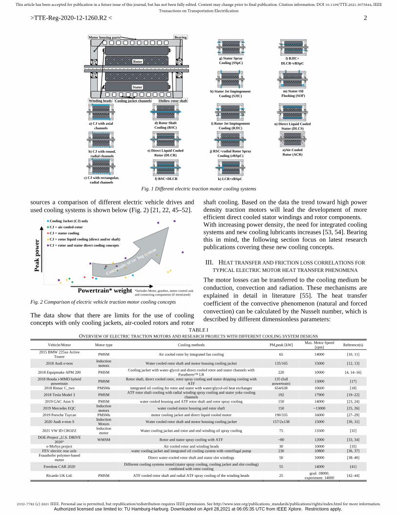
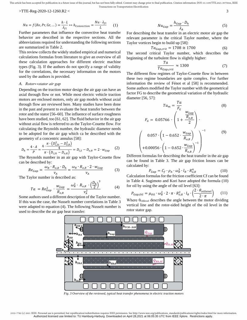


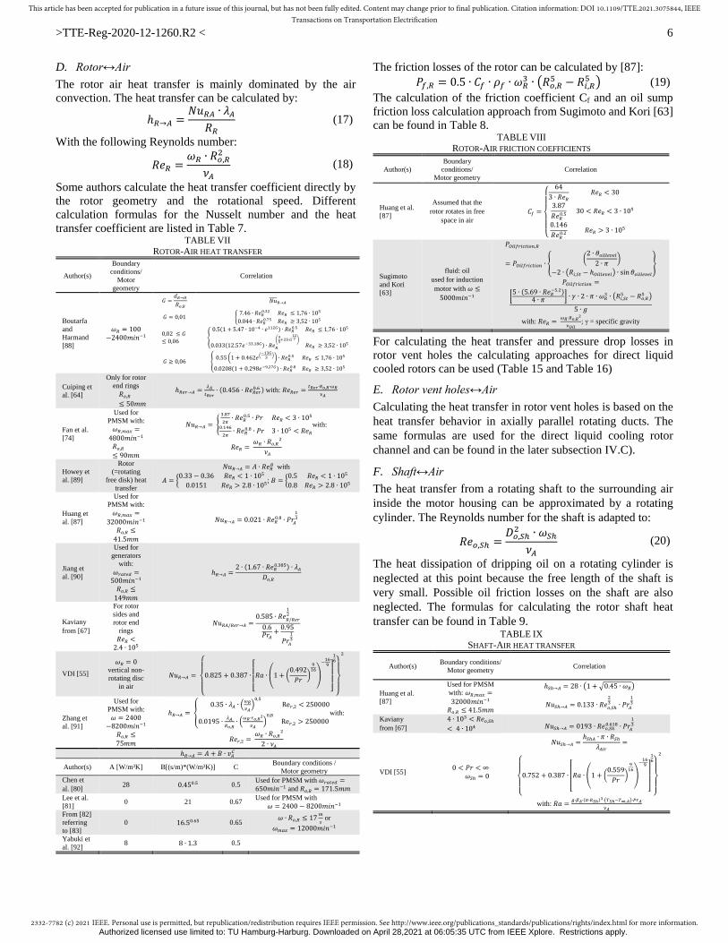
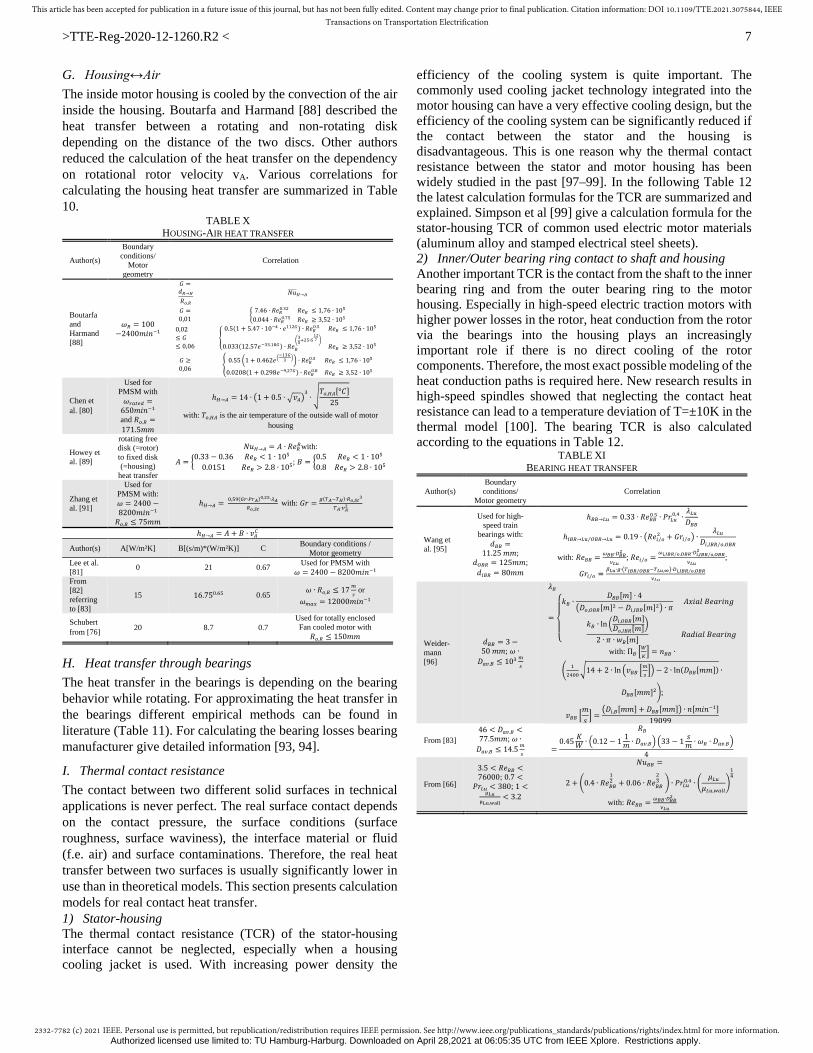


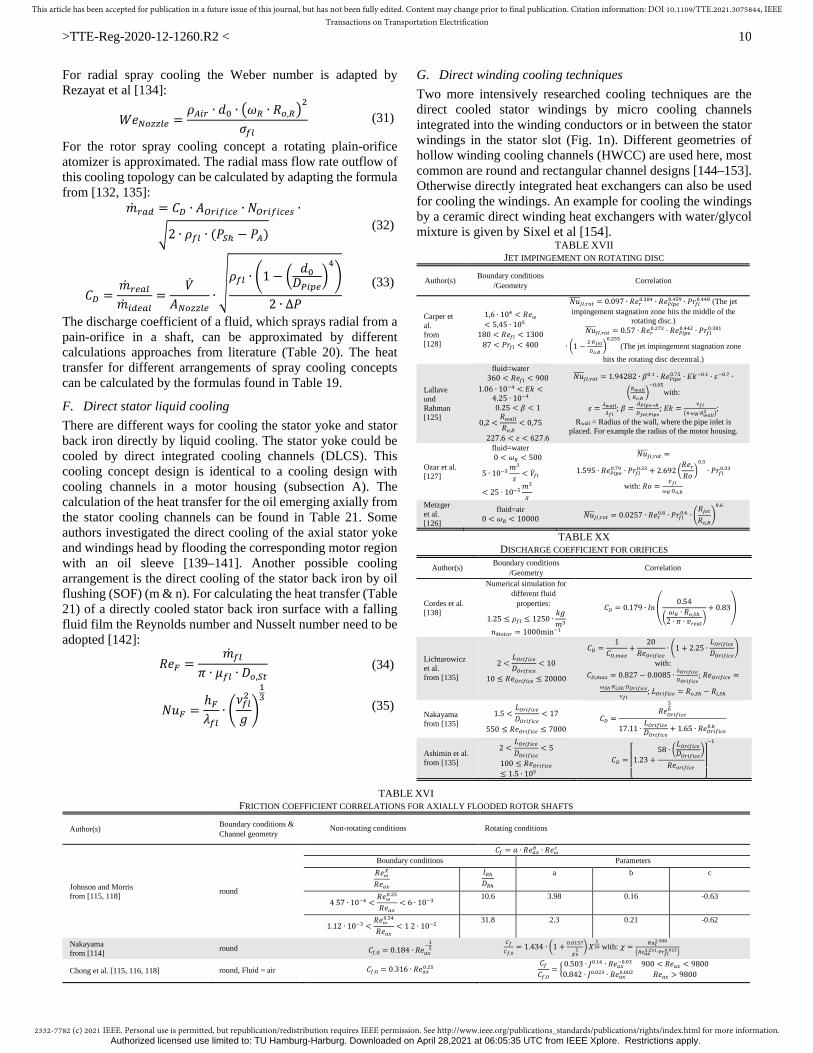
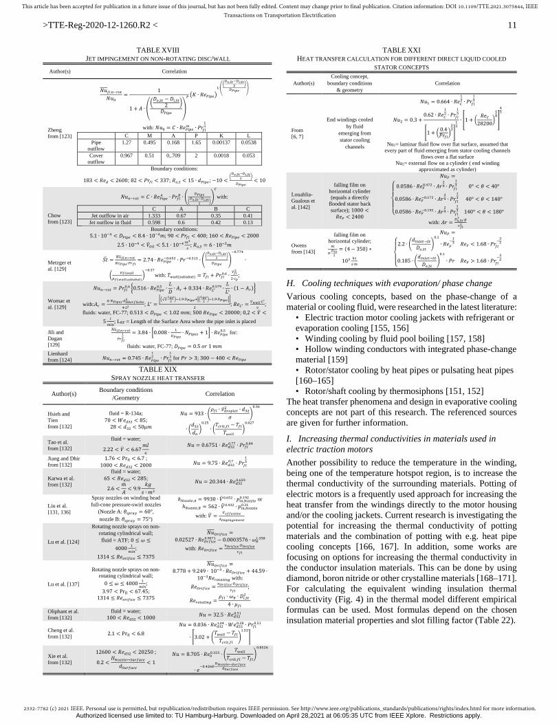
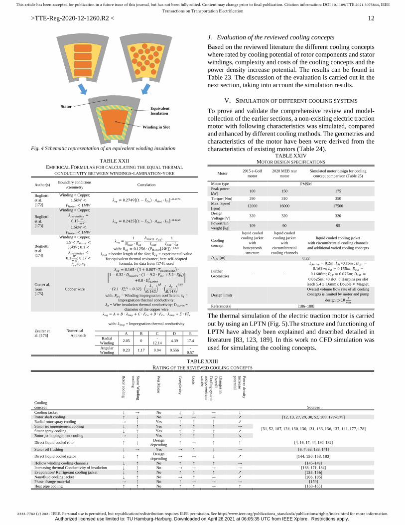
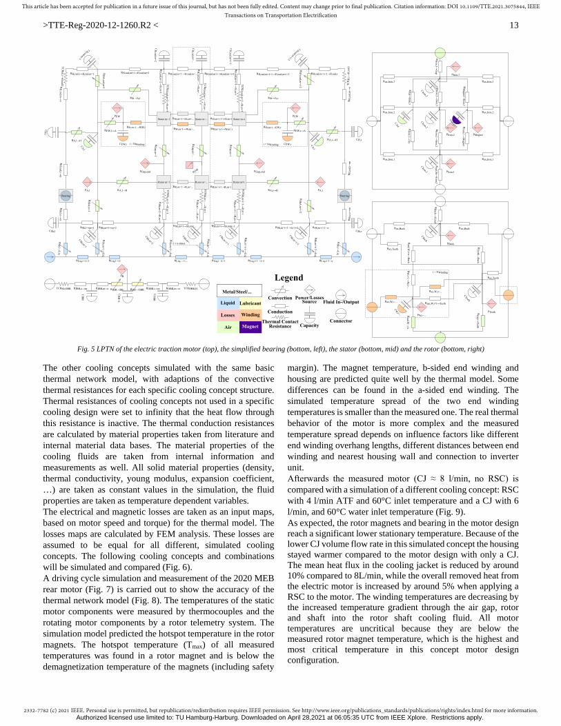

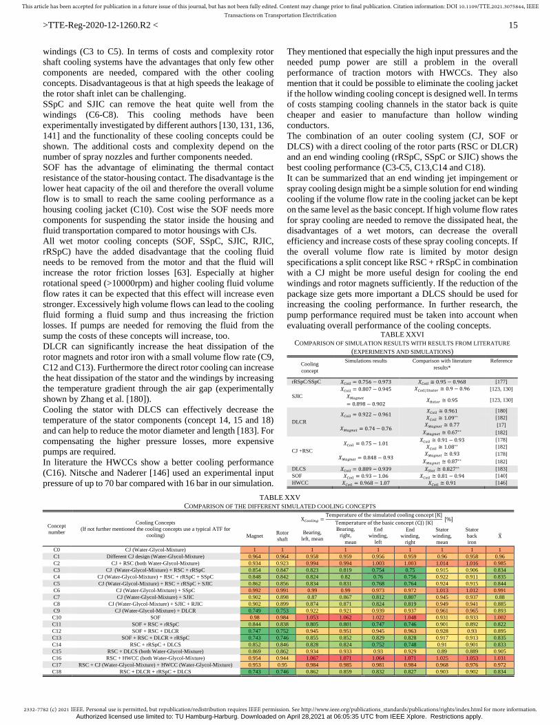


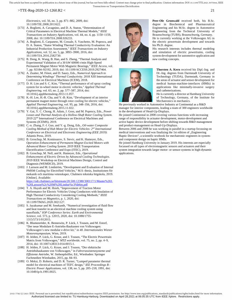


![Energy-Efficient Thermal-Aware Autonomic Management of ... › ~pompili › paper › thermal-aware_hpc.pdf · traction through cooling system optimization as in [20, 44–46] or](https://static.documents.pub/doc/80x56/5f135342136de43d3467e163/energy-efficient-thermal-aware-autonomic-management-of-a-pompili-a-paper.jpg)


