22
TRAFFIC IMPACT ANALYSIS (TIA) AND ACCESS MANAGEMENT GUIDELINES Revised May 2020
TRAFFIC IMPACT ANALYSIS (TIA) AND ACCESS MANAGEMENT GUIDELINES
Revised May 2020

i May 2020
TABLE OF CONTENTS
INTRODUCTION ............................................................................................................................................................. 1 TIA CATEGORIES ............................................................................................................................................................ 1
TRAFFIC IMPACT STATEMENT (TIS) ......................................................................................................................3 TRAFFIC IMPACT ANALYSIS (TIA) ..........................................................................................................................4
SCOPE OF STUDY ........................................................................................................................................................... 4 DATA COLLECTION ......................................................................................................................................................... 5 NEW TRIPS FROM PROPOSED DEVELOPMENT .............................................................................................................. 7
TRIP GENERATION ................................................................................................................................................7 INTERNAL CAPTURE AND PASS-BY PERCENTAGE .................................................................................................7 TRIP DISTRIBUTION AND TRAFFIC ASSIGNMENT .................................................................................................8
BACKGROUND TRAFFIC ................................................................................................................................................. 8 LEVEL-OF-SERVICE ANALYSIS ......................................................................................................................................... 8
ROADWAY SEGMENTS .........................................................................................................................................9 INTERSECTIONS ....................................................................................................................................................9
ACCESS MANAGEMENT ............................................................................................................................................... 10 INTERSECTIONS ..................................................................................................................................................10 MEDIAN OPENINGS ............................................................................................................................................10 DRIVEWAY SPACING AND LOCATION .................................................................................................................11
DRIVEWAY DESIGN ...................................................................................................................................................... 12 AUXILIARY LANES ......................................................................................................................................................... 12
LEFT-TURN LANES ...............................................................................................................................................12 RIGHT-TURN LANES ............................................................................................................................................12 QUEUING ANALYSIS ...........................................................................................................................................13
ROADWAY FUNCTIONAL CLASSIFICATION AND CIRCULATION MAP ........................................................................... 13 TRANSIT, BICYCLE, AND PEDESTRIAN FACILITIES ......................................................................................................... 14 ON-SITE CIRCULATION ................................................................................................................................................. 14 SAFETY ANALYSIS ......................................................................................................................................................... 15
CRASH ANALYSIS ................................................................................................................................................15 SIGHT DISTANCE .................................................................................................................................................15 INTERLOCKING AND BACK-TO-BACK LEFT-TURN LANES ....................................................................................15
MITIGATION MEASURES .............................................................................................................................................. 15 TRAFFIC SIGNAL WARRANT ANALYSIS ......................................................................................................................... 15 ADDITIONAL CRITERIA FOR K-12 SCHOOL SITES .......................................................................................................... 16 COORDINATION WITH OTHER PUBLIC AGENCIES ........................................................................................................ 17 REPORT FORMAT ......................................................................................................................................................... 18 APPENDIX A – PE-251-3 Driveway Criteria .................................................................................................................. 19 APPENDIX B – Planning Level Roadway Capacity Table ............................................................................................... 20
1 Rev. May 2020
INTRODUCTION One of the City of Peoria’s primary objectives is to operate and maintain a safe and efficient roadway system. The review and management of development-generated traffic is an integral part of that objective. The Traffic Impact Analysis (TIA) procedures as outlined in this document have been established for this purpose. The TIA procedures establish a range of Traffic Impact Analysis categories based on the characteristics of development and estimated peak hour traffic volumes. The TIA procedures also outline the analysis approach and methods. A TIA identifies existing traffic volumes and conditions, development traffic volumes and conditions and their combined impacts on the existing and future roadway system. Additionally, a TIA analyzes traffic circulation both on- and off- site. This is a useful tool for early identification of potential traffic problems and can play an important part in the success of a development. The need for a TIA should be assessed as early as possible in the development process when there is maximum flexibility to mitigate traffic-related problems. The results of the TIA can also affect the Site Plan or development proposal, so it is important to begin the traffic analysis early and incorporate the TIA recommendations into the development plans during design. The procedures contained herein are provided to assist developers through the approval process by outlining the requirements and level of detail of traffic analysis that will be required of them during the approval process, to standardize the types and details of analysis required in the assessment of traffic impacts and to ensure consistency in the preparation and review of a TIA. The purpose of this document is to provide criteria for the preparation of Traffic Impact Analysis (TIA) or a Traffic Impact Statement (TIS) for new land developments or additions to existing developments and to establish the report format for these studies.
TRAFFIC IMPACT ANALYSIS (TIA) CATEGORIES A TIA or TIS prepared by a Registered Professional Engineer in the State of Arizona is required for most developments. The requirement for a TIS for developments generating fewer than 100 peak hour trips may be waived by the City Traffic Engineer. Peak hour trips shall be estimated utilizing the most recent edition of the Institute of Transportation Engineers’ (ITE) Trip Generation Manual or other relevant data as approved by the City Traffic Engineer. The developer should initially identify the land use, number of units, and estimated number of daily, AM, and PM peak hour vehicle trips that will be generated by the proposed development to determine the level of analysis. A pre-TIA scoping meeting should be scheduled during the pre-application meeting for TIAs falling in Categories 1 through 4 to discuss the methodology to be used in the analysis. In addition to the existing conditions, the study must analyze the horizon year(s) and study area as stated in Table 1: Traffic Impact Analysis Categories.

2 Rev. May 2020
Table 1: Traffic Impact Analysis Categories
Traffic Impact Analysis Categories
TIA Category
Trip Generation Threshold1 Horizon Year(s)2 Study Area
Traffic Impact Statement
Developments that are estimated to generate less than 100 trips during the
highest peak hour.
Opening Year To be determined by City Traffic Engineer
1
Developments that are estimated to generate greater
than 100 but less than 500 vehicle trips during the
highest peak hour.
Opening Year and 5 years in the
future
1. Site access drives 2. All major signalized and
unsignalized intersections within ¼ mile and all major driveways within 500 feet
3. All roadway segments within ¼ mile of the project site boundary
2
Developments that are estimated to generate more than 500 but less than 1,000
vehicle trips during the highest peak hour.
Opening Year plus 5 and 10 years in
the future (phasing of the development
must also be considered)
1. Site access drives 2. All major signalized and
unsignalized intersections and all major driveways within a ½ mile radius of the project site boundary
3. All roadway segments within ½ mile of the project site boundary
3
Those developments that are estimated to generate more
than 1,000 but less than 1,500 vehicle trips during the
highest peak hour.
Opening Year plus 5, 10, 15 years in
the future (phasing of the development
must also be considered)
1. Site access drives 2. All major signalized and
unsignalized intersections and all major driveways within a 1-mile radius of the project site boundary
3. All roadway segments within 1 mile of the project site boundary
4
Regional Development generating 1,500 or greater trips during the highest peak
hour.
Opening Year plus 5, 10, 15, and 20 years in future or as specified in the Phasing Schedule
1. Site access drives 2. All major signalized and
unsignalized intersections and all major driveways within an impact area defined during the scoping meeting
3. All roadway segments within an impact area defined during the scoping meeting
1. The trip generation used for determining the TIA category shall not be reduced for internal or pass-by trips unless approved by the City Traffic Engineer. For developments with peaks different than the typical adjacent street peak such as churches, schools, shift work, sports complex, movie theater, etc., the peak hour of the generator shall be calculated.
2. The Traffic Impact Analysis shall consider the phasing of the development and make infrastructure improvement
recommendations so an adequate level-of-service (LOS) is maintained with each phase of development.

3 Rev. May 2020
TRAFFIC IMPACT STATEMENT (TIS) If the proposed project generates fewer than 100 peak hour trips, a TIS that addresses trip generation and any site-specific issues may be submitted in lieu of a full Traffic Impact Analysis. The TIS shall be signed and sealed by a Registered Professional Engineer in the State of Arizona. The following should be included in the TIS: Description of Existing Conditions Roadways, including existing street cross-section, street classification, posted speed limit,
daily traffic volume, and 85th percentile speed (if available) Intersections, including existing lane configuration and traffic control Nearby driveways (adjacent, opposite and off-set), including locations and spacing Sight distance deficiencies Surrounding Land Use Transit, Pedestrian, and Bicycle facilities and access
Description of Proposed Development Location Site Plan, including spacing of driveways and distance from nearest intersection and other
driveways, including opposite and off-set) Land Use & Project Size Hours of operation, if known Access, including location, type (full, partial, right-in/right-out), spacing (must follow
Peoria’s Access Management criteria), and alignment with existing/future driveways On-site Circulation and Queuing (if appropriate) Transit, Pedestrian, and Bicycle facilities and access
Trip Generation Calculate and summarize the daily, AM, and PM peak hour traffic. For developments with
peaks different than the adjacent street peak, such as churches, schools, shift work, sports complex, movie theater, etc., the peak hour of the generator shall be calculated.
Street Classification and Circulation Map Discuss street classification and adherence to Peoria’s Circulation Map.
Additional Site-Specific Analyses Additional site-specific analyses may be required at the request of the City Traffic
Engineer. When an auxiliary lane analysis is required, a distribution and assignment of site traffic is
required to evaluate location and storage lengths. Refer to Peoria’s requirement for right-turn deceleration lanes.
4 Rev. May 2020
TRAFFIC IMPACT ANALYSIS (TIA): A TIA is required for all projects that generate 100 or more trips during either the AM or PM peak hour. The most recent version of the ITE Trip Generation Manual should be used for all trip generation calculations. Traffic Impact Analysis will be classified into four categories:
Category 1: Proposed developments that are deemed to have minor traffic impacts. Category 2: Proposed developments that have localized impacts to the City’s
transportation system. Category 3: Proposed developments that have major impacts to the transportation
system that may extend beyond the vicinity of the site. Category 4: Proposed developments that have regional impacts to the transportation
system that extend beyond the vicinity of the site and may cross jurisdictional boundaries.
SCOPE OF STUDY
PRE-TIA SCOPING MEETING The purpose of the pre-TIA Scoping Meeting is to discuss the project scope and required/expected level of analysis to be performed by the engineer completing the TIA. Study intersections, time periods, horizon year(s), required traffic counts, intersections needing traffic signal warrant analysis, and future adjacent developments will be identified. Applicants should contact the Development and Engineering Services, Traffic Engineering Division to request a pre-TIA Scoping Meeting to determine the analysis requirements of the TIA.
STUDY AREA (See Table 1) The analysis shall include all intersections of two or more streets with a functional classification of Minor Collector or greater in the study area. Additional intersections, such as local streets or commercial driveways may be included in the analysis, if required by the City Traffic Engineer or if in close proximity to (adjacent, opposite or off-set) or align with proposed driveways/roadways.

5 Rev. May 2020
HORIZON YEAR(S) (See Table 1) The horizon years shall consider proposed phasing to adequately assess the timing of improvements and/or necessary interim improvements. The TIA horizon years shall correlate to the phasing of the development so infrastructure improvements are in place to maintain an acceptable level-of-service (LOS) with each phase.
ANALYSIS TIME PERIODS The study should include an analysis of the impact of the traffic generated by the development for the typical adjacent street peak hour conditions, which normally occur within the AM and PM peak periods on a typical weekday. Roadway segment analysis shall be conducted for average daily traffic (ADT) and peak hours. The City may require additional time periods if the development has unusual peaking characteristics such as a church, school, shift work, sports complex, movie theater, etc. or if the adjacent non-site traffic conditions warrant an analysis of other peak traffic time periods.
DATA COLLECTION The TIA shall include information on the following existing and proposed conditions within the study area:
EXISTING TRAFFIC VOLUMES The Traffic Engineer preparing the TIA shall obtain approval of the scope of study from Peoria Traffic Engineering Division staff before ordering traffic counts and submitting the TIA. The TIA shall provide daily traffic volumes, which are available on Peoria’s annual traffic volume and speed map for most Parkway, Major and Minor Arterial and Major and Minor Collector roadways. For study roadways without known daily traffic volumes, 24-hour segment counts shall be collected. Additionally, for study intersections identified in the pre-TIA scoping meeting, turning movement traffic counts in 15-minute intervals shall be conducted during the AM and PM peak hours. The TIA shall also include pedestrian and bicycle counts (for turning movement counts only, not street segment counts). The existing traffic volumes and daily and peak hour turning movements shall be depicted on a figure in the TIA report. Unsignalized study intersections requiring a traffic signal warrant analysis shall be identified in the pre-TIA Scoping Meeting. Turning movement counts for a 24-hour period in 15-minute periods shall be obtained for each study intersection requiring a traffic signal warrant analysis. For future driveways anticipated to warrant a traffic signal, 24-hour traffic counts shall be conducted on the adjacent street. If 24-hour turning movement traffic counts are not conducted for intersections requiring a traffic signal warrant analysis, the TIA may need to be revised and resubmitted.
6 Rev. May 2020
Typical AM peak hours are 7:00 to 9:00 AM and typical PM peak hours are 4:00 to 6:00 PM. Different time periods may be required for developments with different peaking characteristics, such as churches, schools, shift work, sport complexes, movie theaters, etc. Saturday and Sunday counts may be required for some commercial uses, churches, sport complexes, etc.
FUTURE BACKGROUND TRAFFIC VOLUMES
When appropriate, obtain traffic projections from the Maricopa Association of Governments (MAG), relevant documented traffic projection sources, volumes from TIAs prepared for nearby developments, or historical traffic volume trends. Future background traffic volumes shall be estimated for each horizon year.
SURROUNDING LAND USE
Identify the existing land uses within the study area.
PROPOSED DEVELOPMENT
Relevant details for the proposed development need to be obtained such as size (dwelling units, square feet, students, employees, etc.), hours of operation, on-site circulation, alternative transportation infrastructure for transit, bicycles, pedestrians, and site access. Distances between access points shall be labeled on the site plan as well as locations of adjacent driveways and intersections to verify proper spacing. Streets or driveways in close proximity to other streets or driveways may be required to align for on- or off-site circulation. Drive aisles and their alignments will be reviewed for on-site access and circulation. A location map and site plan shall be included in the TIA.
EXISTING TRANSPORTATION SYSTEM
Existing characteristics shall be identified, including street cross-section, type and location of median openings, speed limits, functional classification, intersection lane configuration, traffic control devices, sight distance, and alternative transportation facilities for transit, bicycles, and pedestrians. The alternative transportation facilities include bicycle lanes, sidewalks, trails, bus routes and bus shelters, and shared ride pick-up/drop-off. The existing transportation system shall be depicted on a figure in the TIA.
FUTURE TRANSPORTATION SYSTEM
Future transportation improvements for all modes of transportation and their timing should be identified along with reviewing relevant traffic studies.
CRASH DATA
Crash data for a three-year period shall be obtained for the study area.
7 Rev. May 2020
NEW TRIPS FROM PROPOSED DEVELOPMENT
TRIP GENERATION
The trip generation for any proposed development shall be estimated using the latest edition of Trip Generation Manual published by ITE. Exceptions to the use of this document must be approved by the City and may include actual trip generation counts from an existing facility of similar size, land use and surrounding area characteristics or from other recognized sources that provide trip generation data not included in the ITE Manual. The trip generation shall be summarized in a table in the TIA report.
INTERNAL CAPTURE AND PASS-BY PERCENTAGE
Typically, all trips entering and exiting a new development are new trips not made to or through the area prior to the development being completed. However, for some non-residential developments, a portion of these trips may be “captured” from trips already being made to other existing developments on the adjacent street system or they may be merely passing by on the way from one place to another. The driveway volume for a new development may be significantly different from the traffic volume added to the adjacent street system. For example, retail establishments, restaurants, banks, service stations, and convenience markets attract people from the passing stream of traffic. These are known as pass-by trips. ITE’s Trip Generation Handbook contains discussions and references on the issue of pass-by trips. Because of the limited data available, adjustments for pass-by trips should be applied carefully. If pass-by trips are a major consideration, studies and interviews at similar land uses must be conducted or referenced. The use of internal capture and pass-by percentage reductions will be allowed for certain types and sizes of Mixed-Use Developments. Allowable sources for internal capture and pass-by reduction rates for land uses are identified below:
1. The internal capture rates or equations contained in the most recent version of the ITE Trip Generation Manual, as approved for use by the City.
2. The internal capture rate from a previously approved City of Peoria TIA of similar land uses, if approved by the City Traffic Engineer.
3. Any proposed internal capture rates shall be approved by the City Traffic Engineer in writing prior to implementation.
Any trip reduction adjustments applied to reflect pass-by traffic, internal capture, alternative modes, carpooling (TDM), or other means shall be clearly identified and documented in the TIA and discussed with the City Traffic Engineering Division staff prior to use within the report.

8 Rev. May 2020
TRIP DISTRIBUTION AND TRAFFIC ASSIGNMENT
Manual traffic distribution and assignment based on the gravity model principle can be accomplished using experience, judgment, and knowledge of local conditions. Site traffic shall be assigned to the proposed site driveways and street network system included within the study area based on the distribution of existing traffic counts, an analysis of future market area within the area of influence, or by computer-based modeling software. However, projects generating more than 300 peak-hour trips may be required to use either MAG's model or as identified and approved during the pre-TIA meeting. A figure depicting the assumed distribution percentages is required in the TIA. Figures are also required illustrating the daily and peak hour site traffic for each phase of development.
BACKGROUND TRAFFIC Future projected background traffic volumes should be based on available traffic projections from MAG, other relevant and documented traffic projection sources, volumes from TIAs prepared for nearby developments, or historical traffic volume trends analyses. Projected traffic volumes shall include adjustments, as necessary, to reflect other adjacent future development and seasonal trends. Trend growth rates from historic count data may also be utilized to project future background traffic volumes. Sources and background growth rates shall be clearly identified in the TIA. Figures depicting the background traffic volumes and daily and peak hour turning movement are required in the TIA for each horizon year.
LEVEL-OF-SERVICE ANALYSIS Per the Peoria Engineering Standards Manual (PESM), the desired level-of-service (LOS) designations for all roadway segments shall be used in the traffic analysis to support street classifications and the sizing of interim roadways. At each intersection, the LOS for each movement shall be analyzed, in order to determine the required mitigation to maintain an acceptable LOS. Infrastructure improvements shall be recommended for each phase so that an adequate LOS is maintained with each phase of development. LOS analyses are required for the following scenarios:
1. Existing conditions 2. Future non-site background traffic conditions for each horizon year/phase 3. Future total background plus project traffic conditions for each horizon year/phase
9 Rev. May 2020
ROADWAY SEGMENTS
All study area roadway segments shall be reviewed to determine daily traffic volume and recommended appropriate street sizing and classification. Refer to the Planning Level Roadway Capacity table included in Appendix B for guidance with roadway sizing.
INTERSECTIONS
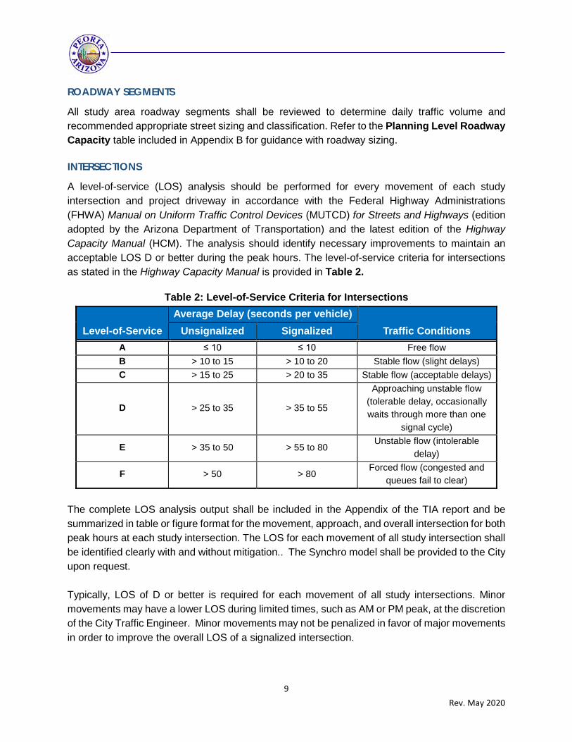
A level-of-service (LOS) analysis should be performed for every movement of each study intersection and project driveway in accordance with the Federal Highway Administrations (FHWA) Manual on Uniform Traffic Control Devices (MUTCD) for Streets and Highways (edition adopted by the Arizona Department of Transportation) and the latest edition of the Highway Capacity Manual (HCM). The analysis should identify necessary improvements to maintain an acceptable LOS D or better during the peak hours. The level-of-service criteria for intersections as stated in the Highway Capacity Manual is provided in Table 2.
Table 2: Level-of-Service Criteria for Intersections
Level-of-Service Average Delay (seconds per vehicle)
Traffic Conditions Unsignalized Signalized A ≤ 10 ≤ 10 Free flow B > 10 to 15 > 10 to 20 Stable flow (slight delays) C > 15 to 25 > 20 to 35 Stable flow (acceptable delays)
D > 25 to 35 > 35 to 55
Approaching unstable flow (tolerable delay, occasionally waits through more than one
signal cycle)
E > 35 to 50 > 55 to 80 Unstable flow (intolerable
delay)
F > 50 > 80 Forced flow (congested and
queues fail to clear) The complete LOS analysis output shall be included in the Appendix of the TIA report and be summarized in table or figure format for the movement, approach, and overall intersection for both peak hours at each study intersection. The LOS for each movement of all study intersection shall be identified clearly with and without mitigation.. The Synchro model shall be provided to the City upon request. Typically, LOS of D or better is required for each movement of all study intersections. Minor movements may have a lower LOS during limited times, such as AM or PM peak, at the discretion of the City Traffic Engineer. Minor movements may not be penalized in favor of major movements in order to improve the overall LOS of a signalized intersection.
10 Rev. May 2020
ACCESS MANAGEMENT Per the Peoria Engineering Standards Manual, new commercial sites shall coordinate and provide access to existing and future adjacent commercial centers whenever possible.
INTERSECTIONS
Per the Peoria Engineering Standards Manual, Collector streets shall not intersect Parkway, Major Arterial, or Minor Arterial streets at spacing other than ¼ mile or ½ mile points of an arterial. Local residential streets shall not intersect parkway or arterial roadways. Where street and driveway intersections are restricted to partial access, a raised median shall be required to reinforce access restrictions. Turn diverter islands may be used in conjunction, but shall not be used in lieu of a raised median.
MEDIAN OPENINGS
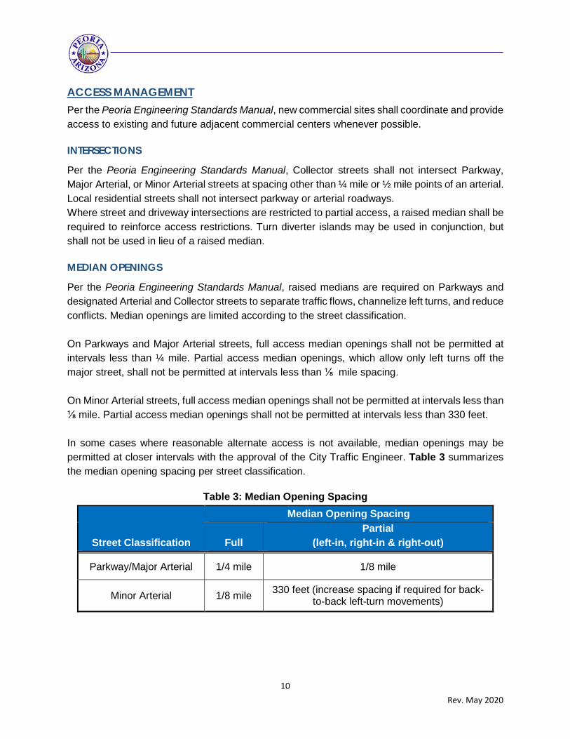
Per the Peoria Engineering Standards Manual, raised medians are required on Parkways and designated Arterial and Collector streets to separate traffic flows, channelize left turns, and reduce conflicts. Median openings are limited according to the street classification. On Parkways and Major Arterial streets, full access median openings shall not be permitted at intervals less than ¼ mile. Partial access median openings, which allow only left turns off the major street, shall not be permitted at intervals less than ⅛ mile spacing. On Minor Arterial streets, full access median openings shall not be permitted at intervals less than ⅛ mile. Partial access median openings shall not be permitted at intervals less than 330 feet. In some cases where reasonable alternate access is not available, median openings may be permitted at closer intervals with the approval of the City Traffic Engineer. Table 3 summarizes the median opening spacing per street classification.
Table 3: Median Opening Spacing
Street Classification
Median Opening Spacing
Full Partial
(left-in, right-in & right-out)
Parkway/Major Arterial 1/4 mile 1/8 mile
Minor Arterial 1/8 mile 330 feet (increase spacing if required for back-to-back left-turn movements)
11 Rev. May 2020
DRIVEWAY SPACING AND LOCATION
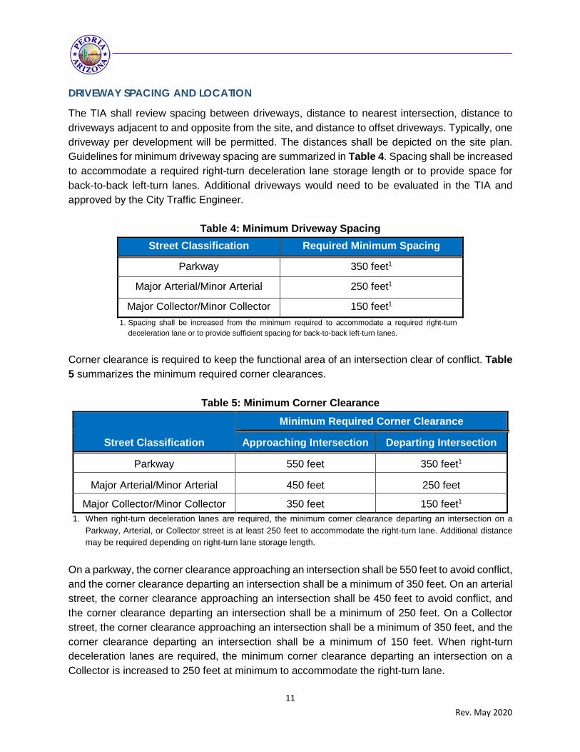
The TIA shall review spacing between driveways, distance to nearest intersection, distance to driveways adjacent to and opposite from the site, and distance to offset driveways. Typically, one driveway per development will be permitted. The distances shall be depicted on the site plan. Guidelines for minimum driveway spacing are summarized in Table 4. Spacing shall be increased to accommodate a required right-turn deceleration lane storage length or to provide space for back-to-back left-turn lanes. Additional driveways would need to be evaluated in the TIA and approved by the City Traffic Engineer.
Table 4: Minimum Driveway Spacing Street Classification Required Minimum Spacing
Parkway 350 feet1
Major Arterial/Minor Arterial 250 feet1
Major Collector/Minor Collector 150 feet1 1. Spacing shall be increased from the minimum required to accommodate a required right-turn
deceleration lane or to provide sufficient spacing for back-to-back left-turn lanes.
Corner clearance is required to keep the functional area of an intersection clear of conflict. Table 5 summarizes the minimum required corner clearances.
Table 5: Minimum Corner Clearance
Street Classification
Minimum Required Corner Clearance
Approaching Intersection Departing Intersection
Parkway 550 feet 350 feet1
Major Arterial/Minor Arterial 450 feet 250 feet
Major Collector/Minor Collector 350 feet 150 feet1 1. When right-turn deceleration lanes are required, the minimum corner clearance departing an intersection on a
Parkway, Arterial, or Collector street is at least 250 feet to accommodate the right-turn lane. Additional distance may be required depending on right-turn lane storage length.
On a parkway, the corner clearance approaching an intersection shall be 550 feet to avoid conflict, and the corner clearance departing an intersection shall be a minimum of 350 feet. On an arterial street, the corner clearance approaching an intersection shall be 450 feet to avoid conflict, and the corner clearance departing an intersection shall be a minimum of 250 feet. On a Collector street, the corner clearance approaching an intersection shall be a minimum of 350 feet, and the corner clearance departing an intersection shall be a minimum of 150 feet. When right-turn deceleration lanes are required, the minimum corner clearance departing an intersection on a Collector is increased to 250 feet at minimum to accommodate the right-turn lane.

12 Rev. May 2020
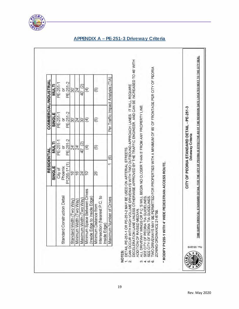
DRIVEWAY DESIGN Driveways shall follow the City of Peoria’s Standard Detail PE-251-3 included in Appendix A. Driveway widths shall be analyzed for necessary turning radii, truck turning movements, and ingress/egress lanes. Driveway lengths shall be reviewed for minimum throat length needed to accommodate all inbound traffic safely on-site without backups onto the intersecting street, and to accommodate all outbound traffic queued at the driveway to exit without blocking intersecting drive aisles, median openings, or parking spaces. The effective length of a vehicle shall be measured in increments of 25-feet. Per the Peoria Engineering Standards Manual, the minimum throat length of all accesses/driveways shall be 100 feet. For commercial driveways that could potentially be signalized, the minimum throat length shall be 150 feet. Longer throat lengths may be required based on the requirements of the TIA. Driveways may be required to align with existing or future driveways or streets in close proximity for proper on- or off-site circulation and to reduce vehicle conflicts at the discretion of the City Traffic Engineer.
AUXILIARY LANES When warranted, turn lanes permit separation of conflicting traffic movements and remove slower turning traffic from through traffic, improving capacity and reducing rear-end crashes. Determining the need for turn lanes is a key element of a TIA.
LEFT-TURN LANES
Left-turn lanes should be provided on Parkways, Major and Minor Arterials, and Major Collector streets. Per the Peoria Engineering Standards Manual, dual left-turn lanes should be considered at signalized intersections when the turn volume exceeds 200 vehicles per hour (VPH), the opposing through volume exceeds 1,000 VPH, or the delay to left turning vehicles exceeds 45 seconds.
RIGHT-TURN LANES
Right-turn lanes shall be provided on each approach for Arterial/Arterial and Arterial/Collector intersections. Per the Peoria Engineering Standards Manual, right-turn lanes shall be provided at driveways on streets classified as Major Arterial or higher, and at street intersections and driveways where warranted. Right-turn deceleration lanes shall be provided at driveways on roadways meeting any of the following criteria:
1. At driveways when the roadway is classified as Major Arterial or higher. 2. At least 30 vehicles are expected to make right turns into the driveway(s) during any one-
hour period (existing or future). 3. Sites with a larger than average number of heavy vehicles (industrial, storage, and
warehouse uses).

13 Rev. May 2020
Deceleration lanes may be required at additional driveways not meeting these criteria, at the discretion of the City Traffic Engineer. Adjacent driveways shall not be located within the area of a deceleration lane or taper, unless approved by the City Traffic Engineer.
QUEUING ANALYSIS
The storage length of turn lanes depends on several factors and must be determined on a case-by-case base and approved by the City Traffic Engineer. The TIA should recommend minimum storage lengths based on a queuing analysis. The queuing analysis should be performed using accepted formulas as specified in the AASHTO A Policy on Geometric Design of Highways and Streets and with proper documentation. 95th percentile queue lengths from the LOS analysis should also be referenced when determining the recommended storage lengths.
A. Storage lane lengths shall be determined based on a minimum length of 25 feet per vehicle during the highest peak hour. The minimum length of a storage lane shall be 100 feet, unless otherwise approved by the City Traffic Engineer.
B. The lengths of deceleration lanes outlined in this section do not include taper length.
Deceleration lane tapers should be approximately 12.5-feet longitudinally per 1-foot transversely (12.5:1), typically a 150’ taper for a 12’ wide lane.
C. The City Traffic Engineer may require longer storage lengths and/or tapers for deceleration lanes based on specific site conditions.
For all right- and left-turn lanes, a table shall be provided in the TIA report that summarizes the existing (if applicable), required (as calculated per the TIA), and recommended storage lengths for all driveways and intersections analyzed.
ROADWAY FUNCTIONAL CLASSIFICATION AND CIRCULATION MAP Identify the functional street classification for existing and proposed roadways within the study area and determine if proposed roadways follow the General Plan Circulation Plan. Any slight deviation shall provide adequate justification for modification. Refer to the Planning Level Roadway Capacity table included in Appendix B for guidance with roadway sizing. Areas within the City without an existing or proposed roadway shown on the Circulation Plan shall provide a sufficient roadway network that addresses the proposed development and provides future local and regional connections to adjacent land.

14 Rev. May 2020
TRANSIT, BICYCLE, AND PEDESTRIAN FACILITIES The TIA shall discuss the existing and proposed transit, bicycle, and pedestrian facilities that encourage alternative modes of transportation. This includes current and proposed features (nearest bus stops, distance to bicycle lanes/routes, off-road shared-use path locations, public sidewalk connections). Incorporate potential ridership, cyclist, and pedestrian counts and on-site amenities. Developments that generate pedestrian activity as an origin or destination shall discuss pedestrian and bicycle access across any adjacent or nearby Arterial or Collector street. The development may need to provide appropriate pedestrian crossing infrastructure if not existing and available within ⅛ mile of each access to the development. Typically, arterial streets crossings require a Pedestrian Hybrid Beacon (PHB). for additional information on appropriate pedestrian treatments based on roadway configuration, ADT, and speed. The proposed development shall provide stubs and access points along the edge of the proposed development to create contiguous networks. Refer to the Peoria Engineering Standards Manual for pedestrian and bicycle design.
ON-SITE CIRCULATION Adequate on-site circulation is essential to provide safe and efficient access. The analysis shall provide a circulation plan with a figure and assessment of circulation internal to the development, including all accessways and easements, as well as access routes to adjacent developments.. On-site drive aisles and alignments will be reviewed for safe and efficient on-site circulation. Streets or driveways in close proximity to other streets or driveways may be required to align for on- or off-site circulation. Drive aisles and their alignments will be reviewed for on-site access and circulation. All internal drive aisle intersections shall provide a minimum 15’ x 15’ sight triangle. On-site circulation shall address transit, bicycle, and pedestrian facilities and demonstrate a non-conflicting access route throughout the development and connection to off-site facilities. Additionally, a queuing analysis shall be included to demonstrate the site has adequate storage for all turn lanes, drive-thru lanes, and drop-off/pick-up zones. The effective length of a vehicle shall be measured in increments of 25-feet. Drive-in and drive-thru establishments shall be provided with adequate queue storage capacity to accommodate normal peak queues for the specified land use. Because many of these businesses have major daily or seasonal variations in activity, peaking characteristics should be carefully evaluated, and cannot be less than the required length prescribed in the Peoria Zoning Ordinance.
15 Rev. May 2020
Planned commercial sites that consist of two or more parcels shall have internal connectivity that is clear of obstacles to minimize the impact to the adjacent streets. New commercial sites shall coordinate and provide access to existing adjacent commercial centers whenever possible. Exceptions must be submitted to the Development & Engineering Director with an accompanied traffic study for review and approval.
SAFETY ANALYSIS
CRASH ANALYSIS
Crash data for three-year period should be reviewed within the study area to identify trends and/or potential safety hazards.
SIGHT DISTANCE
Existing or potential sight distance deficiencies should be identified. For local/local intersections, the City of Peoria standard detail PE-091 shall be applied. For any street or driveway intersection with a Collector or Arterial roadway, the City of Peoria standard detail PE-090 shall be applied. For roadways with vertical curvature, minimum intersection sight distances shall be evaluated per AASHTO.
INTERLOCKING AND BACK-TO-BACK LEFT-TURN LANES
Existing conditions and the proposed site accesses shall be reviewed to identify any conflicts with left-turn movements. Interlocking left-turn conflicts shall be identified and mitigated. Storage lengths for back-to-back left-turn lanes shall be calculated per the TIA and recommendations made to ensure safe operation.
MITIGATION MEASURES All recommended on-site and off-site improvements required to mitigate future projected traffic congestion or safety issues to maintain the before condition LOS or the minimum standard of LOS C or D shall be identified. The improvements shall be identified as by others or the responsibility of the development. Figures shall be included in the TIA depicting the future and recommended lane configuration and traffic control for each phase of development to adequately assess the timing of improvements and/or necessary interim improvements. The TIA horizon years shall correlate to the phasing of the development such that infrastructure improvements are in place to maintain an acceptable LOS with each phase.
TRAFFIC SIGNAL WARRANT ANALYSIS Study intersections currently unsignalized and needing a traffic signal warrant analysis shall be identified in the pre-TIA Scoping meeting. Turning movement counts for a 24-hour period in 15-minute periods including all vehicular, bicycle, and pedestrian movements shall be obtained for each study intersection requiring a traffic signal warrant analysis. The turning movement counts

16 Rev. May 2020
are important to identify an appropriate right-turn reduction. For future driveways anticipated to warrant a traffic signal, 24-hour traffic counts shall be conducted on the adjacent street. The traffic signal warrant analysis shall be conducted per the methodology in the most recent edition of the Manual of Uniform Traffic Control Devices (MUTCD), particularly the eight-hour warrant. Other signal warrants shall be applied when relevant and using engineering judgement. A right-turn volume reduction shall be applied per engineering judgement and verification with the City Traffic Engineer. Typically, right-turn volumes should not be considered when there is a dedicated right-turn lane. To estimate future hourly traffic volumes from the development for use in the traffic signal warrant analysis, the trip generation and trip assignment from the TIA shall be utilized and distributed per the hourly percentages provided in the ITE Trip Generation Manual or another relevant source. At least eight hours shall be estimated to consider the eight-hour traffic signal warrant. The appendices of ITE’s Trip Generation Manual provide percent of daily traffic during each hour of a weekday, Saturday, and Sunday for different land uses when available. When hourly traffic volumes are not available, the eighth highest hour shall be estimated per ADOT’s Traffic Engineering Guidelines and Processes (TGP) 611, Figure 611-A. Per Figure 611-A, the eighth highest hour is estimated by multiplying the AADT by 5.72 percent. The fourth highest hour is estimated by multiplying the AADT by 6.56 percent.
ADDITIONAL CRITERIA FOR K-12 SCHOOL SITES The study for any public, charter, or private school with students ranging in grades K-12 shall provide the following additional information:
a) Student Enrollment The maximum student enrollment at build out shall be indicated. Partial student enrollment may be discussed, but will not reduce drop-off/pick-up vehicle queue length requirements.
b) Parking The total number of parking spaces onsite shall be provided. Additional off-site parking available through shared-use facilities, such as adjacent parks or community centers, or on-street parking should be discussed as well.
c) School Traffic Circulation Overview A school traffic circulation overview with diagrams shall detail motor vehicle, bus, bicycle, and pedestrian circulation on site and on adjacent streets, including:
1. Direction of traffic flow and number of lanes throughout diagram; 2. Ingress and egress from the site;
17 Rev. May 2020
3. Minimum and high demand drop-off/pick-up vehicle queue lengths; 4. School bus loading areas; 5. A Suggested Route to School walking map of the proposed walking boundaries using
routes that minimize crossings of busy streets and busy driveways; and 6. A figure depicting all proposed school-related traffic control associated with the new
school
d) Drop-off/Pick-up Vehicle Queue The site shall accommodate a minimum and high demand vehicle queue for student drop-off and pick-up. The entire drop-off/pick-up vehicle queue should be contained within the school site and/or on a consenting adjacent shared-use site. The length of a right turn lane may be added to the high demand queue length, if approved by the City Traffic Engineer. These values take into account typical percentages of walking, bus riding, and carpooling students, and may not be reduced based on staggered start or dismissal times, after-school activities, or other special program expected to reduce the number of students arriving in vehicles.
1. Traditional Public Elementary Schools serving grades K-8: The minimum queue
length provided onsite shall be 1.7 feet per student based on the school’s maximum enrollment at build-out. Additionally, the site shall provide a contingency circulation plan that accommodates a high demand queue length of 2.2 feet per student based on the school’s maximum enrollment at build-out.
2. Charter, Magnet, or Private Schools: The minimum queue length provided onsite
shall be 4.3 feet per student based on the school’s maximum enrollment at build-out. Additionally, the site shall provide a contingency circulation plan that accommodates a high demand queue length of 5.5 feet per student based on the school’s maximum enrollment at build-out.
3. High Schools: The minimum queue length provided onsite shall be 0.6 feet per
student based on the school’s maximum enrollment at build-out. Additionally, the site shall provide a contingency circulation plan that accommodates a high demand queue length of 0.8 feet per student based on the school’s maximum enrollment at build-out.
COORDINATION WITH OTHER PUBLIC AGENCIES If applicable, the requirements for a Traffic Impact Analysis as noted in this document may need to be coordinated with the requirements of other local agencies such as adjacent cities or towns, the Maricopa County Department of Transportation, or the Arizona Department of Transportation. Any deviation from the requirements of this document due to the requirements of other agencies should be presented in written form to the City for review and approval or denial.
18 Rev. May 2020
REPORT FORMAT The TIA shall be sealed by a Professional Engineer in the State of Arizona and should include the following items and report sections:
Cover Page Table of Contents, List of Figures, and Tables Executive Summary and Introduction Scope of Study
-TIA Category -Study Area and Study Intersections -Horizon Years and Phasing -Analysis Time Periods
Study Area Map and Site Location Existing Conditions
-Discussion of Existing Traffic Counts -Description of Roadways and Street Classification -Description of Study Intersections and Traffic Control -Description of Alternative Transportation Facilities (transit, bicycle, pedestrian) -Existing Sight Distance Deficiencies -Existing LOS summarized in table or figure
Figure depicting daily and peak hour existing traffic volumes Figure of existing street cross-sections, intersection lane configuration, and traffic control Description of Existing and Surrounding Land Use Discussion of Future Transportation Improvements Project Description
-Land Use (size, units, employees, students) -Operation Hours -Phasing -Access points and Spacing -Transit, Bicycle and Pedestrian Facilities
Site Plan with Access Points and Driveway Spacing Labeled Trip Distribution (Document sources and assumptions and depict distribution on figure) Site Traffic Figures for each horizon year depicting daily and peak hour traffic Discussion of Background Traffic
-Cite sources, assumptions, trends, relevant studies, and nearby developments Background Traffic Figures for each horizon year depicting daily and peak hour traffic Total Traffic Figures for each horizon year depicting daily and peak hour traffic Level-of-Service Analysis for Each Horizon Year summarized in table or figure Driveway Spacing (Discuss driveway spacing, depict on site plan, and reference Peoria’s
requirements) Auxiliary Lanes (Evaluate need and location and recommended storage lengths) Discussion of On-site Circulation Additional Criteria for K-12 School Sites (if relevant) including Drop-off/Pick-up queue, parking,
circulation diagram, pedestrian and bicycle facilities, and suggested safe route to school map Discussion of Alternative Transportation (transit, bicycle, and pedestrian facilities) Safety Analysis (5-year crash trend, sight distance, and consideration of interlocking or back to
back left-turn movements) Discussion of Street Classification, Street Sizing, and Peoria’s Circulation Plan Discussion of Proposed Improvements Per Horizon Year/Phase Figures with Proposed Improvements per each Horizon Year/Phase Conclusions & Recommendations Appendices (traffic counts, relevant study excerpts, trip generation, detailed LOS analysis output
sheets, queuing analysis, traffic signal warrant analysis, and other pertinent documentation
19 Rev. May 2020
APPENDIX A – PE-251-3 Driveway Criteria
20 Rev. May 2020
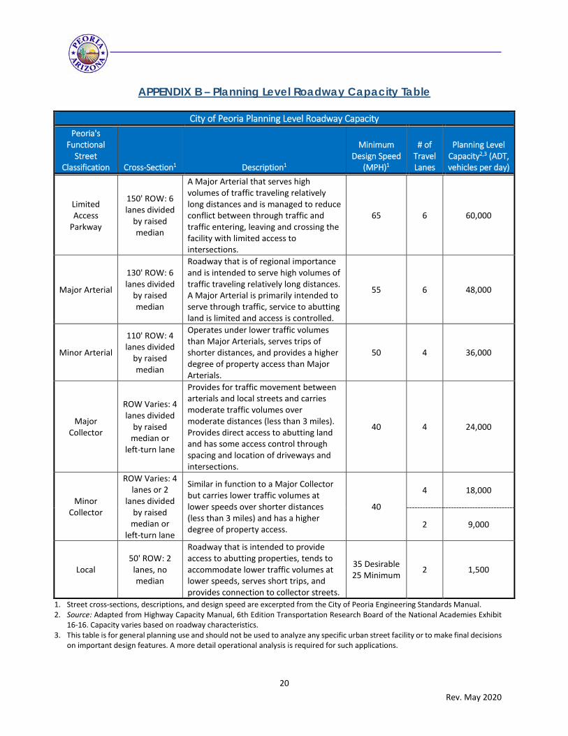
APPENDIX B – Planning Level Roadway Capacity Table
City of Peoria Planning Level Roadway Capacity Peoria's
Functional Street
Classification Cross-Section1 Description1
Minimum Design Speed
(MPH)1
# of Travel Lanes
Planning Level Capacity2,3 (ADT, vehicles per day)
Limited Access
Parkway
150' ROW: 6 lanes divided
by raised median
A Major Arterial that serves high volumes of traffic traveling relatively long distances and is managed to reduce conflict between through traffic and traffic entering, leaving and crossing the facility with limited access to intersections.
65 6 60,000
Major Arterial
130' ROW: 6 lanes divided
by raised median
Roadway that is of regional importance and is intended to serve high volumes of traffic traveling relatively long distances. A Major Arterial is primarily intended to serve through traffic, service to abutting land is limited and access is controlled.
55 6 48,000
Minor Arterial
110' ROW: 4 lanes divided
by raised median
Operates under lower traffic volumes than Major Arterials, serves trips of shorter distances, and provides a higher degree of property access than Major Arterials.
50 4 36,000
Major Collector
ROW Varies: 4 lanes divided
by raised median or
left-turn lane
Provides for traffic movement between arterials and local streets and carries moderate traffic volumes over moderate distances (less than 3 miles). Provides direct access to abutting land and has some access control through spacing and location of driveways and intersections.
40 4 24,000
Minor Collector
ROW Varies: 4 lanes or 2
lanes divided by raised
median or left-turn lane
Similar in function to a Major Collector but carries lower traffic volumes at lower speeds over shorter distances (less than 3 miles) and has a higher degree of property access.
40
4 18,000
2 9,000
Local 50' ROW: 2
lanes, no median
Roadway that is intended to provide access to abutting properties, tends to accommodate lower traffic volumes at lower speeds, serves short trips, and provides connection to collector streets.
35 Desirable 25 Minimum 2 1,500
1. Street cross-sections, descriptions, and design speed are excerpted from the City of Peoria Engineering Standards Manual. 2. Source: Adapted from Highway Capacity Manual, 6th Edition Transportation Research Board of the National Academies Exhibit
16-16. Capacity varies based on roadway characteristics. 3. This table is for general planning use and should not be used to analyze any specific urban street facility or to make final decisions
on important design features. A more detail operational analysis is required for such applications.


