TRAILER LIGHTS CONTROL UNIT MP5 INSTALLATION MANUAL
GENERAL FUNCTION DESCRIPTIONGENERAL FUNCTION DESCRIPTION
The module is designed to control the trailer lighting system.The car rear light voltages are used to drive the controller module. The module inputs should be connected to the car rear lights driving wires according to required trailer lighting driving pattern. The module inputs for correct operation require only around 1 mA each (a 5W bulb is drawing 0.5 amp) and total current consumption does not activate overload sensing modules in the car’s lighting system. The module will activate required lights on the trailer after receiving input driving signal.
The controller can also work with electric installations in the cars where some of the lights perform two light intensity functions based on PWM (pulse width modulation) technique.
The module is provided to control a lighting of the trailer through 13-pin socket used in camping trailers.
MODULE FUNCTIONSMODULE FUNCTIONS
Driving the trailer lights according to required regulations;
Dimming of the car fog light when trailer is connected (two fog light lamps handling);
Cooperation with double or single filament bulb systems or LED;
Automatic detection of a connected trailer (tested electric connection only);
Signalization of the trailer electric connection status with LED;
Parking sensor switching (turning ON/OFF);
Car alarm cooperation option (output: “Alarm Info”);
Signalization of trailer direction lights bulb failure with external LED and fast car direction lights blinking;
Powering the trailer from the car power supply;
Automatic charge of trailer battery after car engine start;
The trailer battery charge state indication by both central unit LED and external LED;
Signalization with internal buzzer the lack of trailer battery charging voltage (fuseblow).
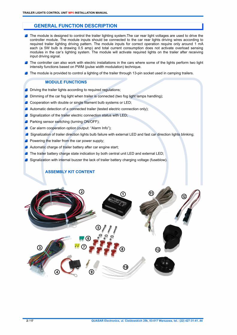
(1) Main control unit – 1 pc.(2) Trailer socket harness MP4-W10 – 1 pc.(3) Main harness MP5-W24 – 1 pc.(4) Fuse holder harness – 1 pc.(5) Mounting screw with a nut and washer – 3 pcs.(6) Fuse 30 A – 1 pc.(7) Fuse 20 A – 1 pc.(8) Fast connector – 8 pcs.(9) Connector with an insulating cover – 1 pc.(10) Cable tie – 3 pcs.(11) Supplementary harness MP5-W03-LED – 1 pc.(12) MP5-W03-RJ11 harness – 1 pc.(13) Trailer 13-pin socket with a gasket – 1 pc.
ADDITIONAL ACCESORIES
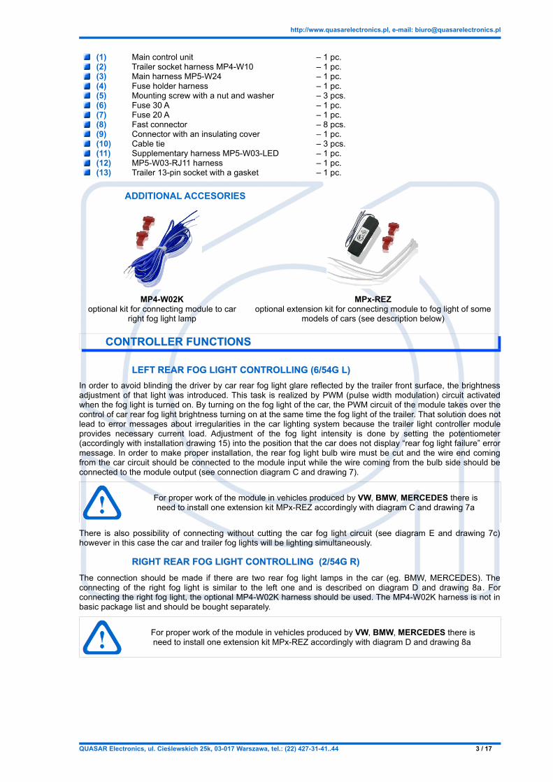
MP4-W02Koptional kit for connecting module to car
right fog light lamp
MPx-REZoptional extension kit for connecting module to fog light of some
models of cars (see description below)
CONTROLLER FUNCTIONSCONTROLLER FUNCTIONS
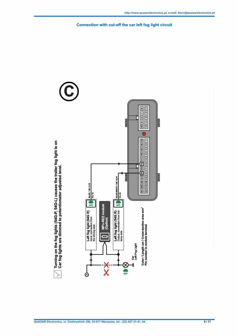
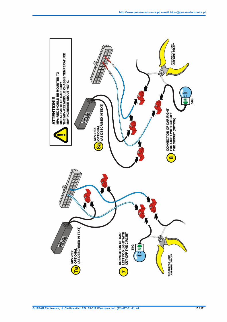
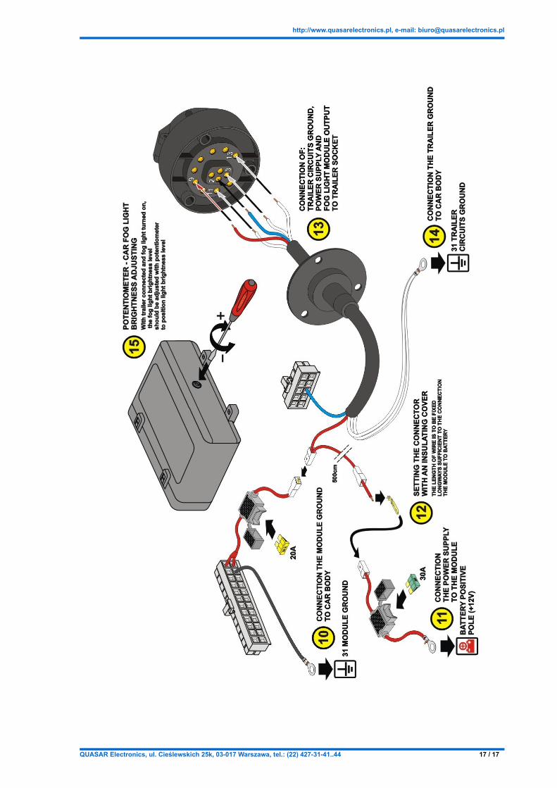
LEFT REAR FOG LIGHT CONTROLLING (6/54G L)LEFT REAR FOG LIGHT CONTROLLING (6/54G L)In order to avoid blinding the driver by car rear fog light glare reflected by the trailer front surface, the brightness adjustment of that light was introduced. This task is realized by PWM (pulse width modulation) circuit activated when the fog light is turned on. By turning on the fog light of the car, the PWM circuit of the module takes over the control of car rear fog light brightness turning on at the same time the fog light of the trailer. That solution does not lead to error messages about irregularities in the car lighting system because the trailer light controller module provides necessary current load. Adjustment of the fog light intensity is done by setting the potentiometer (accordingly with installation drawing 15) into the position that the car does not display “rear fog light failure” error message. In order to make proper installation, the rear fog light bulb wire must be cut and the wire end coming from the car circuit should be connected to the module input while the wire coming from the bulb side should be connected to the module output (see connection diagram C and drawing 7).
For proper work of the module in vehicles produced by VW, BMW, MERCEDES there is need to install one extension kit MPx-REZ accordingly with diagram C and drawing 7a
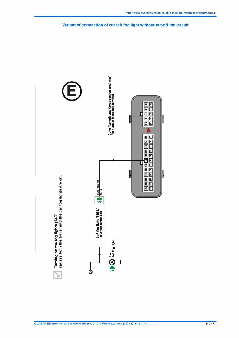
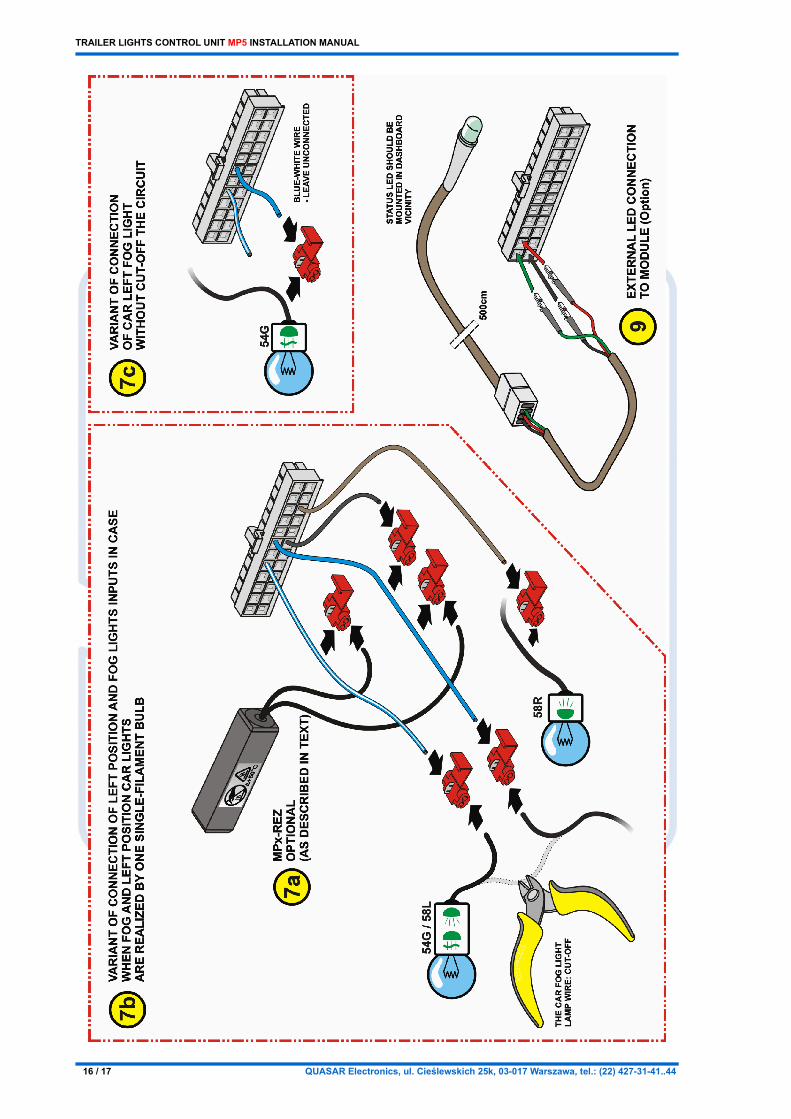
There is also possibility of connecting without cutting the car fog light circuit (see diagram E and drawing 7c) however in this case the car and trailer fog lights will be lighting simultaneously.
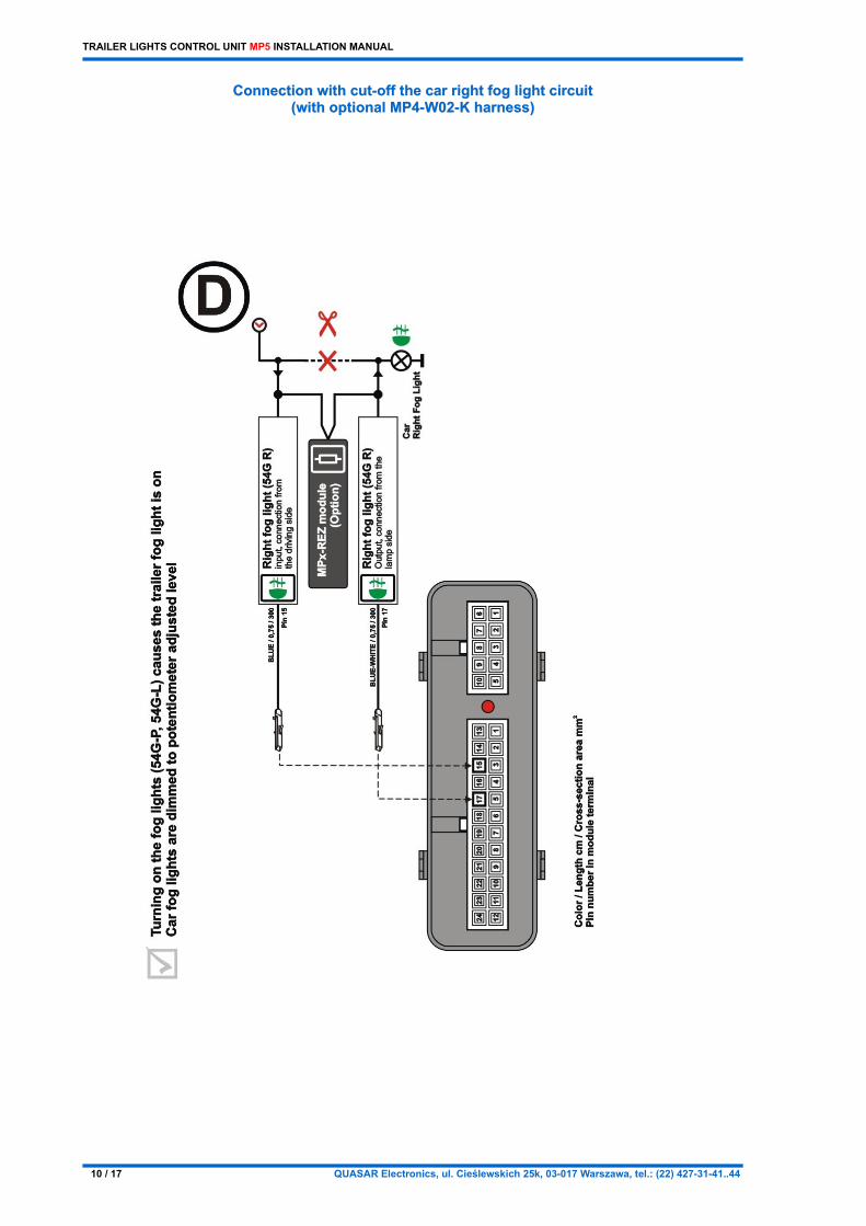
RIGHT REAR FOG LIGHT CONTROLLING (2/54G R)RIGHT REAR FOG LIGHT CONTROLLING (2/54G R)The connection should be made if there are two rear fog light lamps in the car (eg. BMW, MERCEDES). The connecting of the right fog light is similar to the left one and is described on diagram D and drawing 8a. For connecting the right fog light, the optional MP4-W02K harness should be used. The MP4-W02K harness is not in basic package list and should be bought separately.
For proper work of the module in vehicles produced by VW, BMW, MERCEDES there is need to install one extension kit MPx-REZ accordingly with diagram D and drawing 8a
TRAILER LIGHTS CONTROL UNIT MP5 INSTALLATION MANUAL
CONNECTING IN CASE OF SINGLE-FILAMENT BULB PERFORMING TWOCONNECTING IN CASE OF SINGLE-FILAMENT BULB PERFORMING TWO FUNCTIONS: POSITION AND FOG LIGHT FUNCTIONS: POSITION AND FOG LIGHT
This function is designed for the cars where the position light and rear fog light are realized on a single filament bulb (Touran, CADDY, Octavia II, Astra III, Vectra C, Signum...). The position light function is realized by applying 6V RMS voltage to the bulb. The fog light is realized by applying 12V to the same bulb. In this case of driving car lamp, the appropriate module input of position light (left or right) should be connected with appropriate fog light input (left or right). The drawing 7b describes connecting together inputs of left position light and rear left fog light. In other but similar case (right position light or right rear light) the adequate inputs should be connected.
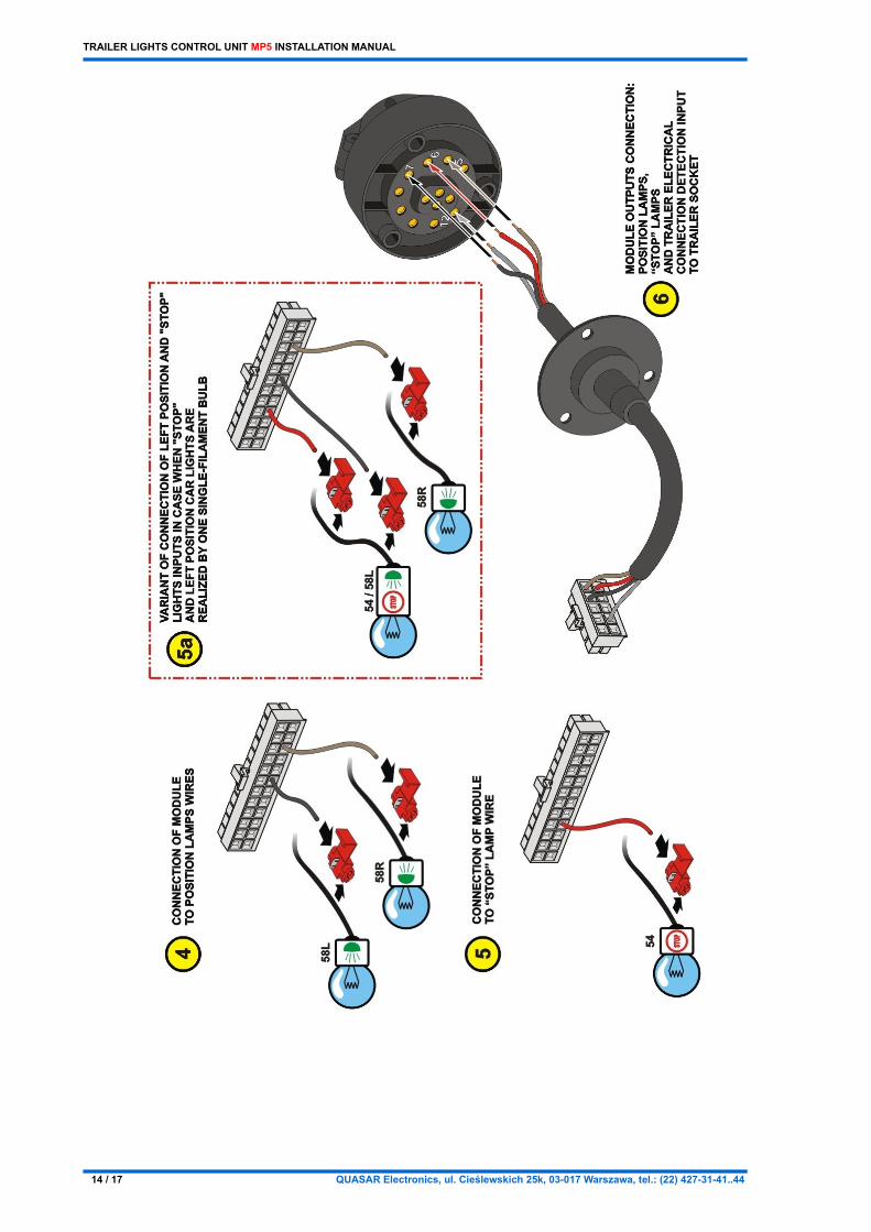
CONNECTING IN CASE OF SINGLE-FILAMENT BULB PERFORMING TWOCONNECTING IN CASE OF SINGLE-FILAMENT BULB PERFORMING TWO FUNCTIONS: POSITION AND STOP LIGHTFUNCTIONS: POSITION AND STOP LIGHT
This function is designed for the cars where the position light and stop light are realized on a single filament bulb. The position light function is realized by applying 6V RMS voltage to the bulb. The stop light is realized by applying 12V to the same bulb. In this case of driving car lamp, the appropriate module input of position light (left or right) should be connected with stop light input. The drawing 5a describes connecting together inputs of left position light and stop light. In other but similar case (right position light) the adequate inputs should be connected.
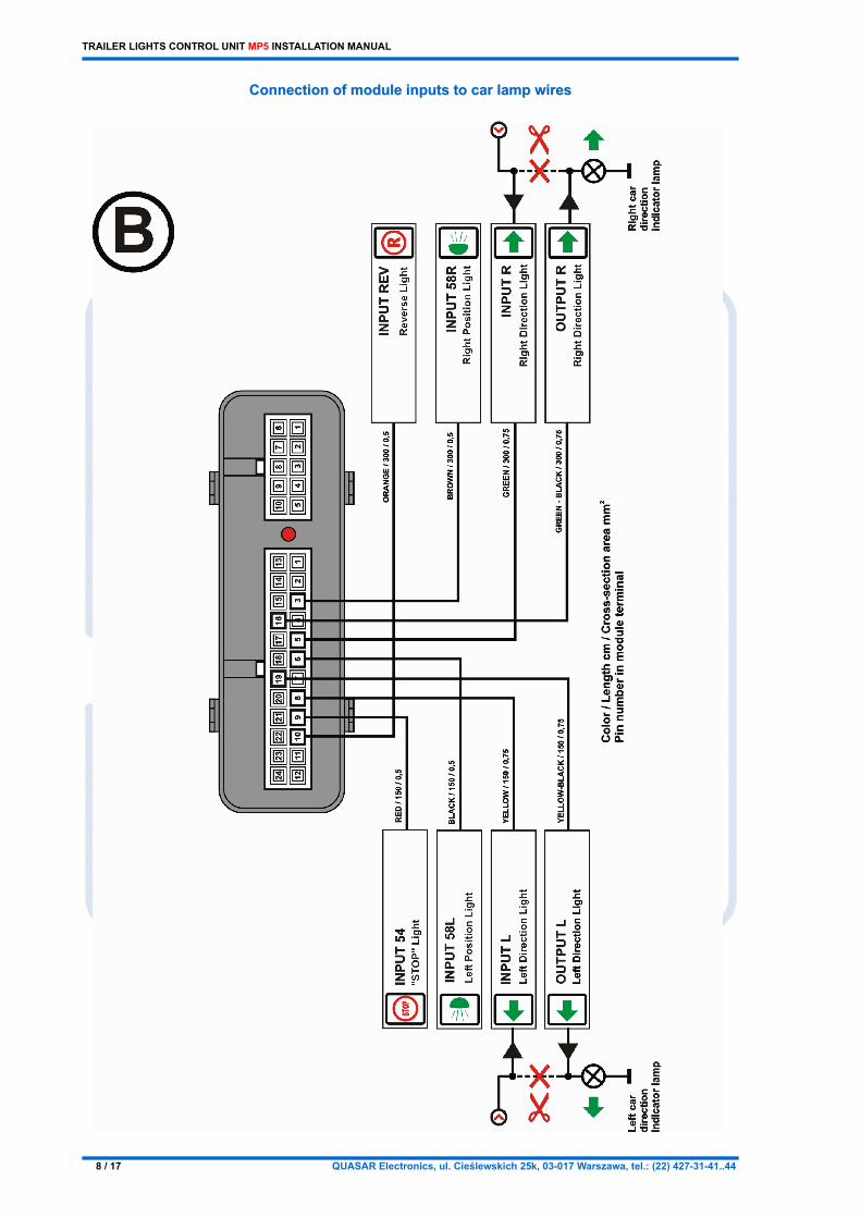
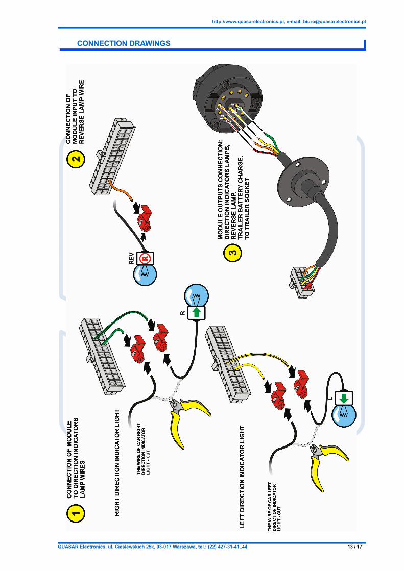
DIRECTION LIGHTS CONNECTINGDIRECTION LIGHTS CONNECTINGIn MP5 version there is applied additional function informing that the one of direction lights bulb is broken similarly as the car direction lighs bulb breakage is indicated. When the car direction lights bulb is broken, the direction lights blink about two times quicker. In case of breaking the trailer direction lights bulb, the module "simulates" breaking of car direction lights bulb wherethrough the same "quicker blinking" effect is achieved. This function is required by low in some European countries. In this case, the module is connected with cutting the car rear direction lights wires accordingly with installation schematic B and connection drawing 1.
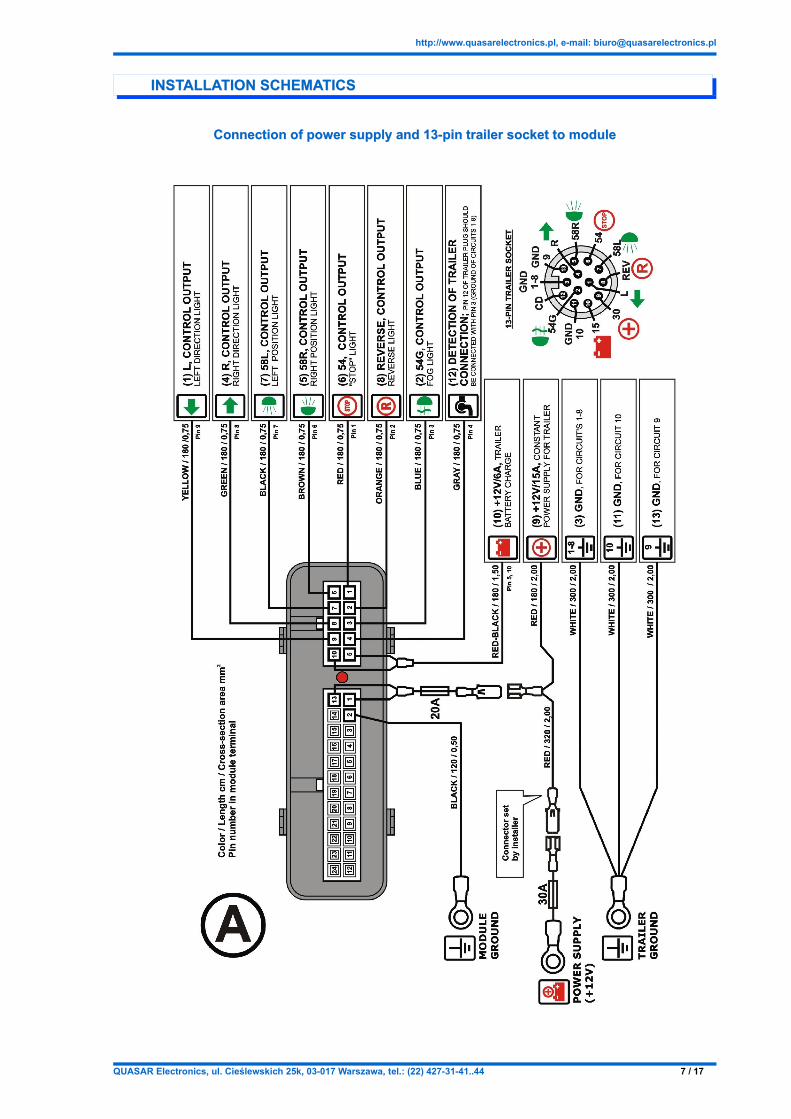
TEST OF TRAILER ELECTRICAL CONNECTION AND DISCONNECTIONTEST OF TRAILER ELECTRICAL CONNECTION AND DISCONNECTIONIndependently of trailer socket Pin 12 function ("trailer connected"), test of trailer electrical connection is provided through checking if the trailer stop light bulbs are connected. The bulb filaments perform as a sensor for the testing circuit. Minimal power load for proper work is 10 Watt. Pin 12 of the trailer plug should be connected to ground (Pin 3).
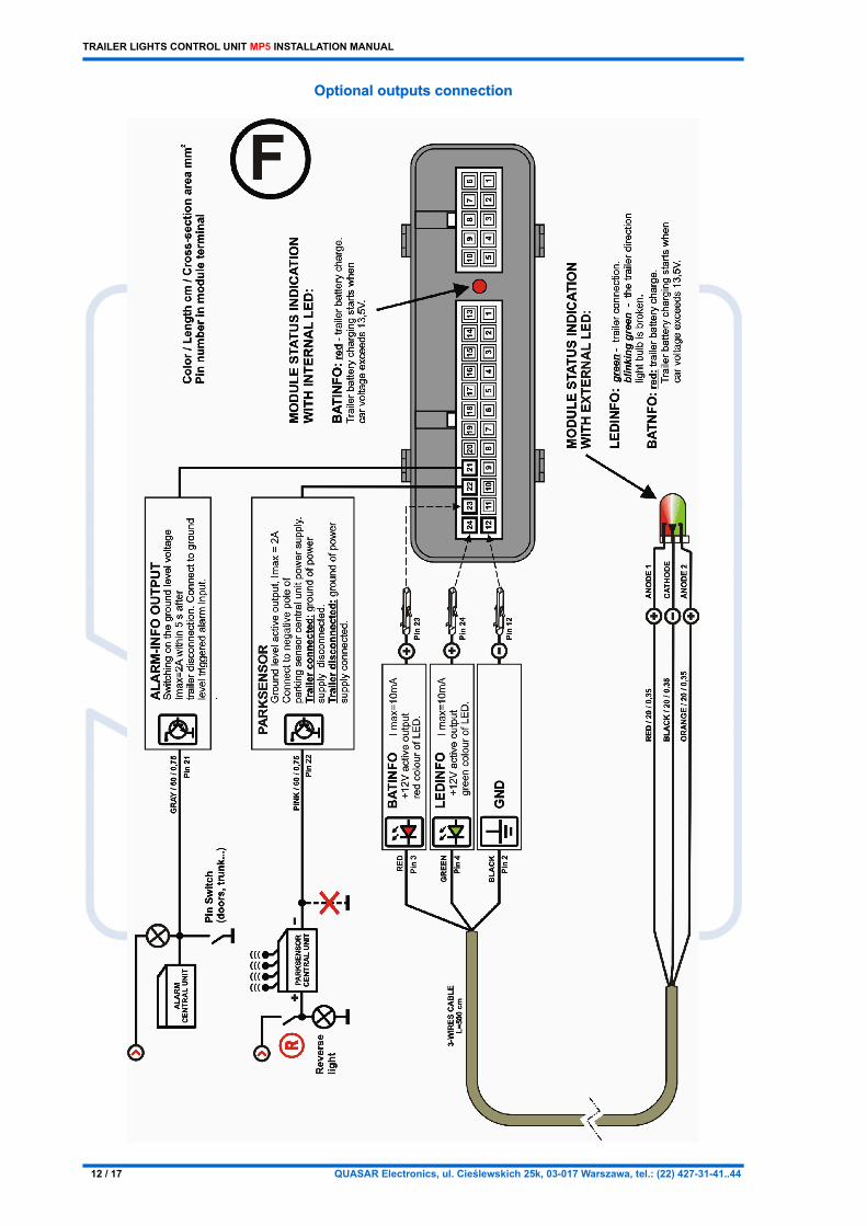
CAR ALARM INTEROPERABILITYCAR ALARM INTEROPERABILITYThe control unit detects whether the trailer is unplugged and after approx. 1 second activate output "Alarm Info" setting it for approx. 1 second to ground level (max. 2A). This output can be connected to an existing car alarm or GPS monitoring. For example, this output could be connected to the door, hood or trunk switch, the ground level pulse will simulate the switch activation and trigger the alarm.
PARKING SENSORS INTEROPERABILITYPARKING SENSORS INTEROPERABILITYIn the cars, where the ultrasonic parking sensors without “permanent obstacle” learning function are installed (the trailer becomes a permanent obstacle), the sensors can be blocked for the time when the trailer is plugged in. The module has a current output (max. load 2A) which connects to GROUND when the trailer is unplugged. Detection of trailer connection causes that the GROUND level will be disconnected on that output. This output could be used to powering the ultrasonic sensor control unit providing the ground level to it.
POWERING THE TRAILER FROM THE CAR POWER SUPPLYPOWERING THE TRAILER FROM THE CAR POWER SUPPLYThe module enables powering the trailer from the car power supply. Maximum current load of the Pin 9 of trailer socket is 15 A.
TRAILER BATTERY CHARGETRAILER BATTERY CHARGEThe module provides trailer battery charge after the car engine starts. The car engine start is implicated when car battery voltage is above 13,4V. The trailer battery charging will be stopped when car installation voltage is below 13V (the car engine stop working). The maximum current load of the Pin 10 of trailer socket is 6 A.
LED-INFO STATUS OUTPUTLED-INFO STATUS OUTPUTThe double-color LED connected to this output displays the following states:
LED Module status
Off Trailer unplugged electrically
Continuous green Trailer electrically connected
Flashes green One of the direction lights bulb is broken
Continuous red Trailer battery charge switched on (when car installation voltage is above 13,4 V).
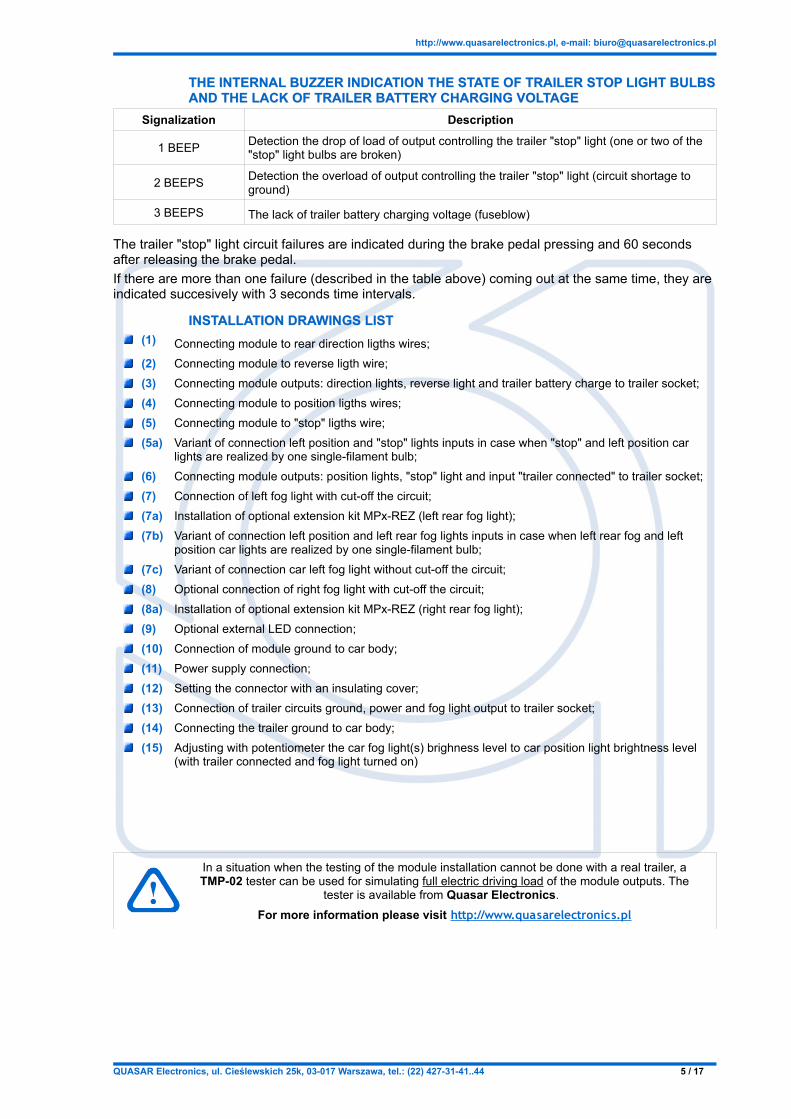
THE INTERNAL BUZZER INDICATION THE STATE OF TRAILER STOP LIGHT BULBSTHE INTERNAL BUZZER INDICATION THE STATE OF TRAILER STOP LIGHT BULBS AND THE LACK OF TRAILER BATTERY CHARGING VOLTAGEAND THE LACK OF TRAILER BATTERY CHARGING VOLTAGE
Signalization Description
1 BEEP Detection the drop of load of output controlling the trailer "stop" light (one or two of the "stop" light bulbs are broken)
2 BEEPS Detection the overload of output controlling the trailer "stop" light (circuit shortage to ground)
3 BEEPS The lack of trailer battery charging voltage (fuseblow)
The trailer "stop" light circuit failures are indicated during the brake pedal pressing and 60 seconds after releasing the brake pedal.If there are more than one failure (described in the table above) coming out at the same time, they are indicated succesively with 3 seconds time intervals.
INSTALLATION DRAWINGS LISTINSTALLATION DRAWINGS LIST(1) Connecting module to rear direction ligths wires;(2) Connecting module to reverse ligth wire;(3) Connecting module outputs: direction lights, reverse light and trailer battery charge to trailer socket;(4) Connecting module to position ligths wires;(5) Connecting module to "stop" ligths wire;(5a) Variant of connection left position and "stop" lights inputs in case when "stop" and left position car
lights are realized by one single-filament bulb;(6) Connecting module outputs: position lights, "stop" light and input "trailer connected" to trailer socket;(7) Connection of left fog light with cut-off the circuit;(7a) Installation of optional extension kit MPx-REZ (left rear fog light);(7b) Variant of connection left position and left rear fog lights inputs in case when left rear fog and left
position car lights are realized by one single-filament bulb;(7c) Variant of connection car left fog light without cut-off the circuit;(8) Optional connection of right fog light with cut-off the circuit;(8a) Installation of optional extension kit MPx-REZ (right rear fog light);(9) Optional external LED connection;(10) Connection of module ground to car body; (11) Power supply connection;(12) Setting the connector with an insulating cover;(13) Connection of trailer circuits ground, power and fog light output to trailer socket;(14) Connecting the trailer ground to car body;(15) Adjusting with potentiometer the car fog light(s) brighness level to car position light brightness level
(with trailer connected and fog light turned on)
In a situation when the testing of the module installation cannot be done with a real trailer, a TMP-02 tester can be used for simulating full electric driving load of the module outputs. The
tester is available from Quasar Electronics. For more information please visit http://www.quasarelectronics.pl
TRAILER LIGHTS CONTROL UNIT MP5 INSTALLATION MANUAL
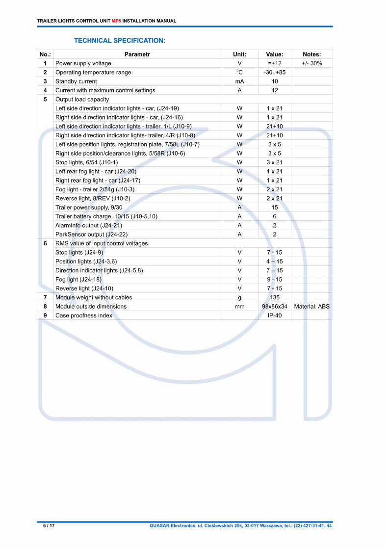
TECHNICAL SPECIFICATION:TECHNICAL SPECIFICATION:
No.: Parametr Unit: Value: Notes:1 Power supply voltage V =+12 +/- 30%2 Operating temperature range 0C -30..+853 Standby current mA 104 Current with maximum control settings A 125 Output load capacity
Left side direction indicator lights - car, (J24-19)Right side direction indicator lights - car, (J24-16)Left side direction indicator lights - trailer, 1/L (J10-9)
WWW
1 x 211 x 2121+10
Right side direction indicator lights- trailer, 4/R (J10-8) W 21+10Left side position lights, registration plate, 7/58L (J10-7) W 3 x 5Right side position/clearance lights, 5/58R (J10-6) W 3 x 5Stop lights, 6/54 (J10-1) W 3 x 21Left rear fog light - car (J24-20) W 1 x 21Right rear fog light - car (J24-17) W 1 x 21Fog light - trailer 2/54g (J10-3) W 2 x 21Reverse light, 8/REV (J10-2) W 2 x 21Trailer power supply, 9/30 A 15Trailer battery charge, 10/15 (J10-5,10) A 6AlarmInfo output (J24-21) A 2ParkSensor output (J24-22) A 2
6 RMS value of input control voltagesStop lights (J24-9) V 7 - 15Position lights (J24-3,6) V 4 – 15Direction indicator lights (J24-5,8) V 7 – 15Fog light (J24-18) V 9 - 15Reverse light (J24-10) V 7 - 15
7 Module weight without cables g 1358 Module outside dimensions mm 98x86x34 Material: ABS9 Case proofness index IP-40
TRAILER LIGHTS CONTROL UNIT MP5 INSTALLATION MANUAL
Connection with cut-off the car right fog light circuitConnection with cut-off the car right fog light circuit(with optional MP4-W02-K harness)(with optional MP4-W02-K harness)