44
AS 7708:2016 Signals Earthing and Surge Protection Train Control Systems Standard Open Consultation Draft for Comment

AS 7708:2016
S i g n a l s E a r t h i n g a n d S u r g eP r o t e c t i o n
Train Control Systems Standard
Open Consultation
Draft for Comment

AS 7708:2016
Signals Earthing and Surge Protection
RISSB ABN 58 105 001 465 Page 2 Accredited Standards Development Organisation
This Australian Standard® AS 7708 Signals Earthing and Surge Protection was prepared by a RISSB Development Group consisting of representatives from the following organisations: Click here to enter the organisations represented on the Development Group. Tab between them. The Standard was approved by the Development Group and the Enter Standing Committee Standing Committee in Select SC approval date. On Select Board approval date the RISSB Board approved the Standard for release. Choose the type of review Development of the standard was undertaken in accordance with RISSB’s accredited process. As part of the approval process, the Standing Committee verified that proper process was followed in developing the standard. RISSB wishes to acknowledge the positive contribution of subject matter experts in the development of this standard. Their efforts ranged from membership of the Development Group through to individuals providing comment on a draft of the standard during the open review. I commend this standard to the Australasian Rail Industry as it represents industry good practice and has been developed through a rigorous process.
Paul Daly Chief Executive Officer Rail Industry Safety and Standards Board
Keeping Standards up-to-date Australian Standards developed by RISSB are living documents that reflect progress in science, technology and systems. To maintain their currency, Standards are reviewed every seven years, and new editions are published. Between editions, amendments may be issued. Australian Standards developed by RISSB may also be withdrawn. It is important that readers assure themselves they are using a current RISSB Standard, which should include any amendments that may have been issued since the Standard was published. Information about Australian Standards developed by RISSB, including amendments, can be found by visiting www.rissb.com.au RISSB welcomes suggestions for improvements, and asks readers to notify us immediately of any apparent inaccuracies or ambiguities. Members are encouraged to use the change request feature of the RISSB website at: http://www.rissb.com.au/products/. Otherwise, please contact us via email at [email protected] or write to Rail Industry Safety and Standards Board, PO Box 4271, Kingston, ACT 2604.
Open Consultation
Draft for Comment

AS 7708:2016
Signals Earthing and Surge Protection
RISSB ABN 58 105 001 465 Page 3 Accredited Standards Development Organisation
AS 7708: 2016
Signals Earthing and Surge Protection
Document Details First published as: Enter first publication title/s ISBN Enter ISBN. Published by Rail Industry Safety and Standards Board (RISSB) ABN: 58 105 001 465 PO Box 4271, Kingston, ACT, Australia 2604
Copyright ©RISSB All rights are reserved. No part of this work may be reproduced or copied in any form or by any means, electronic or mechanical, including photocopying, without the written permission of RISSB, unless otherwise permitted under the Copyright Act 1968.
Notice to Users This RISSB product has been developed using input from rail experts from across the rail industry and represents good practice for the industry. The reliance upon or manner of use of this RISSB product is the sole responsibility of the user who is to assess whether it meets their organisation’s operational environment and risk profile.
Open Consultation
Draft for Comment

AS 7708:2016
Signals Earthing and Surge Protection
RISSB ABN 58 105 001 465 Page 4 Accredited Standards Development Organisation
Document Control
Identification
Document Title
AS 7708:2016 Signals Earthing and Surge Protection
Document History
Publication Version Effective Date Reason for and Extent of Change(s)
2016 Select Board approval date
Draft History
Publication Version Effective Date Reason for and Extent of Change(s)
Version 1.0 03 May 2016 Development of Headings/Index
Version 1.1 18 July 2016 Preliminary Draft Standard Issued to RISSB
Version 1.2 07 September 2016 Draft Standard Issued to RISSB (Open Consultation)
Approval
Name Date
Rail Industry Safety and Standards Board (RISSB) Select Board approval date
Open Consultation
Draft for Comment

AS 7708:2016
Signals Earthing and Surge Protection
RISSB ABN 58 105 001 465 Page 5 Accredited Standards Development Organisation
Contents 1 Introduction ................................................................................................................... 9
1.1 Purpose .......................................................................................................... 9 1.2 Scope ............................................................................................................. 9 1.3 Compliance ................................................................................................... 10 1.4 Referenced documents ................................................................................. 10
Normative references .................................................................................... 10 Informative references .................................................................................. 12 Definitions ..................................................................................................... 12 Acronyms ...................................................................................................... 13
2 General ...................................................................................................................... 15 2.1 Principles ...................................................................................................... 15 2.2 Safety ........................................................................................................... 15
Functional safety ........................................................................................... 15 Work health and safety ................................................................................. 15
2.3 Competency requirements ............................................................................ 15 2.4 Change management ................................................................................... 15 2.5 Interface coordination ................................................................................... 16 2.6 Documentation and record management ...................................................... 16
Quality assurance ......................................................................................... 16 Quality assurance documentation ................................................................. 16
2.7 Verification and validation ............................................................................. 16 2.8 Risk management ......................................................................................... 16 2.10 Life ................................................................................................................ 17
3 Design and Development ........................................................................................... 17 3.1 Design management plan ............................................................................. 17 3.2 Safety in design ............................................................................................ 17 3.3 Selection criteria ........................................................................................... 17
Equipment Location ...................................................................................... 17 Types of railway signalling equipment requiring protection ............................ 18 Surges .......................................................................................................... 18
3.4 Design considerations ................................................................................... 18 Lightning Surges ........................................................................................... 19 Earthing arrangement ................................................................................... 19 Earth Potential Rise (EPR) ............................................................................ 20 Earth Resistance .......................................................................................... 20 Separation of earth's system ......................................................................... 21 Protective safety earth and bonding .............................................................. 21 Protection performance ................................................................................. 22 Protection zones ........................................................................................... 23 Clean and dirty wiring segregation ................................................................ 23
Open Consultation
Draft for Comment

AS 7708:2016
Signals Earthing and Surge Protection
RISSB ABN 58 105 001 465 Page 6 Accredited Standards Development Organisation
Reliability Availability and Maintainability (RAM) ........................................... 23 Adjacent structures ....................................................................................... 24 Multiple Earth Neutral ................................................................................... 24 Step and touch potential ............................................................................... 24 Test points .................................................................................................... 24
3.5 Earthing connections .................................................................................... 25 3.6 Earth Leakage Detector ................................................................................ 25
Earth Leakage Detector sensitivity ................................................................ 25 3.7 Signalling system availability risk and possible solutions............................... 25
Failure Mode and Effect Analysis (FMEA) ..................................................... 26 3.8 Dimensions ................................................................................................... 26 3.9 Documentation of earth wires ....................................................................... 26 3.10 Type approval requirements ......................................................................... 26
4 Construction and Implementation ............................................................................... 26 4.1 Detailed requirements ................................................................................... 26 4.2 Factors to be considered............................................................................... 26
Safety integrity of inter-connections .............................................................. 27 Interface coordination ................................................................................... 27 Signalling system availability risk and possible solution ................................ 27 Accessibility and maintainability .................................................................... 27 Wiring separation and cable routing .............................................................. 27
4.3 Cables .......................................................................................................... 28 4.4 Verification and Validation ............................................................................. 28 4.5 Records and Documentation ......................................................................... 29
Labelling ....................................................................................................... 29 4.6 Worker safety risks ....................................................................................... 29
5 Testing and Commissioning ....................................................................................... 29 5.1 General ......................................................................................................... 29 5.2 Inspection and test plans .............................................................................. 30
Earth system resistance testing .................................................................... 30 Testing of safety integrity of inter-connections: ............................................. 30 System availability risk and management ..................................................... 30
5.3 Testing documentation .................................................................................. 30 6 Monitoring and Maintenance ...................................................................................... 31
6.1 Maintainability ............................................................................................... 31 Periodic examination ..................................................................................... 31 Performance monitoring ................................................................................ 31
6.2 Failure modes and indicators ........................................................................ 31 7 Modification ................................................................................................................ 31
7.1 Configuration management ........................................................................... 31 7.2 Risk management ......................................................................................... 32
Open Consultation
Draft for Comment

AS 7708:2016
Signals Earthing and Surge Protection
RISSB ABN 58 105 001 465 Page 7 Accredited Standards Development Organisation
8 Decommissioning and Disposal .................................................................................. 32 8.1 General ......................................................................................................... 32 8.2 Decommissioning.......................................................................................... 32 8.3 Disposal ........................................................................................................ 33
Open Consultation
Draft for Comment

AS 7708:2016
Signals Earthing and Surge Protection
RISSB ABN 58 105 001 465 Page 8 Accredited Standards Development Organisation
Appendix Contents Appendix A Equipment Classification ............................................................................... 34 Appendix B Principles of Equipotential Bonding ............................................................... 35
B.1 Principles of Equipotential Bonding ............................................................... 35 B.2 Methods of equipotential bonding ................................................................. 35 B.3 Signalling Equipment room ........................................................................... 36
Appendix C Zone Concept ............................................................................................... 38 Appendix D Separation criteria ......................................................................................... 39 Appendix E Lightning protection for railway signalling ...................................................... 40
Tables Table 1. Earth Resistance Requirements………………………………………………………... 21 Table 2. Earth Leakage Detector Sensitivity Settings……………………………………….…. 21 Table 3. Equipment Types used in the Railway Signalling Infrastructure…………………….. 34 Table 4. Absolute separation distance (includes wiring crossing at right angles)………….... 39 Table 5. Separation distance for more than 1 metre of parallelism………………………….... 39
Open Consultation
Draft for Comment

AS 7708:2016
Signals Earthing and Surge Protection
RISSB ABN 58 105 001 465 Page 9 Accredited Standards Development Organisation
1 Introduction
1.1 Purpose This Standard describes a set of mandatory and recommended requirements for the nomenclature, design and development, construction and implementation, testing and commissioning, monitoring and maintenance, modification, decommissioning and disposal of signals earthing and surge protection in Australia. The main purpose of the requirements are to:
Provide a uniform basis to address all identified hazards associated with lightning and electrical surges in railway signalling and telecommunications equipment.
Clearly and accurately describe each of the essential requirements (functions, design considerations and constraints, performance, maintainability, monitoring and safety) of signals earthing and surge protection devices for railway application.
Promote a consistent or uniform treatment of signals earthing and surge protection methods across the Australian railway networks.
1.2 Scope This Standard provides a whole-of-life cycle approach to safety application of signals earthing and surge protection devices. It covers the general management requirements, design and development, construction and implementation, testing and commissioning, monitoring and maintenance, modification, decommissioning and disposal of signals earthing and surge protection devices in Australian railnetworks. The following are covered under this standard:
• Lightning surges;
• Traction surges
• Power surges;
• Earth potential rise from power system faults;
• Worker safety risk;
• Signalling system availability risk and possible solutions;
• Computer and data communications system interface;
• Standard requirements for products;
• Signals earthing requirements;
• Earthing, communications, traction coordination;
• Earth wiring within location / earth impedance;
• Electric traction drop zone and protection;
• Ongoing maintenance;
• Adjacent power lines;
• Clean and dirty wiring segregation;
Open Consultation
Draft for Comment

AS 7708:2016
Signals Earthing and Surge Protection
RISSB ABN 58 105 001 465 Page 10 Accredited Standards Development Organisation
• Standard requirements for surge protection devices & earthing equipment;
• Dimensions;
• Test points;
• Connections;
• Safety integrity of cross connections;
• Indexing of components;
• Fail indicators;
• Failure modes;
• Multiple earthing situations;
• Condition monitoring and remote monitoring. This standard does not cover electrical traction bonding for worker protection.
1.3 Compliance There are two types of control contained within RISSB Standards:
mandatory requirements recommended requirements
Each of these types of control address hazards that are deemed to require controls on the basis of existing Australian and international Codes of Practice and Standards. A mandatory requirement is a requirement that the standard provides as the only way of treating the hazard. Mandatory requirements are identified within the text by the term shall. A recommended requirement is one where the standard recognises that there are limitations to the universal application of the requirement and that there may be circumstances where the control cannot be applied or that other controls may be appropriate or satisfactory, subject to agreement with the Rolling Stock Operator, Rail Infrastructure Manager and/or Rail Safety Regulator. Recommended clauses are mandatory unless the RIM or RSO can demonstrate a better method of controlling the risk. Recommended requirements are to be considered when compliance with the standards is being assessed. Recommended requirements are identified within the text by the term should. Hazards addressed by this standard are included in an Appendix. Refer to the RISSB website for the latest Hazard Register Guideline: www.rissb.com.au
1.4 Referenced documents
Normative references The following referenced documents are indispensable for the application of this Standard:
AS4292.1 – Railway safety general requirements
Open Consultation
Draft for Comment

AS 7708:2016
Signals Earthing and Surge Protection
RISSB ABN 58 105 001 465 Page 11 Accredited Standards Development Organisation
AS4292.4 – Signalling and telecommunications systems and equipment AS7702 – Type Approval Standard AS7720 – Signals Enclosure AS7722 – EMC Management AS/CA S009 – Australian Standard – Installation requirements for customer
cabling (Wiring Rules) AS/ISO 9000.2 – Quality Management and Quality Assurance Standards AS/ISO 9001 – Quality Management Systems – Requirements AS/ISO 9004 – Quality Management Systems – Guidelines for Performances
AS/NZS 1768 – Lightning protection AS/NZS 3000 – Wiring rules Section 5 – Earthing arrangement and earthing
conductors AS/NZS 4117 – Surge protective devices for telecommunications applications AS/NZS ISO 31000 – Risk Management - principles and guidelines Work Health and Safety Acts and Regulations Rail Safety National Law and Regulations AS/NZS IEC 60300 - Dependability Management - Guidance for management
and application IEC61643-11 Low Voltage surge protective devices - Part 11: Surge protective
devices connected to low-voltage power systems - Requirements and test method
IEC 61643 -12 Low Voltage surge protective devices - Part 12: Surge protective devices connected to low-voltage power systems - Selection and application principles
IEC 61643 -21 Low Voltage surge protective devices - Part 21: Surge protective devices connected to telecommunications and signalling networks - Performance requirements and testing methods
IEC 61643 -22 Low Voltage surge protective devices - Part 22: Surge protective devices connected to telecommunications and signalling networks -Selection and application principles
IEC 62236-4: Railway applications - Electromagnetic compatibility - Part 4: Emission and immunity of the signalling and telecommunications apparatus
IEC 62236-4: Railway applications - Electromagnetic compatibility - Part 4: Emission and immunity of power supply installations and apparatus
IEC 62498-3 - Railway applications - Environmental conditions for equipment - Part 3: Equipment for signalling and telecommunications
IEC 62561 - 7 Lightning protection system components (LPSC) - Part 7: Requirements for earthing enhancing compounds
IEC 6305:2013 SER Protection against lightning - ALL PARTS
Open Consultation
Draft for Comment

AS 7708:2016
Signals Earthing and Surge Protection
RISSB ABN 58 105 001 465 Page 12 Accredited Standards Development Organisation
IEEE 837:2014 Qualifying Permanent Connections Usedin Substation Grounding
Informative references The following referenced documents are used by this Standard for information only:
RISSB Guideline - Railway Infrastructure –Hazard RISSB National Guideline – Glossary of Railway Terminology
Definitions General railway technical terms can be referred to the "National Guideline - Glossary of Railway Terminology". Specific terms used in this Standard (including those drawn from the Glossary) are defined below: Apparatus case: A housing which is intended for unprotected outdoor use. It is usually of metal construction (or wooden if a cupboard), smaller than a fixed or relocatable equipment building and usually capable of being transported as a made-up unit. Category A pulse: A test surge pulse as defined in AS 1768.
Category B pulse: A test surge pulse as defined in AS 1768. Category C pulse: A test surge pulse as defined in AS 1768. Clean wiring: all cables that originate from surge or transient protection units.
Differential earth clamp: a device that electrically connects two earthing systems under transient overvoltage conditions, but remains electrically disconnected under normal operating conditions. [AS/CA S2009] Dirty wiring: All wiring from and to the field that does not have any form of surge or transient protection. Earth: The conducting mass of the ground; the process of directly connecting to an earth mat, or earth rod. [ESG-007] (This could be added to the RISSB Glossary) Earth Leakage Detector (ELD): An instrument for indicating electrical current leakage from a normally isolated circuit to earth. . [ESG-007] Earth Potential Rise (EPR): A rise in voltage of an earthing system and the surrounding soil with respect to a distant earth. EPR is a condition caused by the flow of power system fault current to earth at an HV installation such as an electrical substation, HV transformer or, commonly, an HV pole with a conductive element to earth. [AS/CA S009] Earth Rod: A metal rod with earth wire connection to disperse current into the ground for safety. [ESG-007] Earthing: Earthing of signalling equipment to protect staff from high voltage power supplies and electrification systems and to assist in protecting equipment from lightning. Signalling circuits are insulated/isolated from earth and the presence of any earth fault on wiring is a definite danger to signalling circuitry and calls for protective measures to be taken. [ESG-007] Earthing conductor: A conductor connecting any portion of the earthing system to the portion of the installation or equipment required to be earthed, or to any other portion of the earthing system. [ESG-007]
Open Consultation
Draft for Comment

AS 7708:2016
Signals Earthing and Surge Protection
RISSB ABN 58 105 001 465 Page 13 Accredited Standards Development Organisation
Earthing electrodes (earth rods or ground rods): Those portions of the earth termination that make direct low resistance electrical contact with the earth. [AS/NZS 1768:2007] Electronic equipment: An equipment that has more than 5% of its electrical parts as electronic components. Electronic components are considered to be semi-conductor based devices, and capacitors. [SPG 0712] (This could be added to the RISSB Glossary) Electro-mechanical equipment: An equipment that primarily contains inductors, electric motors, solenoids, relays, contactors, switches, resistors, etc. [SPG 0712] Electrical equipment: An equipment considered to be either Electronic equipment or Electro-mechanical equipment. If there is any doubt as to the type of a particular item of equipment then it will be considered to be electronic equipment. [SPG 0712] Equipment earth: An earth provided to an item of equipment for shielding or purposes other than surge protection. [SPG 0712] Equipotential bonding: electrical connections intended to bring exposed conductive parts or extraneous conductive parts to the same or approximately the same potential, but not intended to carry current in normal service. [AS/NZS 3000] Extra Low Voltage (ELV): a voltage not exceeding 50V AC or 120V D.C. [AS/NZS 3000]
High Voltage (HV): a voltage exceeding LV limits. [AS/NZS 3000] Low Voltage (LV): a voltage exceeding ELV limits but not exceeding 1000 V A.C. or 1500 V D.C. [AS/NZS 3000] Protection earth: An earth provided for lightning and surge protection purposes. [SPG 0712] Self-restoring: The ability to either recovers completely or in a degraded state its insulating properties after a disruptive discharge caused by the application of an overvoltage. Surge: A transient electrical overload condition due to external influences. A surge includes overloads and transient conditions due to lightning, power supply switching, and fault conditions appearing at interfaces. [SPG 0712] Surge protection: Equipment and systems for protecting electrical operating systems from transient electrical overload conditions due to external influences such as lightning, power supply switching, fault conditions. [ESG-007] Surge protective device: a device intended to limit transient overvoltages and divert surge currents. It contains at least one non-linear voltage limiting component. [IEC 61643-1]
Transient earth clamp: Also known as a differential earth clamp. It is used to limit the potential difference between two separate earths. [SPG-0712]
Acronyms AC: Alternating Current AEB: Arrestor Earth bar
CBI: Computer Based Interlocking DC: Direct Current
ELD: Earth Leakage Detector ELV: Extra Low Voltage EMC: Electromagnetic Compatibility
Open Consultation
Draft for Comment

AS 7708:2016
Signals Earthing and Surge Protection
RISSB ABN 58 105 001 465 Page 14 Accredited Standards Development Organisation
EMI: Electromagnetic Interference EPR: Earth Potential Rise
HV: High Voltage LV: Low Voltage MEBS: Main Equipotential Bonding Strip RIM: Rail Infrastructure Manager SER: Signalling Equipment Room
SPD: Surge Protection Device
Open Consultation
Draft for Comment

AS 7708:2016
Signals Earthing and Surge Protection
RISSB ABN 58 105 001 465 Page 15 Accredited Standards Development Organisation
2 General
2.1 Principles The lightning protection system shall comply with the requirements of IEC62305:2013 SER and AS/NZS 1768
2.2 Safety
Functional safety The railway signalling system is a safety system. Care must be taken to ensure that the surge protection provided cannot create an alternative path between items of signalling equipment as this may cause a significant hazard to personnel and property. The lightning and surge protection must be considered as part of the “Fail-Safe” signalling system. The surge protection equipment must not reduce the level of safety provided by the signalling system.
Work health and safety The design, manufacturing, construction, testing, commissioning, maintenance and monitoring shall comply with the relevant Rail Safety National Law and Regulations, the “Work Health and Safety Act and Regulations. The weight of the equipment shall be considered with regards to the current “Work Health and Safety Regulations & Codes of Practice” with regards to safe handling by persons and with respect to the installation and maintenance requirements. The surge protection equipment shall present a low risk to personnel working near the surge protection equipment if a nearby lightning strike occurs. The safety of personnel working on or near the surge protective equipment shall be considered when designing the layout of the surge protective equipment or the route for earth conductors.
2.3 Competency requirements The design, installation, construction, testing, commissioning, monitoring and maintenance of all signal earthing and surge protection devices shall be carried out by a staff deemed competent and suitably qualified to undertake that work in accordance with the competency management procedures established by the Rail Infrastructure Manager (RIM). Rail organisations should document each training requirement and associated competency certification relevant to perform each type of work on all railway signalling infrastructure.
2.4 Change management The RIM shall ensure that change management procedures for lightning and surge protection equipment are established by all relevant stakeholders, to ensure proper identification and control of the safety risks associated with changes to the equipment.
Open Consultation
Draft for Comment

AS 7708:2016
Signals Earthing and Surge Protection
RISSB ABN 58 105 001 465 Page 16 Accredited Standards Development Organisation
2.5 Interface coordination Coordination between disciplines shall be established to enable to identification of adjacent conductive structures and its potential impacts on propagation surges from 'ground zero' over long distances to trackside signalling equipment. This should be carried out early on in the design stage to enable the mitigation of the identified risks.
2.6 Documentation and record management
Quality assurance The design, manufacturing, construction, testing, commissioning, maintenance and monitoring of signals earthing and surge protection devices shall be accredited to the appropriate Australian Quality Standards or recognised international equivalent if the manufacturer is based overseas. It is considered that the following are appropriate Australian Quality Standards:
- AS/ISO 9001 - Quality Management Systems – Requirements - AS/ISO 9004 - Quality Management Systems – Guidelines for Performances
Quality assurance documentation Quality assurance documentation shall be in accordance with the requirements of Australian Quality Standard “Quality Management and Quality Assurance Standards” AS/ISO 9000.2 or recognised international equivalent if the manufacturer is based overseas.
2.7 Verification and validation The design, development, manufacturing, construction, testing and commissioning of all signals earthing and surge protection systems shall comply with the verification and validation process as mandated by AS 4292.4. A procedure for verification and validation for each lifecycle of the signals earthing and surge protection systems should be developed to demonstrate compliance with this standard. This will also ensure that the system is able to achieve the requirements and performance that was originally intended for its safe operation.
2.8 Risk management The risk management of the whole life cycle of all signals earthing and surge protection shall comply with AS/NZS ISO 31000.
2.9 Environmental conditions The signals earthing and surge protection shall comply with the requirements of IEC 62498-3.
Open Consultation
Draft for Comment

AS 7708:2016
Signals Earthing and Surge Protection
RISSB ABN 58 105 001 465 Page 17 Accredited Standards Development Organisation
2.10 Life The earthing and surge protection system shall have a design life such that it does not compromise the required life of the signalling system. The earthing and surge protection system shall have a design such that items that only withstand a particular number of surge events or size of surge event are only required to be replaced once every two years on average.
3 Design and Development
3.1 Design management plan The design of all signals earthing and surge protection should be integrated as part of the signalling design management plan. The plan should clearly identify the design requirements, constraints, strategy, planning, resource requirements and financial management of the design project.
3.2 Safety in design The design of the signals earthing and surge protection shall comply with the obligations of the relevant Rail Safety National Law and the Work Health & Safety Act and all associated regulation, as may be amended from time to time, or successor legislation, which include to, so far as is reasonable practicable, incorporate all safety considerations associated with the full life cycle of each element of the design. The RIM shall be responsible for ensuring that the designer clearly understands their responsibilities and obligations to ensure the design of the signals earthing and surge protection will not affect the health and safety of persons:
during the construction of the signals earthing and surge protection; when the signals earthing and surge protection has been constructed and is
being used for the purpose it was originally designed for; and where signals earthing and surge protection has been decommissioned and is
not being used for the purpose it was originally designed for, yet has not been removed or demolished, and either all or partial components remain.
3.3 Selection criteria Equipment location Types of equipment to be protected (See Appendix A) ; Surges
Equipment Location Signalling equipment locations where equipment are to be protected are situated adjacent to the railway tracks. They include brick or concrete buildings (Signalling Equipment Room (SER)/relay rooms, huts, etc.), and metal track-side location cases/cupboards.
Open Consultation
Draft for Comment

AS 7708:2016
Signals Earthing and Surge Protection
RISSB ABN 58 105 001 465 Page 18 Accredited Standards Development Organisation
In electric traction areas, these signalling equipment locations are fairly well protected against direct lightning strikes because of the overhead wire structure and associated transmission lines.
Types of railway signalling equipment requiring protection Two general types of electrical signalling equipment require surge protection.
In this standard these are termed: i. electronic equipment and ii. electro-mechanical equipment. The electronic equipment requires a greater level of protection from surges
than that required for the electro-mechanical equipment. For a complete list of equipment see Appendix A.
Surges The design shall comply with AS1768, IEC 61643 -11 and IEC61643-22 The design of the system shall have immunity complying with IEC 62236-4
and IEC 62236-5 For list of equipment and level of surge protection requirement see Appendix
E. 3.3.3.1 Traction surges
The following effect of traction charges shall be considered in choosing the earthing requirements:
i. the issue of electrolysis in the DC electrified railway; ii. traction current that uses alternative path for stray current; and iii. propagation of surge currents.
3.4 Design considerations The design of all signals earthing equipment and surge protection system to be used in the Australian railway infrastructure network shall take into account the following factors:
Lightning Surges Earthing arrangement; Earth Potential Rise; Earth resistance; Separation of systems earth; Protective safety earth and bonding; Protection performance; Protection zones;
Clean and dirty wiring segregation; Reliability Availability and Maintainability (RAM); Adjacent structures;
Open Consultation
Draft for Comment
AS 7708:2016
Signals Earthing and Surge Protection
RISSB ABN 58 105 001 465 Page 19 Accredited Standards Development Organisation
Multiple Earth Neutral (MEN); Step and Touch Potential; Test points.
Lightning Surges Railway equipment described in Section 3.3.2 shall be protected against
lightning surges. The level of protection requirements to be used shall comply with
AS/NZS1768 and those specified in this standard. Appendix E provides a list of the level of lightning protection required for various equipment in the railway environment.
Earthing arrangement The design of all earthing systems will be dependent on the type of system to
be protected and the value of Earth resistance required at the location. The design of all earthing systems shall conform to the requirements set out in
this Standard. The earthing shall maintain the required earth resistance and earth impedance
for required life of the signalling system with no corrective maintenance required for the average installation.
All earthing systems at each location shall be interconnected using transient earth clamp or equipotentially bonded as required by the RIM.
Earth impedance for the earth connected at each item of surge protection shall be less than 10 times the nominated Earth Resistance when measured using earth impedance test equipment operating in the frequency range of 25 kHz to 50 kHz
The earthing system shall have physical protection from activities that may be carried out in the vicinity and be vandal resistant.
Separate earths, where not directly bonded, shall have a minimum physical separation of at least twice the length of the longest earth stake used.
A separate earth shall be provided for each equipment room, equipment hut and location case.
If an Earth Leakage detector is required at a locatiion, then it should be
installed as per manufacturer's recommendation or as specified by the RIM. 3.4.2.1 Earth Mat/Main earth stake
The signalling earth is an earth mat with, at some locations, a main earth stake.
i. Installation should ensure the use of the same material for the earth stake, earth conductors and connectors. Materilas of different composition should not be used (i.e., either use an all copper or all stainless steel connection.)
The signalling earth mat must be low impedance to limit Earth Potential Rise at the location.
Open Consultation
Draft for Comment

AS 7708:2016
Signals Earthing and Surge Protection
RISSB ABN 58 105 001 465 Page 20 Accredited Standards Development Organisation
Earth stakes shall be physically separated so that earth stake will act independently. The separation between each pair of stakes should be at least equal to the length of the two stakes added together.
3.4.2.2 Connection of Earth Conductors to Earth Electrodes Earth conductors shall be bonded to earth electrodes in a manner that will
ensure fixed secure connection. Connections (Joints) should also be designed for the required life of the
installation. IEEE837-2014 provides the required standard for permanent connections.
Burried earth electrode with single test pit (as part of the concrete slab) shall be located so as to be readily accessible for inspection purposes.
3.4.2.3 Electrolysis The expected level of corrosion, and electrolysis for the site shall be
considered when choosing the earthing system to be used. To mitigate or minimise the effect of electrolysis, it should be ensured that all
metallic water and gas pipes crossing or laid along the railway corridor and near 1500 V dc track are insulated from earth. This principle applies also to other services such as power and communication cables with metallic sheaths.
Earth Potential Rise (EPR) Potential differences between various earth points at a location due to a
Category C surge pulse shall be typically less than 430 volts. Earth potential rise due to surges at adjacent locations or on different earth’s
shall be limited by the use of equi-potential bonding or transient earth clamp between the surge protection earth and the other earth. The requirement shall comply with AS/CA S009:2012 section 6.
A transient earth clamp shall be used to connect earth’s provided for different purposes.
Low voltage power earths shall be bonded to the protection earth using a transient earth clamp.
Earth Resistance An earth resistance not exceeding 5 Ω (ideally 2 Ω for all locations where CBI
and similar electronic equipment is housed) in all environmental conditions shall be provided for SERs. There are several ways to reduce the earth resistance to the desired level:
i. lengthen the earth electrode in the earth; ii. use multiple rods; iii. drill holes for the installation of earth rods (for locations with rocky surface);
and/or iv. treat the soil with chemical compounds.
Open Consultation
Draft for Comment

AS 7708:2016
Signals Earthing and Surge Protection
RISSB ABN 58 105 001 465 Page 21 Accredited Standards Development Organisation
The maximum value of Earth resistance provided for surge protection for electrical equipment to be protected shall equal to or better than that nominated in Table 1.
Table 1. Earth Resistance Requirements
Equipment Type Earth Resistance
Electronic Equipment installed inside locations
5 ohm
Electro-mechanical equipment installed inside locations 10 ohm
Electronic Equipment installed external to locations 75 ohm
Electro-mechanical equipment installed external to locations
150 ohm
For detailed standards on earthing resistance, refer to AS 1768 “Lightning Protection”.
In the extreme situation where an acceptable connection to earth cannot be achieved, it is necessary to rely entirely on equipotential bonding to protect persons and equipment against hazardous potential differences caused by lightning.
IEC 62561-7 details the requirements for earthing enhancing compounds to achieve the required resistance.
Separation of earth's system Effective separation must be maintained between the signalling earth, Supply
Authority (MEN) earth, ELD test earth, and any other earth system at the signalling supply location.
3.4.5.1 Traction earthing and signals earthing The signalling earth shall be separated from any High voltage earths so that
any earth potential rises due to High voltage faults should not negatively impact the arrangement of the system.
A safe separation shall be maintained between the earthing system of a low voltage installation, including earth metalwork for example fences, vending machine and telephone cabinets, and any overhead wiring structures which are not bonded to the same earthing system or metalwork connected to a separate earthing system.
Protective safety earth and bonding In order to provide an electrically safe installation and to provide effective
lightning and surge protection, all metal work within an installation shall be equipotentially bonded to the protective safety earth.
Open Consultation
Draft for Comment

AS 7708:2016
Signals Earthing and Surge Protection
RISSB ABN 58 105 001 465 Page 22 Accredited Standards Development Organisation
The protective safety earth (or Main Earth) shall consist of a Main Earth Bar located in the appropriate distribution board and a Main Earth wire connecting to a single Main Earth Electrode.
All metal work of the installation shall be bonded equipotentially to the Main Earth Bar. Each separate equipment rack shall be bonded directly to the Main Earth Bar such that if that item were removed, safety earthing of other remaining equipment would not be disconnected.
The design shall ensure that the removal or isolation of any board (and its associated earth bar) shall not disconnect the safety earth bond of any equipment supplied from another board.
The metal enclosures or frames of electrical equipment (e.g. transformers) shall be bonded to the earth bar of the distribution board supplying that item (i.e. the source of power supply)
3.4.6.1 Communications earth Earthing shall be installed at all communications equipment locations. All
distribution frames, communications pillars and communications equipment shall be earthed.
The Communications Earth system shall be bonded to any other earths via a transient earth clamp.
Where a CBI system and its data communications system are connected to a signals earth at the signals equipment room and a communication earth at the control room, the following shall apply:
i. After both the signals earth and the communications earth have been tested and certified as having met the requirements of this standard and other relevant standards, the earthing systems shall be connected together.
3.4.6.2 Low voltage power earth If a low voltage power earth is provided at the signalling location, then the low
voltage power earth and signalling earth shall be bonded via a Transient earth clamp (or Differential earth clamp) with a break down voltage of 290 volts, surge rating of 100kA or more, and a 50Hz current rating of at least 50 amps
3.4.6.3 Influence of remote earth It is important to ensure that there is no galvanic path between the local
signalling earth and the remote signalling earths that has a rated breakdown voltage less than required EPR voltage.
Protection performance The need for protection against power supply and interface fault condition
surges is essential in all cases. The lightning and surge protection shall comply with AS1768 including any
recommendations and follow practices in the Appendices of AS1768 unless varied by this standard.
The requirements for the required level of protection shall be evaluated as per IEC62236-4 and IEC 62236 -5
Open Consultation
Draft for Comment

AS 7708:2016
Signals Earthing and Surge Protection
RISSB ABN 58 105 001 465 Page 23 Accredited Standards Development Organisation
The Surge protection devices shall comply with IEC 61643-11 and IEC 61643-21
Protection zones Typical surge protection schemes are based on dividing the equipment installations into zones. Each zone defining the possible level of surge that could occur in the zone from a protected zone by using surge protection filters on the entry to the zone, and physical separation of the zones. A zone concept for railway application is shown in Appendix C. To provide adequate surge protection, the following should be taken into consideration:
Wiring between the zones must pass through a surge protector to limit the possible propagation of surges to that of the new zone.
Wiring in each of the zones shall be physically separated from adjacent zones. Separation of the wiring in the different zones is essential to ensure that
surges do not couple around the surge protectors.
Clean and dirty wiring segregation Dirty wiring shall be separated from clean wiring and shall not be laid near the
clean or earthing cables and should be separated in all cable trays from all dirty wiring so as not to induce any transients onto clean cables.
Dirty wiring shall be adequately separated from all clean wiring to limit electromagnetic interference (EMI) of clean wiring due to potential surges in dirty wiring.
A separation distance of 300 mm is required where the clean wiring interfaces with CBI equipment.
The separation criteria are given in Appendix D . If the separation cannot be achieved then a barrier consisting of an earthed piece of metal work is an acceptable solution to provide the separation.
Reliability Availability and Maintainability (RAM) The design of surge protection device shall be able to provide adequate
protection to withstand induced surges and transients from field cabling to the equipment it is designed to protect without adversely affecting the circuit being protected under normal operating conditions. See 3.3.3 for surge categories.
The design should provide for a means to test the equipment without interrupting the operation of the circuit it is protecting.
Signals earthing and surge protection should provide improvement in the availability (i.e., reduced failure rates) and contribute to prolonging the life of the equipment being protected.
Where practicable, the system should be self-restoring. This means that once the surge is passed, the system should not prevent the operation of the system that is protected either by a fuse or not continuing follow on current, etc. This will minimise the need for immediate maintenance intervention.
Open Consultation
Draft for Comment

AS 7708:2016
Signals Earthing and Surge Protection
RISSB ABN 58 105 001 465 Page 24 Accredited Standards Development Organisation
Adjacent structures 3.4.11.1 Tower
The design of a signals earthing and surge protection system shall consider the impact of towers, tunnels, bridges, viaducts, fences, etc. as conductive structures that could have potential impact on propagation of surges from 'ground zero' over long distances to trackside signalling equipment.
3.4.11.2 Adjacent power lines Overhead structures and transmission lines are also conductors that can
introduce surges to the signalling system. Designers should be aware of these effects on signalling systems in order to mitigate such effects.
3.4.11.3 Communications line Design of surge protection shall comply with the requirements of AS/NZS
4117 and AS 7722: EMC Management.
Multiple Earth Neutral This system of earthing requires an electrical connection to be made between the protective earthing system and the neutral connections of the installation, usually made at the main neutral link in the main switchboard of the installation (MEN connection). A faster and more reliable operation of the protective device in case of a fault is provided by this earthing system through a lower value of fault loop impedance. In the absence of MEN connection, protective devices may be prevented from operating correctly or within required times to ensure that the installation is electrically safe. Where a location requires MEN connection, a procedure should be developed to include:
Verification and confirmation of its integrity after works carried out affecting MEN connection (e.g., performing a fault loop impedance test)
Visual inspection of MEN connection, if safe to do so, for works carried out that may not have affected the MEN connection.
The need for investigating high fault loop impedance readings. Table 8.1 of the Wiring Rules AS/NZS 3000 provides calculated examples for earth fault loop impedance and can be used as a guide.
Step and touch potential To safeguard against hazards associated with step and touch potentials, the
earth resistance where signals earthing and surge protection is to be installed shall be kept to a level as specified in 3.4.4.
Competent personnel working in live locations shall also wear appropriate PPE as prescribed in the RIMs OH&S Management Systems.
Equipotential bonding should be used to mitigate the risk as described in Section 3.4.6 and shall comply with IEC62305-4.
Test points The design shall provide a means to test a surge protection equipment without
disruption to the operation of the equipment being protected.
Open Consultation
Draft for Comment

AS 7708:2016
Signals Earthing and Surge Protection
RISSB ABN 58 105 001 465 Page 25 Accredited Standards Development Organisation
A separate test earth shall be provided for locations requiring Earth Leakage detector.
The test earth for an Earth Leakage Detector shall not be bonded to the protection earth.
3.5 Earthing connections Earth wiring shall not be run in the same conduits or cable enclosures as
wiring and cabling for signalling, power, or communications. All conductive parts of enclosures shall be earthed. All shielded cables to trackside signalling equipment shall have the earth drain
wires of the cables connected only to the Main Earth Bar at the housing end point. The opposite end of the earth drain wire shall be insulated and covered by an approved means such as a heat shrinkable tube.
3.6 Earth Leakage Detector Earth leakage detectors should be installed on all signalling AC and DC vital
signalling supplies, including extended voltage mains. The detectors shall indicate the occurrence of a momentary or continuous earth fault, on either side of the supply bus.
The detection arrangement shall be such that any earthing caused by the detector will not under any circumstances cause interference to the signalling circuits.
Earth Leakage Detector sensitivity Earth Leakage Detector sensitivity shall be set to detect a fault condition at a
level less than that which would cause a safety hazard. Earth Leakage Detectors are set to detect a resistive path to earth and must
be able to operate correctly with both legs of a monitored AC supply having 1 μF capacitive coupling to earth.
The earth leakage detector must not detect an earth fault greater than the set sensitivity level, that occurs for a duration of less than 2 seconds.
The earth leakage detector must detect an earth fault greater than the set sensitivity level, that occurs for a duration of 5 seconds or more.
Table 2. Earth Leakage Detector Sensitivity Settings
Earth Leakage Detector Sensitivity Settings
Busbar volts (nominal) 12 DC 24VDC 50 DC 120 AC 415 AC
ELD sensitivity 15 kΩ 15 kΩ 40 kΩ 40 kΩ 100 kΩ
Equivalent earth Leakage current
1 mA 1.5 mA 1.3 mA 3 mA 4.2 mA
3.7 Signalling system availability risk and possible solutions The design of earthing and surge protection systems should consider the risks
to signalling system availability and recommendations for possible solutions.
Open Consultation
Draft for Comment

AS 7708:2016
Signals Earthing and Surge Protection
RISSB ABN 58 105 001 465 Page 26 Accredited Standards Development Organisation
The benefit of the system to be maintained in an operable condition should be taken into account as this reduces the risk of operation in degraded/procedural mode which could present greater human error risk.
Failure Mode and Effect Analysis (FMEA) A Failure Modes And Effects Criticality analysis of the earthing and surge
protection equipment and its proposed use is an accepted method of determining the effect of the surge protection on the safety of the signalling system.
3.8 Dimensions The design of all signals earthing and lightning protection shall take into
account the size and weight of the device as fitting for the proposed application.
The design shall consider the safety requirements for installation and maintenance of the device to both personnel and equipment.
3.9 Documentation of earth wires All earth wires connected to protective safety earth bars or AEBs should be
documented in the design. All earth wires should be individually identified in the design.
3.10 Type approval requirements The use of signals earthing and surge protection equipment shall undergo the
normal type approval process adopted by the RIM; Only type approved signals earthing and surge protection devices shall be
used unless the RIM authorises otherwise according to established and approved procedures;
Type approval of signals earthing and surge protection equipment shall comply with AS7702.
4 Construction and Implementation
4.1 Detailed requirements The Construction of signals earthing and surge protection shall be carried out in accordance to this standard, AS7722 EMC Management, AS/NZS 3000 Wiring Rules, AS/CA S009 Installation requirements for customer cabling, AS/NZS1768 Lightning Protection and AS/NZS4117 Surge protective devices for telecommunications.
4.2 Factors to be considered Safety integrity of inter-connections Interface coordination Signalling availability risk and possible solutions Accessibility and maintainability
Open Consultation
Draft for Comment

AS 7708:2016
Signals Earthing and Surge Protection
RISSB ABN 58 105 001 465 Page 27 Accredited Standards Development Organisation
Wiring separation and cable routing
Safety integrity of inter-connections Where an existing signals earthing system is to be interfaced with a new installation, the constructor shall ensure that:
the safety integrity of inter-connections between components of earthing system is achieved for all new and modified construction works;
consideration of the effects of installation of new system on the existing one in as far as the following is concerned:
i. Integrity of the existing system ii. The safe operation of the system
Interface coordination Where applicable, an interface coordination plan with relevant stakeholders
should be developed to ensure the minimal interference by construction works to exsiting system. Hazards from nearby installations including:
i. conductive materials within the installation, ii. conductive structures such as bridges, buildings, tunnels, etc. i. electrical transmission lines; and ii. communications cable lines should be identified and risks mitigated to ensure the safe conduct of installation of the new system and equipment.
Signalling system availability risk and possible solution During construction of signals earthing, the constructor should ensure maintenance of the integrity of any existing earthing systems that may be affected by the proposed works. Drilling, excavation works, etc. are some activities that can cause loss of integrity of an installed earthing system. Procedures should be in place to ensure that existing earthing systems are properly identified and protected during construction works.
Accessibility and maintainability The construction of all signals earthing and surge protection systems shall
take into account the accessibility of the equipment after installation to allow easy access for testing, commissioning and maintenance works.
Wiring separation and cable routing Surge protected wiring or clean wiring must be physically separated from non-
surge protected wiring. Earth wires are considered as non-surge protected wiring or dirty wiring. See Figure 1 for the concept of separation.
Cable routing to comply with AS7664 Railway Signalling Cable Routes, Cable Pits and Foundations
The separation criteria are given in Appendix D. If the separation cannot be achieved then a barrier consisting of an earthed piece of metal work is an acceptable solution to provide the separation.
Open Consultation
Draft for Comment

AS 7708:2016
Signals Earthing and Surge Protection
RISSB ABN 58 105 001 465 Page 28 Accredited Standards Development Organisation
If surge protected wiring must cross non-surge protected wiring then it must cross at right angles. Earth wires from surge protectors must be treated as unprotected wiring.
As most parallelism between cables or wires occurs in the cable routes, this needs to be taken into account when segregating wiring.
Figure 1. Concept of Separation
4.3 Cables To mitigate the effects of ground surge currents, buried cables should be
provided. This will ensure that: i. Cables are protected from damage; and ii. The level of surge that may be induced in the cable is reduced. In non-electrified area another established means of mitigating the effect of
ground surge currents is the provision of an earthed stainless steel drain wire 300 mm below ground level, and 300 mm above the cables. However careful consideration is required to ensure that this does not create problems due to High Voltage power supply EPR faults being transferred to other locations via the stainless steel wire.
All cables constructed with metallic earthing conductors shall be connected to earth in accordance to AS/NZS 3000 Wiring Rules.
4.4 Verification and Validation The constructor of all signals earthing and surge protection system shall
ensure that the system is constructed according to the design requirements and fit for the purpose it was designed.
The manufacturer of all signals earthing and surge protection devices shall provide the performance criteria for the product and any specific requirements for the installation of the said device.
Open Consultation
Draft for Comment

AS 7708:2016
Signals Earthing and Surge Protection
RISSB ABN 58 105 001 465 Page 29 Accredited Standards Development Organisation
Signals earthing and surge protection systems shall be installed in accordance to this standard and the manufacturer's specific requirements.
The verification and validation processes shall conform to those detailed in AS4292.4
4.5 Records and Documentation Designers of earthing and surge protection systems shall produce and submit
a technical report on the performance of the proposed surge protection. The technical report must detail how the performance criteria will be met (to the RIM's satisfaction) for particular site or sites with the nominated equipment and installation practices.
The technical report is also to consider any special needs for a particular installation due to site aspects or equipment aspects and any special training required for competent staff to carry out installation, testing and maintenance of equipment.
Labelling All earth wires to the protective earth should be labelled as per design and in
accordance with existing industry labelling practice. A procedure should be established so that Main Earth connections are
protected from accidentally being removed.
4.6 Worker safety risks A system should be in place to ensure that worker's safety risks are eliminated or reduced in so far as is reasonably practicable in carrying out the installation, testing, commissioning, monitoring, maintenance, decommissioning and disposal of all signals earthing and surge protection systems and devices. A safety risk management system for worker safety protection should be documented. Approved and appropriate PPEs shall be used in carrying out such activities. The common worker safety risks may include:
Electrocution due to Step and touch potential Trip hazards from protruding earth connections Lack of training Other location specific risks identified in risk assessment
5 Testing and Commissioning
5.1 General The testing and commissioning of all signals earthing and surge protection
systems and devices shall be carried out in accordance with the testing and commissioning plan prepared for a specific project or location and approved by the RIM.
Open Consultation
Draft for Comment

AS 7708:2016
Signals Earthing and Surge Protection
RISSB ABN 58 105 001 465 Page 30 Accredited Standards Development Organisation
The testing and commissioning plan shall comply with the requirements of AS4292.1, AS4292.4, and RIM's approved safety management plan in conjunction with AS7717 - Testing and Commissioning management.
5.2 Inspection and test plans Testing and commissioning shall confirm that the design and construction was
implemented in accordance to the purpose that the signals earthing and surge protection was designed for and has met all the requirements to the RIM's satisfaction.
Tests to be carried out include but are not limited to: i. earth resistivity test ii. condition of soil iii. visual inspection iv. continuity test
Earth system resistance testing Australian Standard AS1768 shall be the basis for the methods to be used for
carrying out earth resistance tests.
Testing of safety integrity of inter-connections: The testing and commission shall not only verify the integrity of the signals
earthing and surge protection system and equipment installed or modified but shall also ensure that all interfaces between the new or modified signals earthing and surge protection equipment are effective and operational.
System availability risk and management The testing and commissioning plan should identify the risk to operational
system availability of the works to be carried out and how this is to be managed.
The testing and commissioning activities shall mitigate the risk of accidental disruption to the availability of operating systems by the works being carried out.
5.3 Testing documentation All testing and commissioning works shall be carried out in accordance to
RIMs approved procedure to ensure the use of approved and current plans. The tester in charge shall be responsible in ensuring that the works have been
satisfactorily constructed to the design requirements and confirms the same through the issuance of test certificates.
Upon completion of works, As-constructed drawings shall be provided by the Designer to the RIM in a timely manner as agreed between parties.
Open Consultation
Draft for Comment

AS 7708:2016
Signals Earthing and Surge Protection
RISSB ABN 58 105 001 465 Page 31 Accredited Standards Development Organisation
6 Monitoring and Maintenance
6.1 Maintainability Equipment that is not readily accessible for maintenance purposes shall not
contain parts that require preventative maintenance or periodic inspection to check correct operation.
The surge protection equipment’s Mean Time To Repair for failures shall be 10 minutes or less for one person and 95% of all failure repair tasks shall be completed in less than 20 minutes. These times do not include travelling time, but do include fault diagnosis time.
Preventative maintenance required to maintain correct performance of the surge protection equipment shall not increase the maintainers’ workload by more than 10%.
For more details regarding maintainability refer to AS IEC 60300 - Dependability Management - Guidance for management and application
Periodic examination The integrity of the earthing system should be properly monitored to ensure
that the system is fit for the purpose it was designed. Earthing electrodes and conductors should be periodically examined.
Performance monitoring It is the manufacturer's responsibility to provide a recommended maintenance
plan for routine preventative maintenance tasks, task frequencies and fault finding for the equipment supplied.
The supplier shall produce and submit a technical report on the performance of the proposed surge protection. The technical report must detail how the performance criteria will be met (to the RIM's satisfaction) for the particular site or sites with the nominated equipment and installation practices.
6.2 Failure modes and indicators The expected failure modes of the surge protection equipment should not
prevent the protected equipment continuing normal operation if the protected equipment is still operational.
When a surge protection device breaks down due to a surge event, the failure of the device should be readily identified.
7 Modification
7.1 Configuration management The integrity of the signals earthing and surge protection equipment needs to
be considered in carrying out modification to the existing location. Factors to be considered that may lead to loss of integrity of the earthing and surge protection device include but not limited to:
Open Consultation
Draft for Comment

AS 7708:2016
Signals Earthing and Surge Protection
RISSB ABN 58 105 001 465 Page 32 Accredited Standards Development Organisation
i. Construction works including that of adjacent locations which may affect the existing arrangement of earthing conductors;
ii. Site access iii. Relocation of equipment (even minor relocations may pose have significant
effect); iv. Digging; v. Degradation in earthing effectiveness overtime. Where the integrity of the earthing and surge protection may have been
compromised due to modification, the design should consider the upgrade of the system as deemed appropriate.
7.2 Risk management The modification to all existing signals earthing and surge protection shall
identify all the risks to the overall system operations and integrity of the system.
It should be ensured that any risk posed to the system operations and integrity of the existing system are fully addressed and mitigated.
The management of risk resulting from the modification of the signals earthing and lightning protection shall be carried out in accordance to AS/NZS ISO 31000 – Risk Management principles and guidelines and the RIM's approved safety management system.
8 Decommissioning and Disposal
8.1 General All signals earthing and surge protection systems and equipment that has been decommissioned shall be disposed of in a safe manner in so far as is reasonably practicable.
8.2 Decommissioning The following shall be taken into account prior to the decommissioning, dismantling and disposing of signals earthing and surge protection:
where some systems are decommissioned in close proximity to other systems that may be retained, the retained systems' operational integrity due to surges should be retained;
that the work can be carried out without risks to health and safety so far as is reasonably practicable;
that all possible hazards inherent in the process of decommissioning and dismantling the device (e.g. integrity of other remaining system etc.) are identified and appropriate mitigation processes put in place;
signals earthing and surge protection systems and equipment should be dismantled in accordance with designers and manufacturers instructions, where they exist;
disposal work shall be carried out in accordance to a manner acceptable to the requirements of Work Health and Safety Act; and comply with good
Open Consultation
Draft for Comment

AS 7708:2016
Signals Earthing and Surge Protection
RISSB ABN 58 105 001 465 Page 33 Accredited Standards Development Organisation
practice; and a manner acceptable to the relevant Commonwealth, State and Territory regulatory safety requirements.
8.3 Disposal The disposal of all signals earthing and surge protection equipment shall ensure works are carried out in a safe manner. It must be ensured that the disposal of the equipment will not cause potential damage to people and the environment. During the disposal work, due consideration shall be taken of the need to ensure and maintain assurance of public safety and environmental safeguards. Where applicable, the RIM shall record and, if appropriate, notify the relevant Commonwealth, State and Territory authority of all decommissioned sites that have used notifiable activities or have been contaminated by hazardous material.
Open Consultation
Draft for Comment

AS 7708:2016
Signals Earthing and Surge Protection
RISSB ABN 58 105 001 465 Page 34 Accredited Standards Development Organisation
Appendix A Equipment Classification
There are generally two types of electrical signalling equipment require surge protection as shown in Table 3. These are termed electronic equipment and electro-mechanical equipment. The electronic equipment requires a greater level of protection from surges than that required for the electro-mechanical equipment. Some of the existing equipment and systems currently in use as part of railway signalling systems are as follows. Note that these equipment types will vary as new technology is introduced.
Table 3. Equipment Types used in the Railway Signalling Infrastructure
Equipment Type
DC Power supplies, linear Electro-mechanical
DC Power supplies, switchmode Electronic
Track monitoring systems: hot box detectors, dragging equipment
Electronic
Axle-counter systems Electronic
Telemetry systems Electronic
Computer Based Interlockings Electronic
Event loggers Electronic
Impulse track circuit transmitters Electronic
Impulse track circuit relays Electro-mechanical
Audio Frequency track circuit tunning units Electronic
Audio Frequency track circuits (CSEE, ABB TI 21, WBS FS2500, WBS FS2600)
Electronic
AC and DC track circuits Electro-mechanical
Coded track circuits Electronic
Level crossing monitors, level crossing flashers Electronic
Point machines. Electro-mechanical
Colour light signal (mostly LED based) Electronic
Train stops Electro-mechanical
Cables (Telecommunications, power, data) Electro-mechanical
Open Consultation
Draft for Comment

AS 7708:2016
Signals Earthing and Surge Protection
RISSB ABN 58 105 001 465 Page 35 Accredited Standards Development Organisation
Appendix B Principles of Equipotential Bonding
B.1 Principles of Equipotential Bonding In Signal Equipment Rooms, equipotential bonding is necessary. Its primary purpose is to:
• optimise protection against the effects of lightning;
• ensure personnel protection;
• step and touch potential; and
• ensure electromagnetic compatibility (EMC).
• since lightning protection is a part of EMC, the measures are divided up into:
• suppressing high frequency interference sources;
• balancing short-time potential differences during lightning interferences; and
• reducing possible influences of lightning flashes and surges.
B.2 Methods of equipotential bonding Two methods are available for this:
• star-connected equipotential bonding; and
• meshed equipotential bonding (preferred).
Figure 2. Star-connected equipotential bonding within a lightning protection zone
Where star-connected equipotential bonding is employed (see Figure 2), all racks within a lightning protection zone (e.g. an SER) are connected to the MEBS of this lightning protection zone, and the racks are insulated from one another and against their environment. The radial design eliminates low-frequency resistive loop currents. This system must be checked at regular intervals, since unintended random connections destroy the star-connected system. Likewise, where this form of equipotential bonding is provided, the shields of connecting cables between
Cabinet
Electric Isolation Lightning Protection Zone
MEBS
Open Consultation
Draft for Comment

AS 7708:2016
Signals Earthing and Surge Protection
RISSB ABN 58 105 001 465 Page 36 Accredited Standards Development Organisation
devices must be connected to earth at one end only and the other end insulated to prevent inadvertent contact with rack metalwork..
Figure 3. Meshed equipotential bonding within a lightning protection zone
Where meshed equipotential bonding is employed (see Figure 3) the racks are connected to the MEBS and to one another by means of many short connections, screwed or bolted joints of conductive installations, shields, random connections, etc.
B.3 Signalling Equipment room In electronic interlocking rooms, many meshed connections occur between the control racks, especially since the cable shields of signal and data cables are connected at both ends. Via these low-impedance connections, the resistive and induced equalising currents are dispersed to many cable connections. The short-circuit loops set up by the equipotential bonding act as magnetically reducing loops: they counteract the permeating field and reduce its strength. Voltages induced in conductor loops formed by cables are also reduced effectively. The conductive paths of this meshed equipotential bonding form a meshed network of conductors. Magnetic fields caused by lightning currents induce voltages into this network. The equalising currents of these voltages produce an opposing field and thus attenuate the invading magnetic fields. The meshed network consists primarily of the steel reinforcements of the building. It is implemented by bonding the reinforcing rods with one another and with the equipotential bonding system. Sometimes, due to the design and construction of the building, the steel reinforcements cannot be used for a meshed equipotential bonding network, because instead of reinforced concrete a different material is used, or the reinforcements are not bonded continuously, or there are no connections. In these cases, as an additional measure, the supporting conductive framework of the false floors shall be set up as a meshed network, thus producing a similar effect. In order to
Cabinet
Metal Parts of Building Lightning Protection Zone
MEBS
Cabinet Cabinet
Shielded Cable
Open Consultation
Draft for Comment

AS 7708:2016
Signals Earthing and Surge Protection
RISSB ABN 58 105 001 465 Page 37 Accredited Standards Development Organisation
achieve this, the vertical supports of the false floor framework must be connected with profiles in a highly conductive way (with frictional connections by screws, wedges, etc.). The framework must be connected to the equipotential bonding strip of the SER in the shortest possible way. Another alternative for setting up a meshed network is installing a network made up of copper wire or copper tape (area ≥10 mm2) underneath the double floor with connections at all intersections (see Figure 4). This can be done by soldering or clamping. For electrostatic discharge purposes this mesh should be connected to the floor supports.
Figure 4. Copper meshed network underneath double floor
Where the meshed equipotential bonding is employed, the control cabinets and equipotential bonding connections are not subject to insulation requirements. Therefore, checks of the meshed equipotential bonding are not necessary. For a number of reasons, the more economical and fault-tolerant meshed equipotential bonding system is preferred for signalling systems. In this system, all the other requirements, such as personnel protection, EMC, and functional earthing, can be integrated without causing major problems. Furthermore, there are no additional requirements for the design and set-up of the SERs for the signalling equipment. Integrating commercially available devices is also facilitated.
MEBS of Room
Vertical Flow Support
Interconnection Point
Copper conductor, area ≥ 10 mm2
Room Wall
Open Consultation
Draft for Comment

AS 7708:2016
Signals Earthing and Surge Protection
RISSB ABN 58 105 001 465 Page 38 Accredited Standards Development Organisation
Appendix C Zone Concept
The surge protection zones defined in the Australian Standards are targeted towards physical protection of buildings. Surge protection equipment supplier defined zones vary from one supplier to another. As a result this document defines a set of surge protection zones based on the Australian Standard Surge Categories to illustrate the concept in a more relevant manner (refer to Figure 5). The zones are defined as:
• Interna Zonel: Protected wiring with-in the location.
• Zone A: External wiring that originates in another equipment room.
• Zone B: External wiring that originates at a ground level source.
• Zone C: External wiring that originates from an above ground source. Zone C has the highest exposure to surges, and Internal Zone has the least exposure to surges. Surge protection devices are rated as Category A, B, or C with the appropriate category device fitted on the zone boundary. IEC 61000-6 -2 and IEC 61000-6 - 4 provides a guidance for the acceptable rated impulse voltage and current at equipment.
Figure 5. Zone Concept
Open Consultation
Draft for Comment
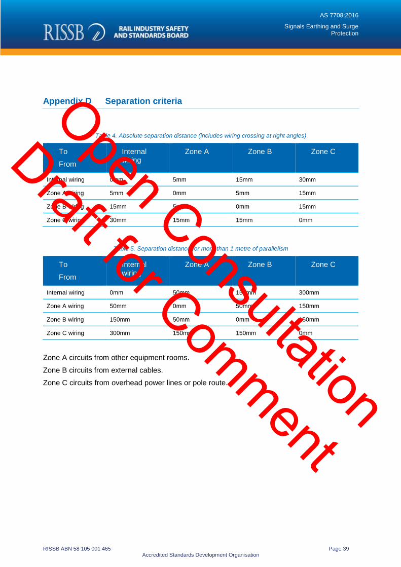
AS 7708:2016
Signals Earthing and Surge Protection
RISSB ABN 58 105 001 465 Page 39 Accredited Standards Development Organisation
Appendix D Separation criteria
Table 4. Absolute separation distance (includes wiring crossing at right angles)
To From
Internal wiring
Zone A Zone B Zone C
Internal wiring 0mm 5mm 15mm 30mm
Zone A wiring 5mm 0mm 5mm 15mm
Zone B wiring 15mm 5mm 0mm 15mm
Zone C wiring 30mm 15mm 15mm 0mm
Table 5. Separation distance for more than 1 metre of parallelism
To From
Internal wiring
Zone A Zone B Zone C
Internal wiring 0mm 50mm 150mm 300mm
Zone A wiring 50mm 0mm 50mm 150mm
Zone B wiring 150mm 50mm 0mm 150mm
Zone C wiring 300mm 150mm 150mm 0mm
Zone A circuits from other equipment rooms. Zone B circuits from external cables. Zone C circuits from overhead power lines or pole route.
Open Consultation
Draft for Comment

AS 7708:2016
Signals Earthing and Surge Protection
RISSB ABN 58 105 001 465 Page 40 Accredited Standards Development Organisation
Appendix E Lightning protection for railway signalling
Figure 6. Nominated surge categories for lightning protection equipment
Represents lightning protection equipment suitable for protection against the nominated Category of surge as detailed in AS 1768.
Open Consultation
Draft for Comment

AS 7708:2016
Signals Earthing and Surge Protection
RISSB ABN 58 105 001 465 Page 41 Accredited Standards Development Organisation
Hazard List
Hazard Number Hazard Item No.
9.2.1 Cables Failure (Design)
4.3
New Insulation failure due to overvoltage spike or surge.
9.6.1 Field Equipment and/or enclosures failures (design)
New Equipment
failure due to voltage transients
9.9.1.15
Power Supply Failure: Inadequate Surge Protection
9.15.1.1
Cable Routes Failure: Cable Routes close to hazardous voltages
9.18.1.19 Control System Failure (Construction): Lightning Surge Damage to equipment
New Hazard:
Add “and Traction voltage” to this hazard.
9.19.1.1
Field Equipment and/or enclosure failures (Construction): Lightning surge damage to equipment.
Open Consultation
Draft for Comment

AS 7708:2016
Signals Earthing and Surge Protection
RISSB ABN 58 105 001 465 Page 42 Accredited Standards Development Organisation
Hazard Number Hazard Item No.
New Hazard : Add “and Traction voltage” to this hazard.
9.22.1.13:
Power Supply Failure: (Construction): Surge Protection ineffective.
9.31.1.11 Power supply Failure: (Test and Commission): Surge Protection ineffective.
Open Consultation
Draft for Comment

ISBN Enter ISBN.
ABN 58 105 001 465
For information regarding an Australian Standard® developed by RISSB, contact:
Rail Industry Safety and Standards Board Suite 4, Level 4, Plaza Offices (East) Terminal Complex, Canberra Airport ACT 2609 Australia
PO Box 4271 Kingston ACT 2604
T +61 6270 4523 F +61 6270 4516 E [email protected]
For information regarding the sale and distribution of RISSB Standards, contact:
SAI Global Limited Phone: 13 12 42 Fax: 1300 65 49 49 Email: [email protected] http://infostore.saiglobal.com/store
ISBN: Enter ISBN.
Open Consultation
Draft for Comment

AS 7708:2016
Signals Earthing and Surge Protection
RISSB ABN 58 105 001 465 Page 1 Accredited Standards Development Organisation
The Rail Industry Safety and Standards Board (RISSB) is a not for profit company limited by guarantee. Wholly owned by its funding members, RISSB is required to apply the whole of its income and assets to achieving the objects listed in its Constitution. RISSB is responsible for the development and management of standards, rules, codes of practice and guidelines for the Australian rail industry. For further information visit www.rissb.com.au
RISSB Australian Standards Development Process The Standards development process is rigorous and transparent. Authors work with RISSB's Project Managers and Development Groups to ensure that products are acceptable to industry. Standing Committees oversee this work and ensure that proper governance and process is followed. The products are exposed to the public and industry for comment, and validated by an independent validator. Once agreed by the Development Groups, Standing Committees and Validator, the drafts are passed to the RISSB Board for approval. The same process is used in developing other RISSB products, although Guidelines are not exposed to the public for comment or validated, given their non-binding nature.
Australian Board of Standards Development Organisations RISSB is accredited by the Australian Board of Standards Development Organisations (ABSDO), and all standards produced by RISSB since 31 July 2007 are published as Australian Standards. The Accreditation Board for Standards Development Organisations (ABSDO) audits RISSB annually to ensure that RISSB’s processes are in accordance with ABSDO accreditation requirements.
Sales and Distribution Australian Standards developed by RISSB are sold and marketed through SAI Global. For further information, please visit www.saiglobal.com Financial members of RISSB are granted access with membership.
Open Consultation
Draft for Comment


