48
STAAD PRO 2007 Izhar Steel 36 Km MULTAN ROAD, Lahore, Pakistan. Tel: (92-42) 111-323-111, 5383548, Fax (92-42) 5383770 http://www.izhar.com. E-mail: [email protected] TRAINING-I

STAAD PRO 2007
Izhar Steel36 Km MULTAN ROAD,
Lahore, Pakistan.Tel: (92-42) 111-323-111, 5383548, Fax (92-42) 5383770
http://www.izhar.com. E-mail: [email protected]
TRAINING-I

∗ STAAD is a comprehensive structural engineering software that addresses all aspects of structural engineering –analysis, design, verification, and visualization.
∗ STAAD performs the analysis and design of the structure for different types of structures, such as trusses, plane, space (3D), floors (2 D plane and but loads are vertical or out of that plane).
∗ STAAD has two main methods of modeling (input editor (script language) and/or through graphical environment).
INTRODUCTION

MAIN STEP OF MODELLING
∗ Entering job information.
∗ Building model geometry.
∗ Defining member properties, sections.
∗ Assigning loads (load cases, combinations..)
∗ Defining pre-analysis print out, analysis type, and post-analysis printout.
∗ Defining design parameters.

TUTORIAL:ANALYSIS & DESIGN OF STEEL TRUSS

ANALYSIS & DESIGN OF STEEL TRUSS
∗ The figure above shows a steel truss from several trusses supposed to cover a certain area. As shown, the truss has a cantilever part its span equals 4.0m. The proposed truss depth is 3.0m.The loads as shown, are concentrated at the truss joints. The values of its load case are shown. Use all the data you take in the Steel Course for analysis and design.

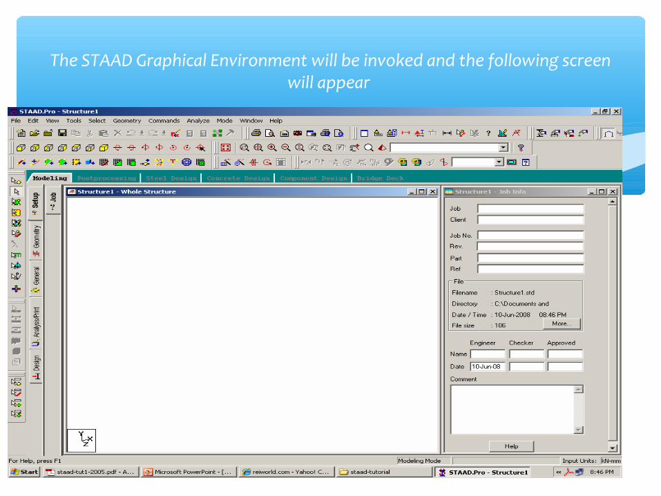
The STAAD Graphical Environment will be invoked and the following screen will appear
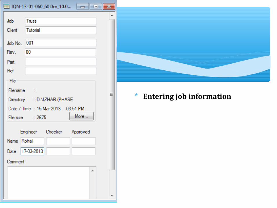
∗ Entering job information

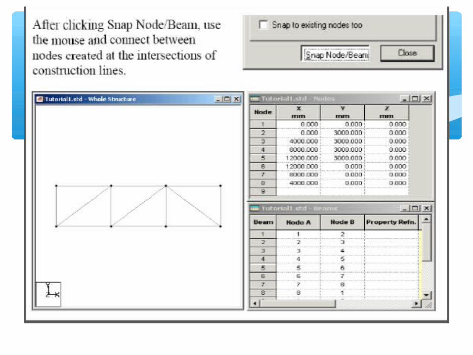
∗ 2. Building Model (Structure) Geometry
∗ One of the methods that you can create construction lines and then raw on these lines the truss members.
∗ Noting that the number of construction lines is excluding first line.

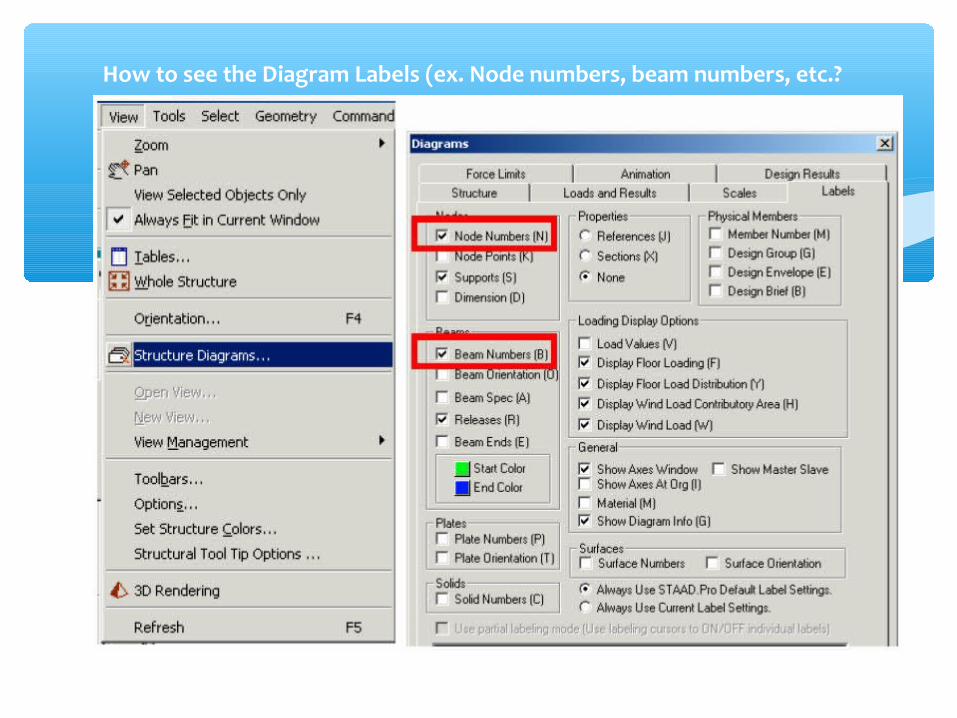
How to see the Diagram Labels (ex. Node numbers, beam numbers, etc.?

Node and beam labels are a way of identifying the entities we have drawn on the screen, and very useful when dealing with the output results.

Defining member properties, sections ∗Property: In which we can define or choose sections properties of the members of the truss.∗Spec.: In which we can define or choose members specifications.∗Support: In which we can define the supports properties (restraints).∗Load: In which we can define the applied loads, load cases, load combinations.∗Material: In which we can define the material properties.(ex. E, density, etc.)

PROPERTY ASSIGNING

PROPERTY ASSIGNING
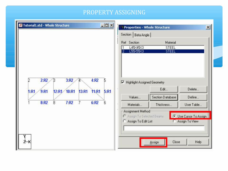
PROPERTY ASSIGNING

SUPPORTS

SUPPORTS

SUPPORTS
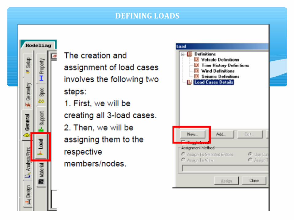
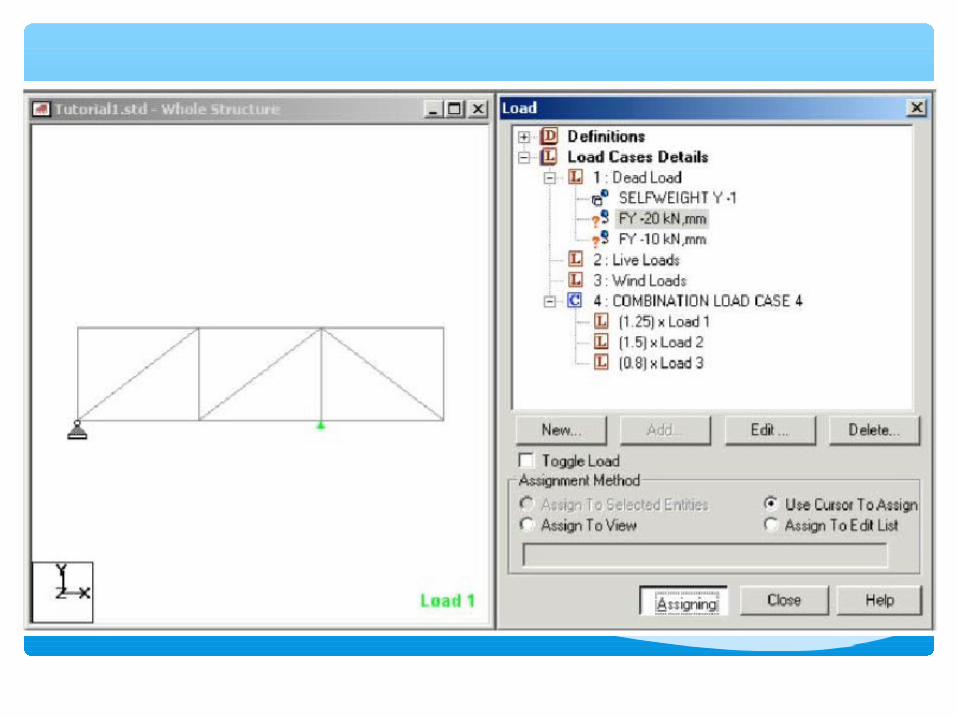
DEFINING LOADS

DEFINING LOADS


Also, we can define load combinations according to required.For example, we can create a load combination1.25 D.L. + 1.5 L.L + 0.8 W.L.


39


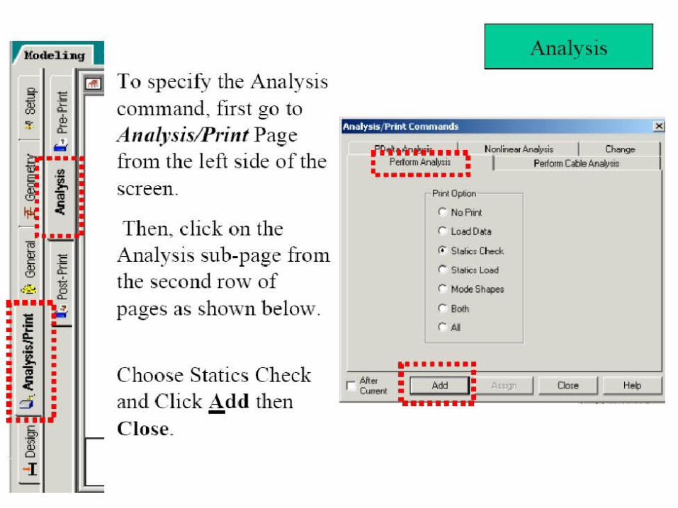
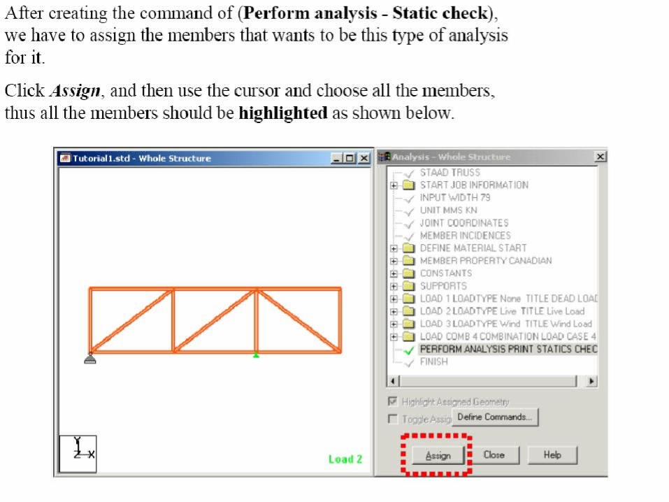
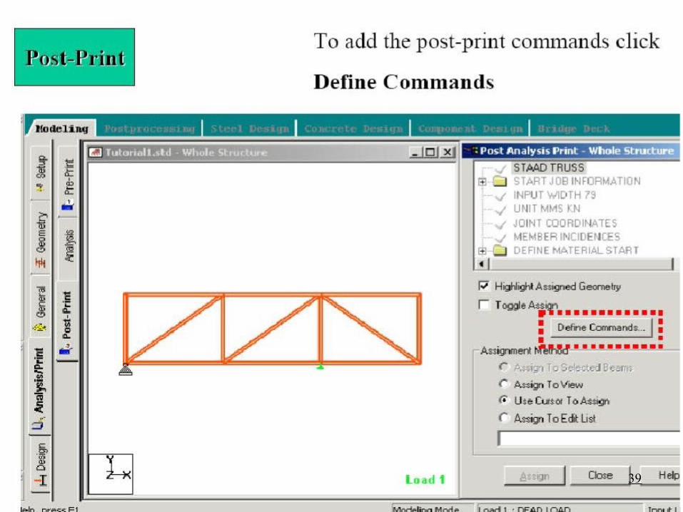
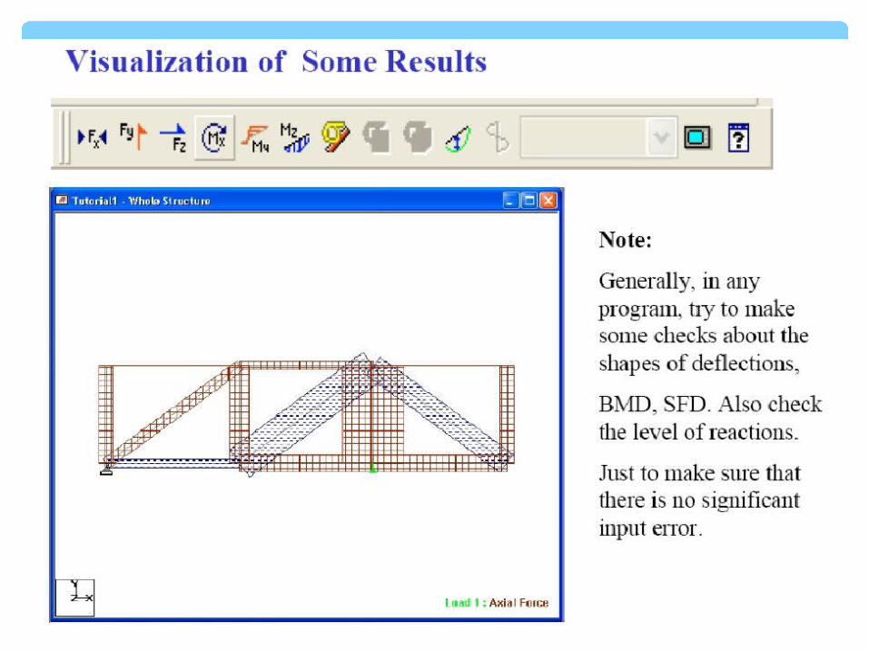
ANALYSIS & VIEWING RESULT


THANK YOU!!!


