Tranquility ® High Efficiency (TR) Series Models TRH/V 006 - 060 60Hz - HFC-410A INSTALLATION, OPERATION & MAINTENANCE 97B0075N08 Revised: 22 January, 2015 Table of Contents Model Nomenclature - General Overview 3 General Information 4 Unit Physical Data 6 Horizontal Installation 7 Field Conversion of Air Discharge 9 Horizontal Installation 10 Vertical Installation 11 Piping Installation 13 Water-Loop Heat Pump Applications 14 Ground-Loop Heat Pump Applications 15 Ground-Water Heat Pump Applications 17 Water Quality Standards 19 Electrical - Line Voltage 20 Electrical Data - Standard Unit - PSC Blower 21 Electrical Data - High Static PSC Blower 22 Electrical Data - Internal Secondary Pump - PSC Blower 23 Electrical Data - High Static PSC Blower with Internal Secondary Pump 24 Electrical Data with Climadry ® - PSC Blower 25 Electrical Data - Climadry ® & High Static PSC Blower 26 Electrical Data - ECM Blower 27 Electrical Data - ECM Blower with Internal Secondary Pump 28 Electrical Data - ECM Blower with Climadry ® 29 Electrical - Power Wiring 30 Electrical - Power & Low Voltage Wiring 31 Electrical - Low Voltage Wiring 32 Electrical - Thermostat Wiring 33 TR Blower Performance Data - Standard Unit - PSC 34 TR Blower Performance Data - High Static - PSC 35 Blower Performance Data with PSC and ClimaDry ® 36 Blower Performance Data - with High Static PSC and ClimaDry ® 37 Blower Performance Data (ECM Motor) 38 ECM Control 39 Typical Wiring Diagram - Units with CXM Controller and ECM Blower (Single Phase) 41 Typical Wiring Diagram - Units with CXM Board and PSC Fan Motor (Single Phase) 42 Typical Wiring Diagram - Units with DXM Board and PSC Fan Motor (Three Phase) 43 Typical Wiring Diagram - Single Phase with ClimaDry ® 44 CXM Controls 45 DXM Controls 46 Safety Features - CXM and DXM Controls 48 ClimaDry ® Modulating Reheat Option 50 Unit Starting and Operating Conditions 53 Piping System Cleaning and Flushing 54 Flushing/Purging Units with ClimaDry ® 55 Unit and System Checkout 56 Unit Start-Up Procedure 57 Unit Operating Conditions 59 Preventive Maintenance 63 Functional Troubleshooting 65 Performance Troubleshooting 66 Start-Up Log Sheet 67 Functional Troubleshooting 68 Warranty (U.S. & Canada) 69 Warranty (International) 70 Revision History 72
Transcript
Tranquility®
High Efficiency
(TR) Series
Models TRH/V 006 - 06060Hz - HFC-410A
INSTALLATION, OPERATION
& MAINTENANCE
97B0075N08Revised: 22 January, 2015
Table of Contents
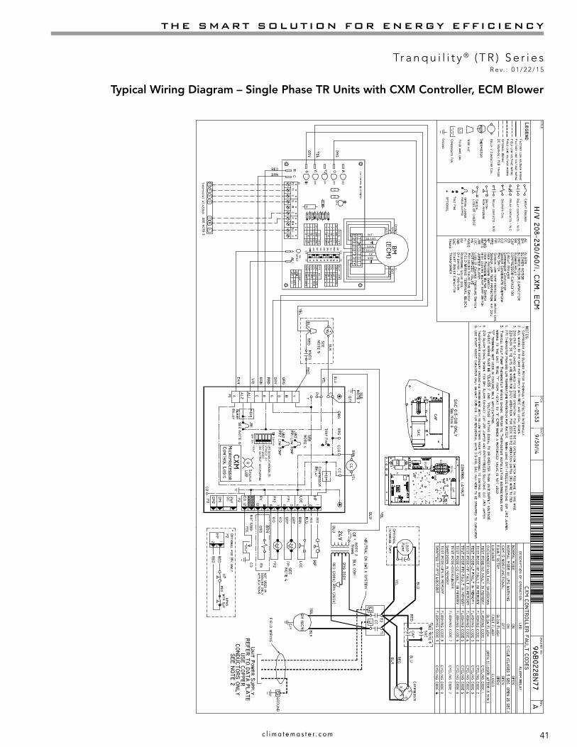
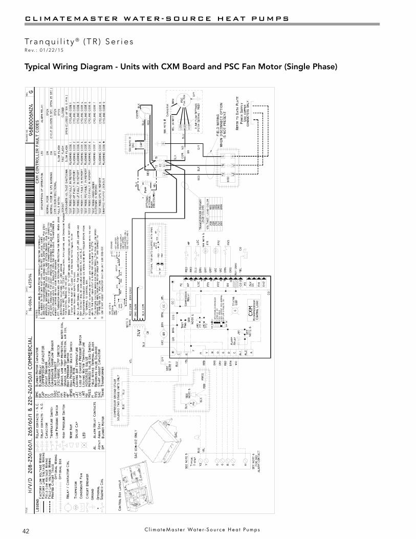
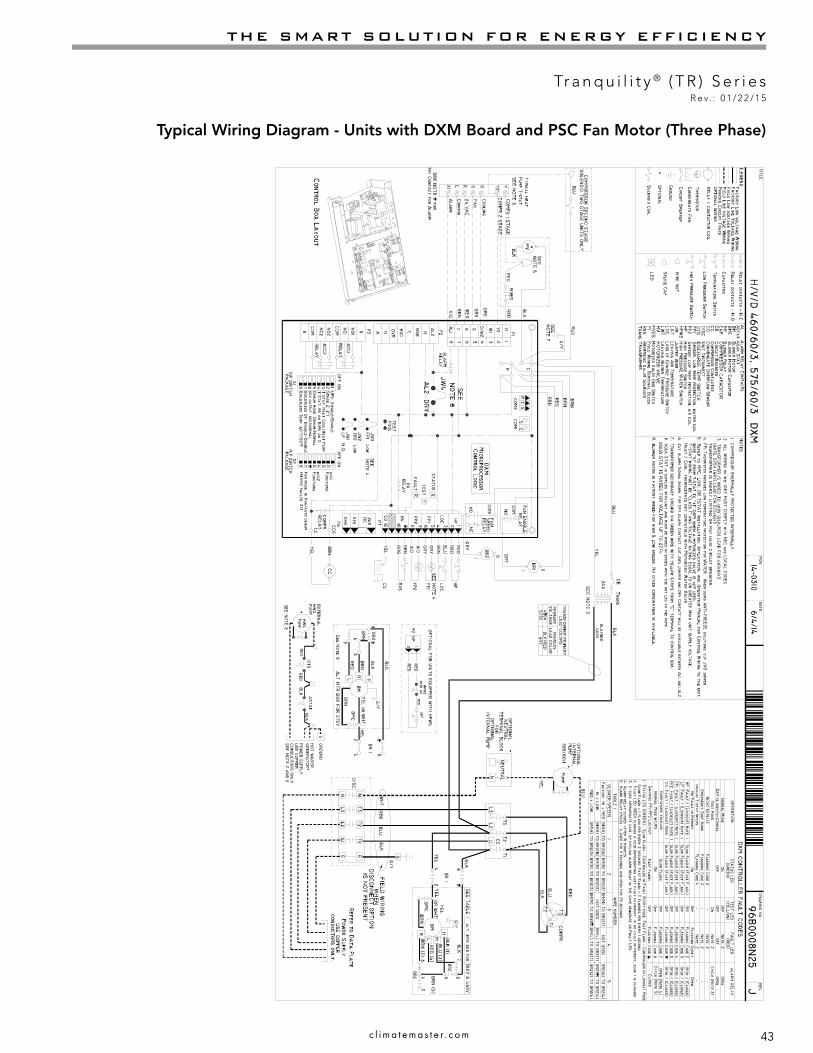
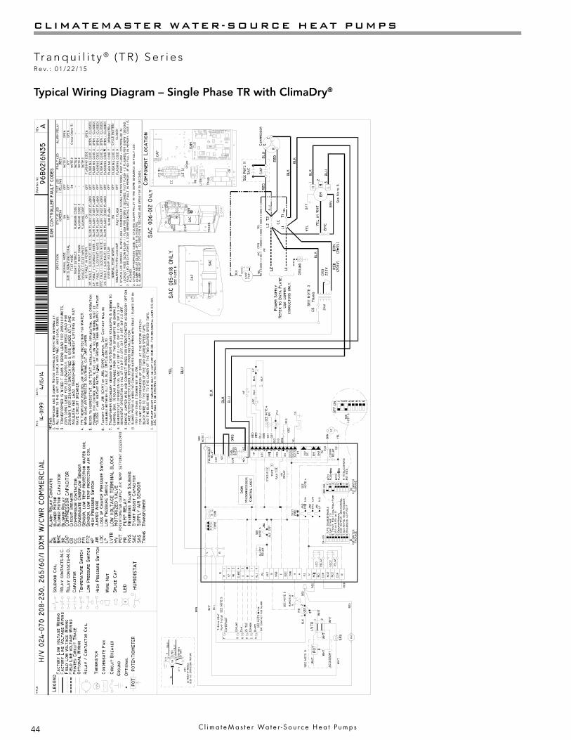
Model Nomenclature - General Overview 3General Information 4Unit Physical Data 6Horizontal Installation 7Field Conversion of Air Discharge 9Horizontal Installation 10Vertical Installation 11Piping Installation 13Water-Loop Heat Pump Applications 14Ground-Loop Heat Pump Applications 15Ground-Water Heat Pump Applications 17Water Quality Standards 19Electrical - Line Voltage 20Electrical Data - Standard Unit - PSC Blower 21Electrical Data - High Static PSC Blower 22Electrical Data - Internal Secondary Pump - PSC Blower 23Electrical Data - High Static PSC Blower with Internal Secondary Pump 24Electrical Data with Climadry® - PSC Blower 25Electrical Data - Climadry® & High Static PSC Blower 26Electrical Data - ECM Blower 27Electrical Data - ECM Blower with Internal Secondary Pump 28Electrical Data - ECM Blower with Climadry® 29Electrical - Power Wiring 30Electrical - Power & Low Voltage Wiring 31Electrical - Low Voltage Wiring 32Electrical - Thermostat Wiring 33TR Blower Performance Data - Standard Unit - PSC 34TR Blower Performance Data - High Static - PSC 35Blower Performance Data with PSC and ClimaDry® 36Blower Performance Data - with High Static PSC and ClimaDry® 37Blower Performance Data (ECM Motor) 38ECM Control 39Typical Wiring Diagram - Units with CXM Controller and ECM Blower (Single Phase) 41Typical Wiring Diagram - Units with CXM Board andPSC Fan Motor (Single Phase) 42Typical Wiring Diagram - Units with DXM Board and PSC Fan Motor (Three Phase) 43Typical Wiring Diagram - Single Phase with ClimaDry® 44CXM Controls 45DXM Controls 46Safety Features - CXM and DXM Controls 48ClimaDry® Modulating Reheat Option 50Unit Starting and Operating Conditions 53Piping System Cleaning and Flushing 54Flushing/Purging Units with ClimaDry® 55Unit and System Checkout 56Unit Start-Up Procedure 57Unit Operating Conditions 59Preventive Maintenance 63Functional Troubleshooting 65Performance Troubleshooting 66Start-Up Log Sheet 67Functional Troubleshooting 68Warranty (U.S. & Canada) 69Warranty (International) 70Revision History 72
2
CLIMATEMASTER WATER-SOURCE HEAT PUMPS
Tr a n q u i l i t y ® ( T R ) S e r i e sR e v. : 0 1 / 2 2 / 1 5
C l i m a t e M a s t e r Wa t e r - S o u r c e H e a t P u m p s
This Page Intentionally Left Blank
3
THE SMART SOLUTION FOR ENERGY EFFICIENCY
Tr a n q u i l i t y ® ( T R ) S e r i e sR e v. : 0 1 / 2 2 / 1 5
c l i m a t e m a s t e r . c o m
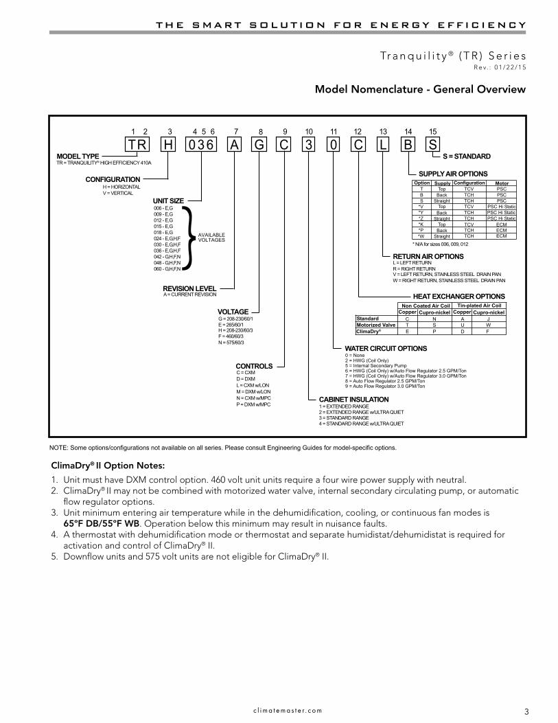
T R H A0 3 6 CG 3 0 C L B S1 2 3 4 5 6 7 8 9 10 11 12 13 14 15
S Straight TCH PSC*V TCV PSC Hi Static*Y TCH*Z TCH
TopBack
Straight*K TCV ECM*P TCH*W TCH
TopBack
Straight
PSC Hi StaticPSC Hi Static
ECMECM
Model Nomenclature - General Overview
NOTE: Some options/configurations not available on all series. Please consult Engineering Guides for model-specific options.
ClimaDry® II Option Notes:
1. Unit must have DXM control option. 460 volt unit units require a four wire power supply with neutral.2. ClimaDry® II may not be combined with motorized water valve, internal secondary circulating pump, or automatic
flow regulator options.3. Unit minimum entering air temperature while in the dehumidification, cooling, or continuous fan modes is
65ºF DB/55ºF WB. Operation below this minimum may result in nuisance faults. 4. A thermostat with dehumidification mode or thermostat and separate humidistat/dehumidistat is required for
activation and control of ClimaDry® II.5. Downflow units and 575 volt units are not eligible for ClimaDry® II.
4
CLIMATEMASTER WATER-SOURCE HEAT PUMPS
Tr a n q u i l i t y ® ( T R ) S e r i e sR e v. : 0 1 / 2 2 / 1 5
C l i m a t e M a s t e r Wa t e r - S o u r c e H e a t P u m p s
General Information
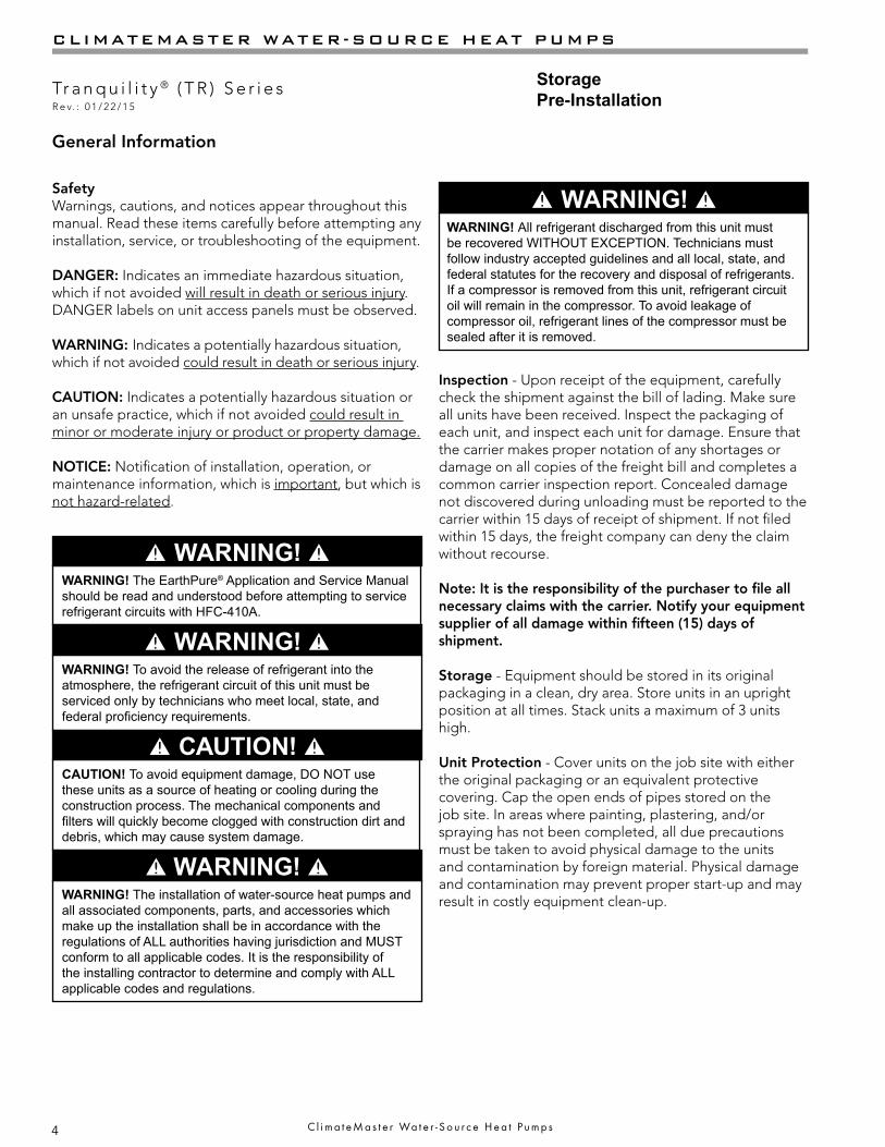
WARNING! To avoid the release of refrigerant into the atmosphere, the refrigerant circuit of this unit must be serviced only by technicians who meet local, state, and federal proficiency requirements.
WARNING! All refrigerant discharged from this unit must be recovered WITHOUT EXCEPTION. Technicians must follow industry accepted guidelines and all local, state, and federal statutes for the recovery and disposal of refrigerants. If a compressor is removed from this unit, refrigerant circuit oil will remain in the compressor. To avoid leakage of compressor oil, refrigerant lines of the compressor must be sealed after it is removed.
CAUTION! To avoid equipment damage, DO NOT use these units as a source of heating or cooling during the construction process. The mechanical components and filters will quickly become clogged with construction dirt and debris, which may cause system damage.
� WARNING! �
� WARNING! �
� WARNING! �
� CAUTION! �
SafetyWarnings, cautions, and notices appear throughout this manual. Read these items carefully before attempting any installation, service, or troubleshooting of the equipment.
DANGER: Indicates an immediate hazardous situation, which if not avoided will result in death or serious injury. DANGER labels on unit access panels must be observed.
WARNING: Indicates a potentially hazardous situation, which if not avoided could result in death or serious injury.
CAUTION: Indicates a potentially hazardous situation or an unsafe practice, which if not avoided could result in minor or moderate injury or product or property damage.
NOTICE: Notification of installation, operation, or maintenance information, which is important, but which is not hazard-related.
WARNING! The EarthPure® Application and Service Manual should be read and understood before attempting to service refrigerant circuits with HFC-410A.
Inspection - Upon receipt of the equipment, carefully check the shipment against the bill of lading. Make sure all units have been received. Inspect the packaging of each unit, and inspect each unit for damage. Ensure that the carrier makes proper notation of any shortages or damage on all copies of the freight bill and completes a common carrier inspection report. Concealed damage not discovered during unloading must be reported to the carrier within 15 days of receipt of shipment. If not filed within 15 days, the freight company can deny the claim without recourse.
Note: It is the responsibility of the purchaser to file all necessary claims with the carrier. Notify your equipment supplier of all damage within fifteen (15) days of shipment.
Storage - Equipment should be stored in its original packaging in a clean, dry area. Store units in an upright position at all times. Stack units a maximum of 3 units high.
Unit Protection - Cover units on the job site with either the original packaging or an equivalent protective covering. Cap the open ends of pipes stored on the job site. In areas where painting, plastering, and/or spraying has not been completed, all due precautions must be taken to avoid physical damage to the units and contamination by foreign material. Physical damage and contamination may prevent proper start-up and may result in costly equipment clean-up.
StoragePre-Installation
� WARNING! �WARNING! The installation of water-source heat pumps and all associated components, parts, and accessories which make up the installation shall be in accordance with the regulations of ALL authorities having jurisdiction and MUST conform to all applicable codes. It is the responsibility of the installing contractor to determine and comply with ALL applicable codes and regulations.
5
THE SMART SOLUTION FOR ENERGY EFFICIENCY
Tr a n q u i l i t y ® ( T R ) S e r i e sR e v. : 0 1 / 2 2 / 1 5
c l i m a t e m a s t e r . c o m
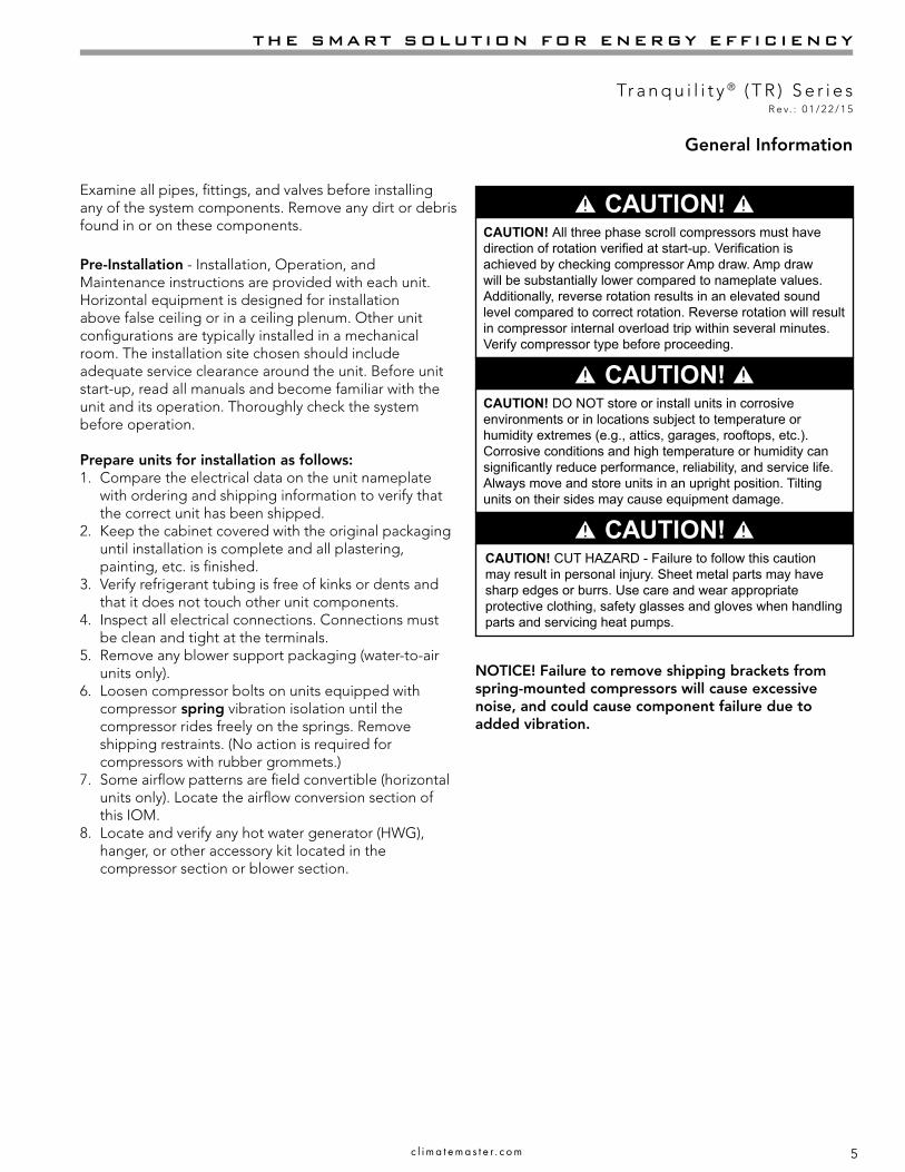
CAUTION! All three phase scroll compressors must have direction of rotation verified at start-up. Verification is achieved by checking compressor Amp draw. Amp draw will be substantially lower compared to nameplate values. Additionally, reverse rotation results in an elevated sound level compared to correct rotation. Reverse rotation will result in compressor internal overload trip within several minutes. Verify compressor type before proceeding.
CAUTION! DO NOT store or install units in corrosive environments or in locations subject to temperature or humidity extremes (e.g., attics, garages, rooftops, etc.). Corrosive conditions and high temperature or humidity can significantly reduce performance, reliability, and service life. Always move and store units in an upright position. Tilting units on their sides may cause equipment damage.
NOTICE! Failure to remove shipping brackets from spring-mounted compressors will cause excessive noise, and could cause component failure due to added vibration.
� CAUTION! �
� CAUTION! �
� CAUTION! �CAUTION! CUT HAZARD - Failure to follow this caution may result in personal injury. Sheet metal parts may have sharp edges or burrs. Use care and wear appropriate protective clothing, safety glasses and gloves when handling parts and servicing heat pumps.
General Information
Examine all pipes, fittings, and valves before installing any of the system components. Remove any dirt or debris found in or on these components.
Pre-Installation - Installation, Operation, and Maintenance instructions are provided with each unit. Horizontal equipment is designed for installation above false ceiling or in a ceiling plenum. Other unit configurations are typically installed in a mechanical room. The installation site chosen should include adequate service clearance around the unit. Before unit start-up, read all manuals and become familiar with the unit and its operation. Thoroughly check the system before operation.
Prepare units for installation as follows:1. Compare the electrical data on the unit nameplate
with ordering and shipping information to verify that the correct unit has been shipped.
2. Keep the cabinet covered with the original packaging until installation is complete and all plastering, painting, etc. is finished.
3. Verify refrigerant tubing is free of kinks or dents and that it does not touch other unit components.
4. Inspect all electrical connections. Connections must be clean and tight at the terminals.
5. Remove any blower support packaging (water-to-air units only).
6. Loosen compressor bolts on units equipped with compressor spring vibration isolation until the compressor rides freely on the springs. Remove shipping restraints. (No action is required for compressors with rubber grommets.)
7. Some airflow patterns are field convertible (horizontal units only). Locate the airflow conversion section of this IOM.
8. Locate and verify any hot water generator (HWG), hanger, or other accessory kit located in the compressor section or blower section.
6
CLIMATEMASTER WATER-SOURCE HEAT PUMPS
Tr a n q u i l i t y ® ( T R ) S e r i e sR e v. : 0 1 / 2 2 / 1 5
C l i m a t e M a s t e r Wa t e r - S o u r c e H e a t P u m p s
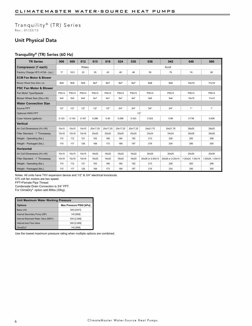
Notes: All units have TXV expansion device and 1/2” & 3/4” electrical knockouts.575 volt fan motors are two speed.FPT=Female Pipe ThreadCondensate Drain Connection is 3/4” FPT.For ClimaDry® option add 66lbs (30kg).
Unit Maximum Water Working PressureOptions Max Pressure PSIG [kPa]
Base Unit 500 [3447]
Internal Secondary Pump (ISP) 145 [999]
Internal Motorized Water Valve (MWV) 300 [2,068]
Internal Auto Flow Valve 300 [2,068]
ClimaDry® 145 [999]
Use the lowest maximum pressure rating when multiple options are combined.
Unit Physical Data
Tranquility® (TR) Series (60 Hz)
7
THE SMART SOLUTION FOR ENERGY EFFICIENCY
Tr a n q u i l i t y ® ( T R ) S e r i e sR e v. : 0 1 / 2 2 / 1 5
c l i m a t e m a s t e r . c o m
Horizontal Installation
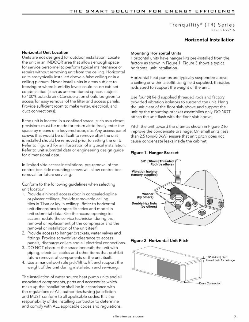
Mounting Horizontal UnitsHorizontal units have hanger kits pre-installed from the factory as shown in Figure 1. Figure 3 shows a typical horizontal unit installation.
Horizontal heat pumps are typically suspended above a ceiling or within a soffit using field supplied, threaded rods sized to support the weight of the unit.
Use four (4) field supplied threaded rods and factory provided vibration isolators to suspend the unit. Hang the unit clear of the floor slab above and support the unit by the mounting bracket assemblies only. DO NOT attach the unit flush with the floor slab above.
Pitch the unit toward the drain as shown in Figure 2 to improve the condensate drainage. On small units (less than 2.5 tons/8.8kW) ensure that unit pitch does not cause condensate leaks inside the cabinet.
Figure 1: Hanger Bracket
Figure 2: Horizontal Unit Pitch
3/8" [10mm] ThreadedRod (by others)
Vibration Isolator(factory supplied)
Washer(by others)
Double Hex Nuts(by others)
Varilla Roscada de 3/8"(fabricada por terceros)
Arandela(fabricada por terceros)Tuercas HexagonalesDobles (por terceros)
Instale los Tornillos comose Indica en el Diagrama
La longitud de este tornillodebe ser de solamente 1/2” para evitar daños
Aislador de Vibraciones(para codificación por color ynotas de instalación, consultelas instrucciones deinstalación del soporte colgador)
1/4” (6.4mm) pitchtoward drain for drainage
Drain Connection
Horizontal Unit LocationUnits are not designed for outdoor installation. Locate the unit in an INDOOR area that allows enough space for service personnel to perform typical maintenance or repairs without removing unit from the ceiling. Horizontal units are typically installed above a false ceiling or in a ceiling plenum. Never install units in areas subject to freezing or where humidity levels could cause cabinet condensation (such as unconditioned spaces subject to 100% outside air). Consideration should be given to access for easy removal of the filter and access panels. Provide sufficient room to make water, electrical, and duct connection(s).
If the unit is located in a confined space, such as a closet, provisions must be made for return air to freely enter the space by means of a louvered door, etc. Any access panel screws that would be difficult to remove after the unit is installed should be removed prior to setting the unit. Refer to Figure 3 for an illustration of a typical installation. Refer to unit submittal data or engineering design guide for dimensional data.
In limited side access installations, pre-removal of the control box side mounting screws will allow control box removal for future servicing.
Conform to the following guidelines when selecting unit location:1. Provide a hinged access door in concealed-spline
or plaster ceilings. Provide removable ceiling tiles in T-bar or lay-in ceilings. Refer to horizontal unit dimensions for specific series and model in unit submittal data. Size the access opening to accommodate the service technician during the removal or replacement of the compressor and the removal or installation of the unit itself.
2. Provide access to hanger brackets, water valves and fittings. Provide screwdriver clearance to access panels, discharge collars and all electrical connections.
3. DO NOT obstruct the space beneath the unit with piping, electrical cables and other items that prohibit future removal of components or the unit itself.
4. Use a manual portable jack/lift to lift and support the weight of the unit during installation and servicing.
The installation of water source heat pump units and all associated components, parts and accessories which make up the installation shall be in accordance with the regulations of ALL authorities having jurisdiction and MUST conform to all applicable codes. It is the responsibility of the installing contractor to determine and comply with ALL applicable codes and regulations.
8
CLIMATEMASTER WATER-SOURCE HEAT PUMPS
Tr a n q u i l i t y ® ( T R ) S e r i e sR e v. : 0 1 / 2 2 / 1 5
C l i m a t e M a s t e r Wa t e r - S o u r c e H e a t P u m p s
Horizontal Installation
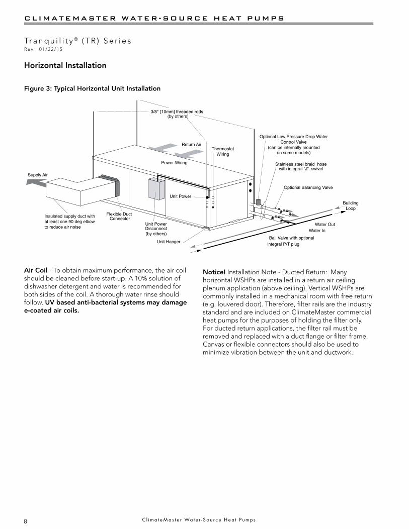
Figure 3: Typical Horizontal Unit Installation
Air Coil - To obtain maximum performance, the air coil should be cleaned before start-up. A 10% solution of dishwasher detergent and water is recommended for both sides of the coil. A thorough water rinse should follow. UV based anti-bacterial systems may damage e-coated air coils.
HORIZONTAL INSTALLATION
(by others)
(by others)
Cableadodel termostato
Válvula compensadora opcional
Salida de aguaEntrada de agua
Válvula invertida opcional paracontrol de baja presión de agua
(puede montarse en forma interna)
Válvula a bola con tapónP/T integrado opcional
Manguera trenzada deacero inoxidable con accesorio
giratorio en “J”
Circuitode edificación
Disyuntor deenergía de la unidad
(fabricado por terceros)
Alimentaciónde energía de
la unidad
Conducto de alimentaciónaislado con un codo (mínimo)de 90 grados para reducir el
ruido del aire
Retorno deaire
Aire de alimentación
Cableado dealimentaciónde energía
Varillas Roscadas de 3/8"(fabricadas por terceros)
Colgadorde la unidad
ThermostatWiring
Water InWater Out
Optional Balancing Valve
Ball Valve with optionalintegral P/T plug
Stainless steel braid hosewith integral "J" swivel
BuildingLoop
Unit PowerDisconnect
Power Wiring
Insulated supply duct withat least one 90 deg elbowto reduce air noise
Return Air
Supply Air
Unit Hanger
3/8" [10mm] threaded rods
Unit Power
Flexible DuctConnector
Figure 3: Typical Horizontal Unit Installation
Optional Low Pressure Drop WaterControl Valve
(can be internally mountedon some models)
Notice! Installation Note - Ducted Return: Many horizontal WSHPs are installed in a return air ceiling plenum application (above ceiling). Vertical WSHPs are commonly installed in a mechanical room with free return (e.g. louvered door). Therefore, filter rails are the industry standard and are included on ClimateMaster commercial heat pumps for the purposes of holding the filter only. For ducted return applications, the filter rail must be removed and replaced with a duct flange or filter frame. Canvas or flexible connectors should also be used to minimize vibration between the unit and ductwork.
9
THE SMART SOLUTION FOR ENERGY EFFICIENCY
Tr a n q u i l i t y ® ( T R ) S e r i e sR e v. : 0 1 / 2 2 / 1 5
c l i m a t e m a s t e r . c o m
Field Conversion of Air Discharge
Water Connection End
Return Air
Remove Screws
Water Connection End
Return Air
Rotate
Move to Side
Side Discharge
Return Air
Water Connection End
Discharge Air
Drain
Back Discharge
Replace Screws
Extremo de Con
Conducto de Alimentación
Retorno de Aire
Extremo de Conexión de Agua
Drenaje
Retorno de Aire
Descarga de Aire
Descarga Lateral
Descarga Posterior
WaterConnection End
Supply Duct
Return Air
WaterConnection End
Drain
Return Air
Discharge Air
Side Discharge
Back Discharge
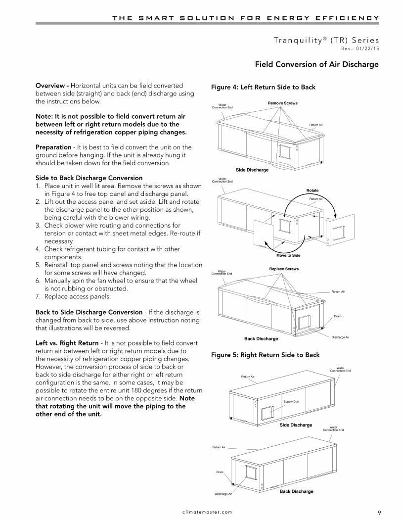
Overview - Horizontal units can be field converted between side (straight) and back (end) discharge using the instructions below.
Note: It is not possible to field convert return air between left or right return models due to the necessity of refrigeration copper piping changes.
Preparation - It is best to field convert the unit on the ground before hanging. If the unit is already hung it should be taken down for the field conversion.
Side to Back Discharge Conversion1. Place unit in well lit area. Remove the screws as shown
in Figure 4 to free top panel and discharge panel.2. Lift out the access panel and set aside. Lift and rotate
the discharge panel to the other position as shown, being careful with the blower wiring.
3. Check blower wire routing and connections for tension or contact with sheet metal edges. Re-route if necessary.
4. Check refrigerant tubing for contact with other components.
5. Reinstall top panel and screws noting that the location for some screws will have changed.
6. Manually spin the fan wheel to ensure that the wheel is not rubbing or obstructed.
7. Replace access panels.
Back to Side Discharge Conversion - If the discharge is changed from back to side, use above instruction noting that illustrations will be reversed.
Left vs. Right Return - It is not possible to field convert return air between left or right return models due to the necessity of refrigeration copper piping changes. However, the conversion process of side to back or back to side discharge for either right or left return configuration is the same. In some cases, it may be possible to rotate the entire unit 180 degrees if the return air connection needs to be on the opposite side. Note that rotating the unit will move the piping to the other end of the unit.
Figure 5: Right Return Side to Back
Figure 4: Left Return Side to Back
10
CLIMATEMASTER WATER-SOURCE HEAT PUMPS
Tr a n q u i l i t y ® ( T R ) S e r i e sR e v. : 0 1 / 2 2 / 1 5
C l i m a t e M a s t e r Wa t e r - S o u r c e H e a t P u m p s
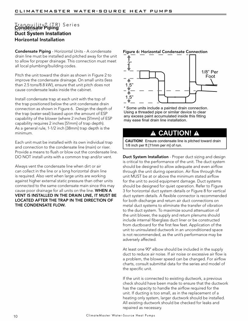
2”
1.5”
1.5”
* Some units include a painted drain connection. Using a threaded pipe or similar device to clear any excess paint accumulated inside this fitting may ease final drain line installation.
1/8” Per Foot
Condensate Piping - Horizontal Units - A condensate drain line must be installed and pitched away for the unit to allow for proper drainage. This connection must meet all local plumbing/building codes.
Pitch the unit toward the drain as shown in Figure 2 to improve the condensate drainage. On small units (less than 2.5 tons/8.8 kW), ensure that unit pitch does not cause condensate leaks inside the cabinet.
Install condensate trap at each unit with the top of the trap positioned below the unit condensate drain connection as shown in Figure 6. Design the depth of the trap (water-seal) based upon the amount of ESP capability of the blower (where 2 inches [51mm] of ESP capability requires 2 inches [51mm] of trap depth). As a general rule, 1-1/2 inch [38mm] trap depth is the minimum.
Each unit must be installed with its own individual trap and connection to the condensate line (main) or riser. Provide a means to flush or blow out the condensate line. DO NOT install units with a common trap and/or vent.
Always vent the condensate line when dirt or air can collect in the line or a long horizontal drain line is required. Also vent when large units are working against higher external static pressure than other units connected to the same condensate main since this may cause poor drainage for all units on the line. WHEN A VENT IS INSTALLED IN THE DRAIN LINE, IT MUST BE LOCATED AFTER THE TRAP IN THE DIRECTION OF THE CONDENSATE FLOW.
Horizontal Installation
Figure 6: Horizontal Condensate Connection
CAUTION! Ensure condensate line is pitched toward drain 1/8 inch per ft [11mm per m] of run.
� CAUTION! �
Duct System Installation - Proper duct sizing and design is critical to the performance of the unit. The duct system should be designed to allow adequate and even airflow through the unit during operation. Air flow through the unit MUST be at or above the minimum stated airflow for the unit to avoid equipment damage. Duct systems should be designed for quiet operation. Refer to Figure 3 for horizontal duct system details or Figure 8 for vertical duct system details. A flexible connector is recommended for both discharge and return air duct connections on metal duct systems to eliminate the transfer of vibration to the duct system. To maximize sound attenuation of the unit blower, the supply and return plenums should include internal fiberglass duct liner or be constructed from ductboard for the first few feet. Application of the unit to uninsulated ductwork in an unconditioned space is not recommended, as the unit’s performance may be adversely affected.
At least one 90° elbow should be included in the supply duct to reduce air noise. If air noise or excessive air flow is a problem, the blower speed can be changed. For airflow charts, consult submittal data for the series and model of the specific unit.
If the unit is connected to existing ductwork, a previous check should have been made to ensure that the ductwork has the capacity to handle the airflow required for the unit. If ducting is too small, as in the replacement of a heating only system, larger ductwork should be installed. All existing ductwork should be checked for leaks and repaired as necessary.
Condensate PipingDuct System Installation
11
THE SMART SOLUTION FOR ENERGY EFFICIENCY
Tr a n q u i l i t y ® ( T R ) S e r i e sR e v. : 0 1 / 2 2 / 1 5
c l i m a t e m a s t e r . c o m
Vertical Installation
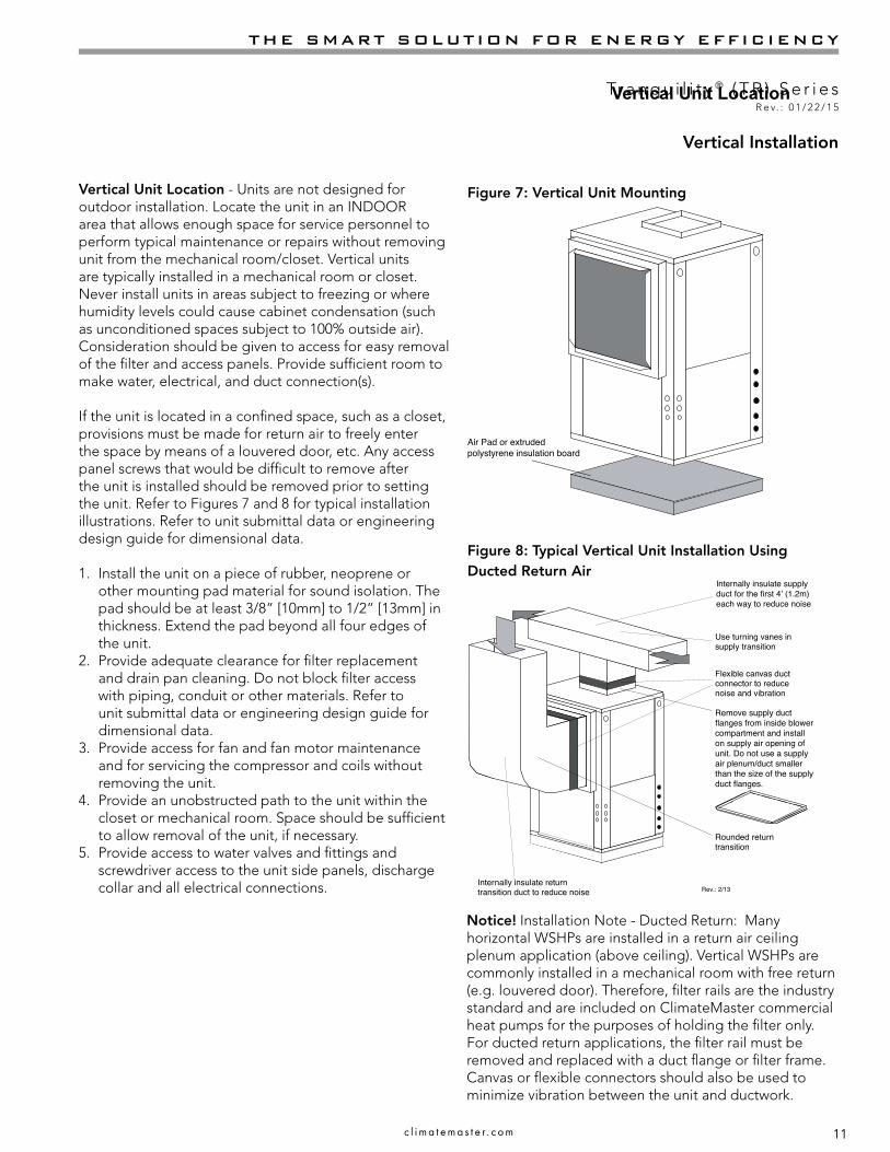
Flexible canvas ductconnector to reducenoise and vibration
Use turning vanes insupply transition
Internally insulate supplyduct for first 1.2 m each wayto reduce noise
Internally insulate returntransition duct to reduce noise
Flexible canvas ductconnector to reducenoise and vibration
Use turning vanes insupply transition
Internally insulate returntransition duct to reduce noise Rev.: 2/13
Rev.: 2/13
Internally insulate supplyduct for the first 4’ (1.2m) each way to reduce noise
Rounded returntransition
Rounded returntransition
Remove supply ductflanges from inside blowercompartment and installon supply air opening ofunit. Do not use a supplyair plenum/duct smaller than the size of the supply duct flanges.
Remove supply ductflanges from inside blowercompartment and installon supply air opening ofunit. Do not use a supplyair plenum/duct smaller than the size of the supply duct flanges.
Figure 7: Vertical Unit Mounting
Figure 8: Typical Vertical Unit Installation Using Ducted Return Air
bloque o del ladrillo o sacado
Cojín del aire o sacadoBloque o ladrillo concreto
Air Pad or extrudedpolystyrene insulation board
Vertical Unit Location - Units are not designed for outdoor installation. Locate the unit in an INDOOR area that allows enough space for service personnel to perform typical maintenance or repairs without removing unit from the mechanical room/closet. Vertical units are typically installed in a mechanical room or closet. Never install units in areas subject to freezing or where humidity levels could cause cabinet condensation (such as unconditioned spaces subject to 100% outside air). Consideration should be given to access for easy removal of the filter and access panels. Provide sufficient room to make water, electrical, and duct connection(s).
If the unit is located in a confined space, such as a closet, provisions must be made for return air to freely enter the space by means of a louvered door, etc. Any access panel screws that would be difficult to remove after the unit is installed should be removed prior to setting the unit. Refer to Figures 7 and 8 for typical installation illustrations. Refer to unit submittal data or engineering design guide for dimensional data.
1. Install the unit on a piece of rubber, neoprene or other mounting pad material for sound isolation. The pad should be at least 3/8” [10mm] to 1/2” [13mm] in thickness. Extend the pad beyond all four edges of the unit.
2. Provide adequate clearance for filter replacement and drain pan cleaning. Do not block filter access with piping, conduit or other materials. Refer to unit submittal data or engineering design guide for dimensional data.
3. Provide access for fan and fan motor maintenance and for servicing the compressor and coils without removing the unit.
4. Provide an unobstructed path to the unit within the closet or mechanical room. Space should be sufficient to allow removal of the unit, if necessary.
5. Provide access to water valves and fittings and screwdriver access to the unit side panels, discharge collar and all electrical connections.
Vertical Unit Location
Notice! Installation Note - Ducted Return: Many horizontal WSHPs are installed in a return air ceiling plenum application (above ceiling). Vertical WSHPs are commonly installed in a mechanical room with free return (e.g. louvered door). Therefore, filter rails are the industry standard and are included on ClimateMaster commercial heat pumps for the purposes of holding the filter only. For ducted return applications, the filter rail must be removed and replaced with a duct flange or filter frame. Canvas or flexible connectors should also be used to minimize vibration between the unit and ductwork.
12
CLIMATEMASTER WATER-SOURCE HEAT PUMPS
Tr a n q u i l i t y ® ( T R ) S e r i e sR e v. : 0 1 / 2 2 / 1 5
C l i m a t e M a s t e r Wa t e r - S o u r c e H e a t P u m p s
Vertical Installation
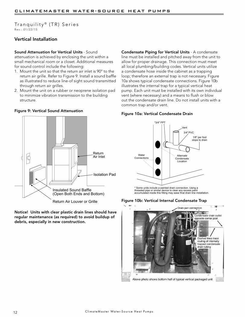
Sound Attenuation for Vertical Units - Sound attenuation is achieved by enclosing the unit within a small mechanical room or a closet. Additional measures for sound control include the following:1. Mount the unit so that the return air inlet is 90° to the
return air grille. Refer to Figure 9. Install a sound baffle as illustrated to reduce line-of sight sound transmitted through return air grilles.
2. Mount the unit on a rubber or neoprene isolation pad to minimize vibration transmission to the building structure.
Return Air Inlet
Figure 9: Vertical Sound Attenuation
Condensate Piping for Vertical Units - A condensate line must be installed and pitched away from the unit to allow for proper drainage. This connection must meet all local plumbing/building codes. Vertical units utilize a condensate hose inside the cabinet as a trapping loop; therefore an external trap is not necessary. Figure 10a shows typical condensate connections. Figure 10b illustrates the internal trap for a typical vertical heat pump. Each unit must be installed with its own individual vent (where necessary) and a means to flush or blow out the condensate drain line. Do not install units with a common trap and/or vent.
Vent
*3/4" FPT
3/4" PVC
AlternateCondensate
Location
WaterConnections
* Some units include a painted drain connection. Using athreaded pipe or similar device to clear any excess paintaccumulated inside this fitting may ease final drain line installation.
1/8" per footslope to drain
Figure 10a: Vertical Condensate Drain
Figure 10b: Vertical Internal Condensate Trap
Notice! Units with clear plastic drain lines should have regular maintenance (as required) to avoid buildup of debris, especially in new construction.
13
THE SMART SOLUTION FOR ENERGY EFFICIENCY
Tr a n q u i l i t y ® ( T R ) S e r i e sR e v. : 0 1 / 2 2 / 1 5
c l i m a t e m a s t e r . c o m
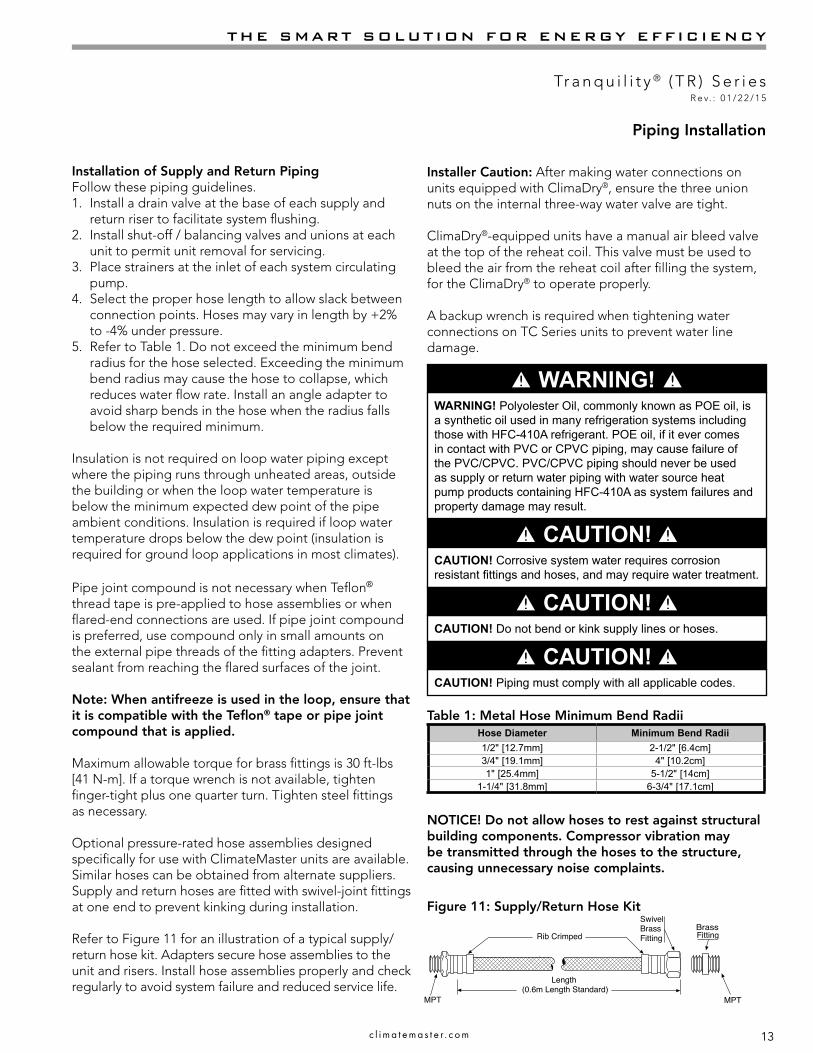
Piping Installation
CAUTION! Corrosive system water requires corrosion resistant fittings and hoses, and may require water treatment.
Table 1: Metal Hose Minimum Bend RadiiHose Diameter Minimum Bend Radii1/2" [12.7mm] 2-1/2" [6.4cm]3/4" [19.1mm] 4" [10.2cm]1" [25.4mm] 5-1/2" [14cm]
1-1/4" [31.8mm] 6-3/4" [17.1cm]
CAUTION! Do not bend or kink supply lines or hoses.
NOTICE! Do not allow hoses to rest against structural building components. Compressor vibration may be transmitted through the hoses to the structure, causing unnecessary noise complaints.
Figure 11: Supply/Return Hose Kit
� CAUTION! �
� CAUTION! �
� CAUTION! �
Rib Crimped
Length(2 ft [0.6m] Length Standard)
SwivelBrassFitting
BrassFitting
MPT
Reborde Acanalado
Longitud(Long. Estándar de 2 pies)
AccesorioGiratoriode Bronce
Accesoriode Bronce
MPT
MPT
MPT
Rib Crimped
Length(0.6m Length Standard)
SwivelBrassFitting
BrassFitting
MPTMPT
CAUTION! Piping must comply with all applicable codes.
Installation of Supply and Return PipingFollow these piping guidelines.1. Install a drain valve at the base of each supply and
return riser to facilitate system flushing.2. Install shut-off / balancing valves and unions at each
unit to permit unit removal for servicing.3. Place strainers at the inlet of each system circulating
pump.4. Select the proper hose length to allow slack between
connection points. Hoses may vary in length by +2% to -4% under pressure.
5. Refer to Table 1. Do not exceed the minimum bend radius for the hose selected. Exceeding the minimum bend radius may cause the hose to collapse, which reduces water flow rate. Install an angle adapter to avoid sharp bends in the hose when the radius falls below the required minimum.
Insulation is not required on loop water piping except where the piping runs through unheated areas, outside the building or when the loop water temperature is below the minimum expected dew point of the pipe ambient conditions. Insulation is required if loop water temperature drops below the dew point (insulation is required for ground loop applications in most climates).
Pipe joint compound is not necessary when Teflon® thread tape is pre-applied to hose assemblies or when flared-end connections are used. If pipe joint compound is preferred, use compound only in small amounts on the external pipe threads of the fitting adapters. Prevent sealant from reaching the flared surfaces of the joint.
Note: When antifreeze is used in the loop, ensure that it is compatible with the Teflon® tape or pipe joint compound that is applied.
Maximum allowable torque for brass fittings is 30 ft-lbs [41 N-m]. If a torque wrench is not available, tighten finger-tight plus one quarter turn. Tighten steel fittings as necessary.
Optional pressure-rated hose assemblies designed specifically for use with ClimateMaster units are available. Similar hoses can be obtained from alternate suppliers. Supply and return hoses are fitted with swivel-joint fittings at one end to prevent kinking during installation.
Refer to Figure 11 for an illustration of a typical supply/return hose kit. Adapters secure hose assemblies to the unit and risers. Install hose assemblies properly and check regularly to avoid system failure and reduced service life.
Installer Caution: After making water connections on units equipped with ClimaDry®, ensure the three union nuts on the internal three-way water valve are tight.
ClimaDry®-equipped units have a manual air bleed valve at the top of the reheat coil. This valve must be used to bleed the air from the reheat coil after filling the system, for the ClimaDry® to operate properly.
A backup wrench is required when tightening water connections on TC Series units to prevent water line damage.
WARNING! Polyolester Oil, commonly known as POE oil, is a synthetic oil used in many refrigeration systems including those with HFC-410A refrigerant. POE oil, if it ever comes in contact with PVC or CPVC piping, may cause failure of the PVC/CPVC. PVC/CPVC piping should never be used as supply or return water piping with water source heat pump products containing HFC-410A as system failures and property damage may result.
� WARNING! �
14
CLIMATEMASTER WATER-SOURCE HEAT PUMPS
Tr a n q u i l i t y ® ( T R ) S e r i e sR e v. : 0 1 / 2 2 / 1 5
C l i m a t e M a s t e r Wa t e r - S o u r c e H e a t P u m p s
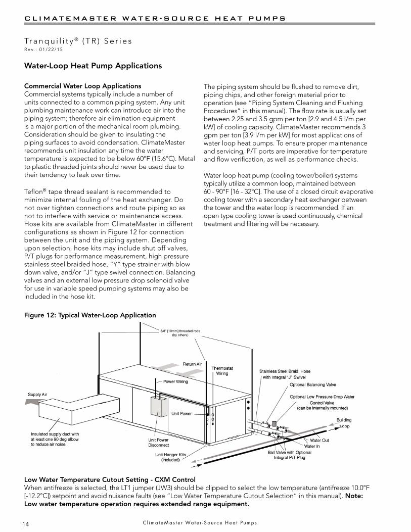
Water-Loop Heat Pump Applications
Commercial Water Loop ApplicationsCommercial systems typically include a number of units connected to a common piping system. Any unit plumbing maintenance work can introduce air into the piping system; therefore air elimination equipment is a major portion of the mechanical room plumbing. Consideration should be given to insulating the piping surfaces to avoid condensation. ClimateMaster recommends unit insulation any time the water temperature is expected to be below 60ºF (15.6ºC). Metal to plastic threaded joints should never be used due to their tendency to leak over time.
Teflon® tape thread sealant is recommended to minimize internal fouling of the heat exchanger. Do not over tighten connections and route piping so as not to interfere with service or maintenance access. Hose kits are available from ClimateMaster in different configurations as shown in Figure 12 for connection between the unit and the piping system. Depending upon selection, hose kits may include shut off valves, P/T plugs for performance measurement, high pressure stainless steel braided hose, “Y” type strainer with blow down valve, and/or “J” type swivel connection. Balancing valves and an external low pressure drop solenoid valve for use in variable speed pumping systems may also be included in the hose kit.
The piping system should be flushed to remove dirt, piping chips, and other foreign material prior to operation (see “Piping System Cleaning and Flushing Procedures” in this manual). The flow rate is usually set between 2.25 and 3.5 gpm per ton [2.9 and 4.5 l/m per kW] of cooling capacity. ClimateMaster recommends 3 gpm per ton [3.9 l/m per kW] for most applications of water loop heat pumps. To ensure proper maintenance and servicing, P/T ports are imperative for temperature and flow verification, as well as performance checks.
Water loop heat pump (cooling tower/boiler) systems typically utilize a common loop, maintained between 60 - 90°F [16 - 32°C]. The use of a closed circuit evaporative cooling tower with a secondary heat exchanger between the tower and the water loop is recommended. If an open type cooling tower is used continuously, chemical treatment and filtering will be necessary.
Figure 12: Typical Water-Loop Application
3/8" [10mm] threaded rods(by others)
Low Water Temperature Cutout Setting - CXM Control When antifreeze is selected, the LT1 jumper (JW3) should be clipped to select the low temperature (antifreeze 10.0°F [-12.2°C]) setpoint and avoid nuisance faults (see “Low Water Temperature Cutout Selection” in this manual). Note: Low water temperature operation requires extended range equipment.
15
THE SMART SOLUTION FOR ENERGY EFFICIENCY
Tr a n q u i l i t y ® ( T R ) S e r i e sR e v. : 0 1 / 2 2 / 1 5
c l i m a t e m a s t e r . c o m
Ground-Loop Heat Pump Applications
Pre-InstallationPrior to installation, locate and mark all existing underground utilities, piping, etc. Install loops for new construction before sidewalks, patios, driveways, and other construction has begun. During construction, accurately mark all ground loop piping on the plot plan as an aid in avoiding potential future damage to the installation.
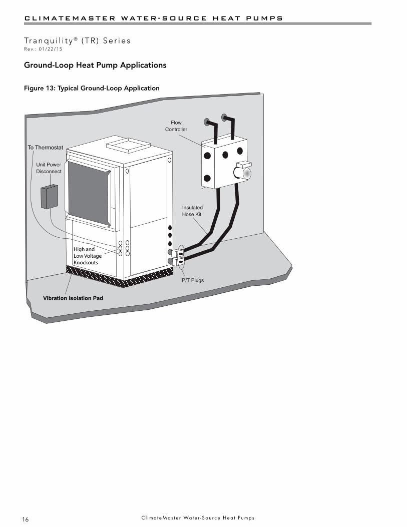
Piping InstallationThe typical closed loop ground source system is shown in Figure 13. All earth loop piping materials should be limited to polyethylene fusion only for in-ground sections of the loop. Galvanized or steel fittings should not be used at any time due to their tendency to corrode. All plastic to metal threaded fittings should be avoided due to their potential to leak in earth coupled applications. A flanged fitting should be substituted. P/T plugs should be used so that flow can be measured using the pressure drop of the unit heat exchanger.
Earth loop temperatures can range between 25 and 110°F [-4 to 43°C]. Flow rates between 2.25 and 3 gpm [2.41 to 3.23 l/m per kW] of cooling capacity is recommended in these applications.
Test individual horizontal loop circuits before backfilling. Test vertical U-bends and pond loop assemblies prior to installation. Pressures of at least 100 psi [689 kPa] should be used when testing. Do not exceed the pipe pressure rating. Test entire system when all loops are assembled.
Flushing the Earth LoopUpon completion of system installation and testing, flush the system to remove all foreign objects and purge to remove all air.
AntifreezeIn areas where minimum entering loop temperatures drop below 40°F [5°C] or where piping will be routed through areas subject to freezing, antifreeze is required. Alcohols and glycols are commonly used as antifreeze; however your local sales office should be consulted to determine the antifreeze best suited to your area. Freeze protection should be maintained to 15°F [9°C] below the lowest expected entering loop temperature. For example, if 30°F [-1°C] is the minimum expected entering loop temperature, the leaving loop temperature would be 22 to 25°F [-6 to -4°C] and freeze protection should be at 15°F [-10°C]. Calculation is as follows:30°F - 15°F = 15°F [-1°C - 9°C = -10°C].
All alcohols should be premixed and pumped from a reservoir outside of the building when possible or introduced under the water level to prevent fumes. Calculate the total volume of fluid in the piping system. Then use the percentage by volume shown in table 2 for the amount of antifreeze needed. Antifreeze concentration should be checked from a well mixed sample using a hydrometer to measure specific gravity.
CAUTION! The following instructions represent industry accepted installation practices for closed loop earth coupled heat pump systems. Instructions are provided to assist the contractor in installing trouble free ground loops. These instructions are recommendations only. State/provincial and local codes MUST be followed and installation MUST conform to ALL applicable codes. It is the responsibility of the installing contractor to determine and comply with ALL applicable codes and regulations.
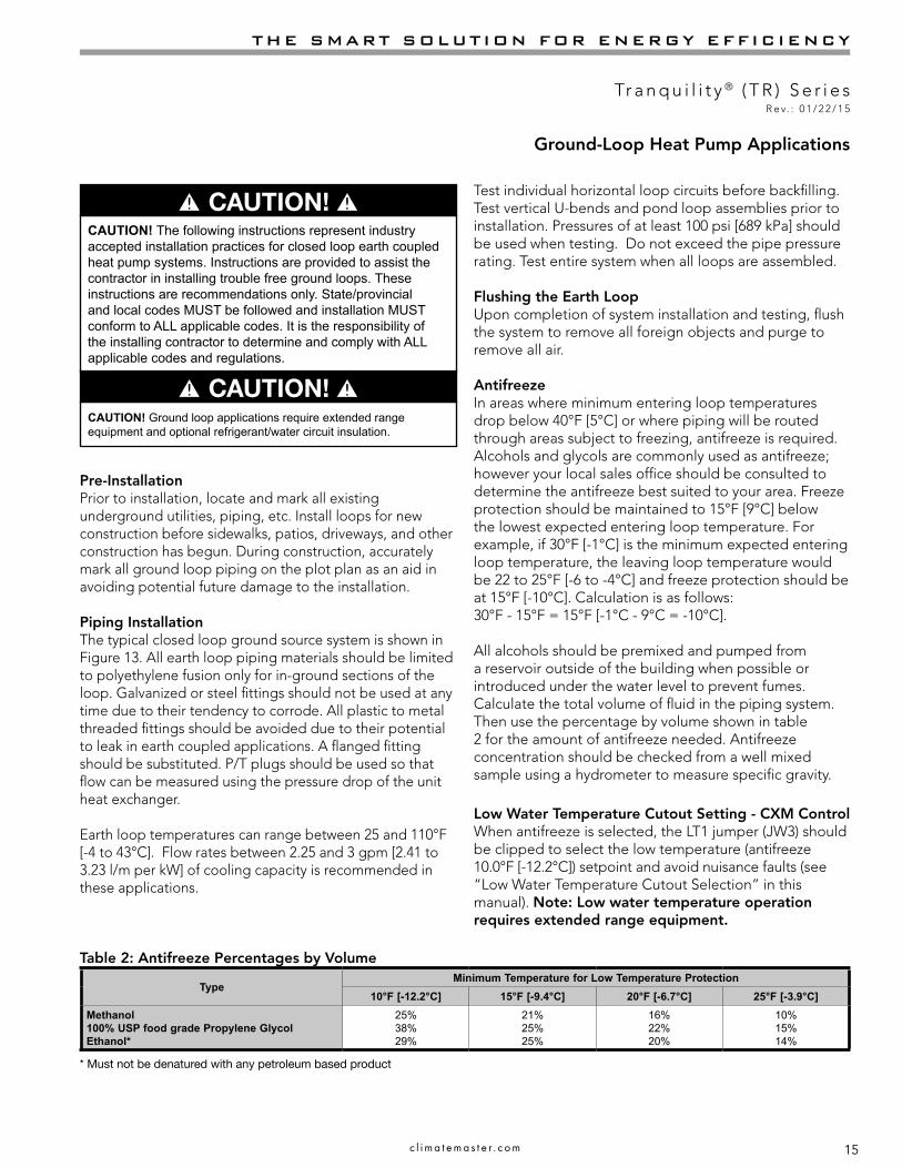
Table 2: Antifreeze Percentages by Volume
Low Water Temperature Cutout Setting - CXM Control When antifreeze is selected, the LT1 jumper (JW3) should be clipped to select the low temperature (antifreeze 10.0°F [-12.2°C]) setpoint and avoid nuisance faults (see “Low Water Temperature Cutout Selection” in this manual). Note: Low water temperature operation requires extended range equipment.
� CAUTION! �
� CAUTION! �
TypeMinimum Temperature for Low Temperature Protection
* Must not be denatured with any petroleum based product
CAUTION! Ground loop applications require extended range equipment and optional refrigerant/water circuit insulation.
16
CLIMATEMASTER WATER-SOURCE HEAT PUMPS
Tr a n q u i l i t y ® ( T R ) S e r i e sR e v. : 0 1 / 2 2 / 1 5
C l i m a t e M a s t e r Wa t e r - S o u r c e H e a t P u m p s
Ground-Loop Heat Pump Applications
Figure 13: Typical Ground-Loop Application
High and Low Voltage Knockouts
Vibration Isolation Pad
To Thermostat
17
THE SMART SOLUTION FOR ENERGY EFFICIENCY
Tr a n q u i l i t y ® ( T R ) S e r i e sR e v. : 0 1 / 2 2 / 1 5
c l i m a t e m a s t e r . c o m
Ground-Water Heat Pump Applications
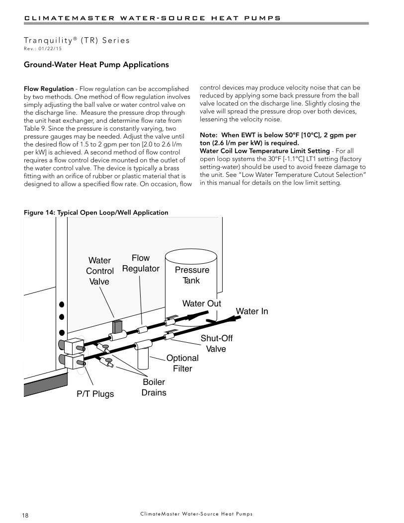
Open Loop - Ground Water Systems - Typical open loop piping is shown in Figure 14. Shut off valves should be included for ease of servicing. Boiler drains or other valves should be “tee’d” into the lines to allow acid flushing of the heat exchanger. Shut off valves should be positioned to allow flow through the coax via the boiler drains without allowing flow into the piping system. P/T plugs should be used so that pressure drop and temperature can be measured. Supply and return water piping materials should be limited to copper, PE, or similar material. PVC or CPVC should never be used as they are incompatible with the POE oils used in HFC-410A products and piping system failure and property damage may result.
Water quantity should be plentiful and of good quality. Consult table 3 for water quality guidelines. The unit can be ordered with either a copper or cupro-nickel water heat exchanger. Consult Table 3 for recommendations. Copper is recommended for closed loop systems and open loop ground water systems that are not high in mineral content or corrosiveness. In conditions anticipating heavy scale formation or in brackish water, a cupro-nickel heat exchanger is recommended. In ground water situations where scaling could be heavy or where biological growth such as iron bacteria will be present, an open loop system is not recommended. Heat exchanger coils may over time lose heat exchange capabilities due to build up of mineral deposits. Heat exchangers must only be serviced by a qualified technician, as acid and special pumping equipment is required. Desuperheater coils can likewise become scaled and possibly plugged. In areas with extremely hard water, the owner should be informed that the heat exchanger may require occasional acid flushing. In some cases, the desuperheater option should not be recommended due to hard water conditions and additional maintenance required.
WARNING! Polyolester Oil, commonly known as POE oil, is a synthetic oil used in many refrigeration systems including those with HFC-410A refrigerant. POE oil, if it ever comes in contact with PVC or CPVC piping, may cause failure of the PVC/CPVC. PVC/CPVC piping should never be used as supply or return water piping with water source heat pump products containing HFC-410A as system failures and property damage may result.
� WARNING! �
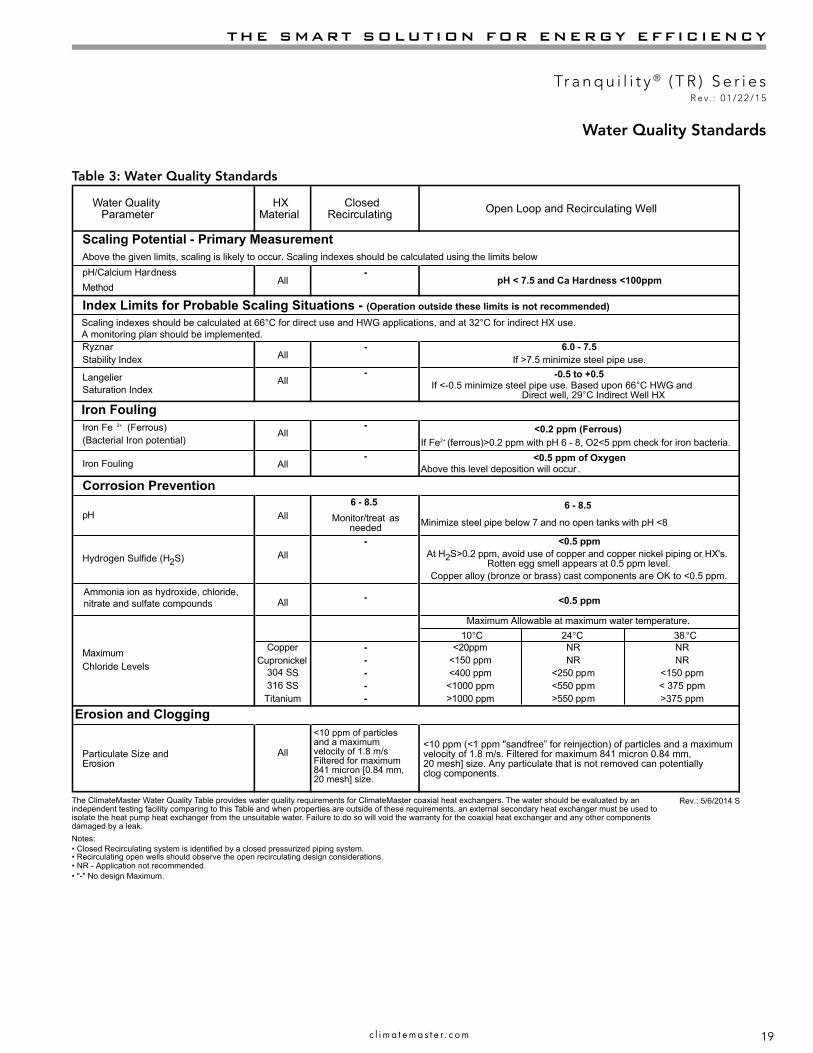
Water Quality Standards - Table 3 should be consulted for water quality requirements. Scaling potential should be assessed using the pH/Calcium hardness method. If the pH <7.5 and the calcium hardness is less than 100 ppm, scaling potential is low. If this method yields numbers out of range of those listed, the Ryznar Stability and Langelier Saturation indecies should be calculated. Use the appropriate scaling surface temperature for the application, 150°F [66°C] for direct use (well water/open loop) and DHW (desuperheater); 90°F [32°F] for indirect use. A monitoring plan should be implemented in these probable scaling situations. Other water quality issues such as iron fouling, corrosion prevention and erosion and clogging should be referenced in Table 3.
Expansion Tank and Pump - Use a closed, bladder-type expansion tank to minimize mineral formation due to air exposure. The expansion tank should be sized to provide at least one minute continuous run time of the pump using its drawdown capacity rating to prevent pump short cycling. Discharge water from the unit is not contaminated in any manner and can be disposed of in various ways, depending on local building codes (e.g. recharge well, storm sewer, drain field, adjacent stream or pond, etc.). Most local codes forbid the use of sanitary sewer for disposal. Consult your local building and zoning department to assure compliance in your area.
Water Control Valve - Note the placement of the water control valve in Figure 14. Always maintain water pressure in the heat exchanger by placing the water control valve(s) on the discharge line to prevent mineral precipitation during the off-cycle. Pilot operated slow closing valves are recommended to reduce water hammer. If water hammer persists, a mini-expansion tank can be mounted on the piping to help absorb the excess hammer shock. Ensure that the total ‘VA’ draw of the valve can be supplied by the unit transformer. For instance, a slow closing valve can draw up to 35VA. This can overload smaller 40 or 50 VA transformers depending on the other controls in the circuit. A typical pilot operated solenoid valve draws approximately 15VA (see Figure 19). Note the special wiring diagrams for slow closing valves (Figures 20 & 21).
18
CLIMATEMASTER WATER-SOURCE HEAT PUMPS
Tr a n q u i l i t y ® ( T R ) S e r i e sR e v. : 0 1 / 2 2 / 1 5
C l i m a t e M a s t e r Wa t e r - S o u r c e H e a t P u m p s
Figure 14: Typical Open Loop/Well Application
Tanque dePresión
Válvulade Retención
Drenajesde Caldera
Reguladorde Flujo
Entradade Agua
Salida de Agua
Válvula
FiltroOpcional
Tapones P/T
VibrationIsolation Pad
Unit PowerDisconnect
High and lowvoltage knockouts
PressureTank
Shut-OffValve
BoilerDrains
FlowRegulator
Water InWater Out
WaterControlValve
OptionalFilter
P/T Plugs
To Thermostat
Ground-Water Heat Pump Applications
Flow Regulation - Flow regulation can be accomplished by two methods. One method of flow regulation involves simply adjusting the ball valve or water control valve on the discharge line. Measure the pressure drop through the unit heat exchanger, and determine flow rate from Table 9. Since the pressure is constantly varying, two pressure gauges may be needed. Adjust the valve until the desired flow of 1.5 to 2 gpm per ton [2.0 to 2.6 l/m per kW] is achieved. A second method of flow control requires a flow control device mounted on the outlet of the water control valve. The device is typically a brass fitting with an orifice of rubber or plastic material that is designed to allow a specified flow rate. On occasion, flow
control devices may produce velocity noise that can be reduced by applying some back pressure from the ball valve located on the discharge line. Slightly closing the valve will spread the pressure drop over both devices, lessening the velocity noise.
Note: When EWT is below 50°F [10°C], 2 gpm per ton (2.6 l/m per kW) is required.Water Coil Low Temperature Limit Setting - For all open loop systems the 30°F [-1.1°C] LT1 setting (factory setting-water) should be used to avoid freeze damage to the unit. See “Low Water Temperature Cutout Selection” in this manual for details on the low limit setting.
19
THE SMART SOLUTION FOR ENERGY EFFICIENCY
Tr a n q u i l i t y ® ( T R ) S e r i e sR e v. : 0 1 / 2 2 / 1 5
c l i m a t e m a s t e r . c o m
Water Quality Standards
Table 3: Water Quality Standards
Water QualityParameter
HXMaterial
ClosedRecirculating Open Loop and Recirculating Well
Scaling Potential - Primary Measurement
pH/Calcium HardnessAll
-pH < 7.5 and Ca Hardness <100ppm
Method
Index Limits for Probable Scaling Situations - (Operation outside these limits is not recommended)
RyznarAll
- 6.0 - 7.5Stability Index If >7.5 minimize steel pipe use.
Langelier All- -0.5 to +0.5
Saturation Index If <-0.5 minimize steel pipe use. Based upon 66°C HWG andDirect well, 29°C Indirect Well HX
Iron FoulingIron Fe 2+ (Ferrous) All
- <0.2 ppm (Ferrous)(Bacterial Iron potential) If Fe2+ (ferrous)>0.2 ppm with pH 6 - 8, O2<5 ppm check for iron bacteria.
Iron Fouling All- <0.5 ppm of Oxygen
Above this level deposition will occur .
Corrosion Prevention
pH All6 - 8.5 6 - 8.5
Monitor/treat asneeded Minimize steel pipe below 7 and no open tanks with pH <8
Hydrogen Sulfide (H2S) All- <0.5 ppm
At H2S>0.2 ppm, avoid use of copper and copper nickel piping or HX's.Rotten egg smell appears at 0.5 ppm level.
Copper alloy (bronze or brass) cast components are OK to <0.5 ppm.Ammonia ion as hydroxide, chloride, nitrate and sulfate compounds All - <0.5 ppm
Maximum
Maximum Allowable at maximum water temperature.
Chloride Levels
10°C 24°C 38 CCopper
Cupronickel- <20ppm NR NR- <150 ppm NR NR
304 SS - <400 ppm <250 ppm <150 ppm316 SS - <1000 ppm <550 ppm < 375 ppm
Titanium - >1000 ppm >550 ppm >375 ppm
Erosion and Clogging
Particulate Size andErosion
All
<10 ppm of particlesand a maximumvelocity of 1.8 m/sFiltered for maximum841 micron [0.84 mm,20 mesh] size.
<10 ppm (<1 ppm "sandfree” for reinjection) of particles and a maximum velocity of 1.8 m/s. Filtered for maximum 841 micron 0.84 mm,20 mesh] size. Any particulate that is not removed can potentiallyclog components.
Notes:
Rev.: 5/6/2014 S
• NR - Application not recommended.• "-" No design Maximum.
• Closed Recirculating system is identified by a closed pressurized piping system.• Recirculating open wells should observe the open recirculating design considerations.
Above the given limits, scaling is likely to occur. Scaling indexes should be calculated using the limits below
Scaling indexes should be calculated at 66°C for direct use and HWG applications, and at 32°C for indirect HX use. A monitoring plan should be implemented.
The ClimateMaster Water Quality Table provides water quality requirements for ClimateMaster coaxial heat exchangers. The water should be evaluated by an independent testing facility comparing to this Table and when properties are outside of these requirements, an external secondary heat exchanger must be used to isolate the heat pump heat exchanger from the unsuitable water. Failure to do so will void the warranty for the coaxial heat exchanger and any other components damaged by a leak.
20
CLIMATEMASTER WATER-SOURCE HEAT PUMPS
Tr a n q u i l i t y ® ( T R ) S e r i e sR e v. : 0 1 / 2 2 / 1 5
C l i m a t e M a s t e r Wa t e r - S o u r c e H e a t P u m p s
Electrical - Line Voltage
Electrical - Line Voltage - All field installed wiring, including electrical ground, must comply with the National Electrical Code as well as all applicable local codes. Refer to the unit electrical data for fuse sizes. Consult wiring diagram for field connections that must be made by the installing (or electrical) contractor. All final electrical connections must be made with a length of flexible conduit to minimize vibration and sound transmission to the building.
General Line Voltage Wiring - Be sure the available power is the same voltage and phase shown on the unit serial plate. Line and low voltage wiring must be done in accordance with local codes or the National Electric Code, whichever is applicable.
WARNING! To avoid possible injury or death due to electrical shock, open the power supply disconnect switch and secure it in an open position during installation.
CAUTION! Use only copper conductors for field installed electrical wiring. Unit terminals are not designed to accept other types of conductors.
� WARNING! �
� CAUTION! �
Transformer - All 208/230 voltage units are factory wired for 208 volt. If supply voltage is 230 volt, installer must rewire transformer. See wire diagram for connections.
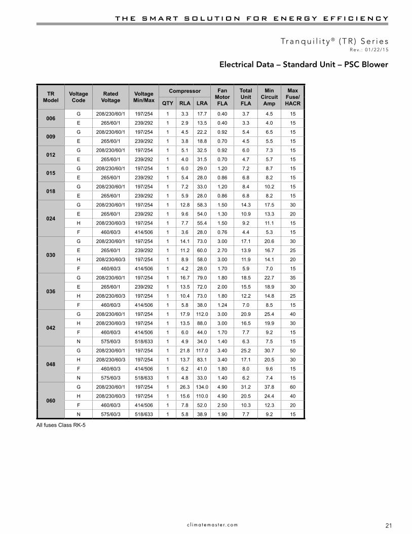
21
THE SMART SOLUTION FOR ENERGY EFFICIENCY
Tr a n q u i l i t y ® ( T R ) S e r i e sR e v. : 0 1 / 2 2 / 1 5
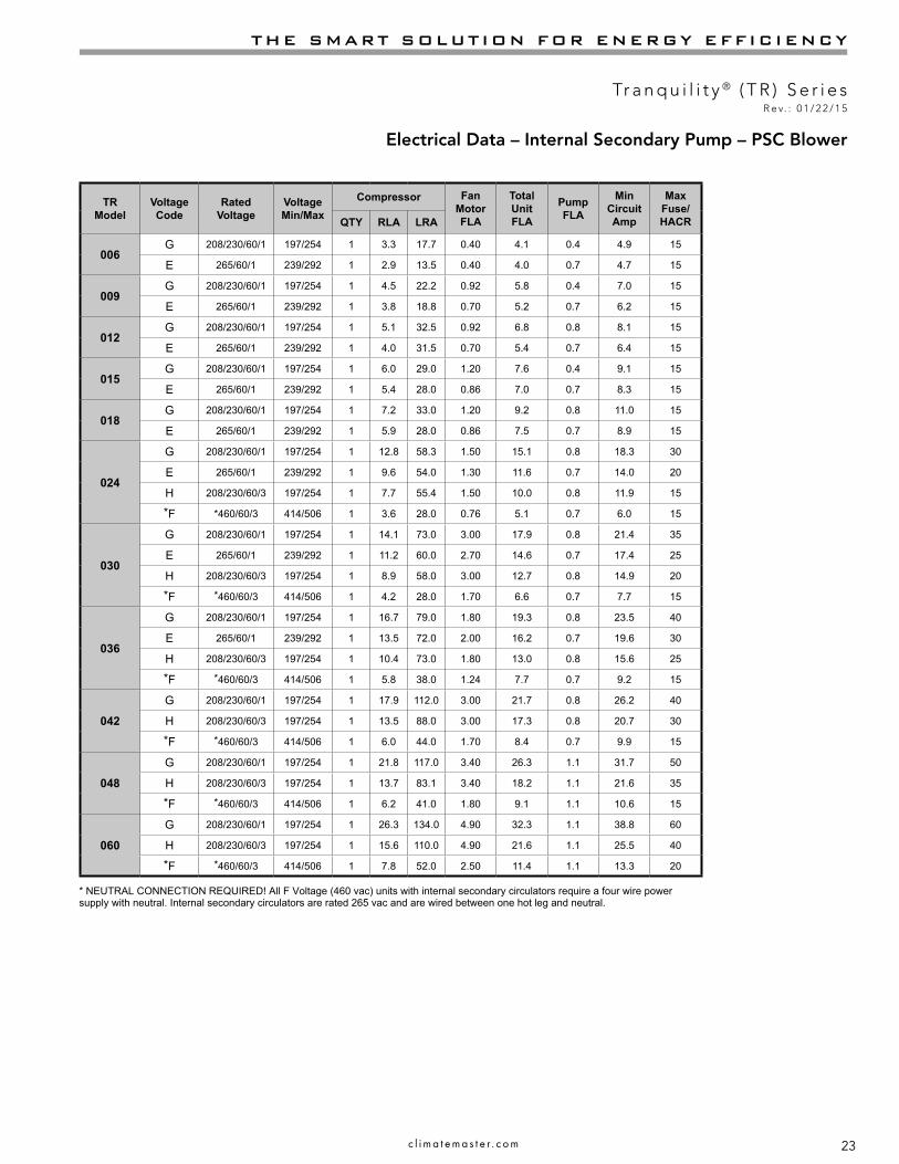
* NEUTRAL CONNECTION REQUIRED! All F Voltage (460 vac) units with internal secondary circulators require a four wire power supply with neutral. Internal secondary circulators are rated 265 vac and are wired between one hot leg and neutral.
Electrical Data – Internal Secondary Pump – PSC Blower
24
CLIMATEMASTER WATER-SOURCE HEAT PUMPS
Tr a n q u i l i t y ® ( T R ) S e r i e sR e v. : 0 1 / 2 2 / 1 5
C l i m a t e M a s t e r Wa t e r - S o u r c e H e a t P u m p s
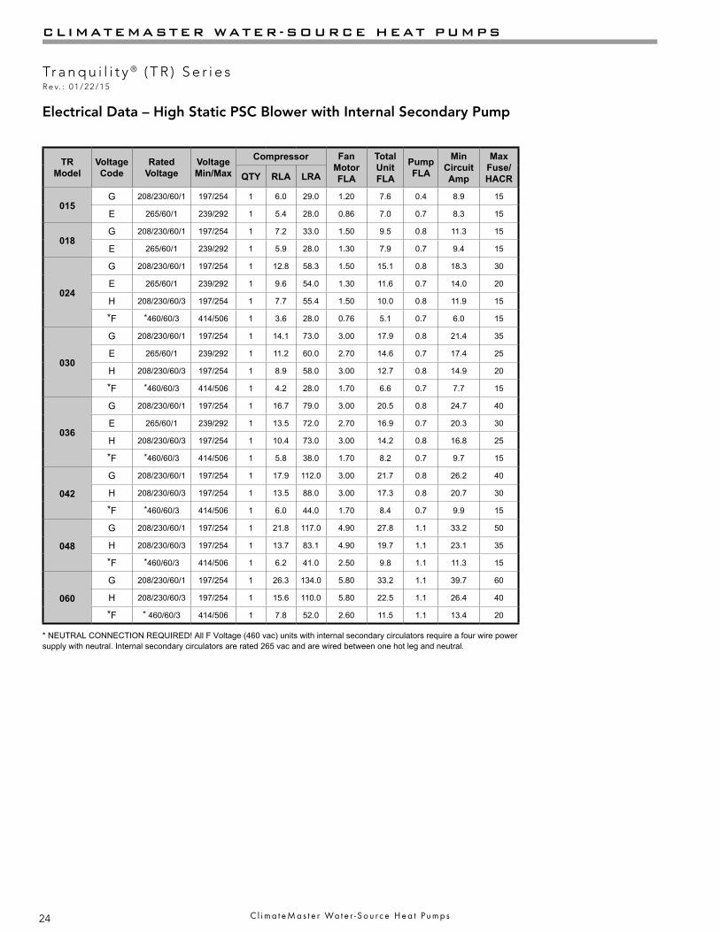
* NEUTRAL CONNECTION REQUIRED! All F Voltage (460 vac) units with internal secondary circulators require a four wire power supply with neutral. Internal secondary circulators are rated 265 vac and are wired between one hot leg and neutral.
Electrical Data – High Static PSC Blower with Internal Secondary Pump
25
THE SMART SOLUTION FOR ENERGY EFFICIENCY
Tr a n q u i l i t y ® ( T R ) S e r i e sR e v. : 0 1 / 2 2 / 1 5
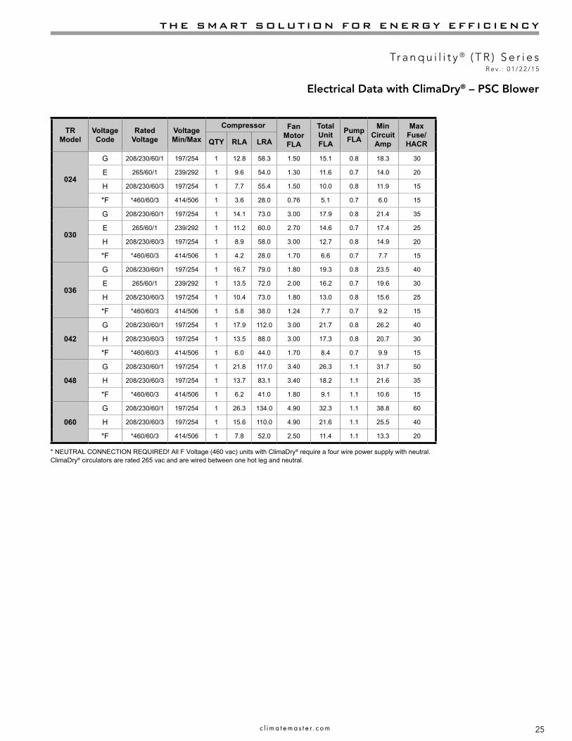
* NEUTRAL CONNECTION REQUIRED! All F Voltage (460 vac) units with ClimaDry® require a four wire power supply with neutral. ClimaDry® circulators are rated 265 vac and are wired between one hot leg and neutral.
Electrical Data with ClimaDry® – PSC Blower
26
CLIMATEMASTER WATER-SOURCE HEAT PUMPS
Tr a n q u i l i t y ® ( T R ) S e r i e sR e v. : 0 1 / 2 2 / 1 5
C l i m a t e M a s t e r Wa t e r - S o u r c e H e a t P u m p s
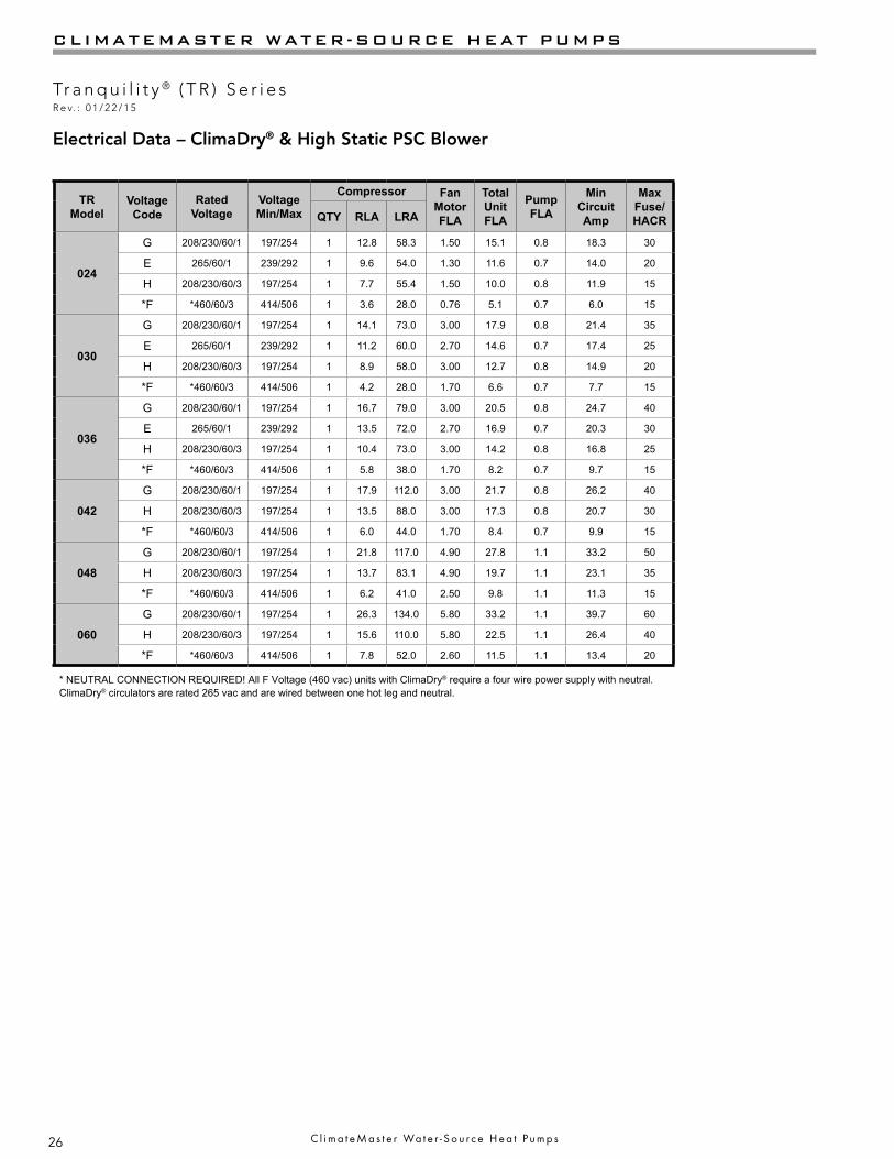
Electrical Data – ClimaDry® & High Static PSC Blower
* NEUTRAL CONNECTION REQUIRED! All F Voltage (460 vac) units with ClimaDry® require a four wire power supply with neutral. ClimaDry® circulators are rated 265 vac and are wired between one hot leg and neutral.
27
THE SMART SOLUTION FOR ENERGY EFFICIENCY
Tr a n q u i l i t y ® ( T R ) S e r i e sR e v. : 0 1 / 2 2 / 1 5
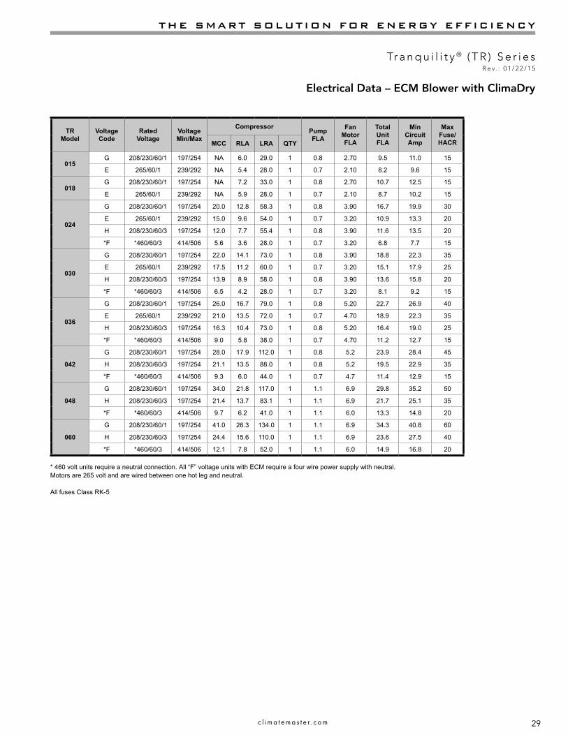
G 208/230/60/1 197/254 12.8 58.3 1 3.90 16.7 19.9 30
E 265/60/1 239/292 9.6 54.0 1 3.20 12.8 15.2 20
H 208/230/60/3 197/254 7.7 55.4 1 3.90 11.6 13.5 20
*F *460/60/3 414/506 3.6 28.0 1 3.20 6.8 7.7 15
030
G 208/230/60/1 197/254 14.1 73.0 1 3.90 18.0 21.5 35
E 265/60/1 239/292 11.2 60.0 1 3.20 14.4 17.2 25
H 208/230/60/3 197/254 8.9 58.0 1 3.90 12.8 15.0 20
*F *460/60/3 414/506 4.2 28.0 1 3.20 7.4 8.5 15
036
G 208/230/60/1 197/254 16.7 79.0 1 5.20 21.9 26.1 40
E 265/60/1 239/292 13.5 72.0 1 4.70 18.2 21.6 35
H 208/230/60/3 197/254 10.4 73.0 1 5.20 15.6 18.2 25
*F *460/60/3 414/506 5.8 38.0 1 4.70 10.5 12.0 15
042
G 208/230/60/1 197/254 17.9 112.0 1 5.20 23.1 27.6 45
H 208/230/60/3 197/254 13.5 88.0 1 5.20 18.7 22.1 35
*F *460/60/3 414/506 6.0 44.0 1 4.70 10.7 12.2 15
048
G 208/230/60/1 197/254 21.8 117.0 1 6.90 28.7 34.2 50
H 208/230/60/3 197/254 13.7 83.1 1 6.90 20.6 24.0 35
*F *460/60/3 414/506 6.2 41.0 1 6.00 12.2 13.8 20
060
G 208/230/60/1 197/254 26.3 134.0 1 6.90 33.2 39.8 60
H 208/230/60/3 197/254 15.6 110.0 1 6.90 22.5 26.4 40
*F *460/60/3 414/506 7.8 52.0 1 6.00 13.8 15.8 20
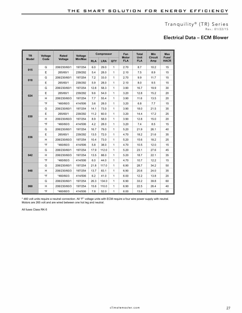
* 460 volt units require a neutral connection. All “F” voltage units with ECM require a four wire power supply with neutral. Motors are 265 volt and are wired between one hot leg and neutral.
All fuses Class RK-5
28
CLIMATEMASTER WATER-SOURCE HEAT PUMPS
Tr a n q u i l i t y ® ( T R ) S e r i e sR e v. : 0 1 / 2 2 / 1 5
C l i m a t e M a s t e r Wa t e r - S o u r c e H e a t P u m p s
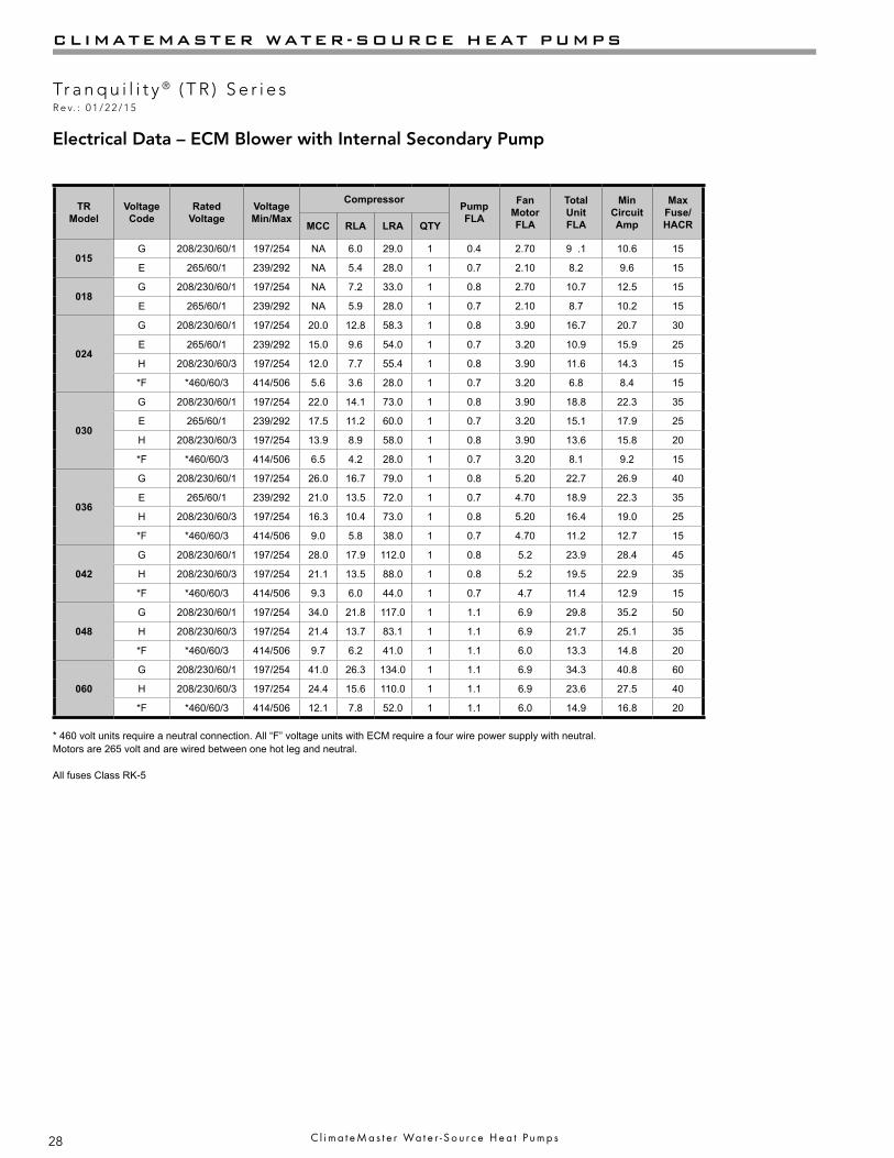
Electrical Data – ECM Blower with Internal Secondary Pump
* 460 volt units require a neutral connection. All “F” voltage units with ECM require a four wire power supply with neutral. Motors are 265 volt and are wired between one hot leg and neutral.
All fuses Class RK-5
29
THE SMART SOLUTION FOR ENERGY EFFICIENCY
Tr a n q u i l i t y ® ( T R ) S e r i e sR e v. : 0 1 / 2 2 / 1 5
* 460 volt units require a neutral connection. All “F” voltage units with ECM require a four wire power supply with neutral. Motors are 265 volt and are wired between one hot leg and neutral.
All fuses Class RK-5
30
CLIMATEMASTER WATER-SOURCE HEAT PUMPS
Tr a n q u i l i t y ® ( T R ) S e r i e sR e v. : 0 1 / 2 2 / 1 5
C l i m a t e M a s t e r Wa t e r - S o u r c e H e a t P u m p s
Electrical - Power Wiring
CAUTION! Use only copper conductors for field installed electrical wiring. Unit terminals are not designed to accept other types of conductors.
Electrical - Line Voltage - All field installed wiring, including electrical ground, must comply with the National Electrical Code as well as all applicable local codes. Refer to the unit electrical data for fuse sizes. Consult wiring diagram for field connections that must be made by the installing (or electrical) contractor. All final electrical connections must be made with a length of flexible conduit to minimize vibration and sound transmission to the building.
General Line Voltage Wiring - Be sure the available power is the same voltage and phase shown on the unit serial plate. Line and low voltage wiring must be done in accordance with local codes or the National Electric Code, whichever is applicable.
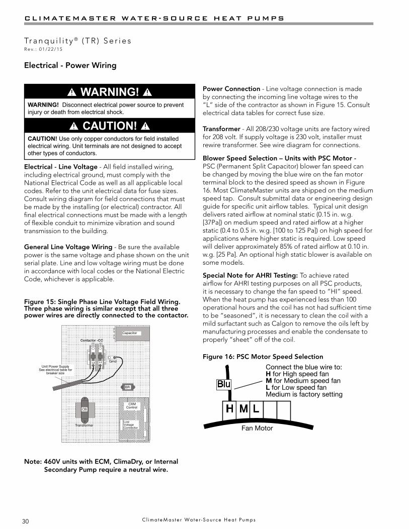
Figure 15: Single Phase Line Voltage Field Wiring. Three phase wiring is similar except that all three power wires are directly connected to the contactor.
Transformer
CXM Control
Contactor -CC
BR
Low VoltageConnector
CB
L2 L1
Unit Power SupplySee electrical table for
breaker size
Grnd
Rev.: 5/17/01 B
Capacitor
Blower Speed Selection – Units with PSC Motor - PSC (Permanent Split Capacitor) blower fan speed can be changed by moving the blue wire on the fan motor terminal block to the desired speed as shown in Figure 16. Most ClimateMaster units are shipped on the medium speed tap. Consult submittal data or engineering design guide for specific unit airflow tables. Typical unit design delivers rated airflow at nominal static (0.15 in. w.g. [37Pa]) on medium speed and rated airflow at a higher static (0.4 to 0.5 in. w.g. [100 to 125 Pa]) on high speed for applications where higher static is required. Low speed will deliver approximately 85% of rated airflow at 0.10 in. w.g. [25 Pa]. An optional high static blower is available on some models.
WARNING! Disconnect electrical power source to prevent injury or death from electrical shock.
� CAUTION! �
� WARNING! � Power Connection - Line voltage connection is made by connecting the incoming line voltage wires to the “L” side of the contractor as shown in Figure 15. Consult electrical data tables for correct fuse size.
Transformer - All 208/230 voltage units are factory wired for 208 volt. If supply voltage is 230 volt, installer must rewire transformer. See wire diagram for connections.
Special Note for AHRI Testing: To achieve rated airflow for AHRI testing purposes on all PSC products, it is necessary to change the fan speed to “HI” speed. When the heat pump has experienced less than 100 operational hours and the coil has not had sufficient time to be “seasoned”, it is necessary to clean the coil with a mild surfactant such as Calgon to remove the oils left by manufacturing processes and enable the condensate to properly “sheet” off of the coil.
H M L
Azul
Fan MotorMotor del Ventilador
Conectar el cable azul a:H para velocidad de ventilador altaM para velocidad de ventilador mediaL para velocidad de ventilador baja
La configuración de fábrica es velocidadmedia
Connect the blue wire to:H for High speed fanM for Medium speed fanL for Low speed fanMedium is factory setting
Fan Motor
Figure 16: PSC Motor Speed Selection
Note: 460V units with ECM, ClimaDry, or Internal Secondary Pump require a neutral wire.
31
THE SMART SOLUTION FOR ENERGY EFFICIENCY
Tr a n q u i l i t y ® ( T R ) S e r i e sR e v. : 0 1 / 2 2 / 1 5
c l i m a t e m a s t e r . c o m
CONTROL LAYOUTCAP
ECM
TRANS
GNDLL2
T2 T1
CC
Low voltage thermostat wiring units with PSC Fan
Low voltage thermostat wiring units with ECM Fan
Electrical - Power & Low Voltage Wiring
ELECTRICAL - LOW VOLTAGE WIRING
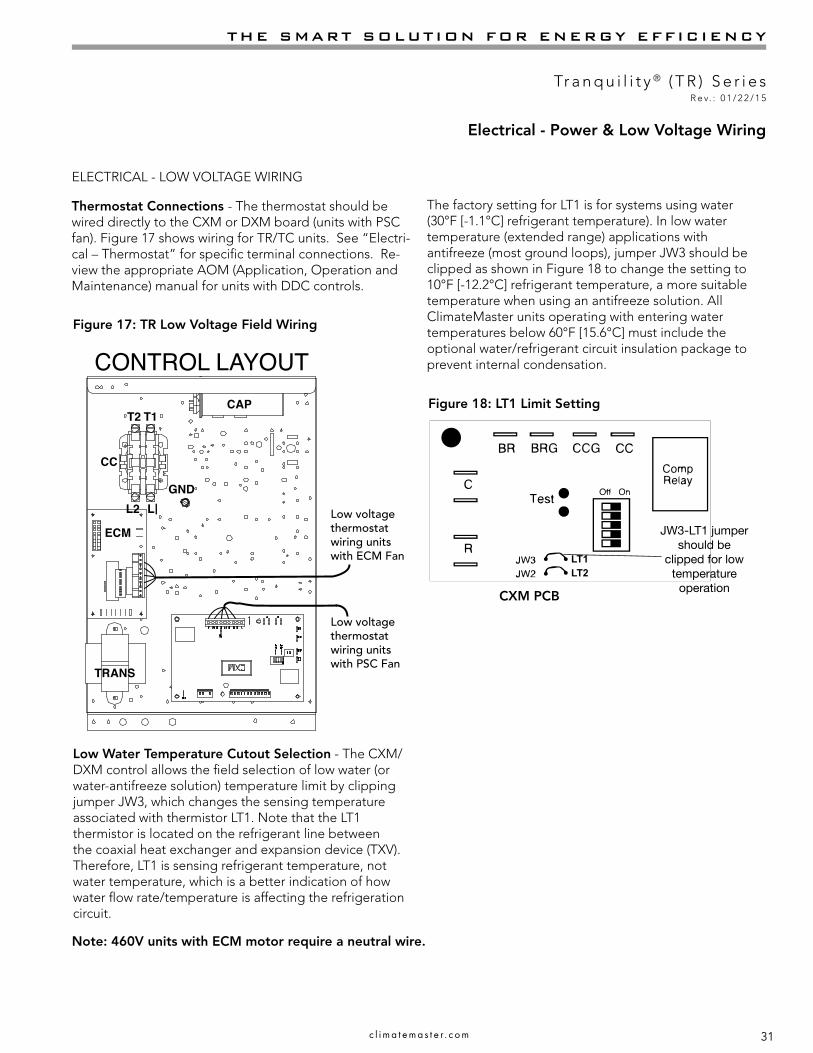
Figure 17: TR Low Voltage Field Wiring
Thermostat Connections - The thermostat should be wired directly to the CXM or DXM board (units with PSC fan). Figure 17 shows wiring for TR/TC units. See “Electri-cal – Thermostat” for specific terminal connections. Re-view the appropriate AOM (Application, Operation and Maintenance) manual for units with DDC controls.
Low Water Temperature Cutout Selection - The CXM/DXM control allows the field selection of low water (or water-antifreeze solution) temperature limit by clipping jumper JW3, which changes the sensing temperature associated with thermistor LT1. Note that the LT1 thermistor is located on the refrigerant line between the coaxial heat exchanger and expansion device (TXV). Therefore, LT1 is sensing refrigerant temperature, not water temperature, which is a better indication of how water flow rate/temperature is affecting the refrigeration circuit.
Figure 18: LT1 Limit Setting
CXM PCB
LT1LT2
LT1LT1LT2LT2
JW3-LT1 jumper should be
clipped for low temperature
operation
The factory setting for LT1 is for systems using water (30°F [-1.1°C] refrigerant temperature). In low water temperature (extended range) applications with antifreeze (most ground loops), jumper JW3 should be clipped as shown in Figure 18 to change the setting to 10°F [-12.2°C] refrigerant temperature, a more suitable temperature when using an antifreeze solution. All ClimateMaster units operating with entering water temperatures below 60°F [15.6°C] must include the optional water/refrigerant circuit insulation package to prevent internal condensation.
Note: 460V units with ECM motor require a neutral wire.
32
CLIMATEMASTER WATER-SOURCE HEAT PUMPS
Tr a n q u i l i t y ® ( T R ) S e r i e sR e v. : 0 1 / 2 2 / 1 5
C l i m a t e M a s t e r Wa t e r - S o u r c e H e a t P u m p s
Electrical - Low Voltage Wiring
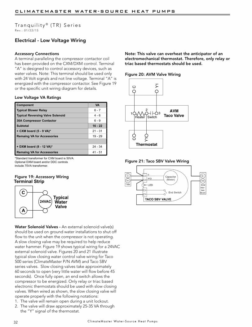
Accessory ConnectionsA terminal paralleling the compressor contactor coil has been provided on the CXM/DXM control. Terminal “A” is designed to control accessory devices, such as water valves. Note: This terminal should be used only with 24 Volt signals and not line voltage. Terminal “A” is energized with the compressor contactor. See Figure 19 or the specific unit wiring diagram for details.
Figure 19: Accessory Wiring
Water Solenoid Valves - An external solenoid valve(s) should be used on ground water installations to shut off flow to the unit when the compressor is not operating. A slow closing valve may be required to help reduce water hammer. Figure 19 shows typical wiring for a 24VAC external solenoid valve. Figures 20 and 21 illustrate typical slow closing water control valve wiring for Taco 500 series (ClimateMaster P/N AVM) and Taco SBV series valves. Slow closing valves take approximately 60 seconds to open (very little water will flow before 45 seconds). Once fully open, an end switch allows the compressor to be energized. Only relay or triac based electronic thermostats should be used with slow closing valves. When wired as shown, the slow closing valve will operate properly with the following notations:1. The valve will remain open during a unit lockout.2. The valve will draw approximately 25-35 VA through
the “Y” signal of the thermostat.
Low Voltage VA Ratings
Component VATypical Blower Relay 6 - 7
Typical Reversing Valve Solenoid 4 - 6
30A Compressor Contactor 6 - 9
Subtotal 16 - 22+ CXM board (5 - 9 VA)* 21 - 31
Remaing VA for Accessories 19 - 29
+ DXM board (8 - 12 VA)* 24 - 34
Remaing VA for Accessories 41 - 51
*Standard transformer for CXM board is 50VA.Optional DXM board and/or DDC controlsinclude 75VA transformer.
Figure 20: AVM Valve Wiring
Figure 21: Taco SBV Valve Wiring
CC
Termostato
Y
12
3
Y
AVMTaco VálvulaCalentador Interruptor
Unidad Empacada
CC
Thermostat
Y1
12
3
Y1
AVMTaco ValveHeater Switch
Note: This valve can overheat the anticipator of an electromechanical thermostat. Therefore, only relay or triac based thermostats should be used.
33
THE SMART SOLUTION FOR ENERGY EFFICIENCY
Tr a n q u i l i t y ® ( T R ) S e r i e sR e v. : 0 1 / 2 2 / 1 5
c l i m a t e m a s t e r . c o m
Electrical - Thermostat Wiring
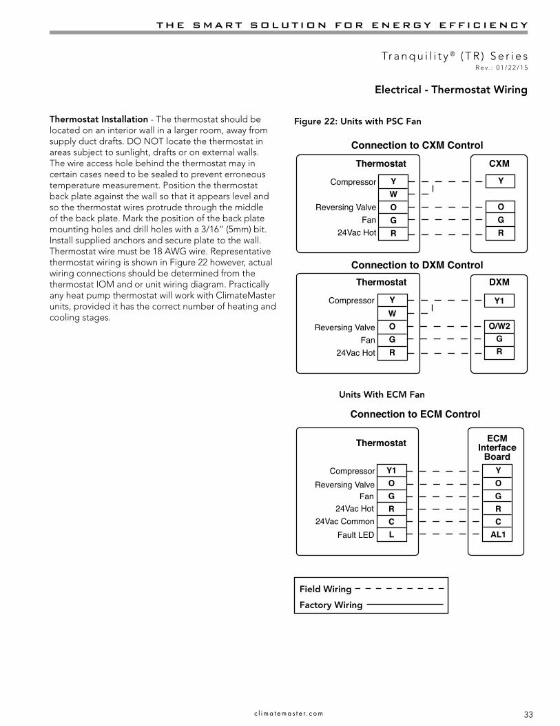
Thermostat Installation - The thermostat should be located on an interior wall in a larger room, away from supply duct drafts. DO NOT locate the thermostat in areas subject to sunlight, drafts or on external walls. The wire access hole behind the thermostat may in certain cases need to be sealed to prevent erroneous temperature measurement. Position the thermostat back plate against the wall so that it appears level and so the thermostat wires protrude through the middle of the back plate. Mark the position of the back plate mounting holes and drill holes with a 3/16” (5mm) bit. Install supplied anchors and secure plate to the wall. Thermostat wire must be 18 AWG wire. Representative thermostat wiring is shown in Figure 22 however, actual wiring connections should be determined from the thermostat IOM and or unit wiring diagram. Practically any heat pump thermostat will work with ClimateMaster units, provided it has the correct number of heating and cooling stages.
Figure 22: Units with PSC Fan
Field Wiring
Factory Wiring
Thermostat
Thermostat
Connection to CXM Control
Connection to DXM Control
Compressor
Reversing ValveFan
24Vac Hot
YWOGR
Y
OGR
CXM
Compressor
Reversing ValveFan
24Vac Hot
DXM
Y1
O/W2GR
YWOGR
Units With ECM Fan
Thermostat
Connection to ECM Control
CompressorReversing Valve
Fan24Vac Hot
24Vac CommonFault LED
Y1OGRCL
YOGRC
AL1
ECMInterface
Board
34
CLIMATEMASTER WATER-SOURCE HEAT PUMPS
Tr a n q u i l i t y ® ( T R ) S e r i e sR e v. : 0 1 / 2 2 / 1 5
C l i m a t e M a s t e r Wa t e r - S o u r c e H e a t P u m p s
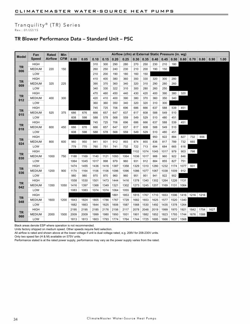
Black areas denote ESP where operation is not recommended.Units factory shipped on medium speed. Other speeds require field selection.All airflow is rated and shown above at the lower voltage if unit is dual voltage rated, e.g. 208V for 208-230V units.Only two speed fan (H & M) available on 575V units.Performance stated is at the rated power supply, performance may vary as the power supply varies from the rated.
TR Blower Performance Data – Standard Unit – PSC
35
THE SMART SOLUTION FOR ENERGY EFFICIENCY
Tr a n q u i l i t y ® ( T R ) S e r i e sR e v. : 0 1 / 2 2 / 1 5
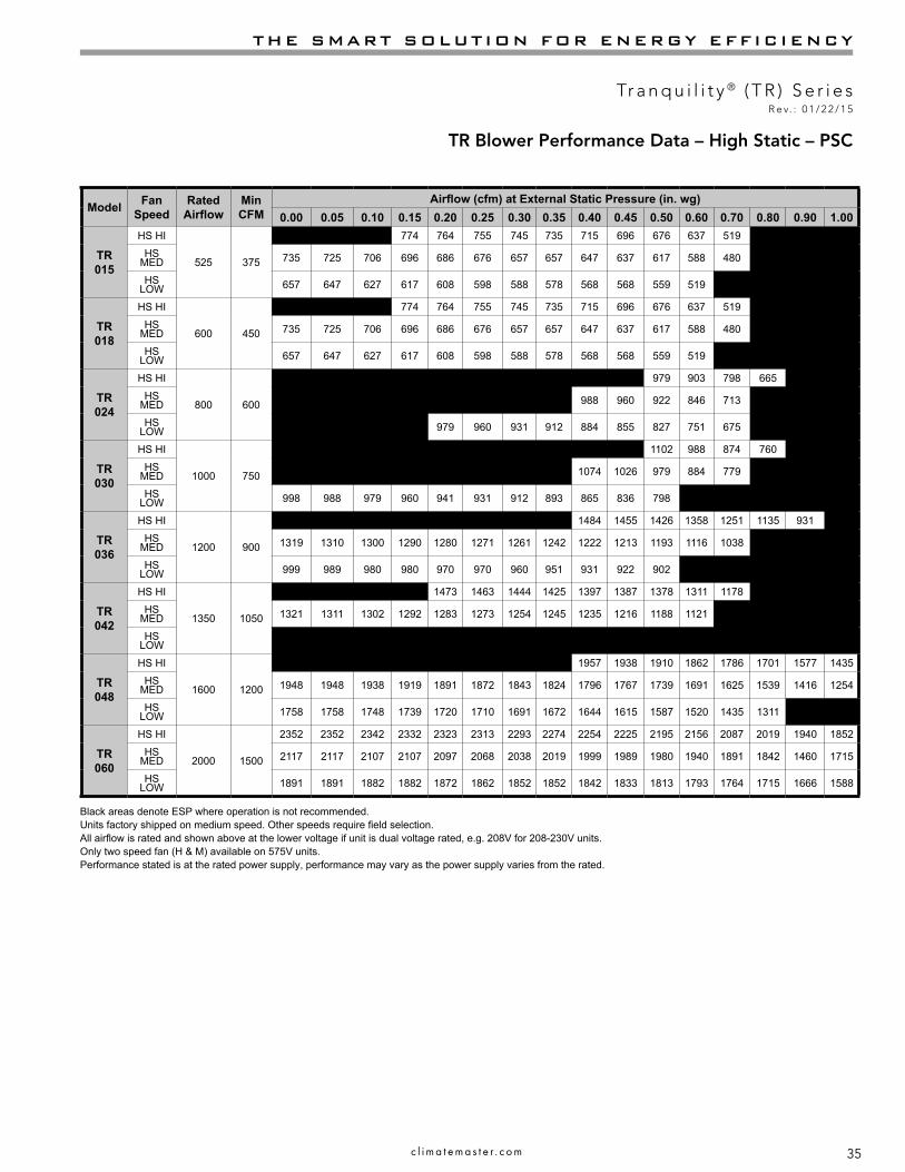
Black areas denote ESP where operation is not recommended.Units factory shipped on medium speed. Other speeds require field selection.All airflow is rated and shown above at the lower voltage if unit is dual voltage rated, e.g. 208V for 208-230V units.Only two speed fan (H & M) available on 575V units.Performance stated is at the rated power supply, performance may vary as the power supply varies from the rated.
TR Blower Performance Data – High Static – PSC
36
CLIMATEMASTER WATER-SOURCE HEAT PUMPS
Tr a n q u i l i t y ® ( T R ) S e r i e sR e v. : 0 1 / 2 2 / 1 5
C l i m a t e M a s t e r Wa t e r - S o u r c e H e a t P u m p s
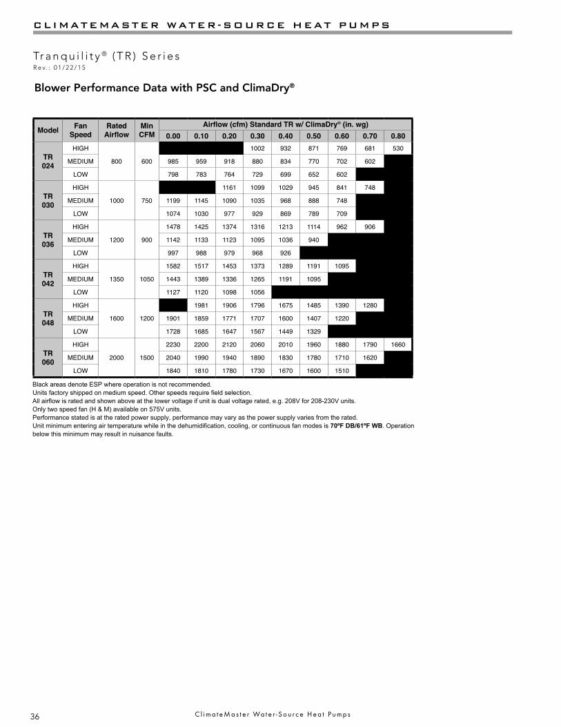
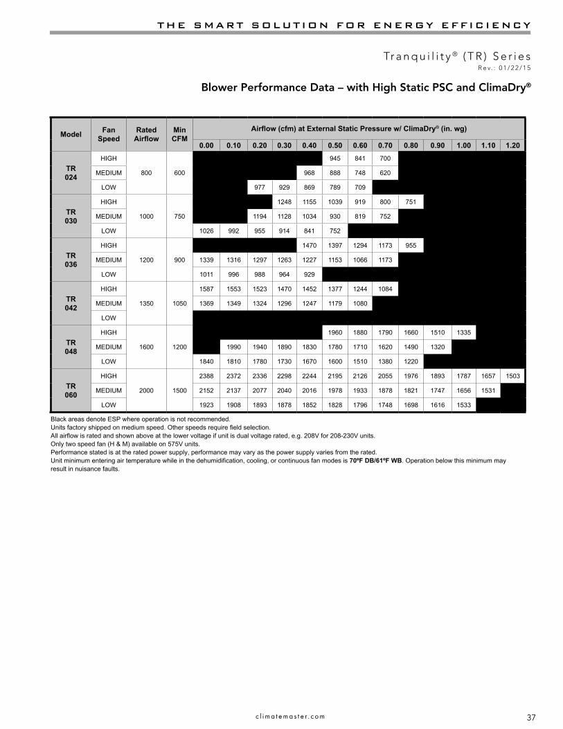
Black areas denote ESP where operation is not recommended.Units factory shipped on medium speed. Other speeds require field selection.All airflow is rated and shown above at the lower voltage if unit is dual voltage rated, e.g. 208V for 208-230V units.Only two speed fan (H & M) available on 575V units.Performance stated is at the rated power supply, performance may vary as the power supply varies from the rated.Unit minimum entering air temperature while in the dehumidification, cooling, or continuous fan modes is 70ºF DB/61ºF WB. Operation below this minimum may result in nuisance faults.
Blower Performance Data with PSC and ClimaDry®
37
THE SMART SOLUTION FOR ENERGY EFFICIENCY
Tr a n q u i l i t y ® ( T R ) S e r i e sR e v. : 0 1 / 2 2 / 1 5
c l i m a t e m a s t e r . c o m
Blower Performance Data – with High Static PSC and ClimaDry®
Model Fan Speed
Rated Airflow
Min CFM
Airflow (cfm) at External Static Pressure w/ ClimaDry® (in. wg)
Black areas denote ESP where operation is not recommended.Units factory shipped on medium speed. Other speeds require field selection.All airflow is rated and shown above at the lower voltage if unit is dual voltage rated, e.g. 208V for 208-230V units.Only two speed fan (H & M) available on 575V units.Performance stated is at the rated power supply, performance may vary as the power supply varies from the rated.Unit minimum entering air temperature while in the dehumidification, cooling, or continuous fan modes is 70ºF DB/61ºF WB. Operation below this minimum may result in nuisance faults.
38
CLIMATEMASTER WATER-SOURCE HEAT PUMPS
Tr a n q u i l i t y ® ( T R ) S e r i e sR e v. : 0 1 / 2 2 / 1 5
C l i m a t e M a s t e r Wa t e r - S o u r c e H e a t P u m p s
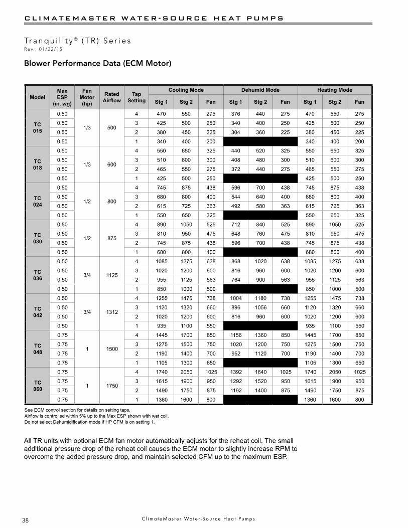
Blower Performance Data (ECM Motor)
ModelMax ESP
(in. wg)
Fan Motor (hp)
Rated Airflow
Tap Setting
Cooling Mode Dehumid Mode Heating Mode
Stg 1 Stg 2 Fan Stg 1 Stg 2 Fan Stg 1 Stg 2 Fan
TC 015
0.50
1/3 500
4 470 550 275 376 440 275 470 550 275
0.50 3 425 500 250 340 400 250 425 500 250
0.50 2 380 450 225 304 360 225 380 450 225
0.50 1 340 400 200 272 320 200 340 400 200
TC 018
0.50
1/3 600
4 550 650 325 440 520 325 550 650 325
0.50 3 510 600 300 408 480 300 510 600 300
0.50 2 465 550 275 372 440 275 465 550 275
0.50 1 425 500 250 340 400 250 425 500 250
TC 024
0.50
1/2 800
4 745 875 438 596 700 438 745 875 438
0.50 3 680 800 400 544 640 400 680 800 400
0.50 2 615 725 363 492 580 363 615 725 363
0.50 1 550 650 325 440 520 325 550 650 325
TC 030
0.50
1/2 875
4 890 1050 525 712 840 525 890 1050 525
0.50 3 810 950 475 648 760 475 810 950 475
0.50 2 745 875 438 596 700 438 745 875 438
0.50 1 680 800 400 544 640 400 680 800 400
TC 036
0.50
3/4 1125
4 1085 1275 638 868 1020 638 1085 1275 638
0.50 3 1020 1200 600 816 960 600 1020 1200 600
0.50 2 955 1125 563 764 900 563 955 1125 563
0.50 1 850 1000 500 680 800 500 850 1000 500
TC 042
0.50
3/4 1312
4 1255 1475 738 1004 1180 738 1255 1475 738
0.50 3 1120 1320 660 896 1056 660 1120 1320 660
0.50 2 1020 1200 600 816 960 600 1020 1200 600
0.50 1 935 1100 550 748 880 550 935 1100 550
TC 048
0.75
1 1500
4 1445 1700 850 1156 1360 850 1445 1700 850
0.75 3 1275 1500 750 1020 1200 750 1275 1500 750
0.75 2 1190 1400 700 952 1120 700 1190 1400 700
0.75 1 1105 1300 650 884 1040 650 1105 1300 650
TC 060
0.75
1 1750
4 1740 2050 1025 1392 1640 1025 1740 2050 1025
0.75 3 1615 1900 950 1292 1520 950 1615 1900 950
0.75 2 1490 1750 875 1192 1400 875 1490 1750 875
0.75 1 1360 1600 800 1088 1280 800 1360 1600 800
See ECM control section for details on setting taps.Airflow is controlled within 5% up to the Max ESP shown with wet coil.Do not select Dehumidification mode if HP CFM is on setting 1.
All TR units with optional ECM fan motor automatically adjusts for the reheat coil. The small additional pressure drop of the reheat coil causes the ECM motor to slightly increase RPM to overcome the added pressure drop, and maintain selected CFM up to the maximum ESP.
39
THE SMART SOLUTION FOR ENERGY EFFICIENCY
Tr a n q u i l i t y ® ( T R ) S e r i e sR e v. : 0 1 / 2 2 / 1 5
c l i m a t e m a s t e r . c o m
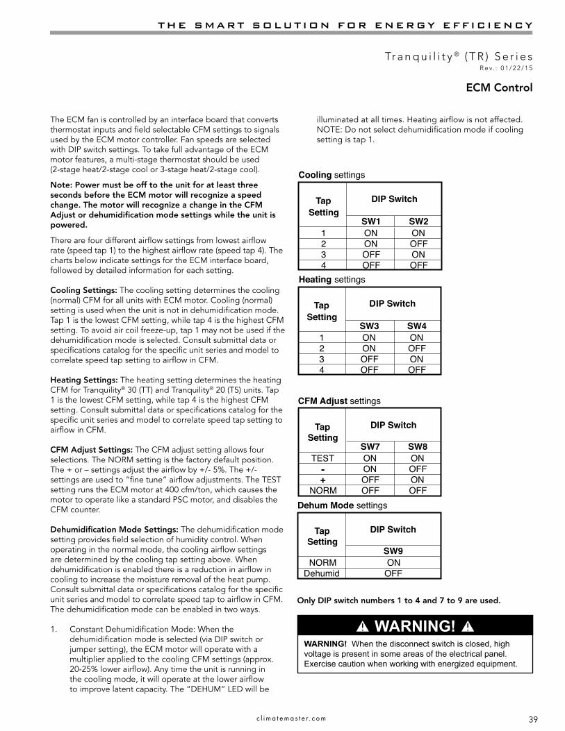
ECM Control
The ECM fan is controlled by an interface board that converts thermostat inputs and field selectable CFM settings to signals used by the ECM motor controller. Fan speeds are selected with DIP switch settings. To take full advantage of the ECM motor features, a multi-stage thermostat should be used (2-stage heat/2-stage cool or 3-stage heat/2-stage cool).
Note: Power must be off to the unit for at least three seconds before the ECM motor will recognize a speed change. The motor will recognize a change in the CFM Adjust or dehumidification mode settings while the unit is powered.
There are four different airflow settings from lowest airflow rate (speed tap 1) to the highest airflow rate (speed tap 4). The charts below indicate settings for the ECM interface board, followed by detailed information for each setting.
Cooling Settings: The cooling setting determines the cooling (normal) CFM for all units with ECM motor. Cooling (normal) setting is used when the unit is not in dehumidification mode. Tap 1 is the lowest CFM setting, while tap 4 is the highest CFM setting. To avoid air coil freeze-up, tap 1 may not be used if the dehumidification mode is selected. Consult submittal data or specifications catalog for the specific unit series and model to correlate speed tap setting to airflow in CFM.
Heating Settings: The heating setting determines the heating CFM for Tranquility® 30 (TT) and Tranquility® 20 (TS) units. Tap 1 is the lowest CFM setting, while tap 4 is the highest CFM setting. Consult submittal data or specifications catalog for the specific unit series and model to correlate speed tap setting to airflow in CFM.
CFM Adjust Settings: The CFM adjust setting allows four selections. The NORM setting is the factory default position. The + or – settings adjust the airflow by +/- 5%. The +/- settings are used to “fine tune” airflow adjustments. The TEST setting runs the ECM motor at 400 cfm/ton, which causes the motor to operate like a standard PSC motor, and disables the CFM counter.
Dehumidification Mode Settings: The dehumidification mode setting provides field selection of humidity control. When operating in the normal mode, the cooling airflow settings are determined by the cooling tap setting above. When dehumidification is enabled there is a reduction in airflow in cooling to increase the moisture removal of the heat pump. Consult submittal data or specifications catalog for the specific unit series and model to correlate speed tap to airflow in CFM. The dehumidification mode can be enabled in two ways. 1. Constant Dehumidification Mode: When the
dehumidification mode is selected (via DIP switch or jumper setting), the ECM motor will operate with a multiplier applied to the cooling CFM settings (approx. 20-25% lower airflow). Any time the unit is running in the cooling mode, it will operate at the lower airflow to improve latent capacity. The “DEHUM” LED will be
Only DIP switch numbers 1 to 4 and 7 to 9 are used.
WARNING! When the disconnect switch is closed, high voltage is present in some areas of the electrical panel. Exercise caution when working with energized equipment.
� WARNING! �
illuminated at all times. Heating airflow is not affected. NOTE: Do not select dehumidification mode if cooling setting is tap 1.
40
CLIMATEMASTER WATER-SOURCE HEAT PUMPS
Tr a n q u i l i t y ® ( T R ) S e r i e sR e v. : 0 1 / 2 2 / 1 5
C l i m a t e M a s t e r Wa t e r - S o u r c e H e a t P u m p s
2. Automatic (Humidistat-controlled) Dehumidification Mode: When the dehumidification mode is selected (via DIP switch or jumper setting) AND a humidistat is connected to terminal DH (version II) or HUM (version I), the cooling airflow will only be reduced when the humidistat senses that additional dehumidification is required. The DH (or HUM) terminal is reverse logic. Therefore, a humidistat (not dehumidistat) is required. The “DEHUM” LED will be illuminated only when the humidistat is calling for dehumidification mode. Heating airflow is not affected. NOTE: Do not select dehumidification mode if cooling setting is tap 1.
The ECM motor includes “soft start” and “ramp down” features. The soft start feature is a gentle increase of motor rpm at blower start up. This creates a much quieter blower start cycle.
The ramp down feature allows the blower to slowly decrease rpm to a full stop at the end of each blower cycle. This creates a much quieter end to each blower cycle and adds overall unit efficiency.
The ramp down feature may be eliminated during an ESD (Emergency Shut Down) situation when using a DXM unit controller. A DPDT relay is required to break the line voltage to the ECM motor during ESD. This relay can be wired as shown below to eliminate the ramp down (and operation) of the ECM blower motor.
To ‘ESD’ on DXM
To ‘R’ on DXM
ESD Signal(�eld input)
ECM Control
41
THE SMART SOLUTION FOR ENERGY EFFICIENCY
Tr a n q u i l i t y ® ( T R ) S e r i e sR e v. : 0 1 / 2 2 / 1 5
c l i m a t e m a s t e r . c o m
Typical Wiring Diagram – Single Phase TR Units with CXM Controller, ECM Blower
42
CLIMATEMASTER WATER-SOURCE HEAT PUMPS
Tr a n q u i l i t y ® ( T R ) S e r i e sR e v. : 0 1 / 2 2 / 1 5
C l i m a t e M a s t e r Wa t e r - S o u r c e H e a t P u m p s
Typical Wiring Diagram - Units with CXM Board and PSC Fan Motor (Single Phase)
43
THE SMART SOLUTION FOR ENERGY EFFICIENCY
Tr a n q u i l i t y ® ( T R ) S e r i e sR e v. : 0 1 / 2 2 / 1 5
c l i m a t e m a s t e r . c o m
Typical Wiring Diagram - Units with DXM Board and PSC Fan Motor (Three Phase)
44
CLIMATEMASTER WATER-SOURCE HEAT PUMPS
Tr a n q u i l i t y ® ( T R ) S e r i e sR e v. : 0 1 / 2 2 / 1 5
C l i m a t e M a s t e r Wa t e r - S o u r c e H e a t P u m p s
Typical Wiring Diagram – Single Phase TR with ClimaDry®
45
THE SMART SOLUTION FOR ENERGY EFFICIENCY
Tr a n q u i l i t y ® ( T R ) S e r i e sR e v. : 0 1 / 2 2 / 1 5
c l i m a t e m a s t e r . c o m
provides field selection to disable the UPS feature.On = Enabled. Off = Disabled.DIP switch 2: Stage 2 Selection - provides selection of whether compressor has an “on” delay. If set to stage 2, the compressor will have a 3 second delay before energizing. Also, if set for stage 2, the alarm relay will NOT cycle during test mode.On = Stage 1. Off = Stage 2DIP switch 3: Not Used.DIP switch 4: DDC Output at EH2 - provides selection for DDC operation. If set to “DDC Output at EH2,” the EH2 terminal will continuously output the last fault code of the controller. If set to “EH2 normal,” EH2 will operate as standard electric heat output.On = EH2 Normal. Off = DDC Output at EH2.Note: Some CXM controls only have a 2 position DIP switch package. If this is the case, this option can be selected by clipping the jumper which is in position 4 of SW1.Jumper not clipped = EH2 Normal. Jumper clipped = DDC Output at EH2.DIP switch 5: Factory Setting - Normal position is “On.”
CXM Controls
CXM Control - For detailed control information, see CXM Application, Operation and Maintenance (AOM) manual (part # 97B0003N12).
Field Selectable Inputs - Test mode: Test mode allows the service technician to check the operation of the control in a timely manner. At board, momentarily shorting the test terminals or externally, momentarily push test button (See Fig 10), the CXM control enters a 20 minute test mode period in which all time delays are sped up 15 times. Upon entering test mode, the status LED will flash a code representing the last fault. For diagnostic ease at the thermostat, the alarm relay will also cycle during test mode. The alarm relay will cycle on and off similar to the status LED to indicate a code representing the last fault, at the thermostat. Test mode can be exited by shorting the test terminals or holding button for 3 seconds.Retry Mode: If the control is attempting a retry of a fault, the status LED will slow flash (slow flash = one flash every 2 seconds) to indicate the control is in the process of retrying.
Field Configuration Options - Note: In the following field configuration options, jumper wires should be clipped ONLY when power is removed from the CXM control.
Water coil low temperature limit setting: Jumper 3 (JW3-LT1 Low Temp) provides field selection of temperature limit setting for LT1 of 30°F or 10°F [-1°F or -12°C] (refrigerant temperature).Not Clipped = 30°F [-1°C]. Clipped = 10°F [-12°C].Air coil low temperature limit setting: Jumper 2 (JW2-LT2 Low Temp) provides field selection of temperature limit setting for LT2 of 30°F or 10°F [-1°F or -12°C] (refrigerant temperature). Note: This jumper should only be clipped under extenuating circumstances, as recommended by the factory.Not Clipped = 30°F [-1°C]. Clipped = 10°F [-12°C].Alarm relay setting: Jumper 1 (JW1-AL2 Dry) provides field selection of the alarm relay terminal AL2 to be jumpered to 24VAC or to be a dry contact (no connection).Not Clipped = AL2 connected to R. Clipped = AL2 dry contact (no connection).
DIP Switches - Note: In the following field configuration options, DIP switches should only be changed when power is removed from the CXM control.
DIP switch 1: Unit Performance Sentinel Disable -
Table 5a: LED And Alarm Relay Operations
� CAUTION! �CAUTION! Do not restart units without inspection and remedy of faulting condition. Equipment damage may occur.
Description of Operation LED Alarm
Normal Mode ON Open
Normal Mode w/UPS Warning ON Cycle (Closed 5 seconds, Open 25 seconds)
CXM is non-functional OFF OpenFault Retry Slow Flash Open
Lockout Fast Flash Closed
Over/Under Voltage Shutdown Slow Flash Open (Closed after 15 Minutes)
Test Mode - No Fault in Memory Flashing Code 1 Cycling Code 1Test Mode - HP Fault in Memory Flashing Code 2 Cycling Code 2Test Mode - LP Fault in Memory Flashing Code 3 Cycling Code 3Test Mode - LT1 Fault in Memory Flashing Code 4 Cycling Code 4Test Mode - LT2 Fault in Memory Flashing Code 5 Cycling Code 5Test Mode - CO Fault in Memory Flashing Code 6 Cycling Code 6
Test Mode - Over/Under Shutdown in Memory Flashing Code 7 Cycling Code 7
Do not change selection unless instructed to do so by the factory.-Slow Flash = 1 flash every 2 seconds-Fast Flash = 2 flashes every 1 second-Flash code 2 = 2 quick flashes, 10 second pause, 2 quick flashes, 10 second pause, etc.-On pulse 1/3 second; off pulse 1/3 second
46
CLIMATEMASTER WATER-SOURCE HEAT PUMPS
Tr a n q u i l i t y ® ( T R ) S e r i e sR e v. : 0 1 / 2 2 / 1 5
C l i m a t e M a s t e r Wa t e r - S o u r c e H e a t P u m p s
Description ofOperation
Status LED(green)
Test LED(yellow)
Fault LED (red) Alarm Relay
Normal mode On - Off Open
Normal mode with UPS On - Flashing Code 8 Cycle (closed 5 sec,open 25 sec)
DXM is non-functional Off Off Off OpenFault Retry Slow Flash - Flashing fault code OpenLockout Fast Flash - Flashing fault code ClosedTest Mode - On - -Night Setback Flashing Code 2 - - -ESD Flashing Code 3 - - -
Over/Under Voltages Slow Flash - Flashing Code 7 Open (closed after 15minutes)
Notes:a) Codes will be displayed with a 10 second LED off period.
For example: Code 3= flash 3 times, off for 10 seconds, flash 3 times, off for 10 seconds, etc…b) Slow flash will be 1 flash per every 2 seconds.c) Fast flash will be 2 flashes per every 1 second (same as currently is).
Invalid T-stat Inputs Flashing Code 4 - - -
DXM Control - For detailed control information, see DXM AOM (part #97B0003N13), Lon controller AOM (part #97B0013N01) or MPC AOM (part # 97B0031N01).
-Slow Flash = 1 flash every 2 seconds-Fast Flash = 2 flashes every 1 second-Flash code 2 = 2 quick flashes, 10 second pause, 2 quick flashes, 10 second pause, etc.-On pulse 1/3 second; off pulse 1/3 second
Field Selectable Inputs - Test mode: Test mode allows the service technician to check the operation of the control in a timely manner. By momentarily shorting the test terminals, the DXM control enters a 20 minute test mode period in which all time delays are sped up 15 times. Upon entering test mode, the status LED will flash a code representing the last fault. For diagnostic ease at the thermostat, the alarm relay will also cycle during test mode. The alarm relay will cycle on and off similar to the status LED to indicate a code representing the last fault, at the thermostat. Test mode can be exited by shorting the test terminals for 3 seconds.
Retry mode: If the control is attempting a retry of a fault, the status LED will slow flash (slow flash = one flash every 2 seconds) to indicate the control is in the process of retrying.
Field Configuration Options - Note: In the following field configuration options, jumper wires should be clipped ONLY when power is removed from the DXM control.
Water coil low temperature limit setting: Jumper 3 (JW3-LT1 Low Temp) provides field selection of temperature limit setting for LT1 of 30°F or 10°F [-1°F or -12°C] (refrigerant temperature).Not Clipped = 30°F [-1°C]. Clipped = 10°F [-12°C].
DXM Controls
Table 5b: DXM LED And Alarm Relay Operations
Air coil low temperature limit setting: Jumper 2 (JW2-LT2 Low Temp) provides field selection of temperature limit setting for LT2 of 30°F or 10°F [-1°F or -12°C] (refrigerant temperature). Note: This jumper should only be
clipped under extenuating circumstances, as recommended by ClimateMaster technical services.Not Clipped = 30°F [-1°C]. Clipped = 10°F [-12°C].Alarm relay setting: Jumper 4 (JW4-AL2 Dry) provides field selection of the alarm relay terminal AL2 to be jumpered to 24VAC or to be a dry contact (no connection).Not Clipped = AL2 connected to R.Clipped = AL2 dry contact (no connection).Low pressure normally open: Jumper 1 (JW1-LP norm open) provides field selection for low pressure input to be normally closed or normally open.Not Clipped = LP normally closed. Clipped =
LP normally open.
DIP Switches - Note: In the following field configuration options, DIP switches should only be changed when power is removed from the DXM control.
DIP Package #1 (S1) - DIP Package #1 has 8 switches and provides the following setup selections:1.1 - Unit Performance Sentinel (UPS) disable: DIP Switch 1.1 provides field selection to disable the UPS feature. On = Enabled. Off = Disabled.1.2 - Compressor relay staging operation: DIP 1.2 provides selection of compressor relay staging operation. The compressor relay can be selected to turn on with a stage 1 or stage 2 call from the thermostat. This is used with dual stage units (2 compressors where 2 DXM controls are being used) or with master/slave applications. In master/slave applications, each compressor and fan will stage according to its appropriate DIP 1.2 setting. If set to stage 2, the compressor will have a 3 second on-delay before energizing during a Stage 2 demand. Also, if set for stage 2, the alarm relay will NOT cycle during test mode.On = Stage 1. Off = Stage 2.
47
THE SMART SOLUTION FOR ENERGY EFFICIENCY
Tr a n q u i l i t y ® ( T R ) S e r i e sR e v. : 0 1 / 2 2 / 1 5
c l i m a t e m a s t e r . c o m
DIP 2.1 DIP 2.2 DIP 2.3 ACC1 Relay OptionOn On On Cycle with fanOff On On Digital NSBOn Off On Water Valve - slow openingOn On Off OADOff Off Off Reheat Option - HumidistatOff On Off Reheat Option - Dehumidistat
DIP 2.4 DIP 2.5 DIP 2.6 ACC2 Relay OptionOn On On Cycle with compressorOff On On Digital NSBOn Off On Water Valve - slow openingOn On Off OAD
All other DIP combinations are invalid
DIP Package #2 (S2) - DIP Package #2 has 8 switches and provides the following setup selections:2.1 - Accessory1 relay personality: DIP 2.1 provides selection of ACC1 relay personality (relay operation/characteristics). See table 5c for description of functionality. 2.2 - Accessory1 relay personality: DIP 2.2 provides selection of ACC 1 relay personality (relay operation/characteristics). See table 5c for description of functionality.2.3 - Accessory1 relay personality: DIP 2.3 provides selection of ACC 1 relay options. See table 5c for description of functionality.2.4 - Accessory2 relay personality: DIP 2.4 provides selection of ACC 2 relay personality (relay operation/characteristics). See table5c for description of functionality. 2.5 - Accessory2 relay personality: DIP 2.5 provides selection of ACC 2 relay personality (relay operation/characteristics). See table 5c for description of functionality.2.6 - Accessory2 relay personality: DIP 2.6 provides selection of ACC 2 relay options. See table 5c for description of functionality.2.7 - Auto dehumidification fan mode or high fan mode: DIP 2.7 provides selection of auto dehumidification fan mode or high fan mode. In auto dehumidification mode, the fan speed relay will remain off during cooling stage 2 IF the H input is active. In high fan mode, the fan enable and fan speed relays will turn on when the H input is active.On = Auto dehumidification mode. Off = High fan mode.2.8 - Special factory selection: DIP 2.8 provides special factory selection. Normal position is “On”. Do not change selection unless instructed to do so by the factory.
DXM Controls
Table 5c: Accessory DIP Switch Settings
1.3 - Thermostat type (heat pump or heat/cool): DIP 1.3 provides selection of thermostat type. Heat pump or heat/cool thermostats can be selected. When in heat/cool mode, Y1 is the input call for cooling stage 1; Y2 is the input call for cooling stage 2; W1 is the input call for heating stage 1; and O/W2 is the input call for heating stage 2. In heat pump mode, Y1 is the input call for compressor stage 1; Y2 is the input call for compressor stage 2; W1 is the input call for heating stage 3 or emergency heat; and O/W2 is the input call for reversing valve (heating or cooling, depending upon DIP 1.4).On = Heat Pump. Off = Heat/Cool.1.4 - Thermostat type (O/B): DIP 1.4 provides selection of thermostat type for reversing valve activation. Heat pump thermostats with “O” output (reversing valve energized for cooling) or “B” output (reversing valve energized for heating) can be selected with DIP 1.4. On = HP stat with “O” output for cooling. Off = HP stat with “B” output for heating.1.5 - Dehumidification mode: DIP 1.5 provides selection of normal or dehumidification fan mode. In dehumidification mode, the fan speed relay will remain off during cooling stage 2. In normal mode, the fan speed relay will turn on during cooling stage 2.On = Normal fan mode. Off = Dehumidification mode.1.6 - DDC output at EH2: DIP 1.6 provides selection for DDC operation. If set to “DDC Output at EH2,” the EH2 terminal will continuously output the last fault code of the controller. If set to “EH2 normal,” EH2 will operate as standard electric heat output.On = EH2 Normal. Off = DDC Output at EH2.1.7 - Boilerless operation: DIP 1.7 provides selection of boilerless operation. In boilerless mode, the compressor is only used for heating when LT1 is above the temperature specified by the setting of DIP 1.8. Below DIP 1.8 setting, the compressor is not used and the control goes into emergency heat mode, staging on EH1 and EH2 to provide heating. On = normal. Off = Boilerless operation.1.8 - Boilerless changeover temperature: DIP 1.8 provides selection of boilerless changeover temperature setpoint. Note that the LT1 thermistor is sensing refrigerant temperature between the coaxial heat exchanger and the expansion device (TXV). Therefore, the 50°F [10°C] setting is not 50°F [10°C] water, but approximately 60°F [16°C] EWT.On = 50°F [10°C]. Off = 40°F [16°C].
48
CLIMATEMASTER WATER-SOURCE HEAT PUMPS
Tr a n q u i l i t y ® ( T R ) S e r i e sR e v. : 0 1 / 2 2 / 1 5
C l i m a t e M a s t e r Wa t e r - S o u r c e H e a t P u m p s
Safety Features - CXM and DXM Controls
Safety Features – CXM/DXM ControlThe safety features below are provided to protect the compressor, heat exchangers, wiring, and other components from damage caused by operation outside of design conditions.
Anti-short cycle protection: The control features a 5 minute anti-short cycle protection for the compressor.Note: The 5 minute anti-short cycle also occurs at power up.Random start: The control features a random start upon power up of 5-80 seconds.Fault Retry: In Fault Retry mode, the Status LED begins slowly flashing to signal that the control is trying to recover from a fault input. The control will stage off the outputs and then “try again” to satisfy the thermostat input call. Once the thermostat input call is satisfied, the control will continue on as if no fault occurred. If 3 consecutive faults occur without satisfying the thermostat input call, the control will go into “lockout” mode. The last fault causing the lockout will be stored in memory and can be viewed at the “fault” LED (DXM board) or by going into test mode (CXM board). Note: LT1/LT2 faults are factory set at only one try.Lockout: In lockout mode, the status LED will begin fast flashing. The compressor relay is turned off immediately. Lockout mode can be “soft” reset by turning off the thermostat (or satisfying the call). A “soft” reset keeps the fault in memory but resets the control. A “hard” reset (disconnecting power to the control) resets the control and erases fault memory.Lockout with emergency heat: While in lockout mode, if W becomes active (CXM), emergency heat mode will occur. If DXM is configured for heat pump thermostat type (DIP 1.3), emergency heat will become active if O/W2 is energized.High pressure switch: When the high pressure switch opens due to high refrigerant pressures, the compressor relay is de-energized immediately since the high pressure switch is in series with the compressor contactor coil. The high pressure fault recognition is immediate (does not delay for 30 continuous seconds before de-energizing the compressor).High pressure lockout code = 2Example: 2 quick flashes, 10 sec pause, 2 quick flashes, 10 sec. pause, etc.Low pressure switch: The low pressure switch must be open and remain open for 30 continuous seconds during “on” cycle to be recognized as a low pressure fault. If the low pressure switch is open for 30 seconds prior to compressor power up it will be considered a low pressure (loss of charge) fault. The low pressure switch input is bypassed for the initial 120 seconds of a compressor run cycle.
Low pressure lockout code = 3Water coil low temperature (LT1): The LT1 thermistor temperature must be below the selected low temperature limit setting for 30 continuous seconds during a compressor run cycle to be recognized as a LT1 fault. The LT1 input is bypassed for the initial 120 seconds of a compressor run cycle. LT1 is set at the factory for one try. Therefore, the control will go into lockout mode once the LT1 fault has occurred.LT1 lockout code = 4Air coil low temperature (LT2): The LT2 thermistor temperature must be below the selected low temperature limit setting for 30 continuous seconds during a compressor run cycle to be recognized as a LT2 fault. The LT2 input is bypassed for the initial 60 seconds of a compressor run cycle. LT2 is set at the factory for one try. Therefore, the control will go into lockout mode once the LT2 fault has occurred.LT2 lockout code = 5Condensate overflow: The condensate overflow sensor must sense overflow level for 30 continuous seconds to be recognized as a CO fault. Condensate overflow will be monitored at all times.CO lockout code = 6Over/under voltage shutdown: An over/under voltage condition exists when the control voltage is outside the range of 19VAC to 30VAC. Over/under voltage shut down is a self-resetting safety. If the voltage comes back within range for at least 0.5 seconds, normal operation is restored. This is not considered a fault or lockout. If the CXM/DXM is in over/under voltage shutdown for 15 minutes, the alarm relay will close.Over/under voltage shut down code = 7Unit Performance Sentinel-UPS (patent pending): The UPS feature indicates when the heat pump is operating inefficiently. A UPS condition exists when:a. In heating mode with compressor energized, LT2 is greater
than 125°F [52°C] for 30 continuous seconds, or:b. In cooling mode with compressor energized, LT1 is greater
than 125°F [52°C] for 30 continuous seconds, or:c. In cooling mode with compressor energized, LT2 is less
than 40°F [4.5°C] for 30 continuous seconds.
If a UPS condition occurs, the control will immediately go to UPS warning. The status LED will remain on as if the control is in normal mode. Outputs of the control, excluding LED and alarm relay, will NOT be affected by UPS. The UPS condition cannot occur during a compressor off cycle. During UPS warning, the alarm relay will cycle on and off. The cycle rate will be “on” for 5 seconds, “off” for 25 seconds, “on” for 5 seconds, “off” for 25 seconds, etc.UPS warning code = 8
49
THE SMART SOLUTION FOR ENERGY EFFICIENCY
Tr a n q u i l i t y ® ( T R ) S e r i e sR e v. : 0 1 / 2 2 / 1 5
c l i m a t e m a s t e r . c o m
Safety Features - CXM and DXM Controls
Swapped LT1/LT2 thermistors: During test mode, the control monitors to see if the LT1 and LT2 thermistors are in the appropriate places. If the control is in test mode, the control will lockout with code 9 after 30 seconds if:a. The compressor is on in the cooling mode and the LT1
sensor is colder than the LT2 sensor, or:b. The compressor is on in the heating mode and the LT2
sensor is colder than the LT1 sensor.Swapped LT1/LT2 thermistor code = 9.ESD (DXM only): The ESD (Emergency Shut Down) mode can be enabled from an external common signal to terminal ESD to shut down the unit. The green status light will flash code 3 when the unit is in ESD mode. ESD mode = code 3 (green “status” LED)
Diagnostic FeaturesThe LED on the CXM board advises the technician of the current status of the CXM control. The LED can display either the current CXM mode or the last fault in memory if in test mode. If there is no fault in memory, the LED will flash Code 1 (when in test mode).The green status LED and red fault LED on the DXM board advise the technician of the current status of the DXM control. The status LED will indicate the current mode that the DXM control is in. The fault LED will ALWAYS flash a code representing the LAST fault in memory. If there is no fault in memory, the fault LED will flash Code 1. The yellow test LED will turn on when in test mode. CAUTION: Do not restart units without inspection and remedy of faulting condition. Damage may occur.
CXM/DXM Control Start-up Operation The control will not operate until all inputs and safety controls are checked for normal conditions. The com-pressor will have a 5 minute anti-short cycle delay at power-up. The first time after power-up that there is a call for compressor, the compressor will follow a 5 to 80 second random start delay. After the random start delay and anti-short cycle delay, the compressor relay will be energized. On all subsequent compressor calls, the ran-dom start delay is omitted.
50
CLIMATEMASTER WATER-SOURCE HEAT PUMPS
Tr a n q u i l i t y ® ( T R ) S e r i e sR e v. : 0 1 / 2 2 / 1 5
C l i m a t e M a s t e r Wa t e r - S o u r c e H e a t P u m p s
ClimaDry® Sequence Of OperationA heat pump equipped with ClimaDry® can operate in three modes, cooling, cooling with reheat, and heating. The cooling/heating modes are like any other ClimateMaster WSHP. The reversing valve (“O” signal) is energized in cooling, along with the compressor contactor(s) and blower relay. In the heating mode the reversing valve is de-energized. Almost any thermostat will activate the heat pump in heating or cooling modes. The DXM microprocessor board, which is standard with the ClimaDry® option, will accept either heat pump (Y,O) thermostats or non-heat pump (Y,W) thermostats.
The reheat mode requires either a separate humidistat/dehumidistat or a thermostat that has an integrated dehumidification function for activation. The DXM board is configured to work with either a humidistat or dehumidistat input to terminal “H” (DIP switch settings for the DXM board are shown below in table 7). Upon receiving an “H” input, the DXM board will activate the cooling mode and engage reheat. Table 8 shows the relationship between thermostat input signals and unit operation.
There are four operational inputs for single stage units and six operational inputs for dual stage units: -Fan Only -1st Stage Cooling -2nd Stage Cooling -1st Stage Heating -2nd Stage Heating -Reheat Mode
• Fan Only: A (G) call from the thermostat to the (G terminal of the DXM control board will bring the unit on in fan only mode.
• 1st Stage Cooling: A simultaneous call from (G), (Y1), and (O) to the (G), (Y1), (O/W2) terminals of the DXM control board will bring the unit on in 1st Stage Cooling.
• 2nd Stage Cooling: A simultaneous call from (G), (Y1), (Y2), and (O) to the (G), (Y1), (Y2), and (O/W2)terminals of the DXM control board will bring the unit on in 2nd Stage Cooling. When the call is satisfied at the thermostat the unit will continue to run in 1st Stage Cooling until the 1st Stage Cooling call is removed or satisfied, shutting down the unit. Note: Not all units have two-stage cooling functionality (e.g. GC series units).
• 1st Stage Heating: A simultaneous call from (G) and (Y1) to the (G) and (Y1) terminals of the DXM control board will bring the unit on in 1st Stage Heating.
• 2nd Stage Heating: A simultaneous call from (G), (Y1), and (Y2) to the (G), (Y1), and (Y2) terminals of the DXM control board will bring the unit on in 2nd Stage Heating. When the call is satisfied at the thermostat the unit will continue to run in 1st Stage Heating until the call is removed or satisfied, shutting down the unit. NOTE: Not all units have two-stage heating functionality (e.g. GC series units).
• Reheat Mode: A call from the Humidistat/Dehumidistat to the (H) terminal of the DXM control board will bring the unit on in Reheat Mode if there is no call for cooling at the thermostat. When the Humidistat Dehumidification call is removed or satisfied the unit will shut down. Note: Cooling always overrides Reheat Mode. In the Cooling mode, the unit cools and dehumidifies. If the cooling thermostat is satisfied but there is still a call for dehumidification, the unit will continue to operate in Reheat Mode.
ClimaDry® Component FunctionsThe ClimaDry® option consists of the following components:• Proportional Controller• Supply Air Sensor • Motorized Valve • Loop Pump• Hydronic Coil
The Proportional Controller operates on 24 VAC power supply and automatically adjusts the water valve based upon the Supply Air Sensor. The Supply Air Sensor senses supply air temperature at the blower inlet providing the input signal necessary for the proportional control to drive the motorized valve during the reheat mode of operation. The Motorized Valve is a proportional actuator/three-way valve combination used to divert the condenser water from the coax to the hydronic reheat coil during the reheat mode of operation. The proportional controller sends a signal to the motorized valve based on the supply air temperature of the supply air sensor.
ClimaDry® Modulating Reheat Option
51
THE SMART SOLUTION FOR ENERGY EFFICIENCY
Tr a n q u i l i t y ® ( T R ) S e r i e sR e v. : 0 1 / 2 2 / 1 5
c l i m a t e m a s t e r . c o m
COAX
Note:All components shownare internal to the heatpump unit.
(TO WATER LOOP)
(FROM WATER LOOP)
MODULATINGMIXING VALVE
ENTERING AIR
INTERNALPUMP
EVAPORATOR COIL
LEAVING AIR
REHEAT COIL
REFRIGERANT OUT(COOLING)
REFRIGERANT IN(COOLING)
WATER IN
WATER OUT
The Loop Pump circulates condenser water through the hydronic reheat coil during the reheat mode of operation. In this application, the loop pump is only energized during the reheat mode of operation. The Hydronic Coil is utilized during the reheat mode of operation to reheat the air to the setpoint of the proportional controller. Condenser water is diverted by the motorized valve and pumped through the hydronic coil by the loop pump in proportion to the control setpoint. The amount of reheating is dependent on the setpoint and how far from setpoint the supply air temperature is. The factory setpoint is 70–75°F [21-24°C], generally considered “neutral” air.
ClimaDry® Application ConsiderationsUnlike most hot gas reheat options, the ClimaDry® option will operate over a wide range of EWTs. Special flow regulation (water regulating valve) is not required for low EWT conditions. However, below 55°F [13°C], supply air temperatures may not be maintained at 72°F [22°C] because the cooling capacity exceeds the reheat coil capacity at low water temperatures. Below 55°F [13°C], essentially all water is diverted to the
reheat coil (no heat of rejection to the building loop). Although the ClimaDry® option will work fine with low EWTs, overcooling of the space may result with well water systems or on rare occasions with ground loop (geothermal) systems (Note: Extended range units are required for well water and ground loop systems). Since dehumidification is generally only required in cooling, most ground loop systems will not experience overcooling of the supply air temperature. If overcooling of the space is a concern (e.g. computer room well water application), auxiliary heating may be required to maintain space temperature when the unit is operating in the dehumidification mode.
Unit minimum entering air temperature while in the dehumidification, cooling, or continuous fan modes is 65ºF DB/55ºF WB. Operation below this minimum may result in nuisance faults.
Water-Source Heat Pumps with ClimaDry® should not be used as make-up air units. These applications should use equipment specifically designed for makeup air.
Figure 24: ClimaDry® Schematic
ClimaDry® Modulating Reheat Option
52
CLIMATEMASTER WATER-SOURCE HEAT PUMPS
Tr a n q u i l i t y ® ( T R ) S e r i e sR e v. : 0 1 / 2 2 / 1 5
C l i m a t e M a s t e r Wa t e r - S o u r c e H e a t P u m p s
Sensor 2.1 2.2 2.3 Logic Reheat (ON) - H Reheat (OFF) - HHumidistat OFF OFF OFF Reverse 0 VAC 24 VAC
Dehumidistat OFF ON OFF Standard 24 VAC 0 VAC
1Cooling input takes priority over dehumidify input.2DXM is programmed to ignore the H demand when the unit is in heating mode.3N/A for single stage units; Full load operation for dual capacity units.4ON/OFF = Either ON or OFF.
ModeInput Output
O G Y1 Y23 H O G Y1 Y23 Reheat
No Demand ON/OFF OFF OFF OFF OFF ON/OFF OFF OFF OFF OFF
Fan Only ON/OFF ON OFF OFF OFF ON/OFF ON OFF OFF OFF
Cooling 1st Stage ON ON ON OFF OFF ON ON ON OFF OFF
Cooling 2nd Stage ON ON ON ON OFF ON ON ON ON OFF
Cooling & Dehumidistat1 ON ON ON ON/OFF ON ON ON ON ON/OFF OFF
Dehumidistat Only ON/OFF OFF OFF OFF ON ON ON ON ON ON
Heating 1st Stage OFF ON ON OFF OFF OFF ON ON OFF OFF
Heating 2nd Stage OFF ON ON ON OFF OFF ON ON ON OFF
Heating & Dehumidistat2 OFF ON ON ON/OFF ON OFF ON ON ON/OFF OFF
Table 8: ClimaDry® Operating Modes
ClimaDry® Modulating Reheat Option
53
THE SMART SOLUTION FOR ENERGY EFFICIENCY
Tr a n q u i l i t y ® ( T R ) S e r i e sR e v. : 0 1 / 2 2 / 1 5
c l i m a t e m a s t e r . c o m
Cooling Heating
Air LimitsMin. ambient air, DB 45ºF [7ºC] 39ºF [4ºC]Rated ambient air, DB 80.6ºF [27ºC] 68ºF [20ºC]Max. ambient air, DB 130ºF [54.4ºC] 85ºF [29ºC]Min. entering air, DB/WB *50/45ºF [10/7ºC] 40ºF [4.5ºC]Rated entering air, DB/WB 80.6/66.2ºF [27/19ºC] 68ºF [20ºC]Max. entering air, DB/WB 110/83ºF [43/28ºC] 80ºF [27ºC]Water LimitsMin. entering water 30ºF [-1ºC] 20ºF [-6.7ºC]Normal entering water 50-110ºF [10-43ºC] 30-70ºF [-1 to 21ºC]Max. entering water 120ºF [49ºC] 90ºF [32ºC]
Commissioning Limits
Normal Water Flow 1.5 to 3.0 gpm / ton[1.6 to 3.2 l/m per kW]
*If with ClimaDry® 65/55ºF (18/13ºC)
Operating LimitsEnvironment – Units are designed for indoor installation only. Never install units in areas subject to freezing or where humidity levels could cause cabinet condensation (such as unconditioned spaces subject to 100% outside air).
Power Supply – A voltage variation of +/– 10% of nameplate utilization voltage is acceptable.
Determination of operating limits is dependent primarily upon three factors: 1) return air temperature. 2) water temperature, and 3) ambient temperature. When any one of these factors is at minimum or maximum levels, the other two factors should be at normal levels to ensure proper unit operation. Extreme variations in temperature and humidity and/or corrosive water or air will adversely affect unit performance, reliability, and service life. Consult Table 6a for operating limits.
Unit Starting and Operating Conditions
Table 9b: Building Commissioning Limits
Commissioning ConditionsStarting conditions vary depending upon model and are based upon the following notes:
Notes:1. Conditions in Table 6b are not normal or continuous operating conditions. Minimum/maximum limits are start-up
conditions to bring the building space up to occupancy temperatures. Units are not designed to operate under these conditions on a regular basis.
2. Voltage utilization range complies with AHRI Standard 110.
Normal Water Flow [2.7 to 3.2 l/m per kW]1.5 to 3.0 gpm / ton
[1.6 to 3.2 l/m per kW]1.5 to 3.0 gpm / ton
[1.6 to 3.2 l/m per kW]2.5 to 3.0 gpm / ton
54
CLIMATEMASTER WATER-SOURCE HEAT PUMPS
Tr a n q u i l i t y ® ( T R ) S e r i e sR e v. : 0 1 / 2 2 / 1 5
C l i m a t e M a s t e r Wa t e r - S o u r c e H e a t P u m p s
Piping System Cleaning and Flushing - Cleaning and flushing the WLHP piping system is the single most important step to ensure proper start-up and continued efficient operation of the system.
Follow the instructions below to properly clean and flush the system:
1. Ensure that electrical power to the unit is disconnected.
2. Install the system with the supply hose connected directly to the return riser valve. Use a single length of flexible hose.
3. Open all air vents. Fill the system with water. DO NOT allow system to overflow. Bleed all air from the system. Pressurize and check the system for leaks and repair as appropriate. ClimaDry-equipped units have a manual air bleed valve at the top of the reheat coil. This valve must be used to bleed the air from the reheat coil after filling the system, for ClimaDry to operate properly.
4. Verify that all strainers are in place (ClimateMaster recommends a strainer with a #20 stainless steel wire mesh). Start the pumps, and systematically check each vent to ensure that all air is bled from the system.
5. Verify that make-up water is available. Adjust make-up water as required to replace the air which was bled from the system. Check and adjust the water/air level in the expansion tank.
6. Set the boiler to raise the loop temperature to approximately 85°F [29°C]. Open a drain at the lowest point in the system. Adjust the make-up water replacement rate to equal the rate of bleed.
7. Refill the system and add trisodium phosphate in a proportion of approximately one pound per 150 gallons (.8 kg per 1000 l) of water (or other equivalent approved cleaning agent). Reset the boiler to raise the loop temperature to 100°F [38°C]. Circulate the solution for a minimum of 8 to 24 hours. At the end of this period, shut off the circulating pump and drain the solution. Repeat system cleaning if desired.
8. When the cleaning process is complete, remove the short-circuited hoses. Reconnect the hoses to the proper supply, and return the connections to each of the units. Refill the system and bleed off all air.
9. Test the system pH with litmus paper. The system water should be in the range of pH 6.0 - 8.5 (see table 3). Add chemicals, as appropriate to maintain neutral pH levels.
10. When the system is successfully cleaned, flushed, refilled and bled, check the main system panels, safety cutouts and alarms. Set the controls to properly maintain loop temperatures.
Note: The manufacturer strongly recommends all piping connections, both internal and external to the unit, be pressure tested by an appropriate method prior to any finishing of the interior space or before access to all connections is limited. Test pressure may not exceed the maximum allowable pressure for the unit and all components within the water system. The manufacturer will not be responsible or liable for damages from water leaks due to inadequate or lack of a pressurized leak test, or damages caused by exceeding the maximum pressure rating during installation.
Piping System Cleaning and Flushing
CAUTION! DO NOT use “Stop Leak” or similar chemical agent in this system. Addition of chemicals of this type to the loop water will foul the heat exchanger and inhibit unit operation.
� CAUTION! �
55
THE SMART SOLUTION FOR ENERGY EFFICIENCY
Tr a n q u i l i t y ® ( T R ) S e r i e sR e v. : 0 1 / 2 2 / 1 5
c l i m a t e m a s t e r . c o m
White Thermistor Wire
White Thermistor Wire Red Three-Way Valve Wire
When flushing/purging units equipped with ClimaDry® the unit should be fully flushed/purged before attempt-ing to flush/purge the ClimaDry® coil. Once the unit is flushed, energize the modulating three-way dehu-midification valve to allow flow through the ClimaDry® hydronic circuit.
The unit must be powered (but not operating) during flushing/purging. Unit power is required to operate the three-way modulating valve during flushing.
Disable the ClimaDry® sensor located in the supply air stream by removing the white wire from the low voltage terminal block (LVTB) as shown in the figure that follows. Energize the modulating three-way dehumidification valve by removing the red wire from the ACC1 ‘N.O.’ ter-minal on the DXM board. Connect this wire to the ACC1 ‘NC’ terminal of the DXM controller, as shown in figure 1, to energize the modulating three-way dehumidifica-tion valve. Once energized, the valve will take 45 – 75 seconds to fully shift. Continue flushing during this time. After the valve has completed its shift, use the air bleed from the top of the reheat coil to purge air from the coil.
De-energize the valve by removing the red wire from the ACC1 ‘NC’ terminal on the DXM board. The valve will spring return to its normal position in just a few seconds. After the valve has fully returned, repeat the process of running the valve through its cycle and purging air from the reheat coil.
Under extreme circumstances this procedure may be required multiple times to purge all air from the circuit. After completing the flushing/purging procedure, recon-nect the red wire to the ACC1 ‘N.O.’ terminal on the DXM for normal operation. Reconnect the white sen-sor wire to the LVTB, as shown below. If air is allowed to collect in the ClimaDry® piping, nuisance trips may occur. Additional flush/purge cycles may be used when required.
Flushing/Purging Wiring
Normal Unit WiringRed Three-Way Valve Wire
Flushing/Purging Units with ClimaDry®
56
CLIMATEMASTER WATER-SOURCE HEAT PUMPS
Tr a n q u i l i t y ® ( T R ) S e r i e sR e v. : 0 1 / 2 2 / 1 5
C l i m a t e M a s t e r Wa t e r - S o u r c e H e a t P u m p s
Unit and System Checkout
Unit and System CheckoutBEFORE POWERING SYSTEM, please check the following:
UNIT FEATURES� Balancing/shutoff valves: Ensure that all isolation
valves are open and water control valves are wired.� Line voltage and wiring: Verify that voltage is within
an acceptable range for the unit and wiring and fuses/breakers are properly sized. Verify that low voltage wiring is complete.
� Unit control transformer: Ensure that transformer has the properly selected voltage tap.
� Entering water and air: Ensure that entering water and air temperatures are within operating limits of Tables 6a-b.
� Low water temperature cutout: Verify that low water temperature cut-out on the CXM/DXM control is properly set.
� Unit fan: Manually rotate fan to verify free rotation and ensure that blower wheel is secured to the motor shaft. Be sure to remove any shipping supports if needed. DO NOT oil motors upon start-up. Fan motors are pre-oiled at the factory. Check unit fan speed selection and compare to design requirements.
� Condensate line: Verify that condensate line is open and properly pitched toward drain.
� Water flow balancing: Record inlet and outlet water temperatures for each heat pump upon startup. This check can eliminate nuisance trip outs and high velocity water flow that could erode heat exchangers.
� Unit air coil and filters: Ensure that filter is clean and accessible. Clean air coil of all manufacturing oils.
� Unit controls: Verify that CXM or DXM field selection options are properly set.
SYSTEM CHECKOUT� System water temperature: Check water temperature
for proper range and also verify heating and cooling set points for proper operation.
� System pH: Check and adjust water pH if necessary to maintain a level between 6 and 8.5. Proper pH promotes longevity of hoses and fittings (see table 3).
� System flushing: Verify that all hoses are connected end to end when flushing to ensure that debris bypasses the unit heat exchanger, water valves and other components. Water used in the system must be potable quality initially and clean of dirt, piping slag, and strong chemical cleaning agents. Verify that all air is purged from the system. Air in the system can cause poor operation or system corrosion.
� Cooling tower/boiler: Check equipment for proper setpoints and operation.
� Standby pumps: Verify that the standby pump is properly installed and in operating condition.
� System controls: Verify that system controls function and operate in the proper sequence.
� Low water temperature cutout: Verify that low water temperature cut-out controls are provided for the outdoor portion of the loop. Otherwise, operating problems may occur.
� System control center: Verify that the control center and alarm panel have appropriate setpoints and are operating as designed.
� Miscellaneous: Note any questionable aspects of the installation.
CAUTION! Verify that ALL water control valves are open and allow water flow prior to engaging the compressor. Freezing of the coax or water lines can permanently damage the heat pump.
NOTICE! Failure to remove shipping brackets from spring-mounted compressors will cause excessive noise, and could cause component failure due to added vibration.
CAUTION! To avoid equipment damage, DO NOT leave system filled in a building without heat during the winter unless antifreeze is added to the water loop. Heat exchangers never fully drain by themselves and will freeze unless winterized with antifreeze.
� CAUTION! �
� CAUTION! �
WARNING! Polyolester Oil, commonly known as POE oil, is a synthetic oil used in many refrigeration systems including those with HFC-410A refrigerant. POE oil, if it ever comes in contact with PVC or CPVC piping, may cause failure of the PVC/CPVC. PVC/CPVC piping should never be used as supply or return water piping with water source heat pump products containing HFC-410A as system failures and property damage may result.
� WARNING! �
57
THE SMART SOLUTION FOR ENERGY EFFICIENCY
Tr a n q u i l i t y ® ( T R ) S e r i e sR e v. : 0 1 / 2 2 / 1 5
c l i m a t e m a s t e r . c o m
Unit Start-up Procedure1. Turn the thermostat fan position to “ON”. Blower
should start.2. Balance air flow at registers.3. Adjust all valves to their full open positions. Turn on
the line power to all heat pumps.4. Room temperature should be within the minimum-
maximum ranges of tables 6a-b. During start-up checks, loop water temperature entering the heat pump should be between 60°F [16°C] and 95°F [35°C].
5. Two factors determine the operating limits of ClimateMaster heat pumps, (a) return air temperature, and (b) water temperature. When any one of these factors is at a minimum or maximum level, the other factor must be at normal level to ensure proper unit operation.a. Adjust the unit thermostat to the warmest setting.
Place the thermostat mode switch in the “COOL” position. Slowly reduce thermostat setting until the compressor activates.
b. Check for cool air delivery at the unit grille within a few minutes after the unit has begun to operate.
Note: Units have a five minute time delay in the control circuit that can be eliminated on the CXM/DXM control board as shown below in Figure 23. See controls description for details.
c. Verify that the compressor is on and that the water flow rate is correct by measuring pressure drop through the heat exchanger using the P/T plugs and comparing to table 7.
d. Check the elevation and cleanliness of the condensate lines. Dripping may be a sign of a blocked line. Check that the condensate trap is filled to provide a water seal.
e. Refer to table 9. Check the temperature of both entering and leaving water. If temperature is within range, proceed with the test. Verify correct water flow by comparing unit pressure drop across the heat exchanger versus the data in table 7. Heat of rejection (HR) can be calculated and compared to submittal data capacity pages. The formula for HR for systems with water is as follows: HR (Btuh) = TD x GPM x 500,where TD is the temperature difference between the entering and leaving water, and GPM is the flow rate in U.S. GPM, determined by comparing the pressure drop across the heat exchanger to table 7. In S-I units, the formula is as follows: HR (kW) = TD x l/s x 4.18.
f. Check air temperature drop across the air coil when compressor is operating. Air temperature drop should be between 15°F and 25°F [8°C and 14°C].
g. Turn thermostat to “OFF” position. A hissing noise indicates proper functioning of the reversing valve.
6. Allow five (5) minutes between tests for pressure to equalize before beginning heating test.a. Adjust the thermostat to the lowest setting. Place
the thermostat mode switch in the “HEAT” position.b. Slowly raise the thermostat to a higher
temperature until the compressor activates.c. Check for warm air delivery within a few minutes
after the unit has begun to operate.d. Refer to table 9. Check the temperature of both
entering and leaving water. If temperature is within range, proceed with the test. If temperature is outside of the operating range, check refrigerant pressures and compare to table 8. Verify correct water flow by comparing unit pressure drop across the heat exchanger versus the data in table 7. Heat of extraction (HE) can be calculated and compared to submittal data capacity pages. The formula for HE for systems with water is as follows:
HE (kW) = TD xGPM x 500, where TD is the temperature difference between the entering and leaving water, and l/s is the flow rate in U.S. GPM, determined by comparing the pressure drop across the heat exchanger to table 7. In S-I units, the formula is as follows: HE (kW) = TD x l/s x 4.18.
e. Check air temperature rise across the air coil when compressor is operating. Air temperature rise should be between 20°F and 30°F [11°C and 17°C].
f. Check for vibration, noise, and water leaks.7. If unit fails to operate, perform troubleshooting analysis
(see troubleshooting section). If the check described fails to reveal the problem and the unit still does not operate, contact a trained service technician to ensure proper diagnosis and repair of the equipment.
8. When testing is complete, set system to maintain desired comfort level.
Note: If performance during any mode appears abnormal, refer to the CXM/DXM section or troubleshooting section of this manual. To obtain maximum performance, the air coil should be cleaned before start-up. A 10% solution of dishwasher detergent and water is recommended.
Unit Start-Up Procedure
58
CLIMATEMASTER WATER-SOURCE HEAT PUMPS
Tr a n q u i l i t y ® ( T R ) S e r i e sR e v. : 0 1 / 2 2 / 1 5
C l i m a t e M a s t e r Wa t e r - S o u r c e H e a t P u m p s
WARNING! When the disconnect switch is closed, high voltage is present in some areas of the electrical panel. Exercise caution when working with energized equipment.
CAUTION! Verify that ALL water control valves are open and allow water flow prior to engaging the compressor. Freezing of the coax or water lines can permanently damage the heat pump.
Figure 3: Test Mode Pins
� WARNING! �
� CAUTION! �
LT1LT2
LT1LT1LT2LT2
Short test pins together to enter Test Mode and speed-up timing and delays for 20 minutes.
Tr a n q u i l i t y ® ( T R ) S e r i e sR e v. : 0 1 / 2 2 / 1 5
c l i m a t e m a s t e r . c o m
Unit Operating Conditions
Table 8: TR Series Typical Unit Operating Pressures and Temperatures006 Full Load Cooling - without HWG active Full Load Heating - without HWG active
Entering Water
Temp °F
WaterFlowGPM/ton
SuctionPressure
PSIG
DischargePressure
PSIGSuperheat Subcooling
WaterTemp Rise°F
Air TempDrop °F DB
SuctionPressure
PSIG
DischargePressure
PSIGSuperheat Subcooling
WaterTemp Drop
°F
Air TempRise
°F DB
30*1.52.25
3
124-134120-130117-127
159-179147-167136-156
17-2220-2524-29
5-105-105-10
18.7-20.713.6-15.68.5-10.5
17-2318-2418-24
71-8172-8274-84
295-315296-316297-317
13-1814-1915-20
5-105-105-10
5.9-7.94.2-6.22.5-4.5
17-2317-2317-23
501.52.25
3
132-142131-141130-140
210-230199-219189-209
7-128-139-14
5-105-104-9
16.2-18.211.9-13.9
7.7-9.7
18-2419-2519-25
105-115110-120115-125
330-350335-355339-359
8-139-149-14
9-149-149-14
8.2-10.26.1-8.1
4-6
22-2822-2823-29
701.52.25
3
136-146136-146135-145
275-295262-282250-270
5-106-116-11
5-104-94-9
15.1-17.111.1-13.1
7.2-9.2
17-2318-2418-24
136-146141-151147-157
362-382368-388374-394
9-149-149-14
10-1510-1510-15
11.3-13.316.9-18.9
5.6-7.6
27-3328-3429-35
901.52.25
3
142-152141-151140-150
365-385353-373340-360
5-105-105-10
4-94-94-9
13.8-15.810.2-12.2
6.6-8.6
16-2216-2216-22
170-180173-183177-187
402-422407-427412-432
14-1915-2017-22
12-1712-1712-17
14.4-16.411.1-13.1
7.7-9.1
33-3933-3934-40
1101.52.25
3
148-158147-157146-156
462-482449-469438-458
5-105-105-10
4-93-83-8
12.5-14.59.2-11.25.9-7.9
14-2014-2014-20
*Based on 15% Methanol antifreeze solution
009 Full Load Cooling - without HWG active Full Load Heating - without HWG active
Entering Water
Temp °F
WaterFlowGPM/ton
SuctionPressure
PSIG
DischargePressure
PSIGSuperheat Subcooling
WaterTemp Rise°F
Air TempDrop °F DB
SuctionPressure
PSIG
DischargePressure
PSIGSuperheat Subcooling
WaterTemp Drop
°F
Air TempRise
°F DB
30*1.52.25
3
113-123110-120108-118
160-180147-167135-155
22-2725-3028-33
13-1811-169-14
19.5-21.514.2-16.28.9-10.9
17-2317-2316-21
69-7972-8275-85
331-351335-355339-359
11-1611-1611-16
20-2520-2521-26
7.3-9.35.4-7.43.5-5.5
17-2318-2419-25
501.52.25
3
124-134122-132120-130
211-231199-219187-207
9-1412-1715-20
10-159-148-13
18-2013.2-15.28.4-10.4
17-2317-2317-23
101-111105-115110-120
360-380363-383366-386
9-149-149-14
20-2519-2419-24
9.8-11.87.4-9.44.9-6.9
23-2924-3024-30
701.52.25
3
129-139128-138127-137
275-295261-281247-267
7-128-138-13
8-137-126-11
17.4-19.412.8-14.88.2-10.2
16-2216-2216-22
130-140137-147144-154
400-420407-427414-434
10-1510-1510-15
20-2519-2418-23
12.8-14.89.6-11.66.4-8.4
28-3429-3530-36
901.52.25
3
136-146135-145134-144
364-384350-370336-356
7-127-127-12
3-84-94-9
15.7-17.711.7-13.7
7.6-9.6
15-2115-2115-21
170-180178-188186-196
449-469455-475460-480
13-1814-1915-20
17-2215-2013-18
16-1812-147.9-9.9
34-4035-4136-42
1101.52.25
3
142-152141-151140-150
467-487451-471435-455
5-105-105-10
4-94-93-8
13.5-15.59.9-11.96.3-8.3
13-1913-1913-19
*Based on 15% Methanol antifreeze solution
Operating Pressure/Temperature tables include the following notes:• Airflow is at nominal (rated) conditions;• Entering air is based upon 70°F [21°C] DB in heating and 80/67°F [27/19°C] in cooling;• Subcooling is based upon head pressure at compressor service port;• Cooling air and water values can vary greatly with changes in humidity level.
60
CLIMATEMASTER WATER-SOURCE HEAT PUMPS
Tr a n q u i l i t y ® ( T R ) S e r i e sR e v. : 0 1 / 2 2 / 1 5
C l i m a t e M a s t e r Wa t e r - S o u r c e H e a t P u m p s
012 Full Load Cooling - without HWG active Full Load Heating - without HWG active
Entering Water
Temp °F
WaterFlowGPM/ton
SuctionPressure
PSIG
DischargePressure
PSIGSuperheat Subcooling
WaterTemp Rise°F
Air TempDrop °F DB
SuctionPressure
PSIG
DischargePressure
PSIGSuperheat Subcooling
WaterTemp Drop
°F
Air TempRise
°F DB
30*1.52.25
3
116-126113-123111-121
155-175144-164132-152
14-1915-2017-22
9-148-136-11
19.4-21.414.3-16.39.1-11.1
18-2418-2418-24
70-8072-8275-85
311-331315-335319-339
8-138-138-13
8-138-138-13
6.9-8.95.1-7.13.2-5.2
18-2419-2519-25
501.52.25
3
123-133122-132121-131
208-228196-216184-204
8-139-149-14
9-147-125-10
18.1-20.113.4-15.48.6-10.6
17-2318-2418-24
102-112106-116110-120
354-364355-375355-375
8-138-138-13
9-149-149-14
9.3-11.37-9
4.6-6.6
25-3126-3226-32
701.52.25
3
127-137126-136126-136
266-286255-275244-264
7-128-138-13
8-137-125-10
17.2-19.212.7-14.78.2-10.2
16-2216-2216-22
131-141137-147144-154
392-412395-415398-418
9-149-149-14
8-138-137-12
12-149-116-8
30-3631-3732-38
901.52.25
3
133-143132-142132-142
362-382342-362331-351
6-117-127-12
7-125-104-9
16-1811.8-13.8
7.6-9.6
15-2115-2115-21
175-185183-193190-200
443-463452-472461-491
10-1511-1613-18
3-83-83-8
15-1711.2-13.2
7.4-9.4
36-4237-4338-44
1101.52.25
3
140-150140-150139-149
459-479441-461431-451
6-116-116-11
4-94-93-8
14.4-16.410.6-12.6
6.9-8.9
13-1913-1913-19
*Based on 15% Methanol antifreeze solution
Table 8: TR Series Typical Unit Operating Pressures and Temperatures: Continued
Unit Operating Conditions
015 Full Load Cooling - without HWG active Full Load Heating - without HWG active
Entering Water
Temp °F
WaterFlowGPM/ton
SuctionPressure
PSIG
DischargePressure
PSIGSuperheat Subcooling
WaterTemp Rise°F
Air TempDrop °F DB
SuctionPressure
PSIG
DischargePressure
PSIGSuperheat Subcooling
WaterTemp Drop
°F
Air TempRise
°F DB
30*1.52.25
3
116-126116-126116-126
167-187154-174140-160
15-2015-2015-20
9-147-127-12
18.3-20.313.9-15.99.5-11.5
18-2419-2519-25
70-8073-8375-85
279-299281-301284-304
6-117-127-12
1-51-51-5
7-85.1-7.13.3-5.3
16-2217-2317-23
501.52.25
3
128-138128-138128-138
194-214180-200166-186
11-1411-1411-14
9-147-127-12
17.9-19.913.7-15.79.4-11.4
18-2419-2519-25
102-112106-116110-120
312-332316-336321-341
10-1510-1510-15
2-62-62-6
9.9-11.97.4-9.44.9-6.9
22-2823-2923-29
701.52.25
3
136-146136-146136-146
289-309275-295261-281
7-127-127-12
9-147-126-11
17.4-19.415.3-17.38.8-10.8
17-2318-2418-24
128-138134-144141-151
335-355340-360346-366
12-1712-1712-17
3-83-83-8
12.9-14.99.7-11.76.5-8.5
27-3428-3528-35
901.52.25
3
139-149139-149139-149
386-406370-390356-376
6-116-116-11
9-147-126-11
16.8-18.812.5-14.5
8.2-9.2
16-2216-2216-22
160-170167-177174-184
373-393380-400388-408
15-2016-2117-22
3-83-83-8
15.8-17.812-14
8.1-10.1
30-3831-3932-40
1101.52.25
3
145-155144-154143-153
483-503466-486449-469
6-116-116-11
9-147-126-11
15.8-17.811.7-13.7
7.5-9.5
15-2115-2115-21
*Based on 15% Methanol antifreeze solution
018 Full Load Cooling - without HWG active Full Load Heating - without HWG active
Entering Water
Temp °F
WaterFlowGPM/ton
SuctionPressure
PSIG
DischargePressure
PSIGSuperheat Subcooling
WaterTemp Rise°F
Air TempDrop °F DB
SuctionPressure
PSIG
DischargePressure
PSIGSuperheat Subcooling
WaterTemp Drop
°F
Air TempRise
°F DB
30*1.52.25
3
122-132122-132122-132
171-191157-177145-165
15-2015-2015-20
14-1913-1813-18
22.5-24.516.8-19.811.2-13.2
20-2820-2820-28
70-8073-8377-87
272-292275-295278-298
4-94-94-9
2-62-62-6
7.4-9.45.5-7.53.5-5.5
18-2419-2519-25
501.52.25
3
136-146134-144133-143
198-218183-203171-191
10-1510-1511-16
14-1913-1813-18
22-2416.5-18.5
11-13
19-2519-2519-25
101-111105-115109-119
302-322306-326311-331
8-138-138-13
3-73-73-7
10.3-12.37.9-9.95.5-7.5
23-2924-3025-31
701.52.25
3
139-149138-148137-147
293-313280-300267-287
6-106-107-11
14-1913-1813-18
19-2114.4-16.49.8-11.7
18-2418-2418-24
130-140137-147139-149
329-349337-357342-362
10-1510-1510-15
4-94-94-9
13.6-15.610.4-12.4
7.2-9.2
27-3329-3530-36
901.52.25
3
142-152141-151140-150
389-409376-396363-383
5-105-105-10
17-2215-2013-18
16-1812.3-14.38.5-10.5
17-2317-2317-23
160-170169-179178-188
360-380368-388376-396
13-1814-1914-19
5-105-104-9
17-1912.9-14.98.8-10.8
33-4135-4336-44
1101.52.25
3
148-158147-157146-156
486-506472-492458-478
5-105-105-10
17-2215-2013-18
14.9-16.911.4-13.4
7.8-9.8
16-2216-2216-22
*Based on 15% Methanol antifreeze solution
61
THE SMART SOLUTION FOR ENERGY EFFICIENCY
Tr a n q u i l i t y ® ( T R ) S e r i e sR e v. : 0 1 / 2 2 / 1 5
c l i m a t e m a s t e r . c o m
Table 8: TR Series Typical Unit Operating Pressures and Temperatures: Continued
Unit Operating Conditions
030 Full Load Cooling - without HWG active Full Load Heating - without HWG active
Entering Water
Temp °F
WaterFlowGPM/ton
SuctionPressure
PSIG
DischargePressure
PSIGSuperheat Subcooling
WaterTemp Rise°F
Air TempDrop °F DB
SuctionPressure
PSIG
DischargePressure
PSIGSuperheat Subcooling
WaterTemp Drop
°F
Air TempRise
°F DB
30*1.52.25
3
113-123114-124114-124
188-208177-197166-186
14-1914-1914-19
14-1913-1813-18
19.5-21.514.5-16.59.5-11.5
18-2619-2719-27
67-7769-7971-81
322-342324-344326-346
8-138-138-13
15-2015-2015-20
6.9-8.95.1-7.13.3-5.3
17-2518-2618-26
501.52.25
3
124-134124-134124-134
248-268233-253218-238
11-1611-1611-16
14-1913-1813-18
18.7-20.713.9-15.99.1-11.1
18-2619-2719-27
95-10599-109103-113
346-366350-370355-375
10-1510-1511-16
15-2015-2015-20
9.8-11.87.3-9.34.8-6.8
23-3124-3225-33
701.52.25
3
132-142132-142132-142
333-353313-333293-313
9-149-149-14
13-1812-1712-17
17.5-19.513-15
8.5-10.5
18-2618-2618-26
125-135133-143136-146
376-396386-406393-413
13-1813-1813-18
14-1914-1914-19
12.7-14.79.8-11.86.4-8.4
27-3528-3630-38
901.52.25
3
135-145135-145135-145
431-451411-431391-411
7-127-127-12
17-2215-2013-18
16.5-18.512.3-14.3
8-10
17-2517-2517-25
155-165167-177170-180
415-435422-442430-450
15-2016-2117-22
13-1813-1813-18
15.6-18.611.8-13.8
7.9-9.9
33-4134-4236-44
1101.52.25
3
140-150140-150139-149
528-548506-526485-505
6-117-127-12
17-2215-2013-18
16.2-18.211.9-13.9
7.6-9.6
16-2416-2416-24
*Based on 15% Methanol antifreeze solution
036 Full Load Cooling - without HWG active Full Load Heating - without HWG active
Entering Water
Temp °F
WaterFlowGPM/ton
SuctionPressure
PSIG
DischargePressure
PSIGSuperheat Subcooling
WaterTemp Rise°F
Air TempDrop °F DB
SuctionPressure
PSIG
DischargePressure
PSIGSuperheat Subcooling
WaterTemp Drop
°F
Air TempRise
°F DB
30*1.52.25
3
113-123113-123113-123
185-205174-194163-183
17-2217-2217-22
9-148-138-13
19.5-21.514.5-16.59.6-11.6
18-2619-2719-27
64-7466-7669-79
327-347331-351335-365
4-94-94-9
15-2015-2015-20
7.7-9.75.7-7.73.7-5.7
19-2719-2720-28
501.52.25
3
121-131120-130120-130
249-269231-251214-234
12-1712-1712-17
9-148-138-13
19.4-21.414.4-16.49.4-11.4
17-2518-2618-26
91-10196-106102-112
360-380370-390380-400
10-159-148-13
15-2016-2116-21
11.2-13.28.2-10.25.2-7.2
25-3326-3427-35
701.52.25
3
128-138128-138127-137
327-347304-324282-302
9-149-149-14
13-1811-1610-15
19.1-21.114.1-16.19.1-11.1
16-2417-2517-25
125-135132-142140-150
402-422413-433423-443
10-1510-1510-15
14-1914-1914-19
14.7-16.711-137.3-9.3
32-4033-4134-42
901.52.25
3
132-142132-142131-141
416-436396-416376-396
8-138-138-13
20-2518-2316-21
18.8-20.813.9-15.98.9-10.9
15-2316-2416-24
158-168167-177177-187
445-465456-476467-487
13-1813-1814-19
12-1711-1611-16
18.1-20.113.8-15.89.4-11.4
37-4538-4640-48
1101.52.25
3
138-148136-146135-145
550-570525-545500-520
8-138-138-13
20-2518-2316-21
18.5-20.513.6-15.68.7-10.7
15-2315-2315-23
*Based on 15% Methanol antifreeze solution
024 Full Load Cooling - without HWG active Full Load Heating - without HWG active
Entering Water
Temp °F
WaterFlowGPM/ton
SuctionPressure
PSIG
DischargePressure
PSIGSuperheat Subcooling
WaterTemp Rise°F
Air TempDrop °F DB
SuctionPressure
PSIG
DischargePressure
PSIGSuperheat Subcooling
WaterTemp Drop
°F
Air TempRise
°F DB
30*1.52.25
3
121-131120-130120-130
174-194165-185155-175
13-1813-1813-18
6-115-105-10
19.3-21.314.5-16.59.6-11.6
20-2820-2820-28
65-7568-7871-81
287-307290-310292-312
4-95-105-10
3-83-83-8
6.8-8.85-7
3.2-5.2
17-2318-2418-24
501.52.25
3
127-137128-138128-138
245-265231-251217-237
8-138-138-13
6-117-127-12
18.3-20.313.7-15.79.1-11.1
19-2719-2719-27
96-106101-111105-115
318-338322-342327-347
6-117-128-13
3-83-83-8
9.8-11.87.2-9.24.8-6.8
22-2823-2924-30
701.52.25
3
130-140130-140130-140
352-372334-354306-326
6-116-116-11
8-139-149-14
17.5-19.526.2-28.28.7-10.7
18-2618-2618-26
127-137132-142137-147
349-369353-373358-378
9-149-1410-15
3-83-83-8
12.7-14.79.5-11.56.3-8.3
27-3428-3529-36
901.52.25
3
134-144133-143133-143
439-459416-436394-414
5-105-105-10
11-1612-1712-17
16.7-18.712.5-14.58.3-10.3
17-2317-2317-23
159-169164-174170-180
379-399384-404390-410
13-1814-1916-21
3-83-83-8
15.6-17.611.7-13.7
7.8-9.8
32-4033-4134-42
1101.52.25
3
140-150139-149138-148
536-556512-532488-508
4-94-94-9
22-2719-2317-22
17.1-19.112.6-14.6
8-10
17-2317-2317-23
*Based on 15% Methanol antifreeze solution
62
CLIMATEMASTER WATER-SOURCE HEAT PUMPS
Tr a n q u i l i t y ® ( T R ) S e r i e sR e v. : 0 1 / 2 2 / 1 5
C l i m a t e M a s t e r Wa t e r - S o u r c e H e a t P u m p s
042 Full Load Cooling - without HWG active Full Load Heating - without HWG active
Entering Water
Temp °F
WaterFlowGPM/ton
SuctionPressure
PSIG
DischargePressure
PSIGSuperheat Subcooling
WaterTemp Rise°F
Air TempDrop °F DB
SuctionPressure
PSIG
DischargePressure
PSIGSuperheat Subcooling
WaterTemp Drop
°F
Air TempRise
°F DB
30*1.52.25
3
115-125115-125115-125
174-194159-179144-164
12-1712-1712-17
10-159-149-14
19.8-21.814.6-16.69.5-11.5
16-2416-2416-24
66-7669-7972-82
314-334318-338321-341
6-115-104-9
11-1612-1712-17
7.3-9.35.4-7.43.4-5.4
18-2619-2719-27
501.52.25
3
123-133122-132122-132
233-253219-239205-225
9-149-149-14
10-159-149-14
19-2114-16
9.1-11.1
16-2416-2416-24
97-107101-111106-116
354-374360-380365-385
9-148-136-11
13-1813-1813-18
10.2-12.27.6-9.6
5-7
24-3225-3326-34
701.52.25
3
128-138128-138128-138
309-329290-310271-291
6-116-116-11
12-1711-1411-14
18.3-20.313.5-15.58.7-10.7
16-2416-2416-24
130-140136-146143-153
394-414401-421409-429
7-127-128-13
13-1813-1813-18
13.3-15.39.9-1.96.6-8.6
30-3831-3932-40
901.52.25
3
133-143133-143132-142
406-426386-406367-387
5-105-105-10
14-1913-1813-18
17.6-19.612.9-14.98.3-10.3
16-2416-2416-24
164-174172-182180-190
434-454443-463453-473
10-1511-1611-16
12-1712-1712-17
16.4-18.412.3-14.38.3-10.3
37-4538-4639-47
1101.52.25
3
138-148138-148138-148
505-525484-504463-483
5-105-105-10
19-2416-2114-19
16.8-18.812.4-14.4
7.9-9.9
16-2416-2416-24
*Based on 15% Methanol antifreeze solution
Table 8: TR Series Typical Unit Operating Pressures and Temperatures: Continued
Unit Operating Conditions
048 Full Load Cooling - without HWG active Full Load Heating - without HWG active
Entering Water
Temp °F
WaterFlowGPM/ton
SuctionPressure
PSIG
DischargePressure
PSIGSuperheat Subcooling
WaterTemp Rise°F
Air TempDrop °F DB
SuctionPressure
PSIG
DischargePressure
PSIGSuperheat Subcooling
WaterTemp Drop
°F
Air TempRise
°F DB
30*1.52.25
3
119-129119-129119-129
190-210179-199158-178
15-2015-2015-20
10-159-149-14
19.3-21.314.6-16.69.8-11.8
18-2619-2719-27
63-7366-7669-79
284-304288-308292-312
5-106-106-11
3-83-83-8
6.9-8.95-7
3.1-5.1
17-2518-2618-26
501.52.25
3
124-134123-133123-133
248-268230-250213-233
10-1510-1510-15
10-159-149-14
19-2114.3-16.39.6-11.6
18-2619-2719-27
92-10296-106100-110
309-329313-333317-337
8-139-149-14
3-83-83-8
9.5-11.57-9
4.6-6.6
23-3124-3224-32
701.52.25
3
129-139129-139129-139
337-357328-348300-320
8-138-138-13
12-1711-1611-16
18.6-20.614-16
9.4-11.4
17-2518-2618-26
123-133128-138133-143
339-359344-364350-370
11-1611-1612-17
3-83-83-8
12.5-14.59.3-11.36.2-8.2
29-3729-3730-38
901.52.25
3
134-144134-144134-144
426-446406-426386-406
6-116-116-11
15-2015-2015-20
18.2-20.213.7-15.79.2-11.2
16-2417-2517-25
153-163160-170167-177
369-389376-396384-404
14-1915-2016-21
1-61-61-6
15.4-17.411.6-13.6
7.8-9.8
33-4135-4336-44
1101.52.25
3
140-150140-150139-149
560-580536-556511-531
4-94-94-9
23-2820-2518-22
17.7-19.713.4-15.4
9-11
16-2416-2416-24
*Based on 15% Methanol antifreeze solution
060 Full Load Cooling - without HWG active Full Load Heating - without HWG active
Entering Water
Temp °F
WaterFlowGPM/ton
SuctionPressure
PSIG
DischargePressure
PSIGSuperheat Subcooling
WaterTemp Rise°F
Air TempDrop °F DB
SuctionPressure
PSIG
DischargePressure
PSIGSuperheat Subcooling
WaterTemp Drop
°F
Air TempRise
°F DB
30*1.52.25
3
108-118108-118108-118
180-200165-185150-170
16-2116-2116-21
10-159-149-14
20.615.2-17.29.7-11.7
19-2720-2820-28
61-7164-7466-76
314-334317-337319-339
6-117-127-12
14-1913-1813-18
7.6-9.65.6-7.63.6-5.6
19-2720-2820-28
501.52.25
3
113-123113-123113-123
206-226190-210173-193
11-1411-1411-14
10-159-149-14
19.8-21.814.5-16.59.3-11.3
18-2619-2719-27
90-10095-10599-109
350-370357-377364-384
11-1611-1610-15
14-1914-1914-19
10.5-12.57.9-9.95.2-7.2
25-3327-3528-36
701.52.25
3
119-129118-128118-128
305-325287-307269-289
9-149-149-14
12-1711-1411-14
18.8-20.813.8-15.88.8-10.8
17-2518-2618-26
123-133129-139135-145
391-411399-419407-427
12-1712-1713-18
14-1914-1914-19
13.7-15.710.3-12.3
6.9-8.9
33-4134-4235-43
901.52.25
3
124-134124-134123-133
402-422382-402363-383
7-127-127-12
14-1913-1813-18
17.8-19.813.1-15.18.3-10.3
16-2417-2517-25
157-167164-184172-182
431-451440-460450-470
13-1814-1916-21
13-1813-1812-17
16.8-18.812.7-14.78.6-10.6
38-4639-4741-49
1101.52.25
3
130-140129-139128-138
500-520479-499458-478
7-126-115-10
20-2516-2113-18
17-1912.4-14.4
7.8-9.8
16-2416-2416-24
*Based on 15% Methanol antifreeze solution
63
THE SMART SOLUTION FOR ENERGY EFFICIENCY
Tr a n q u i l i t y ® ( T R ) S e r i e sR e v. : 0 1 / 2 2 / 1 5
c l i m a t e m a s t e r . c o m
Water Coil Maintenance - (Direct ground water applications only) If the system is installed in an area with a known high mineral content (125 P.P.M. or greater) in the water, it is best to establish a periodic maintenance schedule with the owner so the coil can be checked regularly. Consult the well water applications section of this manual for a more detailed water coil material selection. Should periodic coil cleaning be necessary, use standard coil cleaning procedures, which are compatible with the heat exchanger material and copper water lines. Generally, the more water flowing through the unit, the less chance for scaling. Therefore, 1.5 gpm per ton [1.6 l/m per kW] is recommended as a minimum flow. Minimum flow rate for entering water temperatures below 50°F [10°C] is 2.0 gpm per ton [2.2 l/m per kW].
Water Coil Maintenance - (All other water loop applications) Generally water coil maintenance is not needed for closed loop systems. However, if the piping is known to have high dirt or debris content, it is best to establish a periodic maintenance schedule with the owner so the water coil can be checked regularly. Dirty installations are typically the result of deterioration of iron or galvanized piping or components in the system. Open cooling towers requiring heavy chemical treatment and mineral buildup through water use can also contribute to higher maintenance. Should periodic coil cleaning be necessary, use standard coil cleaning procedures, which are compatible with both the heat exchanger material and copper water lines. Generally, the more water flowing through the unit, the less chance for scaling. However, flow rates over 3 gpm per ton (3.9 l/m per kW) can produce water (or debris) velocities that can erode the heat exchanger wall and ultimately produce leaks.
Hot Water Generator Coils - See water coil maintenance for ground water units. If the potable water is hard or not chemically softened, the high temperatures of the desuperheater will tend to scale even quicker than the water coil and may need more frequent inspections. In areas with extremely hard water, a HWG is not recommended.
Filters - Filters must be clean to obtain maximum performance. Filters should be inspected every month under normal operating conditions and be replaced when necessary. Units should never be operated without a filter.
Washable, high efficiency, electrostatic filters, when dirty, can exhibit a very high pressure drop for the fan motor and reduce air flow, resulting in poor performance. It is especially important to provide consistent washing of these filters (in the opposite direction of the normal air flow) once per month using a high pressure wash similar to those found at self-serve car washes.
Condensate Drain - In areas where airborne bacteria may produce a “slimy” substance in the drain pan, it may be necessary to treat the drain pan chemically with an algaecide approximately every three months to minimize the problem. The condensate pan may also need to be cleaned periodically to ensure indoor air quality. The condensate drain can pick up lint and dirt, especially with dirty filters. Inspect the drain twice a year to avoid the possibility of plugging and eventual overflow.
Compressor - Conduct annual amperage checks to ensure that amp draw is no more than 10% greater than indicated on the serial plate data.
Unit Operating Conditions
Table 9: Water Temperature Change Through Heat Exchanger
Water Flow, gpm [l/m] Rise, Cooling °F, [°C]
Drop, Heating°F, [°C]
For Closed Loop: Ground Source or Closed Loop Systems at 3 gpm
per ton [3.2 l/m per kW]
9 - 12
[5 - 6.7]
4 - 8
[2.2 - 4.4]
For Open Loop: Ground Water Systems at 1.5 gpm per ton
[1.6 l/m per kW]
20 - 26
[11.1 - 14.4]
10 - 17
[5.6 - 9.4]
PREVENTIVE MAINTENANCE
64
CLIMATEMASTER WATER-SOURCE HEAT PUMPS
Tr a n q u i l i t y ® ( T R ) S e r i e sR e v. : 0 1 / 2 2 / 1 5
C l i m a t e M a s t e r Wa t e r - S o u r c e H e a t P u m p s
Preventive Maintenance
Fan Motors - All units have lubricated fan motors. Fan motors should never be lubricated unless obvious, dry operation is suspected. Periodic maintenance oiling is not recommended, as it will result in dirt accumulating in the excess oil and cause eventual motor failure. Conduct annual dry operation check and amperage check to ensure amp draw is no more than 10% greater than indicated on serial plate data.
Air Coil - The air coil must be cleaned to obtain maximum performance. Check once a year under normal operating conditions and, if dirty, brush or vacuum clean. Care must be taken not to damage the aluminum fins while cleaning. CAUTION: Fin edges are sharp.
Cabinet - Do not allow water to stay in contact with the cabinet for long periods of time to prevent corrosion of the cabinet sheet metal. Generally, vertical cabinets are set up from the floor a few inches [7 - 8 cm] to prevent water from entering the cabinet. The cabinet can be cleaned using a mild detergent.
Refrigerant System - To maintain sealed circuit integrity, do not install service gauges unless unit operation appears abnormal. Reference the operating charts for pressures and temperatures. Verify that air and water flow rates are at proper levels before servicing the refrigerant circuit.
65
THE SMART SOLUTION FOR ENERGY EFFICIENCY
Tr a n q u i l i t y ® ( T R ) S e r i e sR e v. : 0 1 / 2 2 / 1 5
c l i m a t e m a s t e r . c o m
Functional Troubleshooting
Fault Htg Clg Possible Cause Solution
Main power problems X X Green Status LED Off
Check line voltage circuit breaker and disconnect.Check for line voltage between L1 and L2 on the contactor.Check for 24VAC between R and C on CXM/DXM'Check primary/secondary voltage on transformer.
HP Fault Code 2 High Pressure
X Reduced or no water flow in coolingCheck pump operation or valve operation/setting.Check water flow adjust to proper flow rate.
X Water Temperature out of range in cooling Bring water temp within design parameters.
X Reduced or no air flow in heating
Check for dirty air filter and clean or replace.Check fan motor operation and airflow restrictions.Dirty Air Coil- construction dust etc.Too high of external static. Check static vs blower table.
X Air temperature out of range in heating Bring return air temp within design parameters.X X Overcharged with refrigerant Check superheat/subcooling vs typical operating condition table.X X Bad HP Switch Check switch continuity and operation. Replace.
LP/LOC FaultCode 3 Low Pressure / Loss of Charge
X X Insufficient charge Check for refrigerant leaks
X Compressor pump down at start-up Check charge and start-up water flow.
LT1 FaultCode 4 Water coil low temperature limit
X Reduced or no water flow in heatingCheck pump operation or water valve operation/setting.Plugged strainer or filter. Clean or replace..Check water flow adjust to proper flow rate.
X Inadequate antifreeze level Check antifreeze density with hydrometer.
X Improper temperature limit setting (30°F vs 10°F [-1°C vs -2°C]) Clip JW3 jumper for antifreeze (10°F [-12°C]) use.
X Water Temperature out of range Bring water temp within design parameters.X X Bad thermistor Check temp and impedance correlation per chart
LT2 FaultCode 5 Air coil low temperature limit
X Reduced or no air flow in cooling Check for dirty air filter and clean or replace.Check fan motor operation and airflow restrictions.Too high of external static. Check static vs blower table.
X Air Temperature out of range Too much cold vent air? Bring entering air temp within design parameters.
X Improper temperature limit setting (30°F vs 10°F [-1°C vs -12°C]) Normal airside applications will require 30°F [-1°C] only.
X X Bad thermistor Check temp and impedance correlation per chart.
Condensate Fault Code 6
X X Blocked drain Check for blockage and clean drain.X X Improper trap Check trap dimensions and location ahead of vent.
X Poor drainageCheck for piping slope away from unit.Check slope of unit toward outlet.Poor venting. Check vent location.
X Moisture on sensor Check for moisture shorting to air coil.X X Plugged air filter Replace air filter.x X Restricted Return Air Flow Find and eliminate restriction. Increase return duct and/or grille size.
Over/Under Voltage Code 7 (Auto resetting)
X X Under Voltage
Check power supply and 24VAC voltage before and during operation.Check power supply wire size.Check compressor starting. Need hard start kit?Check 24VAC and unit transformer tap for correct power supply voltage.
X X Over VoltageCheck power supply voltage and 24VAC before and during operation.Check 24VAC and unit transformer tap for correct power supply voltage.
Unit Performance SentinelCode 8
X Heating mode LT2>125°F [52°C] Check for poor air flow or overcharged unit.
X Cooling Mode LT1>125°F [52°C] OR LT2< 40ºF [4ºC]) Check for poor water flow, or air flow.
Swapped ThermistorCode 9 X X LT1 and LT2 swapped Reverse position of thermistors
No Fault Code ShownX X No compressor operation See "Only Fan Operates".X X Compressor overload Check and replace if necessary.X X Control board Reset power and check operation.
Unit Short Cycles
X X Dirty air filter Check and clean air filter.X X Unit in "test mode" Reset power or wait 20 minutes for auto exit.X X Unit selection Unit may be oversized for space. Check sizing for actual load of space.X X Compressor overload Check and replace if necessary
Only Fan Runs
X X Thermostat position Ensure thermostat set for heating or cooling operation.X X Unit locked out Check for lockout codes. Reset power.X X Compressor Overload Check compressor overload. Replace if necessary.
X X Thermostat wiring Check thermostat wiring at heat pump. Jumper Y and R for compressor operation in test mode.
Only Compressor Runs
X X Thermostat wiring Check G wiring at heat pump. Jumper G and R for fan operation
X XFan motor relay
Jumper G and R for fan operation. Check for Line voltage across BR contacts.
X X Check fan power enable relay operation (if present).X X Fan motor Check for line voltage at motor. Check capacitor.
X X Thermostat wiring Check thermostat wiring at heat pump. Jumper Y and R for compressor operation in test mode
Unit Doesn’t Operatein Cooling
X Reversing valveSet for cooling demand and check 24VAC on RV coil and at CXM/DXM board.If RV is stuck, run high pressure up by reducing water flow and while operating engage and disengage RV coil voltage to push valve.
X Thermostat setup Check for ‘O’ RV setup not ‘B’.X Thermostat wiring Check O wiring at heat pump. Jumper O and R for RV coil ‘click’.
X Thermostat wiring
Put thermostat in cooling mode. Check 24 VAC on O (check between C and O); check for 24 VAC on W (check between W and C). There should be voltage on O, but not on W. If voltage is present on W, thermostat may be bad or wired incorrectly.
66
CLIMATEMASTER WATER-SOURCE HEAT PUMPS
Tr a n q u i l i t y ® ( T R ) S e r i e sR e v. : 0 1 / 2 2 / 1 5
C l i m a t e M a s t e r Wa t e r - S o u r c e H e a t P u m p s
Performance Troubleshooting Htg Clg Possible Cause Solution
Insufficient capacity/ Not cooling or heating
X X Dirty filter Replace or clean.
X Reduced or no air flow in heating
Check for dirty air filter and clean or replace.
Check fan motor operation and airflow restrictions.
Too high of external static. Check static vs. blower table.
X Reduced or no air flow in cooling
Check for dirty air filter and clean or replace.
Check fan motor operation and airflow restrictions.
Too high of external static. Check static vs. blower table.
X X Leaky duct work Check supply and return air temperatures at the unit and at distant duct registers if significantly different, duct leaks are present.
X X Low refrigerant charge Check superheat and subcooling per chart.
X X Restricted metering device Check superheat and subcooling per chart. Replace.
X Defective reversing valve Perform RV touch test.
X X Thermostat improperly located Check location and for air drafts behind stat.
X X Unit undersized Recheck loads & sizing. Check sensible clg. load and heat pump capacity.
X X Scaling in water heat exchanger Perform scaling check and clean if necessary.
X X Inlet water too hot or too cold Check load, loop sizing, loop backfill, ground moisture.
High Head Pressure
X Reduced or no air flow in heating
Check for dirty air filter and clean or replace.
Check fan motor operation and air flow restrictions.
Too high of external static. Check static vs. blower table.
X Reduced or no water flow in coolingCheck pump operation or valve operation/setting.
Check water flow. Adjust to proper flow rate.
X Inlet water too hot Check load, loop sizing, loop backfill, ground moisture.
X Air temperature out of range in heating Bring return air temperature within design parameters.
X Scaling in water heat exchanger Perform scaling check and clean if necessary.
X X Unit overcharged Check superheat and subcooling. Re-weigh in charge.
X X Non-condensables in system Vacuum system and re-weigh in charge.
X X Restricted metering device. Check superheat and subcooling per chart. Replace.
Low Suction Pressure
X Reduced water flow in heating.
Check pump operation or water valve operation/setting.
Plugged strainer or filter. Clean or replace.
Check water flow. Adjust to proper flow rate.
X Water temperature out of range. Bring water temperature within design parameters.
X Reduced air flow in cooling.
Check for dirty air filter and clean or replace.
Check fan motor operation and air flow restrictions.
Too high of external static. Check static vs. blower table.
X Air temperature out of range Too much cold vent air? Bring entering air temperature within design parameters.
X X Insufficient charge Check for refrigerant leaks.
Low Discharge Air Temperature in Heating
X Too high of air flow Check fan motor speed selection and air flow chart.
X Poor performance See ‘Insufficient Capacity’
High humidityX Too high of air flow Check fan motor speed selection and airflow chart.
X Unit oversized Recheck loads & sizing. Check sensible clg load and heat pump capacity.
Performance Troubleshooting
67
THE SMART SOLUTION FOR ENERGY EFFICIENCY
Tr a n q u i l i t y ® ( T R ) S e r i e sR e v. : 0 1 / 2 2 / 1 5
c l i m a t e m a s t e r . c o m
Start-Up Log Sheet
Installer: Complete unit and system checkout and follow unit start-up procedures in the IOM. Use this form to record unit information, temperatures and pressures during start-up. Keep this form for future reference.
Job Name: ________________________________ Street Address: _____________________________________
Model Number: ____________________________ Serial Number: ______________________________________
Unit Location in Building: _______________________________________________________________________
Date: ________________________________ Sales Order No: __________________________________________
In order to minimize troubleshooting and costly system failures, complete the following checks and data entries before the system is put into full operation.
Fan Motor: Speed Tap (PSC))________________________Temperatures: F or C Antifreeze: _____%Pressures: PSIG or kPa Type __________________
Cooling Mode Heating ModeEntering Fluid TemperatureLeaving Fluid TemperatureTemperature DifferentialReturn-Air Temperature DB WB DBSupply-Air Temperature DB WB DBTemperature DifferentialWater Coil Heat Exchanger (Water Pressure IN)
Water Coil Heat Exchanger (Water Pressure OUT)Pressure DifferentialWater Flow GPM CompressorAmpsVoltsDischarge Line Temperature MotorAmpsVolts
Allow unit to run 15 minutes in each mode before taking data.Note: Never connect refrigerant gauges during startup procedures. Conduct water-side analysis using P/T ports to determine water flow and temperature difference. If water-side analysis shows poor performance, refrigerant trouble-shooting may be required. Connect refrigerant gauges as a last resort.
68
CLIMATEMASTER WATER-SOURCE HEAT PUMPS
Tr a n q u i l i t y ® ( T R ) S e r i e sR e v. : 0 1 / 2 2 / 1 5
C l i m a t e M a s t e r Wa t e r - S o u r c e H e a t P u m p s
Functional Troubleshooting
Note: Never connect refrigerant gauges during startup procedures. Conduct water-side analysis using P/T ports to determine water flow and temperature difference. If water-side analysis shows poor performance, refrigerant troubleshooting may be required. Connect refrigerant gauges as a last resort.
ClimateMaster works continually to improve its products. As a result, the design and specifications of each product at the time for order may be changed without notice and may not be as described herein. Please contact ClimateMaster’s Customer Service Department at 1-405-745-6000 for specific information on the current design and specifications. Statements and other information contained herein are not express warranties and do not form the basis of any bargain between the parties, but are merely ClimateMaster’s opinion or commendation of its products.
The management system governing the manufacture of ClimateMaster’s products is ISO 9001:2008 certified.
ClimateMaster is a proud supporter of the Geothermal Exchange Organization - GEO. For more information visit geoexchange.org.