15
Transformer-less Unified Power Flow Controller for Wind and Solar Power Transmission Presenter(s): Fang Z. Peng, and Shuitao Yang January 21, 2015

Transformer-less Unified Power Flow
Controller for Wind and Solar Power
Transmission
Presenter(s): Fang Z. Peng, and Shuitao Yang
January 21, 2015
Project Objectives
Overall Goals
To develop and demonstrate a transformer-less UPFC
Uniqueness
Unique Topology: cascaded multi-level inverters to eliminate transformers
Scalability and modularity: the same basic blocks to reach any power levels
Challenges
To achieve superior power flow control for the entire range
To eliminate active power flow to CMIs and maintain DC voltage
Problems of the Traditional Technology
Back-to-back inverters required
No back-to-back connection possible for CMIs
Performance Metrics
Low cost ($0.05/VA), light weight (1000 lbs/MVA)
High efficiency (>99%) and fast dynamic response (<5 ms)
Key Outcomes
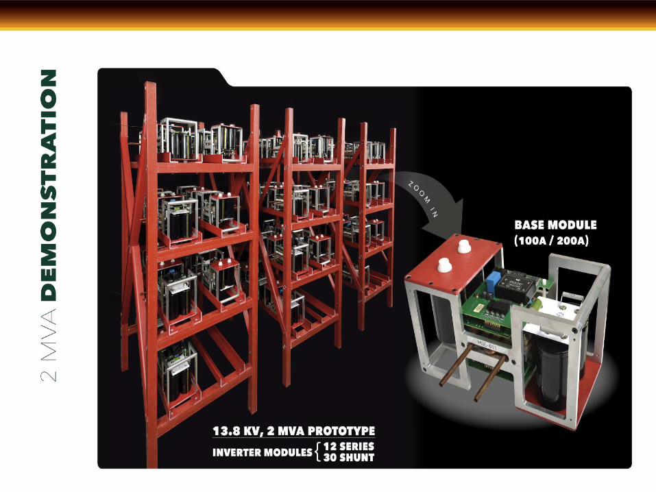
A working prototype of a 2-MVA transformer-less UPFC system
1
3rd Year Accomplishments
Q9: ► UPFC functionality test at low voltage level (4,160 V)
► System modulation, control and protection software developed
► 15-kV lab design, and construction
Q10: ► UPFC installation to the 15-kV high voltage lab
Q11: ► System for 13.8-kV/2 MVA UPFC demonstration configured
► Functional test with all shunt and series CMI sub-modules
Q12: ► Initial UPFC test results at 13.8-kV, independent P/Q control and
dc
voltage balancing control implemented
► Testing data collected and analyzed
Final Year
Accomplishments
2

3
Michigan UP Grid Scenario
Sankar, et. al, “ATC’S MACKINAC BACK-TO-BACK HVDC PROJECT:PLANNING AND OPERATION CONSIDERATIONS FOR
MICHIGAN’S EASTERN UPPER AND NORTHERN LOWER PENINSULAS”, CIGRE’ 2013 Grid of the future Symposium
• Loop flow problem: Power demand is high on south and east side of Lake Michigan.
But, some power finds its way through high impedance path in the UP.
• Eastern UP grid is “split” from that of West UP in order to prevent overloading of
lines/equipment and to eliminate under voltage. UP split is necessary for 95% time of
a year.
• Difficult to perform scheduled maintenance, to regulate voltage in eastern UP
• LP disconnected from UP due to high phase shifting requirement
4
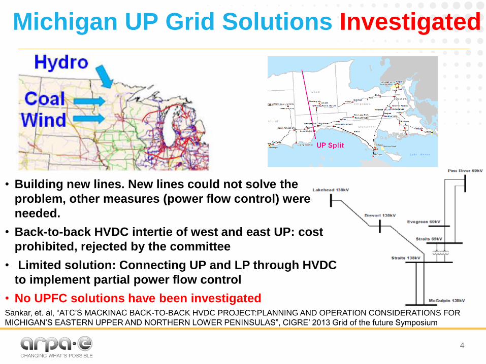
Michigan UP Grid Solutions Investigated
• Building new lines. New lines could not solve the
problem, other measures (power flow control) were
needed.
• Back-to-back HVDC intertie of west and east UP: cost
prohibited, rejected by the committee
• Limited solution: Connecting UP and LP through HVDC
to implement partial power flow control
• No UPFC solutions have been investigated Sankar, et. al, “ATC’S MACKINAC BACK-TO-BACK HVDC PROJECT:PLANNING AND OPERATION CONSIDERATIONS FOR
MICHIGAN’S EASTERN UPPER AND NORTHERN LOWER PENINSULAS”, CIGRE’ 2013 Grid of the future Symposium
5
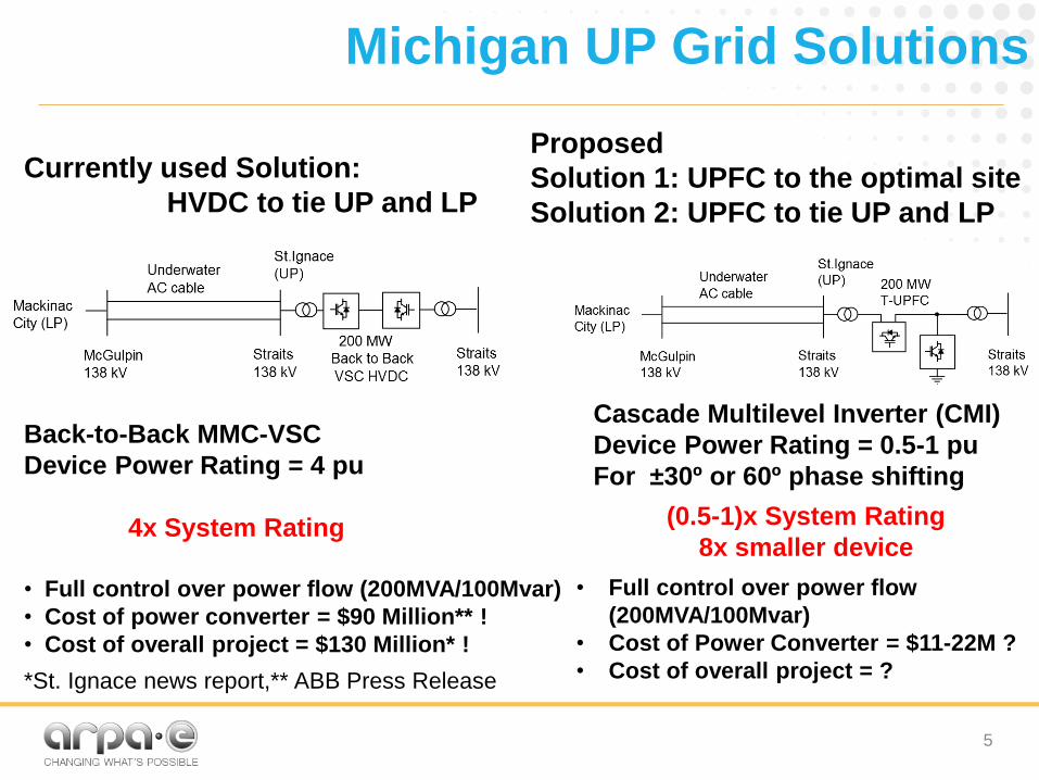
• Full control over power flow (200MVA/100Mvar)
• Cost of power converter = $90 Million** !
• Cost of overall project = $130 Million* !
*St. Ignace news report,** ABB Press Release
Back-to-Back MMC-VSC
Device Power Rating = 4 pu
4x System Rating
• Full control over power flow
(200MVA/100Mvar)
• Cost of Power Converter = $11-22M ?
• Cost of overall project = ?
Proposed
Solution 1: UPFC to the optimal site
Solution 2: UPFC to tie UP and LP
Currently used Solution:
HVDC to tie UP and LP
Cascade Multilevel Inverter (CMI)
Device Power Rating = 0.5-1 pu
For ±30º or 60º phase shifting
(0.5-1)x System Rating
8x smaller device
Michigan UP Grid Solutions

UPFC Test Results at 13.8 kV
7
Final Year
Accomplishments
LI
CI
PI
Sending End Receiving End
13.8 kV UPFC Test Setup and Experimental Waveforms
SeriesCMI
Sh
un
tC
MI
sV+ cV
cI
pI
MVS2-
+-
LXsX
LI
MVS1
0sV RV
Transformer-less
UPFC
13.8 0 kV 13.8 30 kV

UPFC Test Results at 13.8 kV
8
Final Year
Accomplishments
Power angle difference was reduced from the original 30° to 7°

UPFC Test Results at 13.8 kV
9
Final Year
Accomplishments
Power angle difference was reduced from the original 30° to 2°

Challenges and New Findings
New Findings:
DC capacitor energy of each CMI to increase network inertia.
Only a fraction of the system rating is needed for all UPFC functions.
Key Challenges Remaining:
Pilot test/ demonstration of the UPFC at 15-kV level and 2 MVA rating
System reliability, bypass and line fault protection
-1
-0.5
0
0.5
1
-0.2
-0.1
0
0.1
0.2
0
0.5
1
Original active power, P0(pu)Orignal reactive power, Q
0(pu)
|Ip| (p
u)
0
0.1
0.2
0.3
0.4
0.5
0.6
0.7
0.8
0.9
1
-1
-0.5
0
0.5
1
-0.2
-0.1
0
0.1
0.2
0
0.1
0.2
0.3
Original active power, P0(pu)Orignal reactive power, Q
0(pu)
|Vc| (p
u)
0
0.02
0.04
0.06
0.08
0.1
0.12
0.14
0.16
0.18
0.2
The maximum voltage,
Vc,max in the series CMIs
and the maximum current,
Ip,max in the shunt CMIs are
0.2 and 0.4 pu,
respectively.
Final Year
Accomplishments
10

Cost Benefit Studies
‣ On the IEEE 300 Bus system, the optimal
placements and parameters are:
Technology-to-Market
No. of
years Location
UPFC
(pu)
Invest
(M)
Benefit
(M)
1 121-119 0.138 $0.555 $11.14
5 191-225 1.595 $6.382 $79.91
10 191-225 1.595 $6.382 $166.2
Investme
nt Period Location
UPFC
(pu) Invest (M)
Benefit
(M)
1 191-225 1.5954 $6.382 $79.91
2 121-119 0.1187 $0.474 $66.63
3 242-245 0.0101 $0.04 $10.13
SUBSEQUENT INVESTMENT STUDY (5 YEAR BASE)
0 50 100 150 200 250 300 350 400
40
60
80
100
120
140
Operating range in MVAr
US
$/k
VA
r
Equipment cost
Transformerless UPFC
TCSC
SVC
STATCOM
Traditional UPFC
0 50 100 150 200 250 300 350 40050
70
90
110
130
150
170
190
Operating range in MVAr
US
$/k
VA
r
Investment cost
Transformerless UPFC
TCSC
SVC
STATCOM
Traditional UPFC
11

Near-term Plans
Key commercial challenges to date:
– Uncertain capital funding flow to sustain product development efforts
beyond ARPA-E.
– Strong inertia and risk-averse culture of power industry (i.e. utility
and vendors-alike).
– Securing real-world demonstration partners for technology.
Upcoming commercial activities:
– Currently talking to a couple of interested companies to explore a
pilot project.
– Talking to investors to set up a startup.
Technology-to-Market
12

Post ARPA-E Goals
Immediate Post-ARPA-E plan
– Upgrade of prototype to a product
– Validation of all protection functions to demonstrate reliability
– Technology transfer of the Transformer-less UPFC
– Demonstration of the Transformer-less UPFC technology
Resources to be expected
– Investors
– Utility companies
– Governmental agencies
13

Conclusions
A cost-effective power flow control device has been developed.
The new UPFC is modular, scalable, reliable, compact, lightweight, and highly efficient.
The new UPFC can control voltage, compensate impedance, and shift phase angle, which has been verified experimentally.
Large-scale test cases were used for study of:
- Cost saving through congestion reduction; - Hourly dispatch for power flow control; - Reduction of loop flows; - Increase of wind power injection.
14


