' <- I' c( TRANSIENT MODELING OF THE THERMOHYDRAULIC BEHAVIOR OF HIGH TEMPERATURE HEAT PIPES FOR SPACE REACTOR APPLICATIONS* Michael L.-Hall and Joseph M. Doster Nuclear Engineering Department North Carolina State University l e.. i ""? ' ABSTRACT Many proposed space reactor designs employ heat pipes as a means of convey- ing heat. Previous researchers have been concerned with steady state operation, but the transient operation is of interest in space reactor applications due to the necessity of remote startup and shutdown. A model is being developed to study the dynamic behavior of high temperature heat pipes during startup, shutdown and normal operation under space environments. Model development and preliminary re- sults for a hypothetical design of the system are presented. INTRODUCTION HEAT PIPE DESCRIPTION A heat pipe is an effective means of transferring heat from one location to another without pumps or moving parts. It consists of a closed system filled with a working fluid. One section of the pipe is placed in a heat source, causing the working fluid to evaporate and the resultant vapor to expand into the remainder of the heat pipe. A different section of the heat pipe is placed in a heat sink, causing the working fluid to condense. The liquid is then conveyed back to the evaporator ke.ct'ion by capillary action through a wick structure (see figure 1). The primary heat transfer is due to the latent heat of the working fluid, which results in a nearly isothermal system. The large heat transfer with the accomp- anying small change in temperature makes the heat pipe equivalent to a structure with a very high thermal conductivity. DESIGN CONSIDERATIONS FOR SPACE REACTOR USE Many of the current space based reactor designs for both civilian and mili- tary applications employ heat pipes as a means of conveying heat (ref. 1). In these designs, thermal radiation is the principal means for rejecting waste heat from the reactor system, making it desirable to operate at high temperatures. *The research was performed under appointment to the Nuclear Engineering, Health Physics, and Radioactive Waste Management Fellowships program administered by Oak Ridge Associated Universities for the U. S. Department of Energy. 313
Transcript
' < - I' c(
TRANSIENT MODELING OF THE THERMOHYDRAULIC BEHAVIOR OF HIGH TEMPERATURE HEAT PIPES
FOR SPACE REACTOR APPLICATIONS*
Michael L.-Hall and Joseph M. Doster Nuclear Engineering Department North Carolina State University
l
e.. i ""? '
ABSTRACT
Many proposed space r e a c t o r d e s i g n s employ h e a t p i p e s as a means of convey- i n g h e a t . Prev ious r e s e a r c h e r s have been concerned w i t h s t e a d y s t a t e o p e r a t i o n , bu t t h e t r a n s i e n t o p e r a t i o n i s of i n t e r e s t i n space r e a c t o r a p p l i c a t i o n s due t o t h e n e c e s s i t y of remote s t a r t u p and shutdown. A model i s be ing developed t o s t u d y t h e dynamic behavior of h i g h tempera ture h e a t p i p e s d u r i n g s t a r t u p , shutdown and normal o p e r a t i o n under space environments. Model development and p r e l i m i n a r y re- s u l t s f o r a h y p o t h e t i c a l des ign of t h e system are p r e s e n t e d .
INTRODUCTION
HEAT PIPE DESCRIPTION
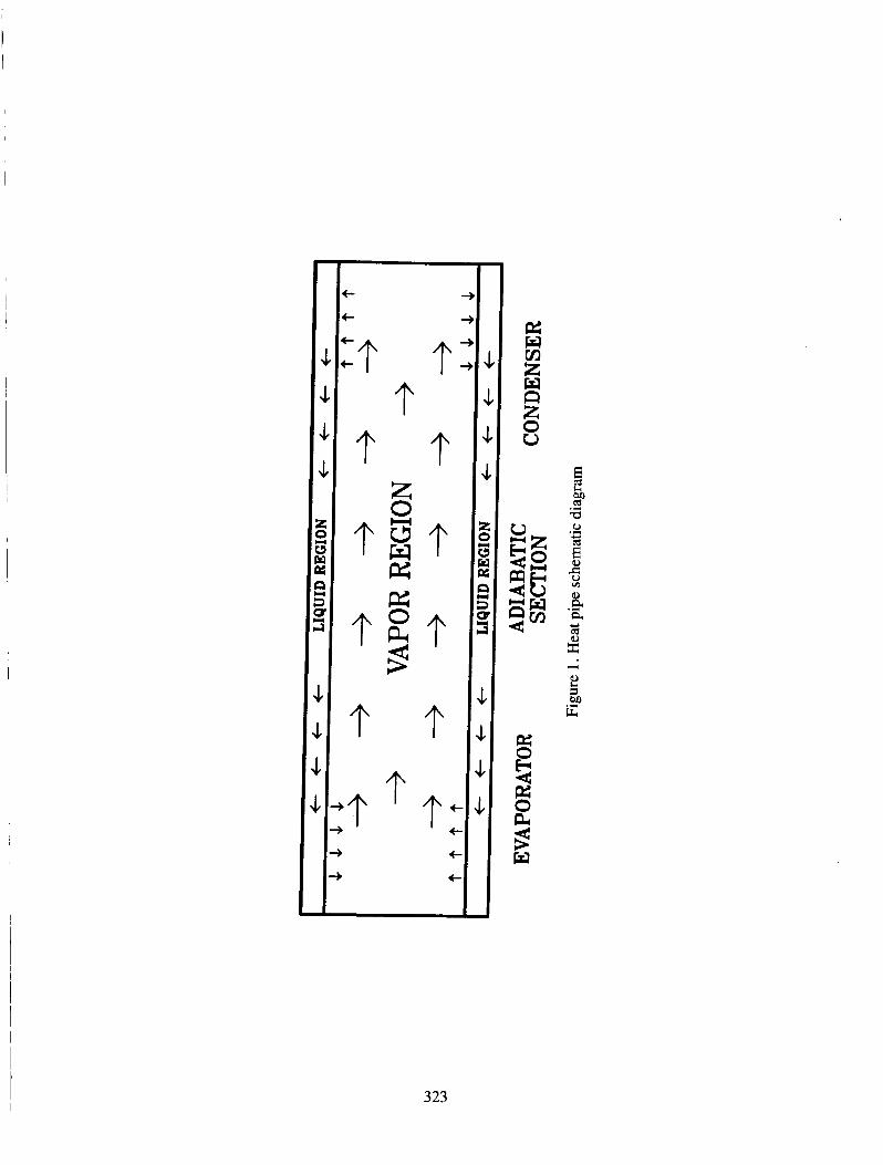
A h e a t p i p e i s an e f f e c t i v e means of t r a n s f e r r i n g h e a t from one l o c a t i o n t o a n o t h e r w i t h o u t pumps o r moving p a r t s . It c o n s i s t s of a c losed system f i l l e d w i t h a working f l u i d . One s e c t i o n of t h e p i p e is placed i n a h e a t s o u r c e , c a u s i n g t h e working f l u i d t o e v a p o r a t e and t h e r e s u l t a n t vapor t o expand i n t o t h e remainder of t h e h e a t pipe. A d i f f e r e n t s e c t i o n of t h e h e a t p ipe i s p laced i n a h e a t s i n k , c a u s i n g t h e working f l u i d t o condense. The l i q u i d i s then conveyed back t o t h e e v a p o r a t o r ke.ct'ion by c a p i l l a r y a c t i o n through a wick s t r u c t u r e ( s e e f i g u r e 1). The pr imary h e a t t r a n s f e r i s due t o t h e l a t e n t h e a t of t h e working f l u i d , which results in a nearly isothermal system. The large h e a t t r a n s f e r w i t h t h e accomp- anying s m a l l change i n tempera ture makes t h e h e a t p i p e e q u i v a l e n t t o a s t r u c t u r e w i t h a very h igh thermal c o n d u c t i v i t y .
D E S I G N CONSIDERATIONS FOR SPACE REACTOR USE
Many of t h e c u r r e n t space based r e a c t o r d e s i g n s f o r both c i v i l i a n and m i l i - t a r y a p p l i c a t i o n s employ h e a t p i p e s as a means of conveying h e a t ( r e f . 1). I n t h e s e d e s i g n s , thermal r a d i a t i o n i s t h e p r i n c i p a l means f o r r e j e c t i n g was te h e a t from t h e r e a c t o r system, making i t d e s i r a b l e t o o p e r a t e a t h i g h tempera tures .
*The r e s e a r c h w a s performed under appointment t o t h e Nuclear Engineer ing , Heal th P h y s i c s , and R a d i o a c t i v e Waste Management Fel lowships program a d m i n i s t e r e d by Oak Ridge Assoc ia ted U n i v e r s i t i e s f o r t h e U. S. Department of Energy.
313
Li th ium is g e n e r a l l y t h e working f l u i d of c h o i c e as i t undergoes a l i qu id -vapor t r a n s f o r m a t i o n a t t h e p r e f e r r e d o p e r a t i n g t empera tu re . There a re , however, prob- l e m s i n h e r e n t t o t h e c h o i c e of a l i q u i d metal as t h e working f l u i d . The r e a c t o r assembly w i l l have t o be launched i n t o o r b i t , presumably i n a c o l d s t a t e w i t h t h e l i t h i u m s o l i d . T h e r e f o r e , t h e c o n d i t i o n s under which t h e h e a t p i p e w i l l be s e l f - pr iming from a f r o z e n s t a t e are of g r e a t i n t e r e s t . A s imi l a r problem is t h a t of r e s t a r t i n g t h e h e a t p i p e a f t e r i t has been s h u t down and al lowed t o s o l i d i f y ; t h e d i f f e r e n c e between t h i s problem and t h e fo rmer one be ing t h e i n i t i a l d i s t r i b u t i o n of t h e s o l i d l i t h i u m . An a d d i t i o n a l conce rn , p a r t i c u l a r l y i n m i l i t a r y a p p l i c a - t i o n s , i s t h e a b i l i t y of t h e system t o hand le extreme b u r s t s of h e a t i n p u t con- c e n t r a t e d a t a p a r t i c u l a r l o c a t i o n such as might be expec ted i f t h e s a t e l l i t e were t h e s u b j e c t of a m i l i t a r y a t t a c k .
PURPOSE OF THIS WORK
The s t e a d y s t a t e behav io r of h e a t p i p e s h a s been s t u d i e d by o t h e r r e s e a r c h e r s ( r e f s . 2 , 3 , 4 ) . However, t h e n a t u r e of t h e p r e v i o u s l y mentioned p r o c e s s e s of re- mote s t a r t u p , res tar t , and r e a c t i o n t o t h r e a t s n e c e s s i t a t e s an a c c u r a t e , d e t a i l e d t r a n s i e n t model of t h e h e a t p i p e o p e r a t i o n . T h i s pape r cove r s t h e development of a model of t h e vapor c o r e r e g i o n of t h e h e a t p i p e which is p a r t of a larzer model of t h e e n t i r e h e a t p i p e the rma l r e sponse . Other t r a n s i e n t h e a t p i p e modeling has been done, i n c l u d i n g a the rma l model of a low t e m p e r a t u r e h e a t p i p e by Chang and Colwell ( r e f . 5 ) which does n o t i n c l u d e t h e h y d r a u l i c b e h a v i o r modeled i n t h i s pape r . Another n o t a b l e e f f o r t i n v o l v e s a m o d i f i c a t i o n of t h e ATHENA code t o model a n e n t i r e s p a c e r e a c t o r system ( r e f . 6 ) . T h i s pape r d i f f e r s from t h e ATHENA code m o d i f i c a t i o n i n i t s modeling of d i f f u s i o n , which t h e ATHENA code does n o t t rea t . I n a d d i t i o n , f u t u r e p l a n s f o r t h e model p r e s e n t e d i n t h i s pape r i n c l u d e t h e modeling of s t a r t u p from a f r o z e n s ta te .
MODEL DEVELOPMENT
CORE MODEL
The vapor c o r e i s modeled u s i n g t h e area averaged Navier-Stokes e q u a t i o n s i n one dimension, which t a k e i n t o account t h e e f f e c t s of mass, ene rgy and momentum t r a n s f e r . The c o r e model i s s i n g l e phase ( g a s e o u s ) , but c o n t a i n s two components: l i t h i u m gas and a noncondens ib l e vapor. The d i f f e r e n t i a l form of t h e e q u a t i o n se t used i s :
Mixture C o n t i n u i t v Equat ion
3 14
Noncondensi b l e C o n t i n u i t y Equation
Mixture I n t e r n a l Energy Equat ion
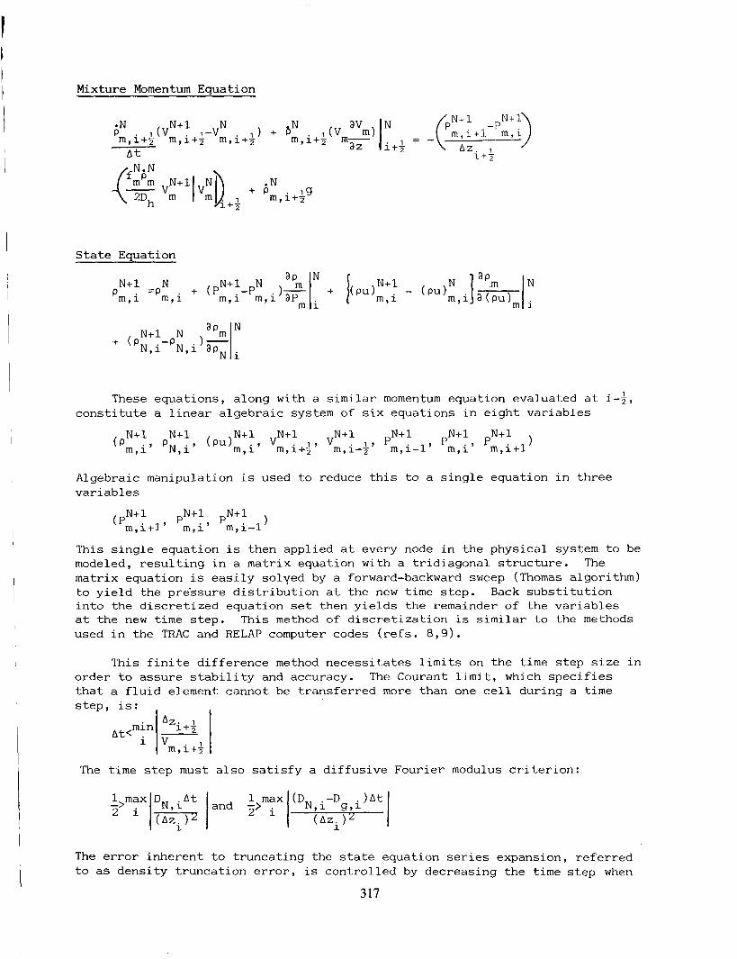
Mixture Momentum Eauat ion
S t a t e Equat ion
This e q u a t i o n set presupposes t h e thermal e q u i l i b r i u m of t h e l i t h i u m gas and t h e noncondens ib le , making a second i n t e r n a l energy e q u a t i o n unnecessary . The g a s e s are assumed t o have t h e same convect ive v e l o c i t y , e l i m i n a t i n g t h e need f o r a second momentum e q u a t i o n . However, d i f f e r i n g d i f f u s i v e v e l o c i t i e s are allowed w i t h t h e i n c l u s i o n of c o n c e n t r a t i o n d r i v e n mass d i f f u s i o n ( r e f . 7 ) . Evaporat ion and condensa t ion provide mass and energy t r a n s f e r t o and from t h e l i q u i d wick s e c t i o n . Condensation i s assumed t o occur only a t t h e l iqu id-vapor i n t e r f a c e , and no t by l i q u i d droplet format ion i n t h e vapor core . The e v a p o r a t i o n rate is g iven by t h e f o l l o w i n g r e l a t i o n :
Convect ive energy l o s s t o t h e wick s u r f a c e i s i n c l u d e d , but thermal conduct ion i s n o t inc luded i n t h e model a t p r e s e n t . The body f o r c e s are assumed z e r o f o r a s p a c e based system.
T h i s system of coupled n o n l i n e a r p a r t i a l d i f f e r e n t i a l e q u a t i o n s is s o l v e d u s i n g a f i n i t e d i f f e r e n c e method. F i r s t , t h e e q u a t i o n s are d i f f e r e n c e d s p a t i a l l y , u s i n g a s t a g g e r e d mesh i n which t h e f l u i d p r o p e r t i e s are e v a l u a t e d a t t h e ce l l c e n t e r s and v e l o c i t i e s are e v a l u a t e d a t c e l l boundaries . When i t is n e c e s s a r y t o e v a l u a t e a f l u i d p r o p e r t y a t a c e l l boundary, t h e v a r i a b l e i s "donored" (symbol- i z e d by a dot over t h e v a r i a b l e ) by s e t t i n g it e q u a l t o t h e closest "upstream" c e l l c e n t e r v a l u e , where "upstream" is determined by t h e v e l o c i t y at t h a t loca- t i o n . For exanplq , t h e donored d e n s i t y i s d e f i n e d as:
315
The e q u a t i o n s are d i f f e r e n c e d tempora l ly u s i n g a semi- impl ic i t d i s c r e t i z a t i o n which m a i n t a i n s a l i n e a r system i n t h e new time v a r i a b l e s whi le adding i n c r e a s e d s t a b i l i t y over a f u l l y e x p l i c i t method. c i t i e s i n t h e convec t ive terms and t h e p r e s s u r e s i n t h e momentum e q u a t i o n are e v a l u a t e d a t t h e new t i m e s t e p . F i n a l l y , t h e s t a t e e q u a t i o n is d i f f e r e n c e d s e p a r a t e l y by expanding i t about t h e p r e s e n t t i m e s t e p i n a T a y l o r ' s series, t r u n c a t i n g t h e series a f t e r t h e l inear terms and e v a l u a t i n g t h e t r u n c a t e d series a t t h e new t i m e s t e p . The f i n a l d i s c r e t i z e d system is:
I n t h e semi- impl ic i t method, t h e velo-
Mix t u re Con t i n u i t v Eauat i o n
Noncondensible C o n t i n u i t y Eauat ion
-; m N D I i-s (N 'N,i -ZN N,i-1 )I i-%
Mixture I n t e r n a l Energy Equat ion
A t Az Az: I
'N, i+l-'N, i N ( NLAz .) +rNhPc-H(;)(Tm,i-Tm,i) 2 N + K [ 1 b m ( D N h N - D g h g )Ii+% N
1 g i i+k N N - b m ( D N h -D h ) I . lcN,i-xN,i-l)]
N N g g 1-3 'Zi-2
316
Mixture Momen tum Equation
min At<
State Eauation
'Zi+2 - V m, i++
N+l - N N+1 N - Pm,i 'm,i + (pm,i-pm,i)F
N N+1 N + ('N,i-'N,i
These equations, along with a similar momentum equation evaluated at i-3, constitute a linear algebraic system of six equations in eight variables
Algebraic manipulation is used to reduce this to a single equation in three vari ab1 es
1 N+l pN+l pN+l (pm,i+l' m,i' m,i-1
This single equation is then applied at every node in the physical system to be modeled, resulting in a matrix equation with a tridiagonal structure. The matrix equation is easily solyed by a forward-backward sweep (Thomas algorithm) to yield the pre'ssure distribution at the new time step. Back substitution into the discretized equation set then yields the remainder of the variables at the new time step. This method of discretization is similar to the methods used in the TRAC and RELAP computer codes (refs. 8,9) .
1 max DN,i 1 max (D -D --> 1 At land 2> N,i g,i 2 i 1 ( A Z ~ ) ~ (Azilz
The error inherent to truncating the state equation series expansion, referred to as density truncation error, is controlled by decreasing the time step when
317
t h e e r r o r exceeds a u s e r s p e c i f i e d va lue :
' m , i
WALL/WICK MODEL
I n t h e c u r r e n t work, t h e w a l l and t h e wick of t h e h e a t p ipe are modeled s i m p l i s t i c a l l y . A d e t a i l e d thermohydraul ic model of t h e wick i s under develop- ment. The primary reasons f o r i n c l u d i n g a model of t h e w a l l and t h e wick are: t o provide a w a l l t empera ture f o r c a l c u l a t i n g e v a p o r a t i o n rates and c o n v e c t i v e h e a t l o s s e s f o r t h e c o r e model; and t o connect t h e c o r e model w i t h boundary con- d i t i o n s e x t e r i o r t o t h e h e a t pipe. C u r r e n t l y , t h e w a l l and t h e wick are modeled as a s i n g l e e n t i t y , u s i n g a lumped parameters approach which assumes a c o n s t a n t tempera ture throughout t h e w a l l and t h e wick a t any p a r t i c u l a r a x i a l node. The mechanisms of h e a t t r a n s f e r a v a i l a b l e t o t h e wal l /wick are: e x t e r i o r h e a t i n p u t , e x t e r i o r r a d i a t i v e h e a t l o s s , convect ion t o t h e c o r e gas and e v a p o r a t i o n a t t h e core-wick i n t e r f a c e . The h e a t balance
r q'.' - ,aT4 + H(Tm-Tw) - ( 7 ) r h = i n W f g
A f t e r t h e c o r e model is updated t o t h e
e q u a t i o n f o r t h e wal l /wick i s then:
m C dTw W P - - dt As
new t i m e s t e p , t h e w a l l t empera ture is up-dated by i m p l i c i t l y d i f f e r e n c i n g t h i s e q u a t i o n and s o l v i n g t h e r e s u l t a n t n o n l i n e a r e q u a t i o n f o r t h e w a l l t empera ture by a Newton-Raphson r o o t f i n d i n g tech- n i q u e a t every a x i a l l o c a t i o n . E x t e r i o r boundary c o n d i t i o n s vary a long t h e l e n g t h of t h e h e a t p ipe . I n t h e e v a p o r a t o r s e c t i o n , a t o t a l n e t h e a t f l u x i n t o t h e h e a t p i p e is s p e c i f i e d . I n t h e a d i a b a t i c s e c t i o n of t h e h e a t p i p e , a l l h e a t l o s s mechanisms are set t o zero. R a d i a t i o n is t h e only means of h e a t l o s s assumed i n t h e condensing end of t h e h e a t pipe.
RESULTS
MODEL CONDITIONS
The model has been a p p l i e d t o a 2.Om h e a t p ipe t h a t c o n s i s t s of an evapora- t o r s e c t i o n of zE[O,.3], an a d i a b a t i c s e c t i o n f o r zs [ .3 ,1 .5] , and a condenser s e c t i o n f o r z ~ [ 1 . 5 , 2 ] . These s e c t i o n s are used o n l y t o de te rmine which boundary c o n d i t i o n s t o apply : h e a t i n p u t , z e r o h e a t f l u x , o r h e a t o u t p u t . A s t a r t i n g tempera ture of 700K i s used. The h e a t p i p e i s o p e r a t e d a t 15kW throughput f o r 20s i n o r d e r t o h e a t i t up and then t h e power is dropped t o t h e d e s i r e d o p e r a t i n g c o n d i t i o n of 1.184kW. A h e a t p i p e of t h i s d e s i g n would normal ly o p e r a t e at 15kW and 1500K, but t h e h i g h e s t throughput t h e model w i l l a l l o w w i t h an o p e r a t i n g tempera ture of 1500K is 1.184kW i f t h e only means of h e a t l o s s i s r a d i a t i v e cool ing . I n i t i a l l y , t h e h e a t p i p e is f i l l e d w i t h a noncondensible gas ( a i r ) a t a p r e s s u r e of 250Pa.
318
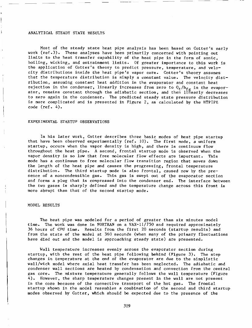
ANALYTICAL STEADY STATE RESULTS
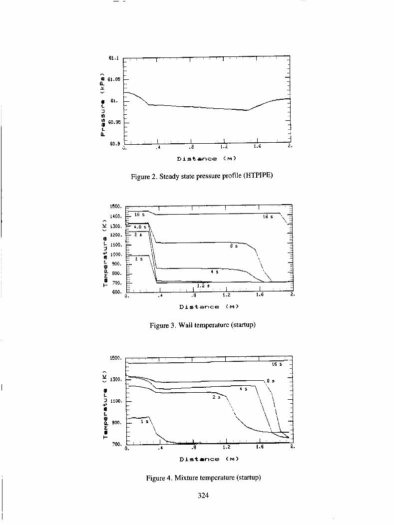
Most of the s teady s t a t e hea t pipe a n a l y s i s has been based on C o t t e r ' s e a r l y work ( r e f . 3 ) . These ana lyses have been p r imar i ly concerned wi th po in t ing out l i m i t s t o t h e hea t t r a n s f e r c a p a b i l i t y of the heat pipe i n t h e form of s o n i c , b o i l i n g , wicking, and entrainment l i m i t s . Of g r e a t e r importance t o t h i s work is t h e a p p l i c a t i o n of C o t t e r ' s theory t o p r e d i c t p re s su re , temperature , and velo- c i t y d i s t r i b u t i o n s i n s i d e the hea t p ipe ' s vapor core. C o t t e r ' s theory assumes t h a t t he temperature d i s t r i b u t i o n i s simply a cons tan t value. The v e l o c i t y d i s t - r i b u t i o n , assuming cons tan t hea t add i t ion i n the evapora tor and cons tan t hea t r e j e c t i o n i n t h e condenser, l i n e a r l y inc reases from zero t o Q /h i n the evapor- a t o r , remains cons tan t through the a d i a b a t i c s e c t i o n , and then l i n e a r l y decreases t o zero aga in i n the condenser. The predic ted s teady s t a t e p re s su re d i s t r i b u t i o n i s more complicated and i s presented i n Figure 2 , as c a l c u l a t e d by the HTPIPE code ( r e f . 4 ) .
t f g
EXPERIMENTAL STARTUP OBSERVATIONS
I n h i s l a t e r work, Co t t e r descr ibes th ree bas i c modes of hea t pipe s t a r t u p t h a t have been observed exper imenta l ly ( r e f . lo) . The f i r s t mode, a uniform s t a r t u p , occurs when the vapor dens i ty i s h igh , and t h e r e i s continuum flow throughout t h e hea t pipe. A second, f r o n t a l s t a r t u p mode i s observed when the vapor dens i ty i s so low t h a t f ree molecular f low e f f e c t s are important . This mode has a continuum t o f r e e molecular f low t r a n s i t i o n region t h a t moves down t h e length of the hea t pipe and causes the progress ing , f r o n t a l temperature d i s t r i b u t i o n . The t h i r d s t a r t u p mode is a l s o f r o n t a l , caused now by the pre- sence of a noncondensible gas. This gas is swept out of t he evapora tor s e c t i o n and forms a plug t h a t is compressed i n t o the condenser end. The i n t e r f a c e between t h e two gases i s sha rp ly def ined and the temperature change ac ross t h i s f r o n t is more abrupt than t h a t of the second s t a r t u p mode.
MODEL RESULTS
The hea t pipe was modeled f o r a period of g r e a t e r than s i x minutes model t i m e . The work was done i n FORTRAN on a VAX-11/750 and requi red approximately 36 hours of CPU t i m e . Resu l t s from t h e f i r s t 20 seconds ( s t a r t u p r e su l t s ) and from the s t a t e of t he model a t 360 seconds (when many of t h e primary f l u c t u a t i o n s have died out and t h e model i s approaching s teady s t a t e ) are presented.
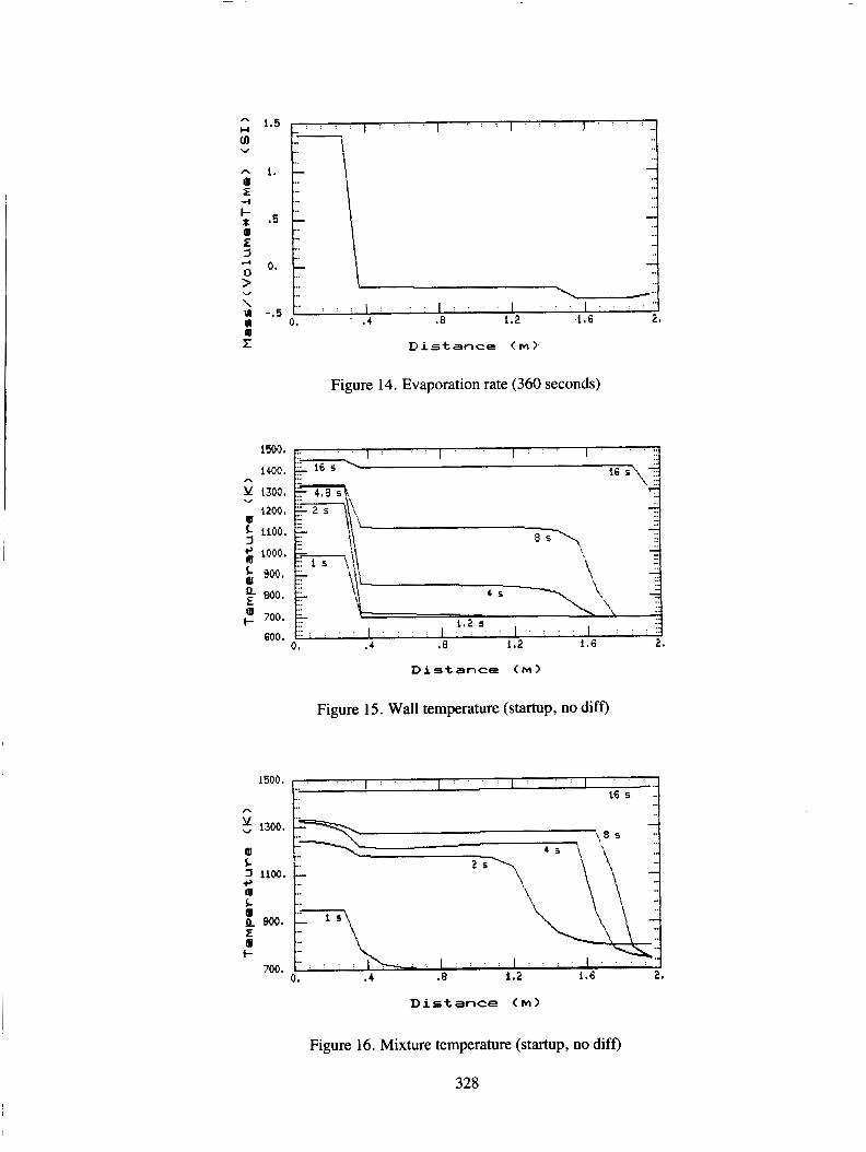
Wall temperature inc reases evenly across the evapora tor s e c t i o n dur ing s t a r t u p , with t h e rest of t h e hea t p ipe fol lowing behind (F igure 3 ) . The s t e p changes i n temperature a t t h e end of t h e evapora tor are due t o t h e s i m p l i s t i c wal l /wick model where a x i a l hea t t r a n s f e r has been neglected. The a d i a b a t i c and condenser w a l l s e c t i o n s are heated by condensation and convection from the c e n t r a l gas core . The mixture temperature gene ra l ly fol lows the w a l l temperature (F igure 4 ) . However, t h e sharp temperature changes present i n the w a l l are not p re sen t i n the core because of the convect ive t r a n s p o r t of t he hot gas. The f r o n t a l s t a r t u p shown i n the model resembles a combination of t he second and t h i r d s t a r t u p modes observed by C o t t e r , which should be expected due t o the presence of t he
319
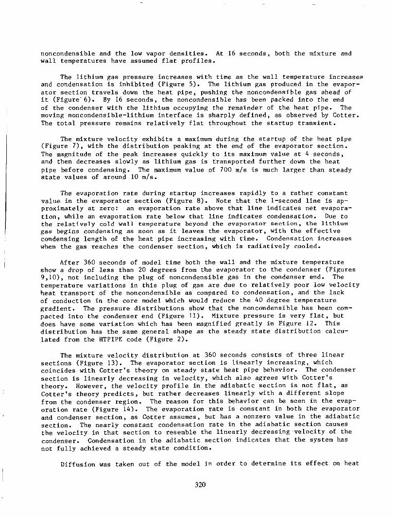
noncondensible and t h e low vapor d e n s i t i e s . A t 16 seconds , both t h e mixture and w a l l t empera tures have assumed f l a t p r o f i l e s .
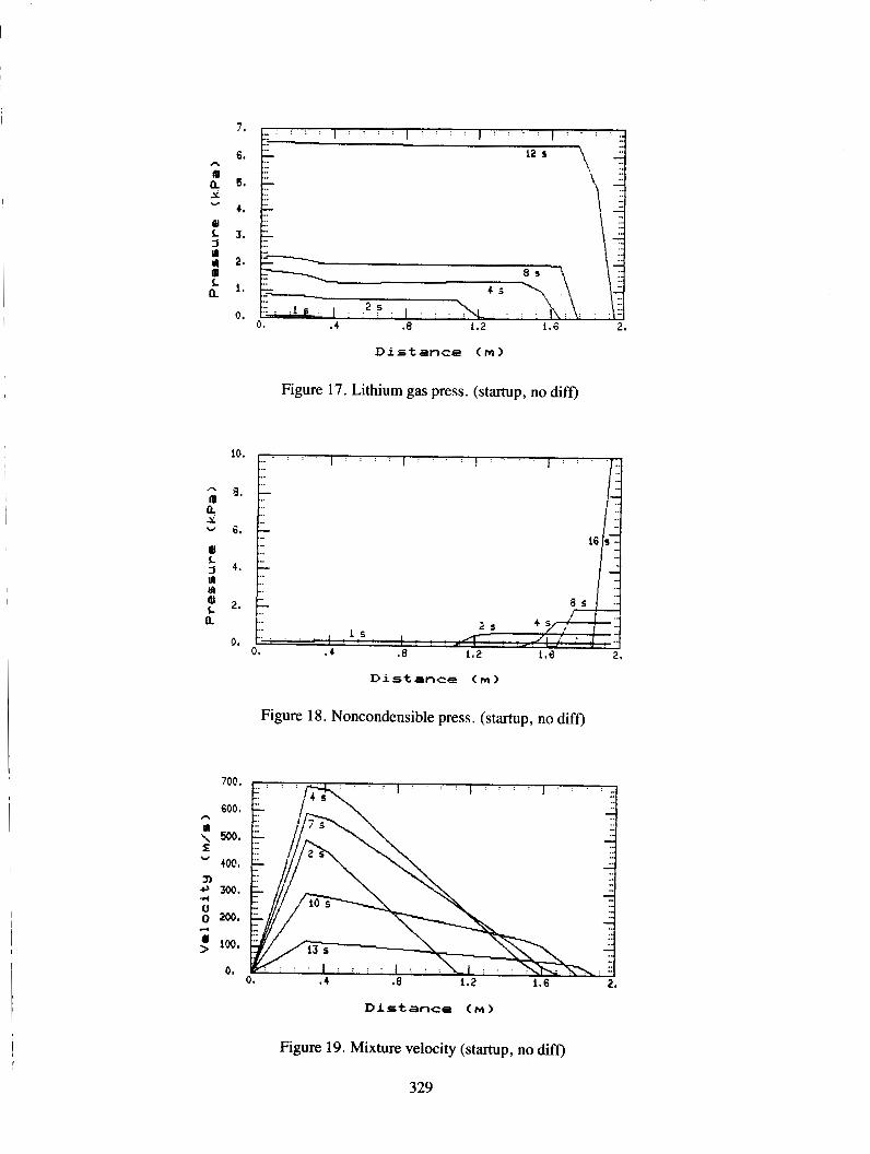
The l i t h i u m gas p r e s s u r e i n c r e a s e s w i t h t i m e as t h e w a l l t empera ture i n c r e a s e s and condensa t ion i s i n h i b i t e d ( F i g u r e 5 ) . The l i t h i u m gas produced i n t h e evapor- a t o r s e c t i o n t r a v e l s down t h e h e a t p i p e , pushing t h e noncondensible gas ahead of i t ( F i g u r e - 6 ) . By 16 seconds , t h e noncondensible has been packed i n t o t h e end of t h e condenser w i t h t h e l i t h i u m occupying t h e remainder of t h e h e a t pipe. The moving noncondens ib le - l i th ium i n t e r f a c e i s s h a r p l y d e f i n e d , as observed by C o t t e r . The t o t a l p r e s s u r e remains r e l a t i v e l y f l a t throughout t h e s t a r t u p t r a n s i e n t .
The mixture v e l o c i t y e x h i b i t s a maximum d u r i n g t h e s t a r t u p of t h e h e a t p ipe ( F i g u r e 7 ) , wi th t h e d i s t r i b u t i o n peaking a t t h e end of t h e e v a p o r a t o r s e c t i o n . The magnitude of t h e peak i n c r e a s e s q u i c k l y t o i t s maximum v a l u e a t 4 seconds , and then d e c r e a s e s s lowly as l i t h i u m gas is t r a n s p o r t e d f u r t h e r down t h e h e a t p i p e before condensing. The maximum v a l u e of 700 m / s is much l a r g e r than s t e a d y s t a t e v a l u e s of around 10 m / s .
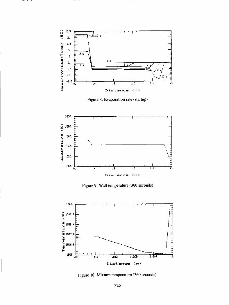
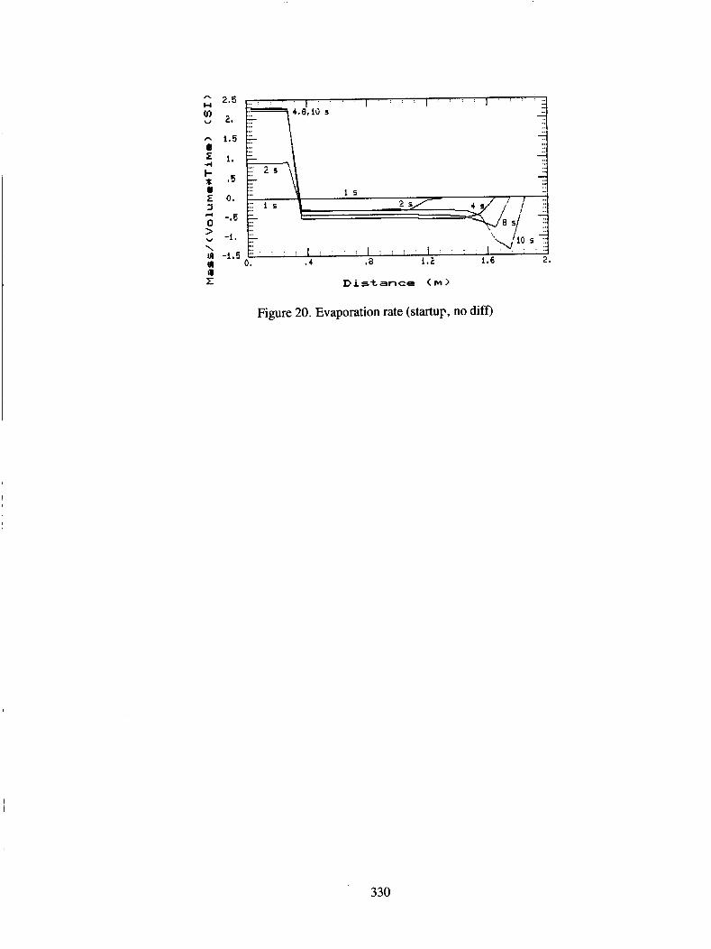
The e v a p o r a t i o n rate d u r i n g s t a r t u p i n c r e a s e s r a p i d l y t o a r a t h e r c o n s t a n t v a l u e i n t h e e v a p o r a t o r s e c t i o n ( F i g u r e 8). Note t h a t t h e l-second l i n e is ap- proximate ly a t z e r o : an e v a p o r a t i o n rate above t h a t l i n e i n d i c a t e s n e t evapora- t i o n , whi le an e v a p o r a t i o n rate below t h a t l i n e i n d i c a t e s condensat ion. Due t o t h e r e l a t i v e l y cold w a l l t e m p e r a t u r e beyond t he evaporator s e c t i o n , the l i t h i u m gas begins condensing as soon as it l e a v e s t h e e v a p o r a t o r , w i t h t h e e f f e c t i v e condensing l e n g t h of t h e h e a t p i p e i n c r e a s i n g w i t h t i m e . Condensat ion i n c r e a s e s when t h e gas reaches t h e condenser s e c t i o n , which i s r a d i a t i v e l y cooled.
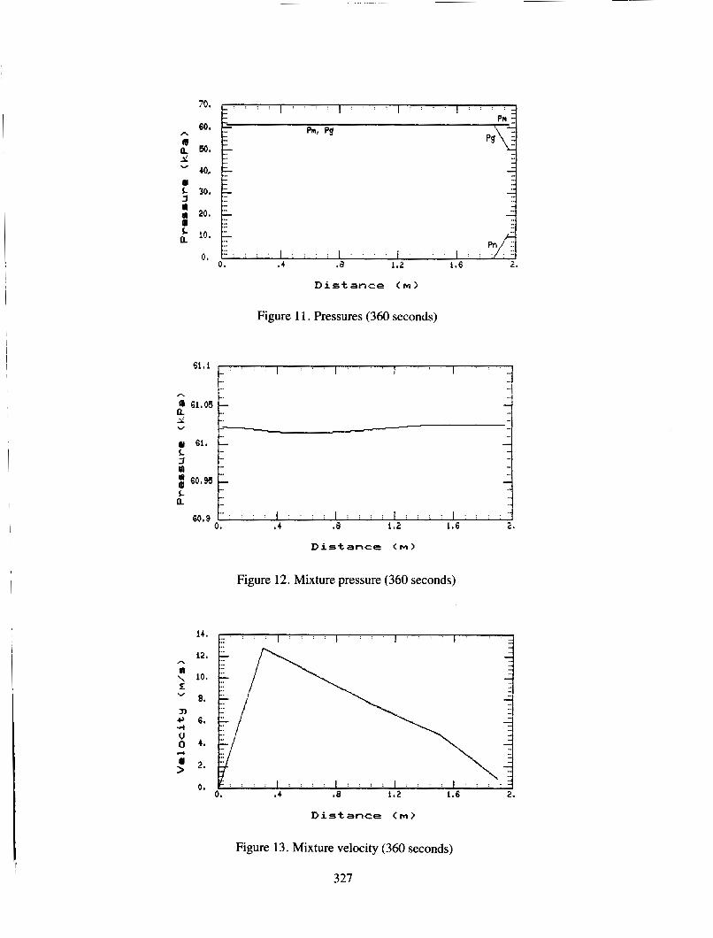
A f t e r 360 seconds of model t i m e both t h e w a l l and t h e mixture tempera ture show a drop of less than 20 d e g r e e s from t h e e v a p o r a t o r t o t h e condenser ( F i g u r e s 9,101, n o t i n c l u d i n g t h e p lug of noncondensible gas i n t h e condenser end. The tempera ture v a r i a t i o n s i n t h i s p lug of gas are due t o r e l a t i v e l y poor low v e l o c i t y h e a t t r a n s p o r t of t h e noncondensible as compared t o condensa t ion , and t h e l a c k of conduct ion i n t h e c o r e model which would reduce t h e 40 degree tempera ture g r a d i e n t . The p r e s s u r e d i s t r i b u t i o n s show t h a t t h e noncondens ib le has been com- p a c t e d i n t o t h e condenser end ( F i g u r e 11). Mixture p r e s s u r e i s very f l a t , but does have some v a r i a t i o n which has been magnif ied g r e a t l y i n F igure 12. This d i s t r i b u t i o n has t h e same g e n e r a l shape as t h e s t e a d y s ta te d i s t r i b u t i o n ca lcu- l a t e d from t h e HTPIPE code ( F i g u r e 2).
The mixture v e l o c i t y d i s t r i b u t i o n a t 360 seconds c o n s i s t s of t h r e e l i n e a r s e c t i o n s ( F i g u r e 13). The e v a p o r a t o r s e c t i o n i s l i n e a r l y i n c r e a s i n g , which c o i n c i d e s w i t h C o t t e r ' s t h e o r y on s t e a d y s t a t e h e a t p ipe behavior . The condenser s e c t i o n i s l i n e a r l y d e c r e a s i n g i n v e l o c i t y , which a l s o a g r e e s w i t h C o t t e r ' s theory . However, t h e v e l o c i t y p r o f i l e i n t h e a d i a b a t i c s e c t i o n i s n o t f l a t , as C o t t e r ' s t h e o r y p r e d i c t s , but r a t h e r d e c r e a s e s l i n e a r l y w i t h a d i f f e r e n t s l o p e from t h e condenser reg ion . The reason f o r t h i s behavior can be seen i n t h e evap- o r a t i o n ra te ( F i g u r e 14) . The e v a p o r a t i o n rate is c o n s t a n t i n both t h e e v a p o r a t o r and condenser s e c t i o n , as C o t t e r assumes, but has a nonzero v a l u e i n t h e a d i a b a t i c s e c t i o n . The n e a r l y c o n s t a n t condensa t ion rate i n t h e a d i a b a t i c s e c t i o n causes t h e v e l o c i t y i n t h a t s e c t i o n t o resemble t h e l i n e a r l y d e c r e a s i n g . v e l o c i t y of t h e condenser. Condensation i n t h e a d i a b a t i c s e c t i o n i n d i c a t e s t h a t t h e system has n o t f u l l y achieved a s t e a d y s t a t e c o n d i t i o n .
D i f f u s i o n w a s taken o u t of t h e model i n o r d e r t o de te rmine i t s e f f e c t on h e a t
pipe performance. F igures 15 through 20 ( i n which d i f f u s i o n has been neglec ted) correspond t o Figures 3 through 8. There i s l i t t l e d i f f e r e n c e between the sets of p l o t s , i n d i c a t i n g t h a t d i f f u s i o n does not a f f e c t t h e hea t p i p e performance dur ing t h i s t r a n s i e n t .
A t r a n s i e n t model of t he vapor core of high temperature hea t pipes has been developed. Model t r ends show good agreement with both a n a l y t i c a l s t eady s t a t e c a l c u l a t i o n s and exper imenta l ly observed s t a r t u p behavior. Di f fus ion does not have a l a r g e e f f e c t on hea t p ipe performance f o r t h i s p a r t i c u l a r t r a n s i e n t . In- v e s t i g a t i o n i n t o t h e t r a n s i e n t condi t ions during which d i f f u s i o n has a more pro- minent e f f e c t i s planned. Future modeling e f f o r t s w i l l i nc lude a thermohydraulic model of t he wick region wi th provis ions f o r s t a r t u p from a s o l i d s t a t e and con- duc t ion i n the vapor core .
SYMBOLS
As - s u r f a c e area of t h e l iquid-vapor i n t e r f a c e (m2) - s p e c i f i c hea t (J/kg*K) - mass d i f f u s i o n c o e f f i c i e n t (m2/s) D
Dh - h y d r a u l i c diameter (m) Emax - maximum t o l e r a b l e e r r o r f - f r i c t i o n f a c t o r g H h - entha lpy (J/kg)
hgc M - molecular weight (kg/kg*mole) m - mass (kg) P - pres su re ( P a )
Qt
q i n R - gas cons tan t (J/kg*mole'K) r - i n n e r wick r ad ius (m) T - temperature ( K ) t - t i m e ( s ) U - i n t e r n a l energy ( J /kg ) V - v e l o c i t y (m/s) X - mass f r a c t i o n z - a x i a l d i s t a n c e (m)
cP
- a c c e l e r a t i o n due t o g r a v i t y (m/s2) - hea t t r a n s f e r c o e f f i c i e n t ( J / m 2 O K )
- l a t e n t hea t of evapora t ion ( J /kg ) - entha lpy of t h e l i t h i u m gas upon changing phase ( J /kg )
h f g
- t o t a l hea t throughput (W) - hea t f l u x i n c i d e n t on the hea t pipe (W/m2)
Greek Letters:
r A - d i f f e r e n c e between two va lues , e.g. AXi=Xi+l/2 - X i - l / 2 , AXi+l/2=Xi+l-Xi € - e m i s s i v i t y P - d e n s i t y (kg/m3)
- evapora t ion r a t e (kg/m3 0s)
32 1
U - Stefan-Boltzmann c o n s t a n t ( J /m2*s*E4)
S u b s c r i p t s :
- l i t h i u m gas i - s p a t i a l node m - mixture N - noncondensible gas sa t - vapor-wick s a t u r a t i o n v a l u e W - wick/wal l
Supers c r i p t :
N - t i m e s t e p
REFERENCES
1.
2.
3.
4.
I
5.
6.
7.
8.
9.
10.
Jay E. Boudreau and David Buden, "A New Generat ion of Reac tors f o r Space Power," Symposium on Advanced Reac tor Systems , Washington, DC, 1982.
P. D. Dunn and D. A. Reay, Heat P ipes (Pergamon P r e s s , L t d - , Oxford, m, 1976).
T. P. C o t t e r , "Theory of Heat P i p e s , " LA-3246-MSY 1965.
F. C. Prenger , Jr., "Heat P ipe Computer Program (HTPIPE) User's Manual," LA-8101-M, 1979.
W. S. Chang and Gene T. Colwel l , "Mathematical Modeling of t h e T r a n s i e n t Opera t ing C h a r a c t e r i s t i c s of a Low-Tempeature Heat P i p e , " submi t ted t o Numerical Heat T r a n s f e r .
C. D. F l e t c h e r and H. Chow, "Simulat ion of t h e Genaral E lec t r ic SP-100 Space Reac tor Concept Using t h e ATHENA Computer Code," submi t ted t o t h e Thi rd Symposium on Space Nuclear Power Systems, January 1986.
R. B. B i r d , W. E. S t e w a r t , and E. N. L i g h t f o o t , T r a n s p o r t Phenomena (John Wiley and Sons , Inc. , New York, 1960).
-
--
"TRAC-PlA/MODl--An Advanced Best-Estimate Computer Program f o r P r e s s u r i z e d Water Reac tor Loss-of-Coolant Accident A n a l y s i s , " Los Alamos N a t i o n a l Labora tory r e p o r t .
V. H. Ransom, e t a l . , RELAP5/MOD2 - Code Manual, Volume 1: System Models L_ and S o l u t i o n Methods, EGG-SAAM-6377, A p r i l 1984.
- Code S t r u c t u r e ,
T. p. C o t t e r , "Heat P ipe S t a r t u p Dynamics ," Thermionic Conversion S p e c i a l i s t Conference, Pa lo A l t o , C A Y 1967.