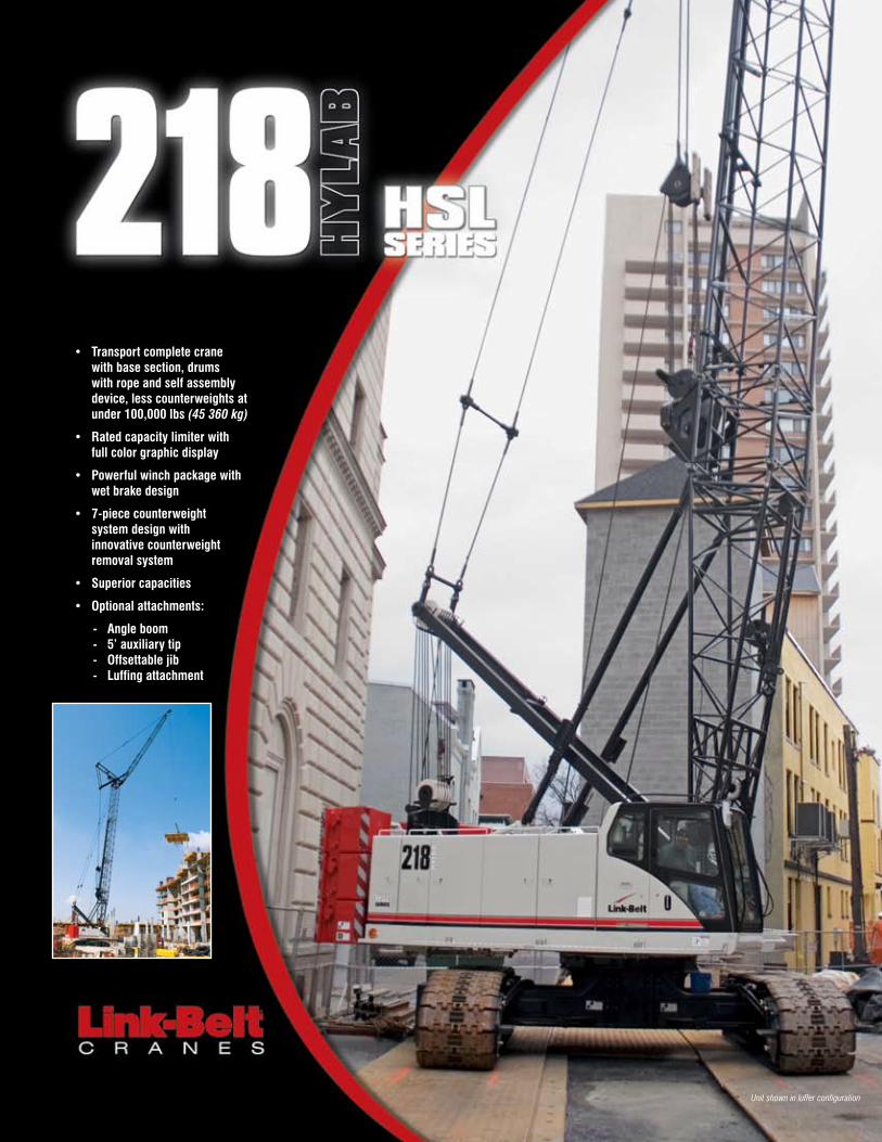
• Transport complete crane with base section, drums with rope and self assembly device, less counterweights at under 100,000 lbs (45 360 kg) • Rated capacity limiter with full color graphic display • Powerful winch package with wet brake design • 7-piece counterweight system design with innovative counterweight removal system • Superior capacities • Optional attachments: - Angle boom - 5’ auxiliary tip - Offsettable jib - Luffing attachment Unit shown in luffer configuration
Transcript
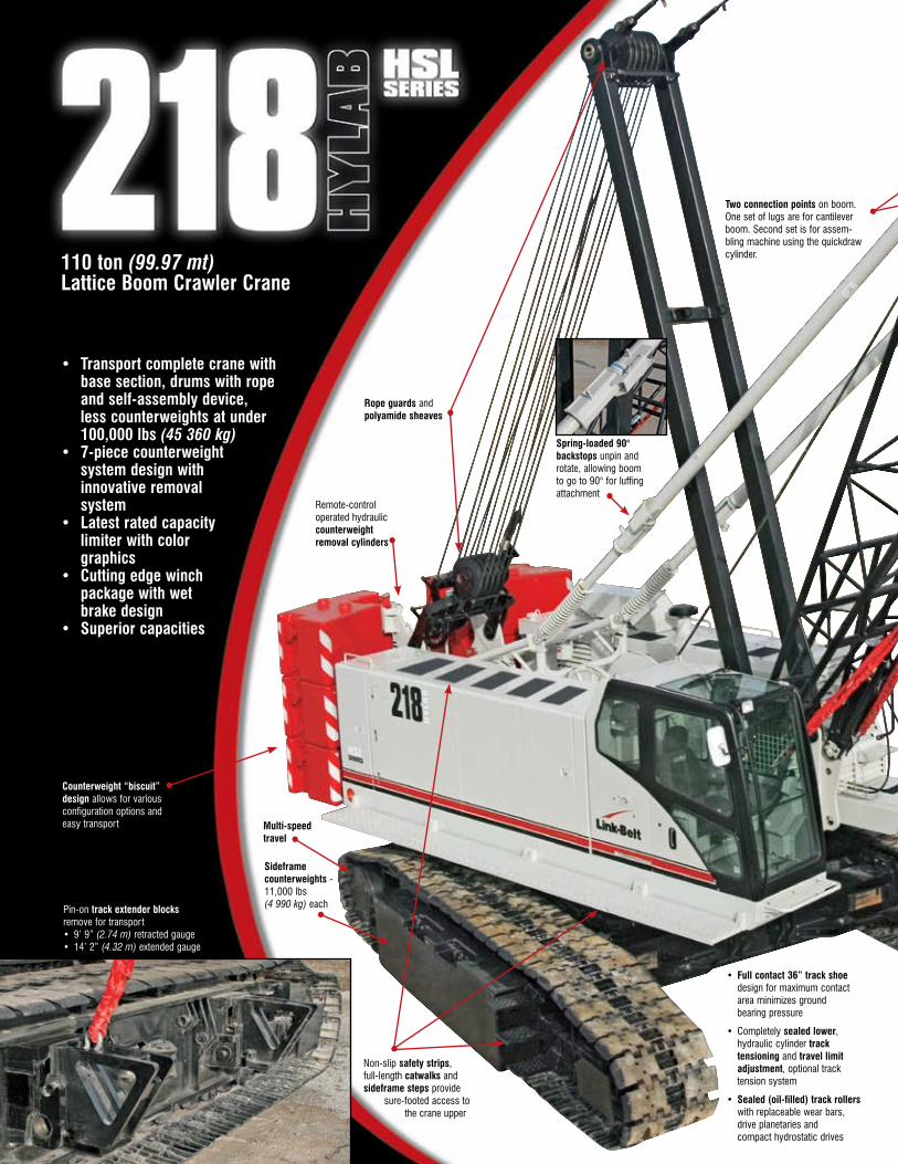
• Transport complete crane with base section, drums with rope and self assembly device, less counterweights at under 100,000 lbs (45 360 kg)
• Rated capacity limiter with full color graphic display
• Powerful winch package with wet brake design
• 7-piece counterweight system design with innovative counterweight removal system
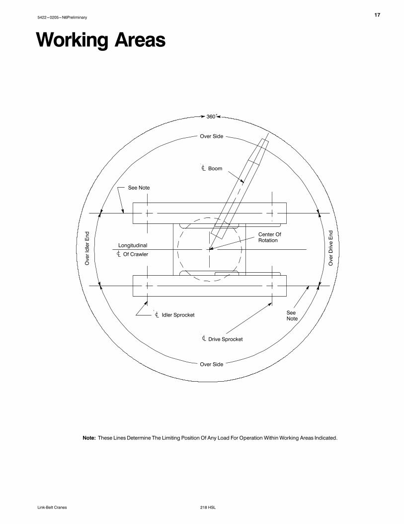
Non-slip safety strips, full-length catwalks and sideframe steps provide sure-footed access to the crane upper
Rope guards and polyamide sheaves
Two connection points on boom. One set of lugs are for cantilever boom. Second set is for assem-bling machine using the quickdraw cylinder.
Spring-loaded 90° backstops unpin and rotate, allowing boom to go to 90° for luffing attachment
Pin-on track extender blocks remove for transport• 9’ 9” (2.74 m) retracted gauge• 14’ 2” (4.32 m) extended gauge
• Full contact 36” track shoe design for maximum contact area minimizes ground bearing pressure
• Completely sealed lower, hydraulic cylinder track tensioning and travel limit adjustment, optional track tension system
• Sealed (oil-filled) track rollers with replaceable wear bars, drive planetaries and compact hydrostatic drives
Sideframe counterweights - 11,000 lbs (4 990 kg) each
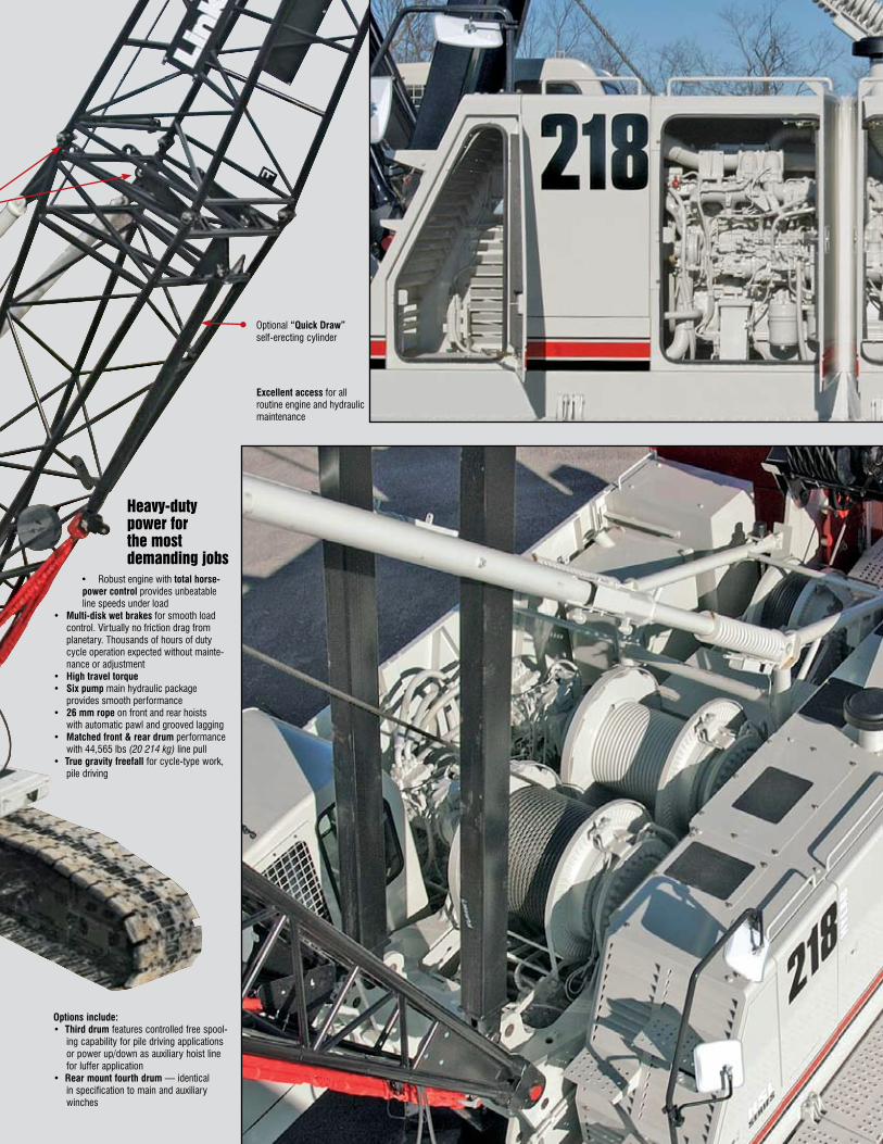
Heavy-duty powerfor themost demandingjobs
• Robust engine with total horse-power control provides unbeatable line speeds under load
• Multi-disk wet brakes for smooth load control. Virtually no friction drag from planetary. Thousands of hours of duty cycle operation expected without mainte-nance or adjustment
• High travel torque• Six pump main hydraulic package
provides smooth performance• 26 mm rope on front and rear hoists
with automatic pawl and grooved lagging• Matched front & rear drum performance
with 44,565 lbs (20 214 kg) line pull• True gravity freefall for cycle-type work,
pile driving
Options include:• Third drum features controlled free spool-
ing capability for pile driving applications or power up/down as auxiliary hoist line for luffer application
• Rear mount fourth drum — identical in specification to main and auxiliary winches
Excellent access for all routine engine and hydraulic maintenance
Optional “Quick Draw” self-erecting cylinder
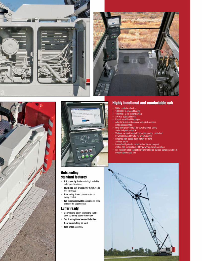
Outstandingstandardfeatures• HSL capacity limiter with high visibility
color graphic display
• Multi-disc wet brakes offer automatic or free fall mode
• Dual swing drives provide smooth swing control
• Full length removable catwalks on both sides of the upper house
Lufferready!• Conventional boom extensions can be
used as luffing boom extensions
• 3rd drum optional second hoist line
• Rear drum luffing jib hoist
• Fold-under assembly
Highlyfunctionalandcomfortablecab• Wide, uncluttered entry• 18,000 BTU air-conditioning• 19,000 BTU hot water heating• Six-way adjustable seat• Easy-to-read backlit gauges• Adjustable armrest console with pilot-operated
single-axis controls• Hydraulic pilot controls for variable hoist, swing
and travel performance• Variable hydraulic output from main pumps controlled
by variable hand throttle for infinite control• Fingertip high speed hoist button for front
and rear drum • Low-effort hydraulic pedals with minimal range of
motion can remain latched for power up/down operation• Full function rated capacity limiter monitored by load sensing via boom
hoist mounted load cell
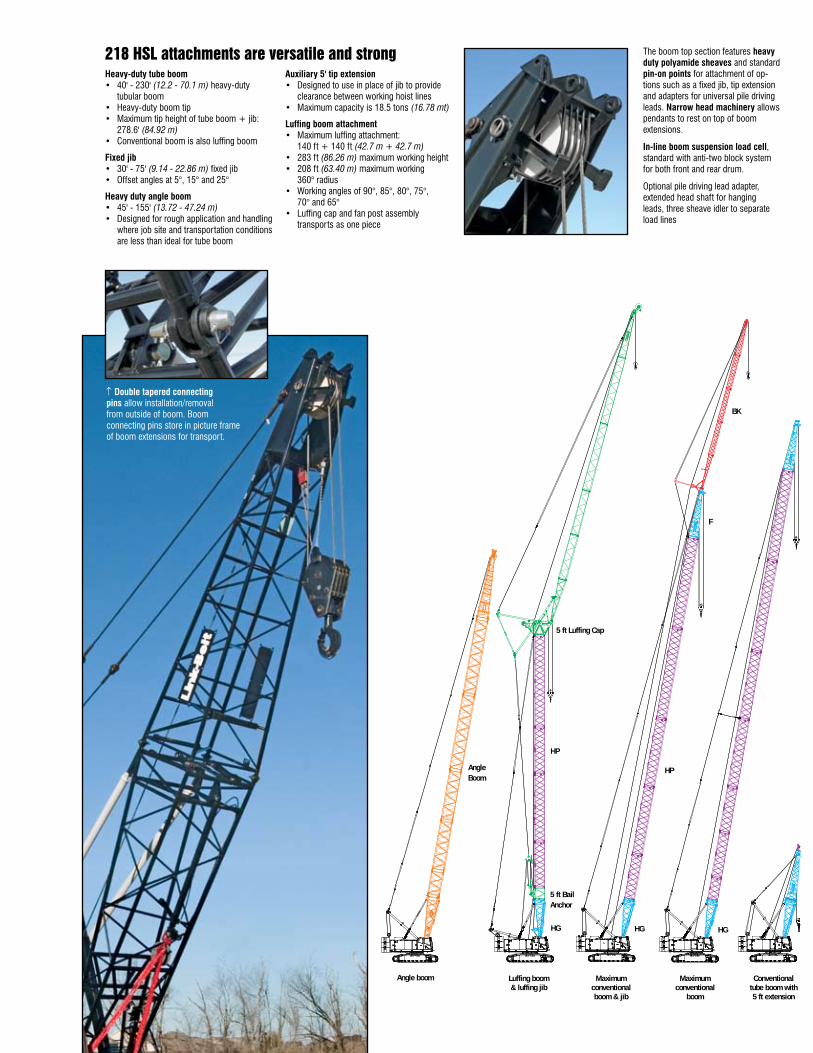
The boom top section features heavy duty polyamide sheaves and standard pin-on points for attachment of op-tions such as a fixed jib, tip extension and adapters for universal pile driving leads. Narrow head machinery allows pendants to rest on top of boom extensions.
In-line boom suspension load cell, standard with anti-two block system for both front and rear drum.
Optional pile driving lead adapter, extended head shaft for hanging leads, three sheave idler to separate load lines
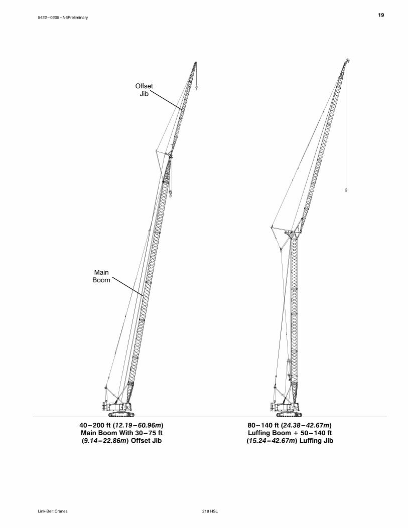
tubular boom• Heavy-duty boom tip• Maximum tip height of tube boom + jib:
278.6' (84.92 m)• Conventional boom is also luffing boom
Fixed jib• 30' - 75' (9.14 - 22.86 m) fixed jib• Offset angles at 5°, 15° and 25°
Heavy duty angle boom• 45' - 155' (13.72 - 47.24 m)• Designed for rough application and handling
where job site and transportation conditions are less than ideal for tube boom
Auxiliary 5' tip extension• Designed to use in place of jib to provide
clearance between working hoist lines• Maximum capacity is 18.5 tons (16.78 mt)
Luffing boom attachment• Maximum luffing attachment:
140 ft + 140 ft (42.7 m + 42.7 m)• 283 ft (86.26 m) maximum working height• 208 ft (63.40 m) maximum working
360° radius• Working angles of 90°, 85°, 80°, 75°,
70° and 65°• Luffing cap and fan post assembly
transports as one piece
↑ Double tapered connecting pins allow installation/removal from outside of boom. Boom connecting pins store in picture frame of boom extensions for transport.
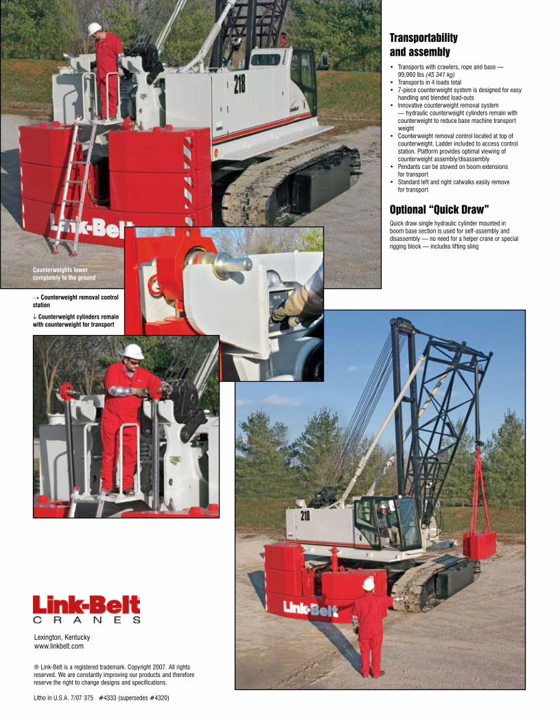
Transportabilityandassembly• Transports with crawlers, rope and base —
99,960 lbs (45 341 kg)• Transports in 4 loads total• 7-piece counterweight system is designed for easy
handling and blended load-outs• Innovative counterweight removal system
— hydraulic counterweight cylinders remain with counterweight to reduce base machine transport weight
• Counterweight removal control located at top of counterweight. Ladder included to access control station. Platform provides optimal viewing of counterweight assembly/disassembly
• Pendants can be stowed on boom extensions for transport
• Standard left and right catwalks easily remove for transport
Optional“QuickDraw”Quick draw single hydraulic cylinder mounted in boom base section is used for self-assembly and disassembly — no need for a helper crane or special rigging block — includes lifting sling
Counterweights lower completely to the ground
Lexington, Kentuckywww.linkbelt.com
® Link-Belt is a registered trademark. Copyright 2007. All rights reserved. We are constantly improving our products and therefore reserve the right to change designs and specifications.
Litho in U.S.A. 7/07 375 #4333 (supersedes #4320)
→ Counterweight removal control station
↓ Counterweight cylinders remain with counterweight for transport
15422---0205---N6Preliminary
218 HSLLink-Belt Cranes
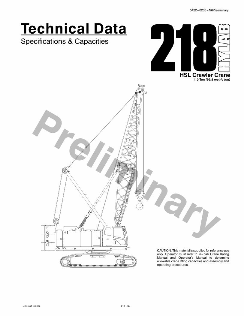
Technical DataSpecifications & Capacities
HSL Crawler Crane110 Ton (99.8 metric ton)
CAUTION: Thismaterial is supplied for referenceuseonly. Operator must refer to in---cab Crane RatingManual and Operator’s Manual to determineallowable crane lifting capacities and assembly andoperating procedures.
Fuel TankEquipped with fuel sight level gauges,flame arrester, and self ---closing cap withlocking eye for padlock.
Hydraulic System
Hydraulic PumpsThe pump arrangement is designed toprovide hydraulically powered functionsallowing positive, precise control with in-dependent or simultaneous operation ofall crane functions.S Two variable displacement pumpsoperating at 4,550 psi (319kg/cm2) and74 gal/min (280L/min) powers loadhoist drums, boomhoist drum, optionalthird drum, optional fourth drum, andtravel.
S One variable displacement pumpoperating at 4,623 psi (325kg/cm2) and42.3 gal/min (160L/min) powers theswing motors.
S One fixed displacement gear typepump operating at 2,985 psi(210kg/cm2) and15.9gal/min (60L/min)powers the lower jacks, counterweightremoval, quickdraw, side frame retract,and hoist brake cooling.
S One fixed displacement gear typepump operating at 1,422 psi(100kg/cm2) and 10.8 gal/min (41L/min)powers the pilot control system,clutches, brakes, and pump controls.
S One fixed displacement gear typepump operating at 1,420 psi(100kg/cm2) and 8.4 gal/min (32L/min)powers the optional tagline winch.
Hydraulic Reservoir119 gal (450L), equipped with sight levelgauge. Diffusers built in for deaeriation.
FiltrationTenmicron, full flow, line filter in thecontrolcircuit. All oil is filteredprior toentering thereservoir.
Counterbalance ValvesAll hoist motors are equipped with coun-terbalance valves to provide positive loadlowering and prevent accidental loaddrop if the hydraulic pressure is suddenlylost.
Load Hoist Drums
Each drum contains an axial piston, vari-able speed hydraulic motor with individu-al automatic winch motor brakes. Powerflow is directed through a patented,semi---outboard mounted, “wet” stylemulti ---disc brake. The brake is mountedon the “output” side of the planetary,which greatly reduces drag associatedwith most “wet” style brakes in free--- fallmode.S Power up/down & free--- fall operationmodes
S Automatic brakemode (spring applied,hydraulically released, wet type brake)
S Drum lagging grooved for wire ropeS Drum pawl controlled manuallyS Electronic drum rotation indicatorsS Mounted on anti --- friction bearingsS 21.81 in (0.55m) root diameterS 37.81 in (0.96m) flange diameterS 25.25 in (0.64m) widthThe free--- fall operationmode is designedto prevent load lowering even if the free---fall switch is accidentally activated.The automatic brake mode meets allOSHA requirements for personnel han-dling.
Optional Front---MountedThird Hoist Drum
The hydraulic winch is pinned to the frontof theupper frameand isused in conjunc-tion with a fleeting sheave and 3---sheaveidler assembly to run the wire rope overthe boom top section.S Power up/down for luffer applicationswhere a second load line is needed
S Controlled free spooling capability forpile driving applications or auxiliaryhoist line for luffer applications.
S 12.75 in (0.32m) root diameterS 22.75 in (0.58m) flange diameterS 17 in (0.43m) widthS Mounted on anti --- friction bearingsS 0.75 in (19mm) grooved lagging
2 5422---0205---N6Preliminary
218 HSL Link-Belt Cranes
Optional Rear---MountedFourth Hoist Drum
Drum contains an axial piston, variablespeed hydraulic motor with individual au-tomatic winch motor brakes. Power flowisdirected throughapatented, semi---out-board mounted, “wet” style multi ---discbrake.S Power up/down & free--- fall operationmodes
S Automatic brakemode (spring applied,hydraulically released, wet type brake)
S Drum lagging grooved for wire ropeS Drum pawl controlled manuallyS Electronic drum rotation indicatorsS Mounted on anti --- friction bearingsS 21.50 in (0.54m) root diameterS 40.94 in (1.04m) flange diameterS 24.63 in (0.62m) widthS Pins to rear of upper frameS Plumbing and valving standard withmain unit
The free--- fall operationmode is designedto prevent load lowering even if the free---fall switch is accidentally activated.The automatic brake mode meets allOSHA requirements for personnel han-dling.
Boom Hoist DrumContains a pilot controlled, bi---directional,axial piston motor and a planetary gear re-duction unit to provide positive control un-der all load conditions.S Spring applied, hydraulically released,disc type brake controlled automatically
S 0.78 in (20mm) grooved laggingS Drum pawl controlled automaticallyS Mounted on anti --- friction bearingsS 18.35 in (0.47m) root diameterS 30.40 in (0.77m) flange diameterS 11.16 in (0.28m) width
Swing System
Pilot controlled bi---directional axial pistonmotors andplanetary gear reductionunitsto provide positive control under all loadconditions.S Spring applied, hydraulically released,360˚ multi ---plate brake
S Free swing mode when lever is in neu-tral position
S Four position positive house lockS Two---speed swingS Audio/Visual swing alarmS Maximum swing speed is 2.5 rpm
Counterweight
Consists of a four---piece design that canbe easily lowered to the ground using theremoval cylinders.S “A” upper counterweight consists ofone, 25,260 lb (11 458kg) base slab
S Two side frame counterweights ---11,100 lb (5 035kg) each
Total combined counterweight, :ABC:plus side frame counterweights is85,020 lb (38 564kg).
Operator Cab
Fully enclosed modular steel compart-ment is independently mounted andpadded to protect against vibration andnoise.S All tinted/tempered safety glassS Folding hinge entry door and slidingfront glass window
S 19,000 BTU hot water heaterS 18,600 BTU air conditionerS Door and window locksS Circulating fanS Sun visorS Cloth seatS DefrosterS Windshield wipers and washerS Dry chemical fire extinguisherS Engine instrumentation panel (voltmeter,engine oil pressure, engine water tem-perature, fuel level, hydraulic oil tem-perature, hourmeter, and servicemoni-tor system)
S Electronic drum rotation indicators forfront and rear hoist drums
S Six way adjustable seatS Hand and foot throttleS Fully adjustable single axis controlsS Swing lever with swing brake and hornlocated on handle
S Bubble type levelS Ergonomic gauge layoutS Controls shut off leverS Control stand is adjustable for operatorcomfort.
Rated Capacity LimiterSystem
The HSL rated capacity limiter system is aboom hoist load cell system. This systemprovides the operator with useful geometri-cal data, to include:S Main Boom LengthS Main Boom AngleS Jib LengthS Jib AngleS Operating ModeS Load RadiusS Boom Tip HeightS Audible AlarmS Pre---Warning LightS Overload LightS Load On HookS Function kick---outs including over loadS Operator settable stops (rampedstops)S Anti ---Two Block IndicatorS Boom hoist dead end load cell (nolineriders)
Boom Hoist System
Designed to lift off maximum boom ormaximum boom plus jib unassisted. Op-erates up to a maximum boom angle of80˚ for conventional boomand90˚ for luf-fing boom. Boom hoist limit system limitsmaximum boom angle operation.S Pin---on bail frameS 12---part reeving with 20mm (0.787 in)wire rope
S 22 ft (6.71m) live mastS Two 1.25 in (32mm) pendantsS Tubular boom backstops (telescopictype)
S Sheaves contain sealed anti --- frictionbearings
S Boom speed from 10˚ ---70˚ is 69 sec-onds with no load. Speed was deter-mined using 100 ft (30.48m) of tubeboom.
Machinery Cab
Hinged doors (four on right side, three onleft side) for machinery access. Storage/rigging box located on operator’s side ofupper house. Equipped with rooftop ac-cess ladder and skid resistant finish onroof.
Catwalks
Standardon right and left sides. Catwalksare removable for reduced travel width.
35422---0205---N6Preliminary
218 HSLLink-Belt Cranes
Lower StructureCarbody
Lower FrameAll welded high strength steel [65,000 psi(448.16MPa) yield] box constructionframe with precision machined surfacesfor turntable bearing and rotating joint.S 9 ft 11 in (3.02m) overall widthS 11 ft 11 in (3.60m) overall length
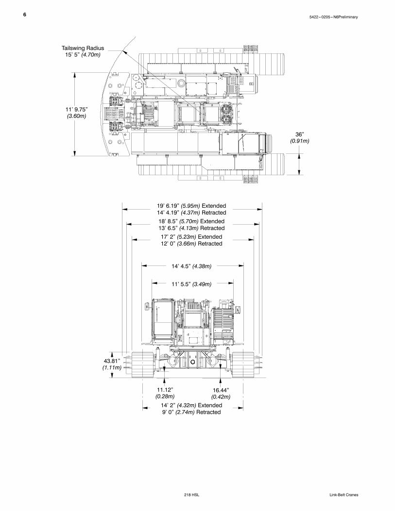
Side Frames
Side FramesAll welded, precision machined, steelframescanbehydraulically extendedandretracted by ahydraulic cylindermountedin the lower frame.S 14 ft 2 in (4.32m) extended gaugeS 9 ft (2.74m) retracted gaugeS 20 ft 6 in (6.25m) overall lengthS 36 in (0.90m) wide track shoesS Sealed (oil filled) drive planetariesS Compact travel drivesS Automatic hydraulic track adjustmentsystem --- optional
Track RollersS Ten sealed (oil filled) track rollers perside frame
S Heat treated,mountedonoil filledanti ---friction bearings
TracksHeat treated, self ---cleaning, multiplehinged track shoes joined by one---piecefull floating pins; 53 shoes per side frame
Take Up IdlersCast steel, heat treated, self ---cleaning,mounted on aluminum/bronze bushings.Lubricated through idler shaft.S Track Tension Adjustment --- Idlerwheel adjusted by means of hydrauliccylinder and hand pump. Idler wheelshaft held in position with shims afteradjustment is made.
Travel and Steering
Travel and SteeringEach side frame contains a pilot con-trolled, bi ---directional, axial piston motorandaplanetary gear reductionunit topro-vide positive control under all load condi-tions.S Individual control provides smooth,precise maneuverability including fullcounter---rotation.
S Spring applied, hydraulically releaseddisc type brake controlled automatically
S Maximum travel speed is 1.2 mph(1.93km/h).
S Designed to 30% gradeability
Optional --- Jack System
System contains four hydraulic cylindersindividually pinned on swing out beams.S Individual controls aremounted on car-body.
S Minimum height of carbody when rest-ing on pontoons is 16 in (0.41m).
S Maximum height of carbody when rest-ing on pontoons is 42 in (1.07m).
Attachment and OptionsConventional Tubular Boom40--230 ft (12.19---70.10m)
Basic Boom40 ft (12.19m) two---piece design thatutilizes a 20 ft (6.10m) base section anda 20 ft (6.10m) open throat top sectionwith in --- line connecting pins on 60 in(1.52m) wide and 50 in (1.27m) deepcenters.S Boom foot on 55.12 in (1.40m) centersS 3 in (7.62cm) diameter chordsS Lugs on base section for self assemblyS Self assembly cylinderS Deflector roller on top sectionS Permanent skid pads mounted on topsection to protect head machinery
S Four, 21.53 in, (54.69cm) root diameterpolymide sheaves mounted on sealedanti --- friction bearings
S Tip extension and jib connecting lugson top section
S Mechanical boom angle indicator
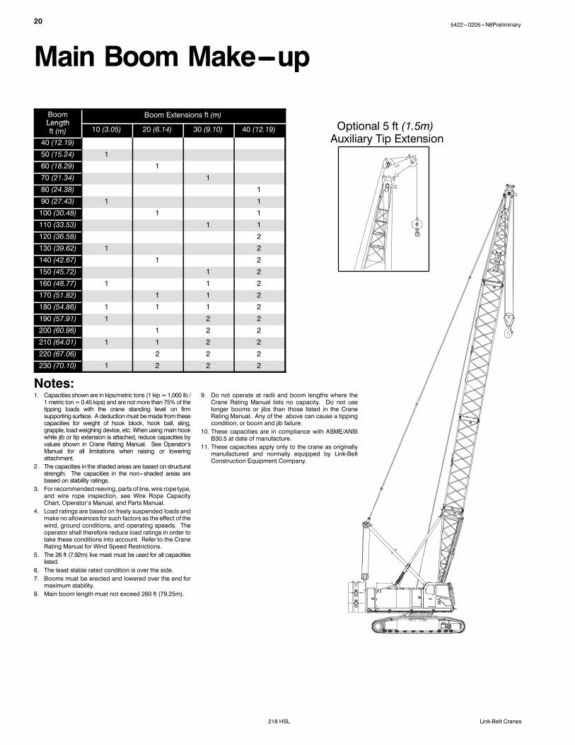
Tube Boom ExtensionsThe following table provides the lengthsavailable and the suggested quantity toobtainmaximumboom in 10 ft (3.05m) in-crements. Midpoint pendant connectionsare required at 100 ft (30.48m) for boomlengthsof 210 ft (64.01m), 220 ft (67.06m),and 230 ft (70.10m).S Polyamide wear blocks on top of eachextension
Tube BoomExtensions Quantity For Max
Boomft m
Boom
10 3.05 1
20 6.10 2
30 9.14 2
40 12.19 2
S Maximum tip height of 233 ft 11 in(71.30m)
S Boom connecting pins storage oneachextension
4 5422---0205---N6Preliminary
218 HSL Link-Belt Cranes
Tubular Jib30--75 ft (9.14---22.86m)
Basic Tube Jib30 ft (9.14m) two---piece design that uti-lizes a 15 ft (4.57m) base section and a15 ft (4.57m) top section with in --- lineconnecting pins on 32 in (0.81m) wideand 24 in (0.61m) deep centers.S 2 in (50.8mm) diameter tubular chordsS One 18.50 in (0.47m) root diametersteel sheave mounted on sealed anti ---friction bearings
S 15 ft (4.57m) jib extensions provide jiblengths of 45 ft (13.72m), 60 ft (18.29m),and 75 ft (22.86m).
S Jib offset angles at 5˚, 15˚, and 25˚S The maximum tip height of boom + jib[200 ft + 75 ft (60.96 + 22.86m)] is278.6 ft (84.92m).
Luffing Boom80--140 ft (24.38---42.67m)
S Common base and extensions asopenthroat boom (“HP” only)
S 5 ft (1.52m) luffing extension requiredfor bail anchor
S Working angles of 90˚, 85˚, 80˚, 75˚,70˚, and 65˚
S Working lengths of 80 ft (24.38m) to140 ft (42.67m)
Luffing Boom ExtensionsThe following table provides the lengthsavailable and the suggested quantity toobtain the maximum luffing boom in 10 ft(3.05m) increments. Midpoint pendantsare not required.
Luffing BoomExtensions Quantity For Max
Boomft m
Boom
10 3.05 1
20 6.10 2
30 9.14 1
40 12.19 1
Note: “HP” type boom must be used.S Rear hoist drum becomes luffing jibhoist
S Optional third drum provides secondworking hoist line, if required.
S Designed for self ---assemblyS Luffing jib hoist bridle and bail can re-main reeved for crane transport
S Job site mobility with attachmentS Rolled out or rolled under erectionmethods
S Compact transport module
Auxiliary Tip Extension5 ft (1.5m)
Designed to use in place of jib to provideclearance between working hoist lines.The extension is equipped with two nylon18 in (45.72cm) root diameter sheavesmounted on sealed anti --- friction bear-ings. Maximum capacity is 18.5 Ton(16.78mt).
Luffing Jib50--140 ft (15.24---42.67m)
Basic Luffing Jib50 ft (15.24m) four---piecedesignutilizesa5 ft (1.52m) luffing boom top section, 20 ft(6.10m) luffing jib base section, 20 ft(6.10m) luffing jib top section, and 10 ft(3.05m) jib extension with in--- line con-necting pins. Jib extensions are 39 in(0.99m) wide and 48 in (1.22m) deep atthe centers.S 25 Ton (22.68mt) maximum capacityS Working lengths of 50 ft (15.24m) to140 ft (42.67m)
S Lugs on base section to attach fan---post transport links
S Two steel 22.50 in (0.57m) diameter luf-fing jib head sheaves
S Two polyamide 21.25 in (0.54m)diameter luffing boom auxiliary headsheaves
S Pin---on nose wheelS Eight---part luffing jib hoistS 1.25 in (31.75mm) diameter type “N”pendants
S Anemometer with in ---cab display
Luffing Jib ExtensionsThe following table provides the lengthsavailable and the suggested quantity toobtain the maximum luffing jib in 10 ft(3.05m) increments. Midpoint pendantsare not required.
Luffing JibExtensions Quantity For Max
Luffing Jibft m
Luffing Jib
10 3.05 1
20 6.10 1
30 9.14 2
S Deflector roller on topof eachextensionS Appropriate length pendantsS Maximum luffing jib tip height of 283 ft(86.26m)
55422---0205---N6Preliminary
218 HSLLink-Belt Cranes
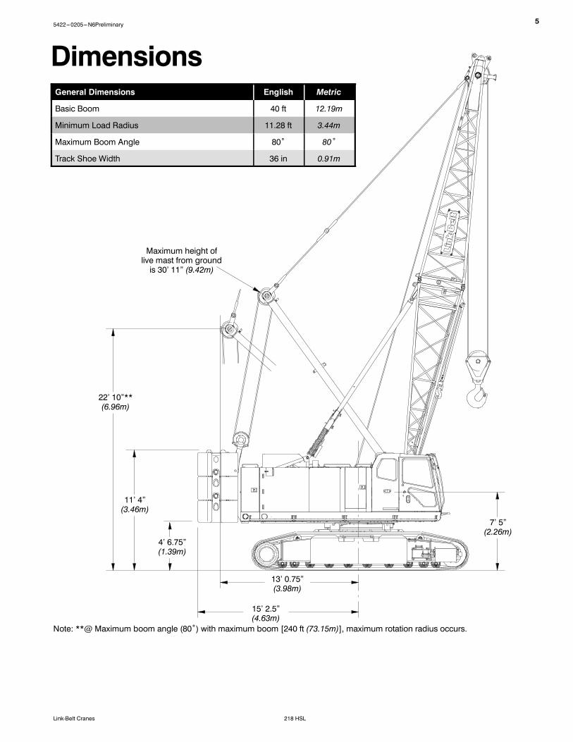
DimensionsGeneral Dimensions English Metric
Basic Boom 40 ft 12.19m
Minimum Load Radius 11.28 ft 3.44m
Maximum Boom Angle 80˚ 80˚
Track Shoe Width 36 in 0.91m
Maximum height oflive mast from groundis 30’ 11” (9.42m)
22’ 10”**(6.96m)
11’ 4”(3.46m)
4’ 6.75”(1.39m)
13’ 0.75”(3.98m)
15’ 2.5”(4.63m)
7’ 5”(2.26m)
Note: **@ Maximum boom angle (80˚) with maximum boom [240 ft (73.15m)], maximum rotation radius occurs.
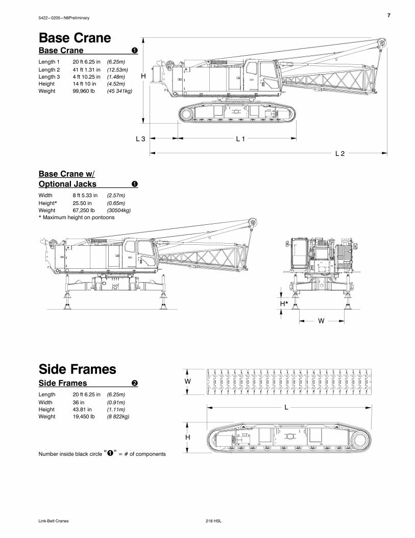
Base CraneLength 1 20 ft 6.25 in (6.25m)Length 2 41 ft 1.31 in (12.53m)Length 3 4 ft 10.25 in (1.48m)Height 14 ft 10 in (4.52m)Weight 99,960 lb (45 341kg)
Side FramesLength 20 ft 6.25 in (6.25m)Width 36 in (0.91m)Height 43.81 in (1.11m)Weight 19,450 lb (8 822kg)
H
L
H
L 1
W
L 3
Base Crane
Side Frames
Base Crane w/Optional JacksWidth 8 ft 5.33 in (2.57m)Height* 25.50 in (0.65m)Weight 67,250 lb (30504kg)* Maximum height on pontoons
W
H*
75422---0205---N6Preliminary
218 HSLLink-Belt Cranes
8 5422---0205---N6Preliminary
218 HSL Link-Belt Cranes
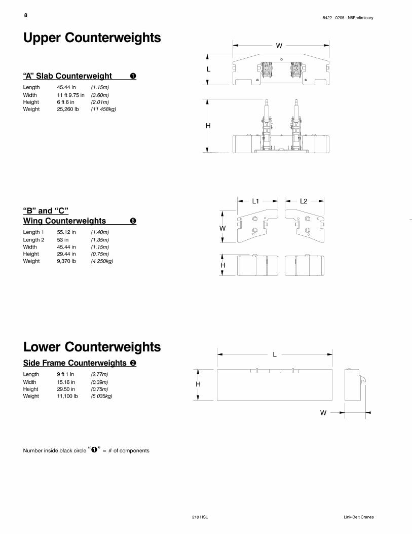
“B” and “C”Wing CounterweightsLength 1 55.12 in (1.40m)Length 2 53 in (1.35m)Width 45.44 in (1.15m)Height 29.44 in (0.75m)Weight 9,370 lb (4 250kg)
Side Frame CounterweightsLength 9 ft 1 in (2.77m)Width 15.16 in (0.39m)Height 29.50 in (0.75m)Weight 11,100 lb (5 035kg)
“A” Slab CounterweightLength 45.44 in (1.15m)Width 11 ft 9.75 in (3.60m)Height 6 ft 6 in (2.01m)Weight 25,260 lb (11 458kg)
Upper Counterweights
Lower Counterweights
W
L
H
W
L1
H
L2
W
L
H
Number inside black circle “ ” = # of components
95422---0205---N6Preliminary
218 HSLLink-Belt Cranes
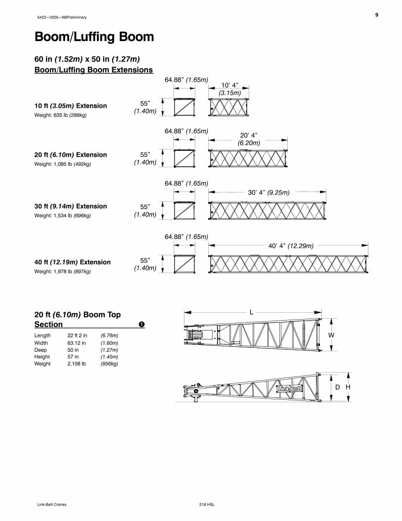
10’ 4”(3.15m)
40 ft (12.19m) ExtensionWeight: 1,978 lb (897kg)
60 in (1.52m) x 50 in (1.27m)Boom/Luffing Boom Extensions
30 ft (9.14m) ExtensionWeight: 1,534 lb (696kg)
10 ft (3.05m) ExtensionWeight: 635 lb (288kg)
20 ft (6.10m) ExtensionWeight: 1,085 lb (492kg)
40’ 4” (12.29m)
30’ 4” (9.25m)
20’ 4”(6.20m)
55”(1.40m)
64.88” (1.65m)
Boom/Luffing Boom
55”(1.40m)
64.88” (1.65m)
55”(1.40m)
64.88” (1.65m)
55”(1.40m)
64.88” (1.65m)
20 ft (6.10m) Boom TopSectionLength 22 ft 2 in (6.76m)Width 63.12 in (1.60m)Deep 50 in (1.27m)Height 57 in (1.45m)Weight 2,108 lb (956kg)
D
L
H
W
10 5422---0205---N6Preliminary
218 HSL Link-Belt Cranes
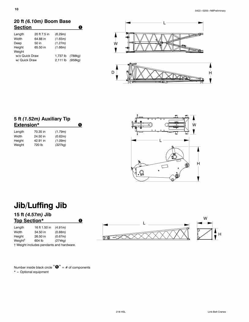
20 ft (6.10m) Boom BaseSectionLength 20 ft 7.5 in (6.29m)Width 64.88 in (1.65m)Deep 50 in (1.27m)Height 65.50 in (1.66m)Weightw/o Quick Draw 1,737 lb (788kg)w/ Quick Draw 2,111 lb (958kg)
L
W
D H
Number inside black circle “ ” = # of components* --- Optional equipment
5 ft (1.52m) Auxiliary TipExtension*Length 70.35 in (1.79m)Width 24.50 in (0.62m)Height 42.91 in (1.09m)Weight 720 lb (327kg)
L
W
H
15 ft (4.57m) JibTop Section*Length 16 ft 1.50 in (4.91m)Width 34.50 in (0.88m)Height 26.50 in (0.67m)Weight† 604 lb (274kg)† Weight includes pendants and hardware.
Jib/Luffing JibW
L
H
115422---0205---N6Preliminary
218 HSLLink-Belt Cranes
Number inside black circle “ ” = # of components* --- Optional equipment
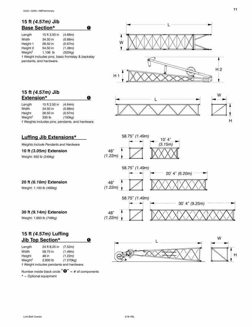
15 ft (4.57m) JibBase Section*Length 15 ft 3.50 in (4.66m)Width 34.50 in (0.88m)Height 1 26.50 in (0.67m)Height 2 54.50 in (1.38m)Weight† 1,106 lb (502kg)† Weight includes pins, basic frontstay & backstaypendants, and hardware.
15 ft (4.57m) JibExtension*Length 15 ft 2.50 in (4.64m)Width 34.50 in (0.88m)Height 26.50 in (0.67m)Weight† 330 lb (150kg)† Weights includes pins, pendants, and hardware.
W
H 1
LW
H
H 2
L
10’ 4”(3.15m)
Luffing Jib Extensions*Weights Include Pendants and Hardware
30 ft (9.14m) ExtensionWeight: 1,650 lb (748kg)
10 ft (3.05m) ExtensionWeight: 550 lb (249kg)
20 ft (6.10m) ExtensionWeight: 1,100 lb (499kg)
30’ 4” (9.25m)
20’ 4” (6.20m)
48”(1.22m)
58.75” (1.49m)
48”(1.22m)
58.75” (1.49m)
48”(1.22m)
58.75” (1.49m)
15 ft (4.57m) LuffingJib Top Section*Length 24 ft 8.25 in (7.52m)Width 58.75 in (1.49m)Height 48 in (1.22m)Weight† 2,800 lb (1 270kg)† Weight includes pendants and hardware.
WL
H
12 5422---0205---N6Preliminary
218 HSL Link-Belt Cranes
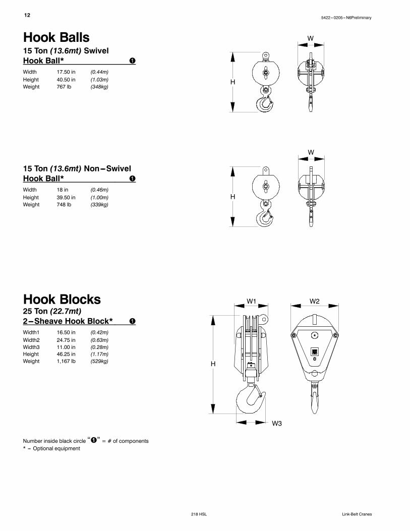
15 Ton (13.6mt) Non---SwivelHook Ball*Width 18 in (0.46m)Height 39.50 in (1.00m)Weight 748 lb (339kg)
Hook Balls
H
W
15 Ton (13.6mt) SwivelHook Ball*Width 17.50 in (0.44m)Height 40.50 in (1.03m)Weight 767 lb (348kg)
H
W
Number inside black circle “ ” = # of components* --- Optional equipment
W1 W2Hook Blocks25 Ton (22.7mt)2---Sheave Hook Block*Width1 16.50 in (0.42m)Width2 24.75 in (0.63m)Width3 11.00 in (0.28m)Height 46.25 in (1.17m)Weight 1,167 lb (529kg) H
W3
135422---0205---N6Preliminary
218 HSLLink-Belt Cranes
W3
W2W1
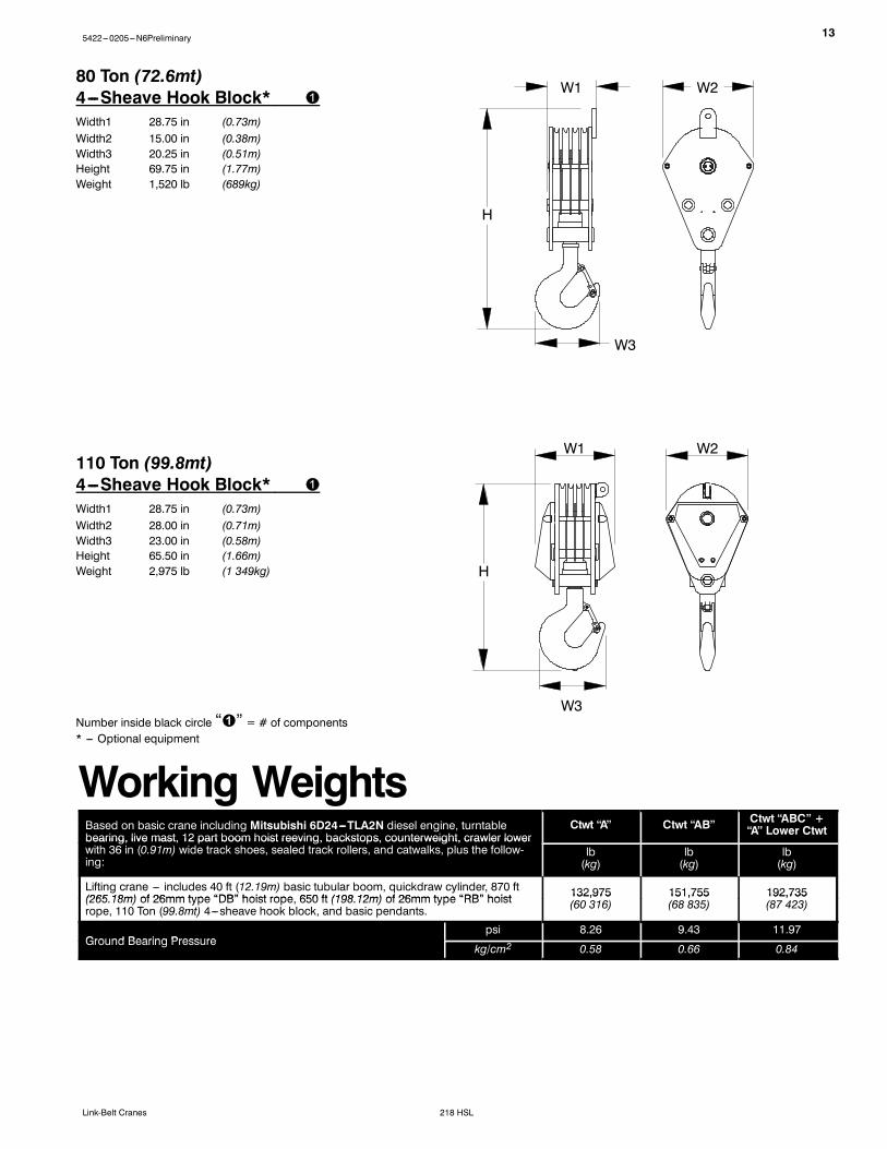
80 Ton (72.6mt)4---Sheave Hook Block*Width1 28.75 in (0.73m)Width2 15.00 in (0.38m)Width3 20.25 in (0.51m)Height 69.75 in (1.77m)Weight 1,520 lb (689kg)
W3
H
Number inside black circle “ ” = # of components* --- Optional equipment
110 Ton (99.8mt)4---Sheave Hook Block*Width1 28.75 in (0.73m)Width2 28.00 in (0.71m)Width3 23.00 in (0.58m)Height 65.50 in (1.66m)Weight 2,975 lb (1 349kg)
H
W1 W2
Working WeightsBased on basic crane including Mitsubishi 6D24---TLA2N diesel engine, turntablebearing, live mast, 12 part boom hoist reeving, backstops, counterweight, crawler lower
Ctwt “A” Ctwt “AB” Ctwt “ABC” +“A” Lower Ctwtbearing, live mast, 12 part boom hoist reeving, backstops, counterweight, crawler lower
with 36 in (0.91m) wide track shoes, sealed track rollers, and catwalks, plus the follow-ing:
lb(kg)
lb(kg)
lb(kg)
Lifting crane --- includes 40 ft (12.19m) basic tubular boom, quickdraw cylinder, 870 ft(265 18m) of 26mm type “DB” hoist rope 650 ft (198 12m) of 26mm type “RB” hoist 132,975 151,755 192,735(265.18m) of 26mm type “DB” hoist rope, 650 ft (198.12m) of 26mm type “RB” hoistrope, 110 Ton (99.8mt) 4---sheave hook block, and basic pendants.
132,975(60 316)
151,755(68 835)
192,735(87 423)
Ground Bearing Pressurepsi 8.26 9.43 11.97
Ground Bearing Pressurekg/cm2 0.58 0.66 0.84
14 5422---0205---N6Preliminary
218 HSL Link-Belt Cranes
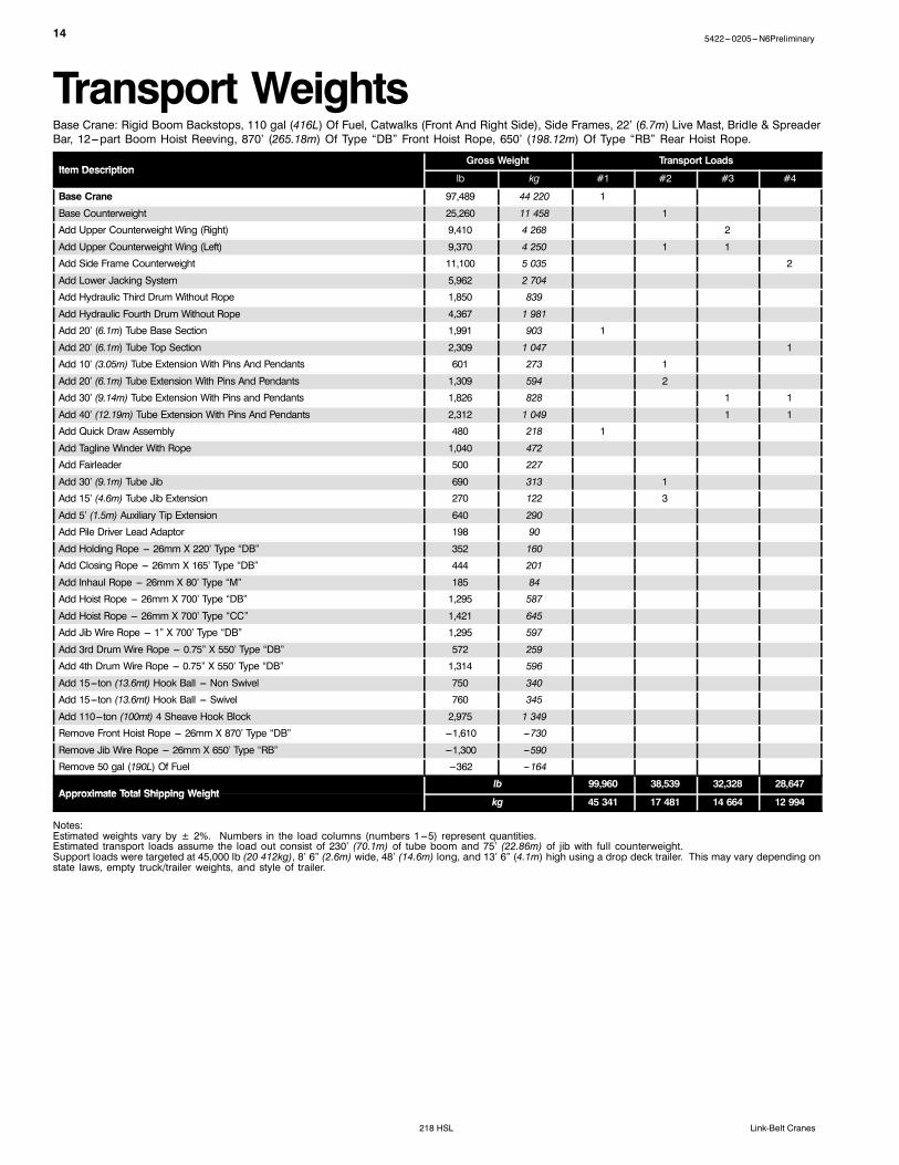
Transport WeightsBase Crane: Rigid Boom Backstops, 110 gal (416L) Of Fuel, Catwalks (Front And Right Side), Side Frames, 22’ (6.7m) Live Mast, Bridle & SpreaderBar, 12---part Boom Hoist Reeving, 870’ (265.18m) Of Type “DB” Front Hoist Rope, 650’ (198.12m) Of Type “RB” Rear Hoist Rope.
Notes:Estimated weights vary by ± 2%. Numbers in the load columns (numbers 1---5) represent quantities.Estimated transport loads assume the load out consist of 230’ (70.1m) of tube boom and 75’ (22.86m) of jib with full counterweight.Support loads were targeted at 45,000 lb (20 412kg), 8’ 6” (2.6m) wide, 48’ (14.6m) long, and 13’ 6” (4.1m) high using a drop deck trailer. This may vary depending onstate laws, empty truck/trailer weights, and style of trailer.
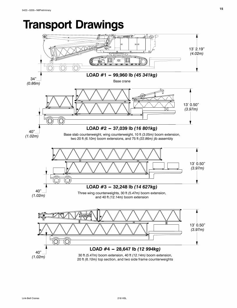
LOAD #4 --- 28,647 lb (12 994kg)30 ft (5.47m) boom extension, 40 ft (12.14m) boom extension,20 ft (6.10m) top section, and two side frame counterweights
two 20 ft (6.10m) boom extensions, and 75 ft (22.86m) jib assembly
40”(1.02m)
13’ 2.19”(4.02m)
13’ 0.50”(3.97m)
13’ 0.50”(3.97m)
16 5422---0205---N6Preliminary
218 HSL Link-Belt Cranes
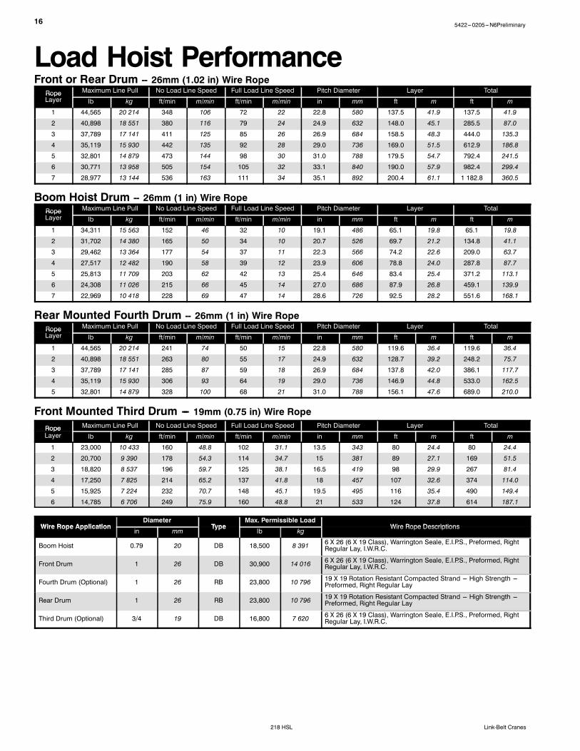
Load Hoist PerformanceFront or Rear Drum -- 26mm (1.02 in) Wire RopeRope Maximum Line Pull No Load Line Speed Full Load Line Speed Pitch Diameter Layer TotalRopeLayer lb kg ft/min m/min ft/min m/min in mm ft m ft m
Boom Hoist Drum -- 26mm (1 in) Wire RopeRope Maximum Line Pull No Load Line Speed Full Load Line Speed Pitch Diameter Layer TotalRopeLayer lb kg ft/min m/min ft/min m/min in mm ft m ft m
Rear Mounted Fourth Drum -- 26mm (1 in) Wire RopeRope Maximum Line Pull No Load Line Speed Full Load Line Speed Pitch Diameter Layer TotalRopeLayer lb kg ft/min m/min ft/min m/min in mm ft m ft m
Front Mounted Third Drum --- 19mm (0.75 in) Wire RopeRope Maximum Line Pull No Load Line Speed Full Load Line Speed Pitch Diameter Layer TotalRopeLayer lb kg ft/min m/min ft/min m/min in mm ft m ft m
Notes:1. Capacities shownare in kips/metric tons (1 kip =1,000 lb /1metric ton=0.45 kips) and are not more than 75% of thetipping loads with the crane standing level on firmsupporting surface. A deductionmust bemade from thesecapacities for weight of hook block, hook ball, sling,grapple, loadweighing device, etc. When using main hookwhile jib or tip extension is attached, reduce capacities byvalues shown in Crane Rating Manual. See Operator’sManual for all limitations when raising or loweringattachment.
2. The capacities in the shaded areas are based on structuralstrength. The capacities in the non---shaded areas arebased on stability ratings.
3. For recommended reeving, parts of line,wire rope type,and wire rope inspection, see Wire Rope CapacityChart, Operator’s Manual, and Parts Manual.
4. Load ratings are based on freely suspended loads andmake no allowances for such factors as the effect of thewind, ground conditions, and operating speeds. Theoperator shall therefore reduce load ratings in order totake these conditions into account. Refer to the CraneRating Manual for Wind Speed Restrictions.
5. The 26 ft (7.92m) live mast must be used for all capacitieslisted.
6. The least stable rated condition is over the side.7. Booms must be erected and lowered over the end formaximum stability.
8. Main boom length must not exceed 260 ft (79.25m).
9. Do not operate at radii and boom lengths where theCrane Rating Manual lists no capacity. Do not uselonger booms or jibs than those listed in the CraneRating Manual. Any of the above can cause a tippingcondition, or boom and jib failure.
10. These capacities are in compliance with ASME/ANSIB30.5 at date of manufacture.
11. These capacities apply only to the crane as originallymanufactured and normally equipped by Link-BeltConstruction Equipment Company.
215422---0205---N6Preliminary
218 HSLLink-Belt Cranes
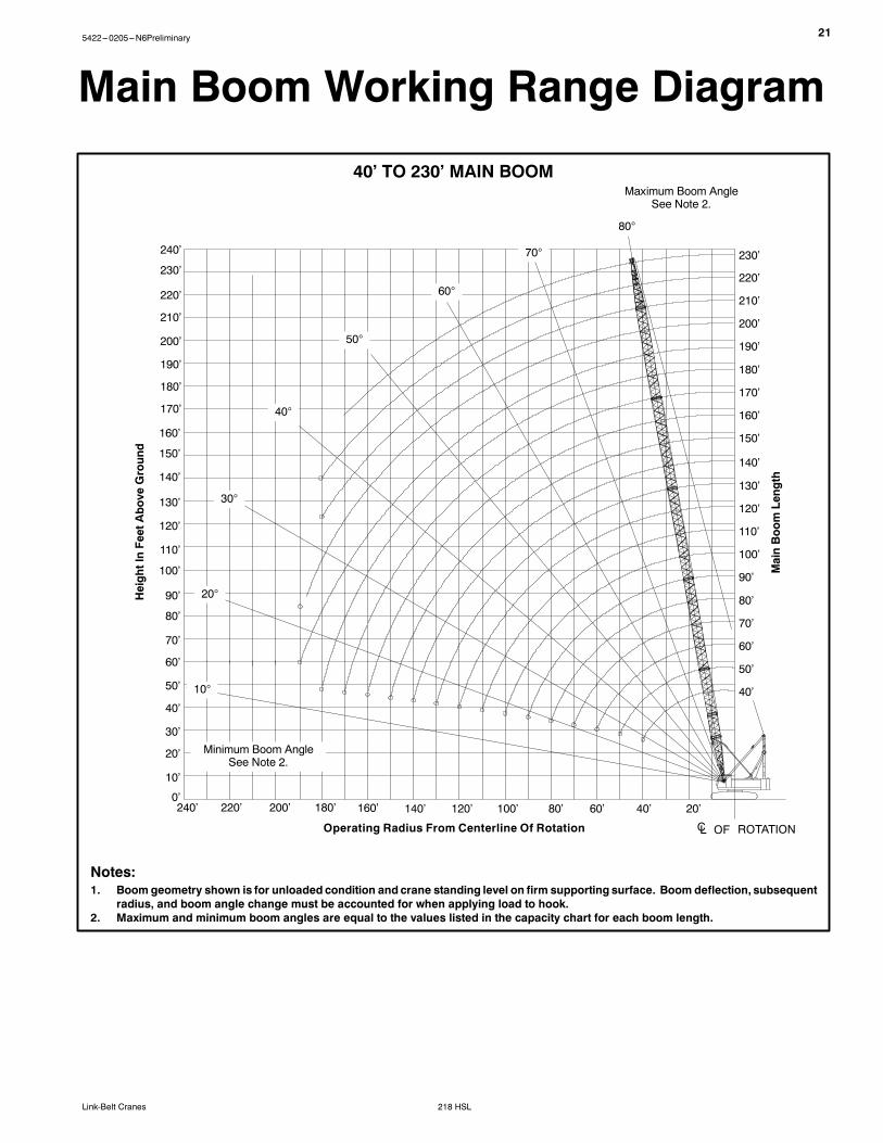
Main Boom Working Range Diagram
40’ TO 230’ MAIN BOOM
Operating Radius From Centerline Of Rotation
Maximum Boom AngleSee Note 2.
MainBoomLength
HeightInFeetAbove
Ground
140’ 120’ 100’ 80’ 60’ 40’ 20’
50’
60’
70’
80’
90’
100’
110’
120’
130’
140’
150’
20’
30’
40’
10’
160’
160’
170’
180’
190’
200’
180’200’220’240’
ROTATION
40’
50’
60’
70’
80’
90’
230’
100’
110’
120’
130’
140’
150’
160’
170’
180’
190’
200’
210’
220’
30°
20°
10°
80°
70°
60°
50°
40°
210’
220’
230’
240’
Minimum Boom AngleSee Note 2.
CL OF
0’
Notes:1. Boom geometry shown is for unloaded condition and crane standing level on firm supporting surface. Boom deflection, subsequent
radius, and boom angle change must be accounted for when applying load to hook.2. Maximum and minimum boom angles are equal to the values listed in the capacity chart for each boom length.
ABC+A [62,820+22,200 lb (28 495+10 070kg)] Counterweight -- Side Frames Extended[All capacities are listed in kips (mt)]
LoadBoom Length --- ft (m)
LoadRadiusft (m)
40(12.2)
50(15.2)
60(18.3)
70(21.3)
80(24.4)
90(27.4)
100(30.5)
110(33.5)
120(36.6)
130(39.6)
11(3.4)
220.0(99.8)
12(3.7)
208.4(94.5)
13(4.0)
195.3(88.6)
14(4.3)
183.4(83.2)
183.4(83.2)
15(4.6)
173.1(78.5)
173.1(78.5)
169.9(77.1)
16(4.9)
163.7(74.3)
163.7(74.3)
163.7(74.3)
17(5.2)
155.4(70.5)
155.4(70.5)
155.4(70.5)
153.6(69.7)
18(5.5)
147.7(67.0)
147.7(67.0)
147.7(67.0)
147.7(67.0)
19(5.8)
137.5(62.4)
137.7(62.5)
137.8(62.5)
137.8(62.5)
136.3(61.8)
20(6.1)
126.6(57.4)
126.7(57.5)
126.8(57.5)
126.8(57.5)
126.7(57.5)
25(7.6)
90.2(40.9)
90.3(41.0)
90.4(41.0)
90.3(41.0)
90.2(40.9)
90.2(40.9)
90.1(40.9)
89.9(40.8)
30(9.1)
69.8(31.7)
69.9(31.7)
69.9(31.7)
69.9(31.7)
69.8(31.7)
69.7(31.6)
69.5(31.5)
69.4(31.5)
69.3(31.4)
69.1(31.3)
35(10.7)
56.7(25.7)
56.8(25.8)
56.8(25.8)
56.8(25.8)
56.7(25.7)
56.5(25.6)
56.4(25.6)
56.3(25.5)
56.1(25.4)
55.9(25.4)
40(12.2)
47.6(21.6)
47.7(21.6)
47.7(21.6)
47.6(21.6)
47.5(21.5)
47.4(21.5)
47.3(21.5)
47.1(21.4)
47.0(21.3)
46.8(21.2)
50(15.2)
35.8(16.2)
35.9(16.3)
35.8(16.2)
35.7(16.2)
35.6(16.1)
35.4(16.1)
35.2(16.0)
35.1(15.9)
34.9(15.8)
60(18.3)
28.5(12.9)
28.4(12.9)
28.3(12.8)
28.2(12.8)
28.0(12.7)
27.9(12.7)
27.7(12.6)
27.5(12.5)
70(21.3)
23.3(10.6)
23.3(10.6)
23.1(10.5)
23.0(10.4)
22.8(10.3)
22.7(10.3)
22.5(10.2)
80(24.4)
19.6(8.9)
19.5(8.8)
19.3(8.8)
19.2(8.7)
19.0(8.6)
18.8(8.5)
90(27.4)
16.7(7.6)
16.5(7.5)
16.4(7.4)
16.2(7.3)
16.0(7.3)
100(30.5)
14.3(6.5)
14.2(6.4)
14.0(6.4)
13.8(6.3)
110(33.5)
12.4(5.6)
12.3(5.6)
12.1(5.5)
120(36.6)
10.8(4.9)
10.6(4.8)
130(39.6)
9.4(4.3)
This material is supplied for reference use only. Operator must refer to in---cab Crane Rating Manual and Operator’s Manual to determine allowablecrane lifting capacities and assembly and operating procedures.
235422---0205---N6Preliminary
218 HSLLink-Belt Cranes
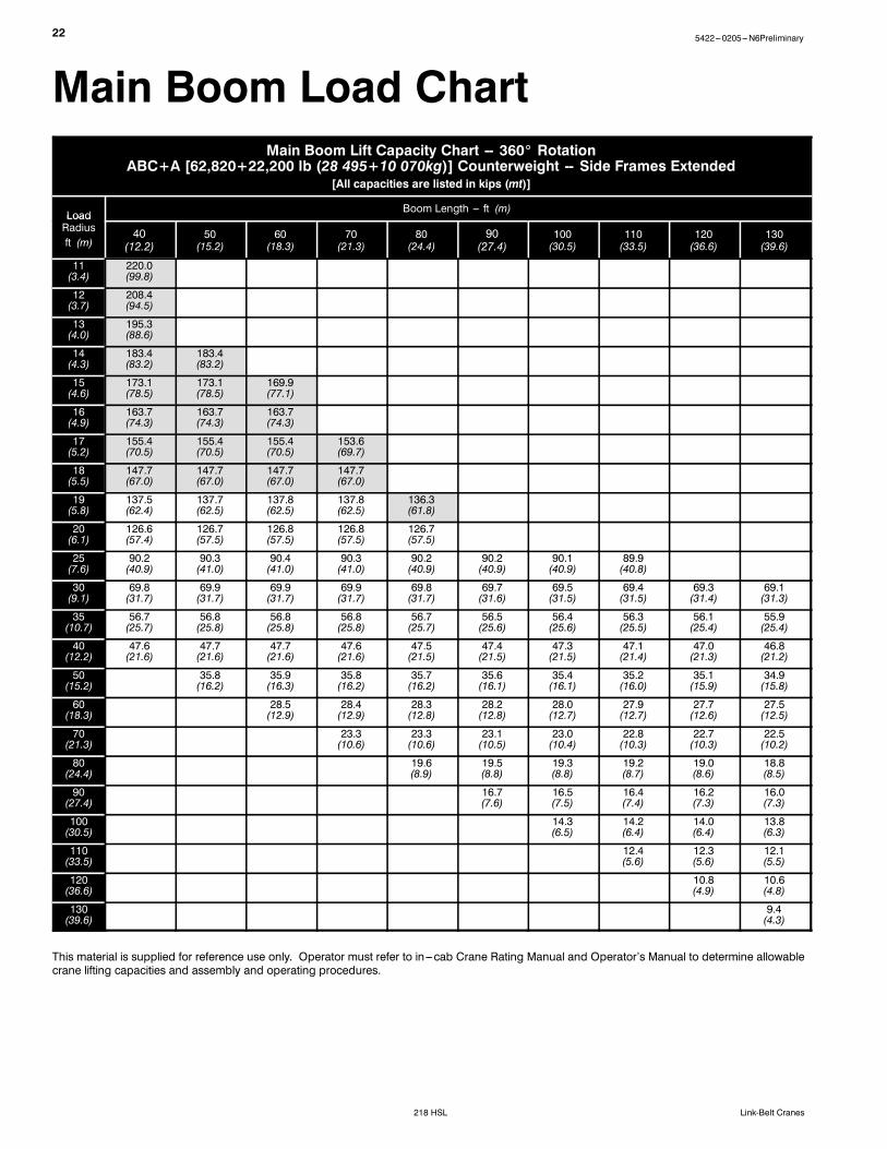
Main Boom Lift Capacity Chart -- 360_ RotationABC+A [62,820+22,200 lb (28 495+10 070kg)] Counterweight -- Side Frames Extended
[All capacities are listed in kips (mt)]
LoadBoom Length --- ft (m)
LoadRadiusft (m)
140(42.7)
150(45.7)
160(48.8)
170(51.8)
180(54.9)
190(57.9)
200(61.0)
210(64.0)
220(67.1)
230(70.1)
25(7.6)
30(9.1)
69.0(31.3)
35(10.7)
55.8(25.3)
55.6(25.2)
55.5(25.2)
55.3(25.1)
40(12.2)
46.6(21.1)
46.5(21.1)
46.3(21.0)
46.1(20.9)
45.9(20.8)
45.8(20.8)
43.1(19.6)
50(15.2)
34.7(15.7)
34.5(15.6)
34.4(15.6)
34.2(15.5)
34.0(15.4)
33.8(15.3)
33.6(15.2)
33.4(15.2)
31.3(14.2)
26.6(12.1)
60(18.3)
27.3(12.4)
27.1(12.3)
27.0(12.2)
26.8(12.2)
26.6(12.1)
26.4(12.0)
26.2(11.9)
26.0(11.8)
24.4(11.1)
23.5(10.7)
70(21.3)
22.3(10.1)
22.1(10.0)
21.9(9.9)
21.7(9.8)
21.5(9.8)
21.3(9.7)
21.1(9.6)
20.9(9.5)
20.7(9.4)
20.5(9.3)
80(24.4)
18.6(8.4)
18.4(8.3)
18.2(8.3)
18.0(8.2)
17.8(8.1)
17.6(8.0)
17.4(7.9)
17.2(7.8)
17.0(7.7)
16.8(7.6)
90(27.4)
15.8(7.2)
15.7(7.1)
15.5(7.0)
15.3(6.9)
15.1(6.8)
14.9(6.8)
14.7(6.7)
14.4(6.5)
14.2(6.4)
14.0(6.4)
100(30.5)
13.7(6.2)
13.5(6.1)
13.3(6.0)
13.1(5.9)
12.9(5.9)
12.7(5.8)
12.5(5.7)
12.2(5.5)
12.0(5.4)
11.8(5.4)
110(33.5)
11.9(5.4)
11.7(5.3)
11.5(5.2)
11.3(5.1)
11.1(5.0)
10.9(4.9)
10.7(4.9)
10.5(4.8)
10.3(4.7)
10.0(4.5)
120(36.6)
10.4(4.7)
10.3(4.7)
10.1(4.6)
9.9(4.5)
9.7(4.4)
9.5(4.3)
9.2(4.2)
9.0(4.1)
8.8(4.0)
8.6(3.9)
130(39.6)
9.2(4.2)
9.0(4.1)
8.8(4.0)
8.6(3.9)
8.4(3.8)
8.2(3.7)
8.0(3.6)
7.8(3.5)
7.6(3.4)
7.4(3.4)
140(42.7)
8.2(3.7)
8.0(3.6)
7.8(3.5)
7.6(3.4)
7.4(3.4)
7.2(3.3)
7.0(3.2)
6.8(3.1)
6.5(2.9)
6.3(2.9)
150(45.7)
7.1(3.2)
6.9(3.1)
6.7(3.0)
6.5(2.9)
6.3(2.9)
6.1(2.8)
5.9(2.7)
5.7(2.6)
5.4(2.4)
160(48.8)
6.1(2.8)
5.9(2.7)
5.7(2.6)
5.5(2.5)
5.3(2.4)
5.1(2.3)
4.9(2.2)
4.7(2.1)
170(51.8)
5.2(2.4)
5.0(2.3)
4.8(2.2)
4.6(2.1)
4.4(2.0)
4.2(1.9)
4.0(1.8)
180(54.9)
4.2(1.9)
4.2(1.9)
4.0(1.8)
3.8(1.7)
3.6(1.6)
3.4(1.5)
190(57.9)
3.4(1.5)
3.5(1.6)
3.2(1.5)
3.0(1.4)
2.8(1.3)
200(61.0)
2.6(1.2)
2.6(1.2)
2.6(1.2)
2.4(1.1)
210(64.0)
220(67.1)
230(70.1)
This material is supplied for reference use only. Operator must refer to in---cab Crane Rating Manual and Operator’s Manual to determine allowablecrane lifting capacities and assembly and operating procedures.
24 5422---0205---N6Preliminary
218 HSL Link-Belt Cranes
Jib Attachment Make---up
JibLengthft (m)
Jib ExtensionsBasic FrontstayPendantsRequired
Pairs Of FrontstayExtension Pendants
Requiredft (m)
15 ft (4.57 m) 63 ft 5 in (19.33m) 14 ft 6 in (4.42m)
30 (9.15) 1
45 (13.72) 1 1 1
60 (18.29) 2 1 2
75 (22.86) 3 1 3
Notes:1. Capacities shownare in kips/metric tons (1 kip =1,000 lb /1metric ton=0.45 kips) and are not more than 75% of thetipping loads with the crane standing level on a firmsupporting surface.
2. A deduction must be made from these capacities for theweight of themain boomhook block or hook ball, jib hookblock or hook ball, slings, grapples, load weighing devices,etc. When using main hook while jib is attached, reducecapacities by values shown in Crane Rating Manual. SeeOperator’s Manual for all limitations when raising orlowering attachment.
3. The capacities in the shaded areas are based on structuralstrength. The capacities in the non---shaded areas arebased on stability ratings.
4. Load ratings are based on freely suspended loads andmake no allowances for such factors as the effect of thewind, ground conditions, and operating speeds. Theoperator shall therefore reduce load ratings in order totake these conditions into account. Refer to the CraneRating Manual for Wind Speed Restrictions.
5. These capacities are for “ABC+A” counterweight.6. These capacities are for 360˚ working areas.7. These capacities are for 30---75 ft (9.15---22.86m) jiblengths only.
8. The jib cannot be used on boom lengths over 200 ft(60.96m).
9. The least stable rated condition is over the side.10. These capacities are in compliance with ASME/ANSIB30.5 at date of manufacture.
11. These capacities apply only to the crane as originallymanufactured and normally equipped by Link-BeltConstruction Equipment Company.
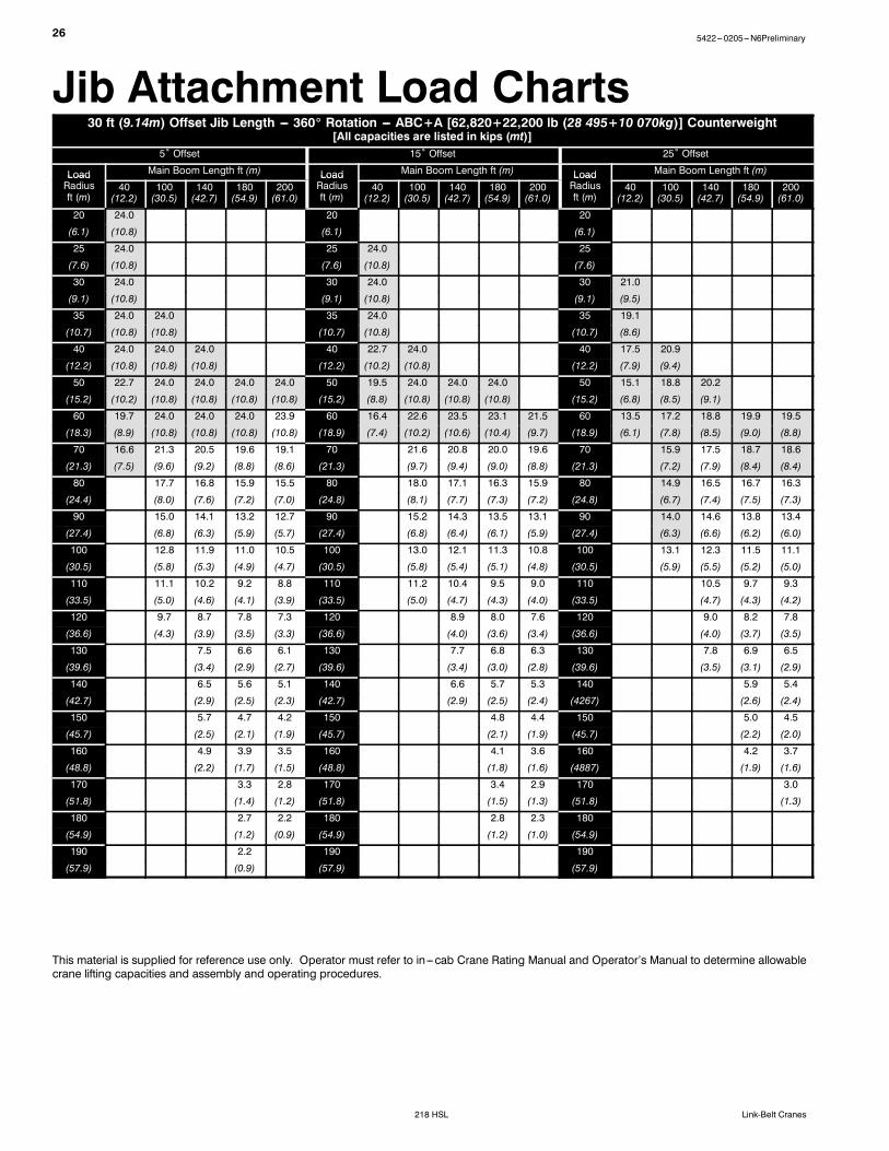
255422---0205---N6Preliminary
218 HSLLink-Belt Cranes
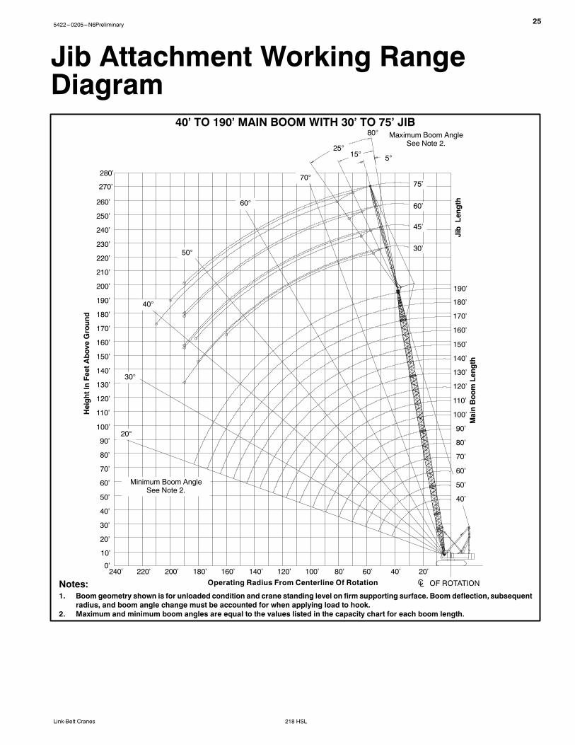
Jib Attachment Working RangeDiagram
Notes:1. Boom geometry shown is for unloaded condition and crane standing level on firm supporting surface. Boom deflection, subsequent
radius, and boom angle change must be accounted for when applying load to hook.2. Maximum and minimum boom angles are equal to the values listed in the capacity chart for each boom length.
MainBoomLength
HeightInFeetAbove
Ground
40’ TO 190’ MAIN BOOM WITH 30’ TO 75’ JIBMaximum Boom Angle
See Note 2.
Operating Radius From Centerline Of Rotation CL OF ROTATION
This material is supplied for reference use only. Operator must refer to in---cab Crane Rating Manual and Operator’s Manual to determine allowablecrane lifting capacities and assembly and operating procedures.
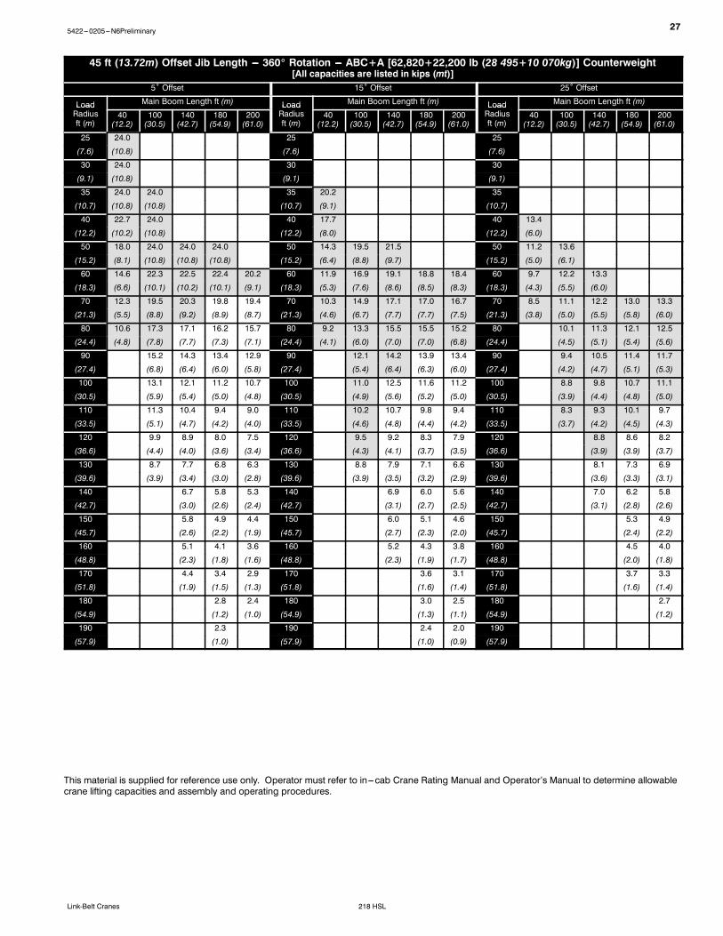
275422---0205---N6Preliminary
218 HSLLink-Belt Cranes
45 ft (13.72m) Offset Jib Length --- 360_ Rotation --- ABC+A [62,820+22,200 lb (28 495+10 070kg)] Counterweight[All capacities are listed in kips (mt)]
5˚ Offset 15˚ Offset 25˚ Offset
Load Main Boom Length ft (m) Load Main Boom Length ft (m) Load Main Boom Length ft (m)LoadRadiusft (m)
This material is supplied for reference use only. Operator must refer to in---cab Crane Rating Manual and Operator’s Manual to determine allowablecrane lifting capacities and assembly and operating procedures.
28 5422---0205---N6Preliminary
218 HSL Link-Belt Cranes
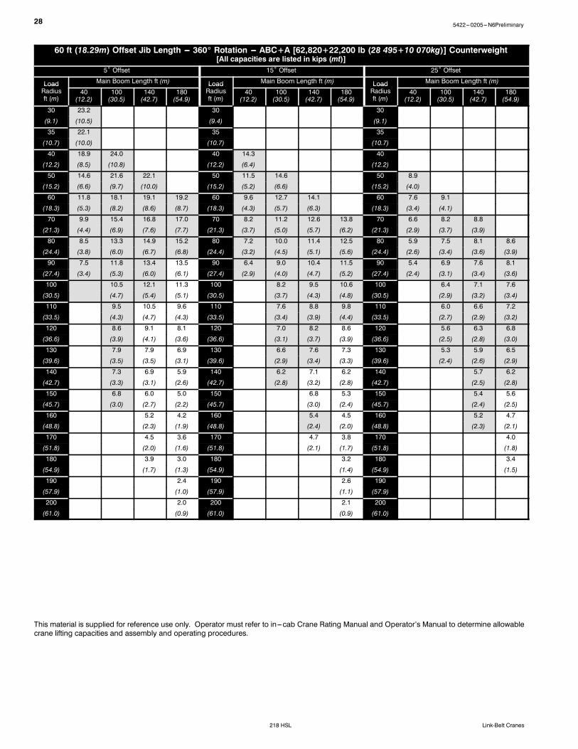
60 ft (18.29m) Offset Jib Length --- 360_ Rotation --- ABC+A [62,820+22,200 lb (28 495+10 070kg)] Counterweight[All capacities are listed in kips (mt)]
5˚ Offset 15˚ Offset 25˚ Offset
Load Main Boom Length ft (m) Load Main Boom Length ft (m) Load Main Boom Length ft (m)LoadRadiusft (m)
This material is supplied for reference use only. Operator must refer to in---cab Crane Rating Manual and Operator’s Manual to determine allowablecrane lifting capacities and assembly and operating procedures.
295422---0205---N6Preliminary
218 HSLLink-Belt Cranes
75 ft (22.86m) Offset Jib Length --- 360_ Rotation --- ABC+A [62,820+22,200 lb (28 495+10 070kg)] Counterweight[All capacities are listed in kips (mt)]
5˚ Offset 15˚ Offset 25˚ Offset
Load Main Boom Length ft (m) Load Main Boom Length ft (m) Load Main Boom Length ft (m)LoadRadiusft (m)
This material is supplied for reference use only. Operator must refer to in---cab Crane Rating Manual and Operator’s Manual to determine allowablecrane lifting capacities and assembly and operating procedures.
30 5422---0205---N6Preliminary
218 HSL Link-Belt Cranes
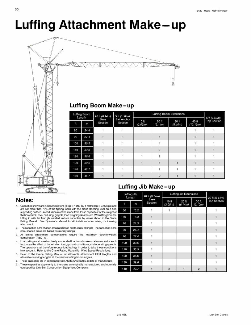
Luffing Attachment Make---up
Luffing Boom Make---upLuffing BoomLength 20 ft (6.14m) 5 ft (1.52m)
Luffing Boom Extensions5 ft (1 52m)Length 20 ft (6.14m)
Base5 ft (1.52m)Bail Anchor 5 ft (1.52m)
T S tift m
BaseSection
Bail AnchorSection 10 ft
(3.05m)20 ft(6.14m)
30 ft(9.10m)
40 ft(12.19m)
5 t ( 5 )Top Section
80 24.4 1 1 1 1 1
90 27.4 1 1 1 1 1
100 30.5 1 1 1 1 1 1
110 33.5 1 1 2 1 1
120 36.6 1 1 1 2 1 1
130 39.6 1 1 1 1 1 1 1
140 42.7 1 1 2 1 1 1
150 45.7 1 1 1 2 1 1 1
Luffing Jib Make---upLuffing JibLength 20 ft (6.14m)
Luffing Jib Extensions20 ft (6 14m)Length 20 ft (6.14m)
Base 20 ft (6.14m)T S ti
ft mBaseSection 10 ft
(3.05m)20 ft(6.14m)
30 ft(9.10m)
20 ft (6.14m)Top Section
50 15.2 1 1 1
60 18.3 1 1
70 21.3 1 1
80 24.4 1 1
90 27.4 1 1
100 30.5 1 1
110 33.5 1 1
120 36.6 1 1
130 39.6 1 1
140 42.7 1 2 1 2 1
Notes:1. Capacities shownare in kips/metric tons (1 kip=1,000 lb / 1metric ton =0.45 kips) andare not more than 75% of the tipping loads with the crane standing level on a firmsupporting surface. A deduction must be made from these capacities for the weight ofthehookblock,hookball, sling,grapple, loadweighingdevices,etc. When lifting from theluffing jib with the fixed jib installed, reduce capacities by values shown in the CraneRating Manual. See Operator’s Manual for all limitations when raising or loweringattachment.
2. Thecapacities in the shadedareasarebased onstructural strength. Thecapacities in thenon---shaded areas are based on stability ratings.
3. All luffing attachment combinations require the maximum counterweightcombination “ABC+A”.
4. Load ratingsarebasedon freely suspended loadsandmakenoallowances for suchfactors as the effect of the wind on load, ground conditions, and operating speeds.The operator shall therefore reduce load ratings in order to take these conditionsinto account. Refer to the Crane Rating Manual for Wind Speed Restrictions.
5. Refer to the Crane Rating Manual for allowable attachment liftoff lengths andallowable working lengths at the various luffing boom angles.
6. These capacities are in compliance with ASME/ANSI B30.5 at date of manufacture.7. These capacities apply only to the crane as originally manufactured and normallyequipped by Link-Belt Construction Equipment Company.
315422---0205---N6Preliminary
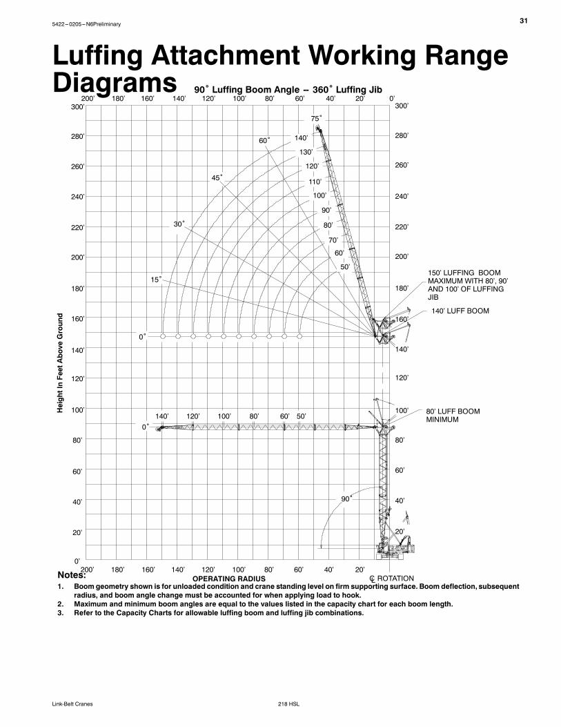
218 HSLLink-Belt Cranes
90˚ Luffing Boom Angle -- 360˚ Luffing Jib
Luffing Attachment Working RangeDiagrams
40’60’80’ 20’100’200’ 180’ 160’ 140’ 120’
40’60’80’ 20’100’200’ 180’ 160’ 140’ 120’ 0’
280’
300’
140’
160’
180’
200’
220’
240’
260’
20’
40’
60’
80’
100’
120’
0’
75˚
30˚
15˚
0˚
0˚
90˚
CL ROTATION
45˚
60˚ 140’
130’
120’
110’
100’
90’
80’
70’
60’
50’
140’ 120’ 100’ 80’ 60’ 50’
20’
40’
60’
80’
100’
120’
140’
160’
180’
200’
220’
240’
260’
280’
300’
80’ LUFF BOOMMINIMUM
140’ LUFF BOOM
150’ LUFFING BOOMMAXIMUM WITH 80’, 90’AND 100’ OF LUFFINGJIB
OPERATING RADIUSNotes:1. Boom geometry shown is for unloaded condition and crane standing level on firm supporting surface. Boom deflection, subsequent
radius, and boom angle change must be accounted for when applying load to hook.2. Maximum and minimum boom angles are equal to the values listed in the capacity chart for each boom length.3. Refer to the Capacity Charts for allowable luffing boom and luffing jib combinations.
HeightInFeetAbove
Ground
32 5422---0205---N6Preliminary
218 HSL Link-Belt Cranes
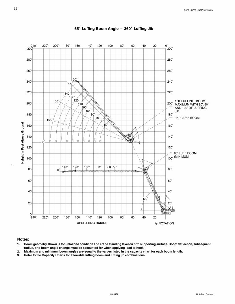
65˚ Luffing Boom Angle -- 360˚ Luffing Jib
4
OPERATING RADIUS CL ROTATION
40’60’80’ 20’100’200’ 180’ 160’ 140’ 120’
50’
40’60’80’ 20’100’200’ 180’ 160’ 140’ 120’ 0’
280’
300’
140’
160’
180’
200’
220’
240’
260’
20’
40’
60’
80’
100’
120’
0’
30˚
15˚
0˚
0˚
50’
65˚
220’
280’
300’
140’
160’
180’
200’
220’
240’
260’
20’
40’
60’
80’
100’
120’
80’ LUFF BOOM(MINIMUM)
220’
60’80’100’120’140’
60’70’
80’90’
100’
130’140’
240’
240’
50˚
110’120’
140’ LUFF BOOM
45˚
150’ LUFFING BOOMMAXIMUM WITH 80’, 90’AND 100’ OF LUFFINGJIB
Notes:1. Boom geometry shown is for unloaded condition and crane standing level on firm supporting surface. Boom deflection, subsequent
radius, and boom angle change must be accounted for when applying load to hook.2. Maximum and minimum boom angles are equal to the values listed in the capacity chart for each boom length.3. Refer to the Capacity Charts for allowable luffing boom and luffing jib combinations.
This material is supplied for reference use only. Operator must refer to in---cab Crane Rating Manual and Operator’s Manual to determine allowablecrane lifting capacities and assembly and operating procedures.
34 5422---0205---N6Preliminary
218 HSL Link-Belt Cranes
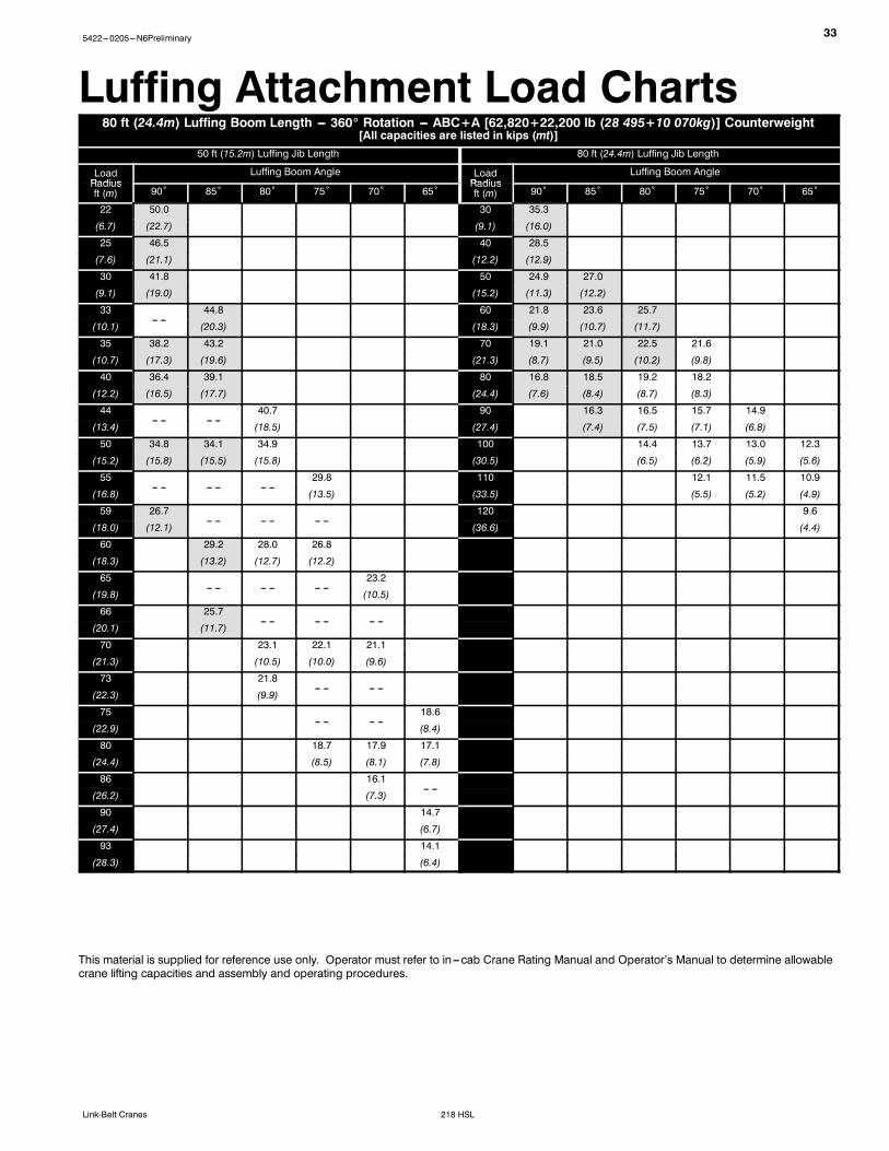
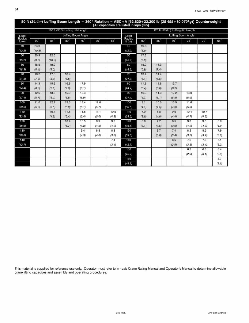
80 ft (24.4m) Luffing Boom Length --- 360_ Rotation --- ABC+A [62,820+22,200 lb (28 495+10 070kg)] Counterweight[All capacities are listed in kips (mt)]
100 ft (30.5) Luffing Jib Length 120 ft (36.6m) Luffing Jib Length
This material is supplied for reference use only. Operator must refer to in---cab Crane Rating Manual and Operator’s Manual to determine allowablecrane lifting capacities and assembly and operating procedures.
355422---0205---N6Preliminary
218 HSLLink-Belt Cranes
80 ft (24.4m) Luffing Boom Length --- 360_ Rotation --- ABC+A [62,820+22,200 lb (28 495+10 070kg)] Counterweight[All capacities are listed in kips (mt)]
This material is supplied for reference use only. Operator must refer to in---cab Crane Rating Manual and Operator’s Manual to determine allowablecrane lifting capacities and assembly and operating procedures.
36 5422---0205---N6Preliminary
218 HSL Link-Belt Cranes
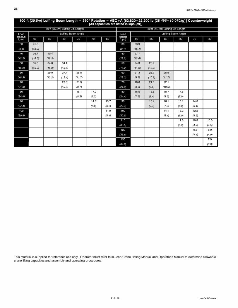
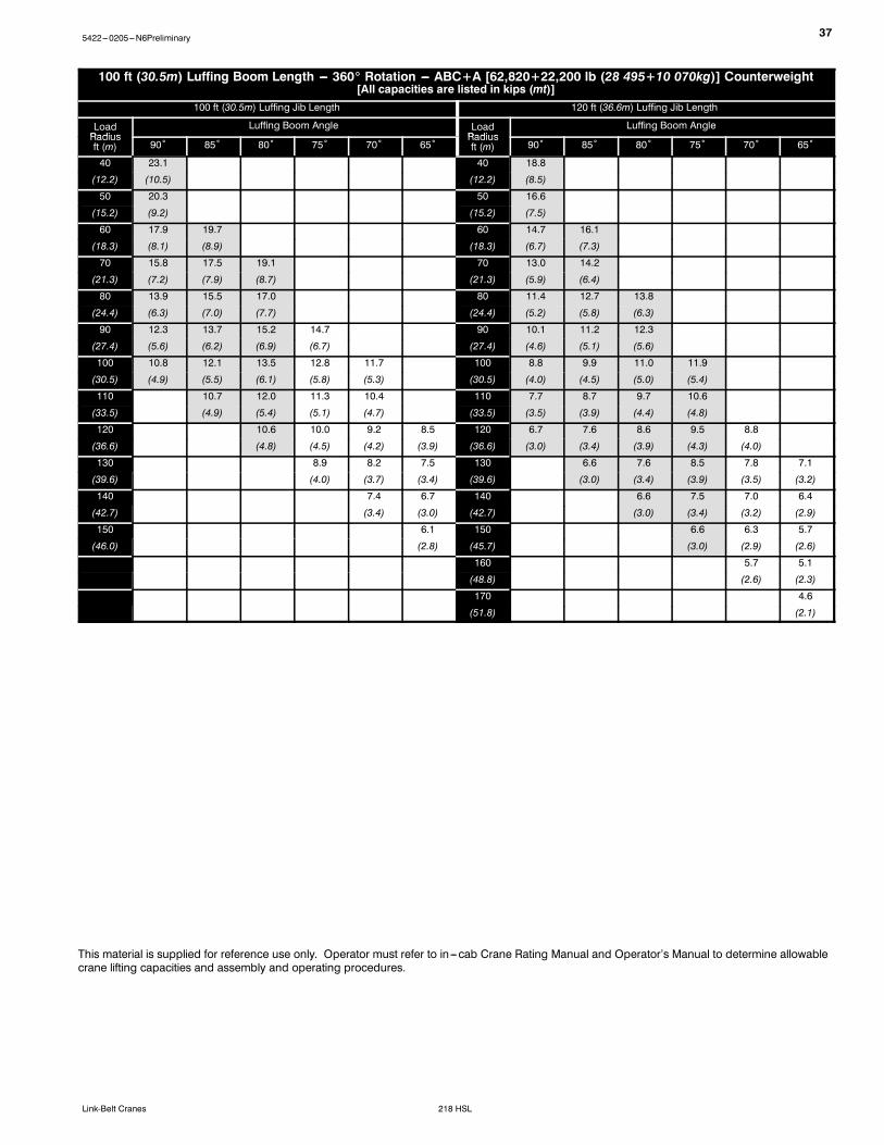
100 ft (30.5m) Luffing Boom Length --- 360_ Rotation --- ABC+A [62,820+22,200 lb (28 495+10 070kg)] Counterweight[All capacities are listed in kips (mt)]
50 ft (15.2m) Luffing Jib Length 80 ft (24.4m) Luffing Jib Length
This material is supplied for reference use only. Operator must refer to in---cab Crane Rating Manual and Operator’s Manual to determine allowablecrane lifting capacities and assembly and operating procedures.
375422---0205---N6Preliminary
218 HSLLink-Belt Cranes
100 ft (30.5m) Luffing Boom Length --- 360_ Rotation --- ABC+A [62,820+22,200 lb (28 495+10 070kg)] Counterweight[All capacities are listed in kips (mt)]
100 ft (30.5m) Luffing Jib Length 120 ft (36.6m) Luffing Jib Length
This material is supplied for reference use only. Operator must refer to in---cab Crane Rating Manual and Operator’s Manual to determine allowablecrane lifting capacities and assembly and operating procedures.
38 5422---0205---N6Preliminary
218 HSL Link-Belt Cranes
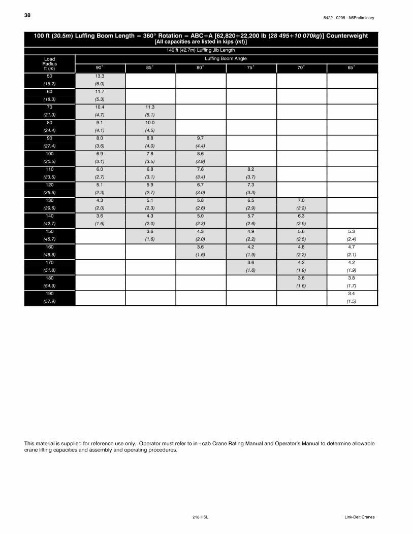
100 ft (30.5m) Luffing Boom Length --- 360_ Rotation --- ABC+A [62,820+22,200 lb (28 495+10 070kg)] Counterweight[All capacities are listed in kips (mt)]
This material is supplied for reference use only. Operator must refer to in---cab Crane Rating Manual and Operator’s Manual to determine allowablecrane lifting capacities and assembly and operating procedures.
395422---0205---N6Preliminary
218 HSLLink-Belt Cranes
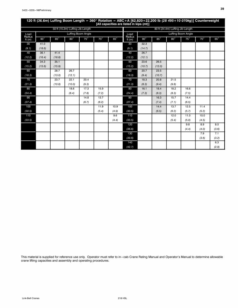
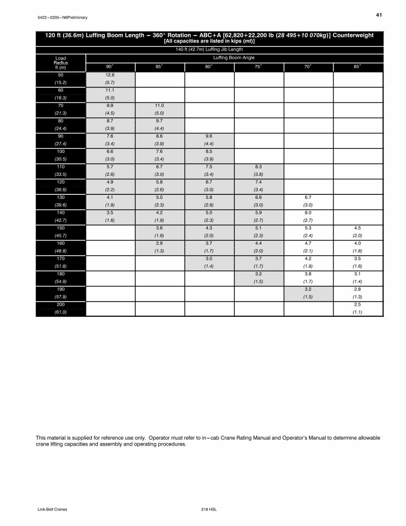
120 ft (36.6m) Luffing Boom Length --- 360_ Rotation --- ABC+A [62,820+22,200 lb (28 495+10 070kg)] Counterweight[All capacities are listed in kips (mt)]
50 ft (15.2m) Luffing Jib Length 80 ft (24.4m) Luffing Jib Length
This material is supplied for reference use only. Operator must refer to in---cab Crane Rating Manual and Operator’s Manual to determine allowablecrane lifting capacities and assembly and operating procedures.
40 5422---0205---N6Preliminary
218 HSL Link-Belt Cranes
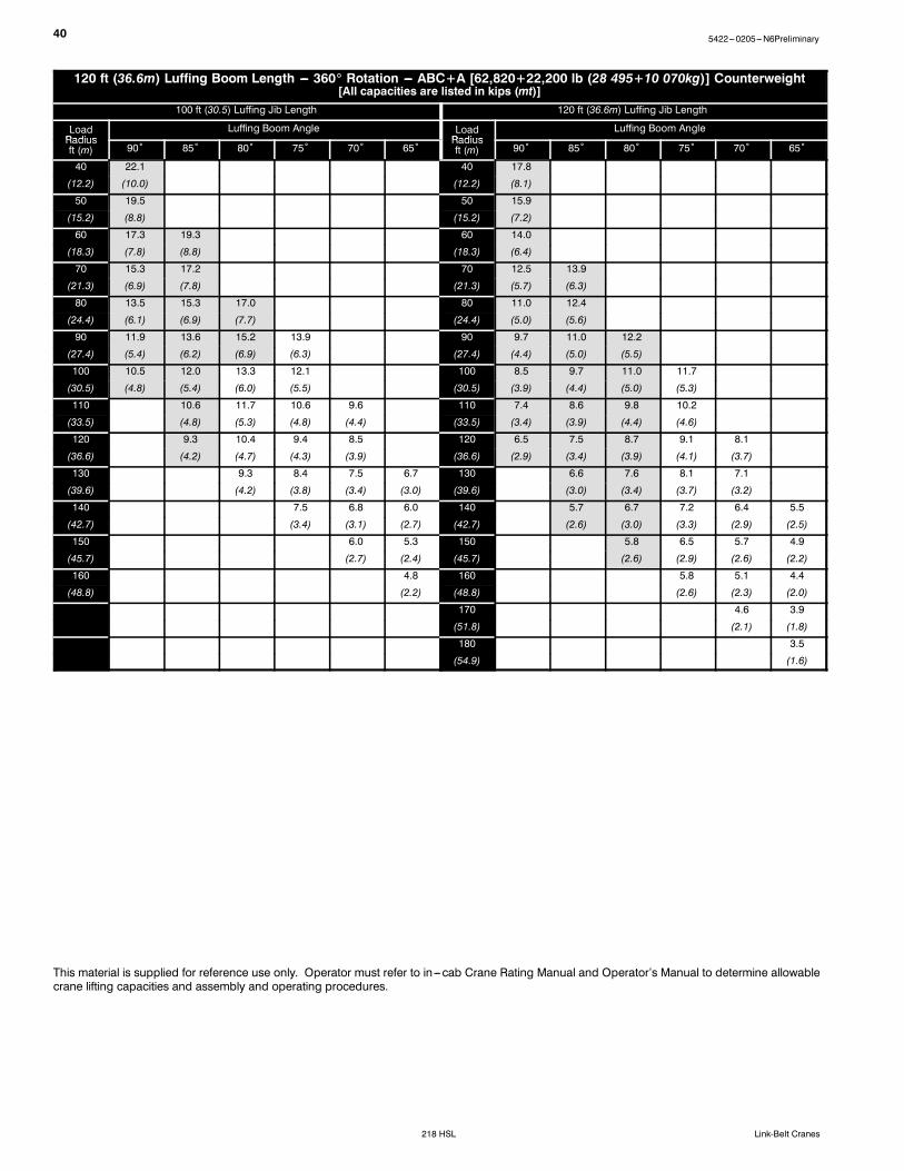
120 ft (36.6m) Luffing Boom Length --- 360_ Rotation --- ABC+A [62,820+22,200 lb (28 495+10 070kg)] Counterweight[All capacities are listed in kips (mt)]
100 ft (30.5) Luffing Jib Length 120 ft (36.6m) Luffing Jib Length
This material is supplied for reference use only. Operator must refer to in---cab Crane Rating Manual and Operator’s Manual to determine allowablecrane lifting capacities and assembly and operating procedures.
415422---0205---N6Preliminary
218 HSLLink-Belt Cranes
120 ft (36.6m) Luffing Boom Length --- 360_ Rotation --- ABC+A [62,820+22,200 lb (28 495+10 070kg)] Counterweight[All capacities are listed in kips (mt)]
This material is supplied for reference use only. Operator must refer to in---cab Crane Rating Manual and Operator’s Manual to determine allowablecrane lifting capacities and assembly and operating procedures.
42 5422---0205---N6Preliminary
218 HSL Link-Belt Cranes
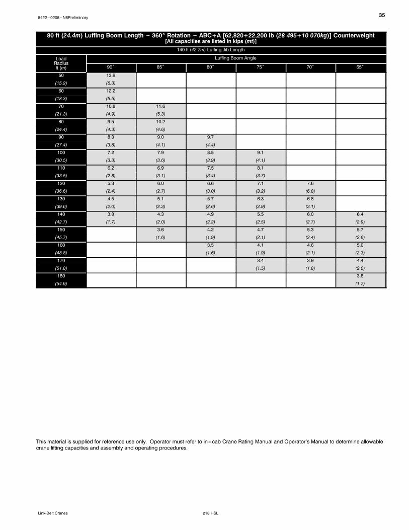
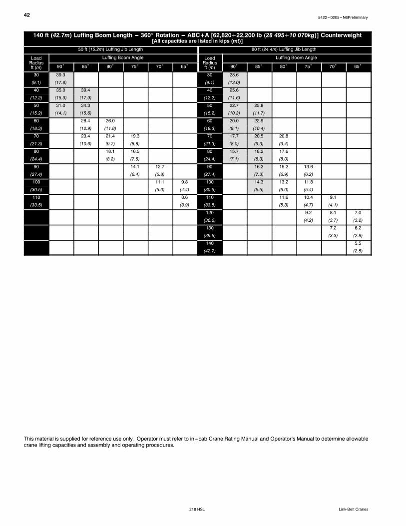
140 ft (42.7m) Luffing Boom Length --- 360_ Rotation --- ABC+A [62,820+22,200 lb (28 495+10 070kg)] Counterweight[All capacities are listed in kips (mt)]
50 ft (15.2m) Luffing Jib Length 80 ft (24.4m) Luffing Jib Length
This material is supplied for reference use only. Operator must refer to in---cab Crane Rating Manual and Operator’s Manual to determine allowablecrane lifting capacities and assembly and operating procedures.
435422---0205---N6Preliminary
218 HSLLink-Belt Cranes
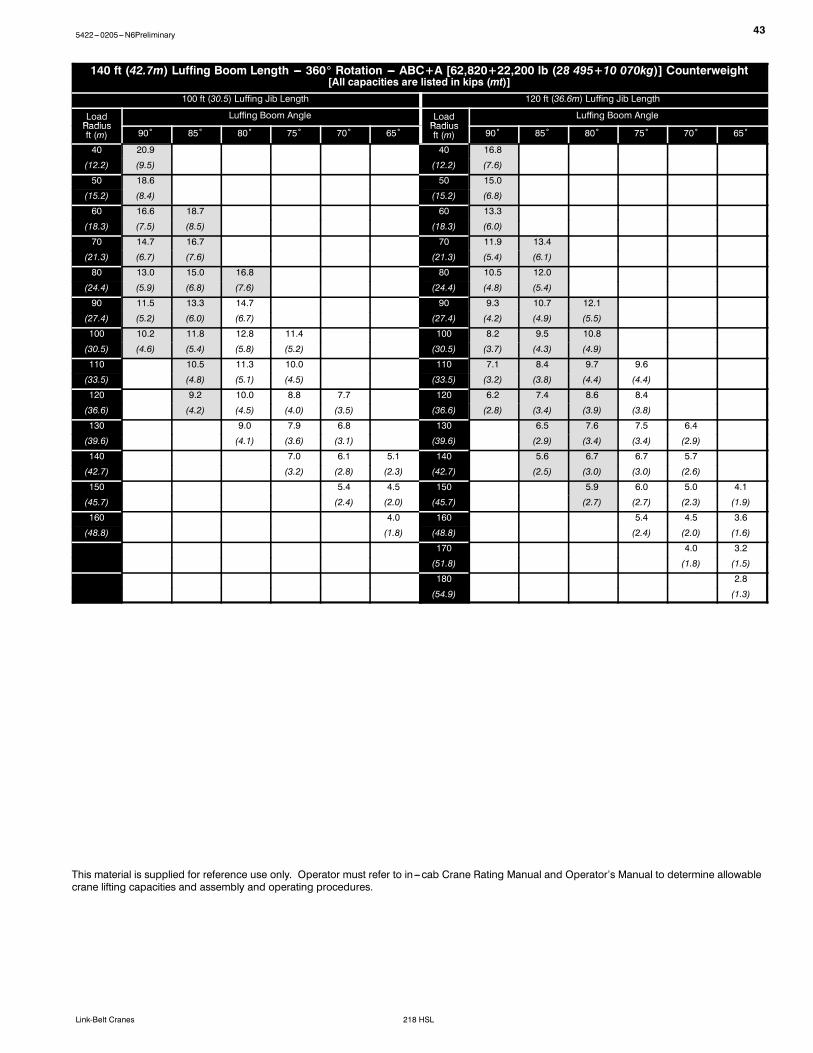
140 ft (42.7m) Luffing Boom Length --- 360_ Rotation --- ABC+A [62,820+22,200 lb (28 495+10 070kg)] Counterweight[All capacities are listed in kips (mt)]
100 ft (30.5) Luffing Jib Length 120 ft (36.6m) Luffing Jib Length
This material is supplied for reference use only. Operator must refer to in---cab Crane Rating Manual and Operator’s Manual to determine allowablecrane lifting capacities and assembly and operating procedures.
44 5422---0205---N6Preliminary
218 HSL Link-Belt Cranes
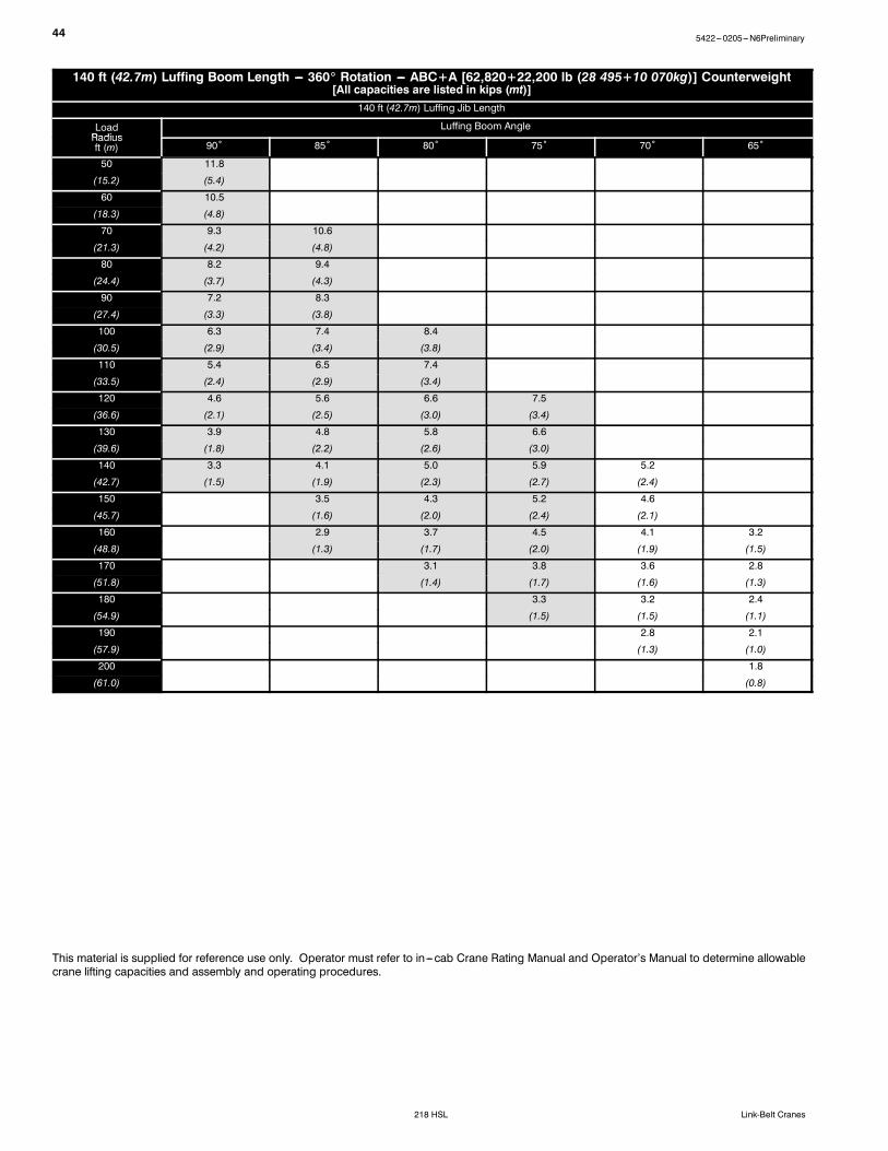
140 ft (42.7m) Luffing Boom Length --- 360_ Rotation --- ABC+A [62,820+22,200 lb (28 495+10 070kg)] Counterweight[All capacities are listed in kips (mt)]
This material is supplied for reference use only. Operator must refer to in---cab Crane Rating Manual and Operator’s Manual to determine allowablecrane lifting capacities and assembly and operating procedures.
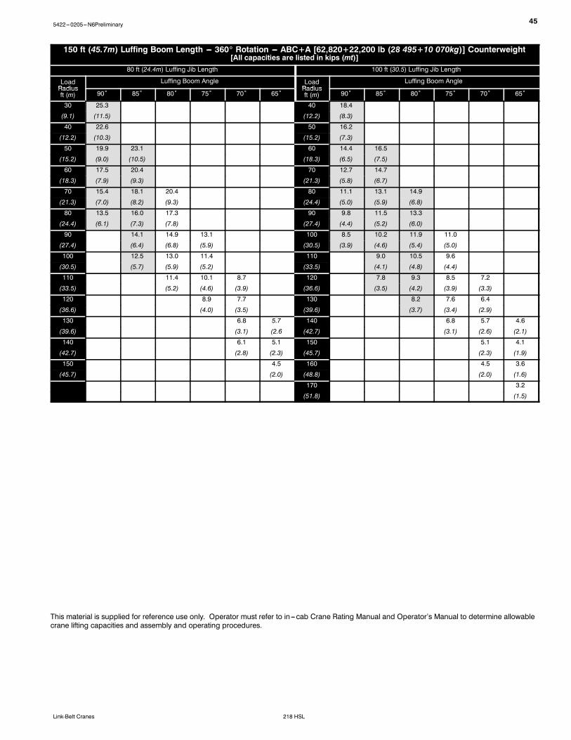
455422---0205---N6Preliminary
218 HSLLink-Belt Cranes
150 ft (45.7m) Luffing Boom Length --- 360_ Rotation --- ABC+A [62,820+22,200 lb (28 495+10 070kg)] Counterweight[All capacities are listed in kips (mt)]
80 ft (24.4m) Luffing Jib Length 100 ft (30.5) Luffing Jib Length
This material is supplied for reference use only. Operator must refer to in---cab Crane Rating Manual and Operator’s Manual to determine allowablecrane lifting capacities and assembly and operating procedures.
46 5422---0205---N6Preliminary
218 HSL Link-Belt Cranes
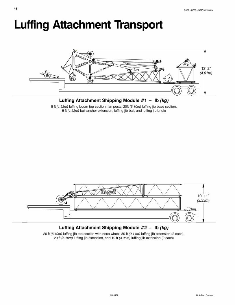
Luffing Attachment Transport
10’ 11”(3.33m)
13’ 2”(4.01m)
Luffing Attachment Shipping Module #1 --- lb (kg)5 ft (1.52m) luffing boom top section, fan posts, 20ft (6.10m) luffing jib base section,
5 ft (1.52m) bail anchor extension, luffing jib bail, and luffing jib bridle
Luffing Attachment Shipping Module #2 --- lb (kg)20 ft (6.10m) luffing jib top section with nose wheel, 30 ft (9.14m) luffing jib extension (2 each),
20 ft (6.10m) luffing jib extension, and 10 ft (3.05m) luffing jib extension (2 each)
475422---0205---N6Preliminary
218 HSLLink-Belt Cranes
This Page Intentionally Blank
5422---0205---N6Preliminary
218 HSL Link-Belt Cranes
Link-Belt Construction Equipment Company Lexington, Kentucky www.linkbelt.comLink-Belt is a registered trademark. Copyright 2005. We are constantly improving our products and therefore reserve the right to change designs and specifications.