XXIX ENFMC - Annals of Optics 2006 Tridimensional Laser Engraving of Industrial Injection Moulds for Fresnel Surface Generation Allan Bereczki , Giuseppe A. Cirino* and Spero Penha Morato LaserTools Tecnologia Ltda. - www.lasertools.com.br – São Paulo, SP [email protected]Abstract We developed a method for generating a three-dimensional surface by laser ablation of successive layers of a hard steel substrate using a Q-switched Nd:YAG laser marking system driven by a scanning head. This development included the creation of a computational method to obtain level curves and for the generation of a suitable filling of these curves with the laser system. The level curves were then imported to proper file formats utilizing the laser’s graphic program that also allowed the development of optimal laser processing parameters to do the engraving. The input process was a grayscale bitmap representing a surface, with the value of each pixel (a value between 0 and 255) corresponding to the depth of the surface in the position (x,y) of the pixel. This numerical process allowed the generation of surfaces utilizing programs like MATLAB by direct micromachining the substrate, once a grayscale bitmap output is obtained. An optical polishing with an ultra-sound device was applied after the laser ablation to reduce the rugosity of the surface that resulted in surfaces with specular reflection. This method was used in the production of a Fresnel lens array mould with spatial filtering for passive infrared motion sensors with satisfactory results. Introduction Laser technology has attracted a great number of people interested in industrial applications, mainly in metallurgy and electronics. In a global market a fierce competition induces the appearance of products that have the laser as one of their most important tools for value aggregation. Industrial application of lasers, mainly in sheet metal cutting, welding and marking are well-established techniques [1 ,2].Lasers are efficient marking and engraving tools and their application dominate sectors such as plastics, metals, alloys, silicon, ceramics, satisfying requirements of speed, quality, flexibility and price. Some of these qualities are not seen in traditional technologies. Lasers are now substituting traditional engraving methods in the mould making industry. Amongst the laser systems that are currently used in industry for marking and engraving, the most popular is the continuously pumped and Q-switched Nd:YAG laser. These systems are the ones with highest peak power outputs specially required for marking and engraving [1]. This high peak power characteristic is especially interesting when engraving metals and alloys with high hardness numbers and when one needs high graphic resolution of engraving. High peak power characteristics are also important since they allow that a large number of metals, their alloys and a wide range of painted or pigmented plastics can be marked. The combination of Nd:YAG lasers with Q-switching devices and scanning heads that divert the laser beam in a xy plane [3], have the ability of high speed marking any kind of material in a computer controlled way duplicating any vetorial graphic image including lines with variable width with precision down to 25 microns. Besides this fact, any graphic element (ideogram, logo, etc.) can be immediately altered by the computer before the next marking job takes place. The image that is going to be marked in a piece is generated by a graphic software that is exported to a dedicated software that controls the laser and other components of the marking equipment like shutters, Q-switchers and scanners. The job duration is determined basically by the text quantity and the image complexity. Marking systems include, besides the Nd:YAG laser cavity, the lamp power supply, primary cooling circuit, RF power supply (Q-switcher), scanning head, a xyz milling base with optical rules for increased precision in positioning, micro computer and a CAM type software. Graphic data to be engraved in a piece are created, edited and manipulated utilizing CAD software. It is important to understand the system operational basis, its parameterization and requirements for the creation and edition of vector files that will be used in the laser processing. To obtain an efficient marking process, knot points, fillings and contours must be carefully *Present address: HoloPhotonics Equipamentos Óticos e Eletrônicos Ltda-ME. -ParqTec - São Carlos - SP
Transcript
XXIX ENFMC - Annals of Optics 2006
Tridimensional Laser Engraving of Industrial Injection Moulds for Fresnel Surface Generation
Allan Bereczki, Giuseppe A. Cirino* and Spero Penha Morato
LaserTools Tecnologia Ltda. - www.lasertools.com.br – São Paulo, SP [email protected]
Abstract We developed a method for generating a three-dimensional surface by laser ablation of successive layers of a hard steel substrate using a Q-switched Nd:YAG laser marking system driven by a scanning head. This development included the creation of a computational method to obtain level curves and for the generation of a suitable filling of these curves with the laser system. The level curves were then imported to proper file formats utilizing the laser’s graphic program that also allowed the development of optimal laser processing parameters to do the engraving. The input process was a grayscale bitmap representing a surface, with the value of each pixel (a value between 0 and 255) corresponding to the depth of the surface in the position (x,y) of the pixel. This numerical process allowed the generation of surfaces utilizing programs like MATLAB by direct micromachining the substrate, once a grayscale bitmap output is obtained. An optical polishing with an ultra-sound device was applied after the laser ablation to reduce the rugosity of the surface that resulted in surfaces with specular reflection. This method was used in the production of a Fresnel lens array mould with spatial filtering for passive infrared motion sensors with satisfactory results.
Introduction Laser technology has attracted a great number of people interested in industrial applications, mainly in metallurgy and electronics. In a global market a fierce competition induces the appearance of products that have the laser as one of their most important tools for value aggregation. Industrial application of lasers, mainly in sheet metal cutting, welding and marking are well-established techniques [1 ,2].Lasers are efficient marking and engraving tools and their application dominate sectors such as plastics, metals, alloys, silicon, ceramics, satisfying requirements of speed, quality, flexibility and price. Some of these qualities are not seen in traditional technologies.
Lasers are now substituting traditional engraving methods in the mould making industry. Amongst the laser systems that are currently used in industry for marking and engraving, the most popular is the continuously pumped and Q-switched Nd:YAG laser. These systems are the ones with highest peak power outputs specially required for marking and engraving [1]. This high peak power characteristic is especially interesting when engraving metals and alloys with high hardness numbers and when one needs high graphic resolution of engraving. High peak power characteristics are also important since they allow that a large number of metals, their alloys and a wide range of painted or pigmented plastics can be marked.
The combination of Nd:YAG lasers with Q-switching devices and scanning heads that divert the laser beam in a xy plane [3], have the ability of high speed marking any kind of material in a computer controlled way duplicating any vetorial graphic image including lines with variable width with precision down to 25 microns. Besides this fact, any graphic element (ideogram, logo, etc.) can be immediately altered by the computer before the next marking job takes place. The image that is going to be marked in a piece is generated by a graphic software that is exported to a dedicated software that controls the laser and other components of the marking equipment like shutters, Q-switchers and scanners. The job duration is determined basically by the text quantity and the image complexity.
Marking systems include, besides the Nd:YAG laser cavity, the lamp power supply, primary cooling circuit, RF power supply (Q-switcher), scanning head, a xyz milling base with optical rules for increased precision in positioning, micro computer and a CAM type software. Graphic data to be engraved in a piece are created, edited and manipulated utilizing CAD software. It is important to understand the system operational basis, its parameterization and requirements for the creation and edition of vector files that will be used in the laser processing. To obtain an efficient marking process, knot points, fillings and contours must be carefully
*Present address: HoloPhotonics Equipamentos Óticos e Eletrônicos Ltda-ME. -ParqTec - São Carlos - SP
XXIX ENFMC - Annals of Optics 2006
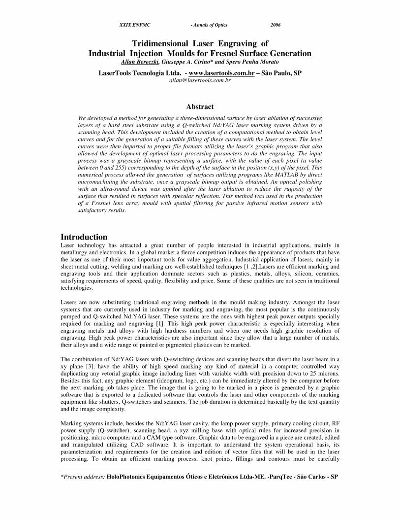
manipulated in the file that contains the vetorial graphic. Figure 1 shows a schematic diagram of the laser cavity coupled to a beam delivering system composed by a scanning head that diverts the beam into a xy planned focus the beam through a f-theta flat field lens.
The method we built is based on that described by Alessandro in [4], but it was based on a bitmap input instead of a stl file. The first attempt to engrave a 3D surface from a grayscale bitmap comprised the creation of a program that converted the bitmap file in a stl file and then the application of the method [4], but for the bitmap resolution required, the stl file generated had a huge size, what did it impracticable.
Figure 1: Schematic of a laser marking and engraving system
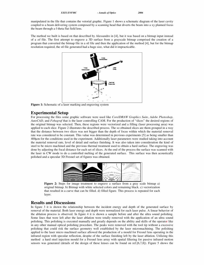
Experimental Setup For processing the files some graphic software were used like CorelDRAW Graphics Suite, Adobe Photoshop, AutoCAD, and Fobagraf that is the laser controlling CAM. For the production of “slices” the desired regions of the original bitmap was selected. Then, these regions were vectorized and a filling (laser processing area) was applied to each slice. Figure 2 illustrates the described process. The so obtained slices are them grouped in a way that the distance between two slices was not bigger than the depth of focus within which the material removal rate was considered to be constant. This value was determined in previous experiments [5] as being smaller than 400µm for the conditions used in the experiment. Additionally laser parameters were studied taking into account the material removal rate, level of detail and surface finishing. It was also taken into consideration the kind of steel to be micro machined and the previous thermal treatment used to obtain a hard surface. The engraving was done by adjusting the focal distance for each set of slices. At the end of the process the surface was scanned with the laser in CW mode to do a controlled melting of the generated surface. This surface was then acoustically polished and a specular 3D Fresnel set of figures was obtained.
Figure 2: Steps for image treatment to engrave a surface from a gray scale bitmap a) original bitmap. b) Bitmap with white selected colors and remaining black. c) vectorization that resulted in a curve that can be filled. d) filled figure. This process is repeated for each layer.
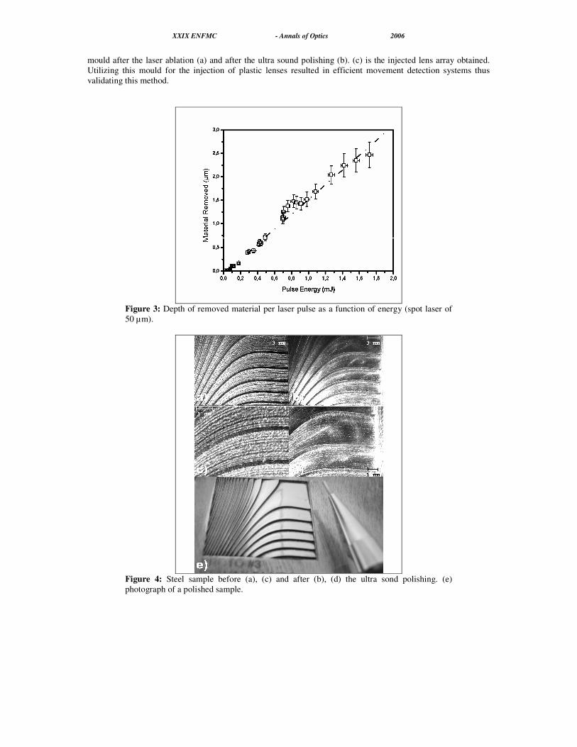
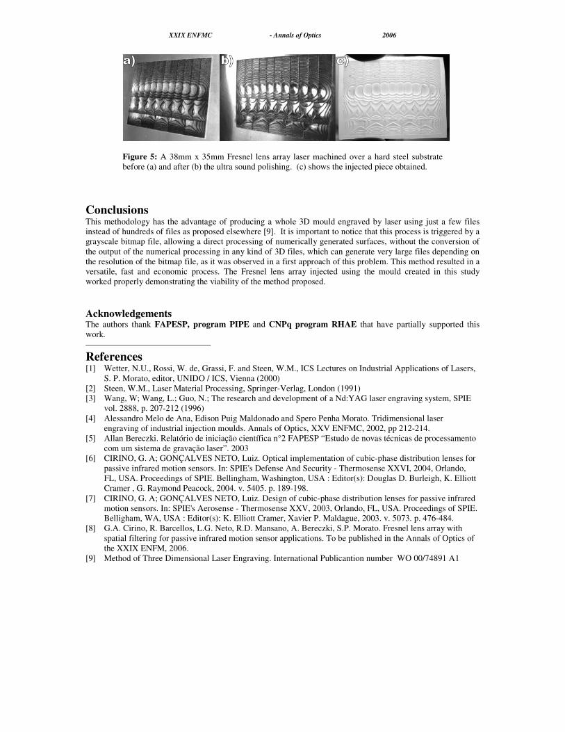
Results and Discussions In figure 3 it is shown the relationship between the incident energy and depth of the generated surface by removal of the material. Both laser energy and depth were normalized for each laser pulse. A linear behavior of the ablation process is observed. In figure 4 it is shown a sample before and after the ultra sound polishing. Some lines that were left after the laser ablation were totally removed with the application of an ultra sound polishing. This polishing is executed manually and greatly depends on the ability and skills of the operator like in any other manual optical polishing procedure. The peaks were removed with the tool tip without a excessive polishing that could risk the surface geometry well established by the laser micromachining. The polishing applied to the laser micro machined surface allowed the production of a mould for Fresnel lens operating in the infrared region with specular reflection, despite of the surface finishing left by the laser ablation. Utilizing this method a hard steel injection mould for a Fresnel lens array with spatial filtering for passive infrared motion sensors was generated (details of the design of these lenses can be found on ref.[6,7,8]). Figure 5 shows the
XXIX ENFMC - Annals of Optics 2006
mould after the laser ablation (a) and after the ultra sound polishing (b). (c) is the injected lens array obtained. Utilizing this mould for the injection of plastic lenses resulted in efficient movement detection systems thus validating this method.
Figure 3: Depth of removed material per laser pulse as a function of energy (spot laser of 50 µm).
Figure 4: Steel sample before (a), (c) and after (b), (d) the ultra sond polishing. (e) photograph of a polished sample.
XXIX ENFMC - Annals of Optics 2006
Figure 5: A 38mm x 35mm Fresnel lens array laser machined over a hard steel substrate before (a) and after (b) the ultra sound polishing. (c) shows the injected piece obtained.
Conclusions This methodology has the advantage of producing a whole 3D mould engraved by laser using just a few files instead of hundreds of files as proposed elsewhere [9]. It is important to notice that this process is triggered by a grayscale bitmap file, allowing a direct processing of numerically generated surfaces, without the conversion of the output of the numerical processing in any kind of 3D files, which can generate very large files depending on the resolution of the bitmap file, as it was observed in a first approach of this problem. This method resulted in a versatile, fast and economic process. The Fresnel lens array injected using the mould created in this study worked properly demonstrating the viability of the method proposed.
Acknowledgements The authors thank FAPESP, program PIPE and CNPq program RHAE that have partially supported this work.
References [1] Wetter, N.U., Rossi, W. de, Grassi, F. and Steen, W.M., ICS Lectures on Industrial Applications of Lasers,
S. P. Morato, editor, UNIDO / ICS, Vienna (2000) [2] Steen, W.M., Laser Material Processing, Springer-Verlag, London (1991) [3] Wang, W; Wang, L.; Guo, N.; The research and development of a Nd:YAG laser engraving system, SPIE
vol. 2888, p. 207-212 (1996) [4] Alessandro Melo de Ana, Edison Puig Maldonado and Spero Penha Morato. Tridimensional laser
engraving of industrial injection moulds. Annals of Optics, XXV ENFMC, 2002, pp 212-214. [5] Allan Bereczki. Relatório de iniciação científica n°2 FAPESP “Estudo de novas técnicas de processamento
com um sistema de gravação laser”. 2003 [6] CIRINO, G. A; GONÇALVES NETO, Luiz. Optical implementation of cubic-phase distribution lenses for
passive infrared motion sensors. In: SPIE's Defense And Security - Thermosense XXVI, 2004, Orlando, FL, USA. Proceedings of SPIE. Bellingham, Washington, USA : Editor(s): Douglas D. Burleigh, K. Elliott Cramer , G. Raymond Peacock, 2004. v. 5405. p. 189-198.
[7] CIRINO, G. A; GONÇALVES NETO, Luiz. Design of cubic-phase distribution lenses for passive infrared motion sensors. In: SPIE's Aerosense - Thermosense XXV, 2003, Orlando, FL, USA. Proceedings of SPIE. Belligham, WA, USA : Editor(s): K. Elliott Cramer, Xavier P. Maldague, 2003. v. 5073. p. 476-484.
[8] G.A. Cirino, R. Barcellos, L.G. Neto, R.D. Mansano, A. Bereczki, S.P. Morato. Fresnel lens array with spatial filtering for passive infrared motion sensor applications. To be published in the Annals of Optics of the XXIX ENFM, 2006.
[9] Method of Three Dimensional Laser Engraving. International Publicantion number WO 00/74891 A1