113
Version 4.82 Revision A December 2013 ICD Trimble OEM BD9xx GNSS Receiver Family 1

Version 4.82Revision ADecember 2013
ICD
Trimble OEM BD9xxGNSS Receiver Family
1

Corporate OfficeTrimble Navigation LimitedIntegrated Technologies510 DeGuigne DriveSunnyvale, CA 94085USAwww.trimble.com/gnss-inertialEmail: [email protected]
Legal Notices©2006–2013, Trimble Navigation Limited. All rights reserved.Trimble and the Globe & Triangle logo are trademarks of TrimbleNavigation Limited, registered in the United States and in othercountries. CMR+, EVEREST,Maxwell, and Zephyr are trademarks ofTrimble Navigation Limited.Microsoft, Internet Explorer,Windows, andWindows Vista are eitherregistered trademarks or trademarks of Microsoft Corporation in theUnited States and/or other countries.All other trademarks are the property of their respective owners.Support forGalileo is developed under a license of the European Unionand the European Space Agency(BD910/BD920/BD930/BD970/BD982/BX982).
Release NoticeThis is the December 2013 release (Revision A) of the Trimble OEMBD9xx GNSS Receiver Family Interface Control Document. It applies toversion 4.82 of the receiver firmware.
For all of the relevant legal notices for the OEM BD9xx receiver family,refer to the Legal Notices at the front of the user guide for your receiver.
2 Trimble OEM BD9xx GNSS Receiver Family Interface Control Document
Contents
1 Introduction to the BD9xx interface protocol 5
Further information 5Technical support 5
2 RS-232 Serial Interface Specification 6
RS-232 serial interface specification 7Communications format 7Testing the communications link 8Communications errors 8
3 Data Collector Format Packets 9
Data collector format packets 10Packet structure 11
Receiver status byte 11Data collector format packet functions 12
4 Trimble Binary Format 13
Reading binary values 14Integer data types 14Floating point data types 15
FLOAT data type 15DOUBLE 16
5 Command and Report Packets 17
Command packet and report packet summary 18Receiver and antenna information packets 19
Command 06h, GETSERIAL 19Response 07h, RETSERIAL 19Command 4Ah, GETOPT 21Response 4Bh, RETOPT 22
Position, measurements, and satellite information packets 25Command 54h, GETSVDATA 25Response 55h, RETSVDATA (Satellite information reports) 28Command 56h, GETRAW (Position or real-time survey data request) 46Response 57h, RAWDATA (Position or real-time survey data report) 48
Application file packets 63Packet paging 63Command 64h, APPFILE (Application file record) 65Command 65h, GETAPPFILE (Application file request) 92Response 64h, APPFILE (Application file record report) 93Command 66h, GETAFDIR (Application file directory listing) 94
Trimble OEM BD9xx GNSS Receiver Family Interface Control Document 3

Contents
Response 67h, RETAFDIR (Directory listing report) 95Command 68h, DELAPPFILE (Delete application file data) 97Command 6Dh, ACTAPPFILE (Activate application file) 98
Display screen and software interface packets 99Command 81h, KEYSIM (Key simulator) 99Command 82h, SCRDUMP (Screen dump request) 101Response 82h, SCRDUMP (Screen dump) 102
Miscellaneous receiver control packets 103Command/response AEh, Ethernet configuration 103Command 6Fh, BREAKREQ 107Response 6Eh, BREAKRET (Break sequence return) 108Command 58h, RESETRCVR (Reset Receiver) 112
Trimble OEM BD9xx GNSS Receiver Family Interface Control Document 4
1Introduction to the BD9xx interfaceprotocolThis section provides the interface controlspecifications for communicating and configuringall Trimble BD-9xx and BX-9xx products using theTrimble proprietary interface control protocol.
The interface protocol is designed to be back andforward compatible with legacy and futuregenerations of Trimble receiver modules.
The following topics describe the RS-232 serialspecification, which can also be used with othercommunication protocols such as USB andEthernet.
Note – The position output by the receiver is theAntenna Phase Center position. You may want toreduce this position to a reference positionelsewhere. If so, you should account for any tilt ofthe antenna in such a reduction. The settings forthe Antenna Measurement Method and AntennaHeight are not applied to the position outputs.
Further informationTo view the receiver moduleWebHelp, go towww.trimble.com/OEM_ReceiverHelp/Vx.xx/en/,where x.xx is the version number of the firmwareinstalled on the receiver module.
For additional product information, includingdatasheets, brochures, and hardware andsoftware integration documents, go towww.trimble.com/gnss-inertial.
If you cannot find the information you need in theproduct documentation, contact Trimble GNSSOEM Support at [email protected].
Technical supportIf you have a problem and cannot find theinformation you need in the productdocumentation, send an email [email protected].
Documentation, firmware, and software updatesare available at: www.trimble.com/gnss-inertial/GNSS-Positioning-and-Heading-Systems.aspx.
Trimble OEM BD9xx GNSS Receiver Family Interface Control Document 5
1
RS-232 Serial Interface Specification
In this chapter:
n RS-232 serial interface specification
n Communications format
n Testing the communications link
n Communications errors
This chapter describes the RS-232 Serial InterfaceSpecification that enables a remote computingdevice to communicate with a BD9xx receiver overan RS-232 connection.
Trimble OEM BD9xx GNSS Receiver Family Interface Control Document 6
2
2 RS-232 Serial Interface Specification
RS-232 serial interface specificationThe RS-232 serial interface specification enables a remote computing device to communicate with aBD9xx receiver over an RS-232 connection, using data collector format packets. The RS-232 serialinterface specification provides command packets for configuring the BD9xx receiver for operation,and report packets for retrieving position and status information from the receiver.
Data Collector Format packets are similar to the data collector format packets which evolved withthe Trimble legacy receivers. The set of data collector format command and report packetsimplemented on the receiver are simplified with a more flexible method for scheduling the output ofdata. For a detailed explanation of the streamed data output format, refer to the “OutputMessages” section of the BD9xx GNSS Receivers WebHelp.
The receiver can be configured using application files or single commands. Application files includefields for setting all receiver parameters and functions, and can be useful if multiple settings need tobe changed or saved for a particular receiver application. The default application file for the receiverincludes the factory default values. Multiple application files can be transferred to the receiver forselection with command packets. Application files for specific applications can be developed on onereceiver and downloaded to a computer for transfer to other BD9xx receivers. For informationabout the structure of application files, see Response 64h, APPFILE (Application file record report),page 93.
Communications formatSupported data rates are: 2400, 4800, 9600, 19200, 38400, and 57600 baud and 115 kbaud. Any ofthese data rates can be used, however only 4800 baud or higher should be used. For example, a 20Hz GGK string output requires the baud rate to be set to at least 19200. Only an 8-bit wordformat is supported, with Odd, Even, or No parity, and 1 stop bit. The default communicationsformat for the receiver is 38400 baud, 8 data bits, no parity, and 1 stop bit.
Changes to the serial format parameter settings for all serial ports are stored in EEPROM(Electrically-Erasable Read-Only Memory) and remain in effect across power cycles until you changethe parameter settings.
Trimble OEM BD9xx GNSS Receiver Family Interface Control Document 7
2 RS-232 Serial Interface Specification
Testing the communications linkTo determine whether the receiver can accept RS-232 commands, the protocol request ENQ (05h) isused. The response is either ACK (06h) or NAK (15h).
ENQ/ACK/NAK correspond to “Are you ready?”, “I am ready”, and “I am not ready”. This quick 1-byte test can be sent by the remote device before any other command to make sure that the RS-232line is clear and operational. A NAK response can be expected due to an error, the requestedcommand is not supported or else the command being sent has a syntax error.
Communications errorsThe receiver normally responds to a RS-232 serial interface specification command packet within 500milliseconds. If the receiver does not respond to the request or command, the external device cansend numerous \0 characters (250) to cancel any partially received message before resending theprevious message.
Trimble OEM BD9xx GNSS Receiver Family Interface Control Document 8

Data Collector Format Packets
In this chapter:
n Data collector format packets
n Packet structure
n Data collector format packet functions
This chapter documents the Data Collector Formatpackets that are used to configure the receiversettings and outputs.
Trimble OEM BD9xx GNSS Receiver Family Interface Control Document 9
3

3 Data Collector Format Packets
Data collector format packetsCommand packets are sent from the remote device to the BD9xx receiver when requesting data,sending commands, or when managing application files. The BD9xx receiver acknowledges everycommand packet sent by the remote device. It does this by sending an associated report packet orby acknowledging the transaction with an ACK (06h) or NAK (15h) from the receiver.
Note – The return of a NAK sometimes means that the receiver cannot fulfil the request. That is,the requested command is not supported.
Data Collector Format command packets are sent from the remote device to the receiver to executereceiver commands or to request data reports.
Data Collector Format report packets are usually sent in response to a command packet. Reportpackets are generated immediately after the request is received. The receiver always responds torequests for reports, even in cases where a report cannot be transmitted for some reason or thetransmission of a report is not necessary. In these cases, the receiver sends an ACK or NAK toacknowledge the request.
The receiver acknowledges all command packets. It does this by sending a corresponding reportpacket or by acknowledging the completion of an action.
Packets are processed by the receiver on a first-in, first-out (FIFO) basis. External devices can sendmultiple packets without waiting for a response from each packet. The external device is responsiblefor matching expected responses with the actual response sent by the receiver.
Each message begins with a 4-byte header, followed by the bytes of data in the packet, and thepacket ends with a 2-byte trailer. Byte 3 is set to 0 (00h) when the packet contains no data. Mostdata is transmitted between the receiver and remote device in binary format.
Trimble OEM BD9xx GNSS Receiver Family Interface Control Document 10

3 Data Collector Format Packets
Packet structureEvery command and report packet, regardless of its source and except for protocol sequences, hasthe same format as shown in the following table.
Byte # Message Description
Begin packet header0 STX (02h) Start transmission1 STATUS Receiver status code2 PACKET TYPE Hexadecimal code assigned to the packet3 LENGTH Single byte # of data bytes, limits data to
255 bytesBegin packet data4 to length DATA BYTES Data bytesBegin packet trailerLength + 4 CHECKSUM Sum bytes (status + type + length + data
bytes) and modulo 256 the summationLength + 5 ETX (03h) End transmission
Receiver status byteThe status byte contains indicators regarding the receiver’s operational status. When sending apacket to the receiver this byte should be left as 00h, since the receiver does not interpret theincoming status byte. When receiving a packet from the receiver the status bytemay be decoded todetermine the receiver’s operational status. The following table lists the status byte codes.
Bit Notes
Bit 0 ReservedBit 1 If set, low battery at the base stationBit 2 ReservedBit 3 If set, receiver's kinematic state is currently set to 'Roving',
otherwise 'static'Bit 4–7 Reserved
Trimble OEM BD9xx GNSS Receiver Family Interface Control Document 11

3 Data Collector Format Packets
Data collector format packet functionsThe functions of data collector format command and report packets can be divided into thefollowing categories:
l Information requests (command packets) and replies (report packets)
l Control functions (command packets) and RS-232 acknowledgments (ACK or NAK)
l Application file management
Requests for information, such as the Command Packet 4Ah (GETOPT), can be sent at any time. Theexpected reply (Report Packet 4Bh, RETOPT) is always sent. Some control functions may result in anRS-232 acknowledgment of NAK (15h) if one of the following conditions exists:
l The request is not supported (invalid) by the receiver (for example, a required option may notbe installed on the receiver).
l The receiver cannot process the request.
Trimble OEM BD9xx GNSS Receiver Family Interface Control Document 12

Trimble Binary Format
In this chapter:
n Reading binary values
n Integer data types
n Floating point data types
This chapter documents the Trimble binaryformat.
Trimble OEM BD9xx GNSS Receiver Family Interface Control Document 13
4
4 Trimble Binary Format
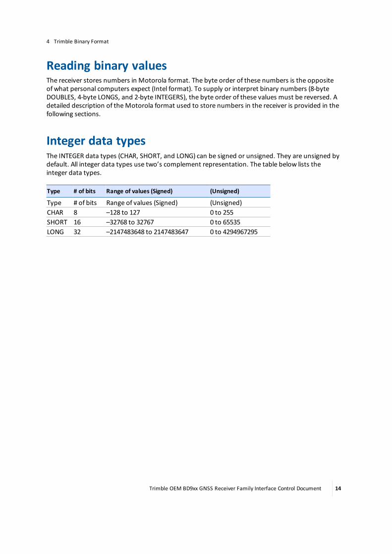
Reading binary valuesThe receiver stores numbers in Motorola format. The byte order of these numbers is the oppositeof what personal computers expect (Intel format). To supply or interpret binary numbers (8-byteDOUBLES, 4-byte LONGS, and 2-byte INTEGERS), the byte order of these values must be reversed. Adetailed description of theMotorola format used to store numbers in the receiver is provided in thefollowing sections.
Integer data typesThe INTEGER data types (CHAR, SHORT, and LONG) can be signed or unsigned. They are unsigned bydefault. All integer data types use two’s complement representation. The table below lists theinteger data types.
Type # of bits Range of values (Signed) (Unsigned)
Type # of bits Range of values (Signed) (Unsigned)CHAR 8 –128 to 127 0 to 255SHORT 16 –32768 to 32767 0 to 65535LONG 32 –2147483648 to 2147483647 0 to 4294967295
Trimble OEM BD9xx GNSS Receiver Family Interface Control Document 14

4 Trimble Binary Format
Floating point data typesFloating-point data types are stored in the IEEE SINGLE and DOUBLE precision formats. Both formatshave a sign bit field, an exponent field, and a fraction field. The fields represent floating-pointnumbers in the following manner:
Floating-Point Number = <sign> 1.<fraction field> x 2 (<exponent field> - bias)
l Sign bit field
The sign bit field is themost significant bit of the floating-point number. The sign bit is 0 forpositive numbers and 1 for negative numbers.
l Fraction field
The fraction field contains the fractional part of a normalized number. Normalized numbers aregreater than or equal to 1 and less than 2. Since all normalized numbers are of the form1.XXXXXXXX, the 1 becomes implicit and is not stored in memory. The bits in the fraction fieldare the bits to the right of the binary point, and they represent negative powers of 2.
For example:
0.011 (binary) = 2-2 + 2-3 = 0.25 + 0.125 = 0.375
l Exponent field
The exponent field contains a biased exponent; that is, a constant bias is subtracted from thenumber in the exponent field to yield the actual exponent. (The bias makes negative exponentspossible.)
If both the exponent field and the fraction field are zero, the floating-point number is zero.
l NaN
ANaN (Not a Number) is a special value that is used when the result of an operation isundefined. For example, dividing a number by zero results in a NaN.
FLOAT data typeThe FLOAT data type is stored in the IEEE single-precision format which is 32 bits long. Themostsignificant bit is the sign bit, the next 8most significant bits are the exponent field, and theremaining 23 bits are the fraction field. The bias of the exponent is 127. The range of single-precisionformat values is from 1.18 × 10–38 to 3.4 × 1038. The floating-point number is precise to 6 decimaldigits.
Trimble OEM BD9xx GNSS Receiver Family Interface Control Document 15
4 Trimble Binary Format
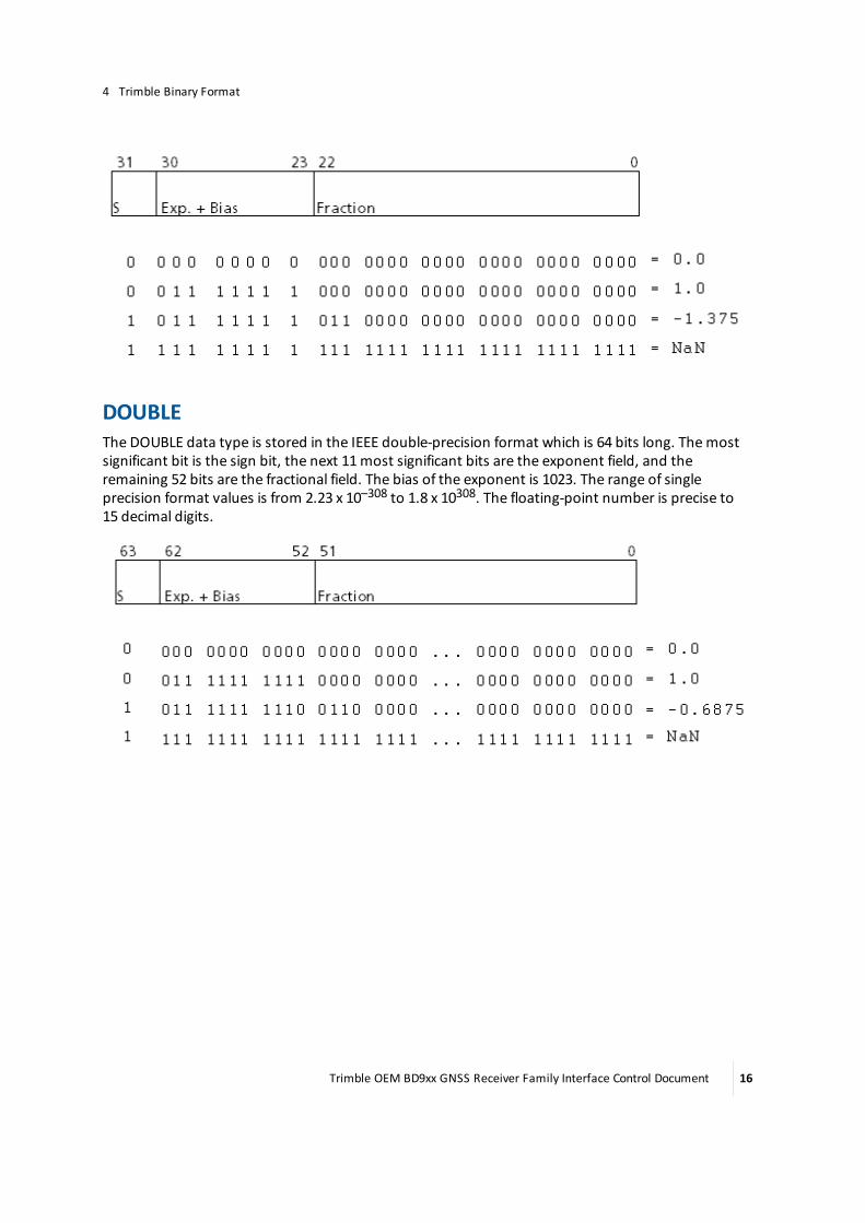
DOUBLEThe DOUBLE data type is stored in the IEEE double-precision format which is 64 bits long. Themostsignificant bit is the sign bit, the next 11most significant bits are the exponent field, and theremaining 52 bits are the fractional field. The bias of the exponent is 1023. The range of singleprecision format values is from 2.23 x 10–308 to 1.8 x 10308. The floating-point number is precise to15 decimal digits.
Trimble OEM BD9xx GNSS Receiver Family Interface Control Document 16
Command and Report Packets
In this chapter:
n Command packet and report packetsummary
n Receiver and antenna information packets
n Position, measurements, and satelliteinformation packets
n Application file packets
n Display screen and software interfacepackets
n Miscellaneous receiver control packets
This chapter documents the Command andReport packets.
Trimble OEM BD9xx GNSS Receiver Family Interface Control Document 17
5

Command packet and report packet summaryCategory Packets See...
Receiver and antenna informationpackets
Command 06h, GETSERIAL page 19Response 07h, RETSERIAL page 19Command 4Ah, GETOPT page 21Response 4Bh, RETOPT page 22
Position, measurements, and satelliteinformation packets
Command 54h GETSVDATA page 25Response 55h, RETSVDATA (SatelliteInformation Reports)
page 28
Command 56h, GETRAW (Position or real-timesurvey data request)
page 46
Response 57h, RAWDATA (Position or real-timesurvey data report)
page 48
Application file packets Command 64h, APPFILE (Application file record) page 65Command 65h, GETAPPFILE (Application filerequest)
page 92
Command 66h, GETAFDIR (Application filedirectory listing)
page 94
Response 67h, RETAFDIR (Directory listingreport)
page 95
Command 68h, DELAPPFILE (Delete applicationfile data)
page 97
Command 6Dh, ACTAPPFILE (Activateapplication file)
page 98
Display screen and software interfacepackets
Command 81h, KEYSIM (Key simulator) page 99Command 82h, SCRDUMP (Screen dumprequest)
page 101
Response 82h, SCRDUMP (Screen dump) page 102Miscellaneous receiver control packets Command/ResponseAEh, Ethernet
configurationpage 103
Command 6Fh, BREAKREQ page 107Response 6Eh, BREAKRET (Break sequencereturn)
page 108
Command 58h, RESETRCVR (Reset Receiver) page 112
Trimble OEM BD9xx GNSS Receiver Family Interface Control Document 18

Receiver and antenna information packets
Command 06h, GETSERIALCommand Packet 06h requests receiver and antenna information. The receiver responds by sendingthe data in the Report Packet 07h.
All data in the packet flows from the data collector to the receiver.
Byte Item Type Value Meaning
0 STX 1 (Char) 02h Start transmission1 STATUS 1 (Char) See Receiver status byte, page 11 Receiver status code2 PACKET TYPE 1 (Char) 06h Command Packet 06h3 LENGTH 1 (Char) 00h Data byte count4 CHECKSUM 1 (Char) See Packet structure, page 11 Checksum value5 ETX 1 (Char) 03h End transmission
Response 07h, RETSERIALReport Packet 07h is sent in response to the Command Packet 06h. The report returns the receiverand antenna serial number, antenna type, software processor versions, and the number of receiverchannels.
All data in the packet flows from the receiver to the data collector.
Byte Item Type Value Meaning
0 STX 1 (Char) 02h Start transmission.1 STATUS 1 (Char) Receiver status code. See Receiver status
byte, page 11.2 PACKET TYPE 1 (Char) 07h3 LENGTH 1 (Char) ??h Bytes of data after this byte (excluding
checksum and ETX).4–11 RECEIVER SERIAL # 8 (Chars) ASCII
textReceiver serial number.
Note – On newer receivers such as the BD920,this field gives the lowest (least significant) 8characters of the serial number and so the LONGSERIAL NUMBER field should be used instead.
12–19 RECEIVER TYPE 8 (Chars) "BD9xx" Space padding string with three spaces forthe BD9xx.
20–24 NAV PROCESSVERSION
5 (Chars) ASCIItext
Version number for firmware.
25–29 SIG PROCESSVERSION
5 (Chars)
30–34 BOOT ROMVERSION
5 (Chars)
Trimble OEM BD9xx GNSS Receiver Family Interface Control Document 19

Byte Item Type Value Meaning
35–42 ANTENNA SERIAL # 8 (Chars)43–44 ANTENNA TYPE 2 (Chars) “E” is unknown external; “KS” is Zephyr
model; “GS” is Zephyr Geodetic.45–46 # CHANNELS 2 (Chars) Total number of GPS receive channels,
including L1 and L2.47–48 # CHANNELS L1 2 (Chars) Number of channels only on L1.49 - 58 LONG SERIAL
NUMBER10 (Chars) This is the serial number that should be used
instead of Receiver Serial.59 - 89 LOCAL LONG ANT
SERIAL31 (Chars) Not Applicable
90 - 120 BASE LONG ANTSERIAL
31 (Chars) Not Applicable
121 - 151 BASE NGS ANTDESCRIPTOR
31 (Chars) Not Applicable
152-153 # USABLECHANNELS
2 (Bytes) Maximum number of usable channels withcurrent configuration.
154-155 # PHYSICALCHANNELS
2 (Bytes) Total number of hardware channels present.
156 # SIMULTANEOUSCHANNELS
1 (Byte) Number of satellites that the receiver cantrack at one time.
157-161 Antenna INIversion
5 (Chars) ASCIItext
Version number from the antenna.ini filethat is currently loaded into the receiver.
162 CHECKSUM 1 (Char) ??h Checksum value. See Packet structure, page11.
163 ETX 1 (Char) 03h End transmission.
Where,
Receiver Serial is an 8-character-maximum serial number. On newer receivers with longer serialnumbers this field gives the lowest (least significant) 8 characters of the serial number, but the LongSerial Number field should be used instead.
Trimble OEM BD9xx GNSS Receiver Family Interface Control Document 20
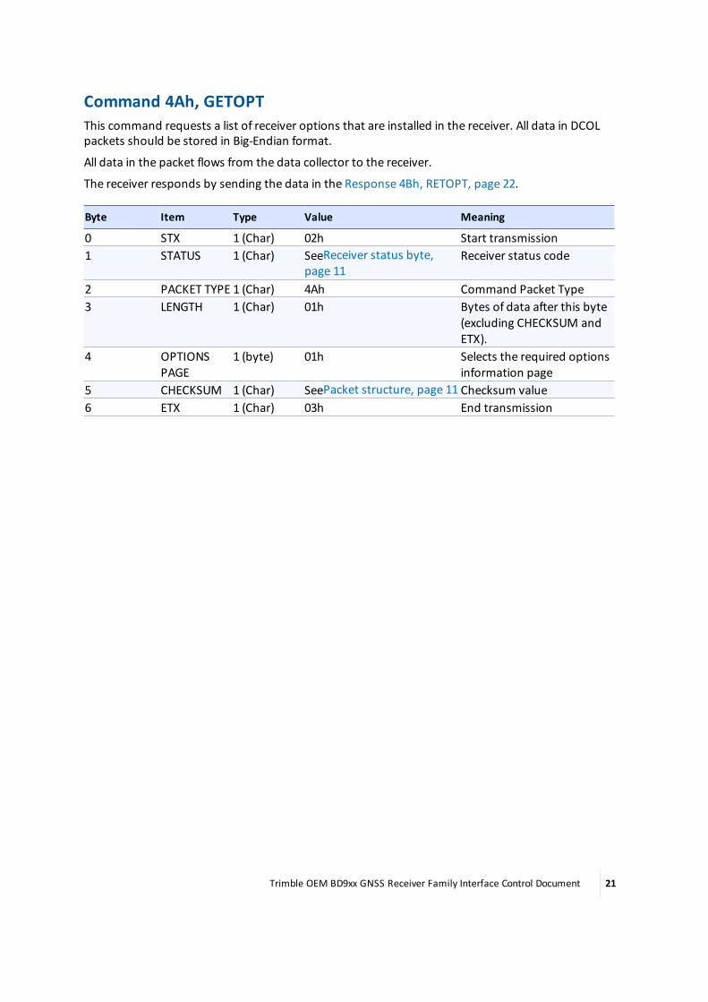
Command 4Ah, GETOPTThis command requests a list of receiver options that are installed in the receiver. All data in DCOLpackets should be stored in Big-Endian format.
All data in the packet flows from the data collector to the receiver.
The receiver responds by sending the data in the Response 4Bh, RETOPT, page 22.
Byte Item Type Value Meaning
0 STX 1 (Char) 02h Start transmission1 STATUS 1 (Char) SeeReceiver status byte,
page 11Receiver status code
2 PACKET TYPE 1 (Char) 4Ah Command Packet Type3 LENGTH 1 (Char) 01h Bytes of data after this byte
(excluding CHECKSUM andETX).
4 OPTIONSPAGE
1 (byte) 01h Selects the required optionsinformation page
5 CHECKSUM 1 (Char) SeePacket structure, page 11 Checksum value6 ETX 1 (Char) 03h End transmission
Trimble OEM BD9xx GNSS Receiver Family Interface Control Document 21

Response 4Bh, RETOPTThis packet response returns all the options installed in the receiver. These options can also be seenin the web interface (Receiver Status / Receiver Options).
All data in the packet flows from the receiver to the data collector.
Report Packet 4Bh is sent in response to the Command 4Ah, GETOPT, page 21.
Byte Item Type Value Meaning
0 STX 1 (Char) 02h Start transmission.1 STATUS 1 (Char) 00h Receiver status code. See Receiver status byte,
page 11.2 PACKET
TYPE1 (Char) 4Bh Command Packet Type.
3 LENGTH 1 (Char) 22h (34h or??h)
Bytes of data after this byte (excludingchecksum and ETX).
4 PAGENUMBER
1 (byte) 5Bh Elevation Mask / Page 91 = page 1 (page 0, 1, or2)
----- If page = 1 (page 0, 1, and 2 available) -----5 Number of
PagesSupported
1 (byte)
6–7 RESERVED 2 (short)8–9 RESERVED 2 (short)10–11 RESERVED 2 (short)12–15 OPTION
BLOCK BITS0–31 (LSB isbit 0)
4 (int) OPTION BLOCK BITS 0–95 best processed as 3unsigned long integers. For example, todetermine if the GLONASS option is installed inreceiver, check if bit #32 is enabled (1). GLONASSenable bit (data byte 16 counting from 1 pagenumber) and least significant bit (0) of that byte.The currently defined bits are given below thistable.
16–19 OPTIONBLOCK BITS32–63 (LSBis bit 32)
4 (int)
20–23 OPTIONBLOCK BITS64–95 (LSBis bit 64)
4 (int)
24–25 RESERVED 2 (short)26–28 RESERVED 3 (bytes)29–31 RESERVED 3 (bytes)32 RESERVED 1 (byte)33 RESERVED 1 (byte)34 RESERVED 1 (byte)35 RESERVED 1 (byte)
Trimble OEM BD9xx GNSS Receiver Family Interface Control Document 22

Byte Item Type Value Meaning
36–37 RESERVED 2 (short)38 CHECKSUM1 (Char) ??h Checksum value. See Packet structure, page 11.39 ETX 1 (Char) 03h End transmission.
Where,
Option block bits are defined as follows: bit = 1 (enabled), bit = 0 (disabled)
bit 0: CMR inputs
bit 1: CMR outputs
bit 2: RTCM inputs
bit 3: RTCM outputs
bit 4: N/A
bit 5: N/A
bit 6: N/A
bit 7: Binary outputs (RT17)
bit 8: Moving base
bit 9: 10Hz measurements
bit 10: 20Hz measurements
bit 11: N/A
bit 12: N/A
bit 13: N/A
bit 14: Event markers
bit 15: N/A
bit 16: Force RTK float position
bit 17: N/A
bit 18: N/A
bit 19: Disable L2 outputs
bit 20: N/A
bit 21: L2CS support
bit 22–25: N/A
bit 26: Disable NMEA outputs
bit 27: Disable VRS
bit 28: RTCM DGPS only
bit 29: GPS L5 signal processing available
bit 30: Support OmniSTAR and XP/HP connection
bit 31: Disables the use of Everest multipath mitigation
bit 32: GLONASS enabled
Trimble OEM BD9xx GNSS Receiver Family Interface Control Document 23

bit 33: EnableWeb UI support
bits 34–46: N/A
bit 37: Heading mode only
bit 40: Force float position with static CMR
bit 41: Only output scrambled CMR corrections
bit 42: N/A
bit 43: N/A
bit 44: Disable SBAS
bit 45: Disable FTP
bit 46: N/A
bit 47: Disable CMRx output
bit 48: Disable CMRx input
bit 49: N/A
bit 50: N/A
bit 51: N/A
bit 52: BeiDou enabled
bit 53: N/A
bit 54: N/A
bit 55: Galileo enabled
bit 56: N/A
bit 57: Enable scramble CMRx
bit 58: N/A
bit 59: N/A
bit 60: Enable scramble CMRx output
bit 62: Disable vector antenna
bit 63: N/A
bit 64: N/A
bit 65: N/A
bit 66: QZSS enabled
bit 67: N/A
bit 68: L1 RTK support enabled
bits 70–95:
Trimble OEM BD9xx GNSS Receiver Family Interface Control Document 24

Position, measurements, and satellite informationpackets
Command 54h, GETSVDATACommand Packet 54h requests satellite information. The request may be for an array of flagsshowing the availability of satellite information such as an ephemeris or almanac. In addition,satellites may be enabled or disabled with this command packet.
Note – The normal reply to Command Packet 54h is usually Report Packet 55h. However, a NAK isreturned if the SV PRN is out of range (except for SV FLAGS), if the DATA SWITCH parameter is out ofrange, or if the requested data is not available for the designated SV.
All data in the packet flows from the data collector to the receiver.
Byte Item Type Value Meaning
0 STX 1 (Char) 02h Start transmission1 STATUS 1 (Char) 00h Receiver status code2 PACKET TYPE 1 (Char) 54h Command Packet
Type3 LENGTH 1 (Char) 03h, 04h Data byte count4 SUBTYPE 1 (byte) See below See below
----- DATA RECORDS 0—16 and 21–22-----
Data from one of the records that are encoded in type 55h records, as indicated by byte #4Subtype. Bytes 5 & 6 below; PRN& Flags, respectively; will be sent:
0: SV flags indicating Tracking, Ephemeris and Almanac, Enable/Disable state. (Deprecated. Usesubtype 20.)
1: GPS Ephemeris
2: GPS Almanac
3: ION / UTC Data
4: Disable Satellite (Deprecated. Use subtype 20)
5: Enable Satellite (Deprecated. Use subtype 20)
7: Extended GPS Almanac (includes clock parameters)
8: GLONASS Almanac
9: GLONASS Ephemeris
11: Galileo Ephemeris
12: Galileo Almanac
14: QZSS Ephemeris
16: QZSS Almanac
21: BeiDou Ephemeris
22: BeiDou Almanac
Trimble OEM BD9xx GNSS Receiver Family Interface Control Document 25

Byte Item Type Value Meaning
5 SV PRNNUMBER 1 (byte) See below See below6 FLAGS 1 (byte) See below See below
----- DATA RECORD 20-----
Data from one of the records that are encoded in type 55h records, as indicated by byte #4Subtype. Bytes 5, 6, & 7 below; PRN, SAT TYPE, &MODE, respectively; will be sent:
20: SV Enable/Disable/Ignore Health Controls5 SV PRNNUMBER 1 (byte) See below See below6 SAT TYPE 1 (byte) See below See below7 MODE 1 (byte) See below See below
CHECKSUM 1 (Char) See Packet structure,page 11
Checksum value
ETX 1 (Char) 03h End transmission
Where,
SV PRN Number: Satellite number for which ephemeris/almanac is required or to be enabled/disabled. Ignored if SV flags or ION / UTC data is requested.
1–32 : GPS satellites
52–75: (GLONASS SV 1–24). FLAGS bit 1must be set to 0 for subtypes 4 and 5.
Galileo SV Range: 1–36. FLAGS bit 1must be set to 0 for subtypes 4 and 5.
QZSS SV Range: 193 - 198. FLAGS bit 1must be set to 0 for subtypes 4 and 5.
BeiDou SV Range: 1–30. FLAGS bit 1must be set to 0 for subtypes 4 and 5.
FLAGS: Bitmapped field having the following values:
Bit 0 set: Return GLONASS Flags appended to the GPS FLAGS replies (subtypes 0, 4, 5)
Bit 1 Set: Return Galileo and GLONASS Flags appended to the GPS FLAGS replies(subtypes 0, 4, 5). SV being controlled is Galileo, not GPS or GLONASS (subtypes 4, 5).
Bits 2 and 3 Specify the source of Galileo Ephemeris or QZSS Ephemeris:
For Galileo:
b3:b2 = 00 => E1B
b3:b2 = 01 => E5B
b3:b2 = 10 => E5A
For QZSS:
b3:b2 = 00 => L1CA
b3:b2 = 01 => L1C
b3:b2 = 10 => L2C
b3:b2 = 11 => L5
Trimble OEM BD9xx GNSS Receiver Family Interface Control Document 26

Bit4 Set: Return QZSS, Galileo and GLONASS flags appendedto the GPS FLAGS replies (subtypes 0, 4, 5). SV beingcontrolled is QZSS, not GPS, GLONASS or Galileo.
SAT TYPE: Subtype 20 only. Specifies the Satellite System for the PRNwhich is being configured.
0: GPS: 1–32
1: SBAS (WAAS, EGNOS, MSAS etc): 1–39 (PRN 120–158)
2: GLONASS: 1–24
3: Galileo: 1–36
4: QZSS: 1–5 (PRN 193-197)
7: BeiDou: 1–30
MODE: Subtype 20 only.
0: Return SV flags for SAT TYPE
1: Disable SV
2: Enable SV
3: Ignore Health SV
Only Mode = 0 is valid for SBAS.
The reply for this command will be a RETSVDATA packet, or a NAK if the request failed.
Enable/Disable satellite (subtype 20) always returns RETSVDATA (subtype 20) as if SV Flags wererequested
Trimble OEM BD9xx GNSS Receiver Family Interface Control Document 27

Response 55h, RETSVDATA (Satellite information reports)Report Packet 55h is sent in response to Command Packet 54h. The report includes either theephemeris or almanac information for a specific satellite, or ION/UTC data, the Enabled/Disabledstate and Heed/Ignore Health state of all satellites, or the condition of satellite status flags for onesatellite or all satellites.
All data in the packet flows from the receiver to the data collector.
Byte Item Type Value Meaning
0 STX 1 (Char) 02h Start Transmission1 STATUS 1 (Char) ??h (see
below)Receiver Status Code
2 PACKETTYPE
1 (Char) 55h Response Packet Type
3 LENGTH 1 (Char) ??h Bytes of data after this byte (excluding checksumand ETX)
4 Subtype 1 byte Refersubtypevaluesbelow
Each subtype data field shown in the followingtables will be output based on the 54h commandsent, as shown above.
----- DATA RECORDS 0—22-----
Data from one of the records that are encoded in type 55h records, as indicated by byte #4Subtype.
0: SV flags indicating tracking, ephemeris, almanac, and enabled status (Deprecated. Use subtype20.)
1: GPS Ephemeris
2: GPS Almanac
3: ION / UTC Data
4: Disable Satellite (Deprecated. Use subtype 20.)
5: Enable Satellite (Deprecated. Use subtype 20.)
7: Extended GPS Almanac (includes clock parameters)
8: GLONASS Almanac
9: GLONASS Ephemeris
11: Galileo Ephemeris
12: Galileo Almanac
14: QZSS Ephemeris
16: QZSS Almanac
20: SV Flags
21: BeiDou Ephemeris
22: BeiDou Almanac
Trimble OEM BD9xx GNSS Receiver Family Interface Control Document 28

Byte Item Type Value Meaning
Lastsubtypebyte + 1
CHECKSUM Char ??h Checksum Value
Lastsubtypebyte + 2
ETX Char 03h End Transmission
Only the satellite information, requested by Command Packet 54h, is sent in the report packet. As aresult, several forms of the Report Packet 55h can be requested.
Returns a NAK if the GETSVDATA request meets one of the following criteria:
l SV PRN is out of range (except for SV flags)
l Data Switch is out of range
l Data is not available for the requested SV
Trimble OEM BD9xx GNSS Receiver Family Interface Control Document 29
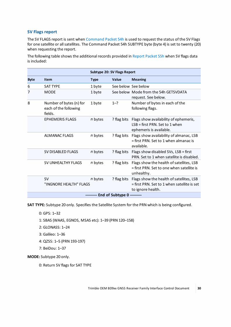
SV Flags reportThe SV FLAGS report is sent when Command Packet 54h is used to request the status of the SV Flagsfor one satellite or all satellites. The Command Packet 54h SUBTYPE byte (byte 4) is set to twenty (20)when requesting the report.
The following table shows the additional records provided in Report Packet 55h when SV flags datais included:
Subtype 20: SV Flags Report
Byte Item Type Value Meaning
6 SAT TYPE 1 byte See below See below7 MODE 1 byte See below Mode from the 54h GETSVDATA
request. See below.8 Number of bytes (n) for
each of the followingfields.
1 byte 1–? Number of bytes in each of thefollowing flags.
EPHEMERIS FLAGS n bytes ? flag bits Flags show availability of ephemeris,LSB = first PRN. Set to 1whenephemeris is available.
ALMANAC FLAGS n bytes ? flag bits Flags show availability of almanac, LSB= first PRN. Set to 1when almanac isavailable.
SV DISABLED FLAGS n bytes ? flag bits Flags show disabled SVs, LSB = firstPRN. Set to 1when satellite is disabled.
SV UNHEALTHY FLAGS n bytes ? flag bits Flags show the health of satellites, LSB= first PRN. Set to one when satellite isunhealthy.
SV"INGNORE HEALTH" FLAGS
n bytes ? flag bits Flags show the health of satellites, LSB= first PRN. Set to 1when satellite is setto ignore health.
---------- End of Subtype 0 ----------
SAT TYPE: Subtype 20 only. Specifies the Satellite System for the PRNwhich is being configured.
0: GPS: 1–32
1: SBAS (WAAS, EGNOS, MSAS etc): 1–39 (PRN 120–158)
2: GLONASS: 1–24
3: Galileo: 1–36
4: QZSS: 1–5 (PRN 193-197)
7: BeiDou: 1–37
MODE: Subtype 20 only.
0: Return SV flags for SAT TYPE
Trimble OEM BD9xx GNSS Receiver Family Interface Control Document 30

1: Disable SV
2: Enable SV
3: Ignore Health SV
4: QZSS: 1-5 (PRN 193-197)
7: BeiDou: 1-37
Only Mode = 0 is valid for SBAS.
The Command Packet 54h subtype 0message is depreciated and subtype 20 should be used. Forreference, the subtype 0was structured as follows:
Subtype 0: SV Flags Report
Byte Item Type Value Meaning
6–9 EPHEMERISFLAGS
4 (doubleword)
32 flagbits
For all satellites, the flags show availability ofephemeris data when set to one where bit #0corresponds to PRN 1.
10–13 ALMANACFLAGS
4 (doubleword)
32 flagbits
For all satellites, the flags show availability of almanacdata when set to 1.
14–17 SV DISABLEDFLAGS
4 (doubleword)
32 flagbits
Flags show Enabled or Disabled status of all satellites.Set to 1when satellite is disabled.
18–21 SVUNHEALTHYFLAGS
4 (doubleword)
32 flagbits
Flags show the health of satellites. Set to 1whensatellite is unhealthy.
22–25 TRACKING L1FLAGS
4 (doubleword)
32 flagbits
Flags show satellites tracked on L1when set to one.
26–29 TRACKING L2FLAGS
4 (doubleword)
32 flagbits
Flags show satellites tracked on L2when set to one.
30–33 Y-CODEFLAGS
4 (doubleword)
32 flagbits
Flags show satellites with Anti-Spoofing turned onwhen set to one.
34–37 P-CODE ONL1 FLAGS
4 (doubleword)
32 flagbits
Flags show satellites which are tracking P-code on L1.Flags are not set for satellites not tracked on L1.
38–41 RESERVED 4 (doubleword)
32 flagbits
Reserved (set to 0).
42–45 RESERVED 4 (doubleword)
32 flagbits
Reserved (set to 0).
46–49 RESERVED 4 (doubleword)
32 flagbits
Reserved (set to 0).
50–53 RESERVED 4 (doubleword)
32 flagbits
Reserved (set to 0).
---------- End of Subtype 0 ----------
Trimble OEM BD9xx GNSS Receiver Family Interface Control Document 31

GPS ephemeris reportThe ephemeris report is sent when Command Packet 54h is used to request the ephemeris for onesatellite or all satellites. The GETSVDATA SUBTYPE byte (byte 4) is set to one (1) to request the report.The first following table shows the additional records provided in Report Packet 55h whenephemeris data is included.
The ephemeris data follows the standard defined by GPS ICD-200 except for CUC, CUS, CIS, and CIC.These values must bemultiplied by π to become the units specified in the GPS ICD-200 document.The ephemeris flags are described in the second following table.
Subtype 1: GPS ephemeris data
Byte Item Type Value Meaning
6–7 EPHEMERIS WEEK # 2 (short) GPS ICD-200 Ephemeris Week Number.8–9 IODC 2 (short) GPS ICD-20010 RESERVED 1 (byte) GPS ICD-20011 IODE 1 (byte) GPS ICD-20012–15 TOW 4 (long) GPS ICD-20016–19 TOC 4 (long) GPS ICD-20020–23 TOE 4 (long) GPS ICD-20024–31 TGD 8 (double) GPS ICD-20032–39 AF2 8 (double) GPS ICD-20040–47 AF1 8 (double) GPS ICD-20048–55 AF0 8 (double) GPS ICD-20056–63 CRS 8 (double) GPS ICD-20064–71 DELTAN 8 (double) GPS ICD-20072–79 M SUB 0 8 (double) GPS ICD-20080–87 CUC 8 (double) Multiply by π to obtain ICD units.88–95 ECCENTRICITY 8 (double) GPS ICD-20096–103 CUS 8 (double) Multiply by π to obtain ICD units.104–111 SQRT A 8 (double) GPS ICD-200112–119 CIC 8 (double) Multiply by π to obtain ICD units.120–127 OMEGA SUB 0 8 (double) GPS ICD-200128–135 CIS 8 (double) Multiply by π to obtain ICD units.136–143 I SUB 0 8 (double) GPS ICD-200144–151 CRC 8 (double) GPS ICD-200152–159 OMEGA 8 (double) GPS ICD-200160–167 OMEGADOT 8 (double) GPS ICD-200168–175 I DOT 8 (double) GPS ICD-200176–179 FLAGS 4 (double
word)GPS ICD-200
---------- End of Subtype 1 ----------
Trimble OEM BD9xx GNSS Receiver Family Interface Control Document 32
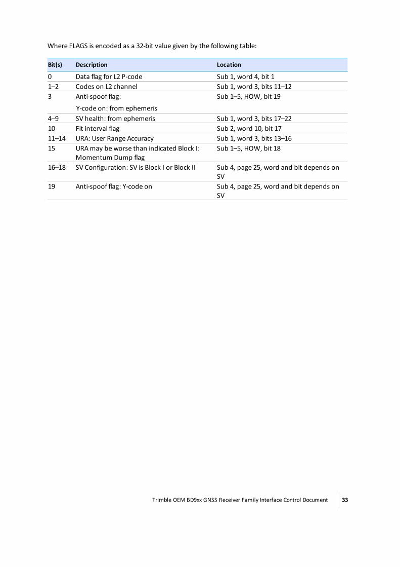
Where FLAGS is encoded as a 32-bit value given by the following table:
Bit(s) Description Location
0 Data flag for L2 P-code Sub 1, word 4, bit 11–2 Codes on L2 channel Sub 1, word 3, bits 11–123 Anti-spoof flag:
Y-code on: from ephemeris
Sub 1–5, HOW, bit 19
4–9 SV health: from ephemeris Sub 1, word 3, bits 17–2210 Fit interval flag Sub 2, word 10, bit 1711–14 URA: User Range Accuracy Sub 1, word 3, bits 13–1615 URAmay be worse than indicated Block I:
Momentum Dump flagSub 1–5, HOW, bit 18
16–18 SV Configuration: SV is Block I or Block II Sub 4, page 25, word and bit depends onSV
19 Anti-spoof flag: Y-code on Sub 4, page 25, word and bit depends onSV
Trimble OEM BD9xx GNSS Receiver Family Interface Control Document 33
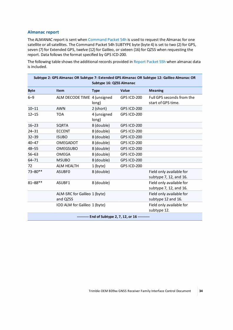
Almanac reportThe ALMANAC report is sent when Command Packet 54h is used to request the Almanac for onesatellite or all satellites. The Command Packet 54h SUBTYPE byte (byte 4) is set to two (2) for GPS,seven (7) for Extended GPS, twelve (12) for Galileo, or sixteen (16) for QZSS when requesting thereport. Data follows the format specified by GPS ICD-200.
The following table shows the additional records provided in Report Packet 55h when almanac datais included.
Subtype 2: GPS Almanac OR Subtype 7: Extended GPS Almanac OR Subtype 12: Galileo Almanac ORSubtype 16: QZSS Almanac
Byte Item Type Value Meaning
6–9 ALM DECODE TIME 4 (unsignedlong)
GPS ICD-200 Full GPS seconds from thestart of GPS time.
10–11 AWN 2 (short) GPS ICD-20012–15 TOA 4 (unsigned
long)GPS ICD-200
16–23 SQRTA 8 (double) GPS ICD-20024–31 ECCENT 8 (double) GPS ICD-20032–39 ISUBO 8 (double) GPS ICD-20040–47 OMEGADOT 8 (double) GPS ICD-20048–55 OMEGSUBO 8 (double) GPS ICD-20056–63 OMEGA 8 (double) GPS ICD-20064–71 MSUBO 8 (double) GPS ICD-20072 ALM HEALTH 1 (byte) GPS ICD-20073–80** ASUBF0 8 (double) Field only available for
subtype 7, 12, and 16.81–88** ASUBF1 8 (double) Field only available for
subtype 7, 12, and 16.ALM-SRC for Galileoand QZSS
1 (byte) Field only available forsubtype 12 and 16.
IOD ALM for Galileo 1 (byte) Field only available forsubtype 12.
---------- End of Subtype 2, 7, 12, or 16 ----------
Trimble OEM BD9xx GNSS Receiver Family Interface Control Document 34
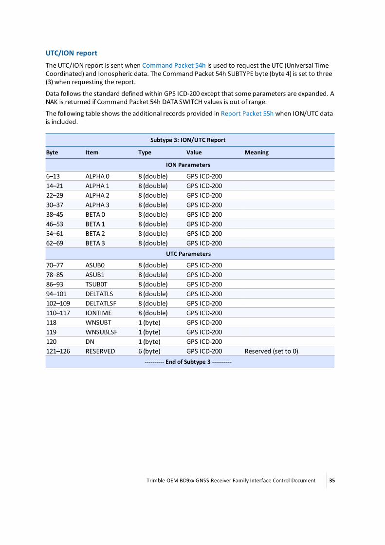
UTC/ION reportThe UTC/ION report is sent when Command Packet 54h is used to request the UTC (Universal TimeCoordinated) and Ionospheric data. The Command Packet 54h SUBTYPE byte (byte 4) is set to three(3) when requesting the report.
Data follows the standard defined within GPS ICD-200 except that some parameters are expanded. ANAK is returned if Command Packet 54h DATA SWITCH values is out of range.
The following table shows the additional records provided in Report Packet 55h when ION/UTC datais included.
Subtype 3: ION/UTC Report
Byte Item Type Value Meaning
ION Parameters
6–13 ALPHA 0 8 (double) GPS ICD-20014–21 ALPHA 1 8 (double) GPS ICD-20022–29 ALPHA 2 8 (double) GPS ICD-20030–37 ALPHA 3 8 (double) GPS ICD-20038–45 BETA 0 8 (double) GPS ICD-20046–53 BETA 1 8 (double) GPS ICD-20054–61 BETA 2 8 (double) GPS ICD-20062–69 BETA 3 8 (double) GPS ICD-200
UTC Parameters
70–77 ASUB0 8 (double) GPS ICD-20078–85 ASUB1 8 (double) GPS ICD-20086–93 TSUB0T 8 (double) GPS ICD-20094–101 DELTATLS 8 (double) GPS ICD-200102–109 DELTATLSF 8 (double) GPS ICD-200110–117 IONTIME 8 (double) GPS ICD-200118 WNSUBT 1 (byte) GPS ICD-200119 WNSUBLSF 1 (byte) GPS ICD-200120 DN 1 (byte) GPS ICD-200121–126 RESERVED 6 (byte) GPS ICD-200 Reserved (set to 0).
---------- End of Subtype 3 ----------
Trimble OEM BD9xx GNSS Receiver Family Interface Control Document 35

GLONASS almanac reportThe GLONASS ALMANAC report is sent when Command Packet 54h is used to request the Almanacfor one GLONASS satellite or all GLONASS satellites. The Command Packet 54h SUBTYPE byte (byte 4)is set to eight (8) when requesting the report.
The following table shows the additional records provided in Report Packet 55h when GLONASSalmanac data is included.
Subtype 8: GLONASS Almanac
Byte Item Type Value Meaning
6–7 DAY NUMBER 2 (word) Day number within the current 4-yearcycle.
8 FDMANUMBER 1 (byte) -7 to 13 (signed char) FDMA channel number9–16 ECCENTRICITY 8 (double)17–24 ARG OF PERIGEE 8 (double) radians Argument of Perigee25–32 ORBIT PERIOD 8 (double) seconds33–40 ORBITAL PERIOD
CORRECTION8 (double)
41–48 LONG FIRST ASCENDINGNODE
8 (double) Longitude of the first ascending node
49–56 TIME ASCENDING NODE 8 (double)57–64 INCLINATION 8 (double) radians Inclination is in65–72 A0 8 (double) seconds Satellite clock offset from system time73 HEALTH 1 (byte)
---------- End of Subtype 8 ----------
Trimble OEM BD9xx GNSS Receiver Family Interface Control Document 36

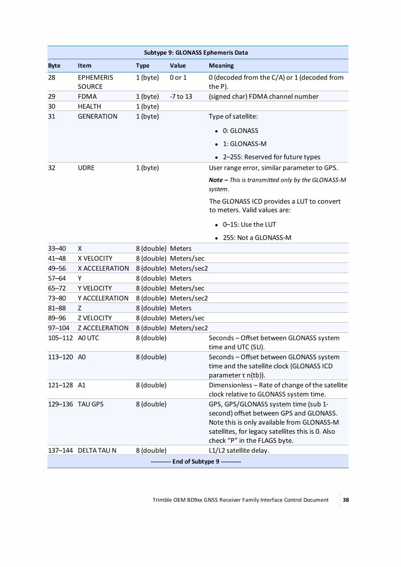
GLONASS ephemeris reportThe GLONASS ephemeris report is sent when Command Packet 54h is used to request theEphemeris for one GLONASS satellite or all GLONASS satellites. The GETSVDATA SUBTYPE byte (byte4) is set to nine (9) to request the report. The following table shows the additional records providedin Report Packet 55h when GLONASS ephemeris data is included.
The ephemeris data follows the standard defined by the GLONASS ICD.
Subtype 9: GLONASS Ephemeris Data
Byte Item Type Value Meaning
6–7 GPS WEEK EPHVALID REF TIME
2 (word) GPS Week number of the ephemeris validitytime.
8–11 GPS TIME EPHVALID REF TIME
4 (long) GPS Time ofWeek (seconds) of the ephemerisvalidity time.
12–13 GPS WEEK EPHDECODE REF TIME
2 (word) GPS Week number of the start time of themost recent GLONASS frame in which thecurrent ephemeris has been decoded.
14–17 GPS TIME EPHDECODE REF TIME
4 (long) GPS Time ofWeek (seconds) of the start timeof themost recent GLONASS frame in whichthe current ephemeris has been decoded.
18–19 GLONASS DAYNUMBER
2 (word) Days since the last leap year (rolls over every 4years).
20 REF TIME OFEPHEMERIS
1 (byte) Time of validity of the ephemeris in units of900 seconds (tb in theGLONASS ICD).
21 LEAP SECONDS 1 (byte) GPS System time to UTC integer seconds(from GPS).
22 FLAGS 1 (byte) Bitmapped field of flags described in theGLONASS ICD:
l Bit 0,1: P (if SV is GLONASS-M, 0otherwise)
l Bit 2,3: P1 (encode the time intervalbetween the adjacent values of tb:(00,01,10,11)map to (0,30,45,60)minutesrespectively)
l Bit 4: P2
l Bit 5: P3
l Bit 6: P4 (if SV is GLONASS-M, 0otherwise)
l Bit 7: Change bit23–26 FRAME START
TIME4 (long) Time into the current date that this data was
first decoded (tk in the GLONASS ICD).27 AGE OF DATA 1 (byte) days
Trimble OEM BD9xx GNSS Receiver Family Interface Control Document 37
Subtype 9: GLONASS Ephemeris Data
Byte Item Type Value Meaning
28 EPHEMERISSOURCE
1 (byte) 0 or 1 0 (decoded from the C/A) or 1 (decoded fromthe P).
29 FDMA 1 (byte) -7 to 13 (signed char) FDMA channel number30 HEALTH 1 (byte)31 GENERATION 1 (byte) Type of satellite:
l 0: GLONASS
l 1: GLONASS-M
l 2–255: Reserved for future types32 UDRE 1 (byte) User range error, similar parameter to GPS.
Note – This is transmitted only by the GLONASS-Msystem.
The GLONASS ICD provides a LUT to convertto meters. Valid values are:
l 0–15: Use the LUT
l 255: Not a GLONASS-M33–40 X 8 (double) Meters41–48 X VELOCITY 8 (double) Meters/sec49–56 X ACCELERATION 8 (double) Meters/sec257–64 Y 8 (double) Meters65–72 Y VELOCITY 8 (double) Meters/sec73–80 Y ACCELERATION 8 (double) Meters/sec281–88 Z 8 (double) Meters89–96 Z VELOCITY 8 (double) Meters/sec97–104 Z ACCELERATION 8 (double) Meters/sec2105–112 A0 UTC 8 (double) Seconds – Offset between GLONASS system
time and UTC (SU).113–120 A0 8 (double) Seconds – Offset between GLONASS system
time and the satellite clock (GLONASS ICDparameter τ n(tb)).
121–128 A1 8 (double) Dimensionless – Rate of change of the satelliteclock relative to GLONASS system time.
129–136 TAUGPS 8 (double) GPS, GPS/GLONASS system time (sub 1-second) offset between GPS and GLONASS.Note this is only available from GLONASS-Msatellites, for legacy satellites this is 0. Alsocheck “P” in the FLAGS byte.
137–144 DELTA TAUN 8 (double) L1/L2 satellite delay.---------- End of Subtype 9 ----------
Trimble OEM BD9xx GNSS Receiver Family Interface Control Document 38
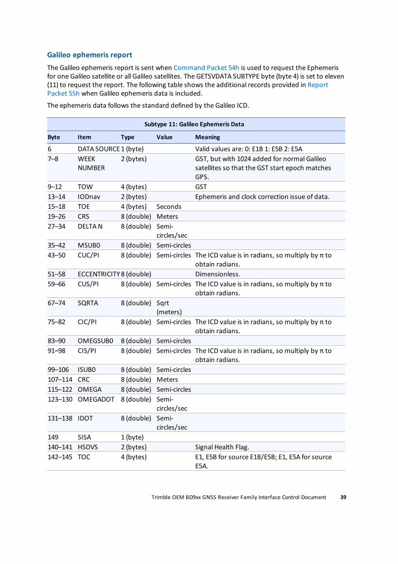
Galileo ephemeris reportThe Galileo ephemeris report is sent when Command Packet 54h is used to request the Ephemerisfor one Galileo satellite or all Galileo satellites. The GETSVDATA SUBTYPE byte (byte 4) is set to eleven(11) to request the report. The following table shows the additional records provided in ReportPacket 55h when Galileo ephemeris data is included.
The ephemeris data follows the standard defined by the Galileo ICD.
Subtype 11: Galileo Ephemeris Data
Byte Item Type Value Meaning
6 DATA SOURCE1 (byte) Valid values are: 0: E1B 1: E5B 2: E5A7–8 WEEK
NUMBER2 (bytes) GST, but with 1024 added for normal Galileo
satellites so that the GST start epoch matchesGPS.
9–12 TOW 4 (bytes) GST13–14 IODnav 2 (bytes) Ephemeris and clock correction issue of data.15–18 TOE 4 (bytes) Seconds19–26 CRS 8 (double) Meters27–34 DELTAN 8 (double) Semi-
circles/sec35–42 MSUB0 8 (double) Semi-circles43–50 CUC/PI 8 (double) Semi-circles The ICD value is in radians, so multiply by π to
obtain radians.51–58 ECCENTRICITY8 (double) Dimensionless.59–66 CUS/PI 8 (double) Semi-circles The ICD value is in radians, so multiply by π to
obtain radians.67–74 SQRTA 8 (double) Sqrt
(meters)75–82 CIC/PI 8 (double) Semi-circles The ICD value is in radians, so multiply by π to
obtain radians.83–90 OMEGSUB0 8 (double) Semi-circles91–98 CIS/PI 8 (double) Semi-circles The ICD value is in radians, so multiply by π to
obtain radians.99–106 ISUB0 8 (double) Semi-circles107–114 CRC 8 (double) Meters115–122 OMEGA 8 (double) Semi-circles123–130 OMEGADOT 8 (double) Semi-
circles/sec131–138 IDOT 8 (double) Semi-
circles/sec149 SISA 1 (byte)140–141 HSDVS 2 (bytes) Signal Health Flag.142–145 TOC 4 (bytes) E1, E5B for source E1B/E5B; E1, E5A for source
E5A.
Trimble OEM BD9xx GNSS Receiver Family Interface Control Document 39

Subtype 11: Galileo Ephemeris Data
Byte Item Type Value Meaning
146–153 AF0 8 (double) Seconds154–161 AF1 8 (double) s/s162–169 AF2 8 (double) s/s2
170–177 BGD1 8 (double) Seconds178 MODEL 1 1 (byte) Clock model for TOC/AF0–2/BGD1.179–186 BGD2 8 (double) Seconds187 MODEL 2 1 (byte) Clock model for BGD2.
---------- End of Subtype 11 ----------
Trimble OEM BD9xx GNSS Receiver Family Interface Control Document 40

QZSS ephemeris reportThe QZSS ephemeris report is sent when Command Packet 54h is used to request the Ephemeris forone QZSS satellite or all QZSS satellites. The GETSVDATA SUBTYPE byte (byte 4) is set to fourteen (14)to request the report. The first following table shows the additional records provided in ReportPacket 55h when QZSS ephemeris data is included.
The ephemeris data follows the standard defined by the ICD200, except for CUC, CUS, CIS, and CIC.These values must bemultiplied by p to become the units specified in the ICD document. Theephemeris flags are described in the second following table.
Subtype 14: QZSS Ephemeris Data
Byte Item Type Value Meaning
6 DATA SOURCE 1 (byte) Valid values are:
l 0: L1CA
l 1: L1C
l 2: L2C
l 3: L58–9 WEEK NUMBER 2 (bytes) GPS Week Number.10–11 IODC 2 (bytes)12 Reserved 1 (byte)13 IODE 1 (byte)14–17 TOW 4 (bytes)18–21 TOC 4 (bytes)22–25 TOE 4 (bytes)26–33 TGD 8 (double)34–41 AF2 8 (double)42–49 AF1 8 (double)50–57 AF0 8 (double)58–65 CRS 8 (double)66–73 DELTA n 8 (double)74–81 M sub 0 8 (double)82–89 CUC/PI 8 (double) Multiply by π to obtain ICD units.90–97 ECCENTRICITY 8 (double)98–105 CUS/PI 8 (double) Multiply by π to obtain ICD units.106–113 SQRTA 8 (double)114–121 CIC/PI 8 (double) Multiply by π to obtain ICD units.122–129 OMEG sub 0 8 (double)130–137 CIS/PI 8 (double) Multiply by π to obtain ICD units.138–145 I sub 0 8 (double)146–153 CRC 8 (double)154–161 OMEGA 8 (double)
Trimble OEM BD9xx GNSS Receiver Family Interface Control Document 41

Subtype 14: QZSS Ephemeris Data
Byte Item Type Value Meaning
162–169 OMEGADOT 8 (double)170–177 IDOT 8 (double)178–181 EPHEMERIS FLAGS 4 (long) See below.
---------- End of Subtype 14 ----------
Where FLAGS is encoded as a 32-bit value given by the following table:
Note – Not all these flags are relevant for QZSS and so are transmitted as constant values byQZSS. To facilitate code sharing with GPS almanac code, these constants are propagated throughthe system and all the relevant flags below are in the same place as for GPS.
Bit(s) Description Location
0 Data flag for L2 P-code (fixed at 1 for QZSS) Sub 1, word 4, bit 11–2 Codes on L2 channel (fixed at 10b for QZSS) Sub 1, word 3, bits 11–123 Anti-spoof flag: Y-code on: from ephemeris
(fixed at 0 for QZSS)Sub 1–5, HOW, bit 19
4–9 SV health: from ephemeris Sub 1, word 3, bits 17–2210 Fit interval flag Sub 2, word 10, bit 1711–14 URA: User Range Accuracy Sub 1, word 3, bits 13–1615 Block II: Alert flag: SV URAmay be worse than
indicated Block I: Momentum Dump flagSub 1–5, HOW, bit 18
16–18 SV Configuration: SV is Block I or Block II Sub 4, page 25, word and bit depends onSV.
19 Anti-spoof flag: Y-code on Sub 4, page 25, word and bit depends onSV.
Trimble OEM BD9xx GNSS Receiver Family Interface Control Document 42

BeiDou ephemeris reportThe ephemeris report is sent when Command Packet 54h is used to request the ephemeris for onesatellite or all satellites. The GETSVDATA SUBTYPE byte (byte 4) is set to twenty-one (21) to requestthe report. The first following table shows the additional records provided in Report Packet 55hwhen ephemeris data is included.
The ephemeris data follows the standard defined by GPS ICD-200 except for CUC, CUS, CIS, and CIC.These values must bemultiplied by π to become the units specified in the GPS ICD-200 document.
Subtype 21: GPS ephemeris data
Byte Item Type Value Meaning
6–7 EPHEMERIS WEEK # 2 (short) Ephemeris Week Number.8–9 IODC 2 (short)10 RESERVED 1 (byte)11 IODE 1 (byte)12–15 TOW 4 (long)16–19 TOC 4 (long)20–23 TOE 4 (long)24–31 TGD 8 (double)32–39 AF2 8 (double)40–47 AF1 8 (double)48–55 AF0 8 (double)56–63 CRS 8 (double)64–71 DELTAN 8 (double)72–79 M SUB 0 8 (double)80–87 CUC 8 (double) Multiply by π to obtain ICD units.88–95 ECCENTRICITY 8 (double)96–103 CUS 8 (double) Multiply by π to obtain ICD units.104–111 SQRT A 8 (double)112–119 CIC 8 (double) Multiply by π to obtain ICD units.120–127 OMEGA SUB 0 8 (double)128–135 CIS 8 (double) Multiply by π to obtain ICD units.136–143 I SUB 0 8 (double)144–151 CRC 8 (double)152–159 OMEGA 8 (double)160–167 OMEGADOT 8 (double)168–175 I DOT 8 (double)176–179 FLAGS 4 (double
word)---------- End of Subtype 21 ----------
Trimble OEM BD9xx GNSS Receiver Family Interface Control Document 43

Where FLAGS is encoded as a 32-bit value given by the following table:
Bit(s) Description Location
0 Data flag for L2 P-code Sub 1, word 4, bit 11–2 Codes on L2 channel Sub 1, word 3, bits 11–123 Anti-spoof flag:
Y-code on: from ephemeris
Sub 1–5, HOW, bit 19
4–9 SV health: from ephemeris Sub 1, word 3, bits 17–2210 Fit interval flag Sub 2, word 10, bit 1711–14 URA: User Range Accuracy Sub 1, word 3, bits 13–1615 URAmay be worse than indicated Block I:
Momentum Dump flagSub 1–5, HOW, bit 18
16–18 SV Configuration: SV is Block I or Block II Sub 4, page 25, word and bit depends onSV
19 Anti-spoof flag: Y-code on Sub 4, page 25, word and bit depends onSV
Trimble OEM BD9xx GNSS Receiver Family Interface Control Document 44

BeiDou Almanac reportThe ALMANAC report is sent when Command Packet 54h is used to request the Almanac for onesatellite or all satellites. The Command Packet 54h SUBTYPE byte (byte 4) is set to twenty-two (22)when requesting the report. Data follows the format specified by GPS ICD-200.
The following table shows the additional records provided in Report Packet 55h when almanac datais included.
Subtype 22: BeiDou Almanac
Byte Item Type Value Meaning
6–9 ALM DECODE TIME 4 (unsigned long) Full GPS seconds from the start of GPS time.10–11 AWN 2 (short)12–15 TOA 4 (unsigned long)16–23 SQRTA 8 (double)24–31 ECCENT 8 (double)32–39 ISUBO 8 (double)40–47 OMEGADOT 8 (double)48–55 OMEGSUBO 8 (double)56–63 OMEGA 8 (double)64–71 MSUBO 8 (double)72–73 ALM HEALTH 2 (short) Bit 9 (MSB): not set = satellite clock OK
Bit 8: not set = B1 Signal OK
Bits 7-3: reserved
Bit 2: not set = Nav Message OK
Bit 1 (LSB): reserved74–81**ASUBF0 8 (double)82–89**ASUBF1 8 (double)90 ALM-SRC for BeiDou 1 (byte)
---------- End of Subtype 22 ----------
Trimble OEM BD9xx GNSS Receiver Family Interface Control Document 45
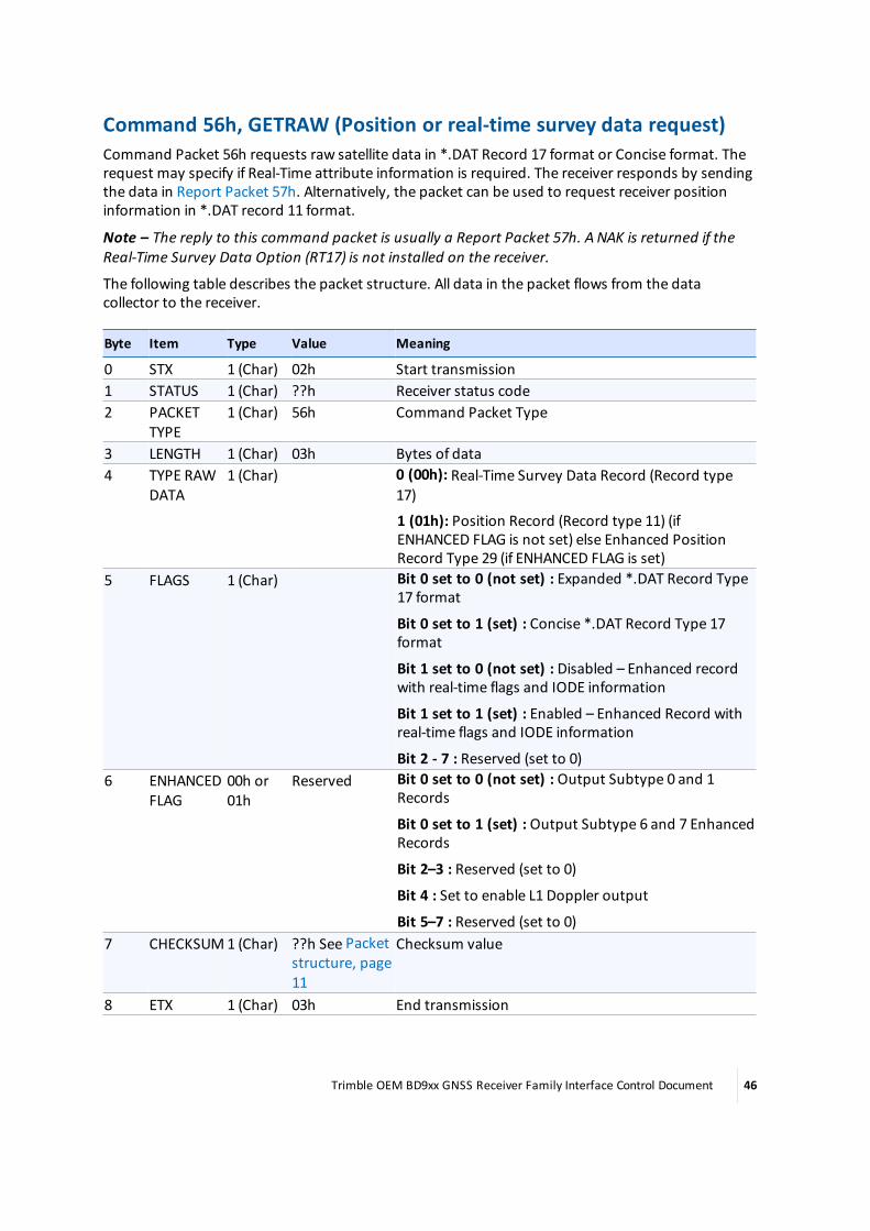
Command 56h, GETRAW (Position or real-time survey data request)Command Packet 56h requests raw satellite data in *.DAT Record 17 format or Concise format. Therequest may specify if Real-Time attribute information is required. The receiver responds by sendingthe data in Report Packet 57h. Alternatively, the packet can be used to request receiver positioninformation in *.DAT record 11 format.
Note – The reply to this command packet is usually a Report Packet 57h. A NAK is returned if theReal-Time Survey Data Option (RT17) is not installed on the receiver.
The following table describes the packet structure. All data in the packet flows from the datacollector to the receiver.
Byte Item Type Value Meaning
0 STX 1 (Char) 02h Start transmission1 STATUS 1 (Char) ??h Receiver status code2 PACKET
TYPE1 (Char) 56h Command Packet Type
3 LENGTH 1 (Char) 03h Bytes of data4 TYPE RAW
DATA1 (Char) 0 (00h): Real-Time Survey Data Record (Record type
17)
1 (01h): Position Record (Record type 11) (ifENHANCED FLAG is not set) else Enhanced PositionRecord Type 29 (if ENHANCED FLAG is set)
5 FLAGS 1 (Char) Bit 0 set to 0 (not set) : Expanded *.DAT Record Type17 format
Bit 0 set to 1 (set) : Concise *.DAT Record Type 17format
Bit 1 set to 0 (not set) : Disabled – Enhanced recordwith real-time flags and IODE information
Bit 1 set to 1 (set) : Enabled – Enhanced Record withreal-time flags and IODE information
Bit 2 - 7 : Reserved (set to 0)6 ENHANCED
FLAG00h or01h
Reserved Bit 0 set to 0 (not set) : Output Subtype 0 and 1Records
Bit 0 set to 1 (set) : Output Subtype 6 and 7 EnhancedRecords
Bit 2–3 : Reserved (set to 0)
Bit 4 : Set to enable L1 Doppler output
Bit 5–7 : Reserved (set to 0)7 CHECKSUM1 (Char) ??h See Packet
structure, page11
Checksum value
8 ETX 1 (Char) 03h End transmission
Trimble OEM BD9xx GNSS Receiver Family Interface Control Document 46
Note – Using the 56h command, the output is always at the port through which the command wassent. For example, if the command was sent through RS-232 serial then the output is through thesame port and if the command is sent using USB then the 57h output is through the USB port.
Trimble OEM BD9xx GNSS Receiver Family Interface Control Document 47

Response 57h, RAWDATA (Position or real-time survey data report)Report Packet 57h is sent in response to Command 56h GETRAW or in response to a request forstreamed Real-Time Survey Data via the 64h APPFILE command. This responsemay containExpanded Format (".DAT" record 17 style) raw satellite measurements, "Concise Format"measurements, the current computed position or an Event Mark. An NAK is returned if the Real-Time Survey data option is not installed and the user requests this via the following options:
l Command Packet 56h
l Real-Time Survey Data steaming that can be enabled using the 64h Application File command
The raw satellite data responses following either the "Expanded" or the "Concise" format and arelikely to span more than one RAWDATA reply. To overcome this, page information and an epochcounter are supplied as an extended framing. The first and subsequent RAWDATA record pages willbe filled with a maximum of 248 bytes consisting of 4 bytes of page and flag information and 244bytes of raw satellite data. The raw satellite data will be split where ever the 244 byte boundary falls,regardless of internal variable boundaries. Therefore the external device receiving themultiple pagesmust reconstruct the raw satellite record using the 244 byte pages before parsing the data.
All data in the packet flows from the receiver to the data collector.
Byte Item Type Value Meaning
0 STX 1(Char)
02h Start Transmission
1 STATUS 1(Char)
??h Receiver Status Code
2 PACKET TYPE 1(Char)
57h Response Packet Type
3 LENGTH 1(Char)
??h Bytes of data
----- RESPONSE HEADER -----4 Record Type 1
(byte)00h, 01h,02h, 06h,and 07h
Record Type indicates which raw data record type is beingsent:
l 0: Real-time GPS survey data (RT-17)
l 1: Position Record (RT-11)
l 2: Event Mark
l 6: Real-time GNSS Survey Data (type 27)
l 7: Enhanced Position Record (type 29)5 Page Number 1
(byte)Page Counter indicates howmany pages there are for thisepoch and what this page number is (for example, 10f 3, 2of 3, 3 of 3).
This byte is split into two sections of 4 bits allowing for 15pages where:
bits 0–3: Page total
Trimble OEM BD9xx GNSS Receiver Family Interface Control Document 48

Byte Item Type Value Meaning
bits 4–7: Current page number
So, for example, 0x23would indicate the second page outof three.
6 Reply Number1(byte)
00h–FFh Reply Number is a 0-255 rollover counter which isincremented with every reply but remains constantacross pages within one reply. This value should bechecked on 2nd and subsequent pages to ensure thatpages of the same reply are recombined rather thanthose from different reply.
7 RecordInterpretationFlags
1(byte)
RECORD INTERPRETATION FLAGS indicates specialattributes of the record that must be used in parsingvalues. Defined values are:
l bit 0 set : Concise format
l bit 1 set : Enhanced Record with real-time flags andIODE information
l bits 2 - 7 : reserved----- DATA RECORDS – Subtype 0, 1, 2, 6, or 7 -----
Data from one of the records that are encoded in type 57h records, as indicated by byte #4 RECORDTYPE. An individual record may extend over several RAWDATA packets. See:
l Data record subtype 0: Real-time survey data (record type 17)—Expanded Format, page 50
l Data record subtype 0: Real-time survey data (record type 17)—Concise Format, page 52
l Data record subtype 1: Position (record type 11), page 54
l Data record subtype 2: Event mark (record type 19), page 56
l Data record subtype 6: Real-time GNSS Survey Data (record type 27)1
l Data record subtype 7: Enhanced position (record type 29), page 57Last byteof data +1
CHECKSUM Char ??h SeePacketstructure,page 11.
Checksum Value
Last byteof data +2
ETX Char 03h End Transmission
1The record type 27 message contains raw measurement information for all GNSS satellites, but the record type 17 messages contain raw measurement
information for only GPS satellites. Because this information is considered proprietary by some parts of Trimble, users are requested to contact their dealeror sales person and sign aNon-Disclosure Agreement in order to obtain the documentation of this message format.
Trimble OEM BD9xx GNSS Receiver Family Interface Control Document 49

Data record subtype 0: Real-time survey data (record type 17)—Expanded FormatThe following table shows the additional records provided in Report Packet 57h when ExpandedRecord format is enabled with Command Packet 56h.
See also Data record subtype 0: Real-time survey data (record type 17)—Concise Format, page 52.
Subtype 0: Real-time Survey Data (Record 17) – Expanded Format
Byte Item Type Value Notes
(Expanded Format) Header (17 bytes)8–15 RECEIVE TIME 8 (double) msecs Receive timewithin the current GPS week (common
to code and phase data).16–23 CLOCK OFFSET 8 (double) msecs Clock offset value. A value of 0.0 indicates that clock
offset is not known.24 # OF SVS IN
RECORD1 (byte) blocks Number of SV data blocks included in record.
Begin data for first satellite in constellation (block repeated for up to 12 SVs)
Begin Real-Time Survey Data (8 bytes)SV PRN 1 (byte) 01h–20h Pseudorandom number of satellite (1–32).FLAGS1 1 (byte) Indicates what data is loaded, is valid, etc.
bit 0 set L2 data loaded and phase valid (see also b6)
bit 1 set L1 cycle-slip (since last record 17write)
bit 2 set L2 cycle-slip (since last record 17write)
bit 3 L1 phase lock point (redundant, fordiagnostics)
bit 4 set L1 phase valid (lock-point valid)
bit 5 set L2 pseudo range valid, reset = squared-L2phase (for 4000SSE receivers bit 5 = bit 0)
bit 6 set L1 data valid (non-zero but bytes alwayspresent) (see also bit 4), reset = only L2 data loaded(see FLAG STATUS field below)
bit 7 set New position computed this receiver cycleFLAGS2 1 (byte) bit 0 ( L1 tracking Mode) 0: C/A Code 1 : P-code
bit 1 ( L2 tracking Mode) 0: C/A Code 1 : P-code
bit 2 (L2 Tracking Encryption Code) 0 : Off 1 : On
bit 3 ( Filtered L1 pseudorange corrections) ) 0 : Off 1: On
bits 4–7 reservedFLAG STATUS 1 (byte) Indicates whether FLAGS2 is valid (not present for
concise format)
bit 0 = 0 (Bit 6 of FLAGS1 and bit 0 - 7 of FLAGS2 areundefined
Trimble OEM BD9xx GNSS Receiver Family Interface Control Document 50

Subtype 0: Real-time Survey Data (Record 17) – Expanded Format
Byte Item Type Value Notes
(Expanded Format) Header (17 bytes)bit 0 = 1 (Bit 6 of FLAGS1 and bit 0 - 7 of FLAGS2 arevalid (always set for RAWDATA)
bits 1–7 : reserved (set to 0)ELEVATIONANGLE
2 (signedinteger)
Degrees Satellite elevation angle (+/-)
AZIMUTH 2 (signedinteger)
Degrees Satellite azimuth.
L1 Data: available if bit 6 of FLAGS1 set (40 bytes)L1 SNR 8 (double) dB Measure of satellite signal strength.L1 FULL L1 C/ACODE P-RANGE
8 (double) meters Full L1 C/A code or P-code pseudorange (see bit 0 ofFLAGS2).
L1CONTINUOUSPHASE
8 (double) L1 cycles L1 Continuous Phase. Range-Rate sign convention:When pseudorange is increasing, the phase isdecreasing and the Doppler is negative.
L1 DOPPLER 8 (double) Hz L1 Doppler.L1 RESERVED 8 (double) 0.0
L2 Data: Available if bit 0 of FLAGS1 set (24 bytes)L2 SNR 8 (double) dB Measure of satellite signal strengthL2CONTINUOUSPHASE
8 (double) L2 cycles L2 Continuous Phase is in L2 cycles if bit 5 of FLAGS1= 1
L2 P-CODE – L1C/A CODEPSEUDORANGE
8 (double) meters L2 P-Code or L2 Encrypted Code (see bit 1 and bit 2of FLAGS2)— L1 C/A-Code or P-code (see bit 0 ofFLAGS2) pseudorange (valid only if bit 5 of FLAGS1 =1)
Begin Enhanced Record if bit 1 of the Record Interpretation Flags byte is set to 1 (12 bytes)IODE 1 (byte) 00h–FFh Issue of Data EphemerisL1 SLIPCOUNTER
1 (byte) 00h–FFh Roll-over counter is incremented for eachoccurrence of detected cycle-slips on L1 carrierphase
L2 SLIPCOUNTER
1 (byte) 00h–FFh Roll-over counter is incremented for eachoccurrence of detected cycle-slips on the L2 carrierphase. The counter always increments when L2changes from C/A code to Encrypted code and viceversa.
RESERVED 1 (byte) –L2 DOPPLER 8 (double) Hz
Repeat previous bytes for remaining satellites in constellation---------- End of Subtype 0 ----------
Trimble OEM BD9xx GNSS Receiver Family Interface Control Document 51

Data record subtype 0: Real-time survey data (record type 17)—Concise FormatThe following table shows the additional records provided in Report Packet 57h when ConciseRecord format is enabled with Command Packet 56h.
See also Data record subtype 0: Real-time survey data (record type 17)—Expanded Format, page 50.
Subtype 0: Real-time Survey Data (Record 17) – Concise Format
Byte Item Type Value Notes
(Concise Format) Header (17 bytes)8–15 RECEIVE TIME 8 (double) msecs Receive timewithin the current GPS week (common
to code and phase data).16–23 CLOCK OFFSET 8 (double) msecs Clock offset value. A value of 0.0 indicates that clock
offset is not known.24 # OF SVS IN
RECORD1 (byte) blocks Number of SV data blocks included in record.
Begin data for first satellite in constellation (block repeated for up to 12 SVs)
Begin Real-Time Survey Data (6 bytes)SV PRN 1 (byte) 01h–20h Pseudorandom number of satellite (1–32).FLAGS1 1 (byte) Indicates what data is loaded, is valid, etc.
bit 0 set L2 data loaded and phase valid (see also b6)
bit 1 set L1 cycle-slip (since last record 17write)
bit 2 set L2 cycle-slip (since last record 17write)
bit 3 L1 phase lock point (redundant, for diagnostics)
bit 4 set L1 phase valid (lock-point valid)
bit 5 set L2 pseudo range valid, reset = squared-L2phase (for 4000SSE receivers bit 5 = bit 0)
bit 6 set L1 data valid (non-zero but bytes alwayspresent) (see also bit 4), reset = only L2 data loaded(see FLAG STATUS field below)
bit 7 set New position computed this receiver cycleFLAGS2 1 (byte) bit 0 ( L1 tracking Mode) 0: C/A Code 1 : P-code
bit 1 ( L2 tracking Mode) 0: C/A Code 1 : P-code
bit 2 (L2 Tracking Encryption Code) 0 : Off 1 : On
bit 3 ( Filtered L1 pseudorange corrections) ) 0 : Off 1: On
bits 4–7 reservedELEVATIONANGLE
1 (signedinteger)
Degrees Satellite elevation angle (+/-)
AZIMUTH 2 (signedinteger)
Degrees Satellite azimuth.
L1 Data: available if bit 6 of Flags 1 set (21 bytes)
Trimble OEM BD9xx GNSS Receiver Family Interface Control Document 52

Subtype 0: Real-time Survey Data (Record 17) – Concise Format
Byte Item Type Value Notes
(Concise Format) Header (17 bytes)L1 SNR 1 (byte) dB*4 Measure of satellite signal strength.L1 FULL L1 C/ACODE P-RANGE
8 (double) meters Full L1 C/A code or P-code pseudorange (see bit 0 ofFLAGS2).
L1CONTINUOUSPHASE
8 (double) L1 cycles L1 Continuous Phase. Range-Rate sign convention:When pseudorange is increasing, the phase isdecreasing and the Doppler is negative.
L1 DOPPLER 4 (float) Hz L1 Doppler.L2 Data: Available if bit 0 of FLAGS1 set (13 bytes)
L2 SNR 1 (byte) dB*4 Measure of satellite signal strengthL2CONTINUOUSPHASE
8 (double) L2 cycles L2 Continuous Phase is in L2 cycles if bit 5 of FLAGS1= 1
L2 P-CODE – L1C/A CODEPSEUDORANGE
4 (float) meters L2 P-Code or L2 Encrypted Code (see bit 1 and bit 2of FLAGS2)— L1 C/A-Code or P-code (see bit 0 ofFLAGS2) pseudorange (valid only if bit 5 of FLAGS1 =1)
Begin Enhanced Record if bit 1 of the Record Interpretation Flags byte is set to 1 (3 bytes)IODE 1 (byte) 00h–FFh Issue of Data EphemerisL1 SLIPCOUNTER
1 (byte) 00h–FFh Roll-over counter is incremented for each occurrenceof detected cycle-slips on L1 carrier phase
L2 SLIPCOUNTER
1 (byte) 00h–FFh Roll-over counter is incremented for each occurrenceof detected cycle-slips on the L2 carrier phase. Thecounter always increments when L2 changes fromC/A code to Encrypted code and vice versa.
Repeat previous bytes for remaining satellites in constellation---------- End of Subtype 0 ----------
Trimble OEM BD9xx GNSS Receiver Family Interface Control Document 53
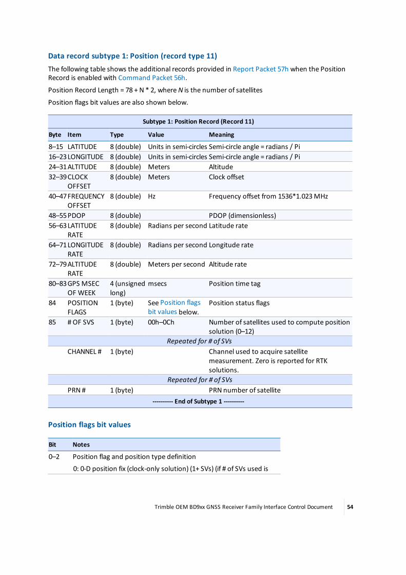
Data record subtype 1: Position (record type 11)The following table shows the additional records provided in Report Packet 57h when the PositionRecord is enabled with Command Packet 56h.
Position Record Length = 78 + N * 2, whereN is the number of satellites
Position flags bit values are also shown below.
Subtype 1: Position Record (Record 11)
Byte Item Type Value Meaning
8–15 LATITUDE 8 (double) Units in semi-circles Semi-circle angle = radians / Pi16–23LONGITUDE 8 (double) Units in semi-circles Semi-circle angle = radians / Pi24–31ALTITUDE 8 (double) Meters Altitude32–39CLOCK
OFFSET8 (double) Meters Clock offset
40–47FREQUENCYOFFSET
8 (double) Hz Frequency offset from 1536*1.023MHz
48–55PDOP 8 (double) PDOP (dimensionless)56–63LATITUDE
RATE8 (double) Radians per second Latitude rate
64–71LONGITUDERATE
8 (double) Radians per second Longitude rate
72–79ALTITUDERATE
8 (double) Meters per second Altitude rate
80–83GPS MSECOF WEEK
4 (unsignedlong)
msecs Position time tag
84 POSITIONFLAGS
1 (byte) See Position flagsbit values below.
Position status flags
85 # OF SVS 1 (byte) 00h–0Ch Number of satellites used to compute positionsolution (0–12)
Repeated for # of SVsCHANNEL # 1 (byte) Channel used to acquire satellite
measurement. Zero is reported for RTKsolutions.
Repeated for # of SVsPRN # 1 (byte) PRN number of satellite
---------- End of Subtype 1 ----------
Position flags bit values
Bit Notes
0–2 Position flag and position type definition
0: 0-D position fix (clock-only solution) (1+ SVs) (if # of SVs used is
Trimble OEM BD9xx GNSS Receiver Family Interface Control Document 54

Bit Notes
non-zero)
1: 1-D position fix (height only with fixed latitude/longitude) (2+ SVs)
2: 2-D position fix (fixed height and clock) (2+ SVs)
3: 2-D position fix (fixed height) (3+ SVs)
4: 3-D solution (4+ SVs)
5: 3D Solution (4+ SVs)Wide Area/Network RTK3 RTK Solution: if set, position is fixed RTK, else float RTK
0: Floating integer ambiguity
1: Fixed integer ambiguity4 DGPS Differential Corrections
0: No DGPS corrections are used in position computation
1: DGPS corrections are used to compute position5 Reserved (set to zero)6 RTK Solution: if set, position is from RTK (including Location RTK)
0: False
1: True7 Position Derived While Static (RTK only)
0: False
1: TrueBit combinations:
l Bit 4 and 6 are set if the solution type is SBAS
l Bit 5 and 4 are set if the solution type is OmniSTAR HP/XP
Trimble OEM BD9xx GNSS Receiver Family Interface Control Document 55

Data record subtype 2: Event mark (record type 19)The following table shows the additional records provided in Report Packet 57h when the EventMark record is enabled with Command Packet 56h.
Subtype 2: Event Mark (Record 19)
Byte Item Type Value Meaning
8 Event Source 1 (byte) 00h–05h 0: External Event
1: Reserved
2: Reserved
3: Reserved
4: RS-232 Event
5: Reserved9 Event Port 1 (byte) 00h–05h 0: Not Applicable
1: 1st Event Port or Serial Port 1
2: 2nd Event Port or Serial Port 2
3: Serial Port 3
4: Serial Port 410–11 Event Number 2 (short) Event record tag number, incremented with each event12–19 GPS time 8 (double) msec GPS time of week in milliseconds
---------- End of Subtype 2 ----------
Trimble OEM BD9xx GNSS Receiver Family Interface Control Document 56

Data record subtype 7: Enhanced position (record type 29)The following table shows the additional records provided in Report Packet 57h when the EnhancedPosition record is enabled with Command Packet 56h.
Where increments are present, divide the value by the increment to scale to the indicated units.
For example: LONGITUDE/2^39
Subtype 7: Enhanced Position (Record 29)
Byte Item Type Value Meaning
8 BLOCK LENGTH 1 (byte) Indicates the length of the current datablock, including the BLOCK LENGTH byte.
9–10 WEEK NUMBER 2 (short) GPS week number of the observation.11–14 RECEIVER TIME 4 (long) msec Receiver time (milliseconds of the week) of
the observation.15 RECEIVER
MOTION STATE1 (byte) Valid values are 0 (kinematic) or 1 (static).
16 NUMBER SVsTRACKED
1 (byte) Number of SVs actually tracked.
17 NUMBER OF SVsUSED INSOLUTION
1 (byte) Number of SVs actually used in calculatingthe solution.
18 RESERVED 1 (byte) RESERVED19 POSITION
SYSTEM FLAGS1 (byte) See Position systems flags values, page 60.
20 POSITIONSOLUTIONMODE
1 (byte) See Position solution mode values, page 60.
21 POSITIONAUGMENTATIONTYPE
1 (byte) See Position augmentation type values,page 61.
22 POSITIONPROCESSINGTYPE
1 (byte) See Position processing type values, page61.
Position Block (53 bytes)23 BLOCK LENGTH 1 (byte) Indicates the length of the current data
block, including the BLOCK LENGTH byte.24–29 LATITUDE 6 (integer) Degrees Range = +/-90 degrees. Increment = 2^40,
approximately 9.1e–13 degrees.30–35 LONGITUDE 6 (integer) Degrees Range = +/-180 degrees. Increment = 2^39,
approximately 1.8e–12 degrees.36–39 ALTITUDE 4 (long) Meters Range = +/-524,288m. Increment = 2^12,
approximately 0.24mm.40–43 VELOCITY N 4 (long) Meters/sec Range = +/-1024m/s. Increment = 2^21,
Trimble OEM BD9xx GNSS Receiver Family Interface Control Document 57

Subtype 7: Enhanced Position (Record 29)
Byte Item Type Value Meaning
approximately 0.00048mm/s.44–47 VELOCITY E 4 (long) Meters/sec Range = +/-1024m/s. Increment = 2^21,
approximately 0.00048mm/s.48–51 VELOCITY U 4 (long) Meters/sec Range = +/-1024m/s. Increment = 2^21,
approximately 0.00048mm/s.52–55 RECEIVER CLOCK
OFFSET4 (long) Milliseconds Range = +/-32msec. Increment = 2^26,
approximately 1.5e–8msec.56–59 RECEIVER CLOCK
DRIFT4 (long) Clock drift in PPMRange = +/-16,384 ppm. Increment = 2^17,
approximately 7.6e–6 ppm.60–61 HDOP 2 (short) Unitless Range = 0–4096. Increment = 2^4,
approximately 0.0625.62–63 VDOP 2 (short) Unitless Range = 0–4096. Increment = 2^4,
approximately 0.0625.64–65 TDOP 2 (short) Unitless Range = 0–4096. Increment = 2^4,
approximately 0.0625.66–67 1SIGMAN 2 (short) Meters Range = 0–32m. Increment = 2^11,
approximately 4.9e–4m.68–69 1SIGMA E 2 (short) Meters Range = 0–32m. Increment = 2^11,
approximately 4.9e–4m.70–71 1SIGMAU 2 (short) Meters Range = 0–32m. Increment = 2^11,
approximately 4.9e–4m.72–73 RMS 2 (short) Meters Range = 0–4m. Increment = 2^14,
approximately 6.1e–5m.74–75 UNIT STD DEV 2 (short) Square root of
the unit varianceRange = 0–32. Increment = 2^11,approximately 4.9e–4.
RTK Solutions Block: available if POSITION AUGMENTATION TYPE is 3, 4, 5, or 6 (5 bytes).BLOCK LENGTH 1 (byte) Indicates the length of the current data
block, including the BLOCK LENGTH byte.RTK MODE 1 (byte) 0 or 1 Valid values are 0 (synchronized) or 1 (low
latency).AGE OF DATA 2 (short) Seconds Range is 0 to 1000 seconds, increment =
2^6.RESERVED 1 (byte)GLONASS Block: Available if bit 1 is set in POSITION SYSTEMS FLAGS (12 bytes).BLOCK LENGTH 1 (byte) Indicates the length of the current data
block, including the BLOCK LENGTH byte.GPS GLONASSSYSTEM TIMEOFFSET
4 (long) Nanoseconds Range = +/-32,768 nsec. Increment = 2^16.
GPS GLONASSTIME DRIFT
4 (long) Nanoseconds/secRange = +/-32,768 nsec. Increment = 2^16.
Trimble OEM BD9xx GNSS Receiver Family Interface Control Document 58

Subtype 7: Enhanced Position (Record 29)
Byte Item Type Value Meaning
GLONASS FLAGS 1 (byte) Bit 0 set: GLONASS TDOP.GLONASS TDOP 2 (short) If present, see
GLONASS FLAGSbit 0
Increment = 2^4.
Inter-System Clock Offset Block: Available if bit 4 is set in POSITION SYSTEMS FLAGS (?? bytes).BLOCK LENGTH 1 (byte) Indicates the length of the current data
block, including the BLOCK LENGTH byte.INTER-SYSTEMCLOCK OFFSETHEADER
1 (byte) Bit 0-3: Satellite clock system to which timeoffsets are referenced. See Inter-SystemClock Offset SV System bit values.
Bit 4-6: Number of System Time Offsetsstored (n = 0-7)
Bit 7: Onemore header byte follows.Repeated for the number of system time offsets stored.
INTER-SYSTEMCLOCK OFFSETINFO
1 (byte) Bit 0-3: Satellite clock system. See Inter-System Clock Offset SV System bit values.
Bit 4-6: Number of bytes (“M”)
Bit 7: Onemore info byte follows.INTER-SYSTEMCLOCK OFFSET
"M" bytes milliseconds This is an M-byte signed integer in units ofmilliseconds/2^28. The lowest bit has avalue of 0.0037 ns or 1.12mm. The rangebased on the number of bytes is:
1 bytes: +/- 0.47 ns
2 bytes: +/- 122.07 ns
3 bytes: +/- 31250.00 ns (31 us)
4 bytes: +/- 8ms
5 bytes: +/- 2.048 s
6 bytes: +/- 524.29 s
7 bytes: +/- 37.283 hours ( LSB = 4.48mm iftop 2 bits of 7th byte are used )
SV Block (SV ID, SV TYPE, and SV FLAGS are repeated for the number of SVs tracked. Trimblerecommends using the BLOCK LENGTH to determine the number of SVs (4 bytes).BLOCK LENGTH 1 (byte) Indicates the length of the current data
block, including the BLOCK LENGTH byte.SV ID 1 (byte)SV TYPE 1 (byte) SV TYPE is the GNSS system or satellite type.
Defined values are
0: GPS
1: SBAS (WAAS, EGNOS, MSAS, etc.)
Trimble OEM BD9xx GNSS Receiver Family Interface Control Document 59

Subtype 7: Enhanced Position (Record 29)
Byte Item Type Value Meaning
2: GLONASS
3: Galileo
4: QZSS
7: BeiDouSV FLAGS 1 (byte) SV FLAGS is a bitmapped field with the
following values:
Bit 0: SV unhealthy
Bit 1: SV used in position solution
Bit 2:RAIM fault
Bit 3–7: RESERVEDRepeat previous bytes for remaining satellites in constellation
---------- End of Subtype 7 ----------
Position systems flags valuesThe following table shows the values for the Position System Flags byte in the Subtype 7: Enhancedposition record.
Value Notes
0 GPS1 GLONASS2 RESERVED3 RESERVED4 System Time Offsets block present5 RESERVED6 Reserved7 When set in this, or any subsequent flags
byte, another flags byte follows.
Position solution mode valuesThe following table shows the values for the Position Solution Mode byte in the Subtype 7:Enhanced position record.
Value Notes
0 Old fix1 Clock only2 Overdetermined clock only3 2D solution with fixed height and clock4 2D solution with fixed height5 3D solution
Trimble OEM BD9xx GNSS Receiver Family Interface Control Document 60
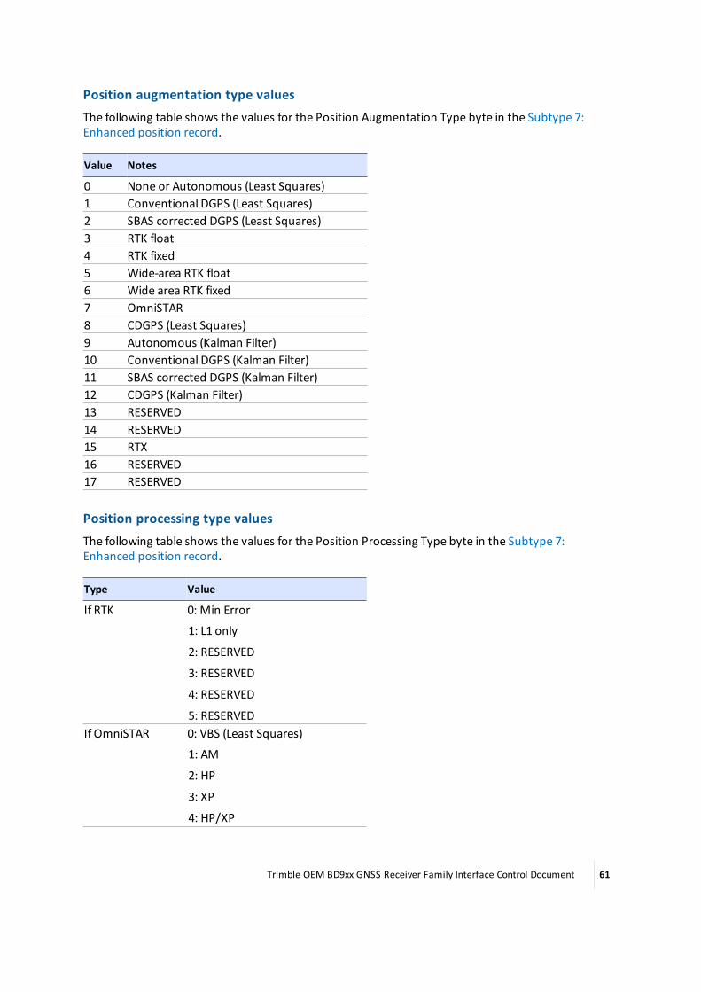
Position augmentation type valuesThe following table shows the values for the Position Augmentation Type byte in the Subtype 7:Enhanced position record.
Value Notes
0 None or Autonomous (Least Squares)1 Conventional DGPS (Least Squares)2 SBAS corrected DGPS (Least Squares)3 RTK float4 RTK fixed5 Wide-area RTK float6 Wide area RTK fixed7 OmniSTAR8 CDGPS (Least Squares)9 Autonomous (Kalman Filter)10 Conventional DGPS (Kalman Filter)11 SBAS corrected DGPS (Kalman Filter)12 CDGPS (Kalman Filter)13 RESERVED14 RESERVED15 RTX16 RESERVED17 RESERVED
Position processing type valuesThe following table shows the values for the Position Processing Type byte in the Subtype 7:Enhanced position record.
Type Value
If RTK 0: Min Error
1: L1 only
2: RESERVED
3: RESERVED
4: RESERVED
5: RESERVEDIf OmniSTAR 0: VBS (Least Squares)
1: AM
2: HP
3: XP
4: HP/XP
Trimble OEM BD9xx GNSS Receiver Family Interface Control Document 61

Type Value
5: HPG2
6: G2
7: VBS (Kalman Filter)
8: MS 9: L1
Inter-system clock offset SV systems valuesThe following table shows the values for the INTER-SYSTEM CLOCK OFFSET SV SYSTEMS byte in theSubtype 7: Enhanced position record. Note that these values differ from the “Position SystemsFlags”.
Value Notes
0 GPS1 SBAS2 GLONASS3 Galileo4 QZSS5 BeiDou6 RESERVED7 RESERVED
Trimble OEM BD9xx GNSS Receiver Family Interface Control Document 62

Application file packetsTo send application files to the receiver, upload the files via the web interface, or create theapplication files with a custom software program.
Application files contain a collection of individual records that fully prescribe the operation of thereceiver. Application files are transferred using the standard Data Collector Format packet format.
Each application file can be tailored to meet the requirements of separate and unique applications.Up to 12 application files can be stored within the receiver for activation at a later date.
The two important application files in the receiver are:
Name Function
DEFAULT Permanently stored application file containing the receiver’s factory default settings. Thisapplication file is used when the receiver is reset to the factory default settings.
CURRENTHolds the current settings of the receiver.
Individual records within an existing application file can be updated using the software toolsincluded with the receiver. For example, the OUTPUTMESSAGES record in an application file can beupdated without affecting the parameter settings in other application file records.
Application files can be started immediately and/or the files can be stored for later use.
Once applications files are transferred into memory, command packets can be used to manage thefiles. Command packets are available for transferring, selecting, and deleting application files.
If any part of the application record data is invalid, then the receiver ignores the entire record. Thereceiver reads a record using the embedded length. Any extraneous data is ignored. This allows forbackward compatibility when the record length is increased to add new functions.
If you are concerned about application files producing the same results on future receivers, makesure that the application records do not contain extraneous data.
Command Packet 64h is sent to create, replace, or report on an application file. The commandpacket requests the application file by System File Index.
For detailed information about application files and for guidelines about using application files tocontrol remote devices, see Response 64h, APPFILE (Application file record report), page 93.
Packet pagingSince an application file contains a maximum of 248 bytes (all records are optional) of data andexceeds the byte limit for RS-232 Serial Interface Specification packets, Command Packet 64h isdivided into several subpackets called pages. The PAGE INDEX byte (byte 5) identifies the packetpage number and theMAXIMUM PAGE INDEX byte (byte 6) indicates themaximum number ofpages in the report.
The first and subsequent pages are filled with a maximum of 248 bytes consisting of 3 bytes of pageinformation and 245 bytes of application file data. The application file data is split wherever the 245byte boundary falls. Therefore the remote device sending the Command Packet pages mustconstruct the application file using the 248 byte pages before sending the file to the receiver.
To prevent data mismatches, each report packet is assigned a Transmission Block Identifier (byte 4)which gives the report pages a unique identity in the data stream. The software on the remote
Trimble OEM BD9xx GNSS Receiver Family Interface Control Document 63

device can identify the pages associated with the report and reassemble the application file usingbytes 4–6.
To save the Command Packet 64h in an application file format, the first two bytes of the file mustindicate the length of the command packet in bytes. These bytes are in a little endian format as aUINT16. The bytes of the Command Packet 64h must then follow. All pages of the Command Packet64h must be included in the file.
Trimble OEM BD9xx GNSS Receiver Family Interface Control Document 64

Command 64h, APPFILE (Application file record)The following table shows the structure of the report packet containing the application file. All datain the packet flows from the data collector to the receiver.
Byte Item Type Value Notes
0 STX 1(Char)
02h Start transmission.
1 STATUS 1(Char)
00h Receiver status code.
2 PACKET TYPE 1(Char)
64h Command Packet 64h.
3 LENGTH 1(Char)
00h Data byte count.
4 TRANSMISSIONNUMBER
1(Char)
00h–FFh A Transmission Number is a unique transmissionserial number ranging from 0-255, typicallyincrementing by 1 each time an application file issent.
5 PAGE INDEX 1(Char)
00h–FFh Index number (0–255) assigned to the current page.
6 MAXIMUMPAGE INDEX
1(Char)
00h–FFh Index number (0–255) assigned to the last page of thepacket.
----- FILE CONTROL INFORMATION BLOCK -----
See File control information block, page 67.
----- APPLICATION FILE RECORDS ----- These are provided in the following order:
l File storage record
l General controls record
l Serial port baud/format record
l Reference (base) node record
l GPS SV enable/disable record
l GLONASS SV enable/disable record
l QZSS SV enable/disable record
l Galileo SV enable/disable record
l BeiDou SV enable/disable record
l SBAS SV enable/disable record
l Output message record
l Antenna record
l Device control record
l Static/kinematic record
Trimble OEM BD9xx GNSS Receiver Family Interface Control Document 65

Byte Item Type Value Notes
l Multiplexed port control record
l Vector antenna record
l GNSS heading attitude recordLength + 4 CHECKSUM CHAR Checksum value. See Packet structure, page 11.Length + 5 ETX CHAR 03h End transmission.
After all pages of the 64h command are sent, the receivers ACK or NAK this command.
Trimble OEM BD9xx GNSS Receiver Family Interface Control Document 66
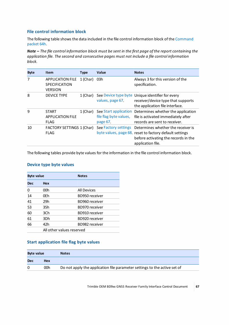
File control information blockThe following table shows the data included in the file control information block of the Commandpacket 64h.
Note – The file control information block must be sent in the first page of the report containing theapplication file. The second and consecutive pages must not include a file control informationblock.
Byte Item Type Value Notes
7 APPLICATION FILESPECIFICATIONVERSION
1 (Char) 03h Always 3 for this version of thespecification.
8 DEVICE TYPE 1 (Char) See Device type bytevalues, page 67.
Unique identifier for everyreceiver/device type that supportsthe application file interface.
9 STARTAPPLICATION FILEFLAG
1 (Char) See Start applicationfile flag byte values,page 67.
Determines whether the applicationfile is activated immediately afterrecords are sent to receiver.
10 FACTORY SETTINGSFLAG
1 (Char) See Factory settingsbyte values, page 68.
Determines whether the receiver isreset to factory default settingsbefore activating the records in theapplication file.
The following tables provide byte values for the information in the file control information block.
Device type byte values
Byte value Notes
Dec Hex
0 00h All Devices14 0Eh BD950 receiver41 29h BD960 receiver53 35h BD970 receiver60 3Ch BD910 receiver61 3Dh BD920 receiver66 42h BD982 receiver
All other values reserved
Start application file flag byte values
Byte value Notes
Dec Hex
0 00h Do not apply the application file parameter settings to the active set of
Trimble OEM BD9xx GNSS Receiver Family Interface Control Document 67

Byte value Notes
Dec Hex
parameters when the transfer is complete.1 01h Apply application file records immediately.
Factory settings byte values
Byte value Notes
Dec Hex
0 00h Alter receiver parameters only as specified in the application file. Leaveunspecified settings alone.
1 01h Set all controls to factory settings prior to applying the application file.
Application file records
File storage recordThe file storage record indicates the application file creation date and time, and providesidentification information required to store the file in memory. When included in the application file,this record must be the first record in the file.
The following table shows the additional records provided when the file storage record is includedwith Command Packet 64h.
Byte Item Type Value Notes
0 RECORD TYPE 1(Char)
00h File Storage Record.
1 RECORDLENGTH
1(Char)
0Dh Number of bytes in record, excluding bytes0 and 1.
2–9 APPLICATIONFILE NAME
8(Chars)
ASCII text A...Z, a...z, _(underscore)
Eight-character name for the applicationfile.
10 YEAR OFCREATION
1(Char)
00h–FFh Year when application file is created,ranging from 00–255 (1900 = 00).
11 MONTH OFCREATION
1(Char)
01h–0Ch Month when application file is created (01–12).
12 DAY OFCREATION
1(Char)
00h–1Fh Day of themonth when application file iscreated (00–31).
13 HOUR OFCREATION
1(Char)
00h–17h Hour of the day when application file iscreated (00-23).
14 MINUTES OFCREATION
1(Char)
00h–3Bh Minutes of the hour when application file iscreated (00–59).
If multiple applications files or Command Packet 64h messages are sent with the same APPLICATIONFILE NAME, these will overwrite any existing files with the same name (regardless of upper and/or
Trimble OEM BD9xx GNSS Receiver Family Interface Control Document 68
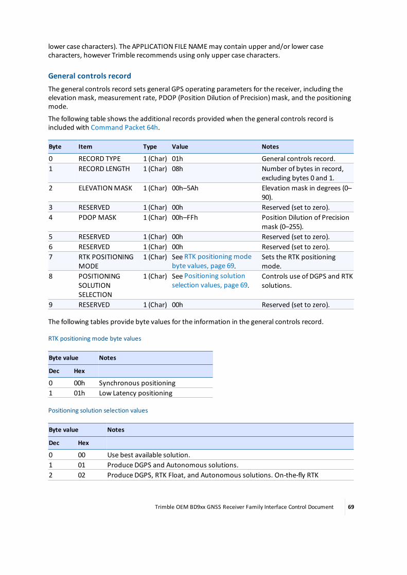
lower case characters). The APPLICATION FILE NAMEmay contain upper and/or lower casecharacters, however Trimble recommends using only upper case characters.
General controls recordThe general controls record sets general GPS operating parameters for the receiver, including theelevation mask, measurement rate, PDOP (Position Dilution of Precision)mask, and the positioningmode.
The following table shows the additional records provided when the general controls record isincluded with Command Packet 64h.
Byte Item Type Value Notes
0 RECORD TYPE 1 (Char) 01h General controls record.1 RECORD LENGTH 1 (Char) 08h Number of bytes in record,
excluding bytes 0 and 1.2 ELEVATIONMASK 1 (Char) 00h–5Ah Elevation mask in degrees (0–
90).3 RESERVED 1 (Char) 00h Reserved (set to zero).4 PDOP MASK 1 (Char) 00h–FFh Position Dilution of Precision
mask (0–255).5 RESERVED 1 (Char) 00h Reserved (set to zero).6 RESERVED 1 (Char) 00h Reserved (set to zero).7 RTK POSITIONING
MODE1 (Char) See RTK positioning mode
byte values, page 69.Sets the RTK positioningmode.
8 POSITIONINGSOLUTIONSELECTION
1 (Char) See Positioning solutionselection values, page 69.
Controls use of DGPS and RTKsolutions.
9 RESERVED 1 (Char) 00h Reserved (set to zero).
The following tables provide byte values for the information in the general controls record.
RTK positioning mode byte values
Byte value Notes
Dec Hex
0 00h Synchronous positioning1 01h Low Latency positioning
Positioning solution selection values
Byte value Notes
Dec Hex
0 00 Use best available solution.1 01 Produce DGPS and Autonomous solutions.2 02 Produce DGPS, RTK Float, and Autonomous solutions. On-the-fly RTK
Trimble OEM BD9xx GNSS Receiver Family Interface Control Document 69

Byte value Notes
Dec Hex
initialization is disabled, therefore no RTK Fix solutions are generated.3 03 Produce RTK Fix, DGPS, and Autonomous solutions (no RTK Float solutions).
Serial port baud/format recordThe serial port baud rate/format record sets communication parameters for the serial ports.Individual serial ports are identified within the records by the serial port index number.
The following table shows the additional records provided when the serial port baud rate/formatrecord is included with Command Packet 64h.
Byte Item Type Value Notes
0 RECORDTYPE
1 (Char) 02h Serial Port Baud Rate/Format Record.
1 RECORDLENGTH
1 (Char) 04h Number of bytes in the record, excluding bytes 0and 1.
2 SERIALPORTINDEX
1 (Char) 00h–03h The number of the serial port to configure.
3 BAUDRATE
1 (Char) See Baud rate bytevalues, page 70.
Data transmission rate.
4 PARITY 1 (Char) See Parity bytevalues, page 71.
Sets the parity of data transmitted through theport. The eight data bits and one stop bit arealways used, regardless of the parity selection.
5 FLOWCONTROL
1 (Char) See Flow controlbyte values, page71.
Flow control.
The following tables provide byte values for the information in the serial port baud/format record.
Baud rate byte values
Byte value Notes
Dec Hex
0 00h 9600 baud1 01h 2400 baud2 02h 4800 baud3 03h 9600 baud4 04h 19.2K baud5 05h 38.4K baud (default)6 06h 57.6K baud7 07h 115.2K baud
Trimble OEM BD9xx GNSS Receiver Family Interface Control Document 70

Byte value Notes
Dec Hex
8 08h 300 baud9 09h 600 baud10 0Ah 1200 baud11 0Bh 230,000 baud12 0Ch 460,000 baud
Parity byte values
Byte value Notes
Dec Hex
0 00h No Parity (10-bit format)1 01h Odd Parity (11-bit format)2 02h Even Parity (11-bit format)
Flow control byte values
Byte value Notes
Dec Hex
0 00h None1 01h CTS
Reference (base) station recordThe reference station record is an optional record that provides LLA (Latitude, Longitude, Altitude)coordinates for the reference station (base station).
The following table shows the additional records provided when the reference station record isincluded with Command Packet 64h.
Byte Item Type Value Notes
0 RECORD TYPE 1 (Char) 03h Reference Station Record.1 RECORD LENGTH 1 (Char) 25h Data bytes in the record, excluding bytes
0 and 1.2 FLAG 1 (Char) 00h Reserved (set to zero).3 NODE INDEX 1 (Char) 00h Reserved (set to zero).4–11 STATIONNAME 8 (Char) ASCII text Eight-character reference station
description.12–19 REFERENCE LATITUDE 8 (Double)Radians Latitude of reference station, ± π/2.20–27 REFERENCE
LONGITUDE8 (Double)Radians Longitude of reference station, ± π.
28–35 REFERENCE ALTITUDE 8 (Double)Meters Altitude of reference station, –9999.999 ≤h ≤ +9999.999.
Trimble OEM BD9xx GNSS Receiver Family Interface Control Document 71

Byte Item Type Value Notes
36–37 RTCM v2.x STATION ID 2 (Short) 0000h–03FFh Reference Station ID for RTCM v2.xoutput.
38 CMR STATION 1 (Char) 00h–1Fh Reference Station ID for CMR output.
The following bytes may also be included in this message, but are not required:
Byte Item Type Value Notes
39 FRAME CHAR 1 (Char) 40h Indicates that bytes 39-88 contain data.40 STATIONNAME
INDICATOR1 (Char) 41h Indicates that the Station ID (point ID) is
present.41–60 STATIONNAME 20 (Char) Up to 20 ASCII
characters,space-paddedas required
Transfer all 20 characters of the basepoint's ID to the rover station(CMR/RETBASE transfers only 4 of thecharacters in the STATION ID field).
61 STATION CODEINDICATOR
1 (Char) 42h Indicates that the Feature Code field ispresent.
62–77 STATION CODE 16 (Char) Up to 16 ASCIIcharacters,space-paddedas required
Transfer all 16 characters of the basepoint's feature code to the rover station.
78 FLAG 1 (Char) 20h Reserved (set to 0x20).79 FLAG 1 (Char) 20h Reserved (set to 0x20).80 FLAG 1 (Char) 20h Reserved (set to 0x20).81 FLAG 1 (Char) 20h Reserved (set to 0x20).82 FLAG 1 (Char) 20h Reserved (set to 0x20).83 FLAG 1 (Char) 20h Reserved (set to 0x20).84 FLAG 1 (Char) 20h Reserved (set to 0x20).85 FLAG 1 (Char) 20h Reserved (set to 0x20).86 FLAG 1 (Char) 20h Reserved (set to 0x20).87 FLAG 1 (Char) 20h Reserved (set to 0x20).88 FRAME CHAR 1 (Char) 40h Terminates string.89–90 RTCM v3.x STATION
ID2 (Short) 0000h–0FFFh Reference Station ID for RTCM v3.x
output.
GPS SV enable/disable recordThe GPS SV enable/disable record is used to enable or disable a selection of the 32 GPS satellites. Bydefault, the receiver is configured to use all satellites that are in good health. This record is useful forenabling satellites that are not in good health. Once enabled, the health condition of the satellite(s)are ignored, and the GPS signal transmissions from the satellite(s) are considered when computingposition solutions.
Trimble OEM BD9xx GNSS Receiver Family Interface Control Document 72

The following table shows the additional records provided when the GPS SV enable/disable record isincluded with Command Packet 64h.
Byte Item Type Value Notes
0 RECORD TYPE 1(Char)
06h SV Enable/Disable Record.
1 RECORD LENGTH1(Char)
20h Number of bytes in record, excluding bytes 0and 1.
2–33 SVENABLE/DISABLESTATES
32(Chars)
See GPS SVenable/disablestates flag values,page 73.
Array of Enable/Disable flags for the 32 SVs.The first byte sets the requiredEnable/Disable status of SV1, the secondsets the status of SV2, etc.
The following table provides byte values for the information in the SV enable/disable record.
GPS SV enable/disable states flag values
Byte value Notes
Dec Hex
0 00h Heed health (default)1 01h Disable the satellite2 02h Enable the satellite regardless of whether the satellite is in
good or bad health
GLONASS SV enable/disable recordThe GLONASS SV enable/disable record is used to enable or disable a selection of the 24 GLONASSsatellites. By default, the receiver is configured to use all satellites that are in good health. Thisrecord is useful for enabling satellites that are not in good health. Once enabled, the healthcondition of the satellite(s) are ignored, and the GLONASS signal transmissions from the satellite(s)are considered when computing position solutions.
The following table shows the additional records provided when the GLONASS SV enable/disablerecord is included with Command Packet 64h.
Byte Item Type Value Notes
0 RECORD TYPE 1(Char)
37h GLONASS SV Enable/Disable Record.
1 RECORD LENGTH1(Char)
18h Number of bytes in record, excluding bytes0 and 1.
2–25 GLONASS SVENABLE/DISABLESTATES
24(Chars)
See GLONASS SVenable/disablestates flag values,page 74.
Array of Enable/Disable flags for the 24 SVs.The first byte sets the requiredEnable/Disable status of SV1, the secondsets the status of SV2, etc.
Trimble OEM BD9xx GNSS Receiver Family Interface Control Document 73

The following table provides byte values for the information in the GLONASS SV enable/disablerecord.
GLONASS SV enable/disable states flag values
Byte value Notes
Dec Hex
0 00h Heed health (default)1 01h Disable the satellite2 02h Enable the satellite regardless of whether the satellite is in
good or bad health
QZSS SV enable/disable recordThe QZSS SV enable/disable record is used to enable or disable a selection of the 5 QZSS satellites.By default, the receiver is configured to use all satellites that are in good health. This record is usefulfor enabling satellites that are not in good health. Once enabled, the health condition of the satellite(s) are ignored, and the QZSS signal transmissions from the satellite(s) are considered whencomputing position solutions.
The following table shows the additional records provided when the QZSS SV enable/disable recordis included with Command Packet 64h.
Byte Item Type Value Notes
0 RECORD TYPE 1(Char)
5Fh QZSS SV Enable/Disable Record.
1 RECORD LENGTH1(Char)
05h Number of bytes in record, excluding bytes0 and 1.
2–6 QZSS SVENABLE/DISABLESTATES
5(Chars)
See QZSS SVenable/disablestates flag values,page 74.
Array of Enable/Disable flags for the 5 SVs.The first byte sets the requiredEnable/Disable status of SV1, the secondsets the status of SV2, etc.
The following table provides byte values for the information in the QZSS SV enable/disable record.
QZSS SV enable/disable states flag values
Byte value Notes
Dec Hex
0 00h Heed health (default)1 01h Disable the satellite2 02h Enable the satellite regardless of whether the satellite is in
good or bad health
Trimble OEM BD9xx GNSS Receiver Family Interface Control Document 74

Galileo SV enable/disable recordThe Galileo SV enable/disable record is used to enable or disable a selection of the 52 Galileosatellites. By default, the receiver is configured to use all satellites that are in good health. Thisrecord is useful for enabling satellites that are not in good health. Once enabled, the healthcondition of the satellite(s) are ignored, and the Galileo signal transmissions from the satellite(s) areconsidered when computing position solutions.
The following table shows the additional records provided when the Galileo SV enable/disablerecord is included with Command Packet 64h.
Byte Item Type Value Notes
0 RECORD TYPE 1(Char)
4Fh Galileo SV Enable/Disable Record.
1 RECORD LENGTH1(Char)
34h Number of bytes in record, excluding bytes0 and 1.
2–53 SVENABLE/DISABLESTATES
52(Chars)
See Galileo SVenable/disablestates flag values,page 75.
Array of Enable/Disable flags for the 52 SVs.The first byte sets the requiredEnable/Disable status of SV1, the secondsets the status of SV2, etc.
The following table provides byte values for the information in the Galileo SV enable/disable record.
Galileo SV enable/disable states flag values
Byte value Notes
Dec Hex
0 00h Heed health (default)1 01h Disable the satellite2 02h Enable the satellite regardless of whether the satellite is in
good or bad health
BeiDou SV enable/disable recordThe BeiDou SV enable/disable record is used to enable or disable a selection of the 30 BeiDousatellites. By default, the receiver is configured to use all satellites that are in good health. Thisrecord is useful for enabling satellites that are not in good health. Once enabled, the healthcondition of the satellite(s) are ignored, and the BeiDou signal transmissions from the satellite(s) areconsidered when computing position solutions.
The following table shows the additional records provided when the BeiDou SV enable/disablerecord is included with Command Packet 64h.
Byte Item Type Value Notes
0 RECORD TYPE 1(Char)
50h SV Enable/Disable Record.
1 RECORD LENGTH1 1Eh Number of bytes in record, excluding bytes
Trimble OEM BD9xx GNSS Receiver Family Interface Control Document 75

Byte Item Type Value Notes
(Char) 0 and 1.2–31 SV
ENABLE/DISABLESTATES
30(Chars)
See BeiDou SVenable/disablestates flag values,page 76.
Array of Enable/Disable flags for the 30 SVs.The first byte sets the requiredEnable/Disable status of SV1, the secondsets the status of SV2, etc.
The following table provides byte values for the information in the BeiDou SV enable/disable record.
BeiDou SV enable/disable states flag values
Byte value Notes
Dec Hex
0 00h Heed health (default)1 01h Disable the satellite2 02h Enable the satellite regardless of whether the satellite is in
good or bad health
SBAS SV enable/disable recordThe SBAS SV enable/disable record is used to enable or disable a selection of the SBAS satellites. Bydefault, the receiver is configured to use all currently available satellites that are in good health. Thisrecord is useful for enabling satellites that are not in good health. Once enabled, the healthcondition of the satellite(s) are ignored, and the SBAS signal transmissions from the satellite(s) areconsidered when computing position solutions.
The following table shows the additional records provided when the SBAS SV enable/disable recordis included with Command Packet 64h.
Byte Item Type Value Notes
0 RECORD TYPE 1(Char)
16h SBAS SV Enable/Disable Record.
1 RECORD LENGTH 1(Char)
18h Number of bytes in record, excluding bytes 0and 1.
2 SBAS MODE 1(Char)
See SBASmode values,page 77.
Enable/disable the use of SBAS for positioning.
3 OBSOLETE 1(Char)
00h Reserved
4 OBSOLETE 1(Char)
00h Reserved
5 OBSOLETE 1(Char)
00h Reserved
6 OBSOLETE 1(Char)
00h Reserved
Trimble OEM BD9xx GNSS Receiver Family Interface Control Document 76

Byte Item Type Value Notes
7–25 SBAS SVENABLE/DISABLESTATES
19(Chars)
See SBAS SVmask values,page 77.
Array of Enable/Disable flags for the 19 SVs. Thefirst byte sets the required Enable/Disablestatus of SV1, the second sets the status of SV2,etc.
The length of this message will be expanded in the future as SBAS SV PRN numbers are assigned tovalues higher than 138. See SBAS SVs available, page 77.
The following table provides byte values for the information in the SBAS SV enable/disable record.
SBAS mode values
Byte value Notes
Dec Hex
0 00h Off1 01h Reserved2 02h Track SBAS but do not use corrections3 03h Track and use SBAS corrections
SBAS SV mask values
Byte value Notes
Dec Hex
0 00h Disabled1 01h Enabled and heed health2 02h Use even if unhealthy3 03h Enable this SV if it can be used in the current location (Auto-
Enable)
SBAS SVs available
Note – This table gives the PRNs of the SBAS SVs available as of August 2013.
PRN Satellite
120 EGNOS – AOR-E121122123124 EGNOS – ARTEMIS125126 EGNOS – IND-W127 GAGAN – GSAT 8128 GAGAN
Trimble OEM BD9xx GNSS Receiver Family Interface Control Document 77

PRN Satellite
129 MSAS-1130131132133 WAAS – INMARSAT 4-F3134135 WAAS – GALAXY XV136 EGNOS - SES-5137 MSAS-2138 WAAS – ANIK F1R139140 SDCM - LUCH-5A141142143144145146147148149150151152153154155156157158
Output message recordThe output message record selects the outputs for a specified serial port, the frequency ofmessagetransmissions, the integer second offset from the scheduled output rate, and output-specific flags.Bytes 0 through 5 are included in all records, regardless of the output message type. The remainingbytes in the record are dependent on the output message type.
The following table shows the additional records provided when the output message record isincluded with Command Packet 64h.
Byte Item Type Value Notes
0 RECORD TYPE 1 (Char) 07h Output Message Record.
Trimble OEM BD9xx GNSS Receiver Family Interface Control Document 78

Byte Item Type Value Notes
1 RECORDLENGTH
1 (Char) 04h, 05h or 06h Number of bytes in the record, excludingbytes 0 and 1. The number of bytes isdependent on the number of outputspecific flags.
2 OUTPUTMESSAGETYPE
1 (Char) See Output messagetype byte values, page81.
Type ofmessage or packet.
3 PORT INDEX 1 (Char) See Port numbervalues, page 82.
The port number for RS-232 Serial, USB orEthernet ports is 0-based.
4 FREQUENCY 1 (Char) See Frequency bytevalues, page 83.
Frequency ofmessage transmissions.
Note – For RTCM version 3 this byte isignored (see the RTCM and RT17/RT27 ratevalues, page 85 bytes 10 & 11), set to 01h.
5 OFFSET 1 (Char) 00h–FFh Integer second offset (0–255 seconds)from scheduled output rate. (Only validwhen frequency is < 1 Hz or >1 second.)
If "Output Message Type" is GSOF:
Byte Item Type Value Notes
6 GSOF SUBMESSAGETYPE
1 (Char) See GSOF messagerecord type, page 83.
GSOF message number.
7 OFFSET 1 (Char) 0–255 Integer second offset fromscheduled frequency.
If "Output Message Type" is CMR:
Byte Item Type Value Notes
6 CMRMESSAGETYPE FLAGS
1 (Char) See Output messagerecord, page 78.
CMRmessage types:
0: Standard CMR+
1: High speed CMR (5, 10, or 20 Hz)
2: Standard CMR (compatible with Trimble4000 receivers)
3: sCMRx7 RESERVED 1 (Char) 00h Set to zero.8–9 BANDWIDTH
LIMIT2 (Short) If non-zero, then CMR+ or RTCM version
3.0 output will be limited to the specifiednumber of bytes/sec. For anything butCMR+ and RTCM version 3.0, this limit isignored.
If "Output Message Type" is RTCM:
Trimble OEM BD9xx GNSS Receiver Family Interface Control Document 79

Byte Item Type Value Notes
6 RTCM FLAGS 1 (Char) See RTCM flag values,page 85.
Bit settings for RTCM output flags.
7 RESERVED 1 (Char) 00h Set to zero.8–9 BANDWIDTH
LIMIT2 (Short) If non-zero, then CMR+ or RTCM version
3.0 output will be limited to the specifiednumber of bytes/sec. For anything butCMR+ and RTCM version 3.0, this limit isignored.
10 RATE 1 1 (Char) See RTCM andRT17/RT27 rate values,page 85.
If RTCM version 2:
0xf0 : Controls Type 1 record rate.
0x0f : Controls Type 31 record rate.
Note – if the “Advanced RTCMOutput" optionis installed the type rate can be set. The defaultvalue is 2Fh. The type 31 rate can be set with orwithout the “Advanced RTCMOutput" option isinstalled.
If RTCM version 3:
0xf0 : Controls Type 1004 record rate.
0x0f : Controls Type 1012 record rate.
Note – if the “Advanced RTCMOutput" optionis installed this byte can be set, when notinstalled the only valid value is 22h.
11 RATE 2 1 (Char) See RTCM andRT17/RT27 rate values,page 85.
If RTCM version 2:
0xf0 : Controls Type 3 record rate.
0x0f : Controls Type 32 record rate.
Note – if the “Advanced RTCMOutput" optionis installed this byte can be set, when notinstalled the only valid value is 5Fh.
If RTCM version 3:
0xf0 : Controls Type 1019 record rate.
0x0f : Controls Type 1020 record rate.
Note – if the “Advanced RTCMOutput" optionis installed this byte can be set, when notinstalled the only valid value is FFh.
If "Output Message Type" is RT17/RT27:
Byte Item Type Value Notes
6 REAL-TIMEMESSAGE
1 (Char) See Real-timemessageflag 1 values, page 84.
RT17/RT27 flag 1.
Trimble OEM BD9xx GNSS Receiver Family Interface Control Document 80

Byte Item Type Value Notes
FLAG 17 REAL-TIME
MESSAGEFLAG 2
1 (Char) See Real-timemessageflag 2 values, page 84.
RT17/RT27 flag 2.
8–9 RESERVED 2 (Char) 0000h Reserved (set to zero).10 RATE 1 1 (Char) See RTCM and
RT17/RT27 rate values,page 85.
0xf0 : Controls GLONASS Ephemeris rate.
0x0f : Controls GPS Ephemeris rate.
Used in conjunction with RT17/RT27 flag1, bit 2. RT17/RT27 flag 1, bit 2 is on ifboth GPS & GLONASS ephemeris are on.
10 RATE 2 1 (Char) See RTCM andRT17/RT27 rate values,page 85.
0xf0 : Controls QZSS Ephemeris rate.
0x0f : Controls Galileo Ephemeris rate.
10 RATE 3 1 (Char) See RTCM andRT17/RT27 rate values,page 85.
0xf0 : Controls Almanac rate.
0x0f : Controls BeiDou Ephemeris rate.
The following tables provide byte values for the information in the output message record.
Output message type byte values
Bytevalue
Notes
0xFF Turn off all outputs on all ports. Frequency must also be 'Off' for thisto work.
0 Turn off all outputs on the given port only. Frequency must be 'Off'for this to work
1 Not used.2 CMR Output3 RTCM Output4 RT17/RT27 Output5 Not used.6 NMEA_GGA7 NMEA_GGK8 NMEA_ZDA9 Reserved10 GSOF11 1PPS12 NMEA_VTG13 NMEA_GST14 NMEA_PJK15 NMEA_PJT
Trimble OEM BD9xx GNSS Receiver Family Interface Control Document 81

Bytevalue
Notes
16 NMEA_VGK17 NMEA_VHD18 NMEA_GSV19 NMEA_TSN20 NMEA_TSS21 NMEA_PRC22 NMEA_REF23 NMEA_GGK_SYNC24 J1939_VehPos25 J1939_Time26 J1939_VehSpd27 J1939_ImpPos28 J1939_ImpSpd29 NMEA_AVR30 Reserved31 NMEA_HDT32 NMEA_ROT33 NMEA_ADV34 NMEA_PIO35 NMEA_BETA36 Reserved37 NMEA_VRSGGA38 NMEA_GSA39 Binex40 NMEA_RMC41 NMEA_BPQ42 Reserved43 Reserved44 NMEA_GLL45 NMEA_GRS46 Reserved47 NMEA_LDG
Port number values
1-basedPort ID
0-basedPort ID
Name Notes
1 0 Serial port 12 1 Serial port 23 2 Serial port 34 3 Serial port 4 On receivers with a 4th serial port
Trimble OEM BD9xx GNSS Receiver Family Interface Control Document 82
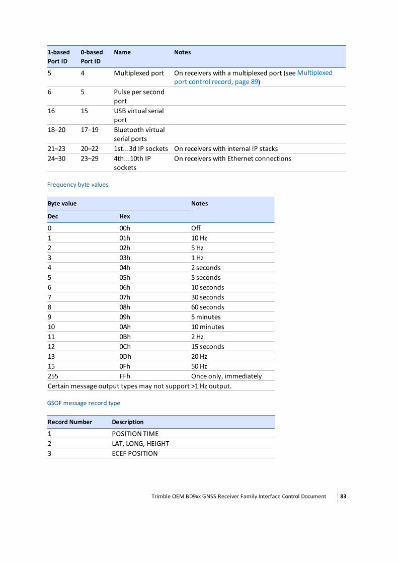
1-basedPort ID
0-basedPort ID
Name Notes
5 4 Multiplexed port On receivers with a multiplexed port (seeMultiplexedport control record, page 89)
6 5 Pulse per secondport
16 15 USB virtual serialport
18–20 17–19 Bluetooth virtualserial ports
21–23 20–22 1st...3d IP sockets On receivers with internal IP stacks24–30 23–29 4th...10th IP
socketsOn receivers with Ethernet connections
Frequency byte values
Byte value Notes
Dec Hex
0 00h Off1 01h 10 Hz2 02h 5 Hz3 03h 1 Hz4 04h 2 seconds5 05h 5 seconds6 06h 10 seconds7 07h 30 seconds8 08h 60 seconds9 09h 5minutes10 0Ah 10minutes11 0Bh 2 Hz12 0Ch 15 seconds13 0Dh 20 Hz15 0Fh 50 Hz255 FFh Once only, immediatelyCertain message output types may not support >1 Hz output.
GSOF message record type
Record Number Description
1 POSITION TIME2 LAT, LONG, HEIGHT3 ECEF POSITION
Trimble OEM BD9xx GNSS Receiver Family Interface Control Document 83

Record Number Description
4 LOCAL DATUM POSITION5 LOCAL ZONE POSITION6 ECEF DELTA7 TANGENT PLANE DELTA8 VELOCITY DATA9 PDOP INFO10 CLOCK INFO11 POSITION VCV INFO12 POSITION SIGMA INFO13 SV BRIEF INFO14 SV DETAILED INFO15 RECEIVER SERIAL NUMBER16 CURRENT TIME26 POSITION TIME UTC27 ALTITUDE INFO+1
41 BASE POSITIONAND QUALITY INDICATOR33 ALL SV BRIEF INFO34 ALL SV DETAILED INFO35 RECEIVED BASE INFO
Real-time message flag 1 values
Value Notes
0 (lsb) Compact Format – 0: Disabled 1: Enabled1 RT (Real-Time) Enhancements – 0: Disabled 1: Enabled2 Streamed Ephemeris – 0: Disabled 1: Enabled3 Streamed Position – 0: Disabled 1: Enabled4 Position Only – 0: Disabled 1: Enabled5 Reserved (set to zero)6 Reserved (set to zero)7 (msb) Reserved (set to zero)
Real-time message flag 2 values
Value Notes
0 (lsb) EnableMulti-System Support (RT27) – 0: Disabled 1: Enabled1 Enable Phase Smoothing – 0: Disabled 1: Enabled2 Enable Pseudorange Smoothing – 0: Disabled 1: Enabled3 Reserved (set to zero)4 Include Doppler – 0: Disabled 1: Enabled
1If flags are invalid, the record is not applied. (However, the application file may be accepted.)
Trimble OEM BD9xx GNSS Receiver Family Interface Control Document 84

Value Notes
5 Reserved (set to zero)6 Reserved (set to zero)7 (msb) Reserved (set to zero)
RTCM flag values
Value Notes
0 Output RTK Packets (type 3, 18, 19)1 Output DGPS Packets (type 3, 1)2 Output DGPS RTCM packets (Type 3, 9)3 Not set: Output RTCM v2.1
Set: Output RTCM v2.24 Not set: No Output
Set: Output RTCM v2.35 Not set: No Output
Set: Output RTCM v3.0
Setting bit 5 overrides bits 3 and 4. Bit 2 cannot be set when bit 5 isset because that is rejected as an error.
RTCM and RT17/RT27 rate values
Value Meaning
0 (RT17/RT27: output as available)1 100milliseconds2 1 second3 2 seconds4 5 seconds5 10 seconds6 30 seconds7 60 seconds8 120 seconds9 300 seconds or 5minutes10 600 seconds or 10minutes11 900 seconds or 15minutes12 1800 seconds or 20minutes13 3600 seconds or 60minutes14 7200 seconds or 120minutes15 Off
Trimble OEM BD9xx GNSS Receiver Family Interface Control Document 85
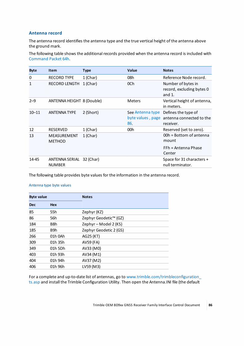
Antenna recordThe antenna record identifies the antenna type and the true vertical height of the antenna abovethe ground mark.
The following table shows the additional records provided when the antenna record is included withCommand Packet 64h.
Byte Item Type Value Notes
0 RECORD TYPE 1 (Char) 08h Reference Node record.1 RECORD LENGTH 1 (Char) 0Ch Number of bytes in
record, excluding bytes 0and 1.
2–9 ANTENNAHEIGHT 8 (Double) Meters Vertical height of antenna,in meters.
10–11 ANTENNA TYPE 2 (Short) See Antenna typebyte values , page86.
Defines the type ofantenna connected to thereceiver.
12 RESERVED 1 (Char) 00h Reserved (set to zero).13 MEASUREMENT
METHOD1 (Char) 00h = Bottom of antenna
mount
FFh = Antenna PhaseCenter
14-45 ANTENNA SERIALNUMBER
32 (Char) Space for 31 characters +null terminator.
The following table provides byte values for the information in the antenna record.
Antenna type byte values
Byte value Notes
Dec Hex
85 55h Zephyr (KZ)86 56h Zephyr Geodetic™ (GZ)184 B8h Zephyr –Model 2 (KS)185 B9h Zephyr Geodetic 2 (GS)266 01h 0Ah AG25 (KT)309 01h 35h AV59 (FA)349 01h 5Dh AV33 (M0)403 01h 93h AV34 (M1)404 01h 94h AV37 (M2)406 01h 96h LV59 (M3)
For a complete and up-to-date list of antennas, go to www.trimble.com/trimbleconfiguration_ts.asp and install the Trimble Configuration Utility. Then open the Antenna.INI file (the default
Trimble OEM BD9xx GNSS Receiver Family Interface Control Document 86

location is C:\Program Files\Common Files\Trimble\Config\antenna.ini) with an ASCII viewer to findantennas by name and their antenna type value.
Device control recordThe device control record contains configuration parameters for controlling some external devicesand the operation of some receiver options. The number of bytes contained in the record and thelength of the record are determined by the device type entry.
The following table shows the additional records provided when the device type record is includedwith Command Packet 64h.
Devicetype
Byte Item Type Value Notes
All 0 RECORD TYPE1 (Char) 09h Device Control record.1 RECORD
LENGTH1 (Char) 02h or 0Dh Number of bytes in record,
excluding bytes 0 and 1.2 DEVICE TYPE 1 (Char) See Device type byte
values, page 87.Type of device.
1 PPSOutputonly
3 1 PPSCONTROL
1 (Char) See 1 PPS control bytevalues, page 88.
Enables or disables 1 PPS output;when byte 2 is set to 02h.
EventMarkeronly
3 EVENTCONTROL
1 (Char) See Event control bytevalues, page 88.
Enables or disables event marker;when byte 2 is set to 01h.
4 EVENTTRIGGERSENSE
1 (Char) See Trigger controlbyte values, page 88.
The following tables provide byte values for the information in the device control record.
Device type byte values
Byte value Notes
Dec Hex
0 00h Reserved1 01h Event Marker 12 02h 1 PPS (Pulse per second) output3 03h Reserved4 04h Reserved5 05h Reserved6 06h Reserved7 07h Reserved
Trimble OEM BD9xx GNSS Receiver Family Interface Control Document 87

1 PPS control byte values
Byte value Notes
Dec Hex
0 00h 1 PPS output is off1 01h 1 PPS output is on
Event control byte values
Byte value Notes
Dec Hex
0 00h Event Marker 1 is disabled1 01h Event Marker 1 is enabled
Trigger control byte values
Byte value Notes
Dec Hex
0 00h Positive Trigger Edge1 01h Negative Trigger Edge
Static/kinematic recordThe static/kinematic record identifies the antenna type and the true vertical height of the antennaabove the ground mark.
The following table shows the additional records provided when the static/kinematic record isincluded with Command Packet 64h.
Byte Item Type Value Notes
0 RECORD TYPE 1(Char)
0Ah Static/Kinematic record.
1 RECORD LENGTH 1(Char)
01h Number of bytes in record, excludingbytes 0 and 1.
2 STATIC/KINEMATICMODE
1(Char)
See Static/kinematic bytevalues, page 88.
Configures receiver for static orkinematic operation.
The following table provides byte values for the information in the static/kinematic record.
Static/kinematic byte values
Byte value Notes
Dec Hex
0 00h Kinematic1 01h Static2–255 02h–FFh Reserved
Trimble OEM BD9xx GNSS Receiver Family Interface Control Document 88

Multiplexed port control recordThemultiplexed port control record identifies which of themultiplexed ports is active.
The following table shows the additional records provided when the output message record isincluded with Command Packet 64h.
Byte Item Type Value Notes
0 RECORD TYPE 1 (Char) 53h Multiplexed port control record.1 RECORD
LENGTH1 (Char) 01h Number of bytes in the record,
excluding bytes 0 and 1.2 SELECTEDMUX
PORT1 (Char) See Selected MUX port
type byte values, page 89.Type ofmessage or packet.
The following table provides byte values for the information in themultiplexed port control record.
Selected MUX port type byte values
Byte value Notes
0 None1 CAN12 Serial (COM3 on the BD970 and BD982)3 Event 24 PPS
Vector antenna recordThe vector antenna record identifies the antenna type of the vector antenna.
The following table shows the additional records provided when the antenna record is included withCommand Packet 64h.
Byte Item Type Value Notes
0 RECORD TYPE 1 (Char) 4Eh Vector Antenna Record.1 RECORD LENGTH 1 (Char) 32h Number of bytes in the record,
excluding bytes 0 and 1.2 VERSION 1 (Char) (Set to zero)3 RESERVED 1 (Char) Reserved (set to zero).4–11 ANTENNAHEIGHT 8
(Double)Meters Vertical height of antenna, in
meters. Range: 0.0 - +8.0meters.12–43 ANTENNA SERIAL
NUMBER32 (Char) 00h–FFh Space for 31 characters + null
terminator.44–45 ANTENNA TYPE 2 (Short) See Antenna type byte
values.Defines the type of antennaconnected to the receiver.
46 MEASUREMENTMETHOD
1 (Char) 00h = Bottom of antenna mount FFh= Antenna Phase Center
47–51 RESERVED 5 (Char) Reserved (set to zeros).
Trimble OEM BD9xx GNSS Receiver Family Interface Control Document 89
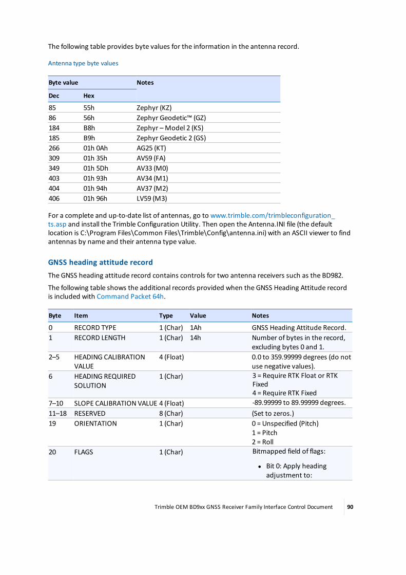
The following table provides byte values for the information in the antenna record.
Antenna type byte values
Byte value Notes
Dec Hex
85 55h Zephyr (KZ)86 56h Zephyr Geodetic™ (GZ)184 B8h Zephyr –Model 2 (KS)185 B9h Zephyr Geodetic 2 (GS)266 01h 0Ah AG25 (KT)309 01h 35h AV59 (FA)349 01h 5Dh AV33 (M0)403 01h 93h AV34 (M1)404 01h 94h AV37 (M2)406 01h 96h LV59 (M3)
For a complete and up-to-date list of antennas, go to www.trimble.com/trimbleconfiguration_ts.asp and install the Trimble Configuration Utility. Then open the Antenna.INI file (the defaultlocation is C:\Program Files\Common Files\Trimble\Config\antenna.ini) with an ASCII viewer to findantennas by name and their antenna type value.
GNSS heading attitude recordThe GNSS heading attitude record contains controls for two antenna receivers such as the BD982.
The following table shows the additional records provided when the GNSS Heading Attitude recordis included with Command Packet 64h.
Byte Item Type Value Notes
0 RECORD TYPE 1 (Char) 1Ah GNSS Heading Attitude Record.1 RECORD LENGTH 1 (Char) 14h Number of bytes in the record,
excluding bytes 0 and 1.2–5 HEADING CALIBRATION
VALUE4 (Float) 0.0 to 359.99999 degrees (do not
use negative values).6 HEADING REQUIRED
SOLUTION1 (Char) 3 = Require RTK Float or RTK
Fixed4 = Require RTK Fixed
7–10 SLOPE CALIBRATIONVALUE 4 (Float) -89.99999 to 89.99999 degrees.11–18 RESERVED 8 (Char) (Set to zeros.)19 ORIENTATION 1 (Char) 0 = Unspecified (Pitch)
1 = Pitch2 = Roll
20 FLAGS 1 (Char) Bitmapped field of flags:
l Bit 0: Apply headingadjustment to:
Trimble OEM BD9xx GNSS Receiver Family Interface Control Document 90
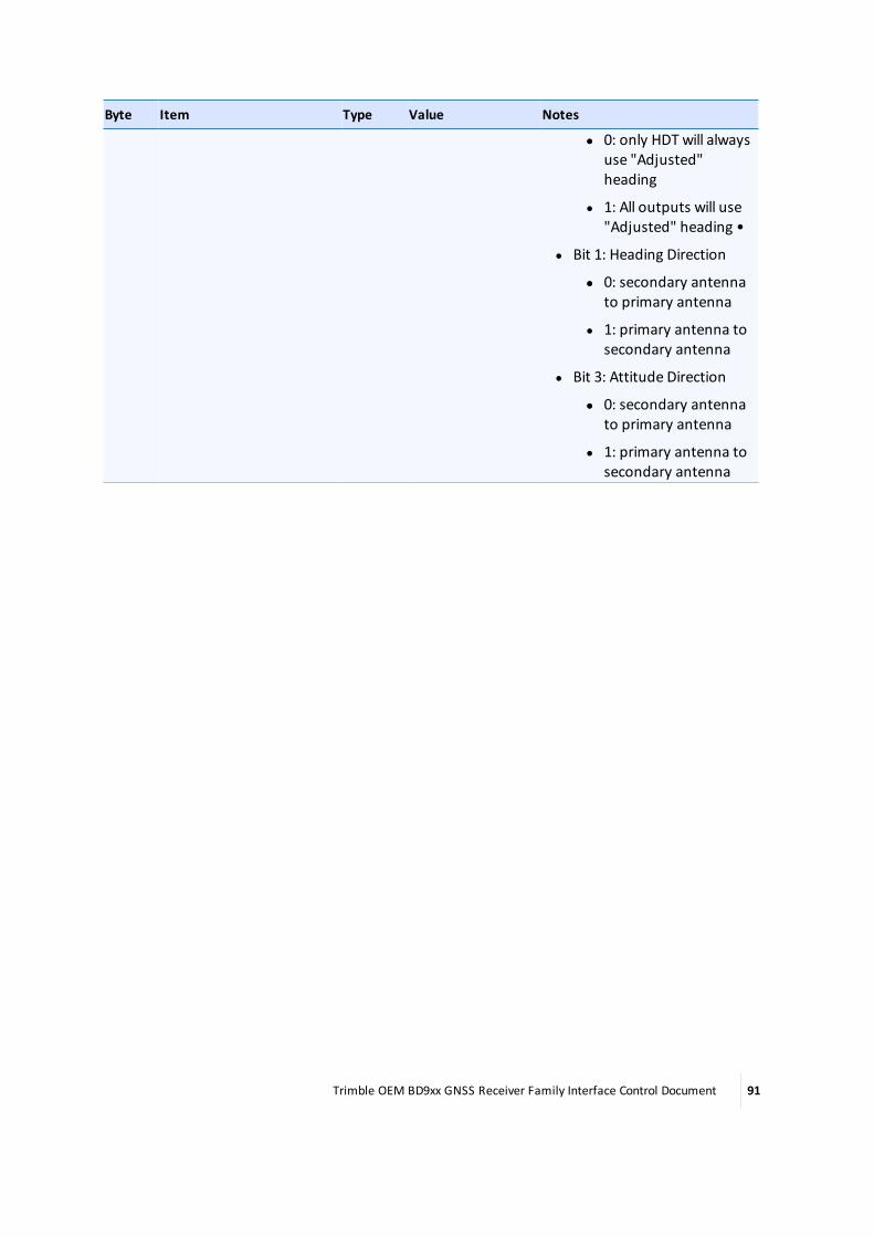
Byte Item Type Value Notes
ll 0: only HDT will alwaysuse "Adjusted"heading
l 1: All outputs will use"Adjusted" heading •
l Bit 1: Heading Direction
ll 0: secondary antennato primary antenna
l 1: primary antenna tosecondary antenna
l Bit 3: Attitude Direction
ll 0: secondary antennato primary antenna
l 1: primary antenna tosecondary antenna
Trimble OEM BD9xx GNSS Receiver Family Interface Control Document 91

Command 65h, GETAPPFILE (Application file request)A specific application file can be downloaded from the receiver by sending the Command Packet65h. If the request is valid, a copy of the application file is downloaded to the remote device inReport Packet 64h.
The receiver can storemultiple application files (including a default application file, containing thefactory default parameter settings) in the application file directory. Each application file is assigned anumber to give the file a unique identity within the directory. The application file containing thefactory default values is assigned a system file index code of zero (0).
The following table shows the packet structure. All data in the packet flows from the data collectorto the receiver. For more information, see Command 64h, APPFILE (Application file record), page 65.
Byte Item Type Value Notes
0 STX 1(Char)
02h Start transmission
1 STATUS 1(Char)
See Receiver statusbyte, page 11.
Receiver status indicator.
2 PACKETTYPE
1(Char)
65h Command Packet Type
3 LENGTH 1(Char)
See Packetstructure, page 11.
Data byte count.
4–5 SYSTEMFILE INDEX
2(Short)
0–n Unique number (ID code) assigned to each of theapplication files stored in the application filedirectory.
6 CHECKSUM 1(Char)
See Packetstructure, page 11.
Checksum value.
7 ETX 1(Char)
03h End transmission
Trimble OEM BD9xx GNSS Receiver Family Interface Control Document 92

Response 64h, APPFILE (Application file record report)Report Packet 64h is sent to the remote device when Command Packet 65h is sent to request aspecific application file. Command Packet 65h requests the application file by System File Index.
For more information about application files and guidelines for using application files to controlremote devices, see Command 64h, APPFILE (Application file record), page 65.
The Application File Record Report format is identical to the format used for Command Packet 64h.For more information, see Packet paging, page 63.
Trimble OEM BD9xx GNSS Receiver Family Interface Control Document 93

Command 66h, GETAFDIR (Application file directory listing)Command Packet 66h is used to request a directory listing of the application files stored in receivermemory. The receiver responds by sending the directory listing in Report Packet 67h.
The following table describes the packet structure.
Byte Item Type Value Notes
0 STX 1 (Char) 02h Start transmission1 STATUS 1 (Char) See Table 3.2, page 13. Receiver status code.2 PACKET TYPE 1 (Char) 66h Command Packet Type3 LENGTH 1 (Char) 0h Data byte count4 CHECKSUM 1 (Char) See Table 3.1, page 12. Checksum value.5 ETX 1 (Char) 03h End transmission
Trimble OEM BD9xx GNSS Receiver Family Interface Control Document 94

Response 67h, RETAFDIR (Directory listing report)Report Packet 67h sends a listing of the application files in the application file directory. The report isrequested with Command Packet 66h.
Report Packet 67h can exceed themaximum data byte limit (248 bytes of data) for RS-232 SerialInterface Specification packets, depending on the number of application files stored in memory.Each application file directory entry occupies 17 bytes. The application file directory block (bytes 8–24) is repeated for every application file stored in directory. At least one application file exists(SYSTEM FILE INDEX number 0, the Default Application File). The receiver can storemultiple user-defined application file records.
Report Packet 67h is divided into subpackets called pages when the data byte limit is exceeded. ThePAGE INDEX and MAXIMUM PAGE INDEX bytes are used to account for the pages included in thereport (0 of 2, 1 of 2, 2 of 2).
The TX BLOCK IDENTIFIER uses a roll-over counter to assign a transaction number to the reportpacket pages. The TX BLOCK IDENTIFIER INDEX number is useful for preventing data mismatcheswhen stream synchronization is lost.
The following table describes the packet structure.
Note – All date and time fields are relative to UTC.
Byte Item Type Value Meaning
0 STX 1 (Char) 02h Start transmission.1 STATUS 1 (Char) See Receiver status
byte, page 11.Receiver status code.
2 PACKET TYPE 1 (Char) 67h Report Packet Type.3 LENGTH 1 (Char) See Packet structure,
page 11.Data byte count.
4 TX BLOCKIDENTIFIER
1 (Char) 00h–FFh Unique number assigned to everyapplication file transfer.
5 PAGE INDEX 1 (Char) 00h–FFh Page index assigned to packet page.6 MAXIMUM
PAGE INDEX1 (Char) 00h–FFh Page index assigned to the last packet
page.7 # APP FILES 1 (Char) 00h–n Number of application files in directory.
First application file directory record. This block is repeated for each application file.8–9 SYSTEM FILE
INDEX2 (Char) See System file index
values, page 96.Record number assigned to the file.
10–17 APP FILENAME
8 (Chars) ASCII text Name of application file (8 ASCIIcharacters).
18 CREATIONYEAR
1 (Char) 00h–FFh Year when file is created. Based on theyears since 1900 (1900 = 00).
19 CREATIONMONTH
1 (Char) 01h–0Ch Month of the year when file is created (1–12).
20 CREATIONDAY 1 (Char) 01h–1Fh Day of themonth when file is created (1–31).
Trimble OEM BD9xx GNSS Receiver Family Interface Control Document 95
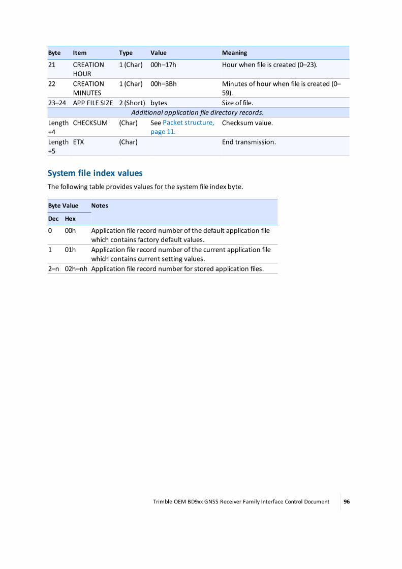
Byte Item Type Value Meaning
21 CREATIONHOUR
1 (Char) 00h–17h Hour when file is created (0–23).
22 CREATIONMINUTES
1 (Char) 00h–3Bh Minutes of hour when file is created (0–59).
23–24 APP FILE SIZE 2 (Short) bytes Size of file.Additional application file directory records.
Length+4
CHECKSUM (Char) See Packet structure,page 11.
Checksum value.
Length+5
ETX (Char) End transmission.
System file index valuesThe following table provides values for the system file index byte.
Byte Value Notes
Dec Hex
0 00h Application file record number of the default application filewhich contains factory default values.
1 01h Application file record number of the current application filewhich contains current setting values.
2–n 02h–nh Application file record number for stored application files.
Trimble OEM BD9xx GNSS Receiver Family Interface Control Document 96

Command 68h, DELAPPFILE (Delete application file data)Command Packet 68h deletes the data for a specified application file. The application file is selectedby specifying the System File Index assigned to the file.
Byte Item Type Value Notes
0 STX 1(Char)
02h Start transmission.
1 STATUS 1(Char)
See Receiver statusbyte, page 11.
Receiver status indicator.
2 PACKETTYPE
1(Char)
68h Command Packet Type.
3 LENGTH 1(Char)
02h Data byte count.
4–5 SYSTEMFILE INDEX
2(Short)
0–n Unique number assigned to each of the applicationfiles stored in the Application File directory.
6 CHECKSUM 1(Char)
See Packetstructure, page 11.
Checksum.
7 ETX 1(Char)
03h End transmission.
Trimble OEM BD9xx GNSS Receiver Family Interface Control Document 97

Command 6Dh, ACTAPPFILE (Activate application file)Command Packet 6Dh is used to activate one of the application files stored in the Application Filedirectory. The application file with the specified System File Index is activated.
Each application file is assigned a System File Index. The application file containing the factorydefault values is assigned a System File Index of zero (0), allowing this command to be used to resetthe receiver to the factory default conditions.
The following table describes the packet structure.
Byte Item Type Value Notes
0 STX 1(Char)
02h Start transmission
1 STATUS 1(Char)
See Receiver statusbyte, page 11.
Receiver status indicator.
2 PACKETTYPE
1(Char)
6Dh Command Packet Type
3 LENGTH 1(Char)
02h Data byte count
4–5 SYSTEMFILE INDEX
2(Short)
0–n Unique number assigned to each of theapplication files stored in the Application Filedirectory
6 CHECKSUM 1(Char)
See Packetstructure, page 11.
Checksum.
7 ETX 1(Char)
03h End transmission
Trimble OEM BD9xx GNSS Receiver Family Interface Control Document 98

Display screen and software interface packets
Command 81h, KEYSIM (Key simulator)Command Packet 81h simulates any front panel key press.
Byte Item Type Value Notes
0 STX 1 (Char) 02h Start transmission1 STATUS 1 (Char) See Receiver status byte, page 11 Receiver status code.2 PACKET TYPE 1 (Char) 81h Command Packet Type3 LENGTH 1 (Char) 01h Data byte count4 KEY ID 1 (Char) See Key ID codes, page 99. Key scan code ID.5 CHECKSUM 1 (Char) See Packet structure, page 11. Checksum values.6 ETX 1 (Char) 03h End transmission
Key ID codesThe following table provides values for the key ID byte.
Scan code Receiver key ASCII character
7Fh [CLEAR] [Del] <del>0Dh [ENTER] [Enter] <carriage return>41h Softkey Choice 1 <A>42h Softkey Choice 2 <B>43h Softkey Choice 3 <C>44h Softkey Choice 4 <D>1Dh [<] —1Ch [>] —30h [0] <0>31h [1] <1>32h [2] <2>33h [3] <3>34h [4] <4>35h [5] <5>36h [6] <6>37h [7] <7>38h [8] <8>39h [9] <9>4Ch [STATUS] <L>4Ah [SESSION] <J>4Bh [SAT{{INFO] <K>4Fh [LOG{{DATA] <O>4Dh [CONTROL] <M>50h [ALPHA] <P>
Trimble OEM BD9xx GNSS Receiver Family Interface Control Document 99

Scan code Receiver key ASCII character
4Eh [MODIFY] <N>1Bh [POWER] —
Trimble OEM BD9xx GNSS Receiver Family Interface Control Document 100

Command 82h, SCRDUMP (Screen dump request)Command Packet 82h has two forms—a command packet and report packet. Both packets areassigned the same hexadecimal code (82h).
Command Packet 82h requests an ASCII representation of a BD9xx simulated display screen. Inresponse, Report Packet 82h sends the data used that is used to display the screen to the remotedevice in ASCII format.
The following table shows the packet structure.
Byte Item Type Value Meaning
0 STX CHAR 02h Start transmission1 STATUS CHAR See Receiver status byte, page 11. Receiver status code2 PACKET TYPE CHAR 82h Command Packet 82h3 LENGTH CHAR 0h Data bytes count4 CHECKSUM CHAR See Packet structure, page 11. Checksum value5 ETX CHAR 03h End transmission
Trimble OEM BD9xx GNSS Receiver Family Interface Control Document 101

Response 82h, SCRDUMP (Screen dump)Report Packet 82h is sent in response to Command Packet 82h. The receiver generates an ASCIIrepresentation (a dump) of a BD9xx display screen, and sends the dump to the remote device inReport Packet 82h.
The following table shows the packet structure.
Byte Item Type Value Notes
0 STX CHAR 02h Start transmission1 STATUS CHAR See Receiver status byte, page 11. Receiver status code.2 PACKET TYPE CHAR 82h Report Packet Type3 LENGTH CHAR A1h Data byte count4–163 ASCII DATA CHARs ASCII data164 CURSOR POSITION CHAR Position of the cursor165 CHECKSUM CHAR See Packet structure, page 11. Checksum value.166 ETX CHAR 03h End transmission
Trimble OEM BD9xx GNSS Receiver Family Interface Control Document 102

Miscellaneous receiver control packets
Command/response AEh, Ethernet configurationThe following table describes the structure of the report packet containing the application file. Alldata in the packet flows from the data collector to the receiver.
Byte Item Type Value Notes
0 STX 1(Char)
02h Start transmission.
1 STATUS 1(Char)
See Receiver status byte,page 11.
Receiver status indicator.
2 PACKETTYPE
1(Char)
AEh Command/Response packet AEh
3 LENGTH 1(Char)
See Packet structure, page11.
Data byte count.
4 SUBTYPE 1(Char)
00h, 01h, 02h, 0Ch, 0Dh,0Eh, 0Fh, 10h
Subtypes can be:
l 00h: Get DHCP and IP Address
l 01h: Response DHCP and IP Address
l 02h: Set DHCP and IP Address
l 0Ch: Get IP Port Summary
l 0Dh: Return IP Port Summary
l 0Eh: Get Individual IP PortConfiguration
l 0Fh: Return Individual IP PortConfiguration
l 10h: Set Individual IP PortConfiguration
CHECKSUM1(Char)
See Packet structure, page11.
Checksum value.
ETX 1(Char)
03h End transmission.
SubtypesThe subtypes are:
l 00h: command sent from the data collector to the receiver this will cause the receiver torespond with the type 01h subtypemessage.
l 01h: response from the receiver giving the DHCP and IP Address status of the unit. For theresponse packets, see Subtype 1: Response DHCP and IP Address, page 104
Trimble OEM BD9xx GNSS Receiver Family Interface Control Document 103

l 02h: command sent from the data collector to the receiver setting the DHCP and IP Addressstatus of the unit. For the structure of the command packet, see Subtype 2: Set DHCP andIP Address, page 104. It must include all fields even if DHCP is enabled (address fields can be setto 00h if DHCP is used).
l 0Ch: command sent from the data collector to the receiver this will cause the receiver torespond with the type 0Dh subtypemessage.
l 0Dh: response from the receiver giving the IP port summary of the unit. For the responsepackets, see Subtype 0Dh: Response IP Port Summary, page 105.
l 0Eh: command sent from the data collector to the receiver this will cause the receiver torespond with the type 0Fh subtypemessage. See Subtype 0Eh: Get Individual IP PortConfiguration, page 105
l 0Fh: response from the receiver giving the IP port configuration for a specific port of the unit.For the response packets, see Subtype 0Fh: Response Individual IP Port Configuration, page105.
l 10h: command sent from the data collector to the receiver setting the IP port configuration fora specific port of the unit. For the structure of the command packet, see Subtype 10h: SetIndividual IP Port Configuration, page 106.
Subtype 1: Response DHCP and IP Address
Byte Item Type Value Meaning
5 DHCP ACTIVE 1 (Char) 00h–01h Set if DHCP is active, otherwise Static IPaddresses are used.
6–9 IP ADDRESS 4 (Chars) 00h–FFh Each byte gives one of the integers (0-255) in thedot-decimal notation of the IP v4 IP addressassigned.
10–13 NETMASK 4 (Chars) 00h–FFh14–17 BROADCAST
ADDRESS4 (Chars) 00h–FFh
18–21 GATEWAY 4 (Chars) 00h–FFh22–25 DNS SERVER
ADDRESS4 (Chars) 00h–FFh
---------- End of Subtype 1 ----------
Subtype 2: Set DHCP and IP Address
Byte Item Type Value Meaning
5 DHCP ACTIVE 1 (Char) 00h–01h Set if DHCP is active, otherwise Static IP addressesare used.
6–9 IP ADDRESS 4 (Chars) 00h–FFh Each byte gives one of the integers (0-255) in thedot-decimal notation of the IP v4 IP addressassigned when in a static IP mode (if DHCP isactive this is determined from the DHCP serverand can be left as four 00h characters).
10–13 NETMASK 4 (Chars) 00h–FFh14–17 BROADCAST
ADDRESS4 (Chars) 00h–FFh
18–21 GATEWAY 4 (Chars) 00h–FFh22–25 DNS SERVER
ADDRESS4 (Chars) 00h–FFh
---------- End of Subtype 2 ----------
Trimble OEM BD9xx GNSS Receiver Family Interface Control Document 104

After the 02h subtypemessage is sent, the receivers will ACK or NAK this command.
Subtype 0Dh: Response IP Port Summary
Byte Item Type Value Meaning
5 FIRST VIRTUALPORT
1 (Char) 00h–FFh The lowest numbered virtual receiver portallocated to the Ethernet interface (zero-based,see Port number values, page 82).
6 LAST VIRTUALPORT
1 (Char) 00h–FFh The highest numbered virtual receiver portallocated to the Ethernet interface ((zero-based,see Port number values, page 82).
7 NUMBER OFACTIVE VIRTUALPORTS
1 (Char) 00h–FFh The number of active virtual ports. This specifiesthe number of byest to follow.
?? ACTIVE VIRTUALPORTS
1 (Char) 00h–FFh List of virtual port numbers set up as active IPports. Each byte gives the virtual port ID for asingle virtual port.
---------- End of Subtype 0Dh ----------
Subtype 0Eh: Get Individual IP Port Configuration
Byte Item Type Value Meaning
5 VIRTUAL PORT 1 (Char) 00h–FFh The numbered virtual receiver port whoseconfiguration will be returned (zero-based, seePort number values, page 82).
---------- End of Subtype 0Eh ----------
Subtype 0Fh: Response Individual IP Port Configuration
Byte Item Type Value Meaning
5 VIRTUAL PORT 1 (Char) 00h–FFh The numbered virtual receiver port whoseconfiguration has been returned (zero-based, see Port number values, page 82).
6 ACTIVE 1 (Char) 00h–01h Set if the virtual port is active.7–8 IP PORT 2 (Chars) 0000h–
FFFFhThe IP port number for this virtual port.
9 MODE 1 (Char) 00h–FFh 0 (TCP) or 1 (UDP)10 UDP TIMEOUT 1 (Char) 00h–FFh UDP Timeout in seconds11 OUTPUT ONLY 1 (Char) 00h–FFh If set, the port will operate in an output-only
mode and allowmultiple connections.12 RESERVED 1 (Char) 00h Reserved (set to zero).13 INITIATE
CONNECTION1 (Char) 00h–01h The port will operate in a client mode if set
(in client mode, "OUTPUT ONLY" must bedisabled).
14–15 REMOTE IP PORT 2 (Chars) 0000h–FFFFh
The IP port to connect to if initiating aconnection in client mode.
Trimble OEM BD9xx GNSS Receiver Family Interface Control Document 105

Subtype 0Fh: Response Individual IP Port Configuration
Byte Item Type Value Meaning
16–22 RESERVED 7 (Chars) 00h Reserved (set to zero).23 REMOTE IP ADDR
LENGTH1 (Char 00h–FFh Number of bytes to follow in the
REMOTE IP ADDRESS.24–?? REMOTE IP ADDRESS ?? Chars 00h–FFh The IP address to connect to if initiating a
connection in client mode. Each byte isconverted to its ASCII character value.
---------- End of Subtype 0Fh ----------
Subtype 10h: Set Individual IP Port Configuration
Byte Item Type Value Meaning
5 VIRTUAL PORT 1 (Char) 00h–FFh The numbered virtual receiver port whoseconfiguration has been returned (zero-based, see Port number values, page 82).
6 ACTIVE 1 (Char) 00h–01h Set if the virtual port is active.7–8 IP PORT 2 (Chars) 0000h–
FFFFhThe IP port number for this virtual port.
9 MODE 1 (Char) 00h–FFh 0 (TCP) or 1 (UDP)10 UDP TIMEOUT 1 (Char) 00h–FFh UDP Timeout in seconds11 OUTPUT ONLY 1 (Char) 00h–FFh If set, the port will operate in an output-only
mode and allowmultiple connections.12 RESERVED 1 (Char) 00h Reserved (set to zero).13 INITIATE
CONNECTION1 (Char) 00h–01h The port will operate in a client mode if set
(in client mode, "OUTPUT ONLY" must bedisabled).
14–15 REMOTE IP PORT 2 (Chars) 0000h–FFFFh
The IP port to connect to if initiating aconnection in client mode.
16–22 RESERVED 7 (Chars) 00h Reserved (set to zero).23 REMOTE IP ADDR
LENGTH1 (Char 00h–FFh Number of bytes to follow in the
REMOTE IP ADDRESS.24–?? REMOTE IP ADDRESS ?? Chars 00h–FFh The IP address to connect to if initiating a
connection in client mode. Each byte isconverted from its ASCII character value.
---------- End of Subtype 10h ----------
After the 10h subtypemessage is sent, the receivers will ACK or NAK this command.
Trimble OEM BD9xx GNSS Receiver Family Interface Control Document 106

Command 6Fh, BREAKREQCommand Packet 6Fh requests the receivers current serial port communication parameters,receiver version numbers and dates, and communication protocol settings. The receiver respondsby sending the data in the Report Packet 6Eh.
All data in the packet flows from the data collector to the receiver.
Byte Item Type Value Notes
0 STX 1(Char)
02h Start transmission.
1 STATUS 1(Char)
See Receiver status byte, page11.
Receiver status indicator.
2 PACKETTYPE
1(Char)
6Fh Command packet 6Fh.
3 LENGTH 1(Char)
00h Data byte count.
4 CHECKSUM 1(Char)
See Packet structure, page 11. Checksum value.
5 ETX 1(Char)
03h End transmission.
Trimble OEM BD9xx GNSS Receiver Family Interface Control Document 107

Response 6Eh, BREAKRET (Break sequence return)Response Packet 6Eh is sent in response to the Command Packet 6Fh. Response Packet 6Eh returnsthe receivers current serial port communication parameters, receiver version numbers and dates,and communication protocol settings when the remote device sends a 250millisecond (minimumduration) break sequence.
Sending a break sequenceTo initiate a break sequence return, the following events need to occur:
1. The remote device sends a break sequence with a minimum duration of 250milliseconds to thereceiver. For example, pressing [Ctrl] + [Break] from an office computer is equivalent to sending abreak sequence.
2. The receiver detects the break signal and responds by setting the communication parametersfor the serial port to 9600 baud, 8 data bits, no parity, and 1 stop bit.
3. The receiver outputs an Identity Message through the serial port to the remote device.
The following table describes the structure of Report Packet 6Eh.
Byte Item Type Value Notes
0 STX 1(Char)
Start transmission.
1 STATUS 1(Char)
See Receiverstatus byte,page 11.
Receiver status indicator.
2 PACKETTYPE
1(Char)
6Eh Report Packet Type.
3 LENGTH 1(Char)
See Packetstructure, page11.
Data byte count.
PRODUCT (Chars) Comma-delimited ASCIIstring
Comma-delimited ASCII string indicating the receiverproduct family name. For more information, seeProduct, page 110.
PORTSETTING
(Chars) Comma-delimited ASCIIstring
Comma-delimited ASCII string indicating the serialport settings and the break sequenceacknowledgment code. For more information, seePort, page 110.
PORTSTATUS
(Chars) “FIX” / “ADJ” FIX: Port settings cannot be changed.
ADJ: Port settings can be changed.VERSION (Chars) Comma-
delimited ASCIIstring
Comma-delimited ASCII string indicating the softwareversion number and version release date. For moreinformation, see Version, page 110.
COMMPROTOCOL
(Chars) Comma-delimited ASCII
Comma-delimited ASCII string indicating thecommunication protocols supported on serial port.
Trimble OEM BD9xx GNSS Receiver Family Interface Control Document 108

Byte Item Type Value Notes
string For more information, see Comm, page 110.SERIALNUMBER
(Chars) Comma-delimited ASCIIstring
Comma-delimited ASCII string indicating the receiverserial number.
NAME(optional)
(Chars) Comma-delimited ASCIIstring
Comma-delimited ASCII string indicating the receivername and serial number.
IP ADDRESS (Chars) Comma-delimited ASCIIstring
Comma-delimited ASCII string indicating theIP address of the receiver. If no IP address is assignedor set, 0.0.0.0 is returned.
WLANIP (optional)
(Chars) Comma-delimited ASCIIstring
Comma-delimited ASCII string indicating the receiverWireless LAN IP address. If no IP address is assignedor set, 0.0.0.0 is returned.
CORE VER (Chars) Comma-delimited ASCIIstring
Comma-delimited ASCII string indicating the receiverfirmware version number.
CHECKSUM 1(Char)
See Packetstructure, page11.
Checksum value.
ETX 1(Char)
03h End transmission.
Identity message formatThe following example shows the structure of an Identity Message:
<STX><0><0x6E><93>
PRODUCT,BD9xx;
PORT,1,38400,38400,8,1,N,F;
VERSION,4.70,12/20/12,,;
COMM,DCOL,NMEA;
SERIAL,1028014797;
NAME,BD920-W3G, 1028014797: Trimble BD920-W3G;
ETHIP,10.1.94.242;
WLANIP,192.168.142.1;
CORE_VER,4.70;
<CHECKSUM><ETX>
Note – The previous example shows the strings on separate lines for clarity, but the actualmessage is one continuous string of characters.
Detailed information about the four parameter strings is described in the following sections.
Trimble OEM BD9xx GNSS Receiver Family Interface Control Document 109

ProductFor the receiver, the PRODUCT string is always set to BD9xx. The string always begins with the wordPRODUCT, followed by a comma, followed by the word BD9xx, and terminated with a semicolon asin the following example:
PRODUCT,BD9xx;
PortThe PORT parameter is a comma-delimited string of ASCII characters describing the current inputbaud rate, output baud rate, data bits, stop bits, parity, and the break sequence statusacknowledgment. The syntax of the comma delimited string is shown below:
PORT,input baud rate,output baud rate,data bits,stop bits, parity,boolean acknowledgement;
The string always begins with the word PORT, and the end of the string is always terminated with asemicolon character. Commas are used to delimit the other fields within the string.
The input and output protocols can be 2400, 4800, 9600, 19200, 38400, 57600, or 115k baud. Thenumber of data bits is always set to 8, and the number of stop bits is always set to 1. The parity canbe O (Odd), E (Even), or N (None). The string always identifies the current communicationparameters defined for the port.
The final field in the string contains the boolean (T or F) code used to acknowledge the breaksequence. A value of T (True) indicates that the communication parameters for the port are going tobe set to 9600,8,N,1 for at least 5 seconds. A value of F (False) indicates that the receiver outputs theidentity strings at 9600,8,N,1 and returns to the current port settings.
A sample string is shown below:
PORT,38400,38400,8,1,N,F;
VersionThe VERSION parameter is a comma-delimited string of ASCII characters with the BD9xx firmwareand hardware version numbers and release dates. The end of the string is terminated with asemicolon. The syntax of the comma-delimited ASCII string is shown below:
VERSION,software version number,version date,hardware version,version date;
The string always begins with the word VERSION, followed by the software version number and dateand two commas ( , ). The slash character ( / ) is used to separate themonth, day, and year in datefields. The string is always terminated with a semicolon character. The following example shows asample string:
VERSION,0.81,5/20/11,,;
CommThe COMM parameter is a comma-delimited string of communication protocols supported on theconnected serial port. The string has the following syntax:
COMM,first protocol,...last protocol;
Trimble OEM BD9xx GNSS Receiver Family Interface Control Document 110

The string always begins with the word COMM and a comma, followed by the comma-delimited listof protocols. The string is terminated with a semicolon character. The following table identifies theASCII codes assigned to the various protocols supported by the receiver:
Protocol Notes
DCOL Data Collector FormatNMEA Outputs a subset of NMEA-0183messagesRTCM Radio Technical Commission for Maritime Services protocol
specification RTCM SC-104
For example, the comma-delimited ASCII string for the connected serial port which supports DCOLand RTCM is shown below:
COMM,DCOL,RTCM;
SerialThe SERIAL parameter indicates the serial number of the unit.
NameThis is an optional parameter. If present, the NAME parameter indicates themodel name of the unitand serial number.
ETHIPThe ETHIP parameter indicates the Ethernet IP address of the unit.
WLANIPThis is an optional parameter. If present, theWLANIP parameter indicates theWi-Fi (or otherWireless LAN) IP address of the unit.
CORE_VERThe CORE_VER parameter indicates the version number of the firmware. For released firmware thiswill be the same as the VERSION parameter.
Trimble OEM BD9xx GNSS Receiver Family Interface Control Document 111

Command 58h, RESETRCVR (Reset Receiver)Command Packet 58h can be used to reset the receiver to a known state and may cause some or allof the receiver parameters and/or memory to be cleared. It can be used to clear all satellite data(ephemeris, almanac, last position, and so on) and reboots the receiver.
Use this command to emulate the Clear All Satellite Data option in the web interface (ReceiverConfiguration / Reset / Clear All Satellite Data).
The following table describes the packet structure.
Byte Item Type Value Meaning
0 STX 1 (Char)02h Start transmission1 STATUS 1 (Char)??h. See
Receiver statusbyte, page 11.
Receiver status code
2 PACKETTYPE
1 (Char)58h Command Packet Type
3 LENGTH 1 (Char)07h Bytes of data4 RESET
FLAG11 (Byte) FFh This byte is always FFh for BD series receivers.
5 RESETFLAG2
1 (Byte) See Resetvalues, page112.
Reset flag
6–10 “Reset”String
5(String)
52h 45h 53h 45h54h
“RESET” is the literal string which must be sent. It isintended to prevent accidental erasure of receivermemory should there be a bad communicationsline.
11 CHECKSUM 1 (Char)??h See Packetstructure, page11.
Checksum value
12 ETX 1 (Char)03h End transmission
Reset valuesThe following table provides values for the Reset Flag 2 byte.
Byte Value Notes
Dec Hex
0 00h Reboots the receiver (simulates a shutdown from a powerfailure).
1 01h Clears the file system, including all application files, resets theunit to the default configuration, and reboots the receiver. AllEthernet network settings are preserved.
2 02h Clears RAM, including all satellite data, and reboots thereceiver. All Ethernet network settings are preserved.
Trimble OEM BD9xx GNSS Receiver Family Interface Control Document 112
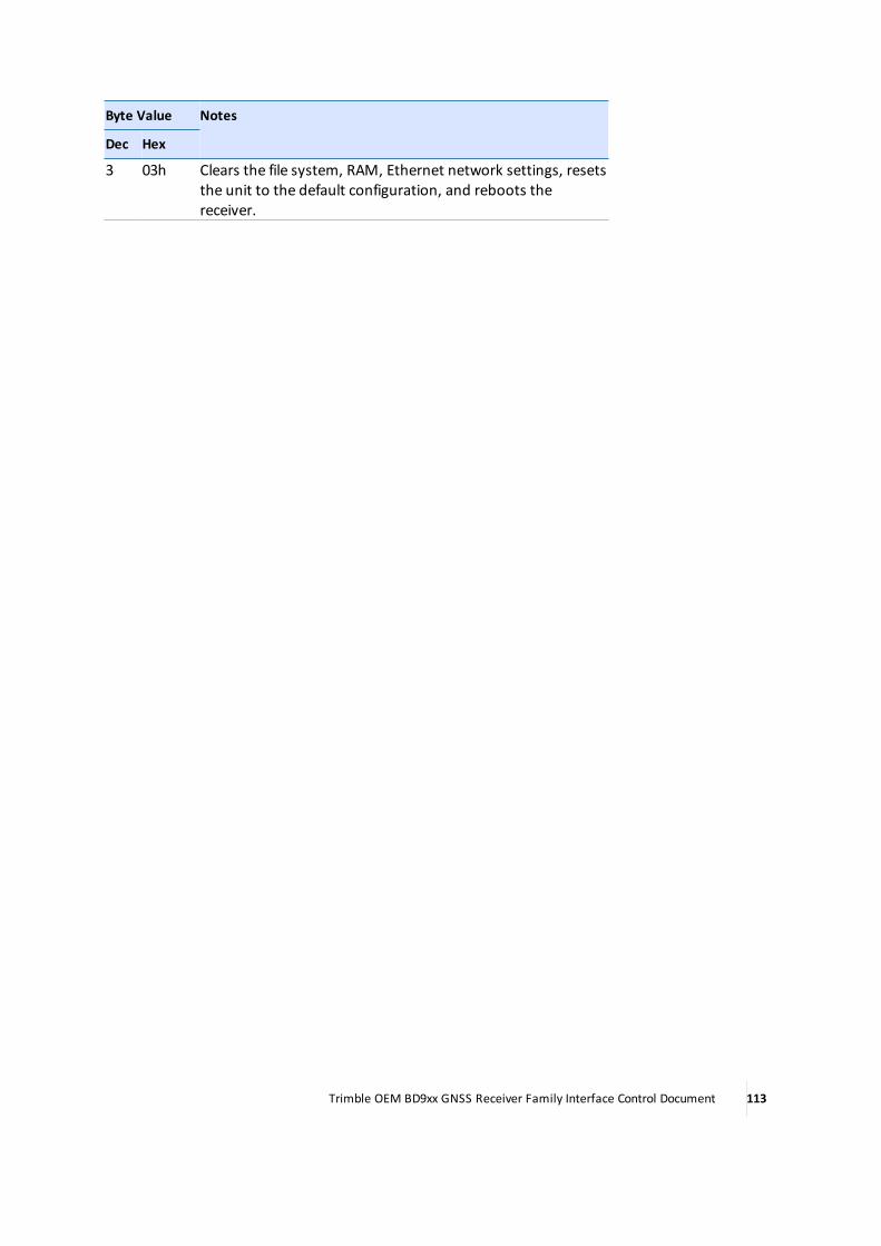
Byte Value Notes
Dec Hex
3 03h Clears the file system, RAM, Ethernet network settings, resetsthe unit to the default configuration, and reboots thereceiver.
Trimble OEM BD9xx GNSS Receiver Family Interface Control Document 113


