+ All Categories
Home > Documents > Triplex Ceramic Models Repair and Service Manual Operating ... · 2 NOTE: Contact Giant Industries...

Triplex Ceramic Models Repair and Service Manual Operating ... · 2 NOTE: Contact Giant Industries...

Date post: 18-Oct-2018
Category:
Upload: hoangtuong
View: 215 times
Download: 0 times
Share this document with a friend
12
Contents: Installation Instructions: page 2 Pump Specifications: page 3 Exploded View: page 4 Parts List/Kits: page 5 Repair Instructions: pages 6-8 Trouble Shooting: page 9 Recommended Spare Parts List: page 10 Torque Specifications: page 10 Pump Mounting Selection Guide: page 10 Dimensions: page 11 Warranty Information: back page Triplex Ceramic Plunger Pump Operating Instructions/ Repair and Service Manual Models LP122A-3100 & LP250-3100 Updated 6/12
Transcript

Contents:Installation Instructions: page 2Pump Specifications: page 3Exploded View: page 4Parts List/Kits: page 5Repair Instructions: pages 6-8Trouble Shooting: page 9Recommended Spare Parts List: page 10Torque Specifications: page 10Pump Mounting Selection Guide: page 10Dimensions: page 11Warranty Information: back page

Triplex CeramicPlunger Pump

Operating Instructions/ Repair and Service ManualModels

LP122A-3100 & LP250-3100

Updated 6/12

2

NOTE: Contact Giant Industries for Service School Information. Phone: (419)-531-4600

Installation InstructionsInstallation of the Giant Industries, Inc., pump is not a complicated procedure, but there are some basic steps common to all pumps. The following information is to be considered as a general outline for installation. If you have unique requirements, please contact Giant Industries, Inc. or your local distributor for as-sistance.

1. The pump should be installed flat on a base to a maximum of a 15 degree angle of inclination to ensure optimum lubrication.

2. The inlet to the pump should be sized for the flow rate of the pump with no unnecessary restric-tions that can cause cavitation. Teflon tape should be used to seal all joints. If pumps are to be oper-ated at temperatures in excess of 160o F for the LP122A-3100 pump or 86o F for the LP250-3100 pump, it is important to insure a positive head to the pump to prevent cavitation.

3. The discharge plumbing from the pump should be properly sized to the flow rate to prevent line pressure loss to the work area. It is essential to provide a safety bypass valve between the pump and the work area to protect the pump from pres-sure spikes in the event of a blockage or the use of a shut-off gun.

Finally, remember that high pressure operation in a pump system has many advantages. But, if it is used carelessly and without regard to its potential hazard, it can cause serious injury.

IMPORTANT OPERATING CONDITIONS

Failure to comply with any of these conditions invalidates the warranty.

1. Prior to initial operation, add oil to the crankcase so that oil level is between the two lines on the oil dipstick. DO NOT OVERFILL.

Use SAE 80-90W Industrial Gear Lube Oil (p/n 01154)

Crankcase oil should be changed after the first 50 hours of operation, then at regular intervals of 500 hours or less depending on operating conditions.

4. Use of a dampener is necessary to minimize pul-sation at drive elements, plumbing, connections, and other system areas. The use of a dampener with Giant Industries, Inc. pumps is optional, although recommended by Giant Industries, Inc. to further reduce system pulsation. Dampeners can also reduce the severity of pressure spikes that occur in systems using a shut-off gun. A dampener must be positioned downstream from the unloader.

5. Crankshaft rotation on Giant Industries, Inc. pumps should be made in the direction designated by the arrows on the pump crankcase. Reverse rotation may be safely achieved by following a few guidelines available upon request from Giant Indus-tries, Inc. Required horsepower for system opera-tion can be obtained from the charts on pages 3.

6. Before beginning operation of your pumping system, remember: Check that the crankcase and seal areas have been properly lubricated per recom-mended schedules. Do not run the pump dry for extended periods of time. Cavitation will result in severe damage. Always remember to check that all plumbing valves are open and that pumped media can flow freely to the inlet of the pump.

2. Pump operation must not exceed rated pressure, volume, or RPM. A pressure relief device must be installed in the discharge of the system.

3. Acids, alkalines, or abrasive fluids cannot be pumped unless approval in writing is obtained before operation from Giant Industries, Inc.

4. Run the pump dry approximately 10 seconds to drain the water before exposure to freezingtemperatures.

3

Pump speeds of 640 RPM and above require a minimum inlet pressure of 12 psig.

PULLEY INFORMATIONPulley selection and pump speed are based on a 1725 RPM motor and “B” section belts. When selecting desired GPM, allow for a ±5% tolerance on pumps output due to variations in pulleys, belts and motors among manufacturers.1. Select GPM required, then select appropriate motor and

pump pulley from the same line.2. The desired pressure is achieved by selecting the correct

nozzle size that corresponds with the pump GPM.

HORSEPOWER INFORMATIONWe recommend that a 1.1 service factor be specified when s electing an electric motor as the power source. To compute specific pump horsepower requirements, use the following formula:

HP = (GPM X PSI) / 1440

RPM GPM 600 PSI 800 PSI 1000 PSI 1300 PSI500 22.3 9.3 12.4 15.5 20.1555 24.7 10.3 13.7 17.2 22.3640 28.5 11.9 15.8 19.8 25.7695 30.9 12.9 17.2 21.5 27.9750 33.4 13.9 18.6 23.2 30.2800 35.6 14.8 19.8 24.7 32.1

LP122A-3100 PULLEY SELECTION AND HORSEPOWER REQUIREMENTS

LP122A-3100 Specifications U.S. MetricVolume........................................................................................... 35.6 GPM ............................................ 134.7 L/minDischarge Pressure ....................................................................... 1300 PSI .......................................................90 BarInlet Pressure ................................................................................ 90 PSI ..........................................................6.2 BarSpeed .....................................................................................................................................................Up to 800 RPMPlunger Diameter........................................................................... 1.65” ............................................................. 42 mm Stroke ............................................................................................ 1.65” ............................................................. 42 mmCrankcase Oil Capacity ................................................................. 116 fl.oz. ...................................................3.43 litersTemperature of Pumped Fluids ..................................................... 160oF............................................................... 71oCInlet Port ..................................................................................................................................................2 x 1-1/2” BSPDischarge Port ...............................................................................................................................................2 x 1” BSPCrankshaft Mounting .....................................................................................................................................Either SideShaft Rotation ..............................................................................................................Top of Pulley Towards Fluid EndWeight ........................................................................................... 116 lbs. ........................................................ 52.6 kgCrankshaft Diameter...................................................................... 1.38 .............................................................. 35 mmValve Casing ............................................................................................................................ Nickle Aluminum BronzeVolumetric Efficiency @ 800 RPM ........................................................................................................................... 0.96Mechanical Efficiency @ 800 RPM ......................................................................................................................... 0.85

LP250-3100 Specifications U.S. MetricVolume........................................................................................... 25.7 GPM .............................................. 97.3 L/minDischarge Pressure ....................................................................... 2030 PSI .....................................................140 BarInlet Pressure ................................................................................ 90 PSI ..........................................................6.2 BarSpeed ...................................................................................................................................................Up to 1000 RPMPlunger Diameter........................................................................... 1.30” ............................................................. 32 mm Stroke ............................................................................................ 1.65” ............................................................. 42 mmCrankcase Oil Capacity ................................................................. 116 fl.oz. ...................................................3.43 litersTemperature of Pumped Fluids ..................................................... 86oF................................................................. 30oCInlet Port ..................................................................................................................................................2 x 1-1/2” BSPDischarge Port ...............................................................................................................................................1 x 1” BSPCrankshaft Mounting .....................................................................................................................................Either SideShaft Rotation ..............................................................................................................Top of Pulley Towards Fluid EndWeight ........................................................................................... 126 lbs. .......................................................... 57 kgCrankshaft Diameter............................................................................................................................................ 35 mmValve Casing ............................................................................................................................ Nickle Aluminum BronzeNPSHR .......................................................................................... 25.6 ft. of Head ........................7.8 meters of Water

RPM GPM 600 PSI 800 PSI 1000 PSI 1600 PSI 2030 PSI500 12.9 5.4 7.1 8.9 14.3 18.1600 15.4 6.4 8.6 10.7 17.1 21.7700 18 7.5 10.0 12.5 20.0 25.4800 20.6 8.6 11.4 14.3 22.8 29.0900 23.1 9.6 12.9 16.1 25.7 32.61000 25.7 10.7 14.3 17.8 28.6 36.2

LP250-3100 PULLEY SELECTION AND HORSEPOWER REQUIREMENTS

4

LP122A-3100 & LP250-3100 Exploded View

5

Item Part # Description Qty.1 07759 Crankcase 1 2 13000 Oil Filler Plug 13 05940 Cover Plate 13A 07223-0100 Spring Washer 23B 05051-0100 Hexagon Screw 24 06085 Crankcase Cover 15 07104 O-Ring 1 6 07186 Oil Sight Glass with Gasket 18 06086 Oil Dipstick 19 01009 O-Ring 110 01010-0100 Screw 411 01011-0400 Spring Washer 512 07109-0400 Oil Drain Plug 113 07182 Gasket 114 07111 Bearing Cover 215 07112 Crankshaft Seal 216 07113 O-Ring 217 07114-0100 HexScrew 820 07116 Taper Roller Bearing 220A 07117 Fitting Disc, 0.1mm 1-320B 13001 Fitting Disc, 0.15mm 1-321 05376 Shaft Protector 122 13242 Crankshaft 123 13243 Key 124 13340 Connecting Rod Assy. 324A 13277 Hex Screw 624B 13278 Spring Washer 625 13341 Crosshead Plunger Base Assembly 328 13232 Crosshead Pin 329A 07735 Centering Sleeve 329B 07736 Plunger Pipe (LP122A-3100) 329B 13022 Plunger Pipe (LP250-3100) 329C 07737-0100 Plunger Bolt 329D 07161A-0100 Gasket for Bolt 329E 06618 Spacer Pipe 330 07779 Flinger 3

Item Part # Description Qty.31 07133 Radial Shaft Seal 335 13342-0100 Seal Sleeve (LP122A-3100) 335 04138 Seal Sleeve (LP250-3100) 335A 06619 O-Ring 335B 13141-0001 O-Ring (LP250-3100) 336 13415 Grooved Ring (LP122A-3100) 336 13025 Grooved Ring (LP250-3100) 336A 13416A-0100 Pressure Ring (LP122A-3100) 336A 06700 Pressure Ring (LP250-3100) 336B 06174 Drip Shield 337 04124 Support Disc (LP250-3100) 339 07744-0100 Pressure Ring (LP122A-3100) 339 13026-0100 Pressure Ring (LP250-3100) 340 07745 Sleeve (LP122A-3100) 640 13027 Sleeve (LP250-3100) 641 07746-0100 Support Ring (LP122A-3100) 341 06702 Support Ring (LP250-3100) 342 06589 Plug, 1/8” BSP 342A 07204-0100 Steel Ring 343 13343-3000 Valve Casing 144 07748-0300 Valve Seat 644A 07150-0001 O-Ring 645 07749-0100 Valve Plate 646 07750 Valve Spring 646A 07751-0100 Valve Assy. Complete 647 07752 Spring Tension Cap 648 06089 Plug 648A 06577 O-Ring 649 07157 Stud Bolt 849A 07158 Nut 849B 07159 Washer 850 07423-0100 Plug 150A 07755-0100 Gasket 152 13020 Disk for Crankshaft 153 06607 Hexagon Screw 154 13044-0100 Plug 1” BSP 155 13322-0100 Plug, 1” BSP 1

LP122A-3100 & LP250-3100 Spare Parts List

LP122A-3100 & LP250-3100 Repair KitsLP122A-3100 Plunger Packing Kit # 09575Item Part# Description Qty.35A 06619 O-Ring 336 13415 Grooved Ring 336B 06174 Drip Shield 340 07745 Sleeve 6

LP250-3100 Plunger Packing Kit# 09739Item Part# Description Qty.35A 06619 O-Ring 335B 13141-0001 O-Ring 336 13415 Grooved Ring 340 07745 Sleeve 6

Valve Assembly Kit #09576Item Part # Description Qty.44 07748-0300 Valve Seat 644A 07150-0001 O-Ring 645 07749-0300 Valve Plate 646 07750 Valve Spring 647 07752 Spring Tension Cap 648A 06577 O-Ring 6

Oil Seal Kit # 09577Item Part# Description Qty.31 07133 Radial Shaft Seal 3

6

LP122A-3100 & LP250-3100 Repair Instructions

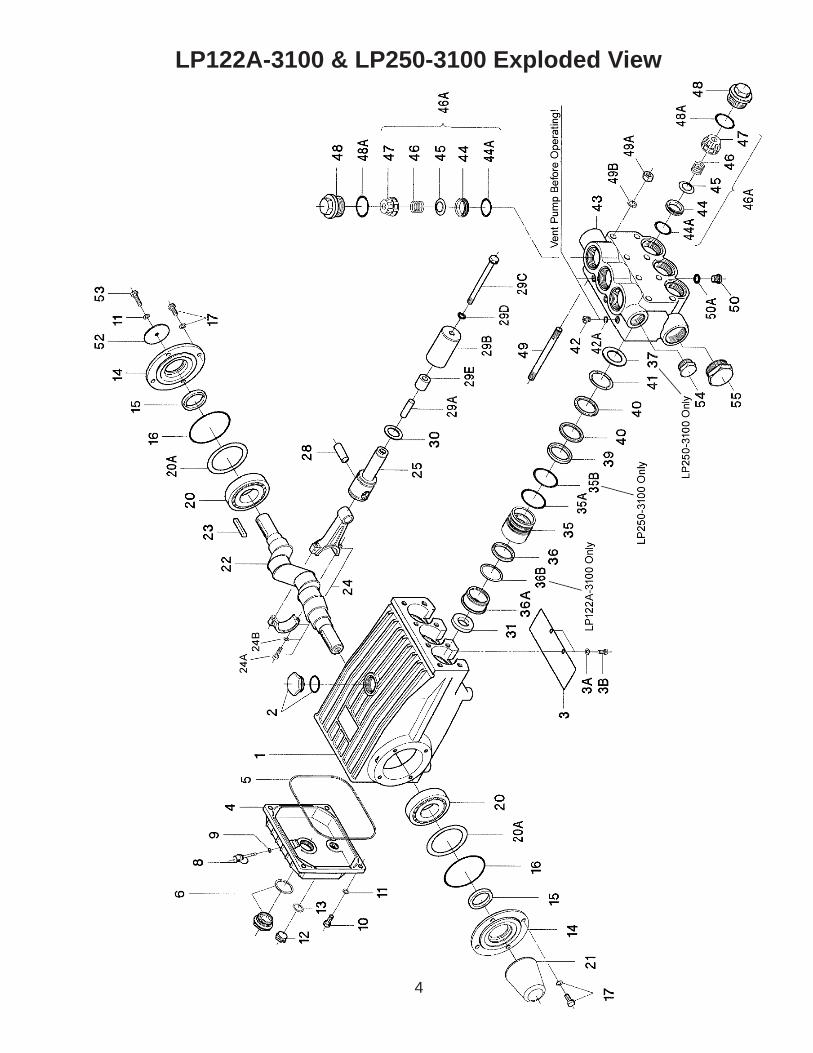
1. With a 30mm wrench, re-move the six (6) plugs (48) from the valve casing (43). Inspect the o-rings (48A) and replace if necessary.

Remove the complete valve assembly (46A) by threading a 12mm bolt into the spring retainer and pulling straight out.

2. To disassemble the valve, screw the bolt into the retainer until the valve plate (45) presses the valve seat (44) out of the spring retainer. Examine all parts and replace if necessary. If the seat doesn’t come out, use a valve puller to remove.

3. Remove the eight (8) hex nuts (49A) with a 19mm wrench. Tap the back of the manifold (43) with a rubber mallet to dislodge and slide off the studs.

4. Remove the seal sleeve (35) from the manifold and/or crank-case. Remove the pressure rings (39 & 36A), drip shield for LP122A-3100 only (36B), v-sleeves (40 & 36), support ring (41) and o-rings (35A) from the manifold and seal sleeve, respectively. LP250-3100 pumps also have a support disc (37) and an O-ring (35B) for the seal sleeve. Examine seals carefully and replace if worn. Clean all parts.

44A 44 45 48 47

LP122A-3100 Only LP250-3100 Only LP250-3100 Only

7

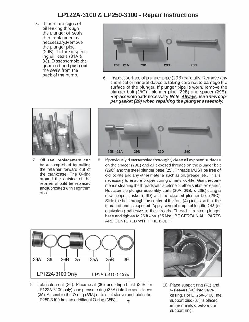
8. If previously disassembled thoroughly clean all exposed surfaces on the spacer (29E) and all exposed threads on the plunger bolt (29C) and the steel plunger base (25). Threads MUST be free of old loc-tite and any other material such as oil, grease, etc. This is necessary to ensure proper curing of new loc-tite. Giant recom-mends cleaning the threads with acetone or other suitable cleaner. Reassemble plunger assembly parts (29A, 29B, & 29E) using a new copper gasket (29D) and the cleaned plunger bolt (29C). Slide the bolt through the center of the four (4) pieces so that the threaded end is exposed. Apply several drops of loc-tite 243 (or equivalent) adhesive to the threads. Thread into steel plunger base and tighten to 26 ft.-lbs. (35 Nm). BE CERTAIN ALL PARTS ARE CENTERED WITH THE BOLT!

7. Oil seal replacement can be accomplished by pulling the retainer forward out of the crankcase. The O-ring around the outside of the retainer should be replaced and lubricated with a light film of oil.

29E 29A 29B 29D 29C

LP122A-3100 & LP250-3100 - Repair Instructions

9. Lubricate seal (36). Place seal (36) and drip shield (36B for LP122A-3100 only), and pressure ring (36A) into the seal sleeve (35). Assemble the O-ring (35A) onto seal sleeve and lubricate.

LP250-3100 has an additional O-ring (35B).

10. Place support ring (41) and v-sleeves (40) into valve casing. For LP250-3100, the support disc (37) is placed in the manifold before the support ring.

6. Inspect surface of plunger pipe (29B) carefully. Remove any chemical or mineral deposits taking care not to damage the surface of the plunger. If plunger pipe is worn, remove the plunger bolt (29C) , plunger pipe (29B) and spacer (29E). Replace worn parts necessary. Note: Always use a new cop-per gasket (29) when repairing the plunger assembly.

5. If there are signs of oil leaking through the plunger oil seals, then replacment is neccessary.Remove the plunger pipe (29B) before inspect- ing oil seals (31A & 33). Dissassemble the gear end and push out the seals from the back of the pump.

29E 29A 29B 29D 29C

LP122A-3100 Only LP250-3100 Only

8

11. Press seal sleeve assembly into the manifold and seat firmly. Put the support ring (41) on plunger with v-side facing the manifold.

12. Place entire manifold/seal sleeve assembly over the studs and push firmly until seated against the crank-case.

15. Replace plug with O-ring (48, & 48A) and tighten to 160 ft.-lbs. (217 Nm).

14. Next, place valve assemblies (46A) into manifold after first lubricating the O-ring (44A). Seat firmly into manifold.

13. Tighten hex nuts (49A) in a cross-wise pattern (shown above) to 60 ft.-lbs. (81 Nm).

16. Fill crankcase with approxi-mately 116 fluid ounces of Giant oil or equivalent SAE 90 industrial gear oil and check oil level of the crankcase with the dipstick. Proper level is center of two lines. Reinstall your Giant LP pump into your system.

Contact Giant Industries or your local distributor for maintenance of the gear end of your pump. Phone: 419/531-4600

Contact Giant Industries for service school information. Phone: (419) 531-4600

6 4 2 7

8 1 3 5

LP122A-3100 & LP250-3100 - Repair Instructions

9

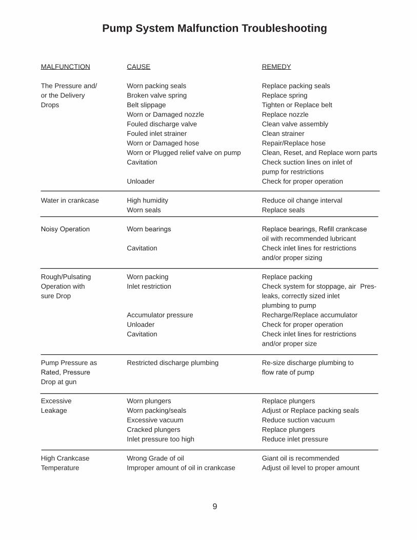
Pump System Malfunction Troubleshooting

MALFUNCTION CAUSE REMEDY

The Pressure and/ Worn packing seals Replace packing sealsor the Delivery Broken valve spring Replace springDrops Belt slippage Tighten or Replace belt Worn or Damaged nozzle Replace nozzle Fouled discharge valve Clean valve assembly Fouled inlet strainer Clean strainer Worn or Damaged hose Repair/Replace hose Worn or Plugged relief valve on pump Clean, Reset, and Replace worn parts Cavitation Check suction lines on inlet of pump for restrictions Unloader Check for proper operation

Water in crankcase High humidity Reduce oil change interval Worn seals Replace seals

Noisy Operation Worn bearings Replace bearings, Refill crankcase oil with recommended lubricant Cavitation Check inlet lines for restrictions and/or proper sizing

Rough/Pulsating Worn packing Replace packingOperation with Inlet restriction Check system for stoppage, air Pres-sure Drop leaks, correctly sized inlet plumbing to pump Accumulator pressure Recharge/Replace accumulator Unloader Check for proper operation Cavitation Check inlet lines for restrictions and/or proper size

Pump Pressure as Restricted discharge plumbing Re-size discharge plumbing to Rated, Pressure flow rate of pump Drop at gun Excessive Worn plungers Replace plungersLeakage Worn packing/seals Adjust or Replace packing seals Excessive vacuum Reduce suction vacuum Cracked plungers Replace plungers Inlet pressure too high Reduce inlet pressure

High Crankcase Wrong Grade of oil Giant oil is recommended Temperature Improper amount of oil in crankcase Adjust oil level to proper amount

10

Position Item# Description Torque Amount 10 01010-0100 Screw, Cover 125 in.-lbs. (14 Nm) 17 07114-0100 Hex Screw, Bearing Cover 125 in.-lbs. (14 Nm) 24A 13277 Hex Screw, Connecting Rod 250 in.-lbs. (28 Nm) 29C 07737-0100 Plunger Bolt 26 ft.-lbs. (35 Nm) 48 06089 Plug, Valve 160 ft.-lbs. (217 Nm) 49A 06577 Nut, Stud Bolt 60 ft.-lbs. (81 Nm)

LP122A-3100 & LP250-3100 Torque Specifications

Pump Mounting Selection Guide

Bushings06496 - 35mm H Bushing

Pulley & Sheaves07165 - 12.75” Cast Iron - 4 gr. - AB Section

Rails07357 - Plated Steel Channel Rails (L=11.75”xW1.88”xH=3.00”)

Preventative Maintenance Check List & Recommended Spare Parts List

Check Daily Weekly 50 hrs Every 500 hrs

Every 1500 hrs

Every 3000 hrs

Oil Level/Quality XOil Leaks XWater Leaks XBelts, Pulley XPlumbing X

Recommended Spare PartsOil Change p/n 01154 X X

Seal Spare Parts (1 kit/pump) (see page 5 for kit list) X

Oil Seal Kit (1 kit/pump) (see page 5 for kit list) X

Valve Spare Parts (1 kit/pump) (see page 5 for kit list)

X

11

LP122A-3100 & LP250-3100 Dimensions - Inches (mm)

GIANT INDUSTRIES, INC., 900 N. Westwood Avenue, P.O. Box 3187, Toledo, OH 43607PHONE: (419) 531-4600, FAX: (419) 531-6836, www.giantpumps.com

Copyright 2012 Giant Industries, Inc.06/12 LP122A_LP250-3100.indd

GIANT INDUSTRIES LIMITED WARRANTYGiant Industries, Inc. pumps and accessories are warranted by the manufacturer to be free from

defects in workmanship and material as follows:

1. For portable pressure washers and self-serve car wash applications, the discharge

manifolds will never fail, period. If they ever fail, we will replace them free of charge.

Our other pump parts, used in portable pressure washers and in car wash applications,

are warranted for five years from the date of shipment for all pumps used in NON-

SALINE, clean water applications.

2. One (1) year from the date of shipment for all other Giant industrial and consumer

pumps.

3. Six (6) months from the date of shipment for all rebuilt pumps.

4. Ninety (90) days from the date of shipment for all Giant accessories.

This warranty is limited to repair or replacement of pumps and accessories of which

the manufacturer’s evaluation shows were defective at the time of shipment by the manufacturer.

The following items are NOT covered or will void the warranty:

1. Defects caused by negligence or fault of the buyer or third party.

2. Normal wear and tear to standard wear parts.

3. Use of repair parts other than those manufactured or authorized by Giant.

4. Improper use of the product as a component part.

5. Changes or modifications made by the customer or third party.

6. The operation of pumps and or accessories exceeding the specifications set forth

in the Operations Manuals provided by Giant Industries, Inc.

Liability under this warranty is on all non-wear parts and limited to the replacement or repair of those

products returned freight prepaid to Giant Industries which are deemed to be defective due to work-

manship or failure of material. A Returned Goods Authorization (R.G.A.) number and completed

warranty evaluation form is required prior to the return to Giant Industries of all products under war-

ranty consideration. Call (419)-531-4600 or fax (419)-531-6836 to obtain an R.G.A. number.

Repair or replacement of defective products as provided is the sole and exclusive remedy provided

hereunder and the MANUFACTURER SHALL NOT BE LIABLE FOR FURTHER LOSS, DAMAGES,

OR EXPENSES, INCLUDING INCIDENTAL AND CONSEQUENTIAL DAMAGES DIRECTLY OR

INDIRECTLY ARISING FROM THE SALE OR USE OF THIS PRODUCT.

THE LIMITED WARRANTY SET FORTH HEREIN IS IN LIEU OF ALL OTHER WARRANTIES OR

REPRESENTATION, EXPRESS OR IMPLIED, INCLUDING WITHOUT LIMITATION ANY WAR-

RANTIES OR MERCHANTABILITY OR FITNESS FOR A PARTICULAR PURPOSE AND ALL SUCH

WARRANTIES ARE HEREBY DISCLAIMED AND EXCLUDED BY THE MANUFACTURER.


Recommended