15
An EXCLUSIVE kit brought to you by - www.HighScoreSaves.com TRON | SATANS HOLLOW MULTIGAME FREE PLAY AND HIGH SCORE SAVE KIT INSTALLATION GUIDE

An EXCLUSIVE kit brought to you by - www.HighScoreSaves.com
TRON | SATANS HOLLOW MULTIGAME FREE PLAY AND HIGH SCORE SAVE KIT INSTALLATION GUIDE

Steps for a successful install of your online or offline high score save kit – Ensure your gameboard is working 100% before installing kit Ensure power to game is off before removing your gameboard from
cabinet Label any connectors that you will be disconnecting. This will make
reinstalling easier once kit is on gameboard Note which way your edge connector is on. We suggest taking pictures
to help you remember! Work in a well lit area on your workbench OK, let me walk you through the install of the newest kit from HSS – The Multi Tron/Satan’s Hollow Free Play and High Score Save Kit! There are a few things that you need to read, so, please do so PRIOR to installation. 1. You wll be “folding” the pcb in a different order than the original 3 board stack layout. (To make the kit “fit” on the pcb “better”) 2. You will not have to remove your ribbon cables to do so! (Good news!) 3. You will have to remove the roms on the sound board and super CPU board. They are now on the kit, so, not needed on your pcb Just read through and take a look at the pictures 4. With the flat cable from the kit, it will end up underneath your pcb. This will effect how your pcb will sit back in the 3 grooves when you reinstall your pcb stack after kit installation. The front end will sit fine, please avoid pressure from top mounting bracket. 5. The headers used on the kit will have about 1mm of space from the socket and the black plastic part of the headers on the kit. In otherwords, you will see about 1mm of gold pins when the daughter cards are installed. That’s ok, they are still making great contact in the sockets.
….enjoy the ride PROGRAMS!

PART 1 – Identifying the boards in your PCB stack

Pic of the boards “spread out” (Ribbon cables stay attached)
PART 2 – Installing the Multi Tron Kit OK, you will need to open up your pcb stack. You may want to get a set of needle nosed pliers to compress the white tabs on the standoffs. These are on all 4 corners of your pcb stack. Leave the standoffs connected to the Super CPU pcb as we will be folding them back in a different way. It is NOT necessary to remove the ribbon cables on your pcb stack. Just leave them on. They are old and brittle….sort of like Mark Sp****. So be gentle.
Your pcb stack should look like the pic above identifying each individual pcb. So, let’s get to work!

A. Let’s start with the Graphics PCB – 1. Remove the eproms from A to E.
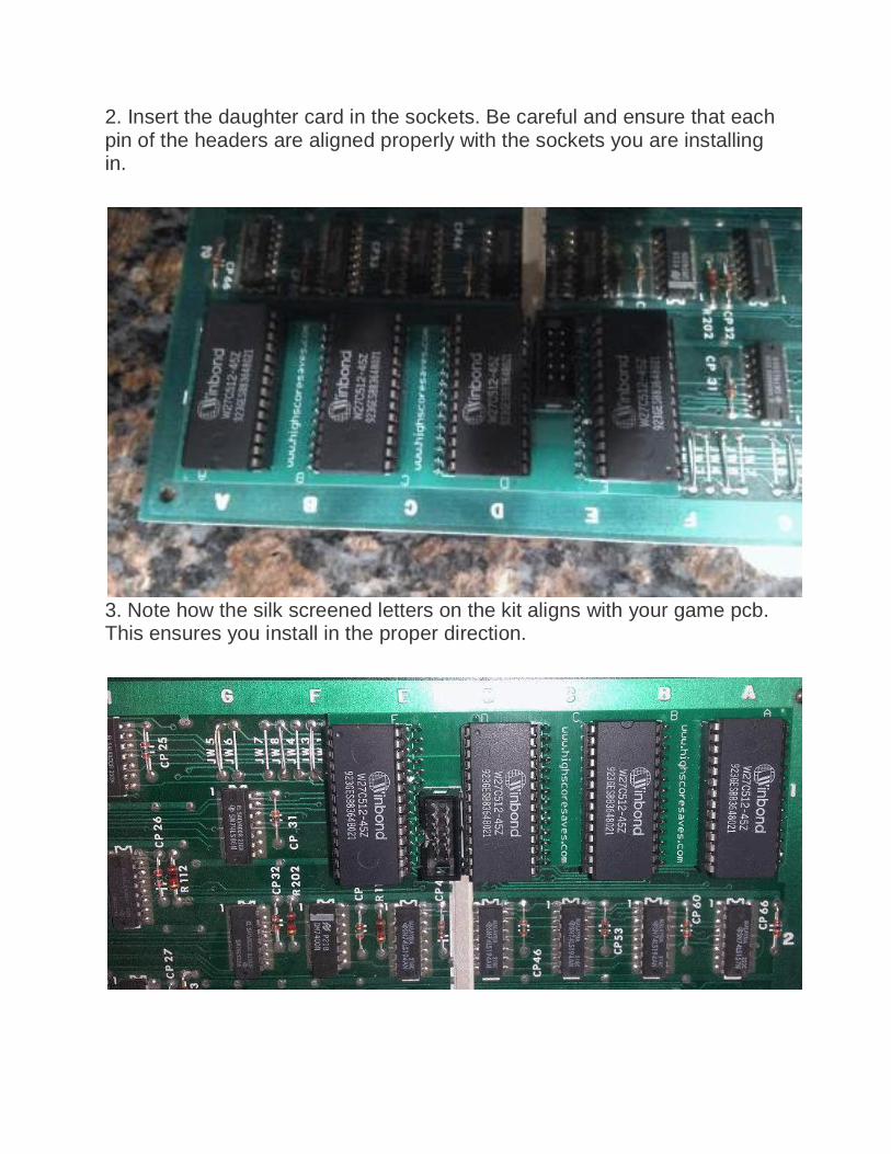
2. Insert the daughter card in the sockets. Be careful and ensure that each pin of the headers are aligned properly with the sockets you are installing in.
3. Note how the silk screened letters on the kit aligns with your game pcb. This ensures you install in the proper direction.
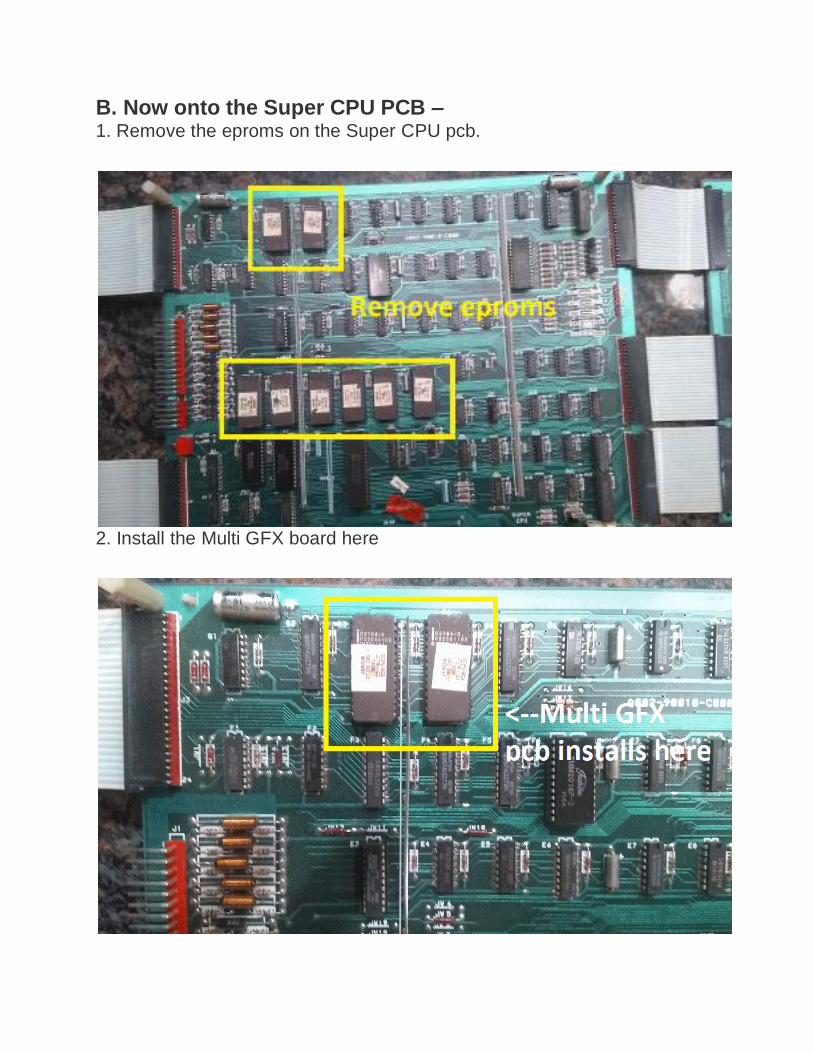
B. Now onto the Super CPU PCB – 1. Remove the eproms on the Super CPU pcb.
2. Install the Multi GFX board here
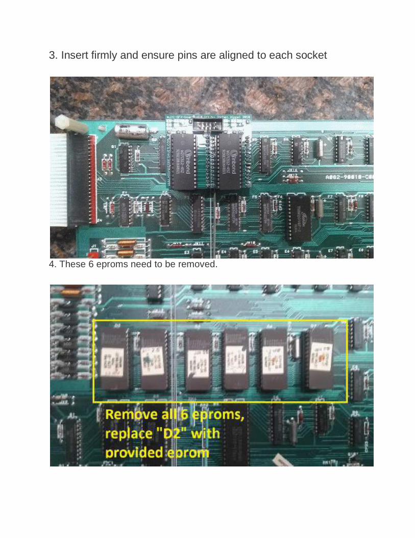
3. Insert firmly and ensure pins are aligned to each socket
4. These 6 eproms need to be removed.

5. Insert your new D2 eprom as shown
6. Now remove the z80 and install the main CPU pcb of the kit

7. Place the z80 you removed and put on the kit.
8. Now, connect the provided flat cable from the main CPU pcb to the GFX pcb. Note that there is only one way to connect due to length and the way the notches are crimped on the flat cable.
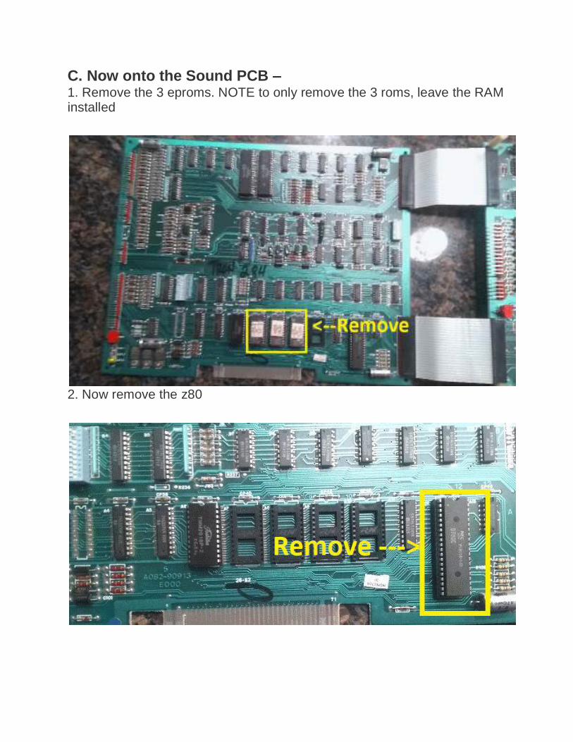
C. Now onto the Sound PCB – 1. Remove the 3 eproms. NOTE to only remove the 3 roms, leave the RAM installed
2. Now remove the z80

3. Use that z80 and install on the Sound pcb of the kit. You’ll end up looking like this
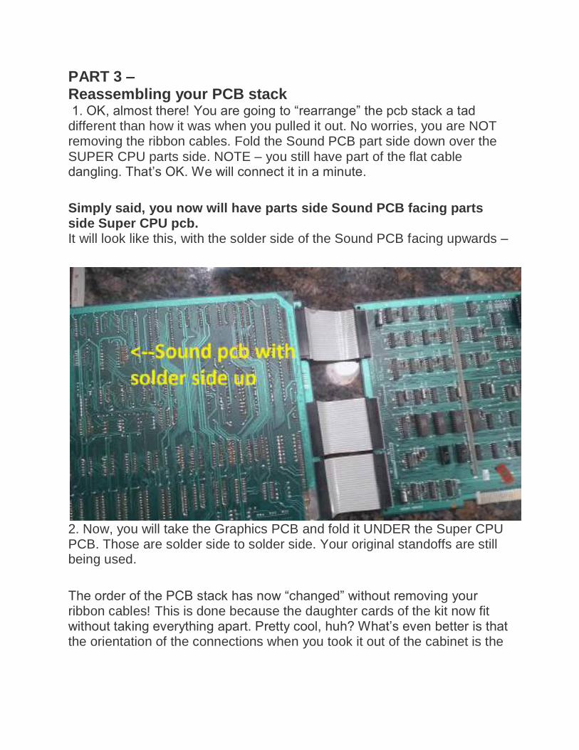
PART 3 – Reassembling your PCB stack 1. OK, almost there! You are going to “rearrange” the pcb stack a tad different than how it was when you pulled it out. No worries, you are NOT removing the ribbon cables. Fold the Sound PCB part side down over the SUPER CPU parts side. NOTE – you still have part of the flat cable dangling. That’s OK. We will connect it in a minute.
Simply said, you now will have parts side Sound PCB facing parts side Super CPU pcb. It will look like this, with the solder side of the Sound PCB facing upwards –
2. Now, you will take the Graphics PCB and fold it UNDER the Super CPU PCB. Those are solder side to solder side. Your original standoffs are still being used.
The order of the PCB stack has now “changed” without removing your ribbon cables! This is done because the daughter cards of the kit now fit without taking everything apart. Pretty cool, huh? What’s even better is that the orientation of the connections when you took it out of the cabinet is the

EXACT same when you install it back in. WOWZA! Good thing I aced the
Wonderlic test, huh?
3. With this stack now complete, you need to connect that dangling flat cable to the daughter card on the Graphics PCB.
After insertion, check the seating of the daughter boards again to ensure proper seating in the sockets.
Yes, kit inserted properly.
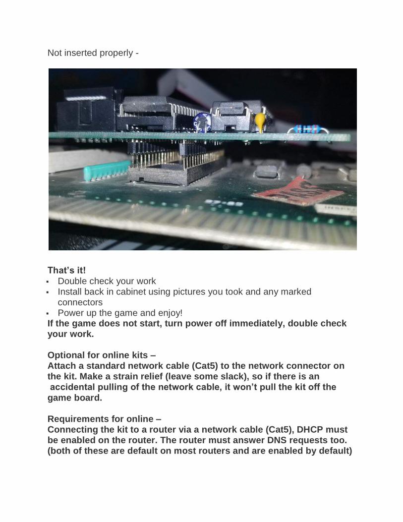
Not inserted properly -
That’s it! Double check your work Install back in cabinet using pictures you took and any marked
connectors Power up the game and enjoy! If the game does not start, turn power off immediately, double check your work. Optional for online kits – Attach a standard network cable (Cat5) to the network connector on the kit. Make a strain relief (leave some slack), so if there is an accidental pulling of the network cable, it won’t pull the kit off the game board. Requirements for online – Connecting the kit to a router via a network cable (Cat5), DHCP must be enabled on the router. The router must answer DNS requests too. (both of these are default on most routers and are enabled by default)


