Use Electrically Approved Plastic Enclosure Only *Do Not Mount TRX-MAINS in a Metal Enclosure. Suitable Enclosures: TB-AG-1010 (100 x 100mm) TB-AG-1115 (110 x 150mm)
Page 3
High Current Contactor Wiring *Only use Contactors with 230VAC Coil and Contacts to suit switched load.
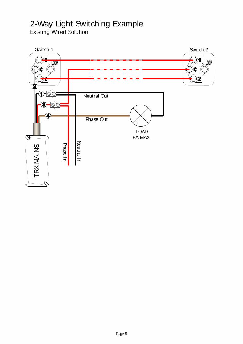
Phase In
Neutral In
TRX
MAI
NS
Phase Out
230VAC 230VAC
Page 4
Mounted inside plastic enclose TB-AG-1115 (110 x 150mm)
Warning: The TRX Mains relay is not suitable for mounting in accessible locations. It must be installed within an enclosure providing suitable insulation, as shown above.
Optional Override
Input
Page 5
Phase Out
Neutral Out
Phase In
Neutral In
Switch 1
TRX
MAI
NS
LOAD 8A MAX.
Switch 2
2-Way Light Switching Example Existing Wired Solution
TRX MAINS Programming Step 1 Option 1 Pairing to Transceiver using Magnet
1– Safely apply power to the TRX MAINS
2– Present & hold the Magnet next to the TRX MAINS (see diagram a). The TRX MAINS will start beeping as it searches for a device to pair with.
3- Now put the TRX TRANSCEIVER (connected to the ELITE S) into pairing mode, by pressing and hold-ing the red button for 2 seconds (see diagram b). The blue pairing LED should start flashing.
4- The Beeping from TRX MAINS should then stop, indicating pairing is complete. The blue LED on the TRX TRANSCEIVER will stop flashing after 60 seconds, or press the red button to make it stop.
Option 2 Pairing to Transceiver using IR Remote-10
1– Safely apply power to the TRX MAINS
2- Point the IR remote at the bottom of the TRX MAINS (see diagram c) and press P then E. The TRX MAINS will start beeping as it searches for a device to pair with.
3- Now put the TRX TRANSCEIVER (connected to the ELITE S) into pairing mode, by pressing and hold-ing the red button for 2 seconds (see diagram b). The blue pairing LED should start flashing.
4- The Beeping from TRX MAINS should then stop, indicating pairing is complete. The blue LED on the TRX TRANSCEIVER will stop flashing after 60 seconds, or press the red button to make it stop.
Page 6
MAGNET
-MAGNET ALIGNMENT-
diagram a Pairing Button
diagram b
diagram c QR CODE LINK TO IR-REMOTE
TRX MAINS Output Assignment
Advance Output Mapping (requires IR Remote-10)
The Default Assigned Output for the TRX MAINS is 8, to change this please follow the steps below: 1– Safely apply power to the TRX MAINS
2- Point the IR remote at the bottom of the TRX MAINS and press P followed by the Output you wish to Map it to (1-8) then E. The TRX MAINS should give a triple beep indicating this was successful.
Note. It is not recommended to Map to Output 1 or 2 as they are for Sirens by default.
3- Make a note of this number here and on the TRX MAINS.
Note. Multiple TRX MAINS can be paired to the same Output.
*With an Output Assigned in to the TRX MAINS it’s Trigger Input is not Directly linked to the Switched Output. If you wish the Trigger Input to activate the Switched Output you must program it into the Elite S Panel.
=
Programming Trigger Input to Switched Output Link with ESL Control Board
The ESL v908.12c has pre assigned slots for the TRX Mains devices. If you have an Elite-S or Elite-S-Lite Control board v908.12b or older please use programming on page 8 Follow the list below for the Addresses that relate to the TRX Mains Output number assigned: *Programming below is done from the Control Panel Keypad in Installer Mode.
Default = 8
Page 7
= 3 1– Learn State 1 (ON) to the first User slot P 18 E 90 E E (when beeping starts flick the switch connected to the TRX Mains On)
2– Learn State 2 (OFF) to the second User slot. if you have a momentary switch, skip this step P 18 E 91 E E (when beeping starts flick the switch connected to the TRX Mains Off)
3– Adjusting Output Reset Time, the default reset time is only 2 seconds. P 40 E 3 E 0 E (lights now will not automatically turn off)
= 5 1– Learn State 1 (ON) to the first User slot P 18 E 92 E E (when beeping starts flick the switch connected to the TRX Mains On)
2– Learn State 2 (OFF) to the second User slot. if you have a momentary switch, skip this step P 18 E 93 E E (when beeping starts flick the switch connected to the TRX Mains Off)
3– Adjusting Output Reset Time, the default reset time is only 2 seconds. P 40 E 5 E 0 E (lights now will not automatically turn off)
= 6 1– Learn State 1 (ON) to the first User slot P 18 E 94 E E (when beeping starts flick the switch connected to the TRX Mains On)
2– Learn State 2 (OFF) to the second User slot. if you have a momentary switch, skip this step P 18 E 95 E E (when beeping starts flick the switch connected to the TRX Mains Off)
3– Adjusting Output Reset Time, the default reset time is only 2 seconds. P 40 E 6 E 0 E (lights now will not automatically turn off)
= 7 1– Learn State 1 (ON) to the first User slot P 18 E 96 E E (when beeping starts flick the switch connected to the TRX Mains On)
2– Learn State 2 (OFF) to the second User slot. if you have a momentary switch, skip this step P 18 E 97 E E (when beeping starts flick the switch connected to the TRX Mains Off)
3– Adjusting Output Reset Time, the default reset time is only 2 seconds. P 40 E 7 E 0 E (lights now will not automatically turn off)
= 8 1– Learn State 1 (ON) to the first User slot P 18 E 98 E E (when beeping starts flick the switch connected to the TRX Mains On)
2– Learn State 2 (OFF) to the second User slot. if you have a momentary switch, skip this step P 18 E 99 E E (when beeping starts flick the switch connected to the TRX Mains Off)
3– Adjusting Output Reset Time, the default reset time is only 2 seconds. P 40 E 8 E 0 E (lights now will not automatically turn off)
=
Page 8
=
=
=
Ub=
Ub=
=
=
Ua=
Ua=
=
Ub=
=
Ua=
Ub=
Ua=
Ub=
Ua=
Assigning Input Control with Elite-S & Elite-S-Lite PCB
Choose 2 Spare User Slots from 21 to 100 and put them in where you see these boxes Don’t Do this programming if you have an ESL-PCB v908.12c (use page 7 instead)
*Programming below is done from the Control Panel Keypad in Installer Mode. 1– Learn State 1 to the first User slot P 18 E E (when beeping starts flick the switch connected to the TRX Mains On)
2– Learn State 2 to the second User slot. if you have a momentary switch, skip this step and 8 to 11 P 18 E E (when beeping starts flick the switch connected to the TRX Mains Off)
3– Set the User Assignment State 1 (by default all user slots Arm and Disarm, this needs to be changed) P 4 E E turn Off all options E
4– Output Mapping for State 1 P 12 E E E
5– Output On Command for State 1 P 13 E E E
6– Output Off Command for State 1 P 14 E E E
7– Output Permission P 34 E E turn On option 6 E
8– Output Reset Time P 40 E E turn On option 6 E
9– Set the User Assignment P 4 E E turn Off all options E
10– Output Mapping for State 2 P 12 E E E
11– Output On Command for State 2 P 13 E E E
12– Output Off Command for State 2 P 14 E E E
Ua= Ub=
Range Test Once you have learnt the Trigger Input into the panel, a range test is recommended
*Programming below is done from the Control Panel Keypad in Installer Mode. P 200 E 14 E E now Activate the Trigger Input The User Slot it has been loaded into will flash up and a percentage. 100% = full signal strength.
Note. Repeat the process for each TRX MAINS device, If less than 30% consider relocating the TRX Transceiver to get better signal strength.
Group Mode Programming
If Group Mode has been selected, the TRX MAINS will turn On when Output 7 from the panel turns On and will turn Off when Output 8 from the panel turns On. This allow multiple TRX MAINS modules all set to Group Mode to turn off and on together from a panel request, such as: Arming/Disarming the alarm, Fire/Burglar alarm activation, Timer control. In Group Mode the Trigger Input is always directly linked to the Switched Output. A change in state of the Trigger Input will change the Switched Output state, regardless of what position the switch is in.
Selecting Group Mode
To set a TRX MAINS to Group Mode you must use the IR-Remote-10 1– Safely apply power to the TRX MAINS 2- Point the IR remote at the bottom of the TRX MAINS (see diagram c) and press P, 0 then E. The TRX MAINS will give a triple beep if accepted.
Programming Options *Programming below is done from the Control Panel Keypad in Installer Mode.
Lights Off when System is Armed
P 47 E 1 E (turn 8 On) E
Lights On when System is Disarmed
P 49 E 1 E (turn 7 On) E
Lights On when Fire Alarm Activates
P 130 E (zone No. of smoke detector 1-16) E (turn 7 On) E (must be done for each 24-hour Fire zone)
Lights On when Burglar Alarm Activates
P 128 E (zone No. of detector 1-16) E (turn 7 On) E (must be done for each zone/detector)
Lights On when Stay Burglar Alarm Activates
P 129 E (zone No. of detector 1-16) E (turn 7 On) E (must be done for each zone/detector)
Page 9
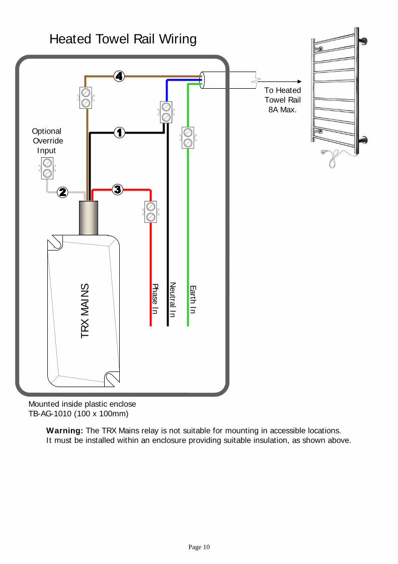
Heated Towel Rail Wiring
Phase In
Neutral In
TRX
MAI
NS
Optional Override
Input
Earth In
To Heated Towel Rail 8A Max.
Mounted inside plastic enclose TB-AG-1010 (100 x 100mm)
Warning: The TRX Mains relay is not suitable for mounting in accessible locations. It must be installed within an enclosure providing suitable insulation, as shown above.
Page 10
=
=
=
1– Set On Time 1. P 172 E 1 E (enter start time is 24hr format 0000-2359) E
2- Set Off Time 1. note Off time must be after On time. P 173 E 1 E (enter finish time is 24hr format 0000-2359) E
3- Set Timer 1 Days of Week. P 171 E 1 E (put in day active days 1-7, see table) E 4- Assign Timer 1 to an Output. P 44 E (enter output number ) E 1 E 5– Changing Reset Timer of Output. P 40 E E 0 E
Need another On and Off sequence? Follow the steps below. 6– Set On Time 2. P 172 E 2 E (enter start time is 24hr format 0000-2359) E
7- Set Off Time 2. note Off time must be after On time. P 173 E 2 E (enter finish time is 24hr format 0000-2359) E
8- Set Timer 2 Days of Week. P 171 E 2 E (put in day active days 1-7, see table) E 9- Assign Timer 2 to an Output. P 44 E (enter output number) E 2 E
Automatic On/Off timer (Recommended for Heated Towel Rail) There are 8 different On/Off timers that can be set in the Elite-S series control panel. Before starting the Programming steps below make sure the TRX Mains has been paired to the TRX Transceiver (see page 6) and an Output number has been assigned (see page 7). *Programming below is done from the Control Panel Keypad in Installer Mode.
Smart Features
Automatic Turn Lights Off when System Arms Each Output (TRX MAINS) can be Selected to turn Off when the Alarm System is Armed.
*Programming below is done from the Control Panel Keypad in Installer Mode. P 54 E 1 E E (each TRX Mains number can be turned on here)
Note. Don’t turn on 1 or 2 this will trigger the sirens
=
Adjusting Lights On Exit Timer Once you have turned On the option above, you can choose to extend the Off delay time up to 25 sec-onds. This will give you an illuminated exit from the property before turning the lights Off. Each Output (TRX MAINS) can be adjusted individually.
*Programming below is done from the Control Panel Keypad in Installer Mode. P 39 E E time in 10ths/second 1-255 E (250 = 25seconds)
Note. Repeat the process for each TRX MAINS you wish to have this feature
=
Fallback Feature If communication is lost to the TRX Transceiver, the TRX Mains will automatically Fallback and operating directly from it’s Trigger Input.