ETSI TS 102 800 V1.1.1 (2011-01) Technical Specification Electromagnetic compatibility and Radio spectrum Matters (ERM); Cognitive Programme Making and Special Events (C-PMSE); Protocols for spectrum access and sound quality control systems using cognitive interference mitigation techniques
Transcript
ETSI TS 102 800 V1.1.1 (2011-01)
Technical Specification
Electromagnetic compatibility and Radio spectrum Matters (ERM);
Cognitive Programme Making and Special Events (C-PMSE);Protocols for spectrum access and sound quality control
systems using cognitive interference mitigation techniques
ETSI
ETSI TS 102 800 V1.1.1 (2011-01)2
Reference DTS/ERM-TG17WG3-012
Keywords PMSE, radio, SRD
ETSI
650 Route des Lucioles F-06921 Sophia Antipolis Cedex - FRANCE
Tel.: +33 4 92 94 42 00 Fax: +33 4 93 65 47 16
Siret N° 348 623 562 00017 - NAF 742 C
Association à but non lucratif enregistrée à la Sous-Préfecture de Grasse (06) N° 7803/88
Important notice
Individual copies of the present document can be downloaded from: http://www.etsi.org
The present document may be made available in more than one electronic version or in print. In any case of existing or perceived difference in contents between such versions, the reference version is the Portable Document Format (PDF).
In case of dispute, the reference shall be the printing on ETSI printers of the PDF version kept on a specific network drive within ETSI Secretariat.
Users of the present document should be aware that the document may be subject to revision or change of status. Information on the current status of this and other ETSI documents is available at
http://portal.etsi.org/tb/status/status.asp
If you find errors in the present document, please send your comment to one of the following services: http://portal.etsi.org/chaircor/ETSI_support.asp
Copyright Notification
No part may be reproduced except as authorized by written permission. The copyright and the foregoing restriction extend to reproduction in all media.
DECTTM, PLUGTESTSTM, UMTSTM, TIPHONTM, the TIPHON logo and the ETSI logo are Trade Marks of ETSI registered for the benefit of its Members.
3GPPTM is a Trade Mark of ETSI registered for the benefit of its Members and of the 3GPP Organizational Partners. LTE™ is a Trade Mark of ETSI currently being registered
for the benefit of its Members and of the 3GPP Organizational Partners. GSM® and the GSM logo are Trade Marks registered and owned by the GSM Association.
Intellectual Property Rights ................................................................................................................................ 5
5 Technical Specification of the Cognitive Engine ................................................................................... 12
5.1 Functional architecture of the CEN .................................................................................................................. 12
5.1.1 Requirements on CEN Architecture ........................................................................................................... 13
5.6 rmi API ............................................................................................................................................................. 17
5.7 cmi API ............................................................................................................................................................ 18
5.8 sci API .............................................................................................................................................................. 18
5.9 sli API ............................................................................................................................................................... 18
6.1.2 Data storage Blocks .................................................................................................................................... 20
6.1.2.1 Radio Environmental Map (REM) ........................................................................................................ 20
6.1.2.2 Link Parameter Set (LPS) ..................................................................................................................... 21
6.1.2.2.1 Frequency Allocation Table (FAT) ................................................................................................. 21
6.1.2.2.2 The Power Allocation Table (PAT) ................................................................................................. 22
7.3.2 Definition of database language elements .................................................................................................. 25
7.4 Processing of database language ...................................................................................................................... 26
8.2 Data tansfer from RRM to PMO (rpi) .............................................................................................................. 28
8.3 Data transfer from CEN to PMO (cmi) ............................................................................................................ 29
9.1.3 SLE connected to SLM and DAT ............................................................................................................... 32
9.2 Service Level Monitor (SLM) .......................................................................................................................... 32
9.2.1 Data received by SLM from SLE and PMSE link ...................................................................................... 33
9.2.2 SLM data sent to CEN ................................................................................................................................ 33
10 Technical Specification of Scanning Receiver Subsystem (SCS) .......................................................... 33
10.2.1 Location of SCRs ........................................................................................................................................ 34
10.2.2 Features ....................................................................................................................................................... 35
10.2.2.1 Support for different measurement types .............................................................................................. 35
10.2.2.2 Queuing of Jobs .................................................................................................................................... 36
10.2.2.3 Antenna pattern control ......................................................................................................................... 36
10.2.2.4 Automatic detection of location ............................................................................................................ 36
10.2.2.5 Automatic detection of time .................................................................................................................. 36
10.4 Interface sci between Cognitive Engine (CEN) and Scanning Receiver controller (SCC) .............................. 37
10.5 Technical Specifications of the interface between Scanning Receiver Controller (SCC) and Scanning Receiver (SCR) ................................................................................................................................................ 37
10.5.1 Interface between Scanning Receiver Controller (SCC) and Scanning Receiver (SCR) ............................ 37
10.5.2 Scanning jobs .............................................................................................................................................. 38
10.5.3.1 Frequency domain measurement report ................................................................................................ 38
10.5.3.2 Time domain measurement report ......................................................................................................... 38
10.5.3.3 IQ samples measurement report ............................................................................................................ 38
10.5.4 Other commands ......................................................................................................................................... 39
11 RF Parameters & Service Levels ............................................................................................................ 39
Annex A (informative): Bibliography ................................................................................................... 43
History .............................................................................................................................................................. 44
ETSI
ETSI TS 102 800 V1.1.1 (2011-01)5
Intellectual Property Rights IPRs essential or potentially essential to the present document may have been declared to ETSI. The information pertaining to these essential IPRs, if any, is publicly available for ETSI members and non-members, and can be found in ETSI SR 000 314: "Intellectual Property Rights (IPRs); Essential, or potentially Essential, IPRs notified to ETSI in respect of ETSI standards", which is available from the ETSI Secretariat. Latest updates are available on the ETSI Web server (http://webapp.etsi.org/IPR/home.asp).
Pursuant to the ETSI IPR Policy, no investigation, including IPR searches, has been carried out by ETSI. No guarantee can be given as to the existence of other IPRs not referenced in ETSI SR 000 314 (or the updates on the ETSI Web server) which are, or may be, or may become, essential to the present document.
Foreword This Technical Specification (TS) has been produced by ETSI Technical Committee Electromagnetic compatibility and Radio spectrum Matters (ERM).
Introduction The present document focussed on audio link quality control; however the schemes depicted here are generic and can also be applied for video and effect control links.
This technical specification will serve as basis for designing a C-PMSE demonstrator. The experience during design and practical or virtual operation of the demonstrator will be summarized in the upcoming TR 102 801 [i.3].
PMSE systems are used to convey voice and music for live events such as conferences, concerts and theatrical performances, or for recorded productions of film and television programs. In these applications, the highest attainable level of sound quality and reliability is expected. Dropouts, noise and interference are not acceptable.
Protection
In order for PMSE devices to function properly, they must be protected from interference because they use very low radiated power levels in comparison to most other radio communications systems. Up to now this has not been a problem since PMSE equipment operated in locally unused TV channels that presented a very predictable RF environment. In the future, many different kinds of new devices, the characteristics of which are difficult to fully anticipate at this time, may be sharing this space. The question of how to protect PMSE equipment from interference caused by these new devices has been the subject of much discussion and debate. Some of these devices will be used for broadband data, and will occupy any spectrum which is available to them, i.e. from a few MHz to a multiple of 10 MHz. Other possible uses of the Digital Dividend may include emergency communications and other mobile services. Traditionally, incompatible radio communications systems were assigned to operate in separate frequency bands, but this scheme is becoming impractical in today's world of intensive spectrum use. A more dynamic solution is needed, but it must be robust.
To address this problem, the concept of the Cognitive PMSE (C-PMSE) system is proposed herein. The C-PMSE system is designed to respond dynamically to changes in the radio environment in order to maintain the quality of service required by the PMSE user.
Spectrum efficiency
The regulations governing the operation of PMSE (Program Making and Special Events) systems are currently in flux in Europe and elsewhere. As a result of the switchover from analogue to digital TV broadcasting, the amount of spectrum allocated for television transmission below 790 MHz is being reduced. The spectrum between 790 MHz and 862 MHz is considered a Digital Dividend and has been reallocated for use by Electronic Communication Networks [i.4]. These changes have resulted in a significant reduction in the amount of spectrum available for PSME operation.
The adoption of the C-PMSE system offers a high potential for increasing overall spectrum efficiency and improving coexistence between PMSE systems and local frequency management. This report describes various techniques that can be used in such a system.
ETSI
ETSI TS 102 800 V1.1.1 (2011-01)7
1 Scope The present document defines the architecture and functional blocks for a C-PMSE system together with the protocols and interfaces which link them. The findings are based on the technical recommendations in TR 102 799 [i.1].
2 References References are either specific (identified by date of publication and/or edition number or version number) or non-specific. For specific references, only the cited version applies. For non-specific references, the latest version of the reference document (including any amendments) applies.
Referenced documents which are not found to be publicly available in the expected location might be found at http://docbox.etsi.org/Reference.
NOTE: While any hyperlinks included in this clause were valid at the time of publication ETSI cannot guarantee their long term validity.
2.1 Normative references The following referenced documents are necessary for the application of the present document.
[1] ETSI EN 300 422-1 (V1.3.2): "Electromagnetic compatibility and Radio spectrum Matters (ERM); Wireless microphones in the 25 MHz to 3 GHz frequency range; Part 1: Technical characteristics and methods of measurement".
2.2 Informative references The following referenced documents are not necessary for the application of the present document but they assist the user with regard to a particular subject area.
[i.1] ETSI TR 102 799: "Electromagnetic compatibility and Radio spectrum Matters (ERM); Operation methods and principles for spectrum access systems for PMSE technologies and the guarantee of a high sound production quality on selected frequencies utilising cognitive interference mitigation techniques".
[i.2] ETSI TR 102 546 (V1.1.1): "Electromagnetic compatibility and Radio spectrum Matters (ERM); Technical characteristics for Professional Wireless Microphone Systems (PWMS); System Reference Document".
[i.3] ETSI TR 102 801: "Electromagnetic compatibility and Radio spectrum Matters (ERM); Test reports from technology demonstrator implementing TS 102 800 on protocols for spectrum access and sound quality control systems for PMSE applications using cognitive interference mitigation techniques".
[i.4] Commission Decision 2010/267/EU of 6 May 2010 on harmonised technical conditions of use in the 790-862 MHz frequency band for terrestrial systems capable of providing electronic communications services in the European Union.
3.1 Definitions For the purposes of the present document, the terms and definitions given in TR 102 799 [i.1] and the following apply:
Configuration File: file containing the PMSE setup/scene
NOTE: See clause 9.
C-PMSE link: wireless connection, which incorporates the content and control planes
Service Level Agreement (SLA): set of performance requirements a specific C-PMSE link has to achieve in order to fulfil the requested Service Level Entries
3.2 Abbreviations For the purposes of the present document, the abbreviations given in TR 102 799 [i.1] and the following apply:
ABT Ask Before Talk AISG Antenna Interface Standards Group AMCT Adaptive Modulation and Coding Table API Application Programming Interface ASCII American Standard Code for Information Interchange ASQ Action Sequencer BER Bit Error Rate CDB Case Database CEN Cognitive Engine cmi interface between the cognitive engine and the performance monitor cpi inter cognitive PMSE interface C-PMSE Cognitive - Programme Making Special Event entity or system CYU Cyclic Unit DAT Device Allocation Table DCF77 Radio clock signal DEN Decision-Maker Engine DiSEqC Digital Satellite Equipment Control DVB-T Digital Video Broadcasting - Terrestrial EIRP Equivalent Isotropic Radiated Power ENG Electronic News Gathering FAT Frequency Allocation Table fci frequency coordinator interface FEN Fusion Engine FM Frequency Modulation GNSS Global Navigation Satellite System GSM Global System for Mobile Communications HMI Human Machine Interface ID Identifier IQ Inphase Quadrature Components KPI Key Performance Indicator Link-ID Link IDentifier
NOTE: Tx ID + Rx ID = link ID.
LPS Link Parameter Set LQI Link Quality Indicator LTE Long Term Evolution M2M Machine to Machine Interface MIMO Multiple Input Multiple Output MP3 MPEG-1 or MPEG-2 Audio Layer 3 NTP Network Time Protocol
ETSI
ETSI TS 102 800 V1.1.1 (2011-01)9
OEN Optimisation Engine PAR Peak to Average Ratio PAT Power Allocation Table PMO Performance Monitor PMSE Programme Making Special Events PWMS Professional Wireless Microphone System QoS Quality of Service RDS Radio Data System REM Radio Environmental Map RF Radio Frequency rmi Interface between the cognitive engine and radio resource manager rpi interface between radio resource manager and performance monitor RRM Radio Resource Manager RSSI Received Signal Strength Indication SCC Scanning receiver controller sci Scanning receiver interface SCPI Standard Commands for Programmable Instruments SCR Scanning receiver SCS Scanning receiver subsystem SLA Service Level Agreement SLE Service Level Entry Sli Interface between the service level monitor and the cognitive engine SLM Service Level Monitor SLQ Spherical Logarithmic Quantization SNR Signal to Noise Ratio TCP Transmission Control Protocol WSD White Space Device XML Extensible Markup Language
4 Refined C-PMSE Architecture
4.1 Overview The refined functional architecture of C-PMSE is shown in figure 1. In comparison to the block diagram described in TR 102 799 [i.1] the following differences are inserted:
• The RRM contains two more elements:
- Radio Environmental Map (REM);
- Action Sequencer (ASQ).
• Furthermore the CEN is depicted by its four main elements:
- Fusion Engine (FEN);
- Cyclic Unit (CYU);
- Decision-Maker Engine (DEN);
- Optimisation Engine (OEN).
ETSI
ETSI TS 102 800 V1.1.1 (2011-01)10
rpi
cmi
Service Level Entry
(SLE)
FAT PAT
AMCT
Radio Resource Manager (RRM)
RadioLink
Frequency coordinator
(FCO)
Regulatory
Scanning Receiver
(SCR)
RRM
fci
n
m
C-PMSE 2
cpi
Performance Monitor (PMO)
DAT
CEN
fci
C-PMSE 1
REM
Cyclic Unit (CYU)
Fusion Engine (FEN)
Optimisation Engine (OEN)
Decision-Maker Engine
(DEN)
Cognitive Engine (CEN)
rmi
sli
Service Level
Monitor (SLM)
Scanning Receiver Controller (SCC)
sci
ASQ
sci
Database
LPS
Scanning Receiver Subsystem (SCS)
Figure 1: Block diagram of C-PMSE
• Four more internal interfaces are introduced:
- sli: interface between SLM and CEN;
- rmi: interface between CEN and RRM;
- cmi: interface between CEN and PMO;
- rpi: interface between RRM and PMO.
• One new entity is the Scanning Receiver Subsystem (SCS) composed of:
- Scanning Receiver Controller (SCC);
- Scanning Receiver (SCR).
The four allocation tables of the RRM (i.e. FAT, DAT, PAT and AMCT) are combined to the Link Parameter Set (LPS). LPS and REM build up the database of the RRM.
A C-PMSE is not connected directly with the scanning receivers but with a Scanning Receiver Controller (SCC) via the sci interface. The combination of SCC and multiple SCRs is called Scanning Receiver Subsystem (SCS). The SCC is in charge of managing the different scanning receivers connected to it. It schedules scanning jobs among the scanning receivers and merges incoming data from different SCRs. The result of the merge process is sent to the asking CEN.
ETSI
ETSI TS 102 800 V1.1.1 (2011-01)11
Master slave scenarios between two different co-located C-PMSE are not supported, which means that every C-PMSE can react only according to its own allocation tables like FAT, PAT and so on. An exchange of the neighbour's allocation tables (minimum FAT and PAT) is possible, which can be used to recalculate a new REM by every C-PMSE. It is optional to exchange the REM also which reduces the calculation effort of the C-PMSE which received the configured REM.
One idea behind C-PMSE is prediction of interferer behaviour on the basis of grid sensing with a large number of low cost scanning receivers. Due to this, there is the challenge to reduce costs of the scanning receivers. Other challenges include:
• algorithm of the Cognitive Engine;
• costs and availability of reconfigurable radio link:
- signalling in-band or out-of-band;
- bidirectional signalling;
- robustness of signalling channel;
• availability of in-situ LQI.
4.2 Radio Resource Manager (RRM) Two new elements are introduced in this clause (see figure 1):
• one storage block: Radio Environmental Map (REM);
• one executing block: Action Sequencer (ASQ).
The REM is a database that hosts a map of wider frequency range of interest in comparison to FAT, which lists frequencies allowed by the regulator and frequencies actually allocated by C-PMSE; at least the frequency ranges the FCO has granted for C-PMSE operation. This characterization of the radio environment is the outcome of the Fusion Engine of the CEN. It is optional to exchange the REM between co-located C-PMSEs.
The DAT is filled during a plug and play process running over the complete operation time. Every time a radio link is connected to C-PMSE, information of the connected radio link is stored inside DAT as long as it is connected to C-PMSE.
The executing block ASQ is an excerpt of the Case Database (CDB), which is built up by the Decision Maker Engine (DEN) of the CEN. The ASQ contains sequences of commands which should be carried out by the RRM if action is required.
4.3 Cognitive Engine (CEN) The CEN shall include the following main elements (see figure 1):
• Fusion Engine (FEN): The FEN merges all information about the environment coming from the Scanning Receiver Controller (SCC), from the Frequency Coordinator (FCO), from own radio links and possibly from RRMs of co-located C-PMSEs. The result of the merge process is stored in the REM, which is transferred to the RRM.
• Cyclic Unit (CYU): The CYU acts as the central controller and scheduler of all processes inside C-PMSE: for example at start up: triggers RRM to pull FCO, triggers RRM to start plug and play process for connecting additional hardware, requests DAT and pushes it to SLM, initializes PMO, SLM, SLE.
• Decision Maker Engine (DEN): The DEN postprocesses the REM with the goal to make decisions about which actions the CEN should take.
• Optimisation Engine (OEN): The OEN optimizes the parameter set of the RRM to maximize the performance of the C-PMSE.
ETSI
ETSI TS 102 800 V1.1.1 (2011-01)12
4.4 Interfaces Three external interfaces are used for communication between C-PMSE and
• Scanning Receiver Controller: sci;
• Frequency Coordinator: fci;
• Co-located C-PMSE: cpi.
These external interfaces need a standardized format to support communication between SCC, FCO with C-PMSE of all vendors, even communication between co-located C-PMSEs of different vendors.
In contrast, the internal interfaces are used for communication inside one C-PMSE only. Their format is vendor specific and does not need to be standardized. The internal interfaces are:
• sli: interface between SLM and CEN;
• rmi: interface between CEN and RRM;
• cmi: interface between CEN and PMO;
• rpi: interface between RRM and PMO.
Table 1 gives a short summary of the external and internal interfaces of C-PMSE:
Table 1: External and Internal Interfaces of C-PMSE
5 Technical Specification of the Cognitive Engine This clause presents the functional architecture of the CEN and its technical specification. Figure 2 depicts the functional architecture of the CEN.
5.1 Functional architecture of the CEN To develop the cognitive functionalities described in TR 102 799 [i.1], the CEN shall include the following components:
• Cyclic Unit (CYU): This component acts as the central controller and scheduler of all processes in the CEN.
• Fusion Engine (FEN): This component extracts and merges information about the radio environment coming from the SCC, the FCO and possibly from the RRMs of neighbour C-PMSE systems. The merged information shall be stored in the REM.
• Decision-Maker Engine (DEN): This component understands the information stored in the REM and makes decisions about which actions the C-PMSE system should take.
ETSI
ETSI TS 102 800 V1.1.1 (2011-01)13
• Optimisation Engine (OEN): This component receives data from the RRM (LPS and REM) as well as from the DEN to determine actions, i.e. the rearrangement of the RRM link parameters set (LPS), that will maximize the performance of the C-PMSE system. Depending on the implementation, the OEN may generate a new set of link parameters.
• rmi API: This component interfaces between the CEN and the RRM.
• sci API: This component interfaces between the CEN and the SCC.
• sli API: This component interfaces between the CEN and the SLM.
• cmi API: This component provides the user with control and monitor support to the CEN through the PMO.
Figure 2: Architecture of the CEN
5.1.1 Requirements on CEN Architecture
Each component shall constitute a separate software process (module) that interfaces and exchanges data with the other components through some generic interface (e.g. TCP sockets, which would allow distribution of the components among different networked hosts).
A modular architecture will allow replacement of any functional block with an equivalent processing element. As well, it will allow for testing and evaluating different types of algorithms and implementations of the components. For instance, different optimisation functions may be developed and compared.
A configuration file determines which components / algorithms should be loaded (launched) at each time.
When designing the components, the trade-off between performance and computation complexity is very important.
5.2 Cyclic Unit: CYU This component is the core of the CEN. It schedules the call and timing processes of all other components.
Each component of the CEN should be defined around a basic state machine that interfaces with the CYU (see figure 3).
ETSI
ETSI TS 102 800 V1.1.1 (2011-01)14
Generic command structure of the CYU:
<component>:<command>[parameters]
Figure 3: Basic state machine representing interaction between CYU and the rest of components of the CEN
5.2.1 C-PMSE initialisation process
The CYU is in charge of initialising the C-PMSE. Therefore, the following actions are required:
• det initial cycle time;
• initialise interfaces, e.g. set update period for push/pull processes at the interfaces:
- sci API;
- rmi API;
- sli API;
- cmi API.
• request user to enter service level in the SLE;
• request RRM to upload radio data and fill into RRM (LPS tables): PAT, AMCT, DAT;
• request RRM to initialize fci;
• request RRM to query the FCO and fill FAT table;
• initialise DEN's case database with a set of already known (if any) reactive action sets, e.g. panic actions or learned by initial training.
ETSI
ETSI TS 102 800 V1.1.1 (2011-01)15
5.3 Fusion Engine: FEN FEN extracts and merges information about the radio environment (figure 4) coming from:
• SCC;
• FCO;
• RRM: old state of the REM and current LPS;
• RRM of neighbour C-PMSEs (optional).
Figure 4: Input and output of the fusion process in the FEN
A standard approach for encoding the radio environment data in the FEN is required, e.g. XML.
The result of the merging process in the FEN is stored in the REM, therewith the REM is updated synchronously after the observe stage of the cognitive cycle.
5.4 Decision Engine: DEN DEN analyzes and classifies the current operation context of the C-PMSE given by:
i) its radio capabilities and constraints stored in the RRM (LPS); and
ii) the status of the radio environment stored in the RRM (REM), and determines an optimal response to the current operation context.
The DEN should be built around a state machine process that listens for a request from the CYU. With the request, the CYU provides the DEN with the information necessary to run a decision-making process. Each decision-making process will require the subject of the decision process, and a different set of information depending on the decision to take.
DEN consists of three functional blocks, which are depicted in figure 5:
• Reasoning Module;
• Learning Module;
• Case Database (CDB).
ETSI
ETSI TS 102 800 V1.1.1 (2011-01)16
Figure 5: Functional Architecture of the DEN
5.4.1 Reasoning Module
The reasoning module classifies the C-PMSE operation context, in a first step into critical (reactive path) and uncritical (proactive path) situations (see also figure 8), while in a second step it may break the operation context into different use cases.
For the classification, the reasoning module has to compute the impact and interdependencies between intermodulation products, neighbour channel selection and spectrum guard bands. Therefore, it has to make use of the hardware performance parameters of the radios attached to the C-PMSE, which are stored in the RRM (i.e. in DAT within LPS). The results of the computation of these RF issues shall be reflected in the REM.
Furthermore, it determines the time limit for the following reconfiguration (reactive path) or optimisation process (proactive path).
In the reactive path, C-PMSE reconfiguration must rely on already known and well-proven actions, which we have called "panic actions". Therefore, the DEN should store a panic action set, consisting of one action per link, specifically designed for each use case that it has learned to differentiate. Certainly, the panic action sets can be continuously refined through learning as the CEN gains experience regarding a particular use case.
In the proactive path, the DEN's reasoning module will select an appropriate objective function and provide this together with the current content of the RRM databases (i.e. LPS and REM) to the OEN. The OEN implements a pool of optimisation algorithms; the DEN's reasoning module selects one of the algorithms in the pool to be executed. The result of the optimisation algorithm for each link describes how suitable different actions (e.g. channel switch, power control, adaptive modulation and coding) are for the given optimisation context (Radio Environmental Map, goals, radio capabilities). The reasoning module selects for each link the best action that could as yet be found for the specific use case, i.e. the action with the highest ranking measured in terms of the objective function and pushes it into the ASQ in the RRM.
5.4.2 Learning Module
The learning module continuously refines the classification of the operation context into use cases based on past experience.
Training and learning are necessary for the CEN to achieve satisfactory performance.
ETSI
ETSI TS 102 800 V1.1.1 (2011-01)17
5.4.3 Case Database (CDB)
The case database stores for each use case that the reasoning module has learned to differentiate:
• the panic action set;
• the result of the optimisation process.
Critical aspects of the decision-making process are convergence time, implementation complexity and stability.
5.5 Optimisation engine (OEN) The OEN should be built around a state machine process that listens for a request to process some data from the CYU. With the process request, the CYU provides the OEN with the information necessary to run the optimisation process.
Each optimisation algorithm will require the problem definition, i.e. the objective function of the optimisation (coming from DEN), and a different set of algorithm parameters (stored in the RRM within the LPS). Moreover, the CYU can provide the OEN with a suitable already known set of actions stored in the CDB to help speed up the optimisation process.
Important aspects for algorithm selection are computational cost, time and convergence (global vs. local).
5.6 rmi API This component controls the rmi interface that serves to transfer the RRM tables from the RRM to the CEN and vice versa.
rmi API has to control two services:
• Push service (time critical): CEN transfer of data to the RRM (ASQ and REM), as shown in the left hand side of figure 6. This service can overwrite the content of one or several tables and/or add new information to them.
• Pull service: CEN request for data from the RRM (REM, LPS, from other C-PMSE), as shown for start up and update in the right hand side of figure 6. CEN could ask for the content of one particular table or for the whole content of the RRM.
Figure 6: Push and Pull services at the rmi API
ETSI
ETSI TS 102 800 V1.1.1 (2011-01)18
5.7 cmi API The cmi API is in charge of running the protocol described in clause 8.3.
5.8 sci API The sci API is in charge of running the protocol described in clause 10.4.
5.9 sli API This component controls the sli interface that serves to transfer monitored performance information from the SLM to the CEN.
The sli API offers a pull service from the CEN to the SLM, i.e. CEN asks the SLM to deliver monitored performance information, as shown for start up and update in figure 7. The pull service is synchronously scheduled with the OBSERVE step of the cognitive cycle, see figure 8.
Figure 7: Pull service at the sli API
5.10 Functional Processing Flow The cognitive cycle and the associated actions are shown in figure 8. Both the reactive and proactive paths are shown.
ETSI
ETSI TS 102 800 V1.1.1 (2011-01)19
Figure 8: Processing flow cognitive cycle
6 Technical Specification of the Radio Resource Manager RRM
This clause presents the technical specification of the RRM and its interface cpi.
ETSI
ETSI TS 102 800 V1.1.1 (2011-01)20
6.1 Radio Resource Manager The detailed architecture of the RRM is depicted in figure 9. The RRM consists of two data storage blocks, namely the Radio Environmental Map (REM) and the Link Parameter Set (LPS), and an executing block called the Action Sequencer (ASQ). These elements are further described in the following clauses.
Figure 9: RRM detailed architecture
6.1.1 Action Sequencer
The Action Sequencer (ASQ) receives from the CEN the sequence of actions that should be next applied to the radios attached to the C-PMSE. The ASQ sequentially pushes the actions received by the CEN as commands to the PMSE devices.
It is important to keep the right sequence for the execution of the commands, since they may be somehow interdependent.
6.1.2 Data storage Blocks
RRM comprises two data storage blocks: Radio Environmental Map (REM) and Link Parameter Set (LPS).
6.1.2.1 Radio Environmental Map (REM)
The REM is a multi-domain database for structured storing of radio environment data. The information stored in REM is the outcome of the Fusion Engine (FEN) and characterizes the radio environment in which the C-PMSE system finds itself.
ETSI
ETSI TS 102 800 V1.1.1 (2011-01)21
F [Hz]
Observed frequencies (REM)
Granted frequencies
Used frequencies
Figure 10: Spectrum partitioning
The REM shall cover at least the whole frequency range that the FCO has granted for C-PMSE operation, however the REM may go beyond the frequency boundaries granted by the FCO (see figure 10).
A specific frequency grid is not prescribed. The minimum frequency step would be defined by the accuracy of the scanning receivers, but each C-PMSE can use a different frequency grid that best applies to its operation.
For each frequency, the REM contains a list of descriptive parameters, as shown in table 2. These parameters are proprietary. The number of proprietary parameters is specific for each vendor and outside of the scope of the present document.
Table 2: Structure of REM
Frequency\Parameters Parameter 1 e.g. signal strength
Parameter 2 … Parameter N
f1 f2 … fN
Examples of parameters may be:
• signal strength;
• interference temperature (dBm/Hz);
• feature detection result (communication standard identified);
• signal bandwidth.
It is optional to exchange the REM between co-located C-PMSEs (through the cpi interface).
6.1.2.2 Link Parameter Set (LPS)
The LPS comprises four databases representing the current settings and performance of the C-PMSE links: FAT, PAT, DAT, and AMCT. The functionality and structure of each database are described in detail in the following clauses.
6.1.2.2.1 Frequency Allocation Table (FAT)
The FAT hosts a list with the actual allocated frequencies of each of the radio links. It will be updated each time a physical modification of the frequency resource of a radio link takes place.
6.1.2.2.1.1 Mandatory FAT syntax
Mandatory FAT syntax is shown in table 3.
ETSI
ETSI TS 102 800 V1.1.1 (2011-01)22
Table 3: Mandatory FAT syntax
Link Control plane frequency [Hz] Content plane frequency [Hz] L1 799,25e+6 491,250e+6 L2 799,25e+6 491,450e+6 … … … Ln 433,25e+6 661,250e+6
6.1.2.2.2 The Power Allocation Table (PAT)
The PAT lists the currently set EIRP power level of the radio device in dBm.
6.1.2.2.2.1 Mandatory PAT syntax
The mandatory PAT syntax is shown in table 4.
Table 4: Mandatory PAT syntax
Link number Control plane TX Pout [dBm] Content plane TX Pout [dBm] L1 0 10 L2 0 0 … … … Ln 0 3
6.1.2.2.3 Device Allocation Table (DAT)
The DAT is a database that hosts a list of installed devices. It contains information concerning which type of equipment is used for a particular audio link. For an uplink audio link, it contains the wireless microphone and receiver product code. The product code is important as specific interference robustness parameters such as transmitter intermodulation and receiver linearity are associated with it. In the SLE certain pre-emption levels may also be set for each audio link. These pre-emption levels are also stored in the DAT.
6.1.2.2.4 Adaptive Modulation and Coding Table (AMCT)
The AMCT is a database consisting of:
• A non-mandatory, non-shared part that contains the current modulation and coding parameters used for each link shown in table 5. These parameters may be vendor specific, and therefore it may not be appropriate to exchange them between competing C-PMSE systems.
Table 5: Non-mandatory, non-sharing structure of AMCT
• A shared part, which gives an abstract indication about the current settings of the C-PMSE. This information is shared between different C-PMSE systems. A set of indicative parameters is listed in table 22.
6.1.2.2.5 Interface cpi
The cpi reflects the interface between RRMs of different, co-located C-PMSEs. In tables 6 and 7. typical commands and their results exchanged between co-located C-PMSE are summarized. The commands and results are separated into two groups:
• mandatory commands (table 6);
• optional commands (table 7).
ETSI
ETSI TS 102 800 V1.1.1 (2011-01)23
Table 6: cpi mandatory commands
Parameter Description request_mandatory_LPS Ask co-located C-PMSE for its mandatory part of the LPS send_mandatory_LPS Send the mandatory part of the LPS to co-located C-PMSE
Table 7: cpi optional commands
Parameter Description request_REM Ask co-located C-PMSE for its REM send_REM Send REM to co-located C-PMSE request_optional_LPS Ask co-located C-PMSE for its optional part of the LPS send_optional_LPS Send the optional part of the LPS to co-located C-PMSE request_spectrum_grant Ask co-located C_PMSE for its spectrum grants from the frequency
coordinator. send_spectrum_grant Send the spectrum grant information to the co-located C-PMSE
7 Technical Description of the Frequency Coordinator and the fci interface and Database Language
7.1 Frequency Coordinator FCO The Frequency Coordinator FCO contains a database that manages the licenses granted to various services and users based on a given regulatory framework. The FCO is a key network element in supporting the functionality of ABT. The FCO might not be run by a regulator itself. It may be an outsourced functionality. It is in charge of automatic negotiation of licenses. A spectrum grant typically consists of several parameters that allow to use a specific frequency resource for a certain time, at a certain location, under certain interference constraints. By using machine to machine (M2M) communication, spectrum grants can be handled very dynamically.
7.2 Rationale for an hierarchical database approach For spectrum management, a hierarchical arrangement of databases at the regulator, at the Frequency Coordinator (FCO) and at the multiple C-PMSE systems is foreseen as depicted in figure 11.
Figure 11: Arrangement of hierarchical databases
ETSI
ETSI TS 102 800 V1.1.1 (2011-01)24
Database at
Regulator
Optional Regional
Database
Local Database
inside C-PMSE
(REM)
More seldom
updates
Frequency
Coordinator Database
(FCO)
More accurate
location
information
Local Database
inside C-PMSE
(REM)
Figure 12: Arrangement of hierarchical databases - with optional regional database
A hierarchical arrangement of databases is advantageous because the regulator's database on the highest level is shielded from too frequent updates and changes of detailed location information. On the lowest level at the REM inside the C-PMSE, the update rate of spectrum usage in terms of frequency, location and time typically will be very high. The location information inside a C-PMSE will be stored in a very detailed manner, which would overload an FCO database.
In between the highest level at the regulator and the lowest level at the C-PMSE, there will be the FCO. Based on the regulatory framework reflected by the regulator's database, the frequency manager grants licenses to the C-PMSEs.
Optionally there may be a regional database between the FCO database and multiple co-located C-PMSE (figure 12). This will allow for trunking gain and more efficient spectrum usage as a license grant from the frequency manager to the regional database can be pooled between the co-located C-PMSE based on policies inside the regional database. This will address concerns in terms of too fragmented spectrum handling.
It may also be debated whether permanent connectivity is required between C-PMSE and the FCO. A spectrum grant is given for a certain bandwidth, period of time, power and covering a certain geographical area. If these constraints included in the license grant are being followed, a repeated enquiry of the FCO is not mandatory. However it should be in the interest of the operator of a C-PMSE to have the most recent information about his radio environment to meet his objectives for service levels. Persistent connectivity should therefore be the standard case.
7.3 Common database structure and language for FCO, REM, FEN, SCC
7.3.1 Overview
To achieve efficient usage of the scarce frequency spectrum, the network elements involved FCO, REM, FEN, SCC have to efficiently interact. Therefore a common structure and language for all databases involved is preferable. The following categories may appear in a slightly modified manner with all databases. By that, a language and a structure for entries in the databases are defined which allows for efficient M2M communication. Today, negotiations between a PMSE operator and the regulator typically are paper-based, which hinders highly dynamic changes. Negotiation with C-PMSE is transformed to a machine readable format that allows for spectrum negotiation based on M2M communication.
ETSI
ETSI TS 102 800 V1.1.1 (2011-01)25
7.3.2 Definition of database language elements
The classification in table 8 may be necessary to cover e.g. inconsistencies between regulations and de facto usage.
Table 8: Database language elements
Parameter Description Validity:
Defines the scope of the relevant database (e.g. International, national, regional, local, other)
Legal Status:
Defines the binding character of the adequate database entry (e.g. approved, public, private, planned, unspecified, invalid)
Table 9: Parameters of a negotiation set
Parameter Description Negotiation: Status
Defines the class of a spectrum negotiation, which reflects one or more entries in a database (e.g. request, acknowledgement, proposition, offer, grant, reject)
Negotiation: Frequency Characterization
Defines the frequency span of a spectrum negotiation (e.g. frequency band, lower frequency, upper frequency, center frequency, bandwidth)
Negotiation: Power Characterization
Defines the power with a spectrum negotiation (e.g. maximum acceptable peak power, average power, power density, power at transmitter output, EIRP)
Negotiation: Lease Time Defines the temporal parameters of a spectrum negotiation (e.g. start time, stop time, duration, time reference e.g. GMT or UTC, type of time synchronization)
Negotiation: Service Type
Defines the nature of the application with a spectrum negotiation (e.g. PMSE, GSM, LTE, DVB-T, … )
Negotiation: Service Priority
Defines the priority level of a service with a spectrum negotiation (e.g. primary, co-primary, secondary higher priority, secondary lower priority)
Negotiation: Location
Defines the geographical area of a specific application with a spectrum negotiation. The area may be defined as a circle or as a rectangle. (e.g. circle type: center, radius; rectangle type: lower left corner, upper right corner, height floor level, propagation environment, indoor/outdoor, position accuracy with sensing)
Negotiation: price information
This parameter will provide price information with spectrum grant and assist M2M trading of spectrum
Interference condition
This parameter reflects the interference situation sensed or interference constraints that have to be fulfilled:
a) Related to spectrum sensing: The SCC will provide data on actual and previous spectrum use (e.g. interference temperature dBm/Hz, duty cycle, PAR, long term statistics e.g. several days)
b) Related to negotiation: From FCO interference constraints given by the regulatory framework will be communicated within the negotiation process. These constraints have to be respected by a potential spectrum user. Several parameters are typically used to determine the interference constraints (e.g. protection ratio, guard band, intermodulation products, blocking threshold, duty cycle, power control, spectrum mask, spurious emission, max. power level EIRP or TX power)
ETSI
ETSI TS 102 800 V1.1.1 (2011-01)26
7.4 Processing of database language
fci
sci
Figure 13: Fusion process
The challenge for the fusion engine FEN now is to merge the information that is delivered from the various information sources SCC, FCO and REM to create an updated entry into the REM (figure 13). The interference condition is described in a different way by the SCC and by the FCO. Therefore the FEN has to interpret and transform the information coming through the sci to merge it with the information from the FCO and the existing entries in the REM.
7.4.1 fci interface
The fci interface uses the language elements described above. A spectrum negotiation process is based on a specific set of parameters called a Negotiation Set (table 10). The process is done via commands which are exchanged between the FCO and the C-PMSE.
ETSI
ETSI TS 102 800 V1.1.1 (2011-01)27
NegotiationSet (container of parameters)
Table 10: NegotiationSet
Grant number <undefined> or number Version number 000….999 Negotiation status Request / offer / grant / acknowledgement / reject Frequency Frequency span
a) center frequency, bandwidth b) start, stop frequency
Location Location area defined or estimated a) circle type: center, radius; b) rectangle type: lower left corner, upper right corner Height: number, floor level Scenario: indoor, outdoor Profile: rural, suburban, urban, sea, mountain, etc. Mobility: fixed, portable, mobile Max.Velocity: number
Service Type Type: PMSE, PLMN, PAMR, Broadcast, Satellite, etc. Protocol: GSM, UMTS, LTE, DVB-T, FM, etc.
Power Power level: dBm Reference plane: TX out, EIRP
Lease time Start time, stop time (date, hour, minute) Time reference: UTC, MEZ(S), etc. Time sync: GPS; PPS, DCF-77, NTP, etc.
Interference Condition a) Fixed by regulation Spectrum mask Polarisation Modulation Referenced Standard b) Sensed by SCS Duty cycle PAR Long term statistics Interference temperature
Service priority Primary, co-primary, secondary higher priority, secondary lower priority Price Value: Number
Currency: EUR, USD, etc. Tax: excl., incl.
The commands in table 11 are used with the fci interface.
Table 11: fci interface commands
Command Direction Description spectrum_request(NegotiationSet, version#)
C-PMSE → FCO Request for a radio resource
spectrum_offer(NegotiationSet, price, version#)
FCO → C-PMSE The FCO makes an offer for a spectrum grant to the C-PMSE under certain conditions
spectrum_acceptance(version#) C-PMSE → FCO The C-PMSE accepts an offer for spectrum spectrum_refusal(version#) C-PMSE → FCO The C-PMSE rejects the proposed offer
The negotiation process, database structure and language elements described above are generic and may not only be used for C-PMSE. They can be reused by other systems that want to access a frequency coordinator database. These could for instance be WSD that follow an ABT scheme.
7.4.2 cpi interface
The database structure and language defined above will also be used on the cpi interface for exchange of the REM table between co-located C-PMSE. The commands used on the cpi interface are defined in clause 6.1.2.2.5.
ETSI
ETSI TS 102 800 V1.1.1 (2011-01)28
8 Technical Specification of the Performance Monitor (PMO)
8.1 Performance Monitor (PMO) The PMO is a human-machine-interface allowing a human to inspect a C-PMSE System and to trace its performance. It creates a PMO logfile of every C-PMSE session containing quantitative system parameters and their history.
The performance monitor (PMO) provides dynamic insight into actual parameters and performance behaviour of the following network entities (see figure 14):
• Radio Resource Monitor (RRM);
• Cognitive Engine (CEN).
Two C-PMSE internal interfaces connect PMO with CEN and RRM:
• cmi: interface between CEN and PMO;
• rpi: interface between RRM and PMO.
Performance Monitor (PMO)
Cyclic Unit (CYU)
Fusion Engine (FEN)
Optimisation Engine (OEN)
Decision-Maker Engine
(DEN)
Cognitive Engine (CEN)
cmi rpi
PMOLogfile
FAT PAT
AMCT
Radio Resource Manager (RRM)
DAT
REM
ASQ
Database
LPS
Figure 14: Interfaces of the PMO
In general there are two different types of communication services which depend on the source of request for a given transaction: a pull and a push service. A push service is initiated by the data source, whereas a request of a pull service is initiated by the data receiver. In figure 14 all communication between PMO and CEN and between PMO and RRM is based on a push service initiated by CEN and RRM respectively.
8.2 Data tansfer from RRM to PMO (rpi) All services via the rpi interface are based on a push service. At start up, the service is executed (figure 15) for the first time:
• RRM sends its parameter set to PMO.
During operation, a parameter change inside RRM initiates the transmission of the parameter set to PMO. If no parameters are changed, no push service is executed and no update of the PMO is done.
ETSI
ETSI TS 102 800 V1.1.1 (2011-01)29
Figure 15: Message flow RRM to PMO
The parameter set exchanged between RRM and PMO has a mandatory component and an optional component.
The mandatory component contains three lookup tables of the LPS (figure 14):
• Frequency Allocation Table (FAT);
• Power Allocation Table (PAT);
• Adaptive Modulation and Coding Table (AMCT).
The optional content of the RRM parameter set is:
• Radio Environmental Map (REM);
• Device Allocation Table (DAT);
• Action Sequencer (ASQ).
Mandatory commands are given in table 12.
Table 12: rpi mandatory commands
Parameter Description send_mandatory_LPS Send mandatory part of LPS to PMO (FAT, PAT, AMCT)
Optional commands of rpi are given in table 13.
Table 13: rpi optional commands
Parameter Description send_optional_LPS Send optional part of LPS to PMO (DAT) send_ASQ Send ASQ to PMO send_REM Send REM to PMO
8.3 Data transfer from CEN to PMO (cmi) Like the data transfer from RRM to PMO, the service between CEN and PMO is based on a push service. It is executed at start up the first time. Every time CEN changes its parameter during operation, the new parameter set is transmitted to PMO (figure 16).
ETSI
ETSI TS 102 800 V1.1.1 (2011-01)30
CENPMO
CEN parametersStart up
CEN parametersParameter changed
CEN parametersParameter changed
Figure 16: Message flow CEN to PMO
The CEN parameter set only has optional content. It may consist of:
• Case Database (CDB) with its cost and gain values;
• Service Level Agreements (SLA);
• the technical equivalent of the SLA and their current values;
• KPIs of the cognitive cycle, for example:
- cycle time of the proactive cognitive cycle;
- number of proactive paths versus number of reactive paths;
- reaction time from pushing a 'panic' action to getting an acknowledgement.
Optional commands of cmi are given in table 14.
Table 14: cmi optional commands
Parameter Description send_CDB Send CDB to PMO send_SLA Send list of SLAs to PMO send_ctp Send list of current values of technical equivalents of SLA to PMO send_KPI Send KPIs to PMO
8.4 Logfile The logfile is a mandatory element of PMO. Every time a push service is executed it triggers the PMO to write the new set of parameters to its logfile. It is used to store all received parameters, the current and the preceding of both network entities. This makes it possible to watch and debug the trend of the system parameters during and after operation. The PMO displays the content of the logfile with a user defined update rate. The format of the logfile should be ASCII.
Every executed push service (CEN -> PMO or RRM -> PMO) triggers the write-to-logfile entry at PMO. If no changes in RRM or CEN occur, the logfile does not get modified.
The logfile may be split into two parts:
• a public one related to regulator;
• an internal one related to performance.
ETSI
ETSI TS 102 800 V1.1.1 (2011-01)31
8.5 Visualization The PMO may have a graphical user interface to interact between user and C-PMSE. This optional GUI is used to display the current content of the logfile with a predefined update rate.
Visualized quantitative parameters may be:
• lists of FAT, DAT, AMCT, DAT;
• content of REM;
• radio parameters;
• KPIs of CEN;
• CDB of CEN.
In addition the PMO converts the internal quantitative parameters back into qualitative parameters, which corresponds to the SLE input.
The PMO may display:
• values of measured service levels versus time;
• service level headroom: target value minus actual value;
• indication if the service level is violated.
9 SLE / SLM
9.1 Service Level Entry (SLE) The human machine interface (HMI) consists of SLE (feeds SLM) and PMO (fed by RRM and CEN). It provides the tools for configuring, managing and monitoring multiple elements in a C-PMSE.
The user is able to set quality thresholds and service level entries for every PMSE link through the SLE. This might be possible through the human interface through a front panel or through a graphical user interface (GUI). This HMI is a proprietary interface, i.e. manufacturer dependent.
9.1.1 Offline / Online
SLE is a planning tool; the entry of quality threshold parameters can be done with or without connection to a C-PMSE, i.e. offline or online.
9.1.1.1 Offline (GUI is not connected to the CEN)
A configuration file stores the planned PSME setup, which can be uploaded to the SLE when switching to online mode.
9.1.1.2 Online (CEN is connected)
If the entry of the quality threshold parameters is done online, the performance monitor (PMO) might show actual quality parameters depending on the connected radio devices. The PMO might show additional information (e.g. scanning results, available spectrum, frequencies to choose from, etc.).
9.1.2 Quality thresholds
SLAs are quality thresholds agreed between user or contractor and service provider. One or more SLE will form an SLA. The SLA values are the minimum levels the C-PMSE has to meet. An under-run of those levels should not occur.
ETSI
ETSI TS 102 800 V1.1.1 (2011-01)32
A possible example for setting quality thresholds in the SLE may look like that shown in figure 17.
Figure 17: Quality thresholds for each specific C-PSME link
Indicative service level entries / quality thresholds of a C-PMSE link are given in table 15.
Table 15: Indicative Service Level Entries / Quality Thresholds for each C-PMSE link
Name Class Value Comments
Pre-emption level PL class 1 PL class 2 PL class 3
High Medium low
Application dependent
Audio Quality AQ class 1 AQ class 2 AQ class 3
High Medium Low
Application dependent
Audio interruption AI class 1 AI class 2 AI class 3
None [ … ] msec [ … ] msec
Application dependent
Audio latency
AL class 1 AL class 2 AL class 3 AL class 4
≤ 5 msec ≤ 10 msec ≤ 20 msec undefined
Device dependent
Operating Range of the radio link
OR class 1 OR class 2 OR class 3
> 100 m > 50 m > 10 m
Within the operating range, there shall be no audio interruptions in excess of the AI class for the system
Operating Time OT class 1 OT class 2 OT class 3
> 8 hours > 6 hours > 4 hours
Device dependent
9.1.3 SLE connected to SLM and DAT
SLE is connected to SLM and DAT. The date transfer set up is:
• connection to SLM: SLM pulls information from SLE;
• connection to DAT: SLE pulls information from DAT.
9.2 Service Level Monitor (SLM) The SLM receives user threshold parameters from the SLE and real time measurement data from each PSME link. After pulling data from the SLE, the SLM maps the qualitative figures from the SLE into quantitative figures. The SLM then compares the data and provides the information to the CEN (CEN pulls) and the PMO (SLM pushes to PMO).
Preemption level
Audio quality
Interruption
Latency
Operating range
SLA 1 SLA 2 SLA 3
ETSI
ETSI TS 102 800 V1.1.1 (2011-01)33
9.2.1 Data received by SLM from SLE and PMSE link
SLE data (SLA parameters) are described in clause 11.
PMSE link provides data associated with link-id. Examples of the received data are:
• Bit Error Rate (BER);
• RF signal strength (RSSI);
• C/(N+I) indicator;
• Squelch headroom (examples: tone squelch, noise squelch, RF squelch).
9.2.2 SLM data sent to CEN
The SLM calculates service level operating margins with the received measurement data from the PMSE link and with the given thresholds received from the SLE.
The CEN receives the quality status in conjunction with the link-ID (margins, delta) through the interface sli and transfers it to REM using the interface rmi. The interfaces rmi and sli are described in clause 5.6 (rmi) and 5.9 (sli).
The SLM data is pulled by CEN during the UNDERSTAND and PREDICT steps of the cognitive cycle (figure 8).
10 Technical Specification of Scanning Receiver Subsystem (SCS)
10.1 Scanning Receiver Subsystem (SCR)
10.1.1 Overview
The Scanning Receiver Subsystem (SCS) is composed of multiple scanning receivers spread at different locations around an event and one Scanning Receiver Controller (SCC).
The SCS will assist the Fusion Engine (FEN) inside the Cognitive Engine (CEN) to compose a trustworthy Radio Environmental Map (REM), not only being based on database information from the frequency coordinator (FCO) but also being based on own measurements. By that it is ensured that emitters that have not registered with the FCO through an "Ask Before talk" (ABT) scheme are also reflected in the Radio Environmental Map (REM). This may be the case with White Space Devices (WSD) not following an ABT scheme. The REM should most accurately reflect the actual radio environment as it is the basis for decisions carried out by the CEN. By that it is ensured that the CEN can assign radio resources to the PMSE links meeting the desired service levels.
Another aspect is that information provided by the SCS will enable the CEN to act in a proactive way by understanding movement profiles of emitters over time that may cause an interference problem in future.
"Ask before talk" behaviour i.e. querying the FCO databases is the preferred means of spectrum usage coordination. Spectrum sensing carried out by the SCS takes place in parallel and is needed to support "listen before talk" (LBT) and proactive behaviour of the C-PMSE. It is used as an additional means for spectrum usage coordination.
10.1.2 Installation
The SCS typically will be a fixed installation at an event location; however it may also be set up for specific events only. Therefore the SCS may belong to the infrastructure offered by an event location, a production company or even an equipment supplier.
ETSI
ETSI TS 102 800 V1.1.1 (2011-01)34
10.1.3 Connectivity
It is envisioned that scanning receivers are linked via regular Ethernet so not to mandate specific dedicated cabling. Existing, low cost infrastructure for connecting the scanning receivers (SCRs) to the Scanning Receiver Controller (SCC) and SCC to the CEN should be usable. An Ethernet of at least 1 Mbit/s is assumed. Higher rates may be available. Scanning receivers may also be connected wirelessly; therefore permanent availability of data rates higher than 1 Mbit/s is probably rare. If 10 SCRs are connected simultaneously, the aggregated data rate would also sum up to 10 Mbit/s.
Depending on the type of connectivity, QoS, especially latency control of the connection between SCRs and SCC and between SCC and CEN, may not be in place. So real time spectrum sensing will not be feasible in general. It is therefore key to derive meaningful conclusions from trends and statistics of the sensed spectrum.
10.1.4 Sharing of SCS
One SCS may be used by several C-PMSE that are co-located. By that, costs for multiple SCR and SCC can be shared, and each individual C-PMSE is given a larger base of spectrum sensing data to derive conclusions and support the proactive behaviour of the CEN. A typical case may be two theatres next to each other. Multiple SCR should be shared as each C-PMSE would benefit. An SCC may therefore have several logical sci interfaces.
However, as one SCC cannot serve the requests of two CEN simultaneously, requests must be queued inside an SCC. This is done by defining scanning jobs that are submitted from each CEN to the SCC and are being processed by the SCR.
10.2 Scanning Receiver (SCR)
10.2.1 Location of SCRs
Preferably multiple scanning receivers at various locations with different distance to the centre of the C-PMSE coverage area are installed. The placement of SCRs at different locations is key to support the proactive behaviour of the C-PMSE. By sensing at different locations, trends in the interference conditions can be detected. This is illustrated by the following example in figure 18 for an interference scenario e.g. a theatre installation. An upcoming strong interference scenario is predicted and precautionary action is taken well in advance.
In this example, a moving interferer would first be detected outdoors by SCR-3, then by SCR-2, than SCR-1 and then SCR-0. Placing SCRs outside enhances the proactive behaviour even further. The earlier an upcoming interferer is detected, the more time the CEN has to UNDERSTAND, PREDICT and ACT and to command resulting counteractions to the Action Sequencer (ASQ).
The interferer within the example may be e.g. an ENG team or a TV Band Device. Spectrum sensing here is especially needed for those emitters that have not registered in the database, do not conform to ABT or are of highly dynamic nature.
The counteraction is associated with an audio quality degradation. However it is better to sacrifice the audio quality in order to not totally lose the PMSE link.
ETSI
ETSI TS 102 800 V1.1.1 (2011-01)35
Figure 18: Example interference scenario
Based on the ratios of the detected receive levels and their trends, the CEN will follow the proactive path and decide on precautionary actions. If, in contrast, an upcoming interferer would first be detected when degrading an audio link then the objective of PMSE ensuring high quality 100 % of time would be violated. The CEN would then have to conduct a panic action and follow the reactive path. Disturbances of link quality (e.g. audio noise, clicks, bursts, interruptions, etc.) would be the consequence. Because of this, the reactive path of the CEN should be avoided whenever possible. The regular case should be the proactive path, where actions on change of link parameter sets are conducted before a link is degraded below its target service level. The number of reactive versus proactive actions therefore is a Key Performance Indicator of a CEN.
The number of counteractions during performance, even in a proactive way, should be minimized as audio quality degradations are implied. Nevertheless these degradations are less severe compared to those with reactive behaviour.
The performance of the proactive behaviour of the CEN depends on the amount of information gathered and trends and statistics being observed and then being interpreted and understood (UNDERSTAND). This performance will be vendor specific and will also depend on the number of SCR installed.
Aside of indoor and outdoor SCR, there may also be a rooftop installed SCR, especially with the use of L-Band, where coordination with satellite services has to be performed. In order to distinguish emitters as satellite and as ground, it is necessary that the beam of the antenna attached to the SCR can be switched between facing ground and facing satellite. Also direction of satellite movement in relation to the C-PMSE location on earth should be detectable mandating also a beam switch in the azimuth direction.
10.2.2 Features
10.2.2.1 Support for different measurement types
An SCR needs to serve a certain frequency range and allows at least energy detection with a certain frequency resolution. However under certain circumstances, especially with pulsed emitters it is necessary not only to sense the average power in a frequency bin but also the peak power.
Stage with PMSE transmitters
Mixing console with PMSE receivers
SCR-0 SCR-1 SCR-2
SCR-3
Movement of interferer
Interferer
Doors
Outdoor Indoor
Foyer EntranceHall
SCR-4
Roof
ETSI
ETSI TS 102 800 V1.1.1 (2011-01)36
If inside a frequency bin power versus time is observed, also specific signatures of emitters could be sensed supporting classification of emitters. An example for this is the timeslot structure of GSM. The inclusion of a classification feature in addition to spectrum measurement may be an optional feature of the SCC.
Mandatory and optional scanning receiver features are given in table 15a.
Table 15a: Scanning Receiver Features
Feature Note Mandatory (M) Optional (O)
Spectrum Measurement (energy detection)
Returns Power Spectral Density (PSD) M
Time Domain Measurement Returns power in a given measurement bandwidth over time
O
IQ Sample Measurement Returns complex baseband signal O
The implementation of time domain and IQ sample measurements at an SCR will allow feeding the signal classification engine that may reside inside the SCC. Also these features are very helpful during development of a C-PMSE system for research and testing purposes.
10.2.2.2 Queuing of Jobs
Queuing of scanning jobs will be located inside the SCC. Therefore an SCR does not have to include this functionality.
10.2.2.3 Antenna pattern control
An SCR needs to support control of antenna patterns, allowing steering antenna patterns in different directions. At least two antenna connectors should be supported. An SCR for sensing the L-Band needs to support even more different beams to detect directions of incoming signals by a hemispherical scan (azimuth plus elevation). For this purpose the antenna cable from SCR to antenna may support an embedded phantom supply and a control bus. Reusing the DiSEqC or AISG Standard might be an option.
With some types of SCR and specific locations, the antenna may also be directly attached to the SCR as used with typical access points.
10.2.2.4 Automatic detection of location
An SCR may support automatic detection of location by GNSS or any other localization system. However as satellite based services are typically unavailable indoors, at least a manual entry should be possible. Location should be stored in two formats in geo coordinates and also in verbose format.
10.2.2.5 Automatic detection of time
Every measurement report returned should include a time stamp, reflecting the time the measurement was conducted. This is especially needed as the time a scanning job was sent from CEN to SCC and is conducted by SCR can differ strongly due to the queue inside the SCC.
Time might be detected automatically by different techniques e.g. GNSS, DCF77, NTP over Ethernet, RDS or other technologies. However, at least a manual entry of time should be possible.
10.3 Scanning Receiver Controller SCC The SCC acts as a concentrator of data gathered by multiple SCR. By sensing the level at different locations, an estimate of the location of an emitter is derived together with an uncertainty range. It is clear, the more SCR are connected, the more accurate the estimate gets.
An essential functionality of the SCC is a queuing engine that collects the scanning jobs received from one or more CEN co-located and scheduling appropriate measurement tasks to the SCR.
ETSI
ETSI TS 102 800 V1.1.1 (2011-01)37
An SCC may optionally also contain a classification engine that can conduct feature detection and by that, identify the kind of service at a radio resource. This is especially interesting for services with non-permanent spectrum usage (duty cycle < 100 %), typically occurring with bursty internet traffic.
An SCC serves two different kinds of interfaces. Towards the SCR, the protocol language is of an instrument control type. A reuse of the SCPI (Standard Commands for Programmable Instruments) should be considered. This would allow using standard spectrum analyzers in an early phase. However these are not cost effective, which leads to the need for developing low cost SCR limited to the essential functions needed.
Towards the CEN, the SCC uses a database language, so that the Fusion Engine FEN uses a homogeneous language environment together with its various information sources. These are:
a) the SCC via sci interface;
b) the FCO via fci interface;
c) other REM/C-PMSE via cpi interface; and
d) old entries in the REM.
The information from these different sources is fused into an updated entry for the REM.
10.4 Interface sci between Cognitive Engine (CEN) and Scanning Receiver controller (SCC)
This interface will employ the database language used by the FEN, REM, FCO and SCC. Physically it may use an Ethernet connection for easy installation.
The Fusion Engine will request a measurement report for a certain part of the radio spectrum. It may optionally also request a classification of signals detected.
Commands sent over sci from CEN to SCC are given in table 16.
Table 16: sci commands
Command Description send_spectrum_usage(f_start, f_stop) Requests measurement of power
for a given frequency range send_identification(f_start, f_stop) Request identification of signal
inside given frequency range
Reports returned from SCC to CEN via the sci interface are given in table 17.
Table 17: sci reports
Answer Description emitters Contains an estimate of the location and RF power of
emitters within the area covered by the SCS
10.5 Technical Specifications of the interface between Scanning Receiver Controller (SCC) and Scanning Receiver (SCR)
10.5.1 Interface between Scanning Receiver Controller (SCC) and Scanning Receiver (SCR)
The interface between SCC and SCRs is inside the SCS. It is a proprietary interface and therefore not standardized.
As stated earlier, physically an Ethernet connection is envisioned for reasons of easy installation.
ETSI
ETSI TS 102 800 V1.1.1 (2011-01)38
Reuse of the already existing SCPI language should be considered for reasons of fast development.
In the following clauses, typical commands sent to the SCR by the SCC and measurement reports and results returned by the SCR are discussed.
10.5.2 Scanning jobs
A scanning job sent from CEN to SCR is composed of the mandatory data given in table 18.
Table 18: Data - scanning jobs
Parameter Description start_frequency stop_frequency frequency_resolution (bin) averaging_time measurement_type Selection of type of measurement: spectrum, power versus time, IQ samples
At least spectrum measurement must be supported antenna_pattern Number mapped to a certain pattern, at least two antenna patterns should
be supported
10.5.3 Scanning report
After performing the scanning job, the SCR will return a measurement report comprising the following data given in clauses 10.5.3.1 through 10.5.3.4.
10.5.3.1 Frequency domain measurement report
• SCR location or ID;
• Measurement time stamp;
• Antenna pattern number used;
• Frequency bin | average power | peak power.
10.5.3.2 Time domain measurement report
• SCR location or ID;
• Measurement time stamp;
• Antenna pattern number used;
• Time | power.
10.5.3.3 IQ samples measurement report
• SCR location or ID;
• Measurement time stamp;
• Antenna pattern number used;
• Centre frequency;
• Time | I sample | Q sample.
ETSI
ETSI TS 102 800 V1.1.1 (2011-01)39
10.5.4 Other commands
Besides scanning jobs sent to an SCR, there are also further commands that need to be supported. These are given in table 19.
Table 19: Additional commands supported by SCR
Command Description write_location Stores information about location in SCR read_location Will return the location of SCR in coordinates read_location_verbose Will return the location of SCR in textual format frequency_resolution Will return the minimal resolution of the SCR type Will return the type of SCR set_time Sets the clock in the SCR read_time Reads the clock in the SCR set_NTP_address Sets the IP address of NTP server feature_list Returns the features and capabilities of SCR
11 RF Parameters & Service Levels
11.1 Introduction The purpose of the present document is to define the parameters used by the cognitive engine of the C-PMSE for radio resource management.
The CEN gathers information about the characteristics of the radio units it manages and their cognitive capabilities. The required performance of each link results from a service level agreement (SLA) between the user (e.g. artist) and the service provider at a fairly non-technical level. The CEN translates these agreements into QoS requirements which have to be constantly fulfilled.
The device characteristics and the cognitive capabilities are input data to the cognitive engine which takes decisions based on them and on the environmental information from scanning receivers and the local database. The goals of the cognitive engine are given by the SLA.
The minimum performance requirements for and the methods of measurement of PMSE are defined in EN 300 422-1 [1]. These definitions, which do not necessarily represent the optimum performance achievable, should also be valid for C-PMSE. The spectrum requirements and the spectral receiver mask of PMSE is described in TR 102 546 [i.2]. This description should also be valid for C-PMSE.
Every scalable RF parameter should be inside the range defined in EN 300 422-1 [1]. If parameters are not mentioned in EN 300 422-1 [1], such as parameters concerning modulation scheme or channel coding, their value ranges are hardware specific.
11.2 Performance indicators The performance describes the requirements on a per link basis on which the CEN will base its decisions are given in table 20.
Table 20: Performance Requirements
Name Value Comments Bit Error Rate [ … ] % Audio SNR [ … ] dB RSSI [ … ] % of maximum
ETSI
ETSI TS 102 800 V1.1.1 (2011-01)40
11.3 Device Characteristics / Capabilities Interactive values of performance related parameters of the C-PMSE system are listed in tables 21 through 24.
Indicative values for transmitter characteristics (on a per link basis) are given in table 21.
Table 21: Transmitter Characteristics (on a per link basis)
Name Value Configurable Comments
RF power maximum
> 250 mW > 50 mW > 10 mW > 2 mW ≤ 2 mW
No This value is set by the manufacturer in accordance with regulatory limits and cannot be changed by the user
RF power dynamic range
30 dB 20 dB 10 dB
No Correlates to regulatory limits / country specification (if any)
RF power step size 1 dB 2 dB 3 dB
No Set by the manufacturer
RF power settling time
5 us 20 us 50 us
No
Reverse intermodulation third order
[ … ] dBc No Determined by design parameters
Out-of-band emissions
[ … ] dBc / Hz at specified offset frequencies
No Determined by design parameters; must correlate to regulatory limits
Switching range [ … ] MHz No Determined by design parameters
Indicative values for receiver characteristics are given in table 22.
Table 22: Receiver Characteristics
Name Typical Value Configurable Comments Minimum noise figure NFMIN 4 dB No In dB Minimum 3rd order Intermodulation Distortion
IIP3 +10 dBm No Referred to input
Minimum 1 dB compression point P1dB 0 dBm No Referred to input
Overdrive level 10 dBm No Max. permissible input level without audio degradation
Adjacent channel selectivity 60 dB No ±400 kHz; Online and Offline
Out of band selectivity
80 dB No ±100 MHz
Switching range 40 MHz No Per EN 300 422-1 [1], clause 5.1.2
Indicative values for link characteristics are given in table 23.
Table 23: Link Characteristics
Name Typical Value Configurable Comments Tuning step size 25 kHz No Determined by design parameters Frequency Settling time 10 μsec No Determined by design parameters
AMCT schemes Scheme 1 Yes Dynamic
An AMCT scheme example (indicative) is given in table 24.
ETSI
ETSI TS 102 800 V1.1.1 (2011-01)41
Table 24: AMCT Scheme examples (indicative)
Name Typical Value Configurable Comments
Channel bandwidth 200 kHz Yes Determined by design parameters; must correlate to regulatory limits
Required RF S/(N+I) 20 dB Yes Determined by chosen modulation type Audio bandwidth 16 kHz Yes Some devices may not have this capability
Audio dynamic range 110 dB Yes Determined by design parameters; may be configurable
Non-audible interruption duration 5 msec yes Duration of non-audible interruption depends on
concealment method selected and is device specific
12 Spectral efficiency definitions Various terms have been used in relation to defining spectral efficiency. With the next clauses, a definition of the various terms is given.
12.1 Terminology
12.1.1 Spectral efficiency of selected modulation scheme
A selected modulation format is characterized by its symbol alphabet and its transmit pulse. A model of information flow with a transmitter is given in figure 19.
Figure 19: Model of information flow with a transmitter
Information theory defines spectral efficiency of a point-to-point connection as the number of bits transported per second and per Hertz (bit/(s·Hz)).
In most cases the bit rate into the symbol mapper, after channel coding is considered for calculation. Spectral efficiency depends on the modulation format chosen. It can be improved by selecting a higher order modulation format or by using MIMO techniques.
12.1.2 Spectral efficiency related to information source
If spectral efficiency is defined as the number of bits from an information source transported per second and divided by the bandwidth occupied (bit/(s·Hz)), then of course source coding and channel coding also impact it. Source coding techniques e.g. MP3 or SLQ (Spherical Logarithmic Quantization) of course would improve spectral efficiency; heavy channel coding would degrade it.
In analogue systems such as most of today's audio PMSE systems, compander systems can be understood as some sort of analogue source coding, which explains why analogue systems not necessarily spectrally inefficient.
12.1.3 Spectral efficiency of a communication system
The spectral efficiency of a communication system is defined as the number of total bits transported aggregated over all users per second and within a given bandwidth and area. So the dimension is either bit/s/Hz/cell or bit/s/Hz/km2. It can be improved by increasing the density of access points or base stations.
Information source
Source coding
Channel coding
Symbol Mapper Pulse Shaping (Modulation)
Radio
ETSI
ETSI TS 102 800 V1.1.1 (2011-01)42
12.1.4 Efficiency of spectrum usage
The efficiency of spectrum usage is measured as the average number of bits transported within a certain bandwidth per second and per Hz bandwidth across all users and all services within a certain area. So the dimension is bit/s/Hz/km2. This figure can be improved by implementing secondary services that use free resources that temporarily are not used by primary services.
For simplicity, sometimes the parameter "efficiency of spectrum usage" is also called "spectral efficiency" conflicting with the definition above.
12.2 Conclusion C-PMSE systems mainly target improving "efficiency of spectrum usage" while ensuring a high quality of the PMSE link.
With respect to a transition from analogue PWMS systems to digital ones, one of the goals is to increase spectral efficiency of a PMSE link. However as analogue compander techniques also work very well, the gains from digitization in this respect will turn out to be moderate based on the currently available technology.
ETSI
ETSI TS 102 800 V1.1.1 (2011-01)43
Annex A (informative): Bibliography ETSI EN 300 454-1 (V1.1.2): "ElectroMagnetic Compatibility and Radio Spectrum Matters (ERM); Wide band audio links; Part 1: Technical characteristics and test methods".
ETSI TR 103 058 (all parts): "Electromagnetic compatibility and Radio spectrum Matters (ERM); Technical characteristics for Programme Making and Special Events (PMSE) applications; System Reference Document".


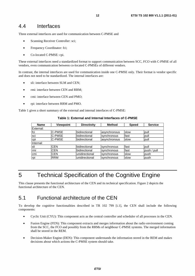
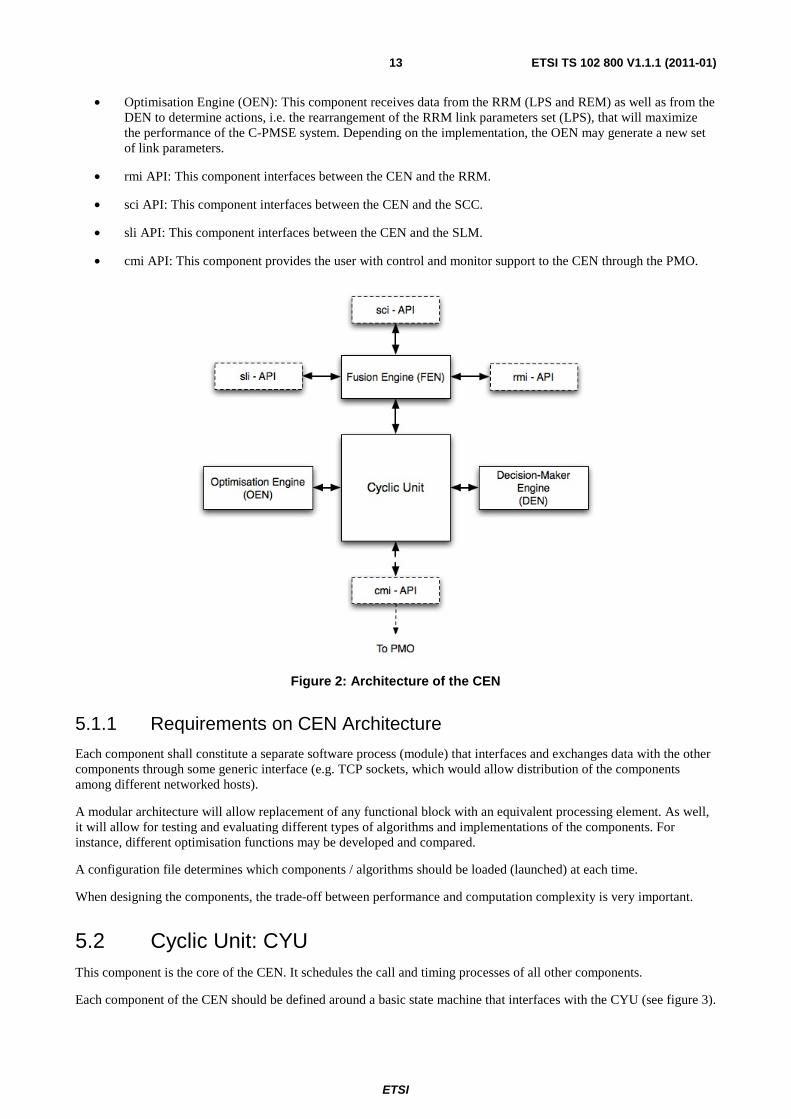


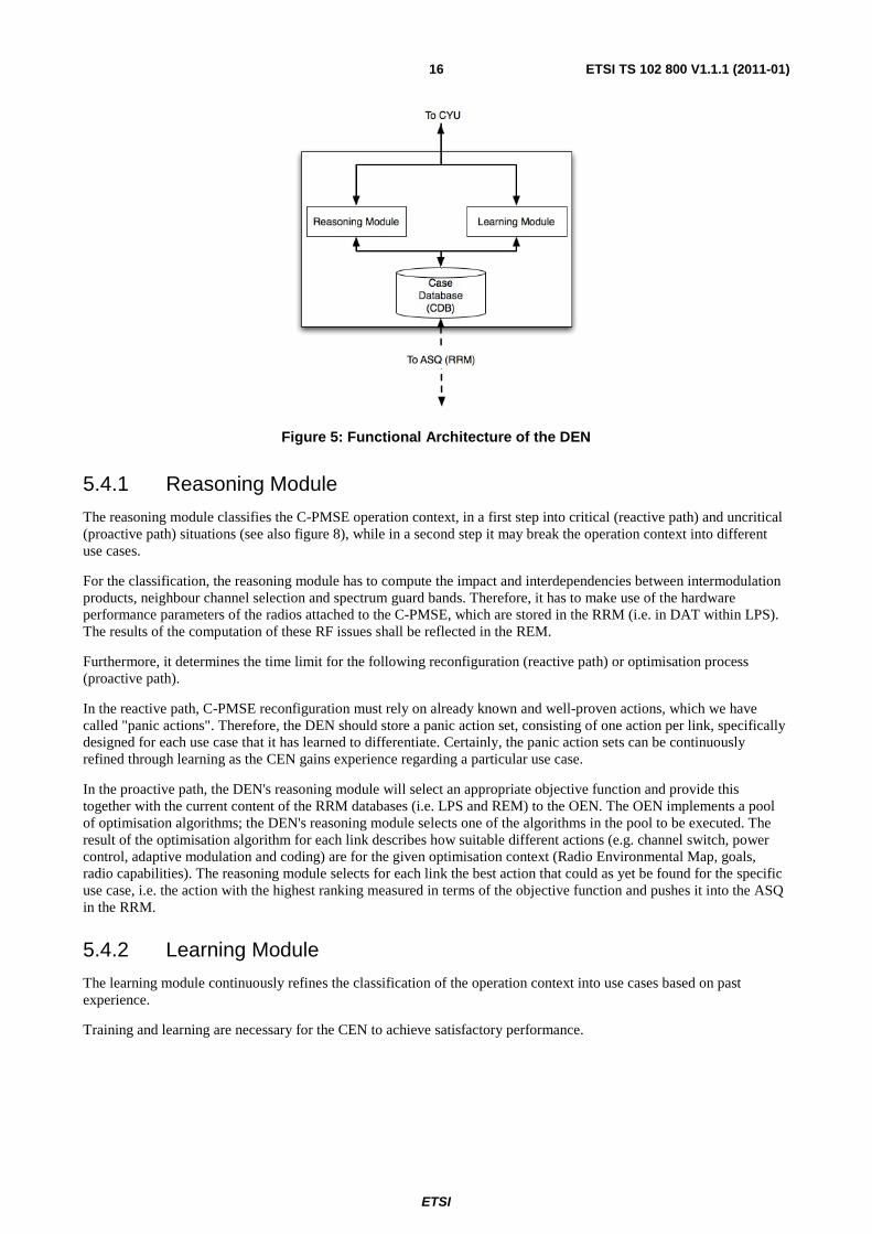
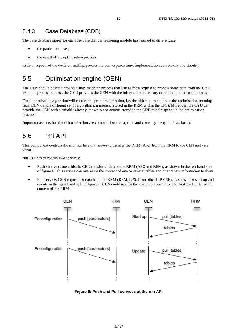


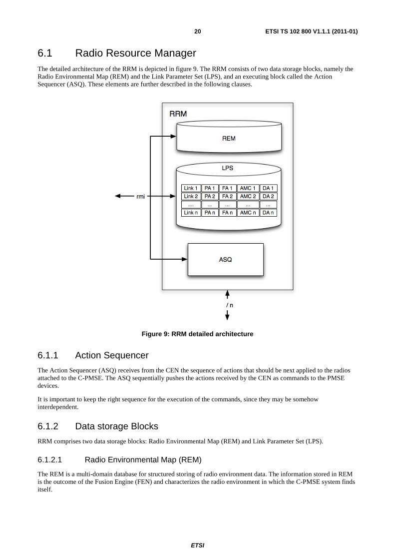

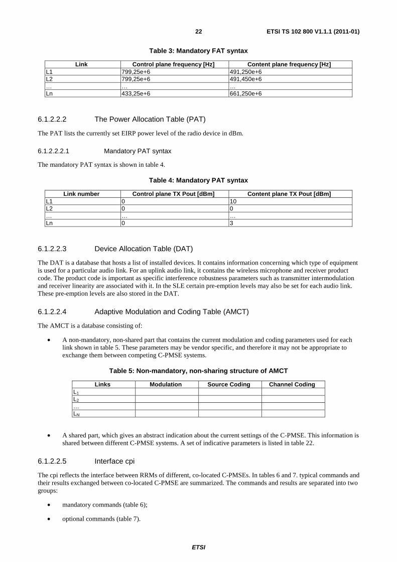
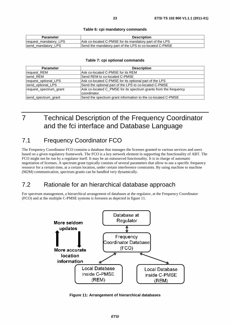

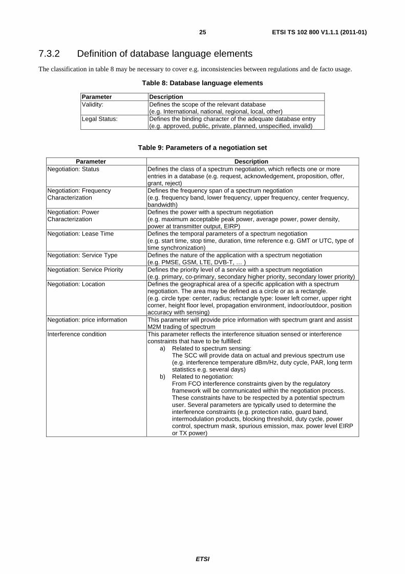

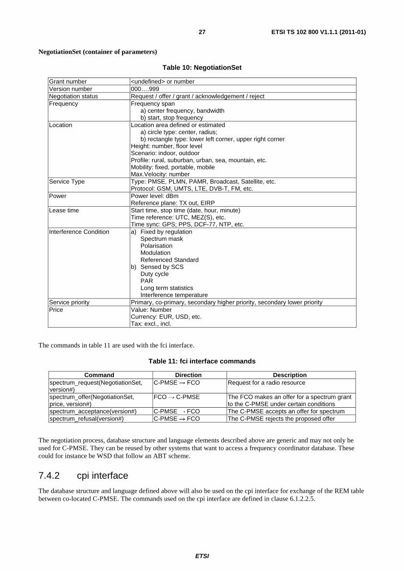


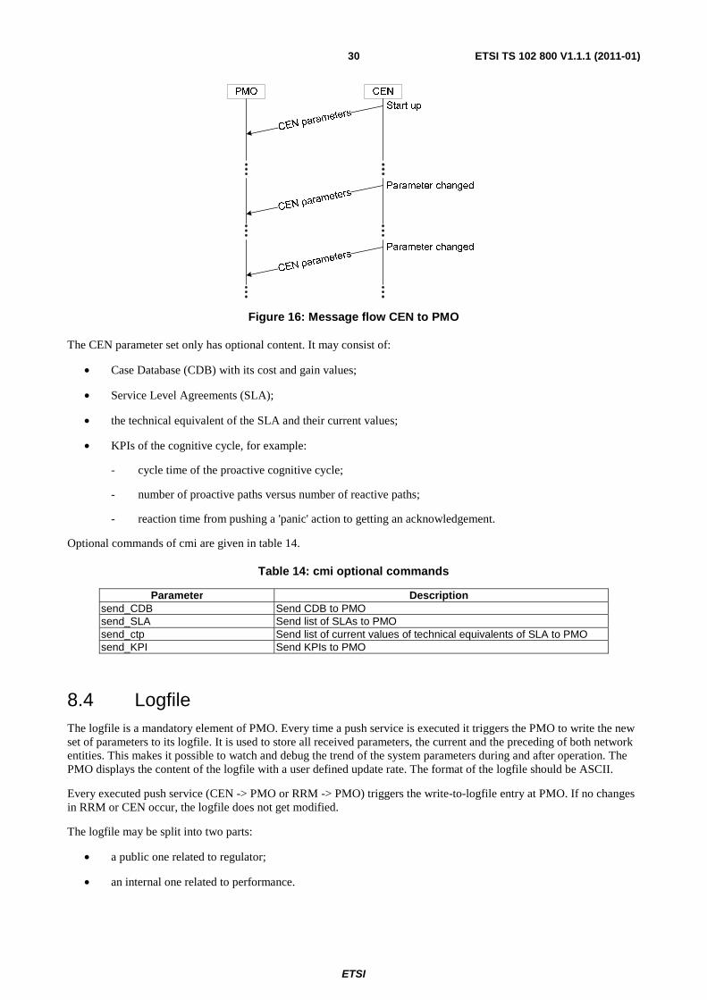

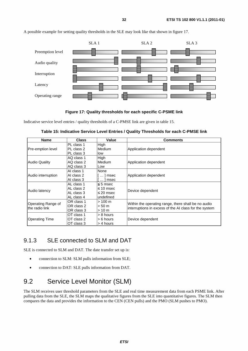
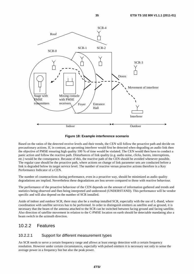

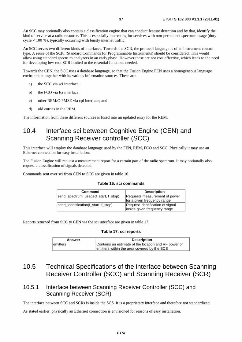

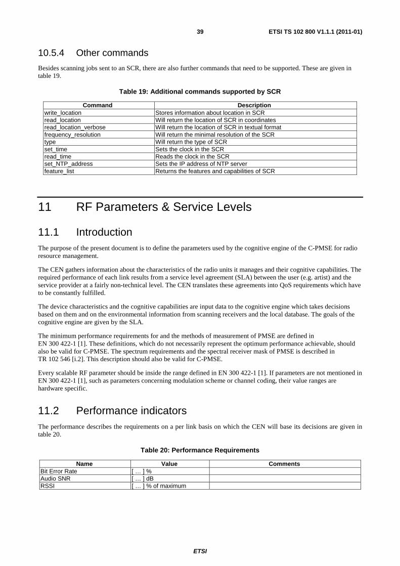
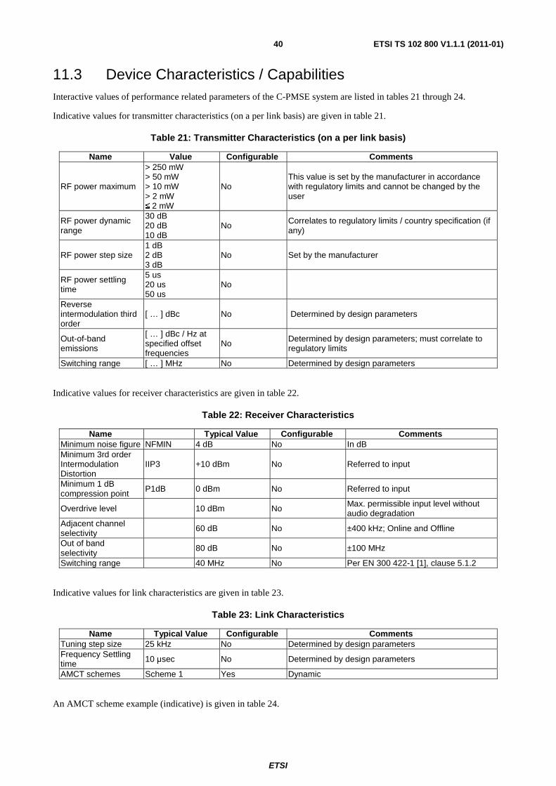
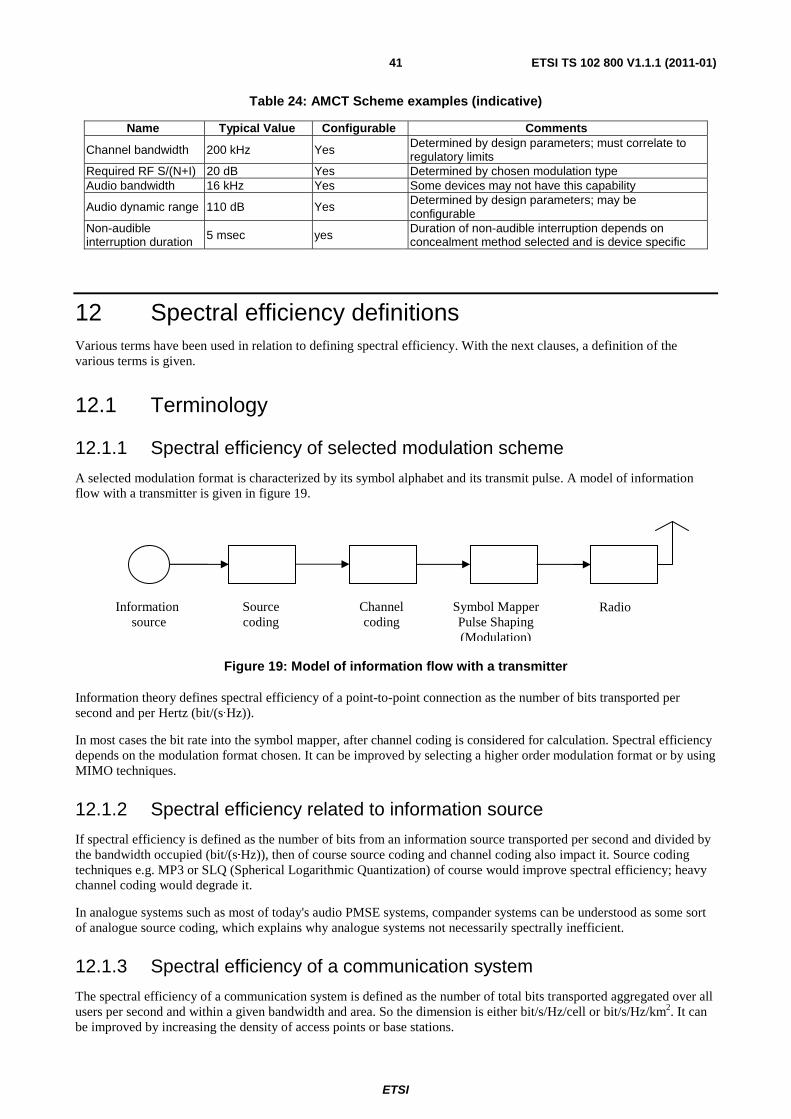


![TR 103 151 - V1.1.1 - Electromagnetic compatibility and ... · [i.2] ETSI TR 102 791: "Electromagnetic compatibility and Radio spectrum Matters ... AFIL Audio-Frequency Induction](https://static.documents.pub/doc/80x56/5ba13de809d3f2666b8bf159/tr-103-151-v111-electromagnetic-compatibility-and-i2-etsi-tr-102.jpg)


