IPv6 Transition Technology Engineering and Operational Aspects;
Part 3: DS-Lite
TECHNICAL SPECIFICATION
ETSI
ETSI TS 103 443-3 V1.1.1 (2016-08)2
Reference DTS/CABLE-00018-3
Keywords cable, HFC, IPv6
ETSI
650 Route des Lucioles F-06921 Sophia Antipolis Cedex - FRANCE
Tel.: +33 4 92 94 42 00 Fax: +33 4 93 65 47 16
Siret N° 348 623 562 00017 - NAF 742 C
Association à but non lucratif enregistrée à la Sous-Préfecture de Grasse (06) N° 7803/88
Important notice
The present document can be downloaded from: http://www.etsi.org/standards-search
The present document may be made available in electronic versions and/or in print. The content of any electronic and/or print versions of the present document shall not be modified without the prior written authorization of ETSI. In case of any
existing or perceived difference in contents between such versions and/or in print, the only prevailing document is the print of the Portable Document Format (PDF) version kept on a specific network drive within ETSI Secretariat.
Users of the present document should be aware that the document may be subject to revision or change of status. Information on the current status of this and other ETSI documents is available at
If you find errors in the present document, please send your comment to one of the following services: https://portal.etsi.org/People/CommiteeSupportStaff.aspx
Copyright Notification
No part may be reproduced or utilized in any form or by any means, electronic or mechanical, including photocopying and microfilm except as authorized by written permission of ETSI.
The content of the PDF version shall not be modified without the written authorization of ETSI. The copyright and the foregoing restriction extend to reproduction in all media.
DECTTM, PLUGTESTSTM, UMTSTM and the ETSI logo are Trade Marks of ETSI registered for the benefit of its Members. 3GPPTM and LTE™ are Trade Marks of ETSI registered for the benefit of its Members and
of the 3GPP Organizational Partners. GSM® and the GSM logo are Trade Marks registered and owned by the GSM Association.
Intellectual Property Rights ................................................................................................................................ 6
4.2 General Overview............................................................................................................................................. 14
5 Gap Analysis .......................................................................................................................................... 15
6.1 End to End Network Domains .......................................................................................................................... 16
6.6 Data Centre Network Domain .......................................................................................................................... 21
6.7 DMZ Service Domain ...................................................................................................................................... 21
6.8 Transit and Peering Service Domain ................................................................................................................ 21
6.9 Management and Monitoring Domain ............................................................................................................. 21
6.9.1 General Considerations ............................................................................................................................... 21
7.3.1.2 Type ...................................................................................................................................................... 28
7.3.5.1 General considerations .......................................................................................................................... 33
9 Support Systems ..................................................................................................................................... 36
10.1.2.1 General .................................................................................................................................................. 39
10.1.2.5 Software Features .................................................................................................................................. 40
10.1.2.5.8 DNS over IPv6 ................................................................................................................................ 41
10.1.2.5.9 Port Forwarding ............................................................................................................................... 41
10.1.2.5.10 SI ..................................................................................................................................................... 41
10.1.2.5.14 Customer Management (Access and Reporting) ............................................................................. 42
10.1.2.5.15 Cable Operators Corporate Management (IPv6 or IPv4) ................................................................ 42
10.1.2.5.16 Port Forwarding ............................................................................................................................... 42
10.1.2.6.3 Max sessions .................................................................................................................................... 43
10.1.2.7.1 General ............................................................................................................................................ 43
10.1.2.7.2 WAN requirements: ......................................................................................................................... 43
10.2.1 DHCPv6 - PD Internal and external ........................................................................................................... 44
10.3 DNS over IPv6 ................................................................................................................................................. 44
10.7 Placement of function on LSN or CPE ............................................................................................................. 45
History .............................................................................................................................................................. 48
ETSI
ETSI TS 103 443-3 V1.1.1 (2016-08)6
Intellectual Property Rights
IPRs essential or potentially essential to the present document may have been declared to ETSI. The information pertaining to these essential IPRs, if any, is publicly available for ETSI members and non-members, and can be found in ETSI SR 000 314: "Intellectual Property Rights (IPRs); Essential, or potentially Essential, IPRs notified to ETSI in respect of ETSI standards", which is available from the ETSI Secretariat. Latest updates are available on the ETSI Web server (https://ipr.etsi.org/).
Pursuant to the ETSI IPR Policy, no investigation, including IPR searches, has been carried out by ETSI. No guarantee can be given as to the existence of other IPRs not referenced in ETSI SR 000 314 (or the updates on the ETSI Web server) which are, or may be, or may become, essential to the present document.
Foreword
This Technical Specification (TS) has been produced by ETSI Technical Committee TC CABLE.
The present document is part 3 of a multi-part deliverable. Full details of the entire series can be found in part 1 [34].
Modal verbs terminology In the present document "shall", "shall not", "should", "should not", "may", "need not", "will", "will not", "can" and "cannot" are to be interpreted as described in clause 3.2 of the ETSI Drafting Rules (Verbal forms for the expression of provisions).
"must" and "must not" are NOT allowed in ETSI deliverables except when used in direct citation.
Introduction Considering the depletion of IPv4 addresses, transition to IPv6 is required in order to enable continued growth of the customer base connected to cable networks and ensure service continuity for existing and new customers. High-quality connectivity to all kinds of IP-based services and networks is essential in today's business and private life.
The present document accommodates an urgent need in the industry to implement and integrate the IPv6 transition technologies as specified by ETSI TS 101 569-1 [1] into their cable networks. The choice of the technology implemented depends on factors such as the business needs, current deployed architectures and plans for cost effectively transition from IPv4 to IPv6.
Current global IPv4 address space was projected to be depleted around the middle of 2012; depletion for the operator was estimated around end 2012. As part of the resulting roll-out of IPv6 in the operator's network, specific measures had to be taken to allow a smooth transition and coexistence between IPv4 and IPv6. ETSI developed requirements to address transition from IPv4 to IPv6 specifying six transition technologies as given by ETSI TS 101 569-1 [1] that were at the time considered to be the most appropriate to assist cable operators to transition there cable networks to IPv6.
Since then the industry has acquired more experience with the technology options settling in the main for DS-Lite across the cable network market and NAT64 IPv6 transition technologies across the mobile market.
The objective of the present document is to define the operational and engineering requirements to enable engineers to implement a seamless transition of the cable networks to IPv6 with the application of the DS-Lite transition technology.
The present document is the final part of a companion of ETSI standards developed in 4 phases to provide the cable sector in particular cable operators engineering and operational staff a standardized approach when integrating one of the five IPv6 transition technologies, NAT64, DS-Lite, 464XLAT, 6RD and MAP-E.
The first phase assessed the different IPv6 transition technology options being defined by industry with recommendation for the most appropriate with consideration of current network architectures, ensuring adequate scale and a cost effective transition approach from IPv4 to IPv6 as the IPv4 addresses deplete. The objective being to examine the pros and cons of the IPv6 transition technologies and recommend the most cost effective solution that would enable the cable operators to minimize the cost of upgrades to their existing network plant whilst maintain continuity of services to their present and new added customers. The details of the study are given by ETSI TR 101 569 [i.5].
In the second phase an ETSI technical specification was developed to specify technical requirements for six transition technologies that industry were considering for use by Cable Operators depending on the current state of their deployed cable network architecture, service model requirements and their IPv6 transition strategy as the IPv4 addresses depleted. These six IPv6 transition technologies are specified by ETSI TS 101 569-1 [1], covering NAT64, DS-Lite, 6RD, NAT44, 464XLAT and MAP-E.
In the third phase ETSI developed a series of conformance test specifications to enable the compliance verification of the five IPv6 transition technologies, NAT64, DS-Lite, 464XLAT, 6RD and MAP-E that were specified during phase 2 standardization. The conformance tests are developed against the requirements given by the ETSI TS 101 569-1 [1]. The series of conformance tests developed for each of the four transition technologies, are as given by ETSI TS 103 238 parts 1 [2] to 3 [4] respectively for NAT64; ETSI TS 103 239 parts 1 [5] to 3 [7] respectively for MAP-E; ETSI TS 103 241 parts 1 [8] to 3 [10] respectively for DS-Lite; ETSI TS 103 242 parts 1 [11] to 3 [13] respectively for XLAT and ETSI TS 103 243 parts 1 [14] to 3 [16] respectively for 6RD.
Phase 4 is the present project phase for development of technical specifications covering the operational and engineering requirements with the present document being part 3 of a multi-part series covering the IPv6 transition technology DS-Lite.
DOCSIS® is a registered Trade Mark of Cable Television Laboratories, Inc., and is used in the present document with permission.
ETSI
ETSI TS 103 443-3 V1.1.1 (2016-08)8
1 Scope
The present document presents the engineering and operational requirements for the application of the IPv6 transition technology DS-Lite as defined by ETSI TS 101 569-1 [1] (IPv6 Transition Requirements) implemented within an integrated broadband cable network end to end across its network domains.
The present document is part 3 of a multi-part series and presents the operational aspects of the IPv6 transition technology DS-Lite across the cable network domains.
Only those elements of the network that have to be engineered to operate the IPv6 transition technology DS-Lite are presented. Descriptions and interface details of network elements that do not change are already addressed by the relevant equipment cable standards and therefore this information is not included in the present document.
The conformity of the DS-Lite implementation is relevant when assessing its implementation and operational requirements across the cable network to ensure the implementation is correctly engineered to conform to the requirements of the base standard ETSI TS 101 569-1 [1]. These conformance tests are not specified in the present document as they are already specified by ETSI TS 103 241 parts 1 to 3 [8], [9] and [10].
The operational aspects for the IPv6 transition technology DS-Lite are considered when engineered end to end across the cable network domains:
• CPE Home Networking Domain
• Access Network Domain
• Core Network Domain
• Data Center Domain
• DMZ Service Domain
• Transit and Peering Domain
• Management and Monitoring Domain
• Security Domain
The present document specifies the requirements to be considered when the defined IPv6 transition technology DS-Lite is engineered across the cable network domains.
2 References
2.1 Normative references
References are either specific (identified by date of publication and/or edition number or version number) or non-specific. For specific references, only the cited version applies. For non-specific references, the latest version of the referenced document (including any amendments) applies.
Referenced documents which are not found to be publicly available in the expected location might be found at http://docbox.etsi.org/Reference.
NOTE: While any hyperlinks included in this clause were valid at the time of publication, ETSI cannot guarantee their long term validity.
The following referenced documents are necessary for the application of the present document.
[1] ETSI TS 101 569-1: "Integrated Broadband Cable Telecommunication Networks (CABLE); Cable Network Transition to IPv6 Part 1: IPv6 Transition Requirements".
[2] ETSI TS 103 238-1: "Integrated broadband cable telecommunication networks (CABLE); Testing; Conformance test specifications for NAT64 technology; Part 1: Protocol Implementation Conformance Statement (PICS) proforma".
[3] ETSI TS 103 238-2: "Integrated broadband cable telecommunication networks (CABLE); Testing; Conformance test specifications for NAT64 technology; Part 2: Test Suite Structure and Test Purposes (TSS&TP)".
[4] ETSI TS 103 238-3: "Integrated broadband cable telecommunication networks (CABLE); Testing; Conformance test specifications for NAT64 technology; Part 3: Abstract Test Suite (ATS) and Protocol Implementation eXtra Information for Testing (PIXIT)".
[5] ETSI TS 103 239-1: "Integrated broadband cable telecommunication networks (CABLE); Testing; Conformance test specifications for MAP-E technology; Part 1: Protocol Implementation Conformance Statement (PICS) proforma".
[6] ETSI TS 103 239-2: "Integrated broadband cable telecommunication networks (CABLE); Testing; Conformance test specifications for MAP-E technology; Part 2: Test Suite Structure and Test Purposes (TSS&TP)".
[7] ETSI TS 103 239-3: "Integrated broadband cable telecommunication networks (CABLE); Testing; Conformance test specifications for MAP-E technology; Part 3: Abstract Test Suite (ATS) and Protocol Implementation eXtra Information for Testing (PIXIT)".
[8] ETSI TS 103 241-1: "Integrated broadband cable telecommunication networks (CABLE); Testing; Conformance test specifications for DS-Lite technology; Part 1: Protocol Implementation Conformance Statement (PICS) proforma".
[9] ETSI TS 103 241-2: "Integrated broadband cable telecommunication networks (CABLE); Testing; Conformance test specifications for DS-Lite technology; Part 2: Test Suite Structure and Test Purposes (TSS&TP)".
[10] ETSI TS 103 241-3: "Integrated broadband cable telecommunication networks (CABLE); Testing; Conformance test specifications for DS-Lite technology; Part 3: Abstract Test Suite (ATS) and Protocol Implementation eXtra Information for Testing (PIXIT)".
[11] ETSI TS 103 242-1: "Integrated broadband cable telecommunication networks (CABLE); Testing; Conformance test specifications for 464XLAT technology; Part 1: Protocol Implementation Conformance Statement (PICS) proforma".
[12] ETSI TS 103 242-2: "Integrated broadband cable telecommunication networks (CABLE) Testing; Conformance test specifications for 464XLAT technology; Part 2: Test Suite Structure and Test Purposes (TSS&TP)".
[13] ETSI TS 103 242-3: "Integrated broadband cable telecommunication networks (CABLE); Testing; Conformance test specifications for 464XLAT technology; Part 3: Abstract Test Suite (ATS) and Protocol Implementation eXtra Information for Testing (PIXIT)".
[14] ETSI TS 103 243-1: "Integrated broadband cable telecommunication networks (CABLE); Testing; Conformance test specifications for 6rd technology; Part 1: Protocol Implementation Conformance Statement (PICS) proforma".
[15] ETSI TS 103 243-2: "Integrated broadband cable telecommunication networks (CABLE); Testing; Conformance test specifications for 6rd technology; Part 2: Test Suite Structure and Test Purposes (TSS&TP)".
[16] ETSI TS 103 243-3: "Integrated broadband cable telecommunication networks (CABLE); Testing; Conformance test specifications for 6rd technology; Part 3: Abstract Test Suite (ATS) and Protocol Implementation eXtra Information for Testing (PIXIT)".
[17] IETF RFC 6333 (August 2011): "Dual-Stack Lite Broadband Deployments Following IPv4 Exhaustion".
[18] IETF RFC 4459 (April 2006): "MTU and Fragmentation Issues with In-the-Network Tunneling".
[25] CableLabs CM-SP-OSSIv3.0-I21-130404: "Operations Support System Interface Specification".
[26] ETSI EN 302 878-4: "Access, Terminals, Transmission and Multiplexing (ATTM); Third Generation Transmission Systems for Interactive Cable Television Services - IP Cable Modems; Part 4: MAC and Upper Layer Protocols; DOCSIS 3.0".
[27] CableLabs CM-SP-eRouter-I18-160317: "IPv4 and IPv6 eRouter Specification".
[28] IETF RFC 4361 (February 2006): "Node-specific Client Identifiers for Dynamic Host Configuration Protocol Version Four (DHCPv4)".
[29] Broadband Forum Technical Report TR-069 (November 2013): "CPE WAN Management Protocol v1, Issue 1, Amendment 5".
[30] IETF RFC 3646 (December 2003): "DNS Configuration options for Dynamic Host Configuration Protocol for IPv6 (DHCPv6)".
[31] IETF RFC 6092 (January 2011): "Recommended Simple Security Capabilities in Customer Premises Equipment (CPE) for Providing Residential IPv6 Internet Service".
[32] IETF RFC 2872 (June 2000): "Application and Sub Application Identity Policy Element for use with RSVP".
[34] ETSI TS 103 443-1: "Integrated broadband cable telecommunication networks (CABLE); IPv6 Transition Technology Engineering and Operational Aspects; Part 1: General".
[35] IEEE 802.11n-2009™: "IEEE Standard for Information technology-- Local and metropolitan area networks-- Specific requirements-- Part 11: Wireless LAN Medium Access Control (MAC)and Physical Layer (PHY) Specifications Amendment 5: Enhancements for Higher Throughput".
[36] IEEE 802.11g-2003™: "IEEE Standard for Information technology-- Local and metropolitan area networks-- Specific requirements-- Part 11: Wireless LAN Medium Access Control (MAC) and Physical Layer (PHY) Specifications: Further Higher Data Rate Extension in the 2.4 GHz Band".
[37] IEEE 802.3-2015™: "IEEE Standard for Ethernet".
[38] IEEE 802.3u-1995™: "IEEE Standards for Local and Metropolitan Area Networks-Supplement - Media Access Control (MAC) Parameters, Physical Layer, Medium Attachment Units and Repeater for 100Mb/s Operation, Type 100BASE-T (Clauses 21-30)".
[39] IETF RFC 6106: "IPv6 Router Advertisement Options for DNS Configuration".
[40] draft-ietf-pcp-base-12: "Port Control Protocol (PCP)".
[41] draft-ietf-pcp-base-13: "Port Control Protocol (PCP)".
[42] draft-ietf-pcp-base-29: "Port Control Protocol (PCP)".
ETSI
ETSI TS 103 443-3 V1.1.1 (2016-08)11
2.2 Informative references
References are either specific (identified by date of publication and/or edition number or version number) or non-specific. For specific references, only the cited version applies. For non-specific references, the latest version of the referenced document (including any amendments) applies.
NOTE: While any hyperlinks included in this clause were valid at the time of publication, ETSI cannot guarantee their long term validity.
The following referenced documents are not necessary for the application of the present document but they assist the user with regard to a particular subject area.
[i.1] CableLabs.
NOTE: Available at http://www.cablelabs.com/specs/.
[i.2] IETF RFC 1918: "Address Allocation for Private Internets".
[i.3] draft-ietf-softwire-dual-stack-lite-05: "Dual-Stack Lite Broadband Deployments Following IPv4 Exhaustion.
[i.4] draft-ietf-softwire-gateway-init-ds-lite-05: " Gateway Initiated Dual-Stack Lite Deployment".
[i.5] ETSI TR 101 569: "Access, Terminals, Transmission and Multiplexing (ATTM); Integrated Broadband Cable and Television Networks; Cable Network Transition to IPv6".
3 Definitions and abbreviations
3.1 Definitions For the purposes of the present document, the following terms and definitions apply:
4in6: encapsulation of IPv4 packets within IPv6 packet format
NAT44: network address translation from an IPv4 address to another IPv4 address
P Router: label switching router acting as a transit router in the core network of an MPLS network
3.2 Abbreviations For the purposes of the present document, the following abbreviations apply:
6PE IPv6 Provider Edge 6VPE IPv6 Virtual Private Network Provider Edge A+P Address + Port AAA Authentication, Authorization and Accounting ACL Access Control List AF Address Family AFTR Address Family Transition Router ALG Application Layer Gateway ALP Application-Level Proxy AMPS Amplifiers AS Autonomous System ASCII American Standard Code for Information Interchange ASIC Application Specific Integrated Circuit ATFR Address Family Transition Router AV Audio/Video B2B Business to Business B2C Business to Customer B4 Basic Bridging BroadBand element
BCP Best Current Practice BFD Bidirectional Forwarding Detection BGP Boarder Gateway Protocol BNG Broadband Network Gateway BW Bandwidth CPE customer premises equipment CDP Cisco Discovery Protocol CE Cable Edge CEF Cisco Express Forwarding CLI Command Line Interface CMTS Cable Modem Termination System CoPP Control Plane Policing CPE Customer Premise Equipment CPU Central Processing Unit DAD Duplicate Address Detection DB Data Base dCEF distributed Cisco Express Forwarding DCU Destination Class Usage DF Do not Fragment flag DHCP Dynamic Host Configuration DMZ De-Militarized Zone DNS Domain Name System DR Data Retention DSCP Differentiated Services Code Point DS-Lite Dual Stack-Lite DUID DHCP Unique Identifier ECMP Eqwual-Cost-Multi-Path ECN Explicit Congestion Notification EUI Extended Unique Identifier FQDN Fully Qualified Domain Name FTP File Transfer Protocol GW Gateway GB GigaByte GRT Global Routing Table GW GateWay HA High Availability HA High Availability HD High Definition HDCP typo; replace with DHCP HFC Hybrid Fibre Coax HSRP Hot Standby Router Protocol IANA Internet Assigned Numbers Authority ICMP Internet Control Message Protocol ID Identifier IE Internet Explorer (trade name) IGP Interior Gateway Protocol IMAP Internet Message Access Protocol IMIX Internet Mix IP Internet Protocol IPE Internal Provider Edge IP-FIX Internet Protocol Flow Information Export IPFIX IP Flow Information Export PPTP Point-to-Point Tunnelling Protocol IPSec IP Security IPv4 IP version 4 IPv6 IP version 6 IRC Internet Relay Chat ISA Intermediate System Architecture ISIS Intermediate System to Intermediate System ISSU In-Service Software Upgrade IXCF Internet Exchange Communication Function IX-PE Internet eXchange Provider Edge IXPE Internet Exchange Provider Edge LAN Local Area Network LB Load Balancing
ETSI
ETSI TS 103 443-3 V1.1.1 (2016-08)13
LDP Label Distribution Protocol LI Lawful Intercept LLDP Link Layer Discovery Protocol LSN Large Scale NAT MAC Medium Access Control MFIB Multicast Forwarding Information Base MIB Management Information Base MLD/L2 Multicast Listener Discovery/ Layer 2 MP BGP MultiProtocol Boarder Gateway Protocol MP Multi-Protocol MPLS MultiProtocol Label Switching MSS Maximum Segment Size MSTP Multiple Spanning Tree Protocol MT Multi-Topology MTU Maximum Transmission Unit NAT Network Address Translation NAT Network Address Translation NAT64 Network Address Translation IPv6 to IPv4 NAT-PMP Network Address Translation - Port Mapping Protocol NDP Neighbor Discovery Protocol NFv9 Netflow Version 9 NPU Network Processing Unit NSF/GR Non-Stop Forwarding Graceful Restart NTP Network Time Protocol NUD Neigbor Unreachability Detection OAM Operation, Administration and Maintenance OSS Operations Support System PC Personal Computer PCP Port Control Protocol PD Prefix Delegation PE Provider Edge PHY Physical Layer PIM Protocol Independent Multicasting PMP Port Mapping Protocol PPTP Point-to-Point Tunnelling Protocol PS-BGP Pretty Secure Boarder Gateway Protocol PVST Per VLAN Spanning Tree QoS Quality of Service QPPB QoS Policy Propagation via Boarder Gateway Protocol RA Router Advertisement RADIUS Remote Authentication Dial-In User Service RDP Remote Desktop Protocol RDT Reliable Data Transfer RG Residential Gateway RP Route Processor RSTP Rapid Spanning Tree Protocol RTCP Real-Time Transmission Control Protocol RTP Real-Time Protocol RTSP Real-Time Streaming Protocol SCU Source Class Usage SEND Secure Neighbor Discovery SI Softwire Initiation SI-ID Softwire Initiator Identifier SIP Session Initiated Protocol SLAAC StaLess Address Auto Configuration SMTP Simple Mail Transfer Protocol SNMP Simple Network Management Protocol SPI Stateful Packet Inspection SSH Secure SHell SSHD Secure SHell Demon SSL Secure Socket Layer SSO Stateful Switchover
ETSI
ETSI TS 103 443-3 V1.1.1 (2016-08)14
STUN Session Traversal Utilities for NAT SVI Switch Virtual Interface TACACS Terminal Access Controller Access Control System TCP Transmission Control Protocol TFTP Trivial File Transfer Protocol UDP User Datagram Protocol UI User Interface UPnP Universal Plug and Play USB Universal Serial Bus VLAN Virtual Local Area Network VPLS Virtual Protocol Local Area Network Service VPN Virtual Private Network VRF Virtual Routing and Forwarding VRRP Virtual Router Redundancy Protocol WAN Wide Area Network Web-UI Website - User Interface WEP Wired Equivalent Privacy WPA Wi-Fi Protected Access XLAT transLATor XML eXtensible Markup Language
4 Considerations
4.1 Background The present technical specification is part of a series of ETSI technical specifications specifying requirements to engineer and operate the DS-Lite transition technology end to end across a cable operator's network. Its implementation would ensure the network provider can continue to provide business continuity throughout the depletion of publicly routable IPv4 addresses and the subsequent rollout and migration to IPv6 in the operator's network.
To aid this transition the industry is currently procuring Dual Stack-Lite (DS-Lite) and NAT64 as the chosen technologies to mitigate the gap and lack of integration and compatibility between IPv4 and IPv6.
4.2 General Overview The present document covers the DS-Lite, AFTR and CPE functions required to be engineered and operated within the operator's network footprint.
DS-Lite will allow customers to access services natively over IPv6 and through translation over IPv4. As IPv6 does not have "backward compatibility" to IPv4 and the two protocols know nothing of each other's existence in most topologies, DS-Lite is needed to allow for a smooth transition towards IPv6 once no more IPv4 addresses are available. DS-Lite also allows for the new "IPv6 only" services to be accessed by the subscriber with little to no deprecation on IPv4 services.
An objective of deploying the IPv6 transition technology is to provide a seamless experience to users accessing IPv4 network services through new IPv6 only networks and to enable current and new content to be delivered seamlessly to IPv6 users by deploying DS-Lite.
It should be noted that Cable broadband access networks may vary in build and design with some network characteristics are dependent on the deployed vender proprietary equipment. Consequently there may be aspects to the engineering and operation of the IPv6 transiti.on technology DS-Lite that are dependent on the historical network build and vendor specific equipment deployed.
The present document does not offer information that may be vendor and network build specific since such information may be confidential to the network operator and/or based on proprietary standards.
ETSI
ETSI TS 103 443-3 V1.1.1 (2016-08)15
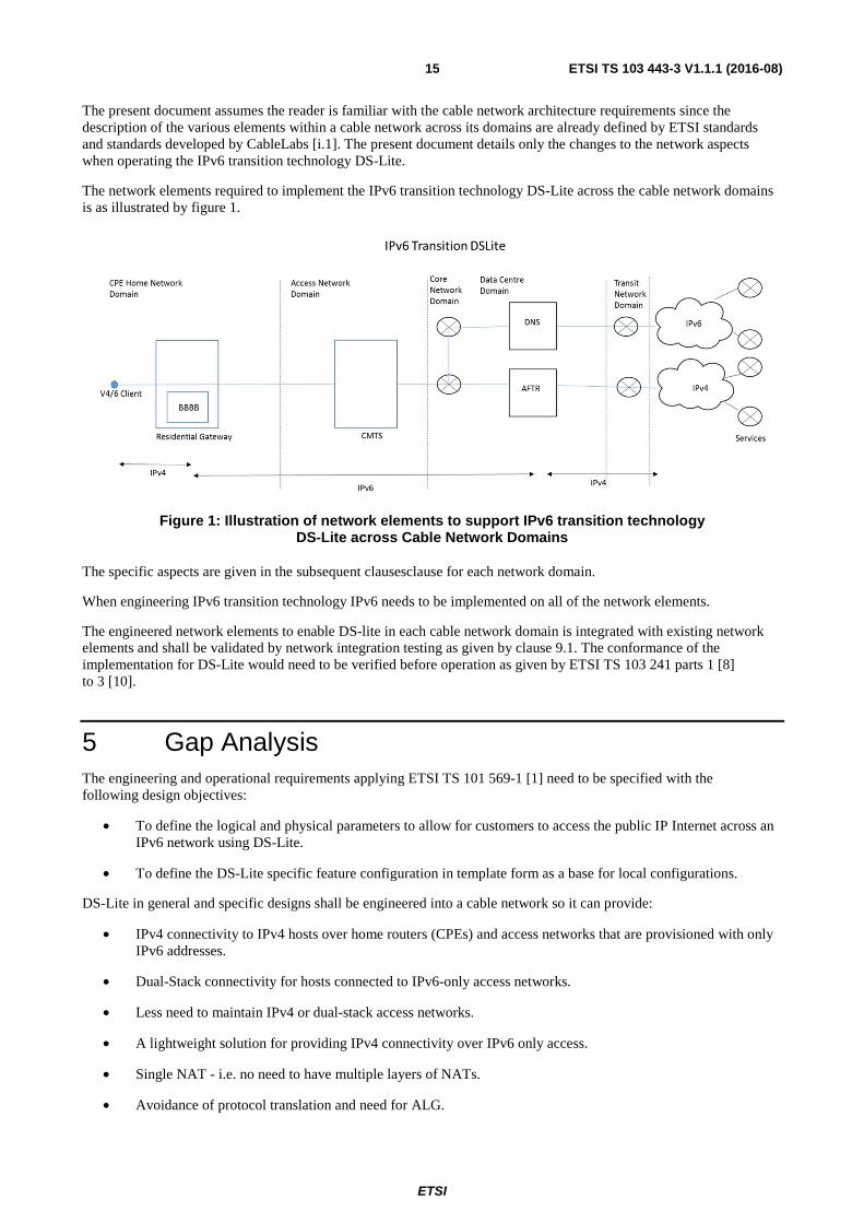
The present document assumes the reader is familiar with the cable network architecture requirements since the description of the various elements within a cable network across its domains are already defined by ETSI standards and standards developed by CableLabs [i.1]. The present document details only the changes to the network aspects when operating the IPv6 transition technology DS-Lite.
The network elements required to implement the IPv6 transition technology DS-Lite across the cable network domains is as illustrated by figure 1.
Figure 1: Illustration of network elements to support IPv6 transition technology DS-Lite across Cable Network Domains
The specific aspects are given in the subsequent clausesclause for each network domain.
When engineering IPv6 transition technology IPv6 needs to be implemented on all of the network elements.
The engineered network elements to enable DS-lite in each cable network domain is integrated with existing network elements and shall be validated by network integration testing as given by clause 9.1. The conformance of the implementation for DS-Lite would need to be verified before operation as given by ETSI TS 103 241 parts 1 [8] to 3 [10].
5 Gap Analysis The engineering and operational requirements applying ETSI TS 101 569-1 [1] need to be specified with the following design objectives:
• To define the logical and physical parameters to allow for customers to access the public IP Internet across an IPv6 network using DS-Lite.
• To define the DS-Lite specific feature configuration in template form as a base for local configurations.
DS-Lite in general and specific designs shall be engineered into a cable network so it can provide:
• IPv4 connectivity to IPv4 hosts over home routers (CPEs) and access networks that are provisioned with only IPv6 addresses.
• Dual-Stack connectivity for hosts connected to IPv6-only access networks.
• Less need to maintain IPv4 or dual-stack access networks.
• A lightweight solution for providing IPv4 connectivity over IPv6 only access.
• Single NAT - i.e. no need to have multiple layers of NATs.
• Avoidance of protocol translation and need for ALG.
ETSI
ETSI TS 103 443-3 V1.1.1 (2016-08)16
• Multiplexing public IPv4 addresses for large number of customers.
• Automatic tunnel establishment to tunnel endpoint (AFTR).
• Port forwarding capability on the AFTR using technologies such as: Web-UI, NAT-PMP, UPnP, A+P.
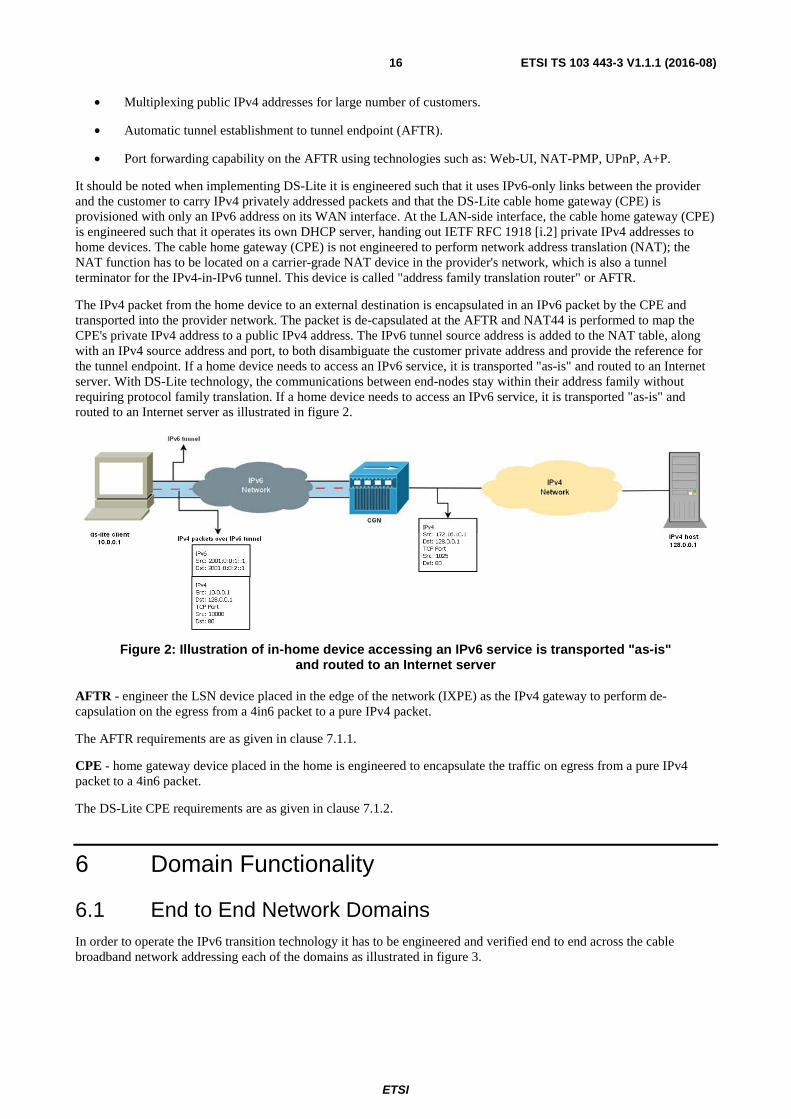
It should be noted when implementing DS-Lite it is engineered such that it uses IPv6-only links between the provider and the customer to carry IPv4 privately addressed packets and that the DS-Lite cable home gateway (CPE) is provisioned with only an IPv6 address on its WAN interface. At the LAN-side interface, the cable home gateway (CPE) is engineered such that it operates its own DHCP server, handing out IETF RFC 1918 [i.2] private IPv4 addresses to home devices. The cable home gateway (CPE) is not engineered to perform network address translation (NAT); the NAT function has to be located on a carrier-grade NAT device in the provider's network, which is also a tunnel terminator for the IPv4-in-IPv6 tunnel. This device is called "address family translation router" or AFTR.
The IPv4 packet from the home device to an external destination is encapsulated in an IPv6 packet by the CPE and transported into the provider network. The packet is de-capsulated at the AFTR and NAT44 is performed to map the CPE's private IPv4 address to a public IPv4 address. The IPv6 tunnel source address is added to the NAT table, along with an IPv4 source address and port, to both disambiguate the customer private address and provide the reference for the tunnel endpoint. If a home device needs to access an IPv6 service, it is transported "as-is" and routed to an Internet server. With DS-Lite technology, the communications between end-nodes stay within their address family without requiring protocol family translation. If a home device needs to access an IPv6 service, it is transported "as-is" and routed to an Internet server as illustrated in figure 2.
Figure 2: Illustration of in-home device accessing an IPv6 service is transported "as-is" and routed to an Internet server
AFTR - engineer the LSN device placed in the edge of the network (IXPE) as the IPv4 gateway to perform de-capsulation on the egress from a 4in6 packet to a pure IPv4 packet.
The AFTR requirements are as given in clause 7.1.1.
CPE - home gateway device placed in the home is engineered to encapsulate the traffic on egress from a pure IPv4 packet to a 4in6 packet.
The DS-Lite CPE requirements are as given in clause 7.1.2.
6 Domain Functionality
6.1 End to End Network Domains In order to operate the IPv6 transition technology it has to be engineered and verified end to end across the cable broadband network addressing each of the domains as illustrated in figure 3.
ETSI
ETSI TS 103 443-3 V1.1.1 (2016-08)17
Figure 3: Illustration of the Cable Broadband Network Domains
The tests described in table 1 shall be performed in the environments with the laboratory topologies, network integration and standalone. See clause 9.1.
6.2 DS-Lite Domain Topologies This clause explains the potential DS-Lite domain topologies.
NOTE: At the time of writing the present document, two topologies are possible, the integrated topology and the hairpin topology; however, depending on future hardware and software developments, additional topologies may be introduced.
The integrated topology as illustrated by figure 4 is the most flexible and as with the hairpin topology, figure 5, the use of an IGP is required and it will not allow to connect the AFTR anywhere on the core to any PE without running BGP in the core.
To support the hairpin topology P-routers may need to be converted into PE-routers or additional PE-router devices may need to be deployed in order to distribute the AFTR's as required.
In the integrated topology the AFTR would function as a full MPLS 6PE router.
ETSI
ETSI TS 103 443-3 V1.1.1 (2016-08)18
Figure 4: DS-Lite Dynamic Country Network Topology
In the hairpin topology as illustrated by figure 5, the AFTR functions as L3 router, hair-pinning connections through an external 6PE router. This topology should only be used when application of the integrated topology is not possible.
ETSI
ETSI TS 103 443-3 V1.1.1 (2016-08)19
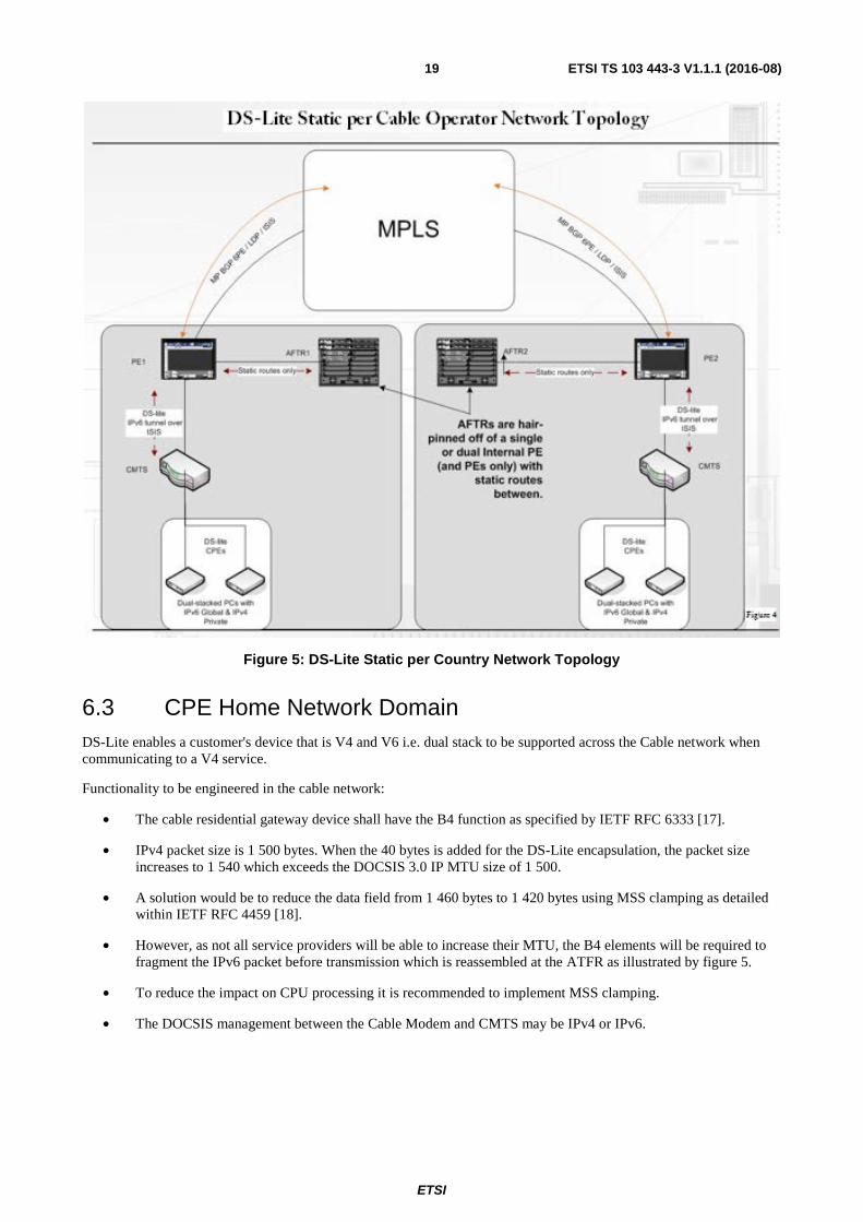
Figure 5: DS-Lite Static per Country Network Topology
6.3 CPE Home Network Domain DS-Lite enables a customer's device that is V4 and V6 i.e. dual stack to be supported across the Cable network when communicating to a V4 service.
Functionality to be engineered in the cable network:
• The cable residential gateway device shall have the B4 function as specified by IETF RFC 6333 [17].
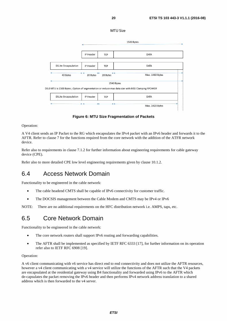
• IPv4 packet size is 1 500 bytes. When the 40 bytes is added for the DS-Lite encapsulation, the packet size increases to 1 540 which exceeds the DOCSIS 3.0 IP MTU size of 1 500.
• A solution would be to reduce the data field from 1 460 bytes to 1 420 bytes using MSS clamping as detailed within IETF RFC 4459 [18].
• However, as not all service providers will be able to increase their MTU, the B4 elements will be required to fragment the IPv6 packet before transmission which is reassembled at the ATFR as illustrated by figure 5.
• To reduce the impact on CPU processing it is recommended to implement MSS clamping.
• The DOCSIS management between the Cable Modem and CMTS may be IPv4 or IPv6.
ETSI
ETSI TS 103 443-3 V1.1.1 (2016-08)20
Figure 6: MTU Size Fragmentation of Packets
Operation:
A V4 client sends an IP Packet to the RG which encapsulates the IPv4 packet with an IPv6 header and forwards it to the AFTR. Refer to clause 7 for the functions required from the core network with the addition of the ATFR network device.
Refer also to requirements in clause 7.1.2 for further information about engineering requirements for cable gateway device (CPE).
Refer also to more detailed CPE low level engineering requirements given by clause 10.1.2.
6.4 Access Network Domain Functionality to be engineered in the cable network:
• The cable headend CMTS shall be capable of IPv6 connectivity for customer traffic.
• The DOCSIS management between the Cable Modem and CMTS may be IPv4 or IPv6
NOTE: There are no additional requirements on the HFC distribution network i.e. AMPS, taps, etc.
6.5 Core Network Domain Functionality to be engineered in the cable network:
• The core network routers shall support IPv6 routing and forwarding capabilities.
• The AFTR shall be implemented as specified by IETF RFC 6333 [17], for further information on its operation refer also to IETF RFC 6908 [19].
Operation:
A v6 client communicating with v6 service has direct end to end connectivity and does not utilize the AFTR resources, however a v4 client communicating with a v4 service will utilize the functions of the AFTR such that the V4 packets are encapsulated at the residential gateway using B4 functionality and forwarded using IPv6 to the AFTR which de-capsulates the packet removing the IPv6 header and then performs IPv4 network address translation to a shared address which is then forwarded to the v4 server.
ETSI
ETSI TS 103 443-3 V1.1.1 (2016-08)21
The communication between the AFTR and V4 server for the session will be using v4 packets, whereas the communication between the v4 client and AFTR is encapsulated in IPv6 so this enables the V4 client to communicate to a V4 service with the AFTR maintaining the state of the session.
Refer also to requirements in clauses 7.1.1 and 7.3 for general and detailed AFTR engineering requirements and to clauses 10.4, 10.5 and 10.6.
6.6 Data Centre Network Domain Functionality to be engineered in the cable network:
There are no changes to the network DNS functionality required. The DNS shall be IPv6 capable.
The DHCP server is inherently IPv6 only and shall include DHCP option for DSLite as specified in IETF RFC 6334 [20].
Refer also to clause 11.2 for further information about engineering of DHCP requirements.
6.7 DMZ Service Domain Functionality to be engineered in the cable network.
There are no specific operational requirements for the DMZ however it is strongly recommended that all services within the DMZ are IPv6 capable either by dual stack configuration or the use of V6/V4 load balancing.
V6/V4 load balancers allow V6 access to existing v4 services such as a web server avoiding the need to engineer v6 only content on these servers.
To minimize the impact on the AFTR from having to perform encapsulations on the received IPv4 packets for the network providers own services then all services within the DMZ shall be IPv6 capable.
6.8 Transit and Peering Service Domain Functionality to be engineered in the cable network.
There are no changes to be engineered when considering the transit and peering domain since the transmit and peering links are dual stack and support both IPv6 and IPv4 packets simultaneously and therefore no specific additional requirements are needed to be defined for this domain.
6.9 Management and Monitoring Domain
6.9.1 General Considerations
Functionality to be engineered in the cable network.
DOCSIS management between the CMTS and Cable Modem may remain deployed either using IPv4 or IPv6 addresses.
There is the additional functionality to monitor and manage the Cable Modem B4 functionality. Similarly to manage the monitor the ATFR in order to provide sufficient capacity to scale with the traffic throughput. Also the available V4 address pool shall need to be managed based on the number of customers and the address sharing ratio between the V6 and V4 ports e.g 16 customers sharing 1 IPv4 address.
6.9.2 OSS
Operators may use Operations Support System (OSS) tools (e.g. Multi Router Traffic Grapher, RRDtool, OpenNMS, JFFNMS, etc.) to measure KPI's and SLA's and to collect interface data packet count information. An operator may prefer to separate the softwire function and NAT44 function on different interfaces for collecting data packet count. Where the AFTR does not support packet count for logical interfaces the operator should use two physical interfaces on AFTR.
ETSI
ETSI TS 103 443-3 V1.1.1 (2016-08)22
6.9.3 B4 Remote Management
The B4 shall be connected to the IPv6 access network to offer IPv4 services. When users experience IPv4 connectivity issues, operators shall engineer the capability be able to remotely access (e.g. BBF TR-069 [29], SNMP, telnet, etc.) the B4 to verify its configuration and status. Operators should access B4s using native IPv6. Operators should not access B4 over the softwire.
6.9.4 IPv4 Connectivity Checks
As the DS-Lite framework provides IPv4 services over the IPv6 access network, the operations system shall be engineered to be able to check the IPv4 connectivity from the B4 to its AFTR using ping and IPv4 traceroute. The AFTR should be configured with an IPv4 address to enable a PING test and a Traceroute test. Operators should ideally assign the same IPv4 address (e.g. 192.0.0.2/32 to all AFTRs).
NOTE 1: IANA has allocated the 192.0.0.0/29 network prefix to provide IPv4 addresses for this specific purpose 192.0.0.0/29 is only present between the B4 and the Address Family Transition Router (AFTR) and never emits packets from this prefix "on the wire".
NOTE 2: As other similar solutions may have the same need for a non-routed IPv4 prefix, 192.0.0.0/29 is now generalized across multiple IPv4 continuity solutions.
A host has to be engineered so that it cannot be configured to enable two active IPv4 continuity solutions simultaneously in a way that would cause a node to have overlapping 192.0.0.0/29 address space.
6.9.5 B4 Provisioning
A DS-Lite CPE is an IPv6-aware CPE with a B4 interface implemented in the WAN interface.
To avoid probable error of operating in a double NAT environment, a DS-Lite CPE should not operate a NAT function between an internal interface and a B4 interface, since the NAT function will be performed by the AFTR in the service provider's network.
However, a DS-Lite CPE should be engineered to operate its own DHCPv4 server handing out IETF RFC 1918 [i.2] address space (e.g. 192.168.0.0/16) to hosts in the home. It should advertise itself as the default IPv4 router to those home hosts and it should also advertise itself as a DNS server in the DHCP Option 6 (DNS Server). Additionally, it should operate a DNS proxy to accept DNS IPv4 requests from home hosts and send them using IPv6 to the service provider DNS servers, as described in IETF RFC 6333 section 5.5 [17]. If an IPv4 home host decides to use another IPv4 DNS server, the DS-Lite CPE will forward those DNS requests via the B4 interface, in the same way it would forward any regular IPv4 packets. However, each DNS request will create a binding in the AFTR. When engineering this functionality it's important to note that a large number of DNS requests may have a direct impact on the AFTR's NAT table utilization.
IPv6-capable devices directly reach the IPv6 Internet. Packets simply follow IPv6 routing, they do not go through the tunnel, and they are not subject to any translation. It is expected that most IPv6-capable devices will also be IPv4 capable and will simply be configured with an IPv4 IETF RFC 1918 [i.2] style address within the home network and access the IPv4 Internet the same way as the legacy IPv4- only devices within the home.
In cable broadband networks the CPE is typically provisioned through existing methods such as DHCP, TFTP and SNMP. In order to provision and configure the IPv4-in-IPv6 tunnel on the CPE, the B4 element needs the IPv6 address of the AFTR tunnel end-point. This IPv6 address can be configured using a variety of methods, ranging from an out-of-band mechanism, manual configuration, or a variety of DHCPv6 options. In order to guarantee interoperability, a B4 element should implement the DHCPv6 option 64. This option provides the fully qualified domain name (FQDN) of the AFTR tunnel end-point to the DS-Lite CPE.
6.9.6 AFTR Provisioning
The AFTR may be provisioned with different NAT pools. The address ranges in the pools may be disjoint but shall not be overlapped. Operators may implement policies in the AFTR to assign clients in different pools. For example, an AFTR can have two interfaces. Each interface will have a disjoint pool NAT assigned to it. In another case, a policy implemented on the AFTR may specify that one set of B4s will use NAT pool 1 and a different set of B4s will use NAT pool 2.
ETSI
ETSI TS 103 443-3 V1.1.1 (2016-08)23
Refer also to clause 10.5 (monitoring and logging) and clause 10.6 (resource management) for further detailed engineering requirements.
6.10 Security Domain Functionality to be engineered in the cable network.
The cable modem packet classifiers shall be updated to support IPv6 filtering.
The continuity of the security of the end to end service shall be maintained when operating DSLite, however the operational implications from DS-Lite shall be minimized as specified in IETF RFC 6908 [19], section 4 and IETF RFC 6333 [17], section 11.
The logging of IPv4 addresses for LI and DR purposes shall additionally contain the IP port and the customers IPv6 address. Further explanation for the implementation requirements of LI and DR are given in the subsequent clauses of the present document and in clause 10.8.4.
See also clauses 10.1.2.7.3, 10.1.2.7.4 and 10.8 for additional information on security consideration.
7 Engineering Requirements
7.1 Key Requirements
7.1.1 AFTR
AFTR implementation requirements are based on enabling seamless DS-Lite connections without degradation in service, access, functionality of speed. For requirements on CPE see the following clause.
Engineer the AFTR as the LSN device placed in the edge of the network (IXPE) as the IPv4 gateway to perform de-capsulation on the egress from a 4in6 packet to a pure IPv4 packet.
For AFTR engineer the following requirements:
• Hardware Topology
• Logical Topology
• Software/Hardware Features
• Scalability
• Resilience and Redundancy
• IP Allocation and DHCP specific features (v4 and v6)
• Forwarding/Convergence Performance
• Monitoring, Management, Reporting and Access
• DR Specifics
7.1.2 CPE Cable Gateway Device
CPE implementation requirements are based on enabling seamless DS-Lite connections without degradation in service, access, functionality of speed. For requirements on AFTR see the previous clause.
Engineer the CPE cable gateway device in customer's home to encapsulate the traffic on egress from a pure IPv4 packet to a 4in6 packet.
ETSI
ETSI TS 103 443-3 V1.1.1 (2016-08)24
For the DS-Lite CPE engineer the following requirements:
• Hardware Topology
• Logical Topology
• Software/Hardware Features
• Scalability
• Stability
• IP Allocation/DHCP (v4 and v6)
• Forwarding performance
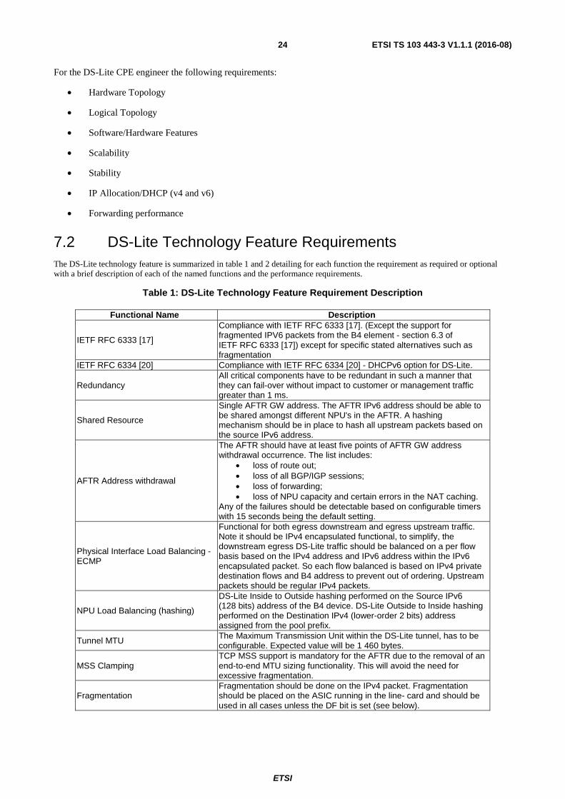
7.2 DS-Lite Technology Feature Requirements The DS-Lite technology feature is summarized in table 1 and 2 detailing for each function the requirement as required or optional with a brief description of each of the named functions and the performance requirements.
Compliance with IETF RFC 6333 [17]. (Except the support for fragmented IPV6 packets from the B4 element - section 6.3 of IETF RFC 6333 [17]) except for specific stated alternatives such as fragmentation
IETF RFC 6334 [20] Compliance with IETF RFC 6334 [20] - DHCPv6 option for DS-Lite.
Redundancy All critical components have to be redundant in such a manner that they can fail-over without impact to customer or management traffic greater than 1 ms.
Shared Resource
Single AFTR GW address. The AFTR IPv6 address should be able to be shared amongst different NPU's in the AFTR. A hashing mechanism should be in place to hash all upstream packets based on the source IPv6 address.
AFTR Address withdrawal
The AFTR should have at least five points of AFTR GW address withdrawal occurrence. The list includes:
• loss of route out; • loss of all BGP/IGP sessions; • loss of forwarding; • loss of NPU capacity and certain errors in the NAT caching.
Any of the failures should be detectable based on configurable timers with 15 seconds being the default setting.
Physical Interface Load Balancing - ECMP
Functional for both egress downstream and egress upstream traffic. Note it should be IPv4 encapsulated functional, to simplify, the downstream egress DS-Lite traffic should be balanced on a per flow basis based on the IPv4 address and IPv6 address within the IPv6 encapsulated packet. So each flow balanced is based on IPv4 private destination flows and B4 address to prevent out of ordering. Upstream packets should be regular IPv4 packets.
NPU Load Balancing (hashing)
DS-Lite Inside to Outside hashing performed on the Source IPv6 (128 bits) address of the B4 device. DS-Lite Outside to Inside hashing performed on the Destination IPv4 (lower-order 2 bits) address assigned from the pool prefix.
Tunnel MTU The Maximum Transmission Unit within the DS-Lite tunnel, has to be configurable. Expected value will be 1 460 bytes.
MSS Clamping TCP MSS support is mandatory for the AFTR due to the removal of an end-to-end MTU sizing functionality. This will avoid the need for excessive fragmentation.
Fragmentation Fragmentation should be done on the IPv4 packet. Fragmentation should be placed on the ASIC running in the line- card and should be used in all cases unless the DF bit is set (see below).
ETSI
ETSI TS 103 443-3 V1.1.1 (2016-08)25
Functional Name Description
IETF RFC 6333 [17] Fragmentation
Fragmentation should be done on the IPv6 packet, only as specified in IETF RFC 6333 [17] and if the DF bit is set, otherwise IPv4 fragmentation should be preferred. Used in conjunction with Stateful ICMP.
IANA well known address for IPv4-in-IPv6 tunnel
Use of IANA well known addresses for configuring IPv4-in-IPv6 tunnel. By default the AFTR will assume 192.0.0.1. Customer can configure other value if needed. This can be used for v4 ICMP messaging between B4 and AFTR.
NAT - Network Address and Port Mapping - Endpoint Independent Mapping
For two flows for a common inside source IPv4 address and port, the external address/port translation is independent of the destination IPv4 address and port and when the flows exist simultaneously in the NAT state table they will use the same translation.
A flow initiated externally can use the existing External/Inside IPv4 address/port mapping and it is independent of the source IPv4 address/port of the senders.
NAT - Paired IP Address Assignment
Translation to External IPv4 address is done in a paired fashion. A given Inside IPv4 B4 address is always translated to the same External IPv4 address.
NAT - Hair-pinning Different internal addresses on the same internal interface have to be able to reach each other using external address/port translations.
NAT - 1:1 IP Mapping Ability to configure a one to one type of mapping for particular inside-VRFs: every public IP will be mapped to one and only one private IP (multiple ports are allowed).
NAT - Outside-Service-App mapping for inside-VRF
Ability in the inside-vrf to provide the explicit outside serviceapp to be paired.
NAT - Port Limit configuration A maximum amount of ports can be configured for every IPv6 source B4 address.
NAT - Per-Protocol Timeout configuration
Timeout of mappings is critical and removing a NAT mapping at the appropriate time maximizes the shared port resource.
NAT - Dynamic Port Range start configuration
The start port for dynamic port ranges should be configurable to allow for a range of ports for static port mappings.
NAT - Software Load Balancing
NAT Inside to Outside hashing performed on the Source IPv6 B4 Address. NAT44 Outside to Inside hashing performed on the Destination IPv4 (lower-order 2 bits) address assigned from the pool prefix.
Shared Resource per Chassis Regardless of the number of NPUs
All DS-Lite resources should be shared under a single AFTR address, shared under multiple AFTR addresses on the same virtual interface, a single shared IPv4 public range per chassis or instance, shared NAT groups on a single AFTR address, shared NPUs, shared routing resources, memory, shared PCP cache and assignments across multiple NAT groups or a single NAT group.
Port Allocation
In order to reduce the volume of data generated by the NAT device (logging creation and deletion of data), bulk port allocation can be enabled. When bulk port allocation is enabled and when a subscriber creates the first session, a number of contiguous outside ports are pre-allocated. A bulk allocation message is logged indicating this allocation.
Deterministic NAT Algorithmically maps a customer's IPv6 B4 address to a set of public IPv4 address/ports statically, allowing a significant reduction in logging.
Dynamic Port Assignment Oversubscription (based on threshold)
Creation of a percentage out of the 60k block allocation per IPv4 public address. For example the first 100 ports is a primary assignment for each and every B4 within a single IP through DeNAT. The B4 then can get as many, max 3 000, ports as needed over-subscribing until a 80 % (configurable) port assignment is reached per IP, and then a restriction is placed with no B4 being able to request any more ports over the 500 ports mark. Sessions however are not dropped. Once the utilization drops to 70 % once again (configurable) the B4s are free then to oversubscribe once again.
Source Filtering per AFTR Address into Separate NAT Groups
NAT grouping should be configurable and able to delineate by IPv6 source prefix. So a single AFTR address (anycast) with the group rules and characteristics for multiple groups based on source IPv6 prefix. This allows separation of B2B, B2C, platform and services separation without using a different AFTR address.
Port Reservation To prevent dynamic or static allocation (within deterministic NAT) of the first 5 000 port blocks, for assignment of well known ports within static routing.
ETSI
ETSI TS 103 443-3 V1.1.1 (2016-08)26
Functional Name Description
PCP General Implementation Both PCP IETF RFC drafts version 12 [40], 13 [41] and 29 [42] should be supported and configurable.
PCP Static Support for PCP to allocate static port bindings.
PCP Dynamic Support for PCP to allocate dynamically assigned port and IP bindings.
PCP IP and Port Reservation for encrypted/fixed headers
To allow configuration of IPs and ports to PCP's allocation assignment for both static (portal based customer configured static port forwarding) and PCP UPnP and PMP dynamically assigned port and IP ranges for specific applications that are encrypted or have fixed headers.
Allows multiple sessions from multiple PCs behind a single B4 to access the same port by assigning a separate IP to the B4 (IPv4 public). The ability to dynamically allocate a static port forward for a different outside IP as the subscriber got assigned when the particular port is in use. Reasoning is bittorrent clients with UPnP and PCP to the AFTR will not be able to negotiate the same port for multiple sessions from different PCs, behind the same B4, and given all clients use the same "fixed" port by default it is better to allocate a different outside IP.
PCP Failure Application of PCP failover or failure response to prevent unnoticed PCP failure.
FTP ALG (Active and Passive) FTP clients are supported with inside (private) address and servers with outside (public) addresses. Passive FTP is provided by the basic NAT function. Active FTP is used with the ALG.
RTSP ALG (ALP)
Remote control protocol for streamers (which use RTP/RTCP or RDT). Our implementation considers the server is located "outside" and clients are "inside". RTSP is used in many streamers like QuickTime or RealNetworks. Both "SETUP" and "SETUP response" are analysed. Based on this information, the translation entry will be created in the table.
SIP ALG (ALP) SIP requires control and signalling on separate port to the data traffic and therefore requires an ALG to function.
PPTP ALG PPTP, used in many VPN setups, requires control and signalling on separate port to the data traffic and therefore requires an ALG to function.
TFTP ALG TFTP requires control and signalling on separate port to the data traffic and therefore requires an ALG to function.
Use of Application SVI's, connecting multiple routing entities (inside/private VRF, outside/public VRF)
NAT should be possible from any routing context (VRF, GRT) to any routing context (VRF, GRT).
Stateful ICMP
Stateful ICMP mappings between inside and outside ICMP identifiers should be supported with 3 retries on any specific destination host upstream and downstream (based on fragmented packets received on upstream from the CPE in case the CPE itself does not support stateful ICMP) This is to prevent flooding of ICMP messages.
Thresholds
Configurable thresholds using watermarks should be supported to monitor the resources on the AFTR:
• Port percentage per IP • IP Address percentage per range assigned and per NAT
group • Resource per NPU • Memory utilization • Processor utilization per NPU • PCP Percentage IP assignments • Clustering utilization (the total utilization if one of the pair of
the cluster goes down) • Interface utilization BW • Number of active flows • DS-Lite sessions (dynamic thresholds) • SI-ID (extension) numbers per NPU and chassis (based on
both private IPv4 and public IPv4 used out of the range assigned).
ETSI
ETSI TS 103 443-3 V1.1.1 (2016-08)27
Functional Name Description
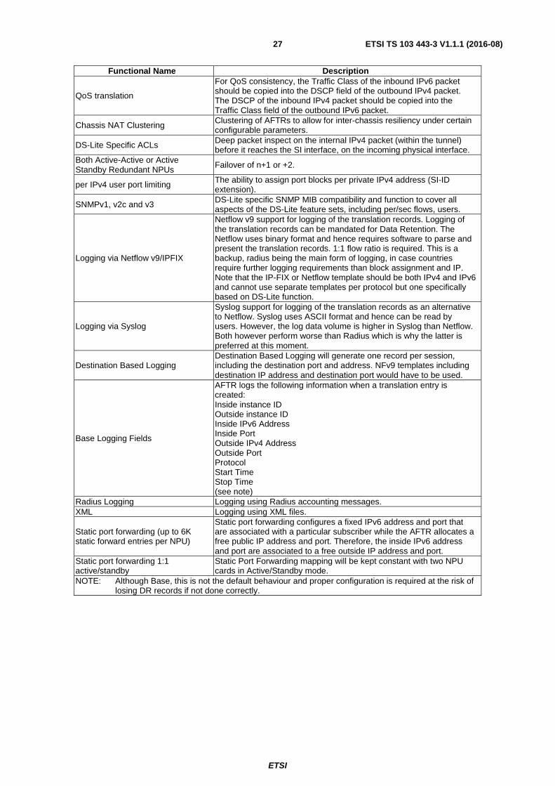
QoS translation
For QoS consistency, the Traffic Class of the inbound IPv6 packet should be copied into the DSCP field of the outbound IPv4 packet. The DSCP of the inbound IPv4 packet should be copied into the Traffic Class field of the outbound IPv6 packet.
Chassis NAT Clustering Clustering of AFTRs to allow for inter-chassis resiliency under certain configurable parameters.
DS-Lite Specific ACLs Deep packet inspect on the internal IPv4 packet (within the tunnel) before it reaches the SI interface, on the incoming physical interface.
Both Active-Active or Active Standby Redundant NPUs Failover of n+1 or +2.
per IPv4 user port limiting The ability to assign port blocks per private IPv4 address (SI-ID extension).
SNMPv1, v2c and v3 DS-Lite specific SNMP MIB compatibility and function to cover all aspects of the DS-Lite feature sets, including per/sec flows, users.
Logging via Netflow v9/IPFIX
Netflow v9 support for logging of the translation records. Logging of the translation records can be mandated for Data Retention. The Netflow uses binary format and hence requires software to parse and present the translation records. 1:1 flow ratio is required. This is a backup, radius being the main form of logging, in case countries require further logging requirements than block assignment and IP. Note that the IP-FIX or Netflow template should be both IPv4 and IPv6 and cannot use separate templates per protocol but one specifically based on DS-Lite function.
Logging via Syslog
Syslog support for logging of the translation records as an alternative to Netflow. Syslog uses ASCII format and hence can be read by users. However, the log data volume is higher in Syslog than Netflow. Both however perform worse than Radius which is why the latter is preferred at this moment.
Destination Based Logging Destination Based Logging will generate one record per session, including the destination port and address. NFv9 templates including destination IP address and destination port would have to be used.
Base Logging Fields
AFTR logs the following information when a translation entry is created: Inside instance ID Outside instance ID Inside IPv6 Address Inside Port Outside IPv4 Address Outside Port Protocol Start Time Stop Time (see note)
Radius Logging Logging using Radius accounting messages. XML Logging using XML files.
Static port forwarding (up to 6K static forward entries per NPU)
Static port forwarding configures a fixed IPv6 address and port that are associated with a particular subscriber while the AFTR allocates a free public IP address and port. Therefore, the inside IPv6 address and port are associated to a free outside IP address and port.
Static port forwarding 1:1 active/standby
Static Port Forwarding mapping will be kept constant with two NPU cards in Active/Standby mode.
NOTE: Although Base, this is not the default behaviour and proper configuration is required at the risk of losing DR records if not done correctly.
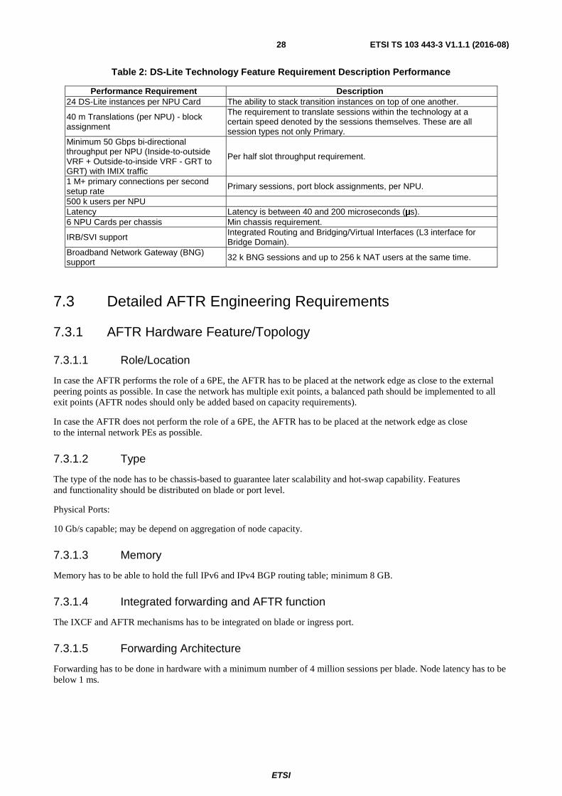
Performance Requirement Description 24 DS-Lite instances per NPU Card The ability to stack transition instances on top of one another.
40 m Translations (per NPU) - block assignment
The requirement to translate sessions within the technology at a certain speed denoted by the sessions themselves. These are all session types not only Primary.
Minimum 50 Gbps bi-directional throughput per NPU (Inside-to-outside VRF + Outside-to-inside VRF - GRT to GRT) with IMIX traffic
Per half slot throughput requirement.
1 M+ primary connections per second setup rate
Primary sessions, port block assignments, per NPU.
500 k users per NPU Latency Latency is between 40 and 200 microseconds (μs). 6 NPU Cards per chassis Min chassis requirement.
IRB/SVI support Integrated Routing and Bridging/Virtual Interfaces (L3 interface for Bridge Domain).
Broadband Network Gateway (BNG) support 32 k BNG sessions and up to 256 k NAT users at the same time.
7.3 Detailed AFTR Engineering Requirements
7.3.1 AFTR Hardware Feature/Topology
7.3.1.1 Role/Location
In case the AFTR performs the role of a 6PE, the AFTR has to be placed at the network edge as close to the external peering points as possible. In case the network has multiple exit points, a balanced path should be implemented to all exit points (AFTR nodes should only be added based on capacity requirements).
In case the AFTR does not perform the role of a 6PE, the AFTR has to be placed at the network edge as close to the internal network PEs as possible.
7.3.1.2 Type
The type of the node has to be chassis-based to guarantee later scalability and hot-swap capability. Features and functionality should be distributed on blade or port level.
Physical Ports:
10 Gb/s capable; may be depend on aggregation of node capacity.
7.3.1.3 Memory
Memory has to be able to hold the full IPv6 and IPv4 BGP routing table; minimum 8 GB.
7.3.1.4 Integrated forwarding and AFTR function
The IXCF and AFTR mechanisms has to be integrated on blade or ingress port.
7.3.1.5 Forwarding Architecture
Forwarding has to be done in hardware with a minimum number of 4 million sessions per blade. Node latency has to be below 1 ms.
ETSI
ETSI TS 103 443-3 V1.1.1 (2016-08)29
7.3.2 AFTR DS-Lite specific engineering requirements
7.3.2.1 Tunnel Identifiers/Client-Customer ID
For data retention purposes, tunnel identifiers has to be uniquely associated with a single CPE.
7.3.2.2 MTU Sizing/TCP MSS
TCP MSS support is mandatory for the AFTR.
7.3.2.3 Load balancing
Load balancing across aggregated interfaces has to be supported. This includes IP and port allocation ECMP, PVST LB, LDP hashing, etc.
7.3.2.4 IPv4 Private Subnet Segmentation
The AFTR has to be able to segment the IP blocks into smaller blocks for the local interfaces.
7.3.2.5 Non-ALG Deployment
The AFTR has to have a non-ALG approach for decapsulation.
7.3.2.6 Traffic Prioritization
Traffic prioritization has to be possible to e.g. support B2B customers running video or voice to the translation interface.
7.3.2.7 Data retention (DR)
For DR purposes two potential methodologies exist, NAT Caching with filters or Netflow. The requirement is to hold, for each flow, the following entries:
• Source IPv4 address
• Source IPv6 address
• Source port (internal IPv4)
• Remote destination port (external IPv4)
• Time stamp
• Remote IPv4 address
• Remote IPv6 address (this will be the AFTR address) (optional)
• Incoming Interface (optional)
• Outgoing interface (optional)
• Client-ID (if different from the IPv6 address)
7.3.2.8 UPnP/Port forwarding/PCP
The AFTR has to allow uPnP forwarding and port mapping through the tunnel.
ETSI
ETSI TS 103 443-3 V1.1.1 (2016-08)30
7.3.3 AFTR General software engineering requirements
7.3.3.1 Topology dependency
The AFTR general software engineering requirements depend on the deployment topology. In general two topologies are possible, one where the AFTR functions as a full MPLS 6PE router, the "integrated topology" and one where the AFTR functions as a L3 router, hairpinning connections through an external 6PE router, the "hairpin topology".
List of features required for both IPv4 and IPv6/L2 and L3 for an integrated topology solution:
• MP BGP (as well 6PE and 6VPE)
• BGP Community/32 bit AS
• MPLS LDP (potentially only v4 native but the requirement for v6 native MPLS may become an absolute)
• ECMP
• QoS (v4/v6) - classification, priority queuing, etc.
• QPPB/SCU/DCU
• SNMP (transport over v4 and v6) v1/v2/v3
• ACLs/Prefix Listing (both v4/v6)
• TACACS/RADIUS (v4/v6)
• Syslog (event reporting for v4 and v6 as well as transporting over both protocols)
• CoPP (v4/v6)
• Netflowv9 (potentially previous versions will be required depending on the state of the network architecture implementation of Netflow)
• XML (v4 and v6 reporting and transport)
• Mac Accounting
• 802.1q
• Ether-channel
• Ether OAM
• NSF/GR (v4/v6)
• Policy Based Routing (v4/v6)
• ISIS (Potentially MT for ISIS as well if the MPLS IPv6 LDP allows for dual stacking) (v4/v6)
• Static Routing (v4/v6)
• OSPFv2/v3
• CDP/LLDP (v4/v6)
• VRRP/HSRP (v4/v6)
• VLAN Mapping/Double Tagging
• L3 Multicasting/MFIB (v4/v6)
ETSI
ETSI TS 103 443-3 V1.1.1 (2016-08)31
• IPv6 Forwarding
• IPv4 Forwarding
• Ethernet technologies
• Hardware forwarding functionality, instead of software, across all priority flows (v4/v6)
• Virtual Interfaces (v4/v6)
• AAA (v4/v6)
• BFD (v4/v6)
• MLD/L2 Multicast
• Full NDP (ICMPv6, DAD, NUD, etc.)
• PIM/IGMPv2/v3
• CEF/dCEF
• Anycast
• Route Reflection (v4/v6)
• Standard v4 VPN
• ISSU/SSO
• NTP (v4/v6)
• SEND
• IPSec
• DNS (v4/v6 server and client)
• DHCP relay (v4/v6)
• MSTP/RSTP
• L2/L3 Load Balancing (v4/v6)
• VPLS (v4/v6)
• L2 Bridging
• NAT64
• DS-Lite
• NAT Cache Writing
• SSH/Telnet (v4/v6)
• Authentication across most protocols such as SNMPv3/BGP
• PS-BGP
7.3.3.3 Hairpin topology engineering requirements
List of features required for both IPv4 and IPv6/L2 and L3 for a "hairpin topology" solution:
• SNMP (transport over v4 and v6) v1/v2/v3
ETSI
ETSI TS 103 443-3 V1.1.1 (2016-08)32
• ACLs/Prefix Listing (both v4/v6)
• TACACS/RADIUS (v4/v6)
• Syslog (event reporting for v4 and v6 as well as transporting over both protocols)
• CoPP (v4/v6)
• Netflowv9 (potentially previous versions will be required depending on the state of the network architecture implementation of Netflow)
• XML (v4 and v6 reporting and transport)
• 802.1q
• Ether-channel
• Ether OAM
• Static Routing (v4/v6)
• CDP/LLDP (v4/v6)
• VRRP/HSRP (v4/v6)
• IPv6 Forwarding
• IPv4 Forwarding
• Ethernet technologies
• Hardware forwarding functionality, instead of software, across all priority flows (v4/v6)
• Virtual Interfaces (v4/v6)
• Full NDP (ICMPv6, DAD, NUD, etc.)
• CEF/dCEF
• Anycast
• ISSU
• NTP (v4/v6)
• SEND
• BFD
• IPSec
• DNS (v4/v6 server and client)
• MSTP/RSTP
• L2/L3 Load Balancing (v4/v6)
• NAT64
• DS-Lite
• NAT Cache Writing
• SSH/Telnet (v4/v6)
• Authentication across most protocols such as SNMPv3/BGP
ETSI
ETSI TS 103 443-3 V1.1.1 (2016-08)33
• PS-BGP
• ECMP
7.3.4 Scalability
The AFTR has to be engineered to be able to hold a minimum of 20 million sessions at one time. The AFTR has to be engineered to support future increase of throughput per blade, e.g. by having processing done through a feature card.
7.3.5 AFTR Performance
7.3.5.1 General considerations
The AFTR performance is based on lowest acceptable benchmarks and the actual delivery of throughput, convergence, failover and latency for all aspects and features within the chassis interoperable on the network.
All performance requirements are to be operated based on peak capacity and average throughput. Both are to be considered for the platform placement in capacity. Capacity is also to be operated on the basis of expected growth of subscribers and increase of throughput per subscriber.
7.3.5.2 Throughput interfaces
All interfaces have to be engineered to be 10 Gb/s and work at line rate. The interface has to be operated so that it is compatible with the local cable P/PE router connectivity.
7.3.5.3 Node latency
The required node latency has to be engineered to be 100 microseconds.
7.3.5.4 Flow throughput
The flow throughput shall be established as defined by three main performance figures:
• CPE initialization: This is the initialization of the port allocation per subscriber (i.e. when a CPE comes up for the first time) with a single external IP per CPE.
• Primary flow initialization: Primary flow initialization is if the CPE has already been granted a port allocation but the flow is a "new" flow in the NAT cache, which further defined would be a flow that has no entry except a source IPv6 address already in the cache, so the whole flow needs to be allocated and set into the NAT cache. This shall be engineered for 800 k flows per 40 Gb/s chassis throughput capacity.
• Secondary flow initialization: This shall be engineered and operated to have 1 million flows per 40 Gb/s chassis throughput capacity.
7.3.5.5 Convergence
Convergence of routing and link failure shall be engineered to be well within 10 ms.
7.3.6 AFTR Application proxy
Table 3 shows the DS-Lite "proxy" requirements. As the actual DS-Lite flow is based on a 4-4 NAT encapsulated in an IPv6 tunnel, there is no true ALG translation. However the AFTR requires knowledge of protocol requirements and therefore "proxy" functionality (as with standard NAT44).
Table 3 lists the protocols that currently should be engineered so they are supported natively or need to be engineered with PCP (port forwarding) to function.
202 Google Talk® Data 5 3 180 Google Talk® Voice 4 3 92 IRC 1 92 IRC file transfer (server) 2
440 Skype® Phone to PC 16 441 Skype® PC to PC AV Chat 10 10 248 Skype® Generic 6 2 21 Skype® PC to PC 17 9 44 PC: Valve's Steam Service 17 5 90 PC: World Of Warcraft®
109 PC: Counter-Strike® 23 3
ETSI
ETSI TS 103 443-3 V1.1.1 (2016-08)35
Seq# Application/protocol Max Port binding
Avg Port binding
25 Windows® Update 4 2 Windows® Activation 3 3
49 Avg Update 2 1 123 RDP 297 Nintendo® Wii® Web Browsing 4 2 324 Nintendo® Wii® Control 5 1 78 Nintendo® Wii® Data 5 1 PSP 39 16
NOTE : These are examples of relevant products and services available commercially. This information is given for the convenience of users of the present document and does not constitute an endorsement by ETSI of these products and services.
8 General Considerations
8.1 Hardware Considerations A carrier grade NAT solution is to be engineered with a max capacity of 120 gigabytes, 130 000 IP SI-ed connections and 4 million flows allowing for 32 flows per customer at max capacity. The customer end point, based on max flows per IPv4 private address, will need to be limited to allow for max 2 000 flows per client restricting and not limited on tunnels per address.
The AFTR shall be engineered as a carrier grade router allowing for all requirements within the determined PE requirements.
The AFTR, shall be engineered to allow for RP redundancy, have 4 to10 open blade slots allowing for a single ISA and a port based NPU placed within it. Each port card/module shall be engineered to hold a 10-gigabyte interface, which needs to be matched at the PE router. There will need to be two 10-gigabytes connections into the AFTR one primary ingress and one primary egress. The primary egress will need to be engineered to hold the public IPv4 interface, but will need to be dual stacked for redundancy in case the primary ingress, holding the IPv6 interface was to fail and visa versa on the primary ingress. Considering the priority of this traffic two AFTRs, in HA mode shall be engineered to allow for a client to access either AFTR in a cable operator's country network. This gives chassis redundancy, so the design attempts to allow for growth as the DS-Lite requirement increases in capacity and customer base, by holding two chasses with a single RP, one blade holding a 20 gigabytes NPU and a port card, so that it is hardly loaded, within any given region of the cable operators network. This is to support a maximum of 40 gigabytes capacity with failover of 20 gigabytes. Considering cost, as the chassis accounts for only 3 % of the actual overall cost, this allows redundancy comparative to a single chassis holding two NPUs and ISAs.
8.2 DS-Lite Scalability The details of the scalability are structured below showing the engineering requirements for delivery in any single local cable network scenario.
The scalability requirements to be engineered are:
1) Min of 4-6 million flows per NPU.
2) 132 k customer IP sources per NPU.
3) 20-gigabytes throughput, 10 gigabytes in, 10 gigabytes out.
4) Load balancing on ingress ports across the chassis.
5) Two AFTRs per cable operators network.
6) Two global AFTRs for failover of traffic.
7) 500 k secondary bindings per second NPU.
ETSI
ETSI TS 103 443-3 V1.1.1 (2016-08)36
8) 500 k initial bindings per second per NPU.
9) Scalability configurable for ports per IP and sessions per IP.
10) Min of 120-gig throughput per chassis.
11) Min of 4 slots, max 10 port slots allowing for 120 gig backplane.
12) Matching blades using both a NAT NPU and a port card in a single blade.
The ability to do 20 gigabytes per chassis, 40 gigabytes total per local or regional network shall be engineered, until the need arises to increase that base traffic, using monitoring abilities to validate the capacity on the node.
8.3 PCP Considerations The present document specifies the engineering and operational requirements for DS-Lite as an IPv6 transition technology such that it is implementable across the cable network domains to provide a seamless experience to users accessing IPv4 network services through new IPv6 only networks and that enables current and new content to be delivered seamlessly to IPv6 users by deploying DS-Lite. DS-Lite in its base form however only considers connectivity being initiated from the B4 LAN-side and the end user is not assumed to deploy any services that require connectivity to be established and initiated from the WAN-side. For this purpose PCP was developed and should be engineered if the functionality is required.
8.4 NDP Considerations As there is no direct IPv6 connectivity, 6PE configuration will be used. The NDP timer configuration should not be touched; however these are the defaults for the design in case the hair-pinned topology is used:
• min-advertisement-interval 200
• max-advertisement-interval 600
• router-lifetime 1 800
• no reachable-time
• no retransmit-time
• current-hop-limit 64
• no managed-configuration
• no other-stateful-configuration
• no use-virtual-mac
9 Support Systems
9.1 Testing The conformance tests shall be carried out to validate the implementation of DS-Lite in accordance with ETSI TS 101 569-1 [1].
Each of the validation tests listed in table 4 should be performed in the environments with the laboratory topologies, network integration and standalone.
ETSI
ETSI TS 103 443-3 V1.1.1 (2016-08)37
Table 4: Validation Tests
TEST DESCRIPTION PLATFORMS RESULT Validation Testing
v4 Config Verification IPv4 connectivity and NA4 compliance
Image compatibility testing Image validation against the present IPv6 configuration
IPv6 Basic Feature Regression such as NDP, etc.
Validation of the basic features within IPv6
IPv6 Addressing Validation
Validate all addressing structures and multiple interfaces can be configured within the DS-LITE address structure
Static Routes
ISIS Validation that ISIS works correctly egress and ingress on the AFTR for IPv4 to IPv6 and the reverse
TCP MSS end-to-end/MTU
IPv6 MP BGP validation Validation of the present IPv6 network architecture MP BGP implementation
IPv6 over MPLS 6PE Configuration validation within the AFTR configuration
IPv6 over MPLS 6VPE Configuration validation within the AFTR configuration
IPv6 ACLs/Route Maps Ingress/egress IPv6 ACLs and the same on IPv4
DHCPv4 lease assignment
DHCPv6 will be used for the lease assignment but it is a requirement to test if the DS-LITE CPE device can give out leases to the clients
DNS Testing the integrated DNS
Transit and Directly Connected throughput
There are two implementations of physical path. 1 is the transit traffic through the AFTR processor but not physically connected and the second is directly connected interfaces on the AFTR card itself. Both have to get configuration validation. (This is not a load test)
NAT process Testing the numerous NAT processes bi-directionally
Application transit
Validating each of the following DNS and IP based applications:
Filezilla® • Bittorrent™ download • YouTube® video playing • Azureus® download • Skype®
Specific logging Testing the specific logging for translation packets
Monitoring and Management
Testing the SNMP configuration for both v1 and v3, that syslog covers the events within the translation functionality
ETSI
ETSI TS 103 443-3 V1.1.1 (2016-08)38
TEST DESCRIPTION PLATFORMS RESULT Netflow v9
Security Access
Validate the network IPv6 ACL implementation leaves no gaps within preventing access on the equipment
Last resort Validation of last resort. This is particular to the DNS solution being developed
Convergence times How quickly certain protocols/sessions will recover if sessions/adjacencies drop
HA recovery This will include all redundant physical paths, routing and physical card and link redundancy
Copp Interoperability Validate the present Copp design does not conflict with the new DS-LITE topology and process
Performance Testing
IPv4 baseline load test Primary load testing for baseline executed with no translation solely on IPv4
IPv6 load baseline test Primary load testing for baseline executed with no translation solely on IPv6
IPv6/IPv4 dual stack load baseline test
Dual stack baseline testing with pathological, variable and fixed traffic using all well-known ports, or as many as possible
IPv6/IPv4 bi-directional tunnelling throughput/error rate and node translation latency verification
To validate the bi-directional throughput of the IPv6 to IPv4 traffic on pathological, variable and fixed traffic using all well-known ports, or as many as possible
Session and route convergence on route failure
Session and route convergence on interface or link failure
IPv6 to IPv4 simultaneous session establishment through DUT/AFTR
Translation specific test to establish the max number of sessions per sec/per sec the device can establish
NOTE : These are examples of relevant products and services available commercially. This information is given for the convenience of users of the present document and does not constitute an endorsement by ETSI of these products and services.
10 CPE Specifications for IPv6
10.1 Summary
10.1.1 Reference Architecture
The reference architecture is given in the figure 7.
The functional description and for further details refer also to IETF RFC 6333 [17], however where there may be differences with the requirements in IETF RFC 6333 [17] and the present document then the requirements of the present document take precedence.
ETSI
ETSI TS 103 443-3 V1.1.1 (2016-08)39
Figure 7: Reference Architecture
10.1.2 CPE Requirements
10.1.2.1 General
The CPE shall support the following RFC's:
• IETF RFC 2460 [21], Internet Protocol v6 (IPv6) Specification.
• IETF RFC 4861 [22], Neighbor Discovery for IPv6.
The DOCSIS 2.0 + IPv6 cable modem shall support the following:
• DOCSIS 2.0+IPv6 Cable Modem Specification [24].
• IPv6 management as defined in the OSSIv3.0 Specification [25].
• Provisioning Mode Override, as defined in [24] and [25].
10.1.2.2.2 DOCSIS 3.0 Cable Modem
The DOCSIS 3.0 cable modem shall support the following:
• MAC and Upper Layer Protocols Interface Specification (MULPI) [26].
• Upstream Drop Classifiers.
IPv6 networkHFC
AFTR/CGN/LSN
IPv6 network
IPv4 network
CM
IPv4 Pc
IPv6 PcB4/
DS-Lite CPE/Home Gateway
IPv4/IPv6 Pc
B4 / DS-Lite CPE / Home Gateway – ‘Basic Bridging BroadBand’-device @ the client site.- Dual-stack IPv4/IPv6 (IPv4 private and IPv6 public/global addresses).- ‘Normal’ IPv6 traffic forwarding and IPv4 traffic encapsulation over an IPv4-in-IPv6 Tunnel.- Receives LSN/AFTR tunnel-endpoint through DHCPv6 (option not standardized yet).- Initiates the softwire which terminates at the AFTR.
AFTR / CGN / LSN – Address Family Translation Router as a network element in the ISPs network.- Terminates IPv4-in-IPv6 Tunnels.- Does the (private to public and v.v.) NAT44 translations.- Maps IPv6 src-address, IPv4 src-address & IPv4 src-port to uniquely identify customers
IPv6 traffic
IPv4 traffic encapsulated in IPv6 tunnel IPv4 traffic
IPv6 WAN interface
DHCPv4
DHCPv4
- CPE initiates softwire to AFTR once an IPv4 packet comes from the LAN and is destined to a public IPv4 destination.- CPE encapsulates IPv4 packet into an IPv6 packet and sends across the tunnel.- LSN decapsulates IPv6 packet, then does NAT44 from a private IPv4 to a public IPv4 address (each new session logged, 9 fields, for DR) and creates table-entry for uniquely mapped source IPv6 address (tunnel endpoint) & source IPv4 address & tcp/udp-port.
- Public IPv4 src-address/port triggers lookup in LSN to identify customer’s IPv6 address (tunnel endpoint) and original private IPv4 address/port.- IPv4 destination gets rewritten into original IPv4 private source, packet gets encapsulated into IPv6 and is sent across the tunnel.- CPE decapsulates packet and forwards IPv4 packet to original source/port.
ETSI
ETSI TS 103 443-3 V1.1.1 (2016-08)40
• OSSIv3.0 Specification [25].
• Provisioning Mode Override, as defined in [25].
10.1.2.3 eRouter/Home Gateway
The following engineering requirements for the eRouter/Home gateway shall be supported:
• IPv6 provisioning of CPE devices as specified in [27].
• IPv6 address assignment, as specified in [27].
• IETF RFC 4361 [28] to make the DHCPv4 client identifier identical to the DHCPv6 DUID.
• Support BBF TR-069 [29] via native IPv6 transport to allow remote management of WiFi and router parameters.
10.1.2.4 LAN-side Interface
The following requirements are to be supported as given below:
• has to support SLAAC;
• should support IETF RFC 6106 [39] DNS resolver information;
• should support stateless DHCPv6 (INFORM) server on LAN side;
• may support stateful DHCPv6 server (IA_NA) on LAN side; this may be needed to identify a single customer in a delegated prefix (e.g. IP lawful intercept in multi-dwelling business park served by a single router);
• shall enable SLAAC (with IETF RFC 6106 [39] and stateless DHCPv6 mode by default);
• may provide option to switch from SLAAC to stateful DHCPv6;
• shall support forwarding and filtering with:
- IPv4 NAT/NAPT;
- IPv4 Static NAT;
- IPv4 Inbound port forwarding;
- IPv4 stateful packet firewall (5-tuple filters), enabled by default;
- IPv6 stateful packet firewall (5-tuple filters), enabled by default;
• shall support Dual-Stack Lite;
• should support the Recursive DNS Server Option.
10.1.2.5 Software Features
10.1.2.5.1 Static Configuration
The router has be able to hold a static configuration. The configuration control has to be split between customer and network cable operator.
10.1.2.5.2 Tunnel Bindings
The tunnel bindings should have a lifetime around 5 to 10 minutes. To avoid double assignment of active bindings in case of delegated prefix change, prefixes have to be quarantined for longer than the binding lifetime.
ETSI
ETSI TS 103 443-3 V1.1.1 (2016-08)41
10.1.2.5.3 P2P
The Cable Gateway CPE has to be able to initiate and hold point-to-point DS-Lite tunnels.
10.1.2.5.4 Gi-DS-Lite
The Cable Gateway CPE has to be able to setup and use a non-directly connected IPv6 tunnel to external AFTRs.
10.1.2.5.5 Tunnel Identifiers/Client-Customer ID (flow label identifier)
To avoid problems with depletion of IPv4 private address space per AFTR, the Cable Gateway CPE has to be able to identify by not solely using the IPv4 address as Client ID. The CPE should use either the flow label or the IPv6 address; both methodologies should be supported.
10.1.2.5.6 MTU Sizing/TCP MSS
TCP MSS is not required; MTU size and MSS clamping functionality has to be supported.
10.1.2.5.7 Non-ALG Deployment
The DS-Lite encapsulation methodology should solely encapsulate the IPv4 packet within the IPv6 with no modification of the packet itself; no ALGs should be used.
10.1.2.5.8 DNS over IPv6
DNS has to be able to be transported over both IPv4 and IPv6.
10.1.2.5.9 Port Forwarding
Port forwarding should be possible before encapsulation of the IPv4 packet and therefore logil reside on the dual stack internal LAN interface. Future support for uPnP and PCP is required.
10.1.2.5.10 SI
Softwire initiation has to be engineered so that it is guarantying end to end last resort for traffic needed to be tunnel. The mechanisms differ from vendor to vendor, but it should be based on the internal interface and configurable due to the potential of IPv4 management, especially with the integrated solution as management over IPV6 is not yet fully defined yet for modem provisioning. See the draft-ietf-softwire-dual-stack-lite-05 [i.3] and draft-ietf-softwire-gateway-init-ds-lite [i.4].
10.1.2.5.11 DHCPv4 Internal
DHCPv4 internal to the customer LAN has to be driven from the CPE and be private addressing either 10.x or 192.168.x originations.
10.1.2.5.12 DHCPv6 - PD Internal and external
DHCPv6 for the external interface has to be generated so DHCPv6-PD has to be featured in the CPE. This has to able to distribute an EUI-64 allocation. This should be extended following industry adoption of EUI-112 RFCs.
The adopted use of DHCPv6 specifications, IETF RFC 3646 [30] would be preferable to allocate stateful node addresses without the need for EUI-64, or allow the HDCP relay to the CNR to assign host addresses within the same internal subnet as the internal interface.
The gateway has to be configurable through DHCPv6 [30] or through RA distribution from the CMTS, either method should be featured.
ETSI
ETSI TS 103 443-3 V1.1.1 (2016-08)42
10.1.2.5.13 Non-ALG Deployment
The DS-Lite encapsulation methodology should not have any ALG necessity or functionality, solely the encapsulation of the IPv4 packet within the IPv6 with NO modification of the packet itself.
10.1.2.5.14 Customer Management (Access and Reporting)
Customer management has to be limited to port forwarding potential on the ingress interface customer facing. HTTP access for management and a close system preventing any changes to the "static" IP configuration for the cable operator's corporate control. Web-UI is the only method allowed.
10.1.2.5.15 Cable Operators Corporate Management (IPv6 or IPv4)
Management should be in-band and out-of-band (depending on the out-of-band technical feature set) on the IPv4 or IPv6. However it is most likely that if non-integrated, the management of the CPE routers will be over IPv6, to avoid having to further increase the path and having to add another private address scheme which could be problematic.
10.1.2.5.16 Port Forwarding
Port forwarding should be capable before the encapsulation of the IPv6 packet and therefore should sit on the dual stack internal interface internally facing the customer LAN. NAT_PMP functionality as part of or a further deployment of port forwarding should be a considered feature.
10.1.2.5.17 UPnP
UPnP functionality has to be engineered.
10.1.2.5.18 Firewall
The CPE cable router should have an integrated firewall with full Rulebase functionality for both the cable operator's corporate and customer management. Corporate encoding should be hardcoded for the most part and customer soft coded.
10.1.2.5.19 Standard Hardware and Software Features for the CPE
• 4 x Network - Ethernet 10Base-T/1000Base-TX - RJ-45.
• 1 x Network - Ethernet 10Base-T/1000Base-TX - RJ-45 (WAN).
• USB Port.
Encryption Algorithms
• WPA2.
• WPA-PSK.
• WPA.
• 128-bit WEP.
• 64-bit WEP.
10.1.2.6 Performance
10.1.2.6.1 Forwarding
CPE tunnel forwarding performance has to not be lower than 75 % of total connected downstream bandwidth and 40 % of total connected upstream bandwidth.
10.1.2.6.2 Node latency
Node latency has to be under 2 ms.
10.1.2.6.3 Max sessions
The CPE router has to be able to hold 10 000 sessions minimum.
10.1.2.7 DS-Lite
10.1.2.7.1 General
Dual-Stack Lite IETF RFC 6333 [17] enables both continued support for IPv4 services and incentives for the deployment of IPv6. It also de-couples IPv6 deployment in the service provider network from the rest of the Internet, making incremental deployment easier. Dual-Stack Lite enables a broadband service provider to share IPv4 addresses among customers by combining two well-known technologies.
DS-Lite traffic is forwarded over the CE router's native IPv6 WAN interface, and not encapsulated in another tunnel.
The IPv6 CE router should implement DS-Lite functionality. If DS-Lite is supported, it has to be implemented according to IETF RFC 6333 [17]. The present document takes no position on simultaneous operation of Dual-Stack Lite and native IPv4.
10.1.2.7.2 WAN requirements:
The CE router has to support configuration of DS-Lite via the DS-Lite DHCPv6 option IETF RFC 6334 [20]. The IPv6 CE router may use other mechanisms to configure DS-Lite parameters. Such other mechanisms are not specified within the present document.
The IPv6 CE router has to be engineered so that it does not perform IPv4 Network Address Translation (NAT) on IPv4 traffic encapsulated using DS-Lite.
If the IPv6 CE router is configured with an IPv4 address on its WAN interface, then the IPv6 CE router should disable the DS-Lite Basic Bridging BroadBand (B4) element.
ETSI
ETSI TS 103 443-3 V1.1.1 (2016-08)44
10.1.2.7.3 Security Considerations
It is best practice to filter malicious traffic (e.g. spoofed packets, "Martian" addresses, etc.). Thus, the IPv6 CE router should support basic stateless egress and ingress filters. The Cabe router is also expected to offer mechanisms to filter traffic entering the customer network; however, the method by which vendors implement configurable packet filtering is beyond the scope of the present document.
10.1.2.7.4 Security requirements:
The IPv6 CE router should support IETF RFC 6092 [31]. In particular, the IPv6 CE router should support functionality sufficient for implementing the set of recommendations in IETF RFC 6092 [31], section 4. Such functionality could be enabled by default or mechanisms by which users would configure it.
The IPv6 CE router should support ingress filtering in accordance with BCP 38 IETF RFC 2872 [32].
NOTE: This requirement has been downgraded from a required feature from IETF RFC 6204 [33] due to the difficulty of implementation in the CE router and the feature's redundancy with upstream router ingress filtering.
If the IPv6 CE router firewall is configured to filter incoming tunneled data, the firewall should provide the capability to filter decapsulated packets from a tunnel.
10.2 DHCP
10.2.1 DHCPv6 - PD Internal and external
DHCPv6 prefix delegation for the CPE WAN interface has to be supported. The CPE has to also be able to distribute an EUI-64 allocation with future extension to EUI-112.
It would be further beneficial if it is engineered against the latest version of the DHCPv6 specifications, to allocate stateful node addresses without the need for EUI-64, or at least allow the DHCP relay to assign host addresses within the same internal subnet as the internal interface.
The gateway has to be configurable through DHCPv6 or through RA distribution from the CMTS, either method should be supported.
The CPE has to also be able to receive its tunnel gateway (DS-Lite gateway internal IPv6 interface) from the DHCP server.
10.3 DNS over IPv6 DNS has to be able to be transported over both IPv4 and IPv6.
10.4 Client Reactivity Within the remit of traffic requiring DS-Lite function, decapsulation, encapsulation and NAT function, the AFTR has to perform its function from ingress interface to egress interface in a time measured no higher than 200 microseconds under 50 % load. This includes requirements for fragmentation, reassembly, re-ordering, queuing and ALG proxy functions which require less then 1ms node latency maximum, 200 microseconds preferred.
10.5 Monitoring and Logging The DS-Lite AFTR, being an inline device and typically deployed either centralized or decentralized and thus forming part of the operator's network, will be operated and monitored like any other device in the network. For this purpose CLI access could be allowed through either Telnet or SSH, the latter of which decreases the possibility of sniffing the data.
For logging and reporting purposes the system should allow the use of either Radius, Netflowv9, SNMP, Syslog or a combination of them. Radius accounting for DR, for example, has successfully been tested towards a relatively cheap 8-core Linux system storing over 150 000 records per second in a MySQL DB.
ETSI
ETSI TS 103 443-3 V1.1.1 (2016-08)45
10.6 Resource Management The AFTR has to have the ability to share or split resources where possible to allow for full functionality in any given topology. This would include a single address per chassis. NPUs have to be able to share a single pool of address space on IPv4 and DHCP pool handoff on IPv6 if the function is required. Memory, processing and disk space should also be a single shared resource where required. In any given configuration the NAT group should specify and determine the resources it requires either by default or configurable.
10.7 Placement of function on LSN or CPE DS-Lite implementation is based upon solely business continuity, i.e. how to give current and new customers access to their current service with minimal service change or impact as possible. Two technologies may be adopted to support this requirements, DS-Lite and 6to4, with DS-Lite being the primary utilization for Internet customer subs up to the point where IPv4 service is required solely for HTTP/HTTPS access through DNS initialization.
DS-Lite deployment gives the same or more functionality than 4to4 NAT. There are implicit issues with this setup such as home mail and web services will no longer work on IPv4 and will have to be moved to IPv6 if this customer functionality is to be maintained.
DS-Lite requirements are to be engineered according to the cable operator's requirements, such requirements as an example are given below:
• A basic automated tunnel functionality between two devices, the CPE router based in the customer home and the AFTR, the main LSN node that accepts the originations of the tunnel from the CPE.
• The CPE encapsulates the IPv4 private addressed packet into IPv6 and forwards it to the AFTR.
• The transport between the AFTR and the CPE has to be stateful TCP or non-stateful UDP.
• Allows both a public DHCPv6 address and private IPv4 addressing, through PD, to the customer wireless/wired LAN.
• Client PCs may, if capable, accept dual stacked interface prefixes or addresses.
• The IPv6 addressing on the LAN side is distributed by PD.
• The CPE router may request two or more prefixes/addresses, one for its CMTS facing interface and multiple, through the CNR, prefixes for delegation.
• The customer will have a /56 for delegation, allowing 255 subnets to be delegated on the LAN/internal CPE router interface.
• ALGs are only used where the traffic needs to be modified from a protocol perspective, which is limited within DS-Lite.
• In 99 % of the packets solely the private address get changed and the local port number on the out-going packet.
• Logging of the following fields should be enabled for DR and Troubleshooting purposes:
- Source IPv4 address.
- Source IPv6 address.
- Source port (internal IPv4).
- Remote destination port (external IPv4).
- Time stamp.
- Remote IPv4 address.
- Remote IPv6 address (this will be the AFTR address).
ETSI
ETSI TS 103 443-3 V1.1.1 (2016-08)46
- Incoming Interface.
- Outgoing interface.
• The AFTR has to have full IX-PE and IPE functionality, to support all needed and supported features within the cable operator's network for an external and internal router running BGP.
• The AFTR has to be scalable allowing for up to 120 gigabytes per chassis throughput bi-directionally.
• SI and tunnel initiation timers has to be set according to best practice.
• The AFTR, has to hold all present security and traffic control mechanism configurations such as CoPP, ECN and QoS.
• TCP MSS needs to be used end-to-end on the tunnel to prevent MTU sizing issues at the IP layer and on the tunnelled interfaces.
• The MTU size of the IPv6 packet has to be able to encapsulate the IPv4 packet and consider its own header.
• The AFTR is able to exceed ten incoming interfaces from x separate subnets accepting 130k connections at any one point feeding into 4 million flows.
• The AFTR node latency is below 90 microseconds.
• The IPv6 has to be native and will not flow through the AFTR unless it contains tunnelled traffic.
• DNS will functional normally with no changes to the present PowerDNS code for IPv4 and IPv6, the only difference in the setup for DS-Lite comparative to a native IPv6 or IPv4 deployment is that the DNS request is routed through the tunnel for IPv4, IPv6 is direct, which requires a NAT translated packet to public then routing to the DNS server and returned through the tunnel. Note there is no IPv4 native connectivity from the CPE to the PE and therefore any accepted IPv4 traffic has to be routed through the Softwire CPE to AFTR.
DS-Lite functions through Softwire initialization. The steps are the following:
1) The DS-Lite CPE is placed into the customer network.
2) It then sends a request for an IPv6 DHCP address for its link to the CMTS and configured its external link address and then its gateway.
3) The CPE then requests the IPv6 destination address from the AFTR.
4) The CPE is now ready for delivering IPv4 addresses through an IPv6 tunnel once it has its tunnel IPv6 destination configured.
5) The CPE will also, but not necessarily separately from the previous DHCP request, request an IPv6 prefix for its subnet delegation using PD for its wireless and wired local area connections towards the customer.
6) The CPE will then distribute that prefix to the different LANs using a /64 EUI PD RA telling the client PCs to use a /64 prefix to create its own EUI_64 address.
7) It will also delegate an IPv4 private address to any capable PC in these local area networks facing the customer.
8) The CPE can now initiate a tunnel to the AFTR for any IPv4 private source addressing it has with an IPv4 public or private destination.
9) The AFTR receives the DS-Lite tunnel packets to the destination NAT virtual interface and knows to translate from an IPv4 encapsulated in an IPv6 packet with private addressing into a public IPv4 sourced address packet towards the IPv4 public or private destination.
10) All traffic is stateful NAT, so the return is know by the DS-Lite AFTR, and therefore can be sent back to the same host.
ETSI
ETSI TS 103 443-3 V1.1.1 (2016-08)47
10.8 Security
10.8.1 SNMP
10.8.1.1 SNMP Management
SNMP has to be able to be transported over both IPv4 as well as IPv6 as no assumptions can be made over the operator's connectivity and ability to handle either AF in their management network.
For increased security SNMPv3 has to be supported however not exclusively; SNMP v2c and v1 has to also be supported.