WARNING: Read all instructions in manual before using yourcamper.
This manual has been provided by Jayco, Inc. for the sole purpose ofproviding instructions concerning the operation and maintenance of thisvehicle and its components. Nothing in this manual creates any warranty,either expressed or implied. The only warranty offered by Jayco, Inc. is as setforth in the limited warranty applicable to this vehicle.
The owner’s failure to provide required service and/or maintenancecould result in the loss of warranty. The owner should review Jayco’s limitedwarranty and the limited warranties of all other manufacturers offering themthat are applicable to this vehicle.
Instructions are included in the manual for operating various componentswhich are optional on some vehicles. In addition, the owner should refer toindividual manufacturer’s operating instructions contained in the owner’spacket.
WARNING: Review the compatibility of your tow vehicle with the trailer youwill be towing. You must not exceed the gross vehicle weight rating of thetrailer (GVWR). Know your loaded hitch weight and select a hitch that isadequate for that weight. You, as the owner, are responsible for the safety andcompatibility of your tow vehicle and trailer selections. Consult your hitchand tow vehicle manufacturers with any questions before you tow your trailer.You are responsible for the maintenance of your tow vehicle and trailer. Donot exceed the tow or cargo capacity of your tow vehicle, and remember thatthe GCVWR relates to towing capacity and does not necessarily indicatebraking capacity. Do not overload your trailer with additions, cargo, or tankfluids to exceed the GVWR of the trailer. Do not load your trailer so that itis unbalanced from front to rear or from side to side. You must clearlyunderstand how your particular tow vehicle capacities are calculated. Makesure your tow vehicle is mechanically sound for your intended usage and payparticular attention to suspension components, tires and tire pressure. Werecommend you use sway control devices and weight distributing hitches withall Jayco towable products (excluding fifth-wheels, which use a different typeof hitch). Many states have lower speed limit requirements for tow vehicle/trailer combinations. Obey all traffic laws and use your seatbelts at all times.We recommend that you do not exceed 55 MPH when towing a trailer.Consult an expert for specific driver education when towing a trailer. Thereare private RV driving schools and some RV clubs offer driving seminars aspart of their club activities. Recreation vehicle publications and the Internetcan be a source of information regarding RV driver education as well as manyother topics to help you learn to safely use your recreation vehicle.
WELCOMEThank you for purchasing your Jayco Recreation Vehicle and welcome to the world ofrecreation vehicle travel. Your purchase of a Jayco RV allows you to enter this uniqueworld of camping and leisure in a grand style. Your Jayco RV has been designed andengineered to offer you many comforts of home that will make your campingexperience as enjoyable as possible. Jayco recreation vehicles are designed, con-structed and intended to be used as temporary living quarters for recreation,camping and travel uses, all as defined in the bylaws of the Recreation VehicleIndustry Association. Our recreation vehicles are not intended for the hauling ofcargo.
This owner’s manual was prepared to assist you in understanding the proper use andoperation of various containment systems, servicing and maintenance of componentparts, and explanation of your warranty protection. If you are a newcomer to RV travel,you will especially appreciate the suggestions and “shop talk” information to be foundthroughout this manual to help you obtain the most pleasure from the use of your vehicle.
The information in this manual reflects the most current available to us at the time ofpublication. If you find the components in your recreation vehicle vary significantly fromwhat is described in this manual, please disregard that section and follow the instructionsprovided by that particular component manufacturer. You should carefully read andunderstand this owner’s manual which is a supplement to various other instructionssupplied by the manufacturers of separately warranted products.
Keep this owner’s manual in your recreation vehicle for handy reference. Get to knowyour new vehicle and how it operates. You should carefully read and understand theseinstructions and information supplied by manufacturers of separately warranted products,since they contain important operating, safety, and maintenance instructions. If you havequestions that are not adequately answered by this manual or other booklets, consult yourdealer. If they cannot satisfactorily answer your questions, they will call our staff or referyou to us for help.
Every effort has been made to provide you with a safe, dependable product. Your vehiclecomplies with applicable requirements of Federal Motor Vehicle Safety Standards, StateRegulations, Canadian Standards Associations (CSA) where applicable, and complieswith requirements of ANSI Standard A119.2, the nationally recognized “Standard ForRecreation Vehicles – Installation of Plumbing, Heating and Electrical Systems.” TheRecreation Vehicle Industry Association (RVIA) and Canadian Standards Association(CSA) periodically inspect our production line and assist us in maintaining strict compli-ance with installation and safety standards for those systems. Your follow-up withperiodic safety inspections and a program of preventive maintenance is importantfor the continuation of safe and trouble-free operation.
Camping is a great way to relax and enjoy the outdoors with your friends and family.Please remember to tread lightly on our beautiful land and leave only your footprints sothat others may enjoy nature as much as you did.
The Jayco FamilyJayco, Inc.
32
SAFETY CONSIDERATIONSThe terms NOTE, CAUTION and WARNING have specific meanings in this manual.
A NOTE provides additional information to make a step or procedure easier or clearer.Disregarding a NOTE could cause inconvenience, but would not be likely to causedamage or personal injury.
A CAUTION emphasizes areas where equipment damage could result. Disregarding aCAUTION could cause permanent mechanical damage. However, personal injury isunlikely.
A WARNING emphasizes areas where personal injury or even death could result fromfailure to follow instructions properly. Mechanical damage may also occur.
Reporting Safety DefectsIf you believe that your vehicle has a defect which could cause a crash, injury or death,you should immediately inform the National Highway Traffic Safety Administration(NHTSA) in addition to notifying Jayco, Inc.
If NHTSA receives similar complaints, it may open an investigation, and if it finds that asafety defect exists in a group of vehicles, it may order a recall and remedy campaign.However, NHTSA cannot become involved in individual problems between you, yourdealer or Jayco, Inc.
NHTSA Customer Relations Dept.U.S. Department of Transportation Jayco IncorporatedWashington, D.C. 20590 P.O. Box 460, Middlebury, IN 46540Phone: 1-800-424-9393 Phone: 1-877-825-4782 or 1-574-825-0608Washington, D.C. Area: 368-0123 Business Hours: 8:00-5:00 Mon.–Fri. E.S.T.
You can also obtain other information about motor vehicle safety from the NHTSAHotline.
Safety in Using LP GasYou should check for leaks at the connections on the LP gas system soon after purchaseand initial filling of LP tanks. Continued periodic checks of the system are recom-mended. Your vehicle was manufactured to provide you with full access to all gas lineconnections. Leaks can be found with a soapy water solution, which does not containammonia or chlorine, applied to the outside of the gas piping connections: the soap willbubble at the leak. DO NOT USE FLAME OR LIGHTED MATCHES TO TESTFOR LEAKS. Tightening connections will usually stop leaks. When tightening connec-tions, use two wrenches with oposing torque to prevent twisting of copper tubing. If thisdoes not solve the problem, ask an authorized dealer’s service department to make thenecessary tests and repairs.
ALTHOUGH THE MANUFACTURER AND DEALER HAVE PERFORMED TESTSFOR LEAKAGE, THIS CHECK IS RECOMMENDED DUE TO THE VIBRATIONENCOUNTERED DURING TRAVEL.
LP gas is heavier than air, therefore leaking gas tends to flow to low places and willsometimes pocket in low areas, such as the floor of your trailer. LP gas can usually bedetected by an identifiable odor similar to onions or garlic. Never light a match or allowany open flame in the presence of leaking gas.
It is very important to have the LP gas turned off during refueling of tow vehicles. Somestates prohibit traveling with LP container(s) open, especially in underground tunnels.
Never allow gas containers to be filled above the liquid capacity indicated on thecontainer. If a container is overfilled, liquid gas may flow through the regulator causingit to freeze and/or introduce a dangerous excessive gas pressure into the lines. Inaddition, an overfilled container placed in direct sunlight may expel excess gas throughthe relief valve and be susceptible to ignition by any nearby open flame.
�WARNING: WE STRONGLY RECOMMEND THAT YOU HAVE APROFESSIONAL TEST YOUR LP GAS SYSTEM FOR LEAKS ONE
TIME EACH YEAR AS PART OF NORMAL MAINTENANCE.
Electrical System SafetyCircuit breakers and fuses are installed to protect electrical circuits from overloading. Donot make unauthorized changes to circuitry or add on fixed appliances yourself. If youwish to make changes, consult your dealer and he will assist you in obtaining a safeinstallation.
An approved power supply cord has been supplied with the vehicle. Always use this cordfor hook-up to the 120-volt AC source. Note that the cord has a three pin plug, whichprovides proper grounding through the third (round) pin. Grounding is your personalprotection from electrical shock.
�WARNING: DO NOT USE AN ADAPTER, CHEATER, OR EXTENSION CORD THAT WILL BREAK THE CONTINUITY OF
THE GROUNDING CIRCUIT CONNECTED TO THE THIRD PIN. NEVERREMOVE THE GROUNDING PIN TO CONNECT A NON-GROUNDED,TWO-PRONG RECEPTACLE. ANY DEVIATION FROM THIS WILL PO-TENTIALLY CAUSE A FIRE FROM OVERHEATING.
Safety When Emergency StoppingPull off the roadway as far as possible for emergency situations and turn on the vehicularhazard lights. If necessary, display your road flags and/or reflective triangular highwaywarning devices.
�WARNING: Always carry road flags and/or reflective triangular highway warning devices to be displayed when necessary.
54
EXTENDED USEYour new travel trailer has been built for enjoyment in a recreational manner. It is notintended to be used as full-time living quarters.
�CAUTION: Continuous living in your travel trailer could cause acceleratedwear and damage to components.
COLD WEATHER USE• Use of this travel trailer during cold weather will require more protection. Using skirt-
ing or insulation below floor level will provide additional protection if you are campedin one area for an extended period.
• Proper care should be taken with the fresh water and drainage systems to avoid freezingproblems. Consult your local dealer or RV supply house for advice on heat tapes, etc.
• Adequate gas and electrical supply is needed along with protection from possible freeze-ups on gas regulator. The furnace will substantially increase battery draw and LP use.
• During cool weather usage, ventilation or addition of a dehumidifier may be requiredto reduce condensation. See the next section for important information on control-ling condensation.
CONDENSATIONCondensation is a natural phenomenon. The amount of condensation will vary with theclimate conditions, particularly the relative humidity. Condensation occurs because thereis water vapor present in the air, which is added by breathing, bathing and cooking. Thewater vapor collects where there is available air space, and when the temperature reachesthe ‘dew point’ the water vapor in the air condenses and changes to liquid form. Mostpeople have experienced a similar phenomenon when moisture forms on kitchen win-dows and bathroom mirrors during cool weather.
Proper ventilation and, if needed, the use of a dehumidifier will assist in controlling thecondensation. Many RV and marine dealers carry small dehumidifiers especially sized forrecreation use. Condensation causes dampness, mildew, staining and if allowed tocontinue at high levels, damage to the paneling and wood structures.
Additional Safety Considerations
�WARNING: For traveling safety, it is extremely important to read andunderstand the towing, hitching and loading cargo information pro-
vided in Chapter 3. If you do not understand the information provided, pleaseconsult your dealer or Jayco owner representative.
• Sanitize the fresh water supply system periodically (see sanitizing instructions).• Prevent water connection fittings from coming in contact with the ground or drain hose
to reduce the chance of contamination.• Enlist the services of a qualified or certified RV technician to repair and maintain the
gas or electrical appliances.• Carefully read the loading section in Chapter 3 related to your respective trailer.• Always have a serviceable fire extinguisher placed in an easily accessible location.• Ensure that tires are in good condition and properly inflated. Proper inflation should be
monitored closely. Neglecting to do so could result in overheating of a tire, which couldresult in a blowout.
• Check and tighten wheel lugs after the first 25 miles (40 kilometers) when new and aftera wheel has been removed. Check perodically thereafter.
• Check the brakes in a safe area - not while traveling a busy highway.• Always block the travel trailer wheels solidly before unhitching from the tow vehicle.• Never move your unit while people are inside.• Observe the warning labels attached to your vehicle concerning LP gas, water, electric-
ity and loading.• Before leaving the camping area towing a conventional travel trailer, double-check the
following list of items:√ Insure that the safety pin or locking lever is seated.√ The breakaway cable is attached to the tow vehicle.√ The jack is raised so that it cannot touch the ground.√ The dolly wheel is removed.√ The 120-volt electrical cord is properly stored.√ The safety chains are connected.√ All interior lights are off.
• For towing a fifth-wheel travel trailer:√ Insure that the fifth-wheel landing gear is raised.√ The 120-volt electrical cord is properly stored.√ All interior lights are off.
• Observe the maintenance chart in Chapter 7 related to your respective unit.
INSURANCEAs with your automobile, it is important that you protect yourself and others withinsurance coverages for personal liability, theft, collision, property damage, etc. Yourdealer will assist you in obtaining appropriate insurance for your protection or you maycheck with the company which provides your automobile insurance.
76
CHAPTER 2OBTAINING SERVICE
WARRANTY REGISTRATION
SAMPLE
SAMPLE
98
DealerYour authorized Jayco dealer has inspected and serviced your new Jayco travel trailer andis authorized to service and maintain your travel trailer as needed. All warranty repairsare to be performed by the selling dealer unless Jayco gives prior approval.
Some RV dealers may be authorized service centers for certain manufacturers of productswarranted separately. Check with your dealer before contacting others to reduce delays. Ifyour Jayco dealer is not an authorized service center for the product in question, they willbe able to assist you in obtaining authorized service.
FactoryA factory service department is operated at our Middlebury, Indiana, manufacturingfacility. If your Jayco RV needs repairs and your dealer recommends that the factorymake the necessary repairs, it may be returned to our plant by following these procedures:
A. You or your dealer must make an appointment prior to returning it to the factoryservice department.
B. All transportation costs are the responsibility of the owner. You may need to arrangefor alternative accommodations for some types of repairs. Please be preparedaccordingly.
PartsParts are available at most Jayco dealerships or your dealer can order parts for you asneeded. All retail parts inquireies should be routed through your dealer. If you areunable to find a dealer in your local area, contact our Customer Service Department at877-825-4782 or 574-825-0608. We will assist you by providing parts through anauthorized dealer.
Owner’s ResponsibilityAs a new owner of a Jayco recreation vehicle, you are responsible for regular andproper maintenance. This will help you prevent conditions arising from neglect thatare not covered by your Jayco Limited Warranty.
Maintenance service should be performed in accordance with this owner’s manual andany other applicable manuals.
As the owner, it is your responsibility and obligation to return the RV to an authorizeddealer for repairs and service. Reference your Jayco Limited Warranty for additionalinformation. Because the authorized dealer where you purchased your RV is responsiblefor its servicing before delivery and has an interest in your continued satisfaction, werecommend that inspection, warranty and maintenance services be performed by thedealership.
SERVICE PROCEDURES
Basic Service ProceduresWe are interested in your satisfaction. Only by having your complete confidence andsatisfaction with our product and its service can we assure our continued success asmanufacturers of recreation vehicles. We have found that continuing a pleasant andeffective relationship through our dealers is equally as important as maintaining thetechnical excellence of our product. Your authorized dealer will cordially assist you inproviding service, maintenance, selection of options and instructions concerning theoperation of your vehicle.
If you have a problem with your trailer that requires service, please follow theseinstructions in sequence.
1. Contact your selling dealer’s service department for an appointment. Describeto the best of your knowledge the nature of the problem.
2. Contact the owner or General Manager of the dealership if the initial attempt failswith the service department.
3. If further assistance is needed, contact:Customer Relations Dept.Jayco IncorporatedP.O. Box 460Middlebury, IN 46540Phone: 1-877-825-4782 or 1-574-825-0608Business Hours: Monday – Friday 8:00 – 5:00 EST
Give all the above information as requested, along with the serial number of the unit inquestion and we will make every attempt to help you resolve your repair needs. It isimportant that you contact your selling dealer before calling Jayco. In most cases,the dealer can provide the service you require.
If you are traveling and are unable to locate an authorized Jayco dealer, or an authorizeddealer for the component needing service, please call our customer service office at1-877-825-4782 or 574-825-0608 or contact your selling dealer for assistance.
NOTE: Service at a non-authorized Jayco dealer should have prior authorization.You will be asked to return any mechanical parts replaced before reimburse-ment consideration is made. Unauthorized or improper repairs may void thewarranty on that component.
Please keep your owner’s manual, your copy of the warranty registration form andany other related papers in your RV.
Please bear in mind that most problems arise from misunderstandings concerning war-ranty coverage and service. In most instances, you will be referred to the dealer level andyour repair needs will be resolved at the dealer’s facilities.
CALIFORNIA LEMON LAW NOTICE: If you have determined that yourvehicle has nonconformities under the California Lemon Law, you mustprovide written notice of the claimed defects directly to Jayco in Middlebury,Indiana at the address for warranty service, and permit Jayco to perform afinal repair attempt.
1110
CHAPTER 3USING YOUR TRAVEL TRAILER
In this chapter you will find helpful information to assist you in preparing, traveling andusing your travel trailer.
EQUIPMENT
Tow Vehicle
�WARNING: Review the compatibility of your tow vehicle with thetrailer you will be towing. You must not exceed the gross vehicle weight
rating of the trailer (GVWR). Know your loaded hitch weight and select ahitch that is adequate for that weight. You, as the owner, are responsible forthe safety and compatibility of your tow vehicle and trailer selections. Consultyour hitch and tow vehicle manufactureres with any questions before you towyour trailer. You are responsible for the maintenance of your tow vehicle andtrailer. Do not exceed the towing or cargo capacity of your vehicle, andremember that the GCVWR relates to towing capacity and does not necessar-ily indicate braking capacity. Do not overload your trailer with additions,cargo, or tank fluids to exceed the GVWR of the trailer. Do not load yourtrailer so that it is unbalanced from front to rear or from side to side. Youmust clearly understand how your particular tow vehicle capacities are calcu-lated. Make sure your tow vehicle is mechanically sound for your intendedusage and pay particular attention to suspension components, tires and tirepressure. We recommend that you use sway control devices and weightdistributing hitches with all Jayco towable products (excluding fifth-wheels,which use a different type of hitch). Many states have lower speed limitrequirements for tow vehicle/trailer combinations. Obey all traffic laws anduse your seatbelts at all times. We recommend that you do not exceed 55 MPHwhen towing a trailer. Consult an expert for specific driver education whentowing a trailer. There are private RV driving schools and some RV clubsoffer driving seminars as part of their club activities. Recreation vehiclepublications and the Internet can be a source of information regarding RVdriver education as well as many other topics to help you learn to safely useyour recreation vehicle.
Consult experts on hitch and tow vehicles before you tow your trailer. Jayco does notrecommend or endorse particular tow vehicles or hitch assemblies. Review the compat-ibility of your tow vehicle with the trailer you will be towing. As a minimum requirement,the gross vehicle weight rating (GVWR) of your trailer must not exceed your towvehicle’s rated towing capacity. Know your loaded hitch weight and select a hitch that isadequate for that weight. You, as the owner, are responsible for the safety and compat-ibility of your tow vehicle and trailer selections. You are responsible for the maintenanceand proper connection of your tow vehicle, hitch assembly, and trailer. Do not exceed thetowing or cargo capacity of your tow vehicle and do not exceed the GVWR of the trailer.You must clearly understand how your particular tow vehicle capacities are calculated.Make sure your tow vehicle is mechanically sound for your intended usage and payparticular attention to suspension components, tires, and tire pressure. Sway control
devices and weight distributing hitches should be used with all Jayco towable products(excluding fifth-wheels, which use a different type of hitch), with the guidance of atrained hitch installer. Towing a trailer is not the same as driving a passenger car or asingle vehicle. Many states have lower speed limit requirements for tow vehicle/trailercombinations. Obey all traffic laws and use your seatbelts at all times. Don’t exceed 55MPH when towing a trailer. Consult an expert for specific driver education when towinga trailer. RV driving schools and some RV clubs may offer helpful driving seminars aspart of their club activities.
Begin your camping experiences by using a tow vehicle that will adequately transportyour travel trailer to and from your destinations. You must use the Gross Vehicle WeightRating (GVWR) factor as a measuring tool to match the capability of your selected towvehicle. Ford, Chrysler-Daimler and Chevrolet provide trailer towing guides for theirproducts, as do most auto and truck manufacturers. Ask your local automotive dealer fora copy or contact the factory’s customer assistance for information. Most tow vehicleshave towing packages available as an option and these should be given serious consider-ation. The condition of the suspension system in your tow vehicle is also important andwill affect your trailer’s handling. Become familiar with and understand how to properlydistribute loads in your trailer and tow vehicle and never overload either unit. Make sureyour tow vehicle is in good mechanical condition and maintenance is up to date. Whenyou tow a RV, you must drive differently than you do when driving a single vehicle.Practice hooking up, driving, backing up and braking in a safe environment (withvehicles fully loaded as if for normal travel if possible) or seek out professionalinstruction. Obey all posted speed limits.
�WARNING: Be prepared to drive slower and if you must pass, do sowith the utmost care, particularly in strong winds. When being passed
by or when passing semitrailers or large buses, be prepared for displaced air,as it can be severe enough to cause trailer sway. Understand how trailerbrakes, tow vehicle brakes, acceleration can affect your control of the trailerwhen you experience trailer sway as well as proper hitches and sway controls.
There are many excellent publications about traveling with a RV. We strongly recom-mend you make use of available resources at your local library, the Internet or bookstore.
1312
The Hitching Procedure – Conventional Travel TrailerHooking up a conventional travel trailer is not difficult and will become easier withpractice. The following procedure will help you until you become more experienced.
1. Block the wheels.2. Turn the jack crank to raise the travel trailer tongue above the hitch ball.3. Open the coupler latch on the travel trailer hitch.4. Back the tow vehicle into the proper position.5. Turn the jack crank to lower the coupler onto the hitch ball.6. Close the coupler latch after it is completely seated.7. Install the weight distributing bars (equalizers) as per recommendations from the
hitch supplier, when required.8. Remove the dolly wheel or platform and retract the tongue jack to its maximum
height.9. Attach the breakaway switch cable to the tow vehicle.
10. Attach the safety chains as shown in Figure 3-1.11. Plug in your 12-volt DC electrical connector from the tow vehicle to travel trailer.12. The following items must be inspected prior to your journey:
• All lights must be in working order.• The stabilizer jacks must be in the retracted position.• The entrance steps must be in the retracted position.• The refrigerator door should be closed and locked.• All loose items must be secured.• The brakes must be tested for operation prior to entering roadway.• The tire pressure must be checked and maintained per the tire pressure stamped on
the tire sidewall.This unit
hitch height is:
Hitches – Conventional Travel TrailerAfter choosing your tow vehicle, it is very important to install a hitch system with weightdistributing bars to accommodate your travel trailer. The selection and installation shouldbe performed by a professional hitch service which may or may not be your sellingdealer.
A Class IV weight distribution hitch package is suggested. The rating of the hitchpackage should be equal to or greater than the trailer’s GVWR and the hitch weight. Thevery equipment that sometimes gives autos, trucks and sport utility vehicles a softer ridecan accentuate swaying when pulling a travel trailer. Conversely, suspension that is toostiff will increase vibration, bounce and accelerate wear of your tow vehicle and traveltrailer. It is important that your travel trailer be level when hitched to your tow vehicle.Educate yourself to protect you, your family and other motorists.
�WARNING: We recommend the use of a sway control device forall tow vehicle/trailer combinations.
�CAUTIONS:
• Using an oversized or undersized hitch can cause damage to the frame of yourtravel trailer.
• Jayco, Inc. cannot be responsible for the suspension system of the tow vehicle. Thefinal ball height after the travel trailer is completely hooked up is a factor to beconsidered when towing a travel trailer. To avoid overloading your travel traileraxles and minimize possible handling difficulties, your travel trailer should be levelwhen hooked to your tow vehicle.
• Do not overload your tow vehicle.
Hitch Height Specifications - Conventional Travel TrailerTo determine the hitch height for your model, make sure thatthe travel trailer is level. Measure from inside the hitch couplerto the ground. Record this number in the box at the side forfuture reference. If you have additional questions, consult withyour Independant Jayco Dealer.
Jayco, Inc. cannot be responsible for the suspension system ofany tow vehicle. There are a variety of suspention systemsavailable on tow vehicles today which will affect the ball height, stability and levelness ofthe RV when hooked to the vehicle. Make certain your dealer is aware of the type of towvehicle that will be used so a compatible hookup can be acheived.
1514
The Hitching Procedure – Fifth-Wheel Travel Trailer1. Block the wheels.2. Make sure the hitch lever is in its open or “cocked” position unless it has been
designed to open automatically.3. Back the truck so the hitch encircles the fifth-wheel travel trailer pin.4. A gentle contact of the hitch saddle against the pin will cause the mechanism to
close.5. Secure the hitch lever as specified by the manufacturer.6. Be sure to raise the fifth-wheel landing gear all the way up.7. Attach the breakaway switch cable to the tow vehicle.8. Plug the 12-volt DC electrical connector from the tow vehicle to the fifth-wheel
travel trailer.9. Raise the tailgate of the tow vehicle, if applicable.
10. When unhitching, make sure you do not forget to lower the tailgate.11. The following items must be inspected prior to your journey:
• All lights must be in working order.• The stabilizer jacks must be in the retracted position.• The entrance steps must be in the retracted position.• The refrigerator door should be closed and locked.• All loose items must be secured.• The brakes must be tested for operation prior to entering roadway.• The tire pressure must be checked and maintained per the tire pressure stamped on
the tire sidewall.TowingWhile towing your Jayco travel trailer, you need to be aware of the extra weight behindyour vehicle. The following list contains some pointers to remember while traveling.• With the travel trailer attached, you will have slower acceleration and require greater
distance to stop.• Make sure you have enough area at corners when turning. Wider turns are necessary.
Use your turn signals for your own safety.• When passing or changing lanes, take into consideration the overall length of your travel
trailer and allow ample distance and time. DO NOT SPEED AND BE PREPARED FORDISPLACED AIR WHEN PASSING OR BEING PASSED BY LARGE TRUCKS.
• Use your rearview mirrors frequently to observe your travel trailer and traffic conditions.• When being passed by a large truck or bus, be prepared for displaced air as it may cause
you to sway slightly. Steer straight and use your trailer brakes, if necessary, to slowslightly or control the sway of the trailer.
• Upon climbing steep, long grades and again descending, use lower gears even before itseems necessary. Use your brakes smoothly and evenly.
• Decrease your speed for safety! Most states require vehicles pulling trailers to maintainslower speeds, usually the same as truck traffic.
• Drive slowly during wet and icy conditions to ensure better control of your vehicle.• Check all exterior lights before each trip.• Obey traffic laws, allow extra time for stopping and decrease speed when visibility is
limited or roads are wet.• Have a safe and wonderful trip!If towing a trailer is new for you, please take time to practice towing, parking andbacking skills prior to traveling. Your dealer can answer many of your questions, butnothing replaces practice. We recommend that you find a large and quiet parking lot topractice your skills.
The Safety Chain – Conventional Travel TrailersThere are different safety chain requirements determined by the various state laws. Yourvehicle is equipped with chains to meet SAE standard requirements for maximum grosstrailer weight. Always have the safety chains attached when towing. Install them asshown below so they do not restrict sharp turns, but tight enough so they do not drag onthe ground.
Hitches – Fifth-Wheel Travel TrailerDifferent types of hitches are available for pickup trucks to tow fifth-wheel travel trailers.The best type of hitch is one that is bolted directly to the floor of the truck box throughthe frame.
Another type of hitch is the mini-hitch. The mini-hitch has two brackets attached to thetruck box, and is placed over the fender. This type of hitch generally does not provideframe support for strength.
Hitch Height - Fifth-Wheel Travel TrailerThere is no recommended hitch height for fifth-wheel travel trailers. The pin box isadjustable at two inch intervals for variance in trucks and their suspension systems.Always travel with the truck and travel trailer as level as possible.
Fig. 3-1
1716
TRAILER WEIGHT INFORMATION
VIN or SERIAL NUMBER _________________________________
MODEL ________________________________________________
GVWR (Gross Vehicle Weight Rating) is the maximum permissibleweight of this trailer when separated from the tow vehicle.
UVW (Unloaded Vehicle Weight) is the total weight of this trailer asmanufactured at the factory when separated from the tow vehicle. Ifapplicable, it includes full generator fuel, engine oil, and coolants.
CCC (Cargo Carrying Capacity) is equal to GVWR minus each of thefollowing: UVW, full fresh (potable) water weight (including the waterheater), full LP-gas weight.
GCWR (Gross Combination Weight Rating) means the value specifiedby the trailer manufacturer as the maximum allowable weight of thistrailer with its towed trailer or towed vehicle.
**The GCWR of this trailer is: ∅
CARGO CARRYING CAPACITY (CCC) COMPUTATION
Pounds / Kilograms (kg.)GVWR .................................................................................Minus UVW ........................................................................Minus fresh water weight of __gallons @ 8.33 Lbs./gal. ...Minus LP-gas weight of ____ gallons @ 4.24 Lbs./gal. .....CCC for this trailer* ............................................................
*Dealer installed equipment will reduce the CCC.
**This trailer is not recommended or intended to be used to tow anyother vehicle or trailer.
CONSULT OWNER MANUAL(S) FOR SPECIFIC WEIGHINGINSTRUCTIONS AND TOWING GUIDELINES.
Fig. 3-3
TRAVELINGWeights and Cargo CapacityFor safety reasons, it is very important to provide RV owners with the most accurateweight information available. The “Federal Certification” label (Fig. 3-2), located onthe roadside front corner of the travel trailer is shown here. Several weight terms anowner needs to understand when operating a towable recreation vehicle are defined onthe “Trailer Weight Information” label (Fig. 3-3), which will be found on the back of acabinet door in the kitchen base cupboard. An important term in addition to the labelinformation is the GAWR (Gross Axle Weight Rating). The GAWR is the maximumweight rating that components of each axle are designed to support (i.e. tires, brakes,springs, axle). Make sure that you review and understand the weight terms andinformation.
The weight provided in the Jayco literature for your travel trailer is based on standardequipment on that particular model and is “dry” (i.e. no liquids or cargo). Remember thatany options or personal cargo added must be subtracted from the available cargocapacity. Never exceed the gross vehicle weight rating of your travel trailer.
�WARNING: Do not add accessories or components that are not safeand appropriate for this product. Jayco, Inc. DOES NOT provide
warranty coverage for equipment installed by dealer or owner for suchmodifications or additions. Any such modifications effect weight specifications,AND CAN ADVERSELY AFFECT HANDLING AND STABILITY OF THEUNIT, AS WELL AS ACCELERATE WEAR TO OTHER COMPONENTS.
Fig. 3-2
�WARNING: Your recreation vehicle’s load capacity is designated byweight, not by volume, so you cannot necessarily use all available space
when loading the vehicle. Do not exceed your gross vehicle weight capacityand ensure you are loading the unit as evenly as you can for the best possiblehandling. Ensure heavy items are secured so they do not shift during travel.
1918
Weighing InstructionsTo properly weigh your recreation vehicle, it should first be weighed, including thetongue weight, while detached from the tow vehicle. This actual overall weight must beless than or equal to the GVWR for safe operation. If the overall weight is greater thanthe GVWR, some contents must be removed until maximum GVWR limitations areachieved. Once the actual overall weight is determined and the recreation vehicle iswithin GVWR limits, the following weights should be determined:
1. The weight of complete recreation vehicle, while attached, but excluding the towvehicle. This will result in the actual weight which is exerted on all of the recreationvehicle tires. This weight may be subtracted from the overall recreation vehicleweight (above) to determine actual “tongue” weight.
2. With the recreation vehicle still attached to the tow vehicle, each wheel positionshould then be weighed separately to be sure each tire is not overloaded.To determine the wheel position weight:• Pull the recreation vehicle onto the scale so that only one tire is on the scale.
Record the weight. Your trailer must remain as level as possible on the scale(even though an axle or side is not physically on the scale). Obviously, to obtainthe side-to-side weights, there must be enough space on either side of the scale toaccommodate the recreation vehicle being partially off the scale.
• To calculate the opposite side of the vehicle wheel position weight, subtract thefirst side’s weight from the weight determined in step #1.
If there is a difference in the weights on one side of the vehicle as compared to weightson the other side, components (tires, wheels, brakes, springs, etc.) on the heavier sidecould be overloaded, even though the total axle load is within the GVWR. It is importantto redistribute the load to avoid component failure, as well as to improve the handlingcharacteristics of the vehicle.
TiresThe tires on all Jayco travel trailers are designed and built for recreational use. Tires areradial in design, having two steel cords and two polyester cords, offering excellentstrength and mileage in all kinds of weather, when used as designed. See brochure inowner’s packet.
NOTE: Tires are warranted by the tire manufacturer and are to be serviced andwarranted by a service center. They are not to be returned to the dealer ortravel trailer manufacturer.
The air pressure must be kept at its suggested pressure because the weight capacity isrelated to tire pressure. Always check the tires when they are cold; such as beforetraveling at the beginning of the day. It is normal for air pressure to increase whentraveling as tires will heat up. DO NOT release air pressure as tires become hot. If youdo, the tires will then be under-inflated when they cool down.
Examine your tires frequently for unusual wear. Alignment, balance and bearing wearwill effect tire wear.
�WARNING: It is recommended that the tire pressure be checked at thebeginning of each journey to obtain the maximum life of the tires.
Follow the instructions of the tire manufactuer to determine the correct tirepressure. Underinflation may cause tire failure or swaying and loss of control,resulting in injury, death or property damage.
Inflation: Always follow inflation guidelines printed on sidewall of tire.
Loading CargoPacking equipment requires serious consideration. All cargo should be distributed evenlywith the heaviest items stored in the lower cabinets. Heavy items must be secured toprevent weight shifts during travel. Additional weight should be added to either side ofthe trailer, or behind or in front of the axle in an even manner so the balance and hitchweight of the trailer are maintained.
�CAUTION: DO NOT overload your travel trailer. Do not exceed the GVWRof your Jayco travel trailer.
When loading is completed, it is strongly suggested that you drive to a large scale andhave your travel trailer weighed. If you are over loaded, it is advisable that you removesome of your cargo or liquids.
�WARNING: The rear square tubular bumper on the frame ofconventional travel trailers and fifth-wheel travel trailers is not
designed to carry over 100 pounds (45 kilograms). Never add items such asbike racks, generators, motorcycle racks, heavy tool boxes, etc. to this bumper.Installation of items exceeding 100 pounds (45 kilograms) will cause metalfatigue, weld stress and damage your bumper.
�WARNING: DO NOT tow a trailer behind your travel trailer. Yourtrailer frame and bumper are NOT designed to tow another trailer. If
your unit is equipped wiht a frame mounted bike rack receiver, this receivermust never be used for towing anything behind the travel trailer. Towing atrailer behind your Jayco trailer or overloading the rear may result in damageto your trailer or to the added items, or cause towing difficulties, resulting inproperty damage or personal injury.
�CAUTION: Damage from add-on equipment or improper loading is notcovered by your Jayco Limited Warranty.
�WARNING: We recommend that you DO NOT travel with waste inyour holding tanks. The weight of holding tank contents are not calcu-
lated into the cargo carrying capacity of the unit and the extra weight willgreatly diminish the cargo weight available to you, possibly causing you toexceed the gross vehicle weight rating of the unit. This can damage suspensioncomponents, such as springs, tires and axles. If your model has the holdingtanks located behind the axles, the weight of a full tank will reduce the hitchweight. Sway and other handling difficulties can be the result of the hitchweight being too light. If you are dry camping and cannot immediately emptythe tanks, use caution when towing and maintain lower speeds for bettercontrol of the trailer until you reach a dumping station. Towing your trailerwith one or more full or nearly full tanks, together with cargo you have added,may exceed the GVWR of your trailer, causing towing difficulties and result-ing in property damage or personal injury.
�WARNING: If your unit is equipped with a roof ladder, do not attachitems to it while traveling. The ladder has a weight limit of 350# when
using it to access the top of the unit. Do not exceed this limit.
2120
Tire Chart
CONVENTIONAL TRAVEL TRAILERS
Eagle Qwest Designer Tire Size Load Range Max Load Per Tire246K ST205/75R14 C 1820190L ST205/75R14 C 1820
302 FK 244B ST205/75R15 C 1820304 BH 256D ST205/75R15 C 1820
294J ST205/75R15 C 1820268F ST205/75R15 C 1820324G ST205/75R15 C 1820
314 BHS ST225/75R15 C 2150266 FBS ST225/75R15 C 2150296 FBS ST225/75R15 C 2150274 BHS ST225/75R15 C 2150272 FKS ST225/75R15 C 2150300 FSS 32 RLS ST225/75R15 D 2540312 FKS 31 FKS ST225/75R15 D 2540
FIFTH-WHEEL TRAVEL TRAILERSLoad Max Load
Eagle Legacy Designer Qwest Tire Size Range Per Tire237A ST205/75R15 C 1820265B ST205/75R15 C 1820253D ST205/75R15 C 1820
243 RKS ST225/75R15 C 2150251 RLS ST225/75R15 C 2150277 RBS ST225/75R15 C 2150263 RKS 31 RLS ST225/75R15 D 2540285 BHS 33 RLS ST225/75R15 D 2540311 RLS ST225/75R15 D 2540325 BHS ST225/75R15 D 2540281 RLS ST225/75R15 D 2540305 BHS ST225/75R15 D 2540
243 RKS(opt) 3330 RKTS 33 RKTS ST235/80R16 D 3000251 RLS(opt) 3590 RLTS 32 RLTS ST235/80R16 D 3000277 RBS(opt) 3610 RLTS 36 RLTS ST235/80R16 D 3000263 RKS(opt) 3710 RLTS 31 RLS (opt) ST235/80R16 D 3000281 RLS(opt) 33 RLS (opt.) ST235/80R16 D 3000285 BHS(opt) ST235/80R16 D 3000311 RLS(opt) ST235/80R16 D 3000325 BHS(opt) ST235/80R16 D 3000305 BHS(opt) ST235/80R16 D 3000
VINYL TIRE COVERS (Option)Tip: To minimize the possibility of the tire “bleeding” through onto the tire cover, use aseparator (garbage bag, paper, cloth, etc.) between the tire and the tire cover.
WHEEL LUGS
�WARNING: Wheel lug nuts must be applied and maintained at theproper torque levels to prevent loose wheels, broken studs, and possible
separation of the wheel(s) from your trailer. The lug nuts on the wheels ofyour Jayco trailer must be maintained according to the torque values listed inthe chart contained in this section. Over torquing wheels is as dangerous asunder torquing
�WARNING: The motion involved in being towed, especially during thebreak-in period, can cause wheel lug nuts to loosen. Wheel lug nuts
should be torqued before the first road use and after each wheel removal orinstallation. Check and re-torque after the first 10, 25 and 50 miles (16, 40and 80 kilometers). Thereafter, check and maintain the torque as defined inthis section.
After your first trip, check the wheel lugs periodically for safety. The wheel lugs should thenbe checked after winter storage, before starting a trip or following extensive braking. All lugnuts are 13/16", except the eight (8) lug wheel which are 7/8”. Be sure to use only lug nutsmatched to the cone angle of your wheel (usually 60��or 90�). The proper procedure andsequence for attaching the wheels and torquing lug nuts is as follows:
1. Start all nuts by hand to avoid cross threading.2. Tighten the nuts in the sequence shown in Fig. 3-4.3. The tightening of the lug nuts should be done in stages.4. Wheel lug nuts should be torqued before the first road use and after each wheel
removal. Check and re-torque after the first 10, 25 and 50 miles (16, 40 and 80kilometers). Thereafter, check and maintain the torque as defined in this section.
Digital or dial torque wrenches are the best to assure the proper amount of torque is beingapplied. Further assistance may be obtained by contacting your Independent Jayco dealer.
Following the sequence as illustrated, tighten each lug nutin stages as shown on the wheel torque requirement chart.
Fig. 3-4
2322
BRAKESA controller should be installed below the dashboard of your tow vehicle to work inconjunction with the travel trailer brakes. Two types of controllers are available. The“hydraulic” controller operates through a steel line attached to the master cylinder of thetow vehicle’s brake system. The “electronic” controller, operates using electrical current.Reference the operating instructions provided with the controller for adjustment andoperation procedures. Practice coordinating the trailer brakes with the tow vehicle brakesbefore towing your vehicle at higher speeds or significant distances. Employing thetrailer brakes before the tow vehicle brakes will reduce swaying.
ElectricalThe electric brakes on your travel trailer are designed to work in conjunction with thehydraulic brakes on your tow vehicle. To have the best brake performance on bothsystems, the travel trailer and tow vehicle must perform and operate together. Anyattempt to use either brake system alone will cause accelerated wear and damage.
The battery in the tow vehicle is the primary power source that operates the brakes inyour travel trailer. Keep your battery and charging system in working operation to ensureavailable energy when required.
From the battery, power is sent to the controller to provide the correct amount of currentto brake the travel trailer. Use the tow vehicle’s brake pedal for general operation oncombined use of both brake systems. The controller’s manual control is to be used onlyin special situations, such as slow movement or icy road conditions. In the open position,the manual control breaks the electrical current preventing brake engagement. When inthe closed position, electrical current will flow to brake assemblies.
Wiring to operate your brakes must be the same size in both the tow vehicle and thetravel trailer. A minimum of 14 gauge wire is recommended. Your travel trailer has 14gauge from front end to brakes. Brake assemblies are wired in parallel, never in a series.Being parallel, there will be equal voltage and amperage at each brake assembly for equalbraking capability and/or performance.
WHEN YOUR TRAVEL TRAILER IS NEW IT IS IMPOSSIBLE TO ADJUSTYOUR BRAKE SHOES PRECISELY. IT TAKES APPROXIMATELY 1000MILES AND/OR 50 MEDIUM TO HEAVY STOPS TO “BURNISH” FIT ORSEAT THE SHOES TO THE BRAKE DRUM. AFTER THIS INITIAL BREAK-IN PERIOD, YOU MUST ADJUST YOUR SHOES ACCURATELY FOR BESTPERFORMANCE AND INCREASED DURABILITY.
BREAKAWAY SWITCH
�CAUTION: For the breakaway switch to be operational, an auxiliary batteryneeds to be installed. Consult with your dealer to purchase the battery and
have it installed.
The breakaway switch is one of the most important parts of the travel trailer electric brakesystem. This system will apply the brakes of the travel trailer should it break away fromthe tow vehicle. The very instant a breakaway occurs, the pull pin, which is linked to thetow vehicle is pulled from the switch. The two contacts automatically close to completethe electrical circuit and apply the travel trailer brakes. A 12-volt DC battery is requiredto power the breakaway switch.
Fig. 3-5
�WARNING: NEVER use this breakaway switch and travel trailerbrake system as a parking brake. There would be a high amp draw on
battery and converter, potentially causing damaged wiring, connectors, andbreakaway switch.
SLIDEOUT ROOM OPTIONThe slideout room is designed for additional floor space and comfort. Mechanicalcomponents are gear driven and produced by Power Gear Company. Read ALL instructionsin the next four pages before operation to become familiar with the system.
�CAUTION: Do not place excessive weight in the slideout room.
ComponentsThis slideout system has numerous major components and are as follows:
• One inner rail drive assembly to support room weight.• A 12-volt DC motor and drive shaft that will operate the room using energy from an on-
board recreation vehicle battery.• A specially designed auto reset fuse has a load sensing capability that stops the motor
when the room reaches its fully extended or retracted position.
�WARNING:• Ensure that the travel trailer is level before operating the slideout room.• Ensure there are no people or obstructions blocking the path of the room when it
is moving.• Keep away from the slide rails when the room is in motion.• The gear assembly may pinch or catch on loose clothing causing personal injury.• Always install travel bars for storage and transportation. (Eagle and Qwest models
only.)• Ensure the slideout is in the closed position prior to hooking the unit to the tow
vehicle.
Failure to follow these instructions could result in serious injury or death.
2524
�CAUTION: After the slideout is extended, verifythat the corners of the black rubber seal are set up
correctly. The corners of this seal are cut at a 45ee angle.The top of the seal must overlap the side of the seal to avoidthe possiblity of water penetration. (Fig. 3-6)
Manual Operation (Qwest Travel Trailer)
EXTENDING ROOM1. Release the travel lock (Fig. 3-7) behind the center
door of the overhead cabinets located above thesofa.
2. Lift the sofa skirt. Install the crank handle on thehex head screw as indicated (Fig. 3-8) and crankthe system out, turning the handle in a clockwisedirection until the room is extended.
3. Remove the handle and store it for use later.RETRACTING ROOM
1. Lift sofa skirt.2. Install the crank handle and turn it in a counter-clockwise direction to retract the
slideout.3. Lock top travel lock.
Electric Operation
EXTENDING ROOM1. The batteries must be fully charged and connected. The travel trailer should be
hooked up to 120-volt AC power if possible.2. The travel trailer must be level and the stabilizer jacks in the down position.
�CAUTION: Additional support jacks are not needed under the slideout.Damage can occur to your slideout room from improper use of support jacks.
3. For Eagle and Qwest models, remove the “travel bars”(Fig. 3-7) from behind the top facia board located aboveslideout room.
4. Locate the slideout room control switch.
5. To move the room out, press the “OUT” button on the switch(Fig. 3-9) and hold it until the motor stops. Release thebutton. Travel time – approximately twenty-five seconds.
RETRACTING ROOM1. Remove all objects left between the slideout and cabinetry.2. Press the “IN” button to bring the room in and hold it until the motor stops.3. Release the button.4. For Eagle and Qwest models, install “travel bars” (Fig. 3-7) in proper locations
as indicated on the wall.
�CAUTION: IMPORTANT! Never store slideout without the travel barsinstalled on the Eagle and Qwest models. This helps seal the slideout in the
closed position.
Troubleshooting Electric SlideoutIf the slideout does not move when the slideout switch is depressed, follow these steps.
1. Check the battery for a full charge and good wire connections.2. Check for loose connections at the slideout motor.
If the slideout still will not operate, follow these steps.1. If the slideout is extended, see the section on overriding the electric slideout system.2. If the slideout is retracted, leave it in that position. (On Eagle and Qwest models,
install the “travel bars.”)3. Take the trailer to the nearest dealer or service center.
If the slideout extends crooked, or only one side moves, follow these steps.1. Follow steps 1 & 2 in the section on overriding the slideout system to disconnect the
motor.2. Retract the slideout using a 3/4” socket and rachet. You may need to push the side
that is not sliding to get it to retract all the way.3. Once the slideout is fully retracted, install the “travel bars” on the Eagle and Qwest
models.4. Take your travel trailer to nearest the dealer or service center.
Overriding the Electric Slideout SystemIf the system will not move when the switch is pressed, check the following:• Is the battery connected and does it have a full charge?• Are the travel bars removed (on the Eagle and Qwest models)?
After checking the above, follow these steps to move the slideout manually.Tools required:• ScruLox head screwdriver (if trailer has an underbelly)• 1/2" wrench• Adjustable wrench or rachet and 3/4” socket.
Fig. 3-8
Fig. 3-9
Fig. 3-6Fig. 3-7
2726
Slideout DiagramThis diagram provides an overview of the slideout systems. Your travel trailer maycontain some or all of the options listed. Slideout #3 is also the layout for a conventionaltravel trailer bedroom slideout, but will be located where the fifth-wheel bedroomslideout drawing is shown.
Fig. 3-11
SLIDEOUT OVERRIDEInstructions for all slideouts except Fifth-Wheel Bed-room slideout.
1. If the travel trailer has an underbelly, locate andremove the access panel for the slideout motor.Refer to the drawing to locate the motor onyour particular slideout. (Fig. 3-11)
2. From the rear of the motor, rotate the brakerelease lever on the back side of the motorcounter-clockwise 1/8 turn. (Fig. 3-10) This willrelease the brake that locks the slideout in place.
3. The slideout is now free to move. If the traveltrailer has an underbelly, locate the access panel at the rear of the slideout rail.Remove the access panel for the manual slideout shaft.
4. Use a 3/4” socket and rachet on the hex head located on the end of the drive shaftand turn the shaft until the slideout is in the position you desire. When the slideoutis fully extended (or retracted), put pressure on the wrench to ensure a tight seal thenreturn the brake release lever to its normal downward position. This will ensure thatthe slideout is locked into a sealed position.
5. Install the travel bars (on Eagle and Qwest models) and take the unit to a Jaycodealer for service.
�WARNING: When the slideout motor brake is released the slideoutwill not lock into place, and therefore it will not be sealed from the
outdoors! When the slideout has been retracted, return the brake release leverto its downward position in order to seal and lock the slideout. Install thetravel bars on the Eagle and Qwest models.
BEDROOM SLIDEOUT OVERRIDEFifth-Wheel Travel Trailer Only (Option or Standard based on unit floorplan)1. Lift up the mattress and baseboard to gain access to the slideout motor. For units
which do not have storage space below the bed, remove the screw securing thebaseboard to the bed frame. Make sure the baseboard is propped up while workingon the slideout motor to avoid injury.
2. From the rear of the motor, rotate the brake release lever on the back side of themotor counter-clockwise 1/8 turn. (Fig. 3-10) This will release the brake that locksthe slideout in place.
3. Use a 3/4” socket and rachet on the hex head located on the end of the drive shaftand turn the shaft until the slideout is in the position you desire. When the slideoutis fully extended (or retracted), put pressure on the wrench handle to ensure a tightseal then return the brake release lever to its normal downward position. This willensure that the slideout is locked into a sealed position.
4. For Eagle models, install the travel bars and take the unit to a Jayco dealer forservice.
Fig. 3-10
2928
SETTING UP YOUR TRAVEL TRAILERSelect a level or nearly level place to set up your travel trailer. There are two reasons tobe level. First, all components in your travel trailer are designed to operate in a levelposition, such as the water drainage system and especially your refrigerator. Second, it ismore comfortable. If a level site is not available, use short 2” x 6” blocks of wood to raisethe wheels on the lower side of the trailer.
Before unhooking the travel trailer from the tow vehicle, always mount the dolly wheel tothe tongue jack and block the travel trailer wheels to keep the travel trailer from rollingaway.
1. Release the weight distributing bars (if used).2. Release the safety latch on the coupler.3. Raise the coupler on the A-Frame by turning the tongue jack until the ball is free.4. Disconnect the seven (7) way wire connector, safety chaing, and breakaway cable.5. Move the tow vehicle away as desired.6. Lower or raise the tongue jack until the travel trailer is level.7. Lower the stabilizer jacks by placing the crank onto the jack shaft and turning it
clockwise to lower it until the frame of the travel trailer begins to rise slightly.Eqaualize all four jacks for best support. You may need to adjust each jack two orthree times. For convenience when you are not parked on cement, you may wish toplace a wood or hard plastic block under the jack.
�CAUTION: DO NOT USE THE STABILIZER JACKS TO LEVEL THEUNIT. It is important to remember that stabilizer jacks are to be used only for
support while occupying and moving around in your travel trailer. They are notdesigned to bear the weight of the travel trailer.
Upon completing the setup of your travel trailer, you are now ready to make attachmentsto various facilities as listed:
• Fresh water supply.• Waste water hose connections.• 120-Volt power cord electrical hookup.• Turn on the LP gas tanks and light pilot lights on any appliances. Remember there
may be air in your LP gas lines. Be sure to bleed them before planned usage.• Open all windows and roof vents as desired for ventilation.
You may have additional accessories and options such as an awning on the door sidewhich need to be opened. Separate instructions are provided by the manufacturer of thesecomponents.
�CAUTION: When preparing to depart or move, reverse the set up procedures. Remember, open roof vents, open windows, or a TV antenna left in
the up position are subject to wind damage in transit.
See the process to follow before departing from your campsite under the hitchingprocedures listed earlier in this chapter.
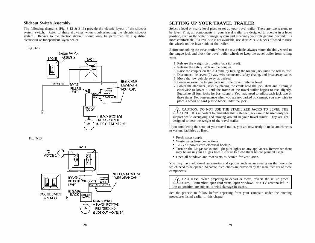
Slideout Switch AssemblyThe following diagrams (Fig. 3-12 & 3-13) provide the electric layout of the slideoutsystem switch. Refer to these drawings when troubleshooting the electric slideoutsystem. Repairs to the electric slideout should only be performed by a qualifiedelectrician or Independent Jayco dealer.
Fig. 3-12
Fig. 3-13
3130
TV ANTENNARaising Antenna to Operating PositionTurn the elevating crank clockwise in the UP direction about thirteen turns or until someresistance to turning is noted. (Fig. 3-14)
On Amplified models, 12-Volt DC power is required. Turn the power supply ON to useeither the front or rear TV outlet. (Fig. 3-15) Neither outlet will work unless the powersupply switch is on. Turning the power supply on sends 12-volt DC through the cable tothe antenna. The voltage energizes the transistors on the amplifier in the antenna head.The TV signal comes back down the cable to the outlets.
After the antenna is in the full UP position, pull down on the round knob with both handsuntil it disengages from the ceiling plate. Rotate the knob for best picture. (Fig. 3-16)
To Test System1. Make sure the TV set is working properly.2. Switch the power supply ON and OFF to see if there
is a difference in the picture quality while watchingTV. If there is NO difference, refer to manufacturer’smanual for further testing procedures.
�CAUTION: The power supply must be turned OFF when connecting/disconnecting the cables to the power supply and antenna, but must be turned
ON when testing for voltage.
Lowering Antenna to Travel PositionRotate the antenna until the pointer on thedirectional handle aligns with the pointer onthe ceiling plate. Turn the elevating crankcounterclockwise in the DOWN directionabout thirteen turns or until resistance isnoted. The antenna is now locked in thetravel position. (Fig. 3-17)
�CAUTION: When lowering the antenna, never lower it into any positionexcept the TRAVEL POSITION. Failure to lower antenna into the TRAVEL
POSITION before traveling may damage the antenna and is not covered by warranty.
MaintenanceSee “TV Antenna Maintenance” in Chapter 7.
CARBON MONOXIDE DETECTOR(With Generator Option - certain Fifth-Wheel Travel Trailers only)If your towable RV has a generator or generator prep, a carbon monoxide detector will beinstalled on your unit.
Carbon monoxide (CO) is an odorless, colorless, tasteless gas that is extremely dangerousto humans and animals. The following symptoms are indicative of individuals exposed tocarbon monoxide:
Mild Exposure: Slight headache, nausea, vomiting, fatigueMedium Exposure: Severe headache, drowsiness, confusion, fast heart rateExtreme Exposure: Unconsciousness, convulsions, cardiorespiratory failure, death
A UL listed carbon monoxide detector has been installed in your camper. It is designedto detect toxic CO fumes. It is not a substitute for other combustible gas, fire or smokealarms.
Procedures to Take During an Alarm
�WARNING: The activation of the CO detector is a warning thatindicates the presence of carbon monoxide!
�WARNING: Do not disconnect the CO detector to silence the alarm.The detector is designed to sense when the level of CO in the air falls
below the danger level. All individuals should remain outside the unit until thealarm is silent.
• If someone is suffering from an upset stomach, headache or other symptom, immediatelymove to a location that has fresh air. Ensure that everyone is accounted for, includingpets. Call the Fire Department. Do not reenter the unit until the source of carbon mon-oxide has been located and repaired by a qualified technician.
�WARNING: Low levels of CO have been linked to brain and vitalorgan damage to unborn infants with no effect on the mother. Pregnant
women must leave the unit immediately if an alarm is sounded and not returnuntil the unit has been repaired and aired out thoroughly.
• If no one exhibits the symptoms associated with carbon monoxide:1. Push reset button.2. Turn off all sources of combustion including water heater, furnace, stove, oven, and
automobile.3. Open windows and doors and move to a location that has fresh air.4. Call a qualified technician and have the problem corrected before restarting appli-
ances and/or vehicles.
Maintenance/TestingSee “Maintenance and Testing” instructions in Chapter 7. Additional information issupplied in the manual published by the manufacturer of the equipment.
Fig. 3-16
Fig. 3-17
Fig. 3-15
Fig. 3-14
�WARNING: DO NOTconnect high current de-
vices such as hair dryers tothis receptacle. Maximum cur-rent rating of this receptacleis 7.5 amps at 12-volt DC.
3332
Non-Utility Center (Operation)
CITY WATER CONNECTIONWater may be received into the system through a direct hookup referred to as the citywater connection. (Fig. 4-2 or 4-3) After hooking up water hose to travel trailer, openvalve on supply line. Enter coach and open faucets to bleed air from lines. Water will fillwater heater first before supplying lines and faucets. When lines are almost full, you mayexperience some air pockets. Allow them to escape before closing faucets.
�CAUTION: Excessive pressure from water supply systems may be encountered in some parks, especially in mountain regions. Water pressure regula-
tors are available to protect your system against such high pressure. A regulator ofthis type is recommended to prevent damage to plumbing system or components.Not using a water pressure regulator when using city water may cause the o-rings toblow. It is advisable to always use a water pressure regulator when using the citywater connection.
WATER TANK – GRAVITY FILLA water container is permanently installed in your recreation vehicle. On some models itis located inside the travel trailer under a bed, dinette, or sofa. Other models may have anexternal tank under the floor between frame members. To fill the tank, there are two typesof gravity fill connections to the fresh water tank. Fig. 4-1 is the type found on mostmodels. Fig. 4-2 has a combination of gravity fill and city water connection enclosedwhich requires a key to gain access.
The fresh water tank can be filled by removing the gravity fill cap and inserting a gardenhose. Open faucet from water supply and fill tank. You must be careful not to over filltank. This can pressurize the tank, causing leakage and water damage.
�CAUTION: DO NOT leave tank unattended while filling.
CHAPTER 4THE SYSTEMS
PLUMBING SYSTEMIncluded in your Jayco recreation vehicle is a complete fresh water system. Fresh watermay be obtained through two sources: city water connection or gravity fill tank. Thefollowing pages describe the components of the plumbing system.
FIRE EXTINGUISHERA fire extinguisher is installed in each vehicle and is located near the entrance door inthe travel trailer. Be familiar with its location and operating instructions as printed on theextinguisher. It’s too late to become familiar with an extinguisher when an emergency isat hand.
The fire extinguisher is a dry chemical, nonrefillable extinguisher. Do not test thisextinguisher by partially discharging. Doing so will cause loss of pressure making theextinguisher unusable. The extinguisher must be discarded and replaced by a new one ifany use has occurred.
Inspection and MaintenanceTo insure that your fire extinguisher will be ready when needed:
• Read and follow all instructions on label and in owner’s manual.• Inspect the extinguisher AT LEAST once a month - more frequently if exposed to
weather or possible tampering.• Check pressure by pressing in white indicator button. If button does not spring back,
extinguisher will not work properly and must be discarded.• Be sure the yellow lock pin is firmly in place.• Keep the extinguisher clean. Check for dents, scratches, corrosion or any other dam-
age.• Check the discharge nozzle. Make sure it is clean and free of obstructions.
�CAUTION: Under certain fire and heat conditions, the dry chemical powderin this extinguisher (and similar units) will cause damage or prove extremely
difficult to remove from oven surfaces, including self-cleaning models. Do not useself-cleaning feature to remove ABC Powder.
�CAUTION: Avoid inhaling the dry chemical agent. The agent contained inthis extinguisher is not toxic, but may cause skin irritation. In case of contact,
flush affected area with clean, cool water. If irritation persists, contact a physicianimmediately. Chemical name of agent is printed on extinguisher label.
Fig. 4-1 Fig. 4-2
3534
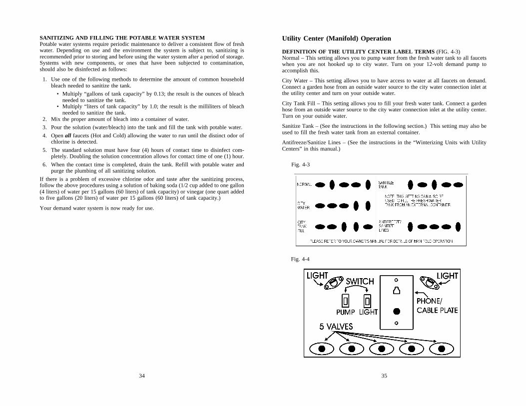
Utility Center (Manifold) Operation
DEFINITION OF THE UTILITY CENTER LABEL TERMS (FIG. 4-3)Normal – This setting allows you to pump water from the fresh water tank to all faucetswhen you are not hooked up to city water. Turn on your 12-volt demand pump toaccomplish this.
City Water – This setting allows you to have access to water at all faucets on demand.Connect a garden hose from an outside water source to the city water connection inlet atthe utility center and turn on your outside water.
City Tank Fill – This setting allows you to fill your fresh water tank. Connect a gardenhose from an outside water source to the city water connection inlet at the utility center.Turn on your outside water.
Sanitize Tank – (See the instructions in the following section.) This setting may also beused to fill the fresh water tank from an external container.
Antifreeze/Sanitize Lines – (See the instructions in the “Winterizing Units with UtilityCenters” in this manual.)
SANITIZING AND FILLING THE POTABLE WATER SYSTEMPotable water systems require periodic maintenance to deliver a consistent flow of freshwater. Depending on use and the environment the system is subject to, sanitizing isrecommended prior to storing and before using the water system after a period of storage.Systems with new components, or ones that have been subjected to contamination,should also be disinfected as follows:
1. Use one of the following methods to determine the amount of common householdbleach needed to sanitize the tank.
• Multiply “gallons of tank capacity” by 0.13; the result is the ounces of bleachneeded to sanitize the tank.
• Multiply “liters of tank capacity” by 1.0; the result is the milliliters of bleachneeded to sanitize the tank.
2. Mix the proper amount of bleach into a container of water.3. Pour the solution (water/bleach) into the tank and fill the tank with potable water.4. Open all faucets (Hot and Cold) allowing the water to run until the distinct odor of
chlorine is detected.5. The standard solution must have four (4) hours of contact time to disinfect com-
pletely. Doubling the solution concentration allows for contact time of one (1) hour.6. When the contact time is completed, drain the tank. Refill with potable water and
purge the plumbing of all sanitizing solution.If there is a problem of excessive chlorine odor and taste after the sanitizing process,follow the above procedures using a solution of baking soda (1/2 cup added to one gallon(4 liters) of water per 15 gallons (60 liters) of tank capacity) or vinegar (one quart addedto five gallons (20 liters) of water per 15 gallons (60 liters) of tank capacity.)
Your demand water system is now ready for use.
Fig. 4-4
Fig. 4-3
3736
To remove excess chlorine odor and taste:1. In a large bucket, prepare a solution of 1/2 cup baking soda to one gallon (4 liters)
of water for every 15 gallons (60 liters) of tank capacity.Repeat steps 3-10 from above.
2. Allow the baking soda solution to sit in the tank for a few days, if possible. If youcan have the soda in the tank while traveling, it will work better to clean and refreshthe tank from the agitating motion.Repeat steps 12-18 from above.
12 Volt DC Demand PumpWhen water is desired and you are not hooked up to city water, you need to turn on the12 volt DC power to start the demand pump. Fig. 4-7 shows a typical demand pump setup. Depending on your travel trailer model, the demand pump will be located under thebed, in a cupboard, under the unit or under the sink. The switch to operate the pump(Fig. 4-8) is located on the monitor panel or a wall near the pump. Energy for the pumpis supplied by the auxiliary battery or converter. The pump will self prime when startedand provide water for your travel trailer. The pump continues to run until approximatelyforty pounds of pressure is achieved and automatically starts again when pressure dropsto twenty pounds. Some cycling in the pump may occur, depending on the volume ofwater being released. A check valve is built inside of the pump to prevent water fromflowing into the supply tank.
NOTE: The water pump switch should be in the off position when the camper is leftunattended for any amount of time. If something would happen to the watersystem, this will ensure that water damage will be restricted to a small area.
SANITIZING UNITS WITH UTILITY CENTER1. Drain the water tank and water heater completely by opening all
faucets and low point drains until tank and heater are empty.2. In a large bucket prepare a chlorine solution using 3/4 cup of
household bleach and three (3) gallons (12 liters) of water.3. Attach the intake hose to the “City Fill Connection” located
inside or under the utility center panel. (Fig. 4-5 or 4-6) Placethe free end in the bucket of chlorine solution.
4. Position the “Control Valves” on the “Utility Panel” to the “Sani-tize Tank” configuration. (Fig. 4-3) The low point drains locateddirectly below the utility center must be closed for the chlorinesolution to siphon through the lines.
5. Turn the “Water Pump Switch (Fig. 4-7) to the “ON” position andpump all of the chlorine solution into the tank.
6. After pumping all the chlorine solution into the tank, position the“Control Valves” to the “City Fill” configuration. (Fig. 4-3)
7. Attach a garden hose to the “City Fill Connection” (Fig. 4-5 or 4-6) and finishfilling the tank.
8. Open kitchen and bathroom faucets to allow air to escape the water lines and thewater heater.
9. Turn the “Water Pump Switch” to the “ON” position and allow several seconds forthe pump to prime. (Fig. 4-4)
10. After the water heater and water lines fill, the air will stop bubbling out of thefaucets. At this point, turn all faucets off. Please note, the water heater will holdapproximately six gallons of water. Allow the water to run long enough to ensurethat the tank is full.
11. Allow to stand for three hours.12. Drain the water tank and water heater completely by turning on all faucets until the
tank and water heater are empty.13. With the garden hose connected to the “City Fill Connection” (Fig. 4-5 or 4-6), refill
the tank with fresh water as in steps 6 and 7.14. Open kitchen and bathroom faucets to allow air to escape the water lines and the
water heater.15. Turn the “Water Pump Switch” (Fig. 4-4) to the “ON” position and allow several
seconds for the pump to prime.16. After the water heater and water lines fill, the air will stop bubbling out of the
faucets. At this point, turn all faucets off. Please note, the water heater will holdapproximately six gallons of water. Allow the water to run long enough to ensurethat the tank is full.
17. Allow to stand for at least three hours.18. Drain the water tank and water heater completely by opening all faucets and low
point drains until tank and heater are empty.
Fig. 4-5
Fig. 4-6
Fig. 4-8
Fig. 4-7
3938
To drain the water supply lines, locate the “low-point” drains as shown in Fig. 4-12.These valves are placed near the floor and may be located under cabinets, dinettes, sofas,beds, or in storage areas. As their name indicates, they will be at the lowest point of waterlines. A label is placed on the outside of the travel trailer to indicate where the drains arelocated. The drains will typically need to be opened from inside the trailer. Once the labelis found on the outside of the trailer, go inside to find the corresponding location of thedrains.
TO DRAIN SYSTEM:1. Open all faucets including the optional exterior
shower.2. Open the fresh water tank drain.3. Open the water heater drain. (Consult the water
heater owner’s manual for details.)4. Open all (2 to 4 depending on the model of your
trailer) low-point drains.5. Open the toilet valve, hold or block it if necessary.6. To empty the pump, start and allow it to run 15-20
seconds.
WATER PURIFICATION SYSTEM (OPTION)A water purification may be installed as an option on your trailer. This system isequipped with a long-life cartridge to effectively reduce chlorine, taste, odor, sediment,organic chemicals and inhibit bacteria growth. If the water system has not been used forsome time, allow water to flow for several minutes to flush the system. When the systemis not in use, store the water filter cartridge in the mounting bracket located near thewater system, or when necessary, out of freezing temperatures.
RV antifreeze will damage the water filter cartridge. The water purification systemmanufacturer has supplied a clear plastic bypass hose with fittings on either end which isdesigned to replace the water filter when the trailer is winterized. The hose should bestored when the filter is in use and kept available to reuse.
The filter should be replaced when water flow is reduce causing an inconvenience, or atleast one time each year.
TO REPLACE THE FILTER:1. Drain the water system.2. Remove the cartridge by disconnecting the fitting at either end of the filter and
pulling it out of the fittings. It may be helpful to have a container available underthe filter to catch any water left in the lines or filter.
3. If winterizing the unit, install the manufacturer supplied bypass hose and store thefilter as is appropriate.
4. If replacing the filter, install the new filter and tighten the fittings at either end.
�CAUTION: Do not allow the filter to freeze or come in contact with RVantifreeze when the trailer water system is winterized. Refer to complete
instructions supplied by the manufacturer.
FaucetsBathroom or kitchen faucets operate the same as inyour home. Open by turning knobs. There may be airin lines which needs to be bled out. Close faucets whensufficient water is released.
Bath and ShowerYour bathroom facilities function similar to those in your home. Prepare bath or showercurtains to prevent water from spilling onto floor. Ensure water heater is in operationbefore bathing. Adjust the faucets for desired temperature before entering tub or shower.
Used water will drain through plumbing pipes into gray water holding tank. Rememberthere are limited capacities in the water heater and gray water holding tank. Long showersin a recreation vehicle are NOT suggested due to the amount of water that is available.
Any tub or shower faucet requires a vacuum breaker when a shower hose and head isused. There are two purposes for this breaker; first to prevent siphoning water throughthe hose from another fixture, and secondly to prevent water from being contained in thehose. The shower head also DOES NOT have a complete shut-off valve. Any drainagefrom either part is normal function and NOT a leak. The complete shut-off is at thefaucet.
Outside Shower (Option)A convenient faucet assembly with hot and cold water isavailable for exterior use washing and rinsing on the outsideof the camper.
OPERATION1. Activate pump.2. Open door with key and allow to hinge down.3. Remove shower head and open valve.4. Open faucet valves and adjust to temperature as desired.5. To cease operation, close valve(s) on faucet and allow
water to drain from shower head.6. Close valve on shower head.
Any water remaining in the hose will drip or run out of vacuum breaker. This is NOT aleak, but performs as intended. Water in A.B.S. plastic box will drain out along outeredge. The shower head can be removed to drain the hose faster. Reassemble and placeonto bracket. Keep the door closed when not in use for sanitary reasons.
DrainageAll permanent fresh water tanks can be drained by one of two types ofdrain valve:
1. A white plastic drain is attached to outer wall. Open valve andallow to drain. (Fig. 4-11)
2. A valve is located inside of coach adjacent to the water tank. Theknob turns 45° to open and close.
Fig. 4-9
Fig. 4-10
Fig. 4-12
Fig. 4-11
4140
Using Toilet and Tank SystemNOTE: For added convenience and better sanitation system performance, it is
advisable to always have four to six inches (10-15 cm) of water in the toilet.
Prior to using the sanitation system, it is strongly recommended to flush the toiletseveral times and release sufficient water into the tank. If there is not a sufficientamount of water used during flushing, the waste materials may not evacuate prop-erly from the drain line to the tank. Clogged tanks and pipes could eventually occur.When camping you should always have four to six inches (10-15 cm) of water in thetoilet bowl. The toilet system will perform better when water is run for ten to fifteenseconds after flushing to ensure that the waste will proceed to the bottom of the tank.Unlike your toilet at home which uses four to seven gallons (18-32 liters) of water perflush, the average recreation vehicle system uses one to three quarts (1-3 liters).
When hooking up to the sewer drain line at a campground, keep the termination valve onthe waste tank CLOSED until the holding tank is at least 3/4 full. This will providesufficient water to assist in the complete draining of the tank. At this time, open thetermination valve to empty the tank and close the valve when the tank is empty. Repeatthis process as needed, but NEVER leave the termination valve open when hooked up tothe park’s sewer system.
VentsAnother important part of the sanitation system are the vents which release air from thetanks. Each tank has a vent pipe built into the travel trailer through the cabinet, wall androof. A vent cap is attached to the roof and must be clear of obstructions to perform asintended. On some models the vent pipe may be part of the drainage system referred to asa “wet vent.” This means water flows downward as air flows upward in the same pipe.
Holding TanksThe final part of your system are the holding tanks. They hold waste and are locatedbelow the floor of your coach. The bath tub and sinks drain into the waste water tank,also referred to as the “gray” water holding tank. The toilet drains into the sewageholding tank, also referred to as the “black” waste holding tank. Certain floor plans mayalso have the lavatory draining into the waste (black) tank.
SEWAGE (BLACK) TANK PREPARATION1. Release one to two quarts (1 or 2 liters) of water into the toilet bowl.2. Following the directions on your toilet chemical bottle by placing the recommended
quantity of holding tank chemical into the bowl.3. Flush the toilet and allow at least two gallons (8 liters) of water to flow into the tank.
�CAUTION: It is important to add enough water to prevent solid waste buildup. Follow these directions each time after emptying your holding tank,
except when winterizing.
SANITATION SYSTEM
ToiletsTwo types or models of toilets are used on Jayco campers. One is the Aqua Magic®
Starlight/Galaxy/Aurora model featuring two foot pedals for flushing. The second type,the Aqua Magic® 4, features two levers on the back side to flush the toilet.
OPERATING INSTRUCTIONS – STARLIGHT/GALAXY/AURORAYour toilet is efficient and easy to operate.Prior to utilizing the unit or after dumpingyour holding tank, add the proper amountof deodorant to tank. Adding a deodorantwill help control waste odors in the tank.After each use, the bowl fills with waterautomatically to a depth of two inches (50mm). To add additional water to the bowl,step on the small pedal and hold it untilthe desired amount of water is in the bowl.Release the pedal slowly (Fig. 4-13). Toflush, step on the large pedal until the rinse clears the toilet bowl, release the pedal slowly(Fig. 4-14). YOU MUST USE AN ADEQUATE AMOUNT OF WATER WHENFLUSHING TO PREVENT SOLID WASTE BUILD UP AND PROMOTE PROPERDRAINAGE. See Holding Tanks.
OPERATING INSTRUCTIONS – AQUA MAGIC® 4The Aqua Magic® 4 is equipped with two operating leverslocated on the right side when facing the toilet. To flush, pullthe black lever (Fig. 4-18) forward (clockwise) until rinse clearsthe bowl and release the lever slowly. Movement of the flushlever opens the waste valve and allows the waste to pass intothe holding tank. The water fill is activated simultaneously withthe black flush lever. The flush lever should be held open forseveral seconds to allow adequate flush water coverage of thebowl to develop. The white water fill lever (Fig. 4-17) can beoperated independently of the black flush lever if more than thenormal two inch (50 mm) automatic bowl refill water is desired.YOU MUST USE AN ADEQUATE AMOUNT OF WATERWHEN FLUSHING TO PREVENT SOLID WASTE BUILD UP AND PROMOTEPROPER DRAINAGE. See Holding Tanks.
MaintenanceSee “Toilets” section under maintenance in Chapter 7.
Fig. 4-14Fig. 4-13
Pull water fill lever (white) to adjustto desired level. Fig. 4-17
Single forward motion flushes andrefills bowl. Fig. 4-18
Fig. 4-15
Flushing lever (black) and waterfill lever (white) shown in thenormal closed position. Fig. 4-16
4342
When hooking up to the sewer drain line in a campground, keep the termination valve onthe waste tank CLOSED until the tank is at least 3/4 full. This will provide sufficientwater to assist in complete draining of tank. At this time, open the termination valve toempty the tank (see directions for draining below) and close the valve when the tank isempty. Repeat this process as needed, but NEVER leave the termination valve open whenhooked up to the park’s sewer system.
To empty holding tank:1. Place the travel trailer as level as possible to make drainage easier.2. Attach a flexible sewer hose to the adapter and secure it with a clamp.3. Remove the cap and attach the adapter onto the valve housing.4. Turn the adapter 10° to lock it onto the pegs.5. Place the other end into an approved sewer system.6. Open the 3" drain valve to drain the sewage tank.7. Open the valve on the gray water tank to utilize the water to wash and rinse the hose.
All drain pipes have a “P-trap” installed into each line. Water in these traps prevent odorsfrom escaping into the travel trailer. During travel, water from the P-traps may spill andpermit odors into the travel trailer. These odors come from food particles decomposing inthe tank. By adding water and using a RV approved deodorizing agent the contents willdissolve faster and will keep the drain lines and tanks clean and free flowing. Chemicalsare available at an RV supply store.
Most states and parks have strict laws and regulations to prohibit dumping of wastes ofany kind into anything other than proper disposal facilities or sewer systems. Almost allprivately owned parks have either a central pump facility or offer a campsite hookup ofsewage. You can find lists of many dump facilities throughout the United States inWoodall’s, Rand McNally Camp Guide, Good Sam Camp Guide, KOA KampgroundsCamp Guide, and various other publications. Some fuel stations also have dump stations.
WINTERIZING TRAVEL TRAILERPreparing your recreation vehicle for winter is very important for most states and Canada.Failure to prepare the coach will cause the supply lines and the water heater to freezecausing breakage. Repairs due to freezing will not be covered under the terms of yourJayco Limited Warranty.
Please keep in mind that your towable RV was not designed for use during sub-freezingweather.
There is no commodity or product that can be added to the fresh water system to ensure freezeprotection while the system is in use, other than RV antifreeze. Do not drink water thatcontains antifreeze. This includes non-toxic RV antifreeze.
�WARNING: Do not use Ethylene Glycol (automotive antifreeze) orMethanol (windshield washer antifreeze) in your fresh water system.
They are harmful and may be fatal if swallowed.
GRAY WATER HOLDING TANKNo special preparation is required. However, placing a small quantity of chemicals intothis tank, such as baking soda or a Thetford chemical, will reduce odors from foodparticles in the system.
�WARNING: We recommend that you DO NOT travel with waste inyour holding tanks. The weight of holding tank contents are not calcu-
lated into the cargo carrying capacity of the unit and the extra weight willgreatly diminish the cargo weight available to you, possibly causing you toexceed the gross vehicle weight rating of the unit. This can damage suspensioncomponents, such as springs, tires and axles. If your model has the holdingtanks located behind the axles, the weight of a full tank will reduce the hitchweight. Sway and other handling difficulties can be the result of the hitchweight being too light. If you are dry camping and cannot immediately emptythe tanks, use caution when towing and maintain lower speeds for bettercontrol of the trailer until you reach a dumping station. Towing your trailerwith one or more full or nearly full holding tank(s), together with cargo youhave added, may exceed the GVWR of your trailer, causing towing difficultiesand resulting in property damage or personal injury.
DRAINING THE HOLDING TANKSOn the outside of the trailer are labels (Fig. 4-19 & 4-20) that indicate the location of thegray and black holding tank drain. A typical set up of the tank drain and terminationvalves is indicated in Fig. 4-21. Look for the labels to locate the drain and follow theinstructions below to empty the tanks.
Spacemaster Chassis System
Fifth-wheel travel trailers equipped with the SpacemasterChassis System have the holding tank termination valveslocated inside the front trunk as indicated in Fig. 4-22. The drain pipe is located at thebase of the trailer as is shown in Fig. 4-21.
Fig. 4-19
Fig. 4-21
Fig. 4-20
Fig. 4-22
4544
Utility Center with Antifreeze1. Drain the water tank and water heater completely by opening all faucets and low
point drains until the tank and water heater are empty. Make sure all holding tanksare empty.
2. Position the “Control Valves” on the “Utility Panel” to the “Antifreeze/SanitizeLines” configuration. (Fig. 4-6) The low point drains located directly below theutility center must be closed for the antifreeze to siphon through the lines.
3. Attach the intake hose to the “City Water Connection.” (Fig. 4-8)
�WARNING: Do not use Ethylene Glycol (automobile antifreeze) ormethanol (windshield washer fluid) in your fresh water system. They
are harmful and can be fatal if swallowed.
4. Put the free end of the hose into a jug of NON-TOXIC RV Antifreese. You willneed more than one gallon of antifreeze.
5. Turn the “Water Pump Switch” (Fig. 4-7) to the “ON” position and open each faucetuntil the antifreeze flows through. Do not forget to run the antifreeze through thetoilet.
6. Pour at least one cup of antifreeze into each drain to protect the p-traps.7. Before using the water system again, open the valves A, B, and C, then sanitize and
flush the whole system. (See instructions under “Sanitizing – Units with UtilityCenters.)
There are three methods of winterizing your travel trailer based upon the model of yourunit. Please read and understand all instructions before beginning.
Air Pressure (all models)This method will utilize an air hose to blow excess water from the water lines.
1. Make sure all holding tanks are empty.2. Run the pump until it is dry, this will take approximately 15-20 seconds.
3. If your unit has the utility center, make sure that the five (5) valves are set up in theantifreeze/sanitize configuration. (Fig. 4-6)
4. Using an air hose and adapter, blow air through the city water connection.5. Leave the faucets, drains and toilets open. Any remaining water will blow out in
five to ten minutes.6. Pour one cup of NON-TOXIC RV antifreeze into all drain P-traps.
Water Heater Bypass with AntifreezeThis method utilizes a water heater bypass kit, available in most units, to avoid filling theentire water heater with antifreeze.
1. Make sure all holding tanks are empty.2. Turn off the pump.3. Close valves A, B and D. Open valves E and C.4. Drain the water heater and fresh water tank. (Consult the water heater owner’s
manual for details.)5. Put the hose from valve E into a jug of NON-TOXIC RV antifreeze. You will need
more than one gallon of antifreeze.6. Turn on the pump and open each faucet until the antifreeze flows through. Do not
forget to run the antifreeze through the toilet.7. Pour at least one cup of antifreeze into each drain to protect the P-traps.8. Close valve E.9. Before using the water system again, drain and flush the water system. Close valve
C and open valves D, A, and B. Sanitize and flush the whole system. It is now readyfor use.
To winterize: Valves A, B, and D are closed; E and C are open.
4746
Fig. 4-23
LP GAS SYSTEMIt is because of the LP gas system that your RV has the convenience of a refrigerator,stove, water-heater, and furnace. This system has containers that contain the fuel and alsoregulators to control the pressure of the fuel and supplies the gas vapor to the variousappliances. When correctly used, the LP gas system is very effective and will ensure thecomfort and added convenience for your vehicle. This system is also potentially verydangerous and should be used with care.
Liquefied petroleum (LP) is a product that is refined from crude oil through naturalgases. Propane is a colorless and odorless gas that in the liquefied state resembles water.An odorant is added as a warning agent. This is usually a sulfur compound which givesthe gas the rotten egg, stinky, skunk oil odor. It is extremely important to become familiarwith the odor associated with LP gas.
LP gas is stored in a pressurized canister in a liquid state. As the fuel is released from thecanister, it becomes vapor that is needed for the operation of the appliances. In the liquidstate, propane should not run through the appliances. A liquid fuel will damage theo-rings in the valves and also leave a sticky, oily residue causing poor or no operation inthe regulator.
LP Gas ContainerThe tank or “bottle” is a D.O.T. approved container to hold fuel in liquid form, and isnormally a 20# or 30# (9 or 14 kilogams) capacity. The open/close valve is to be closedat all times unless hooked up to the LP gas system or filling the container. When thecontainer is disconnected from the hose, install the valve cover that is attached to thecontainer. This is required by the RV industry, Gas Association, and for your own safety.Do not allow the container (filled or empty) to move or roll around while transporting toand from the filling location.
�WARNING: Because your vehicle has exterior combustion air inlets,all pilot lights, appliances and their igniters, (see instructions), must be
turned off before and during gasoline or LP gas refueling. Laws in some statesrequire this.
Servicing and Filling LP ContainersFilling an LP gas container correctly is very important and should be performed by aqualified person who knows the proper inspection and safety procedures. Any newcontainer must be carefully purged for best performance and must NEVER BE OVER-FILLED.
�CAUTION: DO NOT use tools to open or close the tank valve. HANDTIGHTEN ONLY.
�CAUTION: Never smoke during the filling of LP gas tanks. Keep the RVaway from immediate filling area when possible or extinguish all gas pilot
lights.
LP gas expands 1½% for each 10° increase in temperature. It is imperative to leavesufficient space inside the container to allow for the natural expansion of gas duringwarmer weather. Each LP gas container is equipped with an overfill device built into themain valve. This device must remain open during filling. When the container is filled to80%, the maximum level for safety, a liquid will appear replacing the vapor. Stop fillingimmediately and close both valves; HAND TIGHTEN ONLY.
�WARNING: A LP gas container must never be filled beyond 80% ofits capacity.
If your tank becomes overfilled and is not allowed to “bleed off” before installation to theRV system, it may gain pressure from exposure to direct sunlight and will begin “blowingoff” pressure from the overflow valve. This will be detected by the strong odor aroundthe tanks. Keep open flames away from this area. It is best to find a technician qualifiedin releasing an overfill from the container. If that is not possible, remove the container,take it to a safe area at least twenty-five feet (10 meters) from any source of combustion,and “bleed off” the excess pressure by opening the valve slightly and closing it when thedischarge has been sufficient, one to two minutes.
�WARNING: LP gas cylinders shall not be placed or stored inside thevehicle. LP gas cylinders are equipped with safety devices that relieve
excessive pressure by discharging gas to the atmosphere
�WARNING: Do not bring or store LP gas cylinders, gasoline, or otherflammable liquids inside the vehicle because a fire or explosion can result.
When an LP gas tank gets low, sometimes there is a concentration of garlic-like odorwhich may be mistaken for a gas leak. After a change over to a full tank, the odor usuallywill disappear. If not, turn off the LP gas containers and have the system checked by aqualified technician.
1. Knob to open valve to fill or to use camper.2. Complete valve assembly.3. “10%” valve, small brass knob or slot screw.4. Container mounting stand.
11
22
33
VAPORLIQUID
20%
VAPOR
SPACE
4
4948
A warning label has been placed near the LP gas container. This label reads:
�WARNING
THIS GAS PIPING SYSTEM IS DESIGNED FOR USE OFLIQUEFIED PETROLEUM GAS ONLY. DO NOT CONNECTNATURAL GAS TO THIS SYSTEM. DO NOT FILLCONTAINER(S) TO MORE THAN 80 PERCENT OF CAPACITY.FAILURE TO COMPLY COULD RESULT IN A FIRE ORPERSONAL INJURY. Securely cap inlet(s) when not connectedfor use. After turning on gas, except after normal containerreplacement, test gas piping and connections to appliances forleakage with soapy water or bubble solution. Do not useproducts that contain ammonia or chlorine. AD-34
OPD Overfill ProtectionSupplied with your travel trailer is information that applies to the Type 1 ACME LP GasConnection on your LP gas tank(s). Please read all information contained in the suppliedliterature.
The following instructions will supply information for correct cylinder/valve orientation,regulator placement, hose length, hose routing and cylinder cover placement. Make surethese steps are followed for proper LP gas connections.
DUAL CYLINDER ASSEMBLY WITH BOTTLE RACKON A-FRAME OR FRONT TRUNK
1. Connect the 3/8” low-pressure hose tothe outlet of the two-stage regulator.
2. Place the cylinders on the bracket pro-vided on the A-frame and secure them sothe outlet of the cylinder valves pointoutward from the front of the travel trailer.
3. Using the threaded center rod, positionthe regulator bracket. This centers theregulator between the two cylinders asthey are secured to the base tray.
4. Attach the inverted flare x 11” Type-1pigtail hose to the regulator inlet and theright hand swivel nut to the cylinder valve.
�WARNING: The pigtail hose must be installed to avoid tension orpulling stress at either end of the hose.
�WARNING: Keep the pigtail hose away from sharp edges of thecylinder collar, rigid corners, walls, doors or other compartment struc-
tures including the cover.
NOTE: The regulator is typically installed with the inlet fittings at the same level asthe cylinder outlet valves. Due to bracket design, wing nut clearance or coverrestrictions, the regulator fittings may not be in perfect alignment with thecylinder valves. A variance of two (2) inches (5 cm) above or below the linewill permit the hoses to be properly installed.
TWO CYLINDERS (20# OR 30#) (44 OR 66 KILOGRAMS) IN A RECESSEDCOMPARTMENT OR HOUSING
1. Connect the 3/8” low-pressure hose to the outlet of thetwo-stage regulator.
2. Place the cylinder on the bracket in the recess compart-ment or housing and secure them so the outlet of thecylinder valves are facing the “sidewalls” of the com-partment or housing.
3. Mount the regulator on the center back wall of thecompartment or housing so the vent is pointed down-ward.
4. Attach the 1/4” inverted flare x 18” Type-1 pigtail hoseto the regulator inlet and the right hand swivel nut tothe cylinder valve.
�WARNING: The pigtail hose must be installed to avoid tension orpulling stress at either end of the hose.
�WARNING: Keep the pigtail hose away from sharp edges of the cylinder collar, rigid corners, walls, doors, or other compartment structures
including the cover.
Main Supply Hose – Low PressureThe main supply hose will be attached from the regulator to the brass manifold fitting inthe frame of the travel trailer. The swivel brass nut on main hose will be your final
attachment. Several things to remember each time LP gas container is removed:
1. Check that ALL fittings are tight.
2. Check that ALL connections are tested with leak solution.3. Open the main valve slowly to avoid a fast rush of gas to excess flow valve causing
gas freeze up. If you experience a gas “freeze-up,” close the main valve and wait 15minutes before trying again.
4. Listen carefully - a “hissing” sound longer than one second may indicate a gas leak.Close the valve and search for the leak.
ALL GAS LINES HAVE BEEN CHECKED WITH AIRPRESSURE. DEALERS ARE REQUIRED TO RECHECK ANDADJUST PRESSURE BEFORE DELIVERY TO CUSTOMERS.
3/8" MPT x 1/2" Female FlareSwivel
Fig. 4-24
5150
1. Close ALL the burner valves, controls and pilot light valves.2. Open the main valve on the LP gas container slowly to avoid a fast rush through the
excess flow valve causing a “gas freeze.” If you experience a gas “freeze-up,” closethe main valve and wait 15 minutes before trying again.
3. Listen carefully as the gas begins to flow. If “hissing” is heard for more than one ortwo seconds, close the valve and search for the leak.
4. Light the appliances as needed and directed in the the appliance chapter andsupplemental manuals.
�WARNING: Portable fuel-burning equipment, including wood andcharcoal grills and stoves, shall not be used inside the recreation
vehicle. The use of this equipment inside the recreation vehicle may cause firesor asphyxiation.
This warning label has been located in the cooking area to remind you to provide anadequate amount of fresh air for combustion.
�WARNING: IT IS NOT SAFE TO USE THE COOKING APPLI-ANCE FOR COMFORT HEATING.
1. Cooking appliances need fresh air for safe operation. Before operation: a. Open overhead vent or turn on exhaust fan.
b. Open window.2. Unlike homes, the amount of oxygen supply is limited due to the size ofthe recreation vehicle, and proper ventilation when using the cookingappliance(s) will avoid dangers of asphyxiation. It is especially importantthat cooking appliances not be used for comfort heating, as the danger ofasphyxiation is greater when the appliance is used for long periods of time.
FAILURE TO COMPLY COULD RESULT IN EXPLOSION RESULTINGIN DEATH OR SERIOUS INJURY.
Checking for LeaksPlease refer to Chapter 1, “Safety in Using LP Gas.”
�DANGERIF YOU SMELL GAS
1. Extinguish any open flames, pilot lights, and all smoking materials.2. Do not touch electrical switches.3. Shut off the gas supply at the tank valve(s) or gas supply connection.4. Open doors and other ventilating openings.5. Leave area until odor clears.6. Have the gas system checked and leakage source corrected before using again.7. Make sure everyone is out of the RV.
FAILURE TO COMPLY COULD RESULT IN EXPLOSION RESULTINGIN DEATH OR SERIOUS INJURY.
RegulatorThe regulator is the heart of your LP gas system, withinternal moving parts. Its function is to reduce the highand varied pressure from the LP gas container to a safeand consistent low operating pressure. The inlet is thefirst stage and reduces the container pressure to 10-13pounds. The second stage will reduce the 10-13 poundpressure to an operating pressure of 11" W.C. (WaterColumn) or 6.35 oz. of outlet pressure to the coachsystem. The second stage is adjustable and will need tobe adjusted for precise operation. We suggest thisnormal maintenance procedure be performed once peryear. DO NOT make any attempt to adjust the regula-tor. Have only an authorized and competent technicianmake any adjustments.
�WARNING: LP gas regulators must always be installed with thediaphragm vent facing downward. Regulators that are not in a compart-
ment have been equipped with a protective cover. Make sure that the regulatorvent faces downward and that the cover is kept in place to minimize ventblockage which could result in excessive gas pressure causing fire or explosion.
Be sure that your LP gas regulator is protected from road spray. If water enters the ventin the regulator, it may freeze the pressure controlling diaphragm in the open position sothat the LP gas container pressure is applied to the appliances – a hazardous condition.Be sure to carefully read the instructions given by the manufacturer of the regulator.
Automatic Changeover RegulatorThe automatic changeover regulator allows both gas bottles to be turned on simulta-neously. The arrow on the regulator handle indicates which bottle is in service. When theindicated bottle in service becomes empty, changeover is automatically accomplished tocommence drawing fuel from the other bottle. At this point, the plastic window willdisplay a red signal or flag to indicate the condition. The lever should then be flippedover to indicate service on the other bottle. The first bottle which was depleted can thenbe turned off, uncoupled and taken to be refilled without disturbing the RV gas supply.After refilling, it can be removed and again turned to the “ON” position. When the otherbottle is depleted, the LP gas supply will again be automatically changed back to the firstbottle.
�WARNING: All pilot lights and appliances must be turned OFF duringrefueling of motor vehicle tanks and/or LP gas containers.
OperationAfter the camper is completely set up and you are prepared for camping enjoyment,follow these steps for LP gas operation.
Fig. 4-19
5352
�CAUTION: This detector cannot sound an alarm during the three minutewarm up cycle.
Testing
�WARNING: Test the operation of this detector after the vehicle hasbeen in storage, before each trip and at least once per week during use.
Simply press the TEST switch (Fig. 4-25) anytime during the warm up cycle or while innormal operation. The LED light should flashRED and the alarm should sound. Release theswitch. This is the only way you should testyour LP detector. This test feature checks thefull operation of the detector. If this detectordoes not test properly return the detector im-mediately for repair or replacement.
AlarmThe red LED light will flash and the alarm will sound whenever dangerous levels of gasare detected. The detector will continue to alarm until the gas clears or the MUTE switchis pressed.
PROCEDURES TO TAKE DURING AN ALARM1. Turn off all gas appliances (stove, heaters, furnace). Extinguish all flames and
smoking material. Evacuate the trailer – leave doors and windows open.2. Turn off the LP gas container valve.3. Determine and repair the source of the leak. Seek professional help if necessary.4. Do not re-enter the unit until the problem is corrected.
ALARM MUTEThis feature is activated by pressing the TEST/MUTE button when the detector is inalarm.
1. The red LED light will continue to flash and the alarm will beep every thirty secondsuntil the gas level has dropped to a safe level.
2. The LED light will flash green until the end of the mute cycle.3. If dangerous gas levels return before the end of the mute cycle, the alarm will beep
four times and return to #1.4. After two minutes, the detector will return to normal operation (solid green) or
resound the alarm if dangerous levels of gas remain in the area.
MALFUNCTION ALARMThe microprocessor will activate the malfunction alarm when it detects a fault in thedetectors operation. The LED light will alternately flash red and green, while the sounderbeeps twice every 15 seconds. The mute switch will not function. Remove the detectorimmediately and return it for repair or replacement.
Low Power OperationThis detector will operate normally down to 7-volt DC. Do not operate this detectorbelow 7-volt DC. Additional information is supplied in a manual published by themanufacturer of this equipment.
LP Gas ConsumptionMost gas appliances are operated intermittently. Unless there is heavy use of hot water,the water heater consumption is minimal. During freezing weather and high windconditions, furnace consumption can be extremely high.
LP gas consumption depends upon individual use of the appliances and the length of timeoperated. Each gallon (3.86 liters) of LP gas produces about 91,500 BTUs (46,514kilojoules) of heat energy. Following is a list of typical appliance consumption whenturned on fully for one hour of operation:
NOTE: This chart is an example of a typical system and may not represent the exactsystem in your particular unit.
If you have double bottles on your travel trailer, use only one at a time. Otherwise the gassupply will be drawn equally from both bottles until the supply has been totallyexhausted. Using one bottle until it is empty, then using the second bottle will allow youto fill the empty bottle at your convenience without being totally out of LP gas.
LP DETECTORAll recreation vehicles with an LP gas system with LP gas consuming appliances requirea LP gas leak detection device for safety protection. A converter or auxiliary battery isrequired to supply 12-volt DC energy to operate the leak detector.
�WARNING: Limitations of propane/methane gas detectors:
• This detector will not work without power. Examples causing no power are:an open circuit breaker, a faulty power line connection, a blown or missingfuse.
• This detector will only indicate the presence of propane or methane gas atthe sensor. Explosive gas may be present in other areas.
• This detector may not be heard. The alarm loudness is designed to meet orexceed regulatory standards, however, the alarm may not be heard ifdetectors are located in remote locations or behind closed doors. The alarmmay not be heard by persons who are hard of hearing.
• This detector is not suitable as a smoke or fire detector.• This detector is not suitable for installation in hazardous areas as defined in
the national electrical code.
OperationPower ON Warm Up: When power is first applied the yellow LED light will flash forthree minutes while the detector is warming up. At the end of that time the LED light willturn green indicating full operation. If the detector has detected unsafe levels of gas itwill immediately go into alarm.
Fig. 4-25
5554
GFCIEach travel trailer has a GFCI receptacle installed. These initials mean “Ground FaultCurrent Interrupter.” This special receptacle has been designed to reduce the possibleinjury caused by electrical shock.
An example of ground fault current is the current which would flow through a personwho is using or touching an appliance with faulty insulation and, at the same time, is incontact with an electrical ground such as a plumbing fixture, wet floor, or earth.
This GFCI receptacle will not protect against short circuits or overloads. The circuitbreaker or fuse in the electrical panel which supplies power to the circuit provides thisprotection.
When this GFCI receptacle is tripped, it has interrupted ground fault current caused bysuch things as faulty insulation or wet wiring inside some appliance or equipmentconnected to the circuit. The faulty equipment should be repaired before is it used again.
This special receptacle should be tested monthly while the travel trailer is being used.
TESTING INSTRUCTIONS1. Plug a lamp or radio into the receptacle on the face of
the GFCI.2. Push and release the RESET button.3. The lamp should light at this time.4. Press the TEST button.5. The RESET button should pop out indicating it has
been “tripped” and the lamp should go out. (If theGFCI is manufactured with an indicator light, the lightshould glow when the device has tripped.)
6. If the GFCI did not trip, do not use the outlet. Call aqualified electrician to service or replace the receptacle.The ground fault protection is no longer working andthe GFCI may not be working properly.
7. To restore power after “tripping”, press in the RESETbutton. It must remain in. (If an indicator light is fur-nished, it will be off.)
ELECTRICAL SYSTEMGeneralThe electrical system in your travel trailer is composedof 120-volt AC (alternating current) and 12-volt DC(direct current) capabilities. All installations are madein compliance with safety requirements of ANSI stan-dard A.1192, National Electric Code, and CanadianStandards Association.
All conventional travel trailers and fifth-wheel traveltrailers will have 30-amp service pre-wired into thebreaker box. 50 amp service is standard on DesignerLegacy and an option on Designer models.
�CAUTION: Power surges experienced while plugged in at a campgroundcould potentially damage electronic components in your recreation vehicle.
Damage from power surges are not covered by your Jayco warranty. Consult thecomponent manufacturer’s owner’s manual or your Independent Jayco Dealer forrecommendations on power surge protection.
120-Volt AC SystemPOWER CORDYour travel trailer is equipped with a 30-amp rated power cord pre-wired into the breakerbox or a 50-amp rated power cord that is stored in the front trunk. By opening the cablehatch door you can pull the power cord out from the compartment and attach it to apower source. The power will enter through the main breaker and is distributed throughthe circuit breakers to wall receptacles and any appliances wired directly as an airconditioner would be. The cord extends approximately 20'–23' (7 to 10 meters) from thetravel trailer depending on floor plan.
To prevent accidental electrical shock, insure that the ground pin on the attachment plugcap is intact to the earth ground through the RV park receptacle. Any accidental short ofa live circuit conductor will trip the circuit breaker indicating a shorted circuit. Youshould be certain that the polarity of the external power is not reversed, in order to avoidharm to appliances and personal electrical shock. Polarity indicators may be purchased inmost electrical and hardware stores.
It is strongly recommended to avoid the use of extension cords. If an extension cord isused, it MUST be the same amperage rating as the RV power cord. Using an improperextension cord will cause overheating of the cord and equipment as well as possiblycausing premature failure of the AC equipment.
�WARNING: Do not use an adapter, cheater or extension cord that willbreak the continuity of the grounding circuit connected to the third pin.
NEVER remove the grounding pin to connect a non-grounded, two-prong recep-tacle. Any deviation from this will potentially cause a fire from overheating.
50-amp125/250-volt,
3 pole, 4-wire,grounding type
Fig. 4-26
30-amp125-volt,
2 pole, 3-wire,grounding type
Fig. 4-27
5756
CONSUMPTION OF 120-VOLT AC POWERAs owners desire and purchase more appliances as we have in our home, we mustremember a travel trailer has only 30-amps of incoming power available. Conserving andchoosing which appliance has priority in consumption needs to be part of planning.
In addition, loose items such as toasters, skillets, coffee pots, etc. are often included intraveling cargo. Include these in your consumption planning.
12-Volt DC SystemThe 12-volt DC system is composed of numerous items such as converter, battery, fuses,wire, and bulbs, both interior and exterior lighting. Explanation on these items willfollow in this section.
�CAUTION: For the breakaway switch to be operational, an auxiliary batteryneeds to be installed. Consult with your dealer to purchase the battery and
have it installed.
�CAUTION: Your RV has many 12-volt DC loads. When combined, theytotal more power consumption than is available with the 12-volt DC con-
verter. Periodic overloads can be handled with the additional auxiliary battery forshort periods of time. It is suggested to conserve your 12-volt DC system at mosttimes. Prolonged overload may shorten the performance life of converter.
CONVERTERA converter utilizes 120-volt AC power and transforms this energy into 12-volt DCpower, which is used inside of your travel trailer. 12-volt DC energy supplies power to allinterior lights and various appliances. The floor plan, and size of the travel trailer dictatesthe model and output size of the converter required. Your travel trailer may have dualpower converters.
Inside of the converter is an electronic device which automatically switches between 120-volt AC incoming power and battery power. An auxiliary battery as correctly installedwill be charged when the travel trailer is connected up to 120-volt AC power. Theconverter will supply power through the fuse panel located near by, possibly in the samecompartment.
AUXILIARY BATTERY (Dealer Installed Option)All Jayco conventional travel trailers and fifth-wheel travel trailers are designed and builtto accept a battery. A deep cycle marine type is recommended as you need longer energyrather than cold cranking power. A battery is required to operate the breakaway switchand also provides a source of energy when traveling and camping.
All battery packages require an “in-line” fuse and holder attached to the battery forprotection.
Maintenance on a battery is required for longer life. First, all terminals need to be keptclean and free of corrosion. Second, a battery that is used daily or has the converter inoperation will consume water. Keep the battery filled as the cells cannot hold a chargewhen the water is low. A deep cycle battery is NOT maintenance free.
In normal conditions a converter will not overcharge a battery unless (a) the battery haslow or dead cell(s), or (b) the converter has a malfunction. The charging module on someconverters have a positive shut-off and on others there is a reduced charge rate to a verylow amperage.
30-AMP SERVICEOn a 30-amp system, up to 5 circuits are permitted to distribute power through the traveltrailer. All breakers are sized according to power to be consumed.
�WARNING: Do not replace breakers or fuses with any that are ratedat a higher amperage. Over fusing may cause a fire by over heating the wire.
Below is a generic drawing with circuit breaker alignment. Your travel trailer may not beexactly the same as shown depending on model, floor plan, and options.
50-AMP SERVICEA 50-amp service is available on Designer travel trailers as an option and is standard onLegacy fifth-wheel travel trailers. Below is a generic drawing with circuit breakeralignment. Your travel trailer may not be configured exactly as shown depending onmodel, floor plan, and options.
1 = 30-amp main, incoming power to trailer2 = 20-amp circuit to air conditioning3 = 15-amp microwave oven4 & 5 = 15-amp to general purpose circuits6 = 15-amp service for optional water heater
A = 20-amp air conditionerE – 15-amp water heaterB = 15-amp microwave ovenF = openC = 15-amp refrigerator and utilityG = 15-amp washer & dryerD = 15-amp GFI and kitchen circuitsH = 20-amp air conditioner
5958
1
2
3
4
TUB
E
TUB
E
2
1
4
3
TUB
E
TUB
E
3
4
1
2
TUB
E
TUB
E
4
3
2
1
TUB
E
TUB
E
PORCH LIGHTAny porch light on either sidewall will have switches located on the wall inside of theentrance door.
Front convenience lights on Fifth-Wheel Travel Trailers or Conventional Travel Trailerswill have a switch included with the light assembly and fused through the fuse panel.
Television CableThe television cable is rated RG-6 to accept satellite dishes.
Fluorescent Lighting (Option)Each fluorescent light in the unit contains two eight watt tubes, replacement numberF8T5. To extend the life of the tubes by 30 percent, rotate the tubes once per year per therotation sequence shown below:
Fuse and Bulb ChartFuses: All fuses for the interior of coach and external porch lights are located in the fusepanel. This panel is located near the converter.
�WARNING: Do not replace circuit breakers or fuses with a highercurrent rating than those supplied with the new camper. Over-fusing
can cause a fire hazard by overheating the electrical wiring.
A fully charged battery will read 12.7-volt DC and 1.265 specific gravity at 80°F (32°C).A battery is considered discharged at 11.8-volt DC by electronic standards. When thevoltage drops below these levels, permanent damage will occur.
The interior lights will operate from the converter and/or auxiliary battery. Some lightswill have wall switches and others will have switches in the fixtures themselves.
The RV battery is installed in parallel circuitry with the battery on your tow vehicle.Both batteries supply power to your RV, so it is important not to discharge the towvehicle battery below the level of power required to start theengine. To prevent this occurrence while parked, disconnect thewiring harness between the RV and tow vehicle or install abattery isolator (see below). When the tow vehicle’s engine isoperating with the RV connected, the vehicle’s charging systemwill charge both the vehicle battery and the auxiliary battery.
Designer Legacy Fifth-Wheel Travel Trailers have a battery dis-connect switch as shown in Fig. 4-28. To avoid draining thebattery power, turn this switch off when the trailer is not beingused for a period of time.
BATTERY ISOLATOR (For Tow Vehicle)A battery isolator should be installed for two purposes. First it receives current from thealternator and controls distribution of energy to both batteries. Secondly, it serves as acheck valve to prevent energy from being drawn from tow vehicle chassis battery. Energyin the tow vehicle is now preserved to start your engine.
Two types of isolators are available, mechanical and solid state. Each type has anamperage rating (70-amp per side) to indicate it’s capacity of operation. The solid statetype of isolator, although typically more expensive, will provide the best overallperformance. Your dealer can assist you with purchase and installation.
EXTERIOR LIGHTSAll exterior lights are energized by the tow vehicle power, such as tail lights, clearancelights, turn signals, brake lights, etc. When attaching wire leads to a tow vehicle, carefullyand tightly tape all connections for moisture protection.
Refer to diagram (Fig. 4-27) for the color code of the seven wire harness and connector.The connector between the tow vehicle and your travel trailer may build up corrosionwith extended use, and should be cleaned periodically to insure good electrical contact.
BrakesThe electric brakes operate on 12 volt DC power from tow vehicle through blue andwhite wires on 7 way pigtail and harness. More information on the brakes is found inChapter #3.
Solar Panel Prep(DESIGNER AND DESIGNER LEGACY FIFTH-WHEEL TRAVEL TRAILERS ONLY)All Designer and Designer Legacy Fifth-Wheel Travel Trailers are equipped with wiringfor Solar Panel installation. Please consult with your Independent Jayco Dealer forassistance with installation of solar panels.
Changes, Modifications and AdditionsAny changes or additions made after delivery may cause a hazardous condition. Consultyour local authorized dealer prior to making any changes, modifications or additions.Only qualified electrical technicians should attempt to make changes or additions to theelectrical system, using only approved materials, components, and employing approvedmethods of installation, which meet safety and code requirements.
�CAUTION: Any electrical installation that does not meet the criteria of themanufacturer’s specification will VOID THE WARRANTY on the electrical
system.
DC Fuse Panel LayoutNote: Below are typical wiring layouts. Your individual travel trailer may be different.
6 & 9 positionFig. 4-30
12 positionFig. 4-31
6362
For Your Safety (Read Before Operating)
�WARNING: If these instructions are not followed precisely, a fire orexplosion may result causing property damage, personal injury or loss of life.
A. This appliance does not have a pilot light. It is equipped with an ignition device thatautomatically lights the burner. Do not try to light the burner by hand.
B. Prior to operation, smell the area around the appliances to ensure that gas has notsettled on the floor.
C. WHAT TO DO IF YOU SMELL GAS• Evacuate all persons from the vehicle.• Shut off the gas supply at the gas container or source.• Do not touch any electrical switch or use phone or radio in the vehicle.• Do not start the vehicle’s engine or electric generator.• Contact the nearest gas supplier or qualified service technician for repairs.• If you cannot reach a gas supplier or qualified service technician, contact the
nearest fire department.• Do not turn on the gas supply until the gas leak(s) has been repaired.
D. Use only your hand to turn a gas control valve. Never use tools. If the valve will notturn by hand, do not try to repair it. Call a qualified service technician. Using forcemay result in a fire or explosion.
E. Do not use the appliance if any part has become wet. Immediately call a qualifiedservice technician to inspect and replace any part of the control system and gascontrol which has been under water.
Operating Instructions1. STOP! Read the safety information above.2. Set the thermostat to lowest setting.3. Turn off all electric power to the appliance.4. This appliance is equipped with an ignition device which automatically lights the
burner. Do not try to light the burner by hand.5. Open the control access panel.6. Turn the valve power switch to “OFF.”7. Wait five minutes to clear out any gas. Then smell for gas, including near the floor.
If you smell gas, STOP! Follow “C” in the safety information. If you do not smellgas, go to the next step.
8. Turn the valve power switch on to the valve.9. Close the access panel.
10. Turn on all electric power to the appliance.11. Set the thermostat to desired setting.12. If the appliance will not operate, follow the instructions TO TURN OFF GAS TO
APPLIANCE (below) and call your service technician or gas supplier.
CHAPTER 5APPLIANCES
GENERALAll appliances in your Jayco RV are name brand quality built equipment, guided bycurrent code and standards. For gas operation, the appliances in your travel trailer willoperate on LP gas only, not on natural gas. All safety precautions for LP gas fromChapter 4 must be followed during operation of the appliances. Please familiarizeyourself with them before proceeding.
Included with each travel trailer are specific operation manuals, written and published bythe manufacturer for each appliance. Refer to these owner’s manuals for additionalinformation not covered in this manual.
FURNACEThe furnace requires both 12-volt DC and LP gas energy for full operation. Thecombustion system is fully sealed. Oxygen is drawn from outside through the center portof the vent by the fan motor. After burning fuel, the carbon monoxide exhaust is expelledinto open air through the outer port of the vent. This vent is NOT to be altered orobstructed in any manner to ensure your personal safety.
In order for the furnace to operate, a fully charged 12-volt DC battery or 120-volt ACpower through a converter must be available.
Two types of thermostats are used in campers. Thermostats are generally installed on aninner wall of a cabinet.
The thermostat in Fig. 5-1 is used for travel trailers which DO NOT have central airconditioning. The furnace is D.S.I. (direct spark ignition) in operation and all functionswill be performed at the thermostat.
The thermostat in Fig. 5-2 or 5-3 are used in traveltrailers with a central air conditioning system. Thefurnace will operate by moving the switch to “heat”position on the system side control. The furnacehas it’s own fan. No movement is needed on the“fan” side.
Fig. 5-1
Fig. 5-2
Fig. 5-3
6564
RANGE AND OVEN OPERATION
�WARNING: Personal Injury Hazard
• Do not touch or allow clothing and flammable materials to come in contactwith burner grates or areas near top burners until they have sufficient timeto cool. These areas become hot enough to cause burns and fires.
• Ensure that pans used are large enough to contain food and avoid boilovers. Heavy splattering or spills left on the cooktop can ignite and causeburns.
• Ensure that glass cookware is safe for use on the top burners. Only certaintypes of glass cookware is suitable for surface or top burner use.
• Never leave top burners unattended.• Turn pan handles inward, but not over other top burners. This will reduce
the chance of burns.• Grease is flammable. Never allow grease to collect around top burners or on
cooktop surface. Wipe spills up immediately.• Do not use water on grease fires. Never pick up a flaming pan. Smother a
flaming pan with a tight-fitting lid or cookie sheet. Flaming grease outsideof the pan can be extinguished with baking soda or a multipurpose drychemical or foam-type fire extinguisher.
To light the top burners on the range and cooktop models equipped with spark ignition:
a. Turn the appropriate burner knob counterclockwise to “ON” or “LITE/HI.” Do notattempt to light more than one burner at a time.
b. On three burner models, turn the “SPARK” knob clockwise one click. If the burnerfails to light, continue turning the “SPARK” knob clockwise until the burner lights.
c. On four burner models, wait approximately seven seconds after turning the burnerknob to “ON”; press the “SPARK” button once to light the burner. If the burner failsto light, continue pressing the “SPARK” button until the burner lights.
d. To extinguish the top burner flame, turn the appropriate burner knob clockwise to“OFF.”
�WARNING: Ensure that stove knobs are pushed all the way onto thestems when in the “OFF” position. Failure to do so could result in the
stove inadvertently being turned on. If camping with small children, you maywant to utilize stove knob covers that are available at your local hardware.
�WARNING: Burn, Fire and Explosion Hazard• Use care when lighting a top burner by hand. If the burner lights
unexpectedly, or your hand is close to the burner, you may be burned.• If any burner should extinguish (after initially lighting or due to accidental
blow-out) turn gas supply off and WAIT FIVE MINUTES before againattempting to light the burner. Failure to follow these instructions mayresult in a fire or explosion.
To Turn Off Gas to Appliance1. Set the thermostat to lowest setting.2. Turn off all electric power to the appliance if service is to be performed.3. Open the access panel (Outer Door Assembly) to turn off the electric switch.4. Close the control access panel (Outer Door Assembly).
MaintenanceSee “Furnace Maintenance” in Chapter 7.
Ducting and Return AirAll heat discharges, registers and return air grills must be free and clear of obstructions.Obstructions will prevent the furnace from performing correctly. This includes allclosable registers that are intended to reduce air flow, not shut it off completely.
6766
Pilot Operation
�CAUTION: Do not tamper with the pilot orifice. High water temperatureand failure of the gas control could result.
1. Turn lighting control (Fig. 5-4B or 5-5B) to “OFF” position.2. Wait at least five minutes to allow gas which may have accumulated in burner
compartment to escape.3. Note that your water heater may have either a “White Rodgers” or Robertshaw
“Unitrol” Control.
FOR “WHITE RODGERS” CONTROL (FIG. 5-4)a. Turn lighting control knob (Fig. 5-4B) to “pilot”
position and hold against stop while lighting pilotburner (Fig. 5-6D)
b. Allow pilot to burn approximately one half minutebefore releasing lighting control knob.
c. Turn lighting control knob (Fig. 5-4B) to “ON”position.
d. If pilot does not remain lit, repeat operation al-lowing longer period before releasing lightingcontrol knob.
e. Set the temperature selection lever (Fig. 5-4A) atthe mark between the warm and hot position.
f. Close access door.
FOR A ROBERTSHAW “UNITROL” (FIG. 5-5)a. Turn lighting control dial (Fig. 5-5B) to “pilot”
position.b. Depress and hold reset push button (Fig. 5-5A)
while lighting pilot burner (Fig. 5-6D).c. Allow pilot to burn for one half minute before
releasing reset push button.d. If pilot does not remain lit, repeat operation
allowing longer period before releasing resetpush button.
e. Turn lighting control dial (Fig. 5-5B) to “ON”position.
f. Set the temperature control dial (Fig. 5-5C) atthe midpoint position between warm and hot.
g. Close access door.4. For complete shut down and before servicing, turn lighting control knob (Fig. 5-4B
or 5-5B) to “OFF” position.
�CAUTION: Setting the temperature control dial at a higher position willproduce water that is hotter, increasing the risk of scalding.
The temperature knob or lever is factory adjusted to its lowest dial setting. It isrecommended that the midpoint position between warm and hot be used. This willprovide for energy efficient operation and sufficient hot water. Valves for reducing pointof use temperature by mixing cold and hot water are available. Consult a licensedplumber or your local plumbing authority.
Oven Operation
�WARNING: Personal Injury Hazard
• Do not touch or allow clothing or flammable material to come in contactwith the inner or outer surfaces of the oven or the oven vent while it is inuse. These areas all are hot enough to cause burns. Allow sufficient time forthem to cool.
• Do not cover the oven vent openings while the oven is in operation. Restrict-ing the flow of combustion air will create an asphyxiation hazard.
Step 1 – To Light the Oven Pilota. Push in the oven control knob and rotate counterclockwise to “PILOT ON”.b. Light the oven pilot located near the back of the oven, under the broiler shelf and to
the left of the oven burner.c. Set the oven control knob to “PILOT ON” to maintain pilot flame. The oven and
broiler are now ready for operation; see Step 2 before proceeding. The oven pilothas been factory set and requires no further adjustment.
d. To extinguish the oven pilot, push in the oven control knob and rotate clockwise to“OFF.” Extinguish all pilots when refueling or traveling.
Step 2 – To Light the Ovena. Light the oven pilot as described in Step 1.b. With the oven control knob set to “PILOT ON,” rotate the knob counterclockwise to
the desired temperature setting or to “BROIL.”c. The oven is equipped with a safety ignition system that requires a minimum of thirty
seconds to operate after turning the oven control “ON.” This delay is normal.d. To extinguish the oven burner, rotate the knob clockwise to “PILOT ON.” The oven
pilot will remain lit.e. For complete shutdown, rotate the knob clockwise to “OFF.”
WATER HEATERSeveral options are available in the water heater appliances. (1.) 6 or 10 gallon (24 or 40liters) capacities, depending on floor plan. (2.) Three types of energy, LP gas only, LPgas and 120-volt AC combination, and 12-volt DC /LP gas combination with 120-volt.Water temperature is adjustable on pilot and 120-volt AC models, but not on thecombination unit.
Fig. 5-4
Fig. 5-5
6968
Electric Operation1. For gas operation refer to Pilot Operation or Electronic Ignition Operation section.2. For electrical operation, use the switch inside the travel trailer in the utility panel.3. Completely fill tank with water.4. Turn switch (Fig. 5-8) located in the travel trailer to the “ON” position.
NOTE: Turning the power on in the heater with little or no water covering the heatingelement may burn out the element and void the warranty.
5. Check for proper operation. Water temperature should be approximately 140°F(60°C).
6. If the manual reset high temperature limit switch should operate, reset the switch(Fig. 5-9) by depressing the button. Use a pencil or other nonmetallic object todepress the rest button. If the malfunction repeats, contact an authorized AtwoodService Center or Atwood Service Department.
When cold water is heated in the tank, the pressure will rise. For this reason, a reliefvalve (Fig. 5-10) is required for safety in all water heaters, rated at 125° (52° C). It isnormal for this valve to release a small quantity of water during the heating cycle.Opening a faucet on the hot side will release pressure reducing relief valve dripping.
PRESSURE TEMPERATURE RELIEF VALVE
�WARNING: Do not plug the pressure-temperature relief valve underany circumstances.
When cold water is heated in the tank, the pressure will rise. For this reason, a reliefvalve (Fig. 5-10) is required for safety in all water heaters rated at 125°. It is normal forthis valve to release a small quantity of water during the heating cycle. Open the hotwater faucet to release pressure which will reduce the dripping from the relief valve.
Flushing InstructionsIf your travel trailer is used frequently, or taken to different areas that use various typesof water, it is recommended that the water heater be flushed periodically throughout theyear to prolong the life of the inner tank. The following procedure summarizes the stepsnecessary for flushing the water heater inner tank.
To adjust Main Burner (Fig. 5-6):
1. Loosen air shutter screw (Fig. 5-6A).2. Slide air shutter (Fig. 5-6B) to the right until a small
amount of yellow color appears in the main burnerflame.
3. Move air shutter (Fig. 5-6B) to left until yellowdisappears.
4. Retighten air shutter screw (Fig. 5-6A).
Electric Ignition Operation1. To turn D.S.I. on press the rocker switch (Fig. 5-7) to the
“ON” position. Light will come on indicating power toboard. As soon as burner ignites the light in switch willgo off.
2. If remote switch light stays on longer than fifteen sec-onds, place remote switch in OFF position and wait fiveminutes.
3. Repeat step one.4. When water temperature reaches the permanent set ther-
mostat, flame shuts down. Reignition will occur whenwater temperature drops to 100° (38°C) auto-matically.
5. For complete shutdown and before servicing:a. Place remote switch in “OFF” position.b. Remove red wire from left hand terminal of
ECO switch (ECO to valve).6. If heater fails to operate due to high water temperature, the heater will go into a
lockout condition (indicator light on). When water cools, reset by placing switch in“OFF” position for at least thirty seconds, then return to “ON” position.
7. If a lockout condition persists contact your dealer, an Atwood service station orAtwood service department.
NOTE: Terminals on switch #2 and 3 supply power to heater. Terminals 4 and 6supply power to light. Some models may have switch for D.S.I. water heatersin monitor panel.
Pilot Re-ignite Operation1. Turn the switch located on the spark module to the “ON” position.2. Read Pilot Operation Instructions.
�WARNING: The pilot relight module and thermostat lighting controlknob must both be in the “OFF” position when refueling the LP tank or
gasoline tank. Fire and/or explosion could result.
3. For complete shut down, turn lighting control knob on thermostat and spark moduleswitch to the “OFF” position.
Fig. 5-6
Located oninside sidewall
Fig. 5-7
ON
OFF
ATWOOD
RELIEFVALVE
A
Fig. 5-8 Fig. 5-10Fig. 5-9
7170
Door SealTo maintain cooling efficiency and prevent excessive frost buildup, the doors must sealcompletely around the entire length of the door gasket. Frequent frost buildup or reducedcooling are indications of air leaks. To check for complete door sealing, lay a long stripof paper or a dollar bill across the flange, against which the gasket seals; then close thedoor. A frictional drag should be felt when withdrawing the paper. Repeat in severalplaces all around the door. If the paper feels loose, the gasket is not sealing. Contact yourdealer or service center.
�CAUTION: Do not use undue force or jerking action when opening therefrigerator door. Air temperature differences can cause a partial vacuum
within the cabinet requiring a firm but steady force to open the door. A sudden jerkcould cause door damage or personal injury.
Battery DrainAs indicated, a 12 volt DC source is required for operation on gas to provide features ofautomatic ignition. The drain on the battery is very low and has little effect on “batteryrun down” unless these switches are left on for long periods of time on a battery with nomeans of recharging. The DC voltage should be checked while operating in the DCmode. The voltage at the refrigerator should never drop below 11.5 volts.
Battery drain should also be considered during times when the refrigerator is stored,defrosted, or occasions when the door is left open. The humidity heater, if left on, draws240 milliamps. Because of this small drain, the NORMAL-STORAGE-HIGH HUMIDITYswitch should be set to the STORAGE position.
Except for DC operation (three-way models) it is evident that the 12 volt DC demand isquite low; nevertheless, the refrigerator should not be operated for long periods of timefrom a battery only, without a means of recharging through the alternator or converter.
Controls
�CAUTION: Never allow water to be sprayed directly on electrical controlslocated behind the inlet vent door. Electrical damage or fires could result.
1. Be attentive when the outer surface is being hosed down to avoid wetting therefrigerator controls.
2. The user should be aware that 12-volt DC is required during all operating modes(AC, GAS, DC).
3. This Norcold refrigerator is equipped with electronic ignition (no pilot flame). Itprovides automatic gas ignition on start up, automatic re-ignition in case of flameblowout and electrical signal to warn of flame failure (red X on annuciator panel).
�CAUTION: Turn off the water heater and allow time for the water to coolbefore removing the drain plug to flush the tank.
1. Turn off your main water supply (pump or water hook-up source).2. Drain the water heater inner tank. Approximately two quarts of water will remain in
the bottom of the tank. This water contains a great deal of the harmful corrosivematerial that has accumulated in the tank.
3. Flush tank with air pressure or fresh water to remove the remaining water.Air Pressure: Air pressure may be applied through the inlet or outlet valve locatedon the rear of the tank or the relief valve (Fig. 5-10) located on the front of the unit.If the relief valve is used, remove the relief valve prior to flushing and insert airpressure through the relief valve support flange.Fresh Water: Pump fresh water into tank with the assistance of an onboard orexternal water pressure. The water may also be hosed into the tank through the inletor outlet valve located on the rear of the tank or the relief valve located on the frontof the unit. Continue this process for approximately five minutes, allowing ampletime for the water to agitate the stagnant water on the bottom of the tank and thusforcing any corrosive material through the drain opening.
4. Close the drain and relief valves.
REFRIGERATORThis appliance in your Jayco recreation vehicle has been designed by its manufacturer tooperate on 120-volt AC electric or on LP gas energy. Its performance depends onnumerous factors such as energy, venting, leveling, humidity and atmosphere temperatures.It is best to cool the refrigerator for eight hours prior to loading it with food. Therefrigerator is not intended for quick freezing or cooling, so be sure to load it withalready frozen/cooled food. Air must be free to circulate withing the fresh foodcompartment. Do not cover the shelves with paper, plastic, etc.
LevelingComfortable vehicle leveling is well within the refrigerator’s operating requirements ofthree degrees off level side-to-side and six degrees off level front-to-back (looking at thefront of the refrigerator). Continued operation outside of these limits can result inirreparable damage to the cooling system.
VentingFor the refrigerator to operate correctly, there are two vents that must be unrestricted inyour travel trailer. The first vent is located in the lower portion of the sidewall. It is ahinged or removable panel that allows access to service compartments on the refrigerator.The second vent is located in the roof of the travel trailer, above the coils on the rear sideof the refrigerator. If the refrigerator is located in the slideout, the upper (second) vent ison the top of the cabinet in the sidewall. Please note, birds might build nests in the vents.It is advisable to retain the screen over the base to prevent this from occurring.
7372
GAS MODE OPERATION• The ON light and the GAS light (Fig. 5- 11- #3 & #4) show in the center display.• This means that the refrigerator is operating on propane gas.If the energy source is interrupted:
• The refrigerator stops operation.• A fault code flashes in the center display.• Refer to the “Fault Codes” section of manufacturer’s owner’s manual.
IGNITION OF PROPANE GAS IN EITHER AUTO OR GAS MODE:NOTE: On initial start up of the refrigerator, ignition of the propane gas may not
occur within 30 seconds.
If ignition of the propane gas does not occur within 30 seconds:
• The gas safety valve of the refrigerator closes.• The refrigerator stops operation.• Refer to the “Fault Codes” section of the manufacturer’s owner’s manual.• The fault code remains until you push the selector switch to the OFF position and then
back to either the AUTO or GAS mode.• If ignition does not occur after two or three times:
• Check the gas supply line.• Consult your local dealer or an authorized Norcold service center.
N621 AND N841 SERIES REFRIGERATORS
Door HandlesDuring travel, the door latch prevents the door from opening. When closing the door,push the door toward the refrigerator until you hear a “click” sound. To open the door,pull the handle away from the refrigerator.
During storage, the storage latch prevents the door from completely closing. Use it toprevent odors when the refrigerator is stored for an extended period of time. To operatethe storage latch, open each door about 1/2 inch (1 cm) and push the storage latch intothe cutout of the strike plate. Do not use the storage latch as a travel latch because thedoors will not be fully closed.
Interior LightThe interior light is at the top of the fresh food compartment. It comes on only when therefrigerator is ON and the door is open. To replace the bulb:
1. Remove the DC power supply wires from the power board at the rear of therefrigerator
2. Remove the cover. On the model N621, pull the cover toward the front of therefrigerator. On the model N841, push the cover toward the rear of the refrigerator.
3. Remove the light bulb from the holder.
NOTE: Use only a GE#214-2 bulb as the replacement bulb. This bulb is available atmost retail automotive parts centers.
Operating the Refrigerator Controls - N611
CONTROL PANELThe refrigerator control panel is between the freezer compartment and the fresh foodcompartment. To maintain the operating control functions of the refrigerator, a 12-voltDC power supply is necessary. The refrigerator and any other DC components in thevehicle receive DC power from the 12-volt system of the vehicle; either an auxiliarybattery, a converter, or the vehicle engine battery.
The selector switch starts (Fig. 5-11 - #1) and shuts down the refrigerator;
• Push the selector switch to the AUTO position to start the refrigerator in auto mode.• Push the selector switch to the GAS position to start the refrigerator on propane gas.The temperature switch (Fig. 5-11 - #2) controls the temperature adjustment of thefreezer and the fresh food compartment. The temperature adjustment that you select doesnot change if the mode of operation of the refrigerator changes.
• Push the temperature switch to the desired temperature setting.• The number “5” is the coldest temperature setting.Refer to the “Display Codes” section of manufacturer’s owner’s manual.
AUTOMATIC MODE OPERATION:When you select AUTO mode, the refrigerator controls automatically select the mostefficient energy source that is available for operation. If a more efficient energy sourcebecomes available, the refrigerator controls change from the current energy source to themore efficient energy source.
The controls select the energy source in this sequence:
• When 120-volt AC is available to the refrigerator:• The ON light shows (Fig. 5-11 - #3) in the center display.• This means that the refrigerator is operating on AC electric.
• If 120-volt AC is not available to the refrigerator:• The ON light and the GAS light (Fig. 5-11 - #3 & #4) show in the center dis-
play.• This means that the refrigerator is operating on propane gas.
Fig. 5-11
7574
Operating the Refrigerator Controls – N621
CONTROL PANEL
The refrigerator control panel is between the freezer compartment and the fresh foodcompartment.
The ON/OFF button (1) starts and shuts down the refrigerator. If the refrigerator is shutdown, press the ON/OFF button to start the refrigerator in auto mode. If the refrigeratoris operating, press and hold the ON/OFF button for two seconds to shut down therefrigerator.
The TEMP SET button (2) controls the temperature adjustment of the freezer and thefresh food compartment. The temperature adjustment that you select does not change ifthe mode of operation of the refrigerator changes. Press the TEMP SET button and thetemperature setting “1-9” appears in the center display (3). Push and hold the TEMP SETbutton and the temperature setting changes. The number “9” is the coldest temperaturesetting.
The MODE button (4) controls the operation mode of the refigerator. Push and hold theMODE button and a light bar flashes in the center display beside each of the fouroperating modes of the refrigerator, one at a time. There is one automatic mode ofoperation, and three manual modes of operation. When the light bar flashes beside themode of operation that you wish, release the MODE button.
AUTOMATIC MODE OPERATIONWhen you select AUTO mode, the refrigerator controls automatically select the mostefficient energy source that is available for operation. If a more efficient energy sourcebecomes available, the refrigerator controls change from the current energy source to themore efficient energy source.
If an energy source is available to the refrigerator, but is not operating correctly: A faultcode appears in the center display. The refrigerator controls try to change to a lessefficient energy source. If a less efficient energy source is not available, the refrigeratorstops operation. Refer to the “Fault Codes” in the manufacturer’s owner’s manual.
MANUAL MODE OPERATIONWhen you select one of the manual modes of operation, the light bar beside the AUTOgoes out in the center display and only the light bar beside either AC, LP, or DC remains.AC means that the refrigerator is operating on AC electric. LP means that the refrigeratoris operating on LP gas. If the energy source is interrupted, the refrigerator stopsoperation. Refer to the “Fault Codes” in the manufacturer’s owner’s manual.
4. Install the replacement bulb.5. Install the cover.6. Connect the DC power supply wires to the power board at the rear of the
refrigerator.
Door AlarmThe refrigerator has an alarm to alert you if the fresh food compartment door is not fullyclosed. The refrigerator continues to operate, but if the fresh food compartment door isopen and the interior light remains on for two minutes:
• An audible alarm starts.• “dr” appears in the center display.• Light turns off.Close the door to silence the alarm.
Backup Operating SystemThis refrigerator has a backup operating system. The backup operating system allows therefrigerator to continue to cool if the temperature sensor of the refrigerator should fail. Ifthis failure occurs, the refrigerator automatically changes to the backup operating system.When you push the TEMP SET button, the temperature setting flashes in the centerdisplay for ten seconds. After the temperature setting flashes, the mode of operationappears in the center display.
NOTE: If you open the door(s) too often, the temperatures inside the freezer andfresh food compartment do not become stable. Allow the refrigerator tooperate for about one hour after each adjustment change before to examinethe contents. The number “9” is the coldest temperature setting.
Have the refrigerator serviced by your dealer or an authorized Norcold Service Center assoon as possible.
Fig. 5-12
NORCOLD AC
AUTO
LP GAS
DC
1-COLD COLDEST-9
ON
OFF
MODETEMP
SET
123 4
7776
If an energy source is available to the refrigerator, but is not operating correctly: A faultcode appears in the center display. The refrigerator controls try to change to a lessefficient energy source. If a less efficient energy source is not available, an audible alarmsounds, and the refrigerator stops operation. Refer to the “Fault Codes” in themanufacturer’s owner’s manual.
MANUAL MODE OPERATIONWhen you select one of the three manual modes, “AU” goes out in the center display andeither AC, LP, or DC appears. AC means that the refrigerator is operating on AC electric.LP means that the refrigerator is operating on LP gas. DC means that the refrigerator isoperating on DC electric. If the energy source is interrupted, an audible alarm sounds,and the refrigerator stops operation. Refer to the “Fault Codes” in the manufacturer’sowner’s manual.
IGNITION OF LP GAS IN EITHER AUTO OR MANUAL MODENOTE: On initial startup of the refrigerator, ignition of the LP gas may not occur
within 30 seconds.
If ignition of the LP gas does not occur with 30 seconds, the gas safety valve of therefrigerator closes.
In the auto mode, the refrigerator control changes to a less efficient energy source (3-waymodels only); the fault code “no” “FL” shows in the center display (2-way models only).
In the manual mode and operating on LP gas, an audible alarm starts, and the fault code“no” “FL” shows in the center display. The audible alarm and the fault code remain untilyou push the MODE button. Push the ON/OFF button two times to stop and start therefrigerator.
If ignition does not occur after two or three times, check the LP gas supply line; consultyour local dealer or an authorized Norcold Serivice Center; change to manual mode andoperate on AC electric, or DC electric (3-way models only).
Ice MakerIce maker is assembled to the refrigerators at the factory as optional equipment. If therefrigerator does not have a factory installed ice maker, one can not be added to therefrigerator at a later time.
ICE MAKER OPERATION1. Open the water shut off valve of the vehicle.NOTE: Make sure that the ice maker arm can move freely and does not touch the
frozen foods in the freezer2. Push the ice maker arm down to the ON position.
�CAUTION: If you operate the refrigerator without connecting the watersupply line and/or opening the water shut off valve of the vehicle, make sure
the ice maker arm is up in the OFF position.
3. Allow the freezer to cool to 32° F (0° C) (a minimum of 24 hours) and iceproduction will begin to fill the storage bin.
NOTE: New plumbing connections and/or impurities in the water supply line afterwinterizing can cause the first ice to be discolored or have an odd flavor.
4. To stop the ice maker, push the ice maker arm up to the OFF position.
IGNITION OF LP GAS IN EITHER AUTO OR MANUAL MODENote: On initial startup of the refrigerator, ignition of the LP gas may not occur within 30seconds.
If ignition of the LP gas does not occur with 30 seconds, the gas safety valve of therefrigerator closes, and the refrigerator stops operation. Refer to the “Fault Codes” in themanufacturer’s owner’s manual. The fault code remains until you push the ON/OFFbutton two times (to stop and start the refrigerator). If ignition does not occur after two orthree times, check the LP gas supply line; consult your local dealer or an authorizedNorcold Serivice Center; change to manual mode and operate on AC electric.
Operating the Refrigerator Controls – N841
CONTROL PANELThe refrigerator control panel is between the freezer compartment and the fresh foodcompartment. To maintain the operating control functions of the refrigerator, a 12 volt
DC power supply is necessary. The refrigerator and any other DC components in thevehicle receive DC power from the 12 volt system of the vehicle; either an auxillarybattery, a converter, or the vehicle engine battery.
The ON/OFF button (1) starts and shuts down the refrigerator. If the refrigerator is shutdown, press the ON/OFF button to start the refrigerator in auto mode. If the refrigeratoris operating, press and hold the ON/OFF button for two seconds to shut down therefrigerator.
The TEMP SET button (3) controls the temperature adjustment of the freezer and thefresh food compartment. The temperature adjustment that you select does not change ifthe operation mode of the refrigerator changes. Press the TEMP SET button and thetemperature setting “1-9” appears in the center display (4). Push and hold the TEMP SETbutton and the temperature setting changes. The number “9” is the coldest temperaturesetting.
The MODE button (2) controls the operation mode of the refigerator. Push and hold theMODE button and each of the four operating modes of the refrigerator flash one at a timein the center display. There is one automatic mode of operation, and three manual modesof operation. When the mode of operation that you wish shows in the center display,release the MODE button.
AUTOMATIC MODE OPERATIONWhen you select AUTO mode, the refrigerator controls automatically select the mostefficient energy source that is available for operation. If a more efficient energy sourcebecomes available, the refrigerator controls change from the current energy source to themore efficient energy source.
Fig. 5-13
NORCOLD
ON
1 - COLD COLDEST - 9
TEMP
SET
MODE ON-OFF
23 14
7978
BBQ GRILL (Option)
�WARNING: The maximum weight limit for the bracket on the side ofyour travel trailer is 50 lbs. This limit includes the weight placed on the
BBQ grill. Exceeding this weight limit could cause damage to the unit andpossibly cause personal injury from hot equipment.
An option for your travel trailer is a BBQ Grill. This grill is for use outside of the traveltrailer and comes with a bracket to attach to the side of the unit. The following list willsupply basic operations for the grill. Be sure to read all instructions included with thegrill.
1. Install the grill bracket on the side of the travel trailer mounting bracket. Make surethat it is securely in place.
2. Place the BBQ grill into the bracket. (Fig. 5-16)
3. Attach the fuel hose to the grill and the LP gas connection located under the traveltrailer by using the “Quick-Coupler” instruction as follows (Fig. 5-17):• Place the handle in the “OFF” position and push back the sleeve. Valve handle
must be in the “OFF” position to make the connection. (Fig. 5-18)• Insert the plug and release the sleeve. (Fig. 5-18)• Push plug until the sleeve snaps forward, locking the plug into the socket.
(Fig. 5-19)• Turn handle to “ON” position to turn gas on. (Fig. 5-20)
4. Open the lid to the BBQ Grill.5. Using an electic match, light the grill using the following procedures:
• Light the electric match.• Insert it into the middle slot on the bottom of the BBQ Grill.• On the grill control knob (Fig. 5-17), depress and turn the knob to the desired
temperature.• The grill should light at this point.
MONITOR PANELThe monitor panel will provide useful information on the capacities of the water tanksand the battery condition. In fifth wheel travel trailers and conventional travel trailers youwill find a wall mounted panel as shown. Follow instructions below regarding operation.
The panel operates on 12-volt DC power supplied by the converter or battery. Sensors areinstalled into the tanks and a resistor assembly relaying a message through wires to thedisplay board on the panel. No power is drawn from the battery unless a switch is pushedor turned on.
OperationFour spring loaded push button switches are located in thecenter of panel. Press only one button at a time, as one set oflights serve all functions. As you push any button, one or morelights will come on, indicating the water level of that tank.
When pushing the battery button, the highest light coming onindicates battery condition. C=charging at 12.7 volts; G=goodat 11.9 volts; F=fair at 11.2 volts; and L=low at 6.0 volts.
The switch at the lower right is for water pump operation. Inthe “ON” position, the pump runs until 45 pounds of pressurehas been achieved. The red light will stay on. Turn the switchoff when the pump is not in use.
The switch in the lower left corner is for direct spark ignition (D.S.I.) water heateroperation if the D.S.I. option is built into your travel trailer.
Fuses for the monitor panel operation are in 12-volt distribution center fuse block.
(Designer Model Option)1. Press TEST spring loaded button to indi-
cate battery voltage and water level in eachtank.
2. Press PUMP button to turn water pump onor off.
3. Press HEATER switch to turn water heateron or off.
Fig. 5-16 Fig. 5-17
Fig. 5-18 Fig. 5-19 Fig. 5-20Fig. 5-15
Fig. 5-14(Eagle/Qwest)
BATTERY
F C
2/3 G
F1/3
E
TANKS
GALLEY
GREY
HOLDING
FRESH
BATTERY
(OPT)
HTR(OPT)
LEDPUMP
L
F
2/3
1/3
E
FRESH HOLDING GRAY 1 GRAY 2 BATTERY
C
G
F
L
TE
ST
PU
MP
HE
AT
ER
8180
Use1. Install the transceivers (Fig. 5-21) with the
PTT (Push To Talk) switch facing out. Thereare four (4) docking bays in the charger toaccommodate up to four handsets.
2. Close and latch the door. The latch can beengaged by gently pressing against the cen-ter of the door.
3. There are four indicator lights on the door.Initally they will "glow" red when power isapplied (ignition switch is "On" or "ACC"position). After the transceiver handset bat-teries are fully charged, the indicators willturn green, indicating the transceivers areready for use. If the indicator light blinksred, try removing the handset and re-insert-ing it into the charger unit.
4. The transceivers may be stored safely in thecharging unit. When the batteries are fully charged, each transceiver will individu-ally switch to "trickle" mode.
How to Operate your Radio
TO RECEIVE:1. Turn the power "On".2. If the "Battery Low" indicator is on, charge the batteries.3. Set the channel selector to the desired channel.4. Adjust the volume control to a desirable listening level by pressing and holding the
monitor button while turning the volume control knob.
TO TRANSMIT:1. Turn the power to "On".2. If the "Battery Low" indicator is on, charge the batteries.3. Set the channel selector to the desired channel.4. To transmit, press the Push to Talk button. Speak slowly and clearly in a normal
voice, approximately 2-3 inches form the microphone. A built-in modulationcontrol circuit will automatically adjust the microphone input level. There is noneed to speak loudly.
5. To receive, release the Push to Talk button.
6. If the grill does not light, turn the gas off, wait five minutes and repeat the abovesteps.
7. Use the temperature control knob to adjust the grill to the desired temperature.The BBQ Grill grate is coated with standard grill enamel and can be cleaned as youwould a grill at home. Underneath the grate, there is a heat defuser. This is formed andventilated to distribute the heat from the burner. Do not use lava rocks in this grill.
To disconnect the BBQ grill, turn the temperature control to the “OFF” position. Reversethe above fuel hose hookup procedures. Wait until the grill is completely cooled, andthen store it in the supplied carrying case. This carrying case will ONLY accomodate acool grill. The grill carrying case has a pocket for accessories such as the fuel hose in thelid. The bracket will not fit inside the carrying case and will need to be stored in aseparate location.
�CAUTION: The BBQ grill must be COMPLETELY cooled before storing toavoid damaging the carrying case.
TWO WAY FAMILY RADIO (QWEST OPTION)
�WARNING: Before operating your family radios and charger, pleaseread all applicable information provided.
�WARNING: Replacement or substitution of transistors, diodes, orother parts of a unique nature, with parts other than those recom-
mended by the manufacturer, may cause violation of the technical regulationsof Part 95 of the FCC Rules, or violation of Part 2 of the rules. Do not use thisdevice in or near a mining facility which used remotely triggered explosives orin an area labeled "Blasting Area". Premature or accidental detonation mayresult. Do not use this device or change battereies in potentially explosiveatmospheres, as sparks in such areas could result in an explosion. Turn yourtranceiver off on board aircraft when requested to do so. This transceivercomplies with FCC regulations for use in the United States. Use in othercountries may be prohibited or restricted by local regulations. Please checkwith the local agency before using this device outside of the U.S.A.
Your transceiver will achieve maximum operating range when communicating withanother transceiver in a flat open area with no trees or buildings obstructing it's signal.Range can be up to two (2) miles under such conditions. Obstacles, such as buildings,trees, or hills may tend to reduce the transceiver's range.
Fig. 5-21
8382
CHAPTER 6CARE OF BODY COMPONENTS
EXTERIOR ALUMINUMYour new Jayco travel trailer has an improved smooth metal with a new polyesterautomotive paint finish. This metal surface may be cleaned and polished as you wouldyour automobile.
�CAUTION: We recommend that you do not take your recreation vehiclethrough automatic car washes and extreme caution should be used if utilizing
any type of pressure sprayer around all attachments, doors, windows, appliancevents, etc. to avoid forcing water inside the unit, possibly damaging components.
FIBERGLASS SIDEWALLSFiberglass walls are very durable and are easy to maintain. To keep them looking nice,wax and buff them once a year. Standard automotive cleaning soaps and waxes work wellfor general cleaning and maintenance. In addition, do not dry wipe surface. Specialcleaners and waxes are available at automotive and RV stores.
Scratches and chips can be easily fixed by an experienced fiberglass repair shop. Anymajor damage should be repaired as soon as possible to keep cracks from spreading.
EXTERIOR ROOF
�CAUTION: All roofs require maintenance. At least once per year, inspectand reseal all seams: front and rear, around all vents, and along all moldings.
If you notice any deterioration in the seal, scrape off any cracked or loose sealantand then reseal the area.
Three different types of roof material are used on Jayco campers: rubber EPDM, TPORoofing or mill-finished aluminum.
Aluminum - The roof is smooth mill-finished aluminum and needs very little mainte-nance. For washing aluminum material, use a mild detergent soap and water solution.Rinse well after washing. Rinse the sidewalls completely to remove streaking.
Rubber - To keep material looking its best simply wash and clean with a sponge, water,and non-abrasive common household detergent. For stubborn stains use a kitchencleanser with bleach. Do not allow the solvent to soak into the rubber material.
TPO Roofing - The proper care, cleaning and maintenance of your TPO Rofing is quitesimple because of the basic properties and longevity of the material itself.
Periodic cleaning is the primary maintenance. The manufacturer suggests using Murphy’sOil Soap with a soft nylon brush or sponge. DO NOT USE solid or granulated cleaners,ash they will marr the natural finish.
DO NOT USE Armor-ALl or other oil/solvent base cleaners as they will leave a slicksurface.
Battery InstallationYour radio comes with four nickel cadmium cells. Remove the cover by releasing theclasp at the bottom of the compartment. Observe the polarity symbols inside the batterytray when installing new batteries. Do not install different types of batteries (standard,alkaline, or different brand rechageable).
�CAUTION: Incorrect battery installation can damage the unit.
Battery Saver ModeYour Two Way Radio has a unique circuit designed to dramatically extend the life ofyour batteries. Four seconds after the transmit button has been pressed, the radio willswitch to battery saver mode, and the LCD display will turn off. The transceiver willremain ready to receive any incoming transmissions while in the battery saver mode.Pressing any of the buttons will illuminate the display and exit the battery saver mode.
8584
DOORS, EXTRUSIONS, WINDOWS & VENTSThese components have putty tape between the component and the wall surface. Portionsof these items may have a cap seal added as a secondary seal. Inspect these seals at leastonce per year. Both putty tape and cap seals can become damaged by U.V. exposure, airpollution, freezing temperatures and exposure to the elements.
Locks on entrance and baggage doors need biannual lubrication. Silicone lubricant isrecommended. Conditions such as rain, salt, dust and pollution may increase the mainte-nance needs.
FURNITUREFor Cloth Furniture: vacuum occasionally to remove dirt, dust and pet hair. Have steamcleaned when necessary. Test fabric in an inconspicuous location before using any spotcleaners.
For Synthetic Leather: wipe with a soft damp cloth for most dirt and spills, air dry. Ifneeded, use a small amount of a mild liquid detergent. For oil or grease stains, sprayimmediately with an all-purpose spray cleaner or Tannery Car Care Cleaner. Take carenot to smear beyond the original stain. Rinse with clean water, air dry.
To Operate Sofa/Recliner Footrest:
1. Make sure cushion is clear of the footrest opening.2. Place heals over the edge of the footrest and pull towards you to release the
safety lock.3. Push down – DO NOT FORCE.
CUSHIONS
�CAUTION: Do not dry clean vinyl components. Do not remove covers fordry cleaning.
If the cushions are dry cleaned, the vinyl on the reverse side of the cushion will shrink,become hard and crack. Vacuum the fabric and wipe the vinyl surfaces. The fabric can begently steam cleaned on the cushions or mats if necessary.
All dinette and bed mat covers are treated with stain protector. Vacuum the cover with abrush attachment periodically to remove dirt.
BEDSPREADSDry clean only.
A good thorough cleaning with some elbow grease and the suggestions above shouldkeep your roff looking good and remove most stains. FOr more stubborn stains, youshould contact your authorized dealer.
If you keep your TPO roof clean, you will be performing the primary maintenancenexessary to keep it looking good and extend its longevity.
Annual inspection of the roof is suggested. Check the membrance for possible damageand check the caulk/lap sealant used in all termination areas and around all accessoriesand fasteners.
TPO Roofing is UV resistant. It will not retain odors or rot.
ALL ROOFS
All corners or flat trim have putty tape sealer between the trim and aluminum skin. Thissealant can be damaged by weather elements for cracking and dry-out conditions. Cleanthe edges and cap seal the edge of molding and skin surface, using sealant recommendedby your dealer. This process should be done at least once per year.
STONE GUARDWash the stoneguard with liquid dishwashing soap or liquid car washing soap and water.Do not use powdered detergent, powdered soap, liquid and spray cleaners or pressurewashing. Wax frequently to protect the surface and make cleaning easier.
ABS PLASTICSABS plastic components such as shower walls, tubs and exterior fenders will retain theiroriginal beauty with reasonable care.
For cleaning:
1. Dust and wipe clean with soft, damp cloth or chamois, wiping gently.2. Wax or polish with Simoniz,® Aero-Wax,® or Glo-Coat® using flannel or jersey
cloth. After polishing, wipe gently with damp cloth to ground electrostatic chargeswhich may attract dust particles.
DO NOT use gritty or abrasive particle soaps or scouring compound to clean ABSplastic.
�CAUTION: Avoid using “Citrus” or biodegradable cleaners which contain“D-Limonene.” They will damage plastic materials.
FRAMEThe frame of your Jayco recreation vehicle is painted with a high-quality, environmen-tally friendly water based paint. Sand, pebbles, objects on the highway, climate (salt airexposure) or ice inhibiting chemicals used during the winter months will damage thepaint, inviting rust and other deterioration. Periodically inspect the exterior exposedareas, clean and repaint the steel members, as necessary, to insure protection. If rustoccurs, the frame should be cleaned and painted. We recommend the use of Rust-Oleum® Rusty Metal Primer and Rust-Oleum® gloss black paint. Simply follow thedirections on each can. To prevent rust or corrosion, you may wish to purchase acommercially available treatment application such as Ziebart®, etc.
8786
WINDOW TREATMENTSThe window treatments of your recreation vehicle may include mini blinds, pleatedshades, and/or drapes. Refer to the following guidelines for cleaning.
Window Treatment Light Cleaning Extensive CleaningMini Blinds Dust or Vacuum May be removed and
washed with a milddetergent and warm water.
Pleated Shades Vacuum A professional drycleaning service isrecommended.
Privacy or Vacuum ProfessionallyCab Area Draperies Dry Clean
�CAUTION: To prevent scorching of the window shades, do not use theswivel arm lamps located adjacent to the slideout if one of the lampshades is
broken or missing. Remove the light bulb and contact a qualified service center forrepairs or replacement.
SHOWER CURTAIN AND LINERThe shower curtain is made of a cotton or cotton/polyester material and should be drycleaned. The shower curtain liner should be cleaned as you would clean your own showercurtain liner at home.
TIRE COVERS - VINYL (Optional)To minimize the possibility of the tire “bleeding” through onto the tire cover, use aseparator (garbage bag, paper cloth, etc.) between the tire and cover.
PANELINGThe wall paneling in your travel trailer is a vinyl covered wood panel. If deep scratchesoccur, putty sticks can be used to cover them. These can be obtained from hardwarestores and lumber yards. For decor paneling, replacement vinyl covering can be pur-chased for repairs if needed. Your dealer’s parts department can assist you with this.
To clean, use a mild solution of soap and lukewarm water with a soft sponge or cloth.DO NOT use abrasive cleaners. It could cause the vinyl to scratch and turn dull. Greasespots and stubborn dirt can be cleaned off with an all-purpose spray cleaner. Harshcleaners and organic solvents can attack the printed vinyl and, therefore, are not recom-mended.
VINYL FLOORTo care for the vinyl floor covering, use a damp mop with water and a mild cleaner. DONOT SOAK FLOORING. Use care to avoid wetting carpet edges.
�CAUTION: To avoid problems of “yellowing” linoleum, the manufacturerrecommends to avoid using cleaners that contain oil based solvents (i.e.
WOOD FLOORUse a cleaner formulated for wood floors.
BATHROOM TUBS, LAVATORY SINKSThe bath tub in your Jayco travel trailer is made of ABS plastic material. DO NOT useabrasive type cleaners, as they may scratch surfaces. Use a mild detergent soap and warmwater to clean the tub surface. These cleaning instructions are similar to those recom-mended for fiberglass tubs and walls. For any type of repair work, see your authorizedJayco dealer.
CARPETINGIf your travel trailer contains carpeting, vacuum frequently. Professional steam cleaningfor tough and deep stains is recommended. Use spot removers for minor spills. ALWAYSTEST CARPET FOR COLOR FASTNESS in an inconspicuous area before using anyproduct.
NOTE: Avoid chemical cleaners. DO NOT permit cleaners to touch carpet or fabrics.
COUNTERTOPS
High Pressure LaminateGlass rings, food spills, water spots and smudges usually wipe off with a damp sponge.Stubborn stains can be removed with a general purpose spray cleaner. Some stains can beremoved by squeezing fresh lemon juice over the stain and allowing the juice to soak forapproximately forty-five minutes. After forty-five minutes, sprinkle baking soda over thelemon juice and rub with a soft cloth.
8988
CHAPTER 7MAINTENANCE/STORAGE
Your new Jayco travel trailer is designed to be as maintenance free as possible. However,maintenance is important to retain its condition as near new as possible. Proper mainte-nance will give you many trouble-free miles.
NOTE: Some areas in this chapter may not be applicable to your travel trailer.
SLIDEOUTYour Power Gear slideout system has been designed to require very little maintenance.To ensure a long life of your slideout system, read and follow these simple instructions.
�CAUTION: Do not work on your system unless the battery is disconnected.
• When the slideout is extended, visually inspect the inner slide rail assemblies(Fig. 3-6 in Chapter 3). Check for excess build-up of dirt or other foreign material; re-move any debris that may be present.
• If the system squeaks or makes any noise, apply a coat of lightweight oil to the driveshaft and roller areas. (Fig. 3-6 in Chapter 3) Remove excess oil so dirt does not build-up.
• On travel trailers with a flush floor slideout, a light coat of silicone spray is recommendedone time per year. To apply the spray, lift the carpet flap. Using a light coat of spray,make one pass all along the glide bar. It is recommended that this be done prior to eachcamping season.
�CAUTION: Use only a silicone spray to lubricate the glide bar. Otherlubricants may attract dirt and oils which will stain the carpet.
• If you have any problems or questions consult your local Jayco dealer or call Power Gear1-800-334-4712.
CARBON MONOXIDE DETECTORTesting
�WARNING: DO NOT attempt to test the detector by any other meansthan using the “test” button. DO NOT attempt to produce carbon
monoxide to test the detector.
The CO detector should be tested weekly for proper operation:1. Push the test button until the yellow LED lights and a short beep is heard for
approximately three seconds.2. Release button.
The detector will test itself for proper operation. Upon completion of the self-test, thealarm will sound and each of the LEDs will light for approximately ¾ second. Thedetector will then resume normal operation.
Fiberglass - Designer Legacy Fifth-Wheel Travel Trailer onlyTo clean the fiberglass, use soap and mild detergents for most stains. For stains that aremore stubborn, use a white Scotch Brite pad and a nonabrasive cleaner like Soft Scrub.
It is possible to work with minor scratches yourself. Carefully use a green Scotch Britepad and an abrasive cleaner like Ajax or Comet. Work in an area larger than the affectedarea to blend them together. Use a circular motion. For most stubborn stains/scratches,start with 240-grit sandpaper and follow with the green Scotch Brite pad and abrasivecleaner. Repeat if necessary. If you are not comfortable with these instructions or if youencounter problems, please consult a professional for assistance.
To prevent permanent damage:
• Always use a hot pad or trivets under hot pans or dishes or heat producingappliances such as frying pans.
• Always use a cutting board; never use a knife on the counter top.• Avoid harsh chemicals such as drain cleaners, oven cleaners, etc.• If you use sandpaper, wet the surface area to control dust.• Only have a professional fabricator use power sanding equipment on the special
lightweight materials.• Do not let cleaners with bleach set on the top. Wipe them off promptly.
HARDWARE AND SINK OR SHOWER FIXTURESUse mild dish soap and water to clean these fixtures. Never use harsh chemicals orsprays. A mild solution of vinegar and water works well to remove hard water spots andstains from the sink or shower fixtures.
9190
Fig. 7-1 Fig. 7-2 Fig. 7-3
FURNACE MAINTENANCEPreventive maintenance and safety checks should be performed by a qualified technicianonce a year, or more, depending on the use of the furnace. Failure to properly maintainthe furnace may void the furnace warranty and can result in unsafe furnaceoperation. Preventive maintenance is NOT covered under the warranty. Powershould be disconnected before servicing.
NOTE: To increase motor life, the furnace should be wired directly to the battery.
TOILETS
Aqua Magic® Starlite/Galaxy/AuroraNo routine maintenance is required. To clean toilet, use a high grade, non-abrasive RVtoilet bowl cleaner. Do not use highly concentrated or high acid content householdcleaners or scouring powder, as these products can damage seals and finish. Do not useproducts with chlorine or bleach.
Aqua Magic® 4The Aqua Magic® 4 does not require routine maintenance except for cleaning. In someinstallations the seat and cover can be removed to facilitate cleaning. To remove seat,both seat and cover should be in the open (up) position. Grasp assembly on both sidesand pull away from you in an upward angle of approximately 45°. To reinstall seat andcover, place legs of assembly in rear slots of cover until they are centered on hinge postsand gently push down at approximately 45° until you feel the engagement.
Battery ReplacementUnder normal operating conditions, the battery will last approximately one year. Thedetector has a low battery monitor circuit which will cause the detector to make achirping sound then the red LED to flash every 30-40 seconds for a minimum of seven(7) days indicating the battery is low. Replace the battery when this occurs. Use only 9-volt batteries for the CO detector.
�WARNING: Use only the batteries specified for replacement. Use ofdifferent batteries may have a detrimental effect on the CO detector.
CleaningUse the following procedure to clean the CO detector:
1. Remove the detector from the mounting plate by rotating the detector in thedirection of the “OFF” arrow on the cover.
2. Clean the interior of the detector by using a vacuum cleaner hose and vacuumingthrough the openings around the perimeter of the detector.
3. Wipe the outside of the detector with a damp cloth.4. Replace the detector back onto the mounting plate.5. Test detector using the testing procedure.
Unit ReplacementThe CO detector should be replaced every six years.
TV ANTENNA
Lubricating the Elevating Gear (Fig. 7-1)The elevating gear will need to be lubricated with a liberal amount of silicone spray. Tolubricate, apply the silicone to the elevating gear with the lift in the down position thenrun the lift up and down a few times to distribute the lubricant over the gears.
Lubricating the Bearing Surface (Fig. 7-2)Twice per year or when rotation of the antenna becomes difficult, lubricate the bearingsurface between the rotating gear housing and the base plate with silicone spray. Elevatethe antenna and remove the set screw or plastic plug from the rotating gear housing.Spray the silicone into the hole and around the edges of the gear housing. Rotate the gearhousing until the lubricant coats the bearing surface and the antenna rotates freely.
Lubricating the Rubber Quad Ring (Fig. 7-3)Lubricate the rubber quad ring located on the elevating shaft below the worm gear withsilicone spray at least twice per year to prevent the quad ring from becoming brittleresulting in leaks in the elevating shaft. Refer to the vendor’s owner’s manual forinformation regarding removal of the worm gear assembly.
Lubricate Here
Spray
Around
Edges
Remove Plastic
Plug and spray
lubricant into hole
Wave
Washer
Flat
Washer
Rubber
Ring
9392
STORAGEDepending upon your area and where your unit is stored, your camper may be a target fordamage from rodents and insects. To protect your camper, never leave food inside theunit and ensure that all surfaces are clean. You may want to place rodent control productsin the unit during periods of storage. Mice can do a tremendous amount of damage to thetent, drapes, cushions, etc. particularly during the winter months. Storing units in fieldsmake them particularly inviting to rodents. Periodically inspect your unit during storageand seal off any areas which can offer an entry point to rodents or insects. Pleaseremember to remove any screens or tape you have used to seal openings before you usethe camper again. Special interest publications, such as articles and books offeredthrough TL Enterprises (Trailer Life, Motorhome, etc.) can offer additional and practicaladvice on the proper storage of your camper. Damage from rodents or insects are NOTcovered under your Jayco Limited Warranty.
�CAUTION: When storing your travel trailer, it is recommended that thebattery be unhooked to avoid draining the battery.
LP GAS BOTTLES1. The LP gas bottle or tank must be painted with a light color, such as white or silver
plate, to reflect heat and light.2. Rust, scratches, and/or dents can affect the safety of the bottle or tank. The D.O.T.
requires that a visual inspection is made prior to each filling.3. Any container that has been exposed to fire, leaks or seems damaged should not be
refilled.4. An LP bottle must always be placed in an upright position. Assure that the bottle is
secured in place prior to moving the vehicle.5. The D.O.T. requires that LP bottles be inspected, certified and labeled when it is
twelve years old. (The number of years for certification may vary in your area.)Following the initial twelve-year period, the bottle must be certified every five years.
6. The valve of the bottle or tank must be CLOSED at all times except when it isconnected to the recreation vehicle LP gas system or is being refilled.
7. Inspect the bottle at regular intervals. If there is a problem, have it evaluated by aqualified technician and discard it, if necessary. Verify with your local LP dealerthat all required inspections and certifications have been completed on the LP bottlewithin the correct time period before refilling the bottle.
E-Z LUBE AXLEIf your axle is equipped with the E-Z Lube feature, the bearings can be periodicallylubricated without removing the hubs from the axle. This feature consists of axlespindles that have been specially drilled and fitted with grease zerk in their ends. Whengrease is pumped into the zerk, it is channeled to the inner bearing and then flows backto the outer bearing and eventually back out the grease cap hole.
LUBRICATION PROCEDURES (FIG. 7-4):1. Remove the rubber plug from the end of the grease cap.2. Place a standard grease gun onto the grease zerk located in the end of the spindle.
Make sure the grease gun nozzle is fully engaged on the fitting.3. Pump grease into the zerk. The old, displaced grease will begin to flow back out the
cap around the grease gun nozzle.4. When the new, clean grease is observed, remove the grease gun, wipe off any
excess, and replace the rubber plug in the cap.5. Rotate the hub or drum while adding grease.
NOTE: The E-Z Lube feature is designed to allow immersion. Axles not equippedwith E-Z Lube are not designed for immersion and bearings should berepacked after each immersion. If hubs are removed from an axle with theE-Z Lube feature, it is imperative that the seals be replaced BEFORE bearinglubrication. Otherwise, the chance of grease getting on brake linings isgreatly increased.
NOTE: The convenient lubrication provisions of the E-Z Lube and the oil lubricationmust not replace periodic inspection of the bearings.
Fig. 7-4
9594
COMPONENT MAINTENANCE AVOID
Coupler Use a small quantity of lubri-cant on the moving mechanismand all points of movement inthe actuator to insure ease ofoperation.
Use conventional grease on thehitch ball for ease of operation.
Fifth Wheel Hitch • Inspect all joints and linksfor tightness to prevent loss.Design is such that bolts andnuts can be tight and stillfunction properly.
• Lubricate all moving parts offifth wheel for properoperation.
• Grease top surface of wheelto eliminate wear andfacilitate easier turning.
• Before coupling to trailer,inspect all moving parts offifth wheel. Replace all bentor worn parts.
• Thoroughly inspect unitevery 1,000 miles (1600kilometers).
• Ensure that all installationbolts and nuts are tight.
Wheel Bearings Exposure to any water or con-densation will cause the bear-ings to rust and be damaged.
Never let the bearings run dry.
Never overpack the wheel bear-ing, especially in the middle ofthe hub. It will trap heat andpossibly disperse grease fromthe seals or dust cap.
The wheel bearings in your newJayco travel trailer are pre-greased. It is recommended thatyou repack these bearings at12,000 miles (19,000 kilome-ters) or at the end of eachseason’s camping to prepare forthe winter months ahead.
Use only a multipurpose No. 1or 2 good quality wheel bearinggrease.
If the bearing or cone (race)become pitted, replace anydamaged part.
NOTE: If you are concernedabout heat in the wheelbearings, check themoccasionally while traveling byplacing your hand on the hub.You will be able to hold yourhand momentarily on the hub.
Should it be extremely hot, it isrecommended to have thebearings inspected by aqualified service center.
NOTE: During the break-inperiod (first 500 miles) (800kilometers) your hubs may feelextra warm due to brake shoessetting in with the brake drum.
Lug Nuts Lug nuts must be checked at 10,25 and 50 miles (16, 40 and 80kilometers) when your traveltrailer is new or a tire is re-moved and every 3,000 miles(5000 kilometers) thereafter. Inaddition, the lug nuts should bechecked periodically for safety,especially before long trips,extensive braking, or tirechanges.
Refer to the axle manufacturer’sowner’s manual for completeinstructions for tire changes andproper lug nut torque values.
� W A R N I N G :DO NOT ignore
checking wheel lug nuts.Failure to do so can causewheel loss and an acci-dent.
9796
COMPONENT MAINTENANCE AVOID
DO NOT smoke while chang-ing bottles or any lines.
DO NOT allow connections tobe loose.
LP Gas System Beginning of each camping trip:1. Inspect all gas lines for
crimps and road damage.2. Check all lines and connec-
tions for leakage with soapywater or leak detector.
3. Have the regulator checkedand adjusted to the properpressure once per year by aqualified dealer.
Appliances To care for brushed chrome it isrecommended to clean with amild soap and water. Wipe drywith a soft cloth. Apply a lightcoat of oil such as baby oilperiodically.
Various items on these appli-ances need to be cleaned peri-odically as need be, such asburner orifices, etc. See individ-ual booklets for directions orsee your dealer.
DO NOT use steel wool,ammonia, acids, or abra-sives on chrome surfaces.
COMPONENT MAINTENANCE AVOID
Lubricate the jack by extendingto full down position and insertSAE 30 oil through oil hole intop of jack. Do this severaltimes per season.
Tongue Jack
Excessive quantity of grease.
Excessive oil will run and at-tract dirt.
Fifth WheelLanding Gear
Inspect pad and inner ram peri-odically.Apply silicone spray to the innertube, pad and inside of handlealignment tube yearly.Grease gears in the gear box andat the top of each leg with extremepressure grease yearly.Oil the shaft bushings with SAE30 oil yearly.Clean electrical connections withbaking soda, then cover with athin coat of grease twice a year.
It is very important to checktires often as noted in Chapter3.
Tires DO NOT ignore checking tirepressures often.
Change Tire& Wheel
To raise coach, place jack(hydraulic or screw) underneathmain frame rail, which spansfrom front to rear, just inside oftires. Use jack stands or solid-blocking for safe support. Placejack just ahead of front tire orjust behind rear tire.
You may wish to loosen (only)lug nuts before raising coach.Remove lug nuts after tireclears ground.
Never raise the travel trailer byplacing the jack under the axlebeam, springs or any attach-ment parts.
Brakes It is important to have brakesadjusted between 200-1,000miles (320-1600 kilometers)after initial break-in period by aqualified technician. Thisoperation may or may not beincluded as part of selling price.
After the initial break-in period,you should adjust the brakesafter each 3,000 miles (4,800kilometers) or at the beginningof each season’s camping trips.
It is very important to keepbrakes adjusted. Poorly adjustedbrakes will not functioncorrectly. Under adjustment cancause an adjuster wheel to fallout.
Brake Linings Refer to the manufacturer’sowner’s manual for instruc-tions on maintenance and re-pair for the brake linings.NOTE: Canadian transpor-tation laws require that brakelinings be replaced if thereis any cracking for semi-trac-tor and trailers only. Thisdoes not apply to recreationvehicles.
Not resealing once per year.Roofs All roofs require maintenance.At least two times each year,inspect all seams: front, rear,around all vents, and along allmoldings for voids, lifting, peel-ing or cracking. Reseal as nec-essary or at least one time eachyear. If you notice any deterio-ration in the seal, scrape off anycracked or loose sealant andthen reseal the area.
COMPONENT MAINTENANCE AVOIDSealants All sealants used in construction
can deteriorate from U.V.exposure, air polution, freezingtemperatures and other exposureto weather elements.
Tape sealants used arounddoors, windows, and extrusionsare subject to dry out conditionsby sunlight and will allow waterseepage when they deteriorate.
Inspect sealants at least twotimes each year and look forvoids and/or dried out, crackingor peeling conditions. SeeFig. 7-5 or 7-6. Inspect alllocations as indicated in Figures7-8 or 7-9. Reseal as necessaryor at least one time each year.Contact your dealer for theappropriate sealant to use.
Using poor quality sealing ma-terial.
Failure to reseal sealant andputty tape.
Clearance Lights Inspect all exterior lights to makesure they do not have moisturetrapped inside. The “weep”holes at the bottom of the lightsmust be kept open to allow mois-ture to escape from the lightfixture.Inspect and seal corners of thedoor frame threshold one timeeach year. Fig. 7-7
Entrance Door
Fig. 7-5
Fig. 7-6
Fig. 7-7
101100
MAINTENANCE CHECKLISTPrior to First Trip
� Check LP gas lines for leaks. Refer to Chapter 4.� Test carbon monoxide detector (if applicable)� Test LP gas detector. Refer to Chapter 4.� Sanitize fresh water system. Refer to Chapter 4.� Check wheel nuts at specified intervals to listed torque values. Re-torque as
needed. Refer to the axle manufactuer’s manual or Chapter 3.� Open all windows and the door and start the furnace. Leave the windows and
door open and the furnace on until the odor from the initial use of the furnaceis fully dissipated.
First Two-Hundred Miles� Check wheel nuts at specified intervals to listed torque values. Re-torque as
needed. Refer to the axle manufactuer’s manual or Chapter 3� Have brakes adjusted by a qualified service technician.
Each Trip� Test LP gas detector. Refer to Chapter 4.� Check battery water level. (If equipped with battery.)� Check tire pressure and wear. Make sure the tires are cold when checking the
tire pressure.� Check running lights.� Inspect safety chains for signs of wear.� Test brakes.� Flush out water heater tank.
After Every Tire Change� Tighten wheel nuts to specified torque values at 10, 25 and 50 miles (16, 40,
and 80 kilometers) to assure that they are correctly “seated” after the tirechange. Refer to the axle manufactuer’s manual or Chapter 3
Daily� Recharge battery after each use.� Ensure LP gas detector operation light is green in color.
Weekly� Test LP gas detector.� Check tire pressure and wear. Make sure tires are cold when checking the tire
pressure.Monthly
� Clean and lubricate the coupler.� Check fire extinguisher pressure. Refer to the fire extinguisher label for
specific instructions.� Test the ground fault circuit interrupter (GFCI)
Every Three Months or 3,000 Miles� Compare water heater pilot flame with ideal flame. Refer to the water heater
owner’s manual for ideal flame. Have cleaned and adjusted as necessary by aqualified technician.
� Have furnace inspected and serviced by a qualified technician.� Apply silicone spray to the fifth-wheel landing gear inner tube and pad and
the inside of the handle alignment tube.� Grease gears in the gear box and at the top of each leg of the fifth-wheel
landing gear with extreme pressure grease.� Oil the shaft bushings of the fifth-wheel landing gear with SAE 30 oil.� Inspect and reseal, as necessary, all sealant and putty tape. Refer to informa-
tion earlier in this chapter.
Every Six Years� Replace carbon monoxide detector. (if applicable)
Prior to StorageNOTE: If storing for the winter, be sure all winterizing steps are followed. Refer to
winterizing section.
� Drain and flush all holding tanks; fresh water, gray water, black water and hotwater tanks.
� Drain all water lines.� Close the LP gas tank valve(s). If your tanks do not already have a cover,
consider purchasing at least a vinyl LP tank cover. Make sure the regulator iscovered.
� Disconnect 120-volt electric power to the RV.� Remove all batteries from the RV and store in a place where they won’t
freeze. Batteries that have been frozen will never hold a proper charge.� Check your roof and other surfaces to ensure there is no damage and potential
leakage that might otherwise go unnoticed until it is too late.� Inspect and reseal, as necessary, all sealant and putty tape. Refer to informa-
tion earlier in this chapter.� Turn off 12-volt/120-volt/LP gas to the refrigerator; defrost and clean. Use
crumpled newspaper or open boxes of baking soda in the refrigerator toeliminate odors during storage.
� Remove all perishable items from the interior. Include in this any items thatare susceptible to freezing, if storing during the winter months.
� Cover all external outlets, such as furnace, exhaust, etc. to prevent “critters”from entering.
� Thoroughly wash the interior and the exterior of your RV.� Close all windows and roof vents.� Cover tires that are exposed to sunlight to prevent weather checking and other
UV damage.� Cover the roof air conditioner.� Consider the purchase of a tarp to cover your RV during storage. Make sure
you invest in a good tarp that can “breathe.� Turn all cushions on edge to prevent the entrapment of moisture/mildew
during long term storage.� Do not use hydraulic leveling jacks during storage.
During Storage Period� Remove snow loads from the top of your RV to prevent causing damage to
the unit’s structure.
� Compare refrigerator pilot flame with ideal flame. Refer to the refrigeratorowner’s manual for ideal flame. Have cleaned and adjusted as necessary by aqualified technician. (RV type refrigerator only)
� Inspect refrigerator door seals.� Inspect refrigerator combustion seals. Have cleaned and adjusted as necessary
by a qualified technician. (RV type refrigerator only)� Check LP gas lines for leaks. Refer to Chapter 4.� Inspect LP cylinders for rust, pits, gouges, scrapes or sharp dents. Repaint
cylinders if rust is present.� Drain and sanitize fresh water system. Refer to Chapter 4.� Check, clean, tighten and lubricate battery cables.� Check wheel nuts at specified intervals to listed torque values. Re-torque as
needed. Refer to the axle manufactuer’s manual or Chapter 3� Examine the tires for unusual wear, sidewall defects from possible cuts,
bulging and abrasions.� Lubricate tongue jack.� Lubricate hitch ball.� Have brakes adjusted by a qualified service technician.
Every Six Months or 6,000 Miles� Clean drains with approved drain cleaners.� Check pipe connections for tightness. Tighten if necessary.� Lubricate all moving parts on the entrance steps.� Lubricate entrance and baggage door locks.� Clean and lubricate stabilizer jacks.� Inspect wheels for cracks, dents or distortion.� Inspect and reseal, as necessary, all sealant and putty tape. Refer to informa-
tion earlier in this chapter.� Have suspension system serviced by a qualified service technician.� Lubricate the elevating gear on the television antenna.� Lubricate the bearing surface between the rotating gear housing and the base
plate on the television antenna.� Lubricate the rubber quad ring on the elevating shaft located on the television
antenna.� Clean fifth-wheel landing gear electrical connections with baking soda, then
cover with a thin coat of grease.
Every Year or 12,000 Miles� Lubricate moving parts on the awning hardware. (Awning option only.)� Manually operate the pressure-temperature control lever on the water heater.� Clean city water entry strainer.� Check demand tank vent for obstructions.� Check water pump connections and mountings for tightness.� Rotate Fluorescent tubes in the light fixtures.� Replace battery on the carbon monoxide detector. (if applicable)� Have LP gas system inspected and serviced by a qualified technician.� Inspect and seal corners at the threshold of the entrance door.� Have the refrigerator inspected and serviced by a qualified technician.� Have brakes inspected and serviced by a qualified technician.� Repack wheel bearings.
105104
Refueling GeneratorLocated in the compartment next to the generator is the generator fuel tank. Follow theseinstructions when refueling the generator fuel tank.
1. Make sure that the tow vehicle and any open flames are extinguished. All pilotlights, appliances, and their ignitors should be turned off before refueling thegenerator fuel tank.
2. Unhook the quick disconnect from the generator fuel hose to the fuel tank.3. Unhook the tie down strap buckle and pull the empty tank from the compartment.4. Lay the fuel tank flat on the ground.5. Unscrew the lid to refuel the tank. The fuel hose nozzle MUST be in contact with
the rim of the fuel tank opening during fueling. Refuel with UNLEADED fuelONLY.
�WARNING: The fuel tank MUST be lying flat on the ground AND thefuel hose nozzle MUST be in contact with the rim of the tank opening
during refueling. There is potential for static charge build up if theseinstructions are not followed which could ignite the gas fumes.
6. When the tank is filled, return the tank to the compartment.7. Secure the tank with the tie down strap. Make sure the strap is tight and the tank
will not move around in the compartment.
�CAUTION: It is important to secure the tank tightly with the tie down strapand make sure the tank will not move around in the compartment during travel.
8. Reattach the fuel quick disconnect to the tank.
�WARNING: Do not carry fuel in this compartment unless the genera-tor is hooked up.
MICROWAVE OVEN / CONVECTION OVENThe microwave oven or convection oven in the unit operate on the same principle as themicrowave/convection in your kitchen at home. A separate owner’s manual is providedwith detailed instructions for its use.
RUBBER ROOFThe heavy-duty rubber roof is durable, does not rumble in the wind, requires no specialtreatment, reduces black streaks on sidewalls, and can be patched if damaged.
To keep your roof looking its best, simply clean it with a sponge and any nonabrasive,common household detergent. For stubborn stains, use a stronger solvent such as xylene,but take care never to saturate.
If your roof is accidently torn or punctured, there’s no need for expensive repairs. Theprocess is much like patching a tire, but we suggest you contact your dealer or Jayco formore information.
As with all trailer roofs, it should be checked at least once a year at roof vents and aroundthe perimeter for signs of cracked or deteriorating sealant. ALPHA 1015 is the best wehave found for roofs. Extend HD works best on horizontal surfaces. Both sealants comein caulking tubes and can be purchased from your Independent Jayco dealer.
CHAPTER 8OPTIONS
NOTE: Each item listed in this chapter is an option as the travel trailer is built by Jayco.
AIR CONDITIONERAir conditioners may be installed by the Jayco factory or by your dealer. If you did notbuy your camper with the optional air conditioner, one of your roof vents may be pre-wired for later installation. Your dealer can provide you with additional informationconcerning this.
There are a variety of air conditioners available. For specific instructions for the airconditioner, consult your dealer and the manufacturer’s owner’s manual.
Some models have Central Air Conditioning available. All cooled air is moved through aduct built into the roof and enters the travel trailer through a group of round registers.
Keep all registers open to insure full airflow. Closing the register(s) may cause thecompressor to freeze, which could shut down the cooling process.
A special foam gasket is placed between the roof material and the subframe of the airconditioner to guard against water leakage.
An air conditioner is subjected to wind pressures along with motor vibration duringnormal operation. Annually inspect the mounting bolts for tightness to ensure there is noleakage or looseness. Retighten bolts when they are loose. DO NOT overtighten thesebolts as it may damage the gasket.
To gain access to the bolts, remove the filtered panel cover on central air systems or theentire air box on non-central air conditioners.
�CAUTION: When camping at campgrounds providing less than 30 ampservice, discontinue air conditioning use when using the microwave.
GENERATORThe function of a generator is to supply 120-volt AC power on a limited basis whenextended power is not available.
The power to start the generator comes from the auxiliary battery. A start/stop switch islocated on a mounting plate with the generator. A remote start switch is located near themonitor panel.
With the exception of simple items such as spark plugs and oil changes, all service workshould be done by authorized service centers. Improper adjustments can damage thegenerator and electrical appliances, and can result in a safety hazard. An authorizedservice center has trained specialists who know how to keep your generator runningsafely and reliably.
107106
TOWABLE TRANSFERABLE LIMITED WARRANTY
CHAPTER 9WARRANTIES
RV DIGITAL SATELLITE SYSTEMThe satellite system in the RV is similar to the satellite system inyour home. The digital elevation sensor switch (Fig. 8-1) is locatedin the ceiling of your trailer. Refer to the detailed instructionsprovided by the manufacturer for additional information.
SPARE TIRE CARRIERThe following procedures should be used in securing the spare tirein the travel position:
1. Put the steel hoist lift support located on the end of the cablethrough the rim of the tire. Clips need to seat inside of the hole.Valve stem of the tire MUST be pointed in the down position or away from thebottom of the travel trailer. Reference Fig. 8-2.The hoist will not seat the tire correctly if the valve stem is toward the bottom of thetravel trailer. Reference Fig. 8-3.
2. Use the crank handle to lift the tire into the travel position. Two crisp breaks mustbe heard and felt to insure proper seating of the tire for travel.
The tire must be in contact with the surface to be in the travel position.
�WARNING: DO NOT exceed the maximum load capacities of 100 lbs.for the hoist. DO NOT use air driven guns or impact wrenches to lift the
tire into travel position.
CEILING FANFifth-Wheel Travel Trailer Option OnlyThe ceiling fan in the unit operates on the same principle as the fan in your home. Aseparate owner’s manual is provided with detailed instructions for its use.
SECURITY LIGHTSThe security lights can be turned on or off from the entry or bedroom switch.
Fig. 8-1
Fig. 8-2 Fig. 8-3
SAMPLECORRECT WAY
TIRE LIFT MOUNTING SURFACE
TIRE CONTACT SURFACE
VALVE STEMdownLift Plate
6 in. Cable
VALVESTEM
UP
LIFT PLATE BOTTOMEDOUT AGAINST LIFT
NOCABLE
TIRE LIFT MOUNTING SURFACE
TIRE NOT IN CONTACTWITH SURFACE
TIRECONTACTSURFACE
WRONG WAY
109108
LIMITED WARRANTY TRANSFER APPLICATIONThe warranty on your unit is transferrable one time only, from the original owner to asubsequent owner. This form as shown here and on the next page must be completed bythe dealership. The form should be sent with the $100.00 to Jayco, Attention: AfterMarket Services.
SAMPLE
SAMPLE
111110
NOTES
SAMPLE
113112
NOTESNOTES
114
NOTES
WELCOME TO THE JAYCO FAMILY!
As the owner of a new Jayco recreational vehicle we are proudto welcome you to our growing family.
All Jayco RV homes are built with care, under the watchful eyeof our Quality Assurance program. And it is our sincere wish thatyou will have a lifetime of fun times with your new Jayco.
We are pleased you chose Jayco and want to do everythingpossible to make sure you stay as happy with your Jayco RV homeas you were on the day you bought it.
We work closely with Jayco dealers to provide customerservice for you. We honestly feel that Jayco dealers are on thewhole the best in the business. And with nearly 300 of them in theU.S. and Canada you should never be too far from help if you everneed it.
In the months and years to come we hope you’ll become aclose member of the Jayco family. One way to enjoy yourJayco even more is through our owners club – the JafariInternational Travel Club. It’s lots of fun and a great way tomeet other members of the Jayco family. If you’reinterested please talk to your dealer about the “flight” inyour area. Or write to us directly and we’ll be in touch.
From Jayco’s family to yours: “Welcome Home!”
®
903 South Main Street • P.O. Box 460 • Middlebury, IN 46540