23
Model ATABD Model ATA BULLETIN 400 February 2006 TUBEAXIAL FANS Adjustable Pitch Airfoil Design Direct Drive/Belt Driven
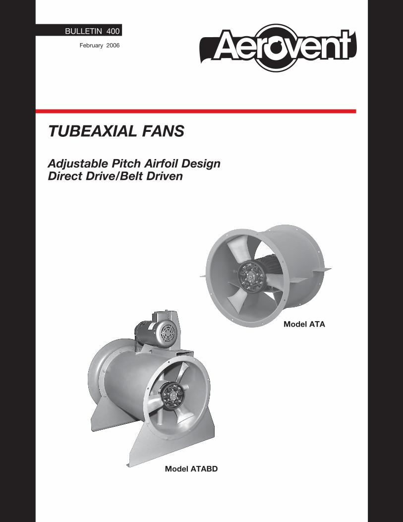
Model ATABD
Model ATA
BULLETIN 400
February 2006
TUBEAXIAL FANS
Adjustable Pitch Airfoil DesignDirect Drive/Belt Driven
2 Aerovent Bulletin 400
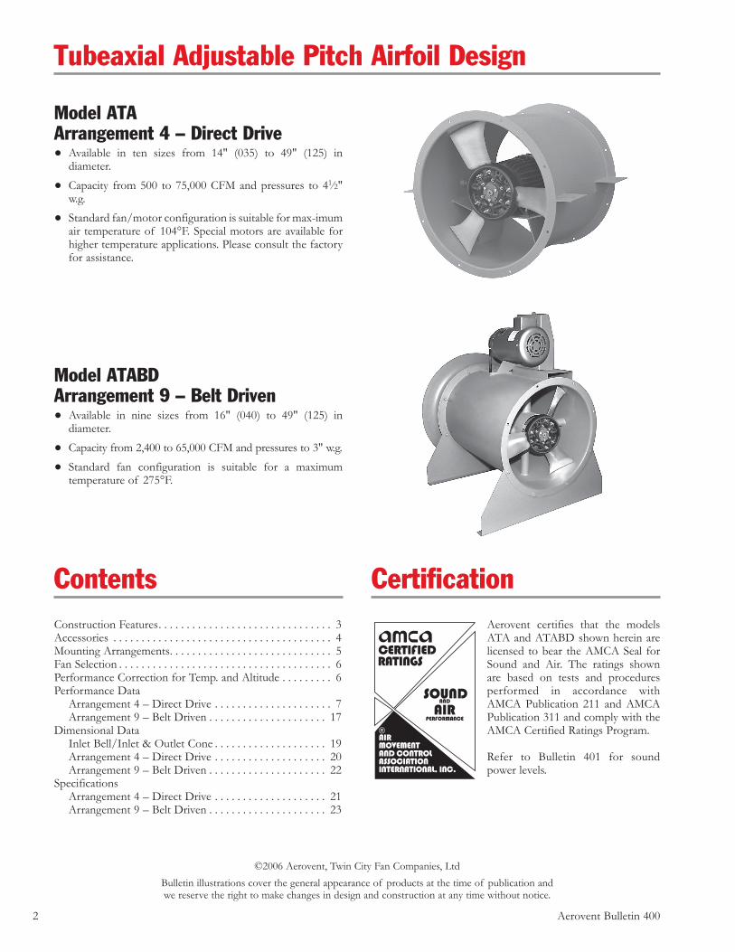
Model ATAArrangement 4 – Direct Drive• Available in ten sizes from 14" (035) to 49" (125) in
diameter.
• Capacity from 500 to 75,000 CFM and pressures to 41∕2" w.g.
• Standard fan/motor configuration is suitable for max-imum air temperature of 104°F. Special motors are available for higher temperature applications. Please consult the factory for assistance.
Tubeaxial Adjustable Pitch Airfoil Design
Model ATABDArrangement 9 – Belt Driven• Available in nine sizes from 16" (040) to 49" (125) in
diameter.
• Capacity from 2,400 to 65,000 CFM and pressures to 3" w.g.
• Standard fan configuration is suitable for a maximum temperature of 275°F.
ContentsConstruction Features. . . . . . . . . . . . . . . . . . . . . . . . . . . . . . . 3Accessories . . . . . . . . . . . . . . . . . . . . . . . . . . . . . . . . . . . . . . . 4Mounting Arrangements. . . . . . . . . . . . . . . . . . . . . . . . . . . . . 5Fan Selection . . . . . . . . . . . . . . . . . . . . . . . . . . . . . . . . . . . . . . 6Performance Correction for Temp. and Altitude . . . . . . . . . 6Performance Data Arrangement 4 – Direct Drive . . . . . . . . . . . . . . . . . . . . . 7 Arrangement 9 – Belt Driven . . . . . . . . . . . . . . . . . . . . . 17Dimensional Data Inlet Bell/Inlet & Outlet Cone . . . . . . . . . . . . . . . . . . . . 19 Arrangement 4 – Direct Drive . . . . . . . . . . . . . . . . . . . . 20 Arrangement 9 – Belt Driven . . . . . . . . . . . . . . . . . . . . . 22Specifications Arrangement 4 – Direct Drive . . . . . . . . . . . . . . . . . . . . 21 Arrangement 9 – Belt Driven . . . . . . . . . . . . . . . . . . . . . 23
CertificationAerovent certifies that the models ATA and ATABD shown herein are licensed to bear the AMCA Seal for Sound and Air. The ratings shown are based on tests and procedures performed in accordance with AMCA Publication 211 and AMCA Publication 311 and comply with the AMCA Certified Ratings Program.
Refer to Bulletin 401 for sound power levels.
©2006 Aerovent, Twin City Fan Companies, LtdBulletin illustrations cover the general appearance of products at the time of publication andwe reserve the right to make changes in design and construction at any time without notice.
Aerovent Bulletin 400 3
Design InnovationThe model ATA and ATABD fan blades have an ever-increasing airfoil chord length from the blade root to the blade tip. The additional chord length is placed at the leading edge rather than the trailing edge of the blade so that when set at an angle, the widest part of the airfoil is at maximum rotational speed in close proximity to the fan casing. This very wide blade tip area allows the ATA and ATABD to maximize energy transfer to the airstream and minimize noise generation. The blade pitch can be individually manually adjusted while the fan is stopped. This feature allows the user to balance the present system while affording the flexibility of further possible pitch adjustment in the future.
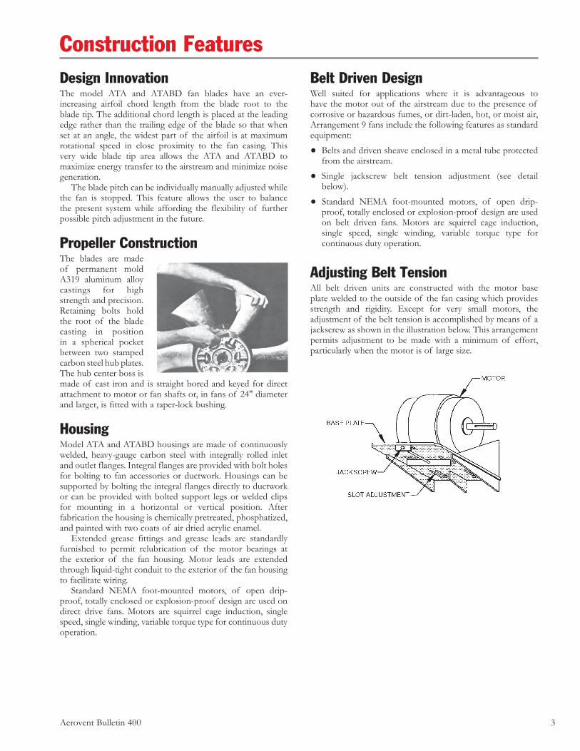
Propeller ConstructionThe blades are made of permanent mold A319 aluminum alloy castings for high strength and precision. Retaining bolts hold the root of the blade casting in position in a spherical pocket between two stamped carbon steel hub plates. The hub center boss is made of cast iron and is straight bored and keyed for direct attachment to motor or fan shafts or, in fans of 24" diameter and larger, is fitted with a taper-lock bushing.
HousingModel ATA and ATABD housings are made of continuously welded, heavy-gauge carbon steel with integrally rolled inlet and outlet flanges. Integral flanges are provided with bolt holes for bolting to fan accessories or ductwork. Housings can be supported by bolting the integral flanges directly to ductwork or can be provided with bolted support legs or welded clips for mounting in a horizontal or vertical position. After fabrication the housing is chemically pretreated, phosphatized, and painted with two coats of air dried acrylic enamel. Extended grease fittings and grease leads are standardly furnished to permit relubrication of the motor bearings at the exterior of the fan housing. Motor leads are extended through liquid-tight conduit to the exterior of the fan housing to facilitate wiring. Standard NEMA foot-mounted motors, of open drip-proof, totally enclosed or explosion-proof design are used on direct drive fans. Motors are squirrel cage induction, single speed, single winding, variable torque type for continuous duty operation.
Belt Driven DesignWell suited for applications where it is advantageous to have the motor out of the airstream due to the presence of corrosive or hazardous fumes, or dirt-laden, hot, or moist air, Arrangement 9 fans include the following features as standard equipment:
• Belts and driven sheave enclosed in a metal tube protected from the airstream.
• Single jackscrew belt tension adjustment (see detail below).
• Standard NEMA foot-mounted motors, of open drip-proof, totally enclosed or explosion-proof design are used on belt driven fans. Motors are squirrel cage induction, single speed, single winding, variable torque type for continuous duty operation.
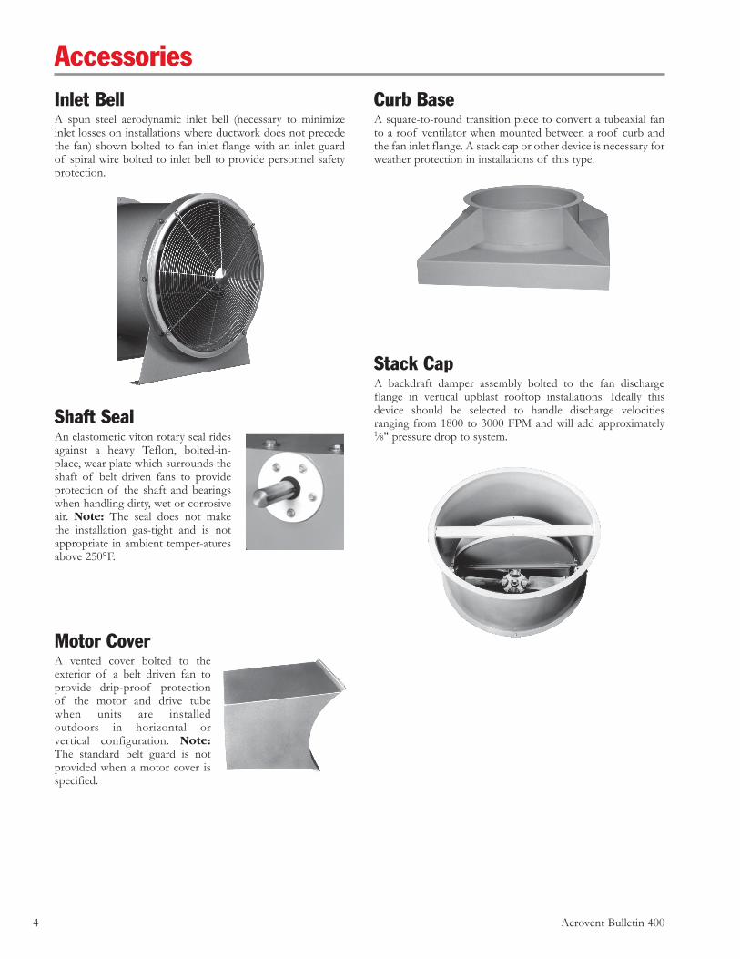
Adjusting Belt TensionAll belt driven units are constructed with the motor base plate welded to the outside of the fan casing which provides strength and rigidity. Except for very small motors, the adjustment of the belt tension is accomplished by means of a jackscrew as shown in the illustration below. This arrangement permits adjustment to be made with a minimum of effort, particularly when the motor is of large size.
Construction Features
4 Aerovent Bulletin 400
Inlet BellA spun steel aerodynamic inlet bell (necessary to minimize inlet losses on installations where ductwork does not precede the fan) shown bolted to fan inlet flange with an inlet guard of spiral wire bolted to inlet bell to provide personnel safety protection.
Shaft SealAn elastomeric viton rotary seal rides against a heavy Teflon, bolted-in-place, wear plate which surrounds the shaft of belt driven fans to provide protection of the shaft and bearings when handling dirty, wet or corrosive air. Note: The seal does not make the installation gas-tight and is not appropriate in ambient temper-atures above 250°F.
Motor CoverA vented cover bolted to the exterior of a belt driven fan to provide drip-proof protection of the motor and drive tube when units are installed outdoors in horizontal or vertical configuration. Note: The standard belt guard is not provided when a motor cover is specified.
AccessoriesCurb BaseA square-to-round transition piece to convert a tubeaxial fan to a roof ventilator when mounted between a roof curb and the fan inlet flange. A stack cap or other device is necessary for weather protection in installations of this type.
Stack CapA backdraft damper assembly bolted to the fan discharge flange in vertical upblast rooftop installations. Ideally this device should be selected to handle discharge velocities ranging from 1800 to 3000 FPM and will add approximately 1∕8" pressure drop to system.
Aerovent Bulletin 400 5
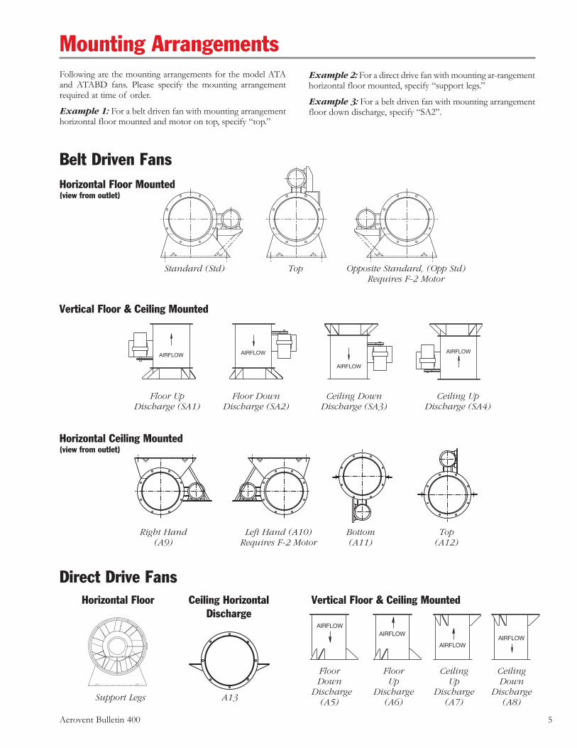
Mounting ArrangementsFollowing are the mounting arrangements for the model ATA and ATABD fans. Please specify the mounting arrangement required at time of order.
Example 1: For a belt driven fan with mounting arrangement horizontal floor mounted and motor on top, specify “top.”
Example 2: For a direct drive fan with mounting ar-rangement horizontal floor mounted, specify “support legs.”
Example 3: For a belt driven fan with mounting arrangement floor down discharge, specify “SA2”.
Direct Drive Fans
AIRFLOWAIRFLOW
AIRFLOWAIRFLOW
Vertical Floor & Ceiling Mounted
Horizontal Ceiling Mounted(view from outlet)
Vertical Floor & Ceiling MountedHorizontal Floor Ceiling HorizontalDischarge
Horizontal Floor Mounted(view from outlet)
Standard (Std) Top Opposite Standard, (Opp Std) Requires F-2 Motor
Floor Floor Ceiling Ceiling Down Up Up Down Discharge Discharge Discharge Discharge (A5) (A6) (A7) (A8)A13Support Legs
Right Hand Left Hand (A10) Bottom Top (A9) Requires F-2 Motor (A11) (A12)
AIRFLOW AIRFLOW
AIRFLOW
AIRFLOW
Floor Up Floor Down Ceiling Down Ceiling Up Discharge (SA1) Discharge (SA2) Discharge (SA3) Discharge (SA4)
Belt Driven Fans
6 Aerovent Bulletin 400
Present methods of testing fans provide accurate, dependable performance data; however, information available for designing systems is necessarily based on averages. Therefore, a certain amount of “rounding off ” of design figures is a reasonable approach and will produce a practical air handling system design. Most engineers prefer the static pressure or friction loss method of calculation. The fan is usually located somewhere within the system; therefore, it is only necessary to figure the entrance loss and the duct friction loss, then select the fan directly from the tables. This method assumes that the duct size from the outlet of the fan to where the air is released to atmosphere is essentially the same as the diameter of the fan.
• If the fan is at the beginning of the duct, then an inlet bell should be used and no entrance loss is calculated.
• If the fan is at the end of the duct, then the entrance loss and duct friction are calculated and this is the fan static pressure.
• If an outlet cone is used and there is a static regain, the regain can be added to the static pressure.
Some systems are designed using total pressure (TP). Using the following formulas, the total pressure can be calculated.
Fan Selection
Fan Selection Formulas
TP = VP + SP
x Density in lbs.per ft3
NOTE: This formula is used only for density at standard air, 0.075 lbs./ft3, 70°F and sea level.
NOTE: This formula is used when density is other than standard.
CFMVP = ~AREA x 1096.7!
2
CFMOV = ~AREA!
CFMVP = ~AREA x 4005!
2
Where: VP = Velocity pressure, IWG SP = Static pressure, IWG TP = Total pressure, IWG OV = Fan outlet velocity, FPM AREA = Fan outlet area, Ft2
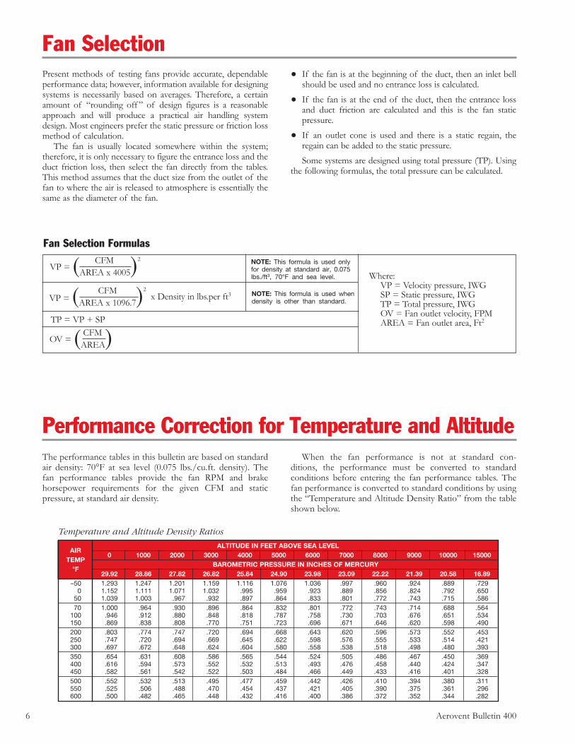
Performance Correction for Temperature and AltitudeThe performance tables in this bulletin are based on standard air density: 70°F at sea level (0.075 lbs./cu.ft. density). The fan performance tables provide the fan RPM and brake horsepower requirements for the given CFM and static pressure, at standard air density.
When the fan performance is not at standard con-ditions, the performance must be converted to standard conditions before entering the fan performance tables. The fan performance is converted to standard conditions by using the “Temperature and Altitude Density Ratio” from the table shown below.
Temperature and Altitude Density Ratios
ALTITUDE IN FEET ABOVE SEA LEVEL
AIR 0 1000 2000 3000 4000 5000 6000 7000 8000 9000 10000 15000
TEMP
BAROMETRIC PRESSURE IN INCHES OF MERCURY
°F 29.92 28.86 27.82 26.82 25.84 24.90 23.98 23.09 22.22 21.39 20.58 16.89
–50 1.293 1.247 1.201 1.159 1.116 1.076 1.036 .997 .960 .924 .889 .729 0 1.152 1.111 1.071 1.032 .995 .959 .923 .889 .856 .824 .792 .650 50 1.039 1.003 .967 .932 .897 .864 .833 .801 .772 .743 .715 .586 70 1.000 .964 .930 .896 .864 .832 .801 .772 .743 .714 .688 .564 100 .946 .912 .880 .848 .818 .787 .758 .730 .703 .676 .651 .534 150 .869 .838 .808 .770 .751 .723 .696 .671 .646 .620 .598 .490 200 .803 .774 .747 .720 .694 .668 .643 .620 .596 .573 .552 .453 250 .747 .720 .694 .669 .645 .622 .598 .576 .555 .533 .514 .421 300 .697 .672 .648 .624 .604 .580 .558 .538 .518 .498 .480 .393 350 .654 .631 .608 .586 .565 .544 .524 .505 .486 .467 .450 .369 400 .616 .594 .573 .552 .532 .513 .493 .476 .458 .440 .424 .347 450 .582 .561 .542 .522 .503 .484 .466 .449 .433 .416 .401 .328 500 .552 .532 .513 .495 .477 .459 .442 .426 .410 .394 .380 .311 550 .525 .506 .488 .470 .454 .437 .421 .405 .390 .375 .361 .296 600 .500 .482 .465 .448 .432 .416 .400 .386 .372 .352 .344 .282
Aerovent Bulletin 400 7
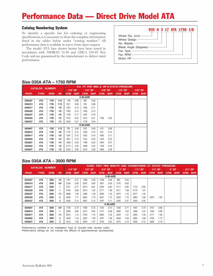
Performance Data — Direct Drive Model ATACatalog Numbering SystemTo identify a specific fan for ordering or engineering specifications, it is necessary to show the complete information listed in the tables below under “catalog number.” All performance data is available in curve form upon request. The model ATA fans shown herein have been tested in accordance with ASHRAE 51-85 and AMCA 210-85 Test Code and are guaranteed by the manufacturer to deliver rated performance.
035 A 3 17 ATA 1750 1/8
Wheel Dia. (cm)Wheel DesignNo. BladesBlade Angle (Degrees)Fan TypeFan RPMMotor HP
Size 035A ATA – 1750 RPM CU. FT. PER MIN. & HP @ STATIC PRESSURE
CATALOG NUMBER 1/8" SP 1/4" SP 3/8" SP 1/2" SP 5/8" SP
PROP TYPE RPM HP CFM BHP CFM BHP CFM BHP CFM BHP CFM BHP3-BLADE
035A307 ATA 1750 1/12 783 0.06 492 0.06 035A312 ATA 1750 1/12 1021 0.08 785 0.08 035A317 ATA 1750 1/8 1287 0.10 1056 0.11 035A322 ATA 1750 1/8 1505 0.13 1256 0.13 035A327 ATA 1750 1/6 1749 0.17 1487 0.18 035A332 ATA 1750 1/4 1912 0.22 1615 0.21 1190 0.20 035A337 ATA 1750 1/4 2049 0.27 1728 0.26
6-BLADE 035A607 ATA 1750 1/12 795 0.09 618 0.09 410 0.08 035A612 ATA 1750 1/8 1137 0.12 1000 0.13 670 0.12 035A617 ATA 1750 1/6 1397 0.15 1262 0.16 1085 0.17 035A622 ATA 1750 1/4 1661 0.19 1524 0.20 1353 0.22 035A627 ATA 1750 1/4 1939 0.25 1788 0.26 1604 0.27 035A632 ATA 1750 1/2 2174 0.30 1998 0.32 1783 0.32 035A637 ATA 1750 1/2 2423 0.39 2218 0.39 1960 0.39
Performance certified is for installation Type D: Ducted inlet, ducted outlet.Performance ratings do not include the effects of appurtenances (accessories).
Size 035A ATA – 3500 RPM CUBIC FEET PER MINUTE AND HORSEPOWER AT STATIC PRESSURE
CATALOG NUMBER 1/4" SP 1/2" SP 3/4" SP 1" SP 11⁄4" SP 11⁄2" SP 2" SP 21⁄2" SP
PROP TYPE RPM HP CFM BHP CFM BHP CFM BHP CFM BHP CFM BHP CFM BHP CFM BHP CFM BHP 3-BLADE
035A307 ATA 3500 1/2 1761 0.47 1566 0.48 1348 0.48 985 0.45 035A312 ATA 3500 3/4 2228 0.58 2042 0.60 1831 0.63 1570 0.63 035A317 ATA 3500 1 2751 0.77 2574 0.81 2355 0.84 2111 0.85 1773 0.85 035A322 ATA 3500 1 3194 0.99 3010 1.02 2771 1.06 2511 1.08 2175 1.07 035A327 ATA 3500 11⁄2 3688 1.36 3498 1.40 3263 1.42 2973 1.43 2617 1.40 035A332 ATA 3500 2 4046 1.71 3824 1.73 3547 1.73 3229 1.72 2864 1.68 2379 1.60 035A337 ATA 3500 2 4359 2.14 4097 2.13 3787 2.11 3456 2.07 3053 2.00
6-BLADE 035A607 ATA 3500 3/4 1729 0.73 1590 0.73 1425 0.73 1236 0.71 1047 0.70 819 0.66 035A612 ATA 3500 1 2390 0.90 2274 0.95 2147 0.99 2000 1.02 1806 1.04 1340 0.96 035A617 ATA 3500 11⁄2 2914 1.13 2794 1.19 2665 1.25 2523 1.31 2363 1.35 2171 1.38 035A622 ATA 3500 2 3450 1.43 3322 1.50 3187 1.56 3048 1.63 2894 1.68 2705 1.72 035A627 ATA 3500 2 4013 1.90 3878 1.97 3733 2.04 3575 2.10 3400 2.15 3208 2.18
8 Aerovent Bulletin 400
Performance certified is for installation Type D: Ducted inlet, ducted outlet.Performance ratings do not include the effects of appurtenances (accessories).
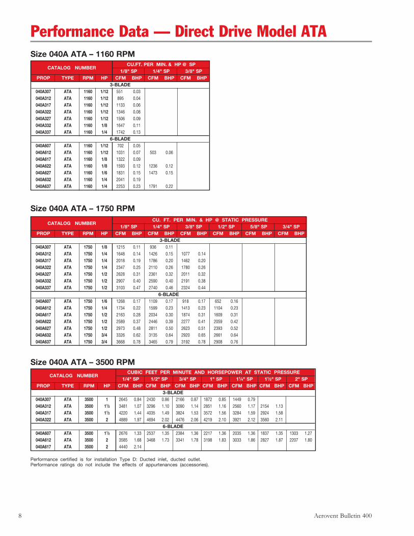
Size 040A ATA – 1160 RPM CU.FT. PER MIN. & HP @ SP
CATALOG NUMBER 1/8" SP 1/4" SP 3/8" SP
PROP TYPE RPM HP CFM BHP CFM BHP CFM BHP3-BLADE
040A307 ATA 1160 1/12 551 0.03 040A312 ATA 1160 1/12 895 0.04 040A317 ATA 1160 1/12 1133 0.06 040A322 ATA 1160 1/12 1346 0.08 040A327 ATA 1160 1/12 1506 0.09 040A332 ATA 1160 1/8 1647 0.11 040A337 ATA 1160 1/4 1742 0.13
6-BLADE 040A607 ATA 1160 1/12 702 0.05 040A612 ATA 1160 1/12 1031 0.07 503 0.06 040A617 ATA 1160 1/8 1322 0.09 040A622 ATA 1160 1/8 1593 0.12 1236 0.12 040A627 ATA 1160 1/6 1831 0.15 1473 0.15 040A632 ATA 1160 1/4 2041 0.19 040A637 ATA 1160 1/4 2253 0.23 1791 0.22
Size 040A ATA – 1750 RPM CU. FT. PER MIN. & HP @ STATIC PRESSURE
CATALOG NUMBER 1/8" SP 1/4" SP 3/8" SP 1/2" SP 5/8" SP 3/4" SP
PROP TYPE RPM HP CFM BHP CFM BHP CFM BHP CFM BHP CFM BHP CFM BHP 3-BLADE
040A307 ATA 1750 1/8 1215 0.11 936 0.11 040A312 ATA 1750 1/4 1648 0.14 1426 0.15 1077 0.14 040A317 ATA 1750 1/4 2018 0.19 1786 0.20 1462 0.20 040A322 ATA 1750 1/4 2347 0.25 2110 0.26 1780 0.26 040A327 ATA 1750 1/2 2628 0.31 2361 0.32 2011 0.32 040A332 ATA 1750 1/2 2907 0.40 2590 0.40 2191 0.38 040A337 ATA 1750 1/2 3103 0.47 2740 0.46 2324 0.44
6-BLADE 040A607 ATA 1750 1/6 1268 0.17 1109 0.17 918 0.17 652 0.16 040A612 ATA 1750 1/4 1734 0.22 1599 0.23 1413 0.23 1104 0.23 040A617 ATA 1750 1/2 2163 0.28 2034 0.30 1874 0.31 1609 0.31 040A622 ATA 1750 1/2 2589 0.37 2446 0.39 2277 0.41 2059 0.42 040A627 ATA 1750 1/2 2973 0.48 2811 0.50 2623 0.51 2393 0.52 040A632 ATA 1750 3/4 3326 0.62 3135 0.64 2920 0.65 2661 0.64 040A637 ATA 1750 3/4 3668 0.78 3465 0.79 3192 0.78 2908 0.76
Size 040A ATA – 3500 RPM CUBIC FEET PER MINUTE AND HORSEPOWER AT STATIC PRESSURE
CATALOG NUMBER 1/4" SP 1/2" SP 3/4" SP 1" SP 11⁄4" SP 11⁄2" SP 2" SP
PROP TYPE RPM HP CFM BHP CFM BHP CFM BHP CFM BHP CFM BHP CFM BHP CFM BHP3-BLADE
040A307 ATA 3500 1 2645 0.84 2430 0.86 2166 0.87 1872 0.85 1449 0.79 040A312 ATA 3500 11⁄2 3481 1.07 3296 1.10 3090 1.14 2851 1.16 2560 1.17 2154 1.13 040A317 ATA 3500 11⁄2 4220 1.44 4035 1.49 3824 1.53 3572 1.56 3284 1.59 2924 1.58 040A322 ATA 3500 2 4889 1.97 4694 2.02 4476 2.06 4219 2.10 3921 2.12 3560 2.11
6-BLADE 040A607 ATA 3500 11⁄2 2676 1.33 2537 1.35 2384 1.36 2217 1.36 2035 1.36 1837 1.35 1303 1.27 040A612 ATA 3500 2 3585 1.68 3468 1.73 3341 1.78 3198 1.83 3033 1.86 2827 1.87 2207 1.80 040A617 ATA 3500 2 4440 2.14
Performance Data — Direct Drive Model ATA
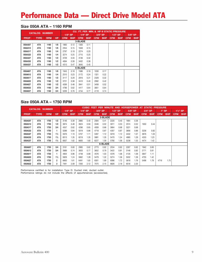
Aerovent Bulletin 400 9
Size 050A ATA – 1160 RPM
Size 050A ATA – 1750 RPM
CU. FT. PER MIN. & HP @ STATIC PRESSURE
CATALOG NUMBER 1/8" SP 1/4" SP 3/8" SP 1/2" SP 5/8" SP
PROP TYPE RPM HP CFM BHP CFM BHP CFM BHP CFM BHP CFM BHP3-BLADE
050A307 ATA 1160 1/8 1860 0.12 1300 0.11 050A312 ATA 1160 1/6 2354 0.15 1848 0.15 050A317 ATA 1160 1/4 2797 0.19 2274 0.20 050A322 ATA 1160 1/4 3274 0.25 2715 0.25 050A327 ATA 1160 1/2 3729 0.33 3136 0.32 050A332 ATA 1160 1/2 4064 0.39 3432 0.38 050A337 ATA 1160 1/2 4313 0.47 3645 0.45
6-BLADE 050A607 ATA 1160 1/6 1943 0.18 1586 0.18 1030 0.17 050A612 ATA 1160 1/4 2510 0.23 2172 0.24 1321 0.22 050A617 ATA 1160 1/2 3117 0.29 2816 0.31 2328 0.32 050A622 ATA 1160 1/2 3721 0.38 3410 0.40 2992 0.42 050A627 ATA 1160 1/2 4269 0.48 3941 0.51 3458 0.52 050A632 ATA 1160 3/4 4796 0.62 4417 0.64 3851 0.64 050A637 ATA 1160 3/4 5209 0.76 4744 0.77 4118 0.74
Performance certified is for installation Type D: Ducted inlet, ducted outlet.Performance ratings do not include the effects of appurtenances (accessories).
CUBIC FEET PER MINUTE AND HORSEPOWER AT STATIC PRESSURE
CATALOG NUMBER 1/8" SP 1/4" SP 3/8" SP 1/2" SP 5/8" SP 3/4" SP 1" SP 11⁄4" SP
PROP TYPE RPM HP CFM BHP CFM BHP CFM BHP CFM BHP CFM BHP CFM BHP CFM BHP CFM BHP 3-BLADE
050A307 ATA 1750 1/2 3146 0.39 2885 0.40 2584 0.41 2220 0.40 1664 0.36 050A312 ATA 1750 1/2 3874 0.48 3624 0.50 3346 0.52 3011 0.53 2574 0.52 1650 0.44 050A317 ATA 1750 3/4 4557 0.62 4296 0.65 4009 0.66 3664 0.68 3221 0.68 050A322 ATA 1750 1 5289 0.84 5019 0.86 4718 0.87 4357 0.87 3856 0.86 3236 0.82 050A327 ATA 1750 11⁄2 5976 1.10 5707 1.11 5397 1.12 5019 1.12 4432 1.07 3876 1.03 050A332 ATA 1750 11⁄2 6513 1.35 6219 1.35 5881 1.35 5470 1.34 4885 1.29 4333 1.23 050A337 ATA 1750 11⁄2 6937 1.62 6605 1.60 6227 1.59 5780 1.56 5238 1.53 4474 1.42
6-BLADE 050A607 ATA 1750 3/4 3161 0.60 2985 0.62 2773 0.62 2534 0.62 2267 0.62 1942 0.60 050A612 ATA 1750 3/4 3989 0.74 3833 0.77 3652 0.79 3422 0.81 3146 0.82 2771 0.81 050A617 ATA 1750 1 4904 0.96 4748 0.99 4576 1.03 4376 1.06 4135 1.09 3847 1.11 050A622 ATA 1750 11⁄2 5829 1.24 5662 1.28 5479 1.32 5274 1.36 5032 1.39 4755 1.42 050A627 ATA 1750 2 6663 1.61 6491 1.65 6301 1.69 6086 1.72 5818 1.76 5496 1.78 4716 1.75 050A632 ATA 1750 2 7491 2.09 7293 2.12 7075 2.15 6826 2.18 6516 2.20
Performance Data — Direct Drive Model ATA
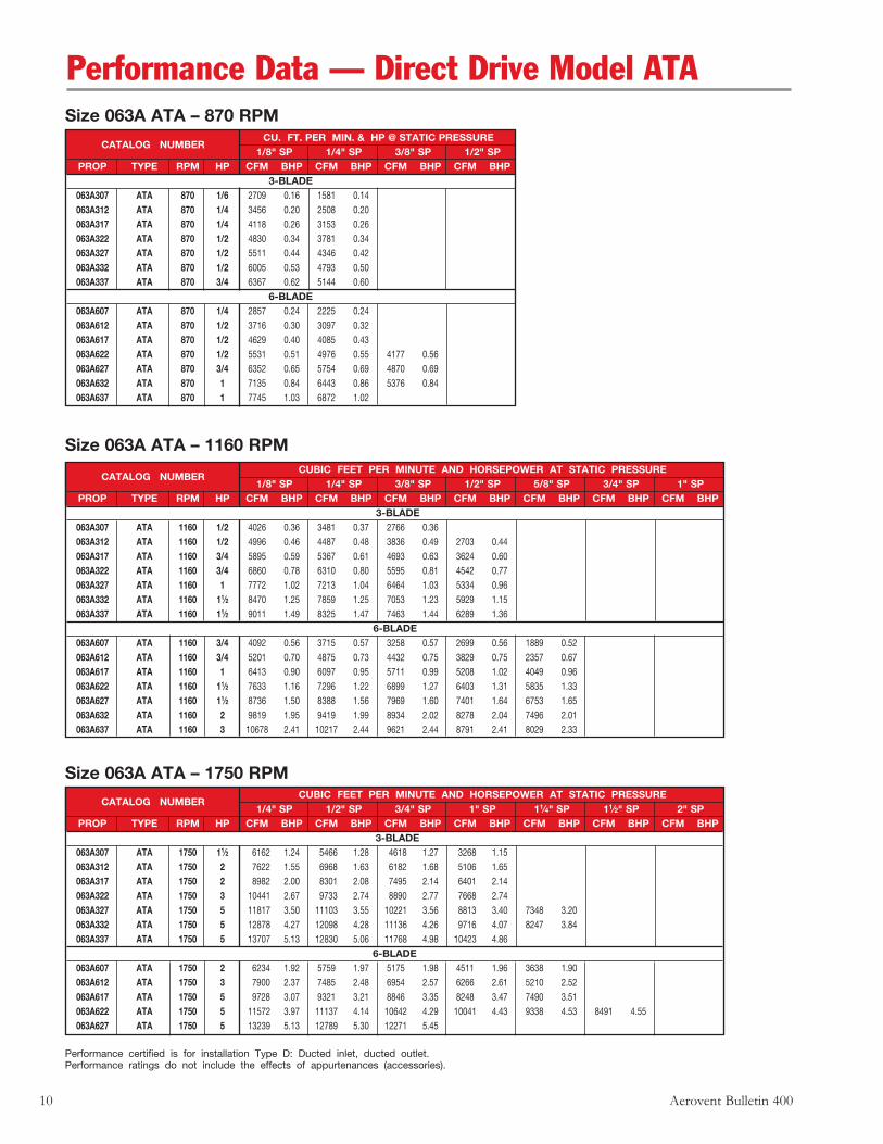
10 Aerovent Bulletin 400
Size 063A ATA – 870 RPM
Size 063A ATA – 1160 RPM
Size 063A ATA – 1750 RPM
CU. FT. PER MIN. & HP @ STATIC PRESSURE
CATALOG NUMBER 1/8" SP 1/4" SP 3/8" SP 1/2" SP
PROP TYPE RPM HP CFM BHP CFM BHP CFM BHP CFM BHP3-BLADE
063A307 ATA 870 1/6 2709 0.16 1581 0.14 063A312 ATA 870 1/4 3456 0.20 2508 0.20 063A317 ATA 870 1/4 4118 0.26 3153 0.26 063A322 ATA 870 1/2 4830 0.34 3781 0.34 063A327 ATA 870 1/2 5511 0.44 4346 0.42 063A332 ATA 870 1/2 6005 0.53 4793 0.50 063A337 ATA 870 3/4 6367 0.62 5144 0.60
6-BLADE 063A607 ATA 870 1/4 2857 0.24 2225 0.24 063A612 ATA 870 1/2 3716 0.30 3097 0.32 063A617 ATA 870 1/2 4629 0.40 4085 0.43 063A622 ATA 870 1/2 5531 0.51 4976 0.55 4177 0.56 063A627 ATA 870 3/4 6352 0.65 5754 0.69 4870 0.69 063A632 ATA 870 1 7135 0.84 6443 0.86 5376 0.84 063A637 ATA 870 1 7745 1.03 6872 1.02
CUBIC FEET PER MINUTE AND HORSEPOWER AT STATIC PRESSURE
CATALOG NUMBER 1/8" SP 1/4" SP 3/8" SP 1/2" SP 5/8" SP 3/4" SP 1" SP
PROP TYPE RPM HP CFM BHP CFM BHP CFM BHP CFM BHP CFM BHP CFM BHP CFM BHP 3-BLADE
063A307 ATA 1160 1/2 4026 0.36 3481 0.37 2766 0.36 063A312 ATA 1160 1/2 4996 0.46 4487 0.48 3836 0.49 2703 0.44 063A317 ATA 1160 3/4 5895 0.59 5367 0.61 4693 0.63 3624 0.60 063A322 ATA 1160 3/4 6860 0.78 6310 0.80 5595 0.81 4542 0.77 063A327 ATA 1160 1 7772 1.02 7213 1.04 6464 1.03 5334 0.96 063A332 ATA 1160 11⁄2 8470 1.25 7859 1.25 7053 1.23 5929 1.15 063A337 ATA 1160 11⁄2 9011 1.49 8325 1.47 7463 1.44 6289 1.36
6-BLADE 063A607 ATA 1160 3/4 4092 0.56 3715 0.57 3258 0.57 2699 0.56 1889 0.52 063A612 ATA 1160 3/4 5201 0.70 4875 0.73 4432 0.75 3829 0.75 2357 0.67 063A617 ATA 1160 1 6413 0.90 6097 0.95 5711 0.99 5208 1.02 4049 0.96 063A622 ATA 1160 11⁄2 7633 1.16 7296 1.22 6899 1.27 6403 1.31 5835 1.33 063A627 ATA 1160 11⁄2 8736 1.50 8388 1.56 7969 1.60 7401 1.64 6753 1.65 063A632 ATA 1160 2 9819 1.95 9419 1.99 8934 2.02 8278 2.04 7496 2.01 063A637 ATA 1160 3 10678 2.41 10217 2.44 9621 2.44 8791 2.41 8029 2.33
Performance certified is for installation Type D: Ducted inlet, ducted outlet.Performance ratings do not include the effects of appurtenances (accessories).
CUBIC FEET PER MINUTE AND HORSEPOWER AT STATIC PRESSURE
CATALOG NUMBER 1/4" SP 1/2" SP 3/4" SP 1" SP 11⁄4" SP 11⁄2" SP 2" SP
PROP TYPE RPM HP CFM BHP CFM BHP CFM BHP CFM BHP CFM BHP CFM BHP CFM BHP 3-BLADE
063A307 ATA 1750 11⁄2 6162 1.24 5466 1.28 4618 1.27 3268 1.15 063A312 ATA 1750 2 7622 1.55 6968 1.63 6182 1.68 5106 1.65 063A317 ATA 1750 2 8982 2.00 8301 2.08 7495 2.14 6401 2.14 063A322 ATA 1750 3 10441 2.67 9733 2.74 8890 2.77 7668 2.74 063A327 ATA 1750 5 11817 3.50 11103 3.55 10221 3.56 8813 3.40 7348 3.20 063A332 ATA 1750 5 12878 4.27 12098 4.28 11136 4.26 9716 4.07 8247 3.84 063A337 ATA 1750 5 13707 5.13 12830 5.06 11768 4.98 10423 4.86
6-BLADE 063A607 ATA 1750 2 6234 1.92 5759 1.97 5175 1.98 4511 1.96 3638 1.90 063A612 ATA 1750 3 7900 2.37 7485 2.48 6954 2.57 6266 2.61 5210 2.52 063A617 ATA 1750 5 9728 3.07 9321 3.21 8846 3.35 8248 3.47 7490 3.51 063A622 ATA 1750 5 11572 3.97 11137 4.14 10642 4.29 10041 4.43 9338 4.53 8491 4.55 063A627 ATA 1750 5 13239 5.13 12789 5.30 12271 5.45
Performance Data — Direct Drive Model ATA

Aerovent Bulletin 400 11
Size 071A ATA – 870 RPM CU. FT. PER MIN. & HP @ STATIC PRESSURE
CATALOG NUMBER 1/8" SP 1/4" SP 3/8" SP 1/2" SP 5/8" SP
PROP TYPE RPM HP CFM BHP CFM BHP CFM BHP CFM BHP CFM BHP3-BLADE
071A307 ATA 870 1/4 4102 0.28 3150 0.28 071A312 ATA 870 1/2 5154 0.36 4277 0.38 071A317 ATA 870 1/2 6110 0.46 5205 0.48 071A322 ATA 870 3/4 7139 0.61 6190 0.62 4579 0.58 071A327 ATA 870 3/4 8117 0.79 7132 0.79 5496 0.73 071A332 ATA 870 1 8845 0.96 7773 0.95 6147 0.87 071A337 ATA 870 11⁄2 9395 1.14 8214 1.11
6-BLADE 071A607 ATA 870 1/2 4245 0.44 3601 0.44 2752 0.43 071A612 ATA 870 3/4 5452 0.54 4864 0.58 3928 0.57 071A617 ATA 870 3/4 6754 0.71 6222 0.75 5464 0.78 071A622 ATA 870 1 8054 0.91 7499 0.96 6757 1.01 071A627 ATA 870 11⁄2 9234 1.17 8654 1.22 7809 1.26 6686 1.24 071A632 ATA 870 11⁄2 10375 1.51 9706 1.55 8729 1.56 7385 1.50 071A637 ATA 870 2 11274 1.86 10479 1.87 9277 1.84
Size 071A ATA – 1160 RPM CUBIC FEET PER MINUTE AND HORSEPOWER AT STATIC PRESSURE
CATALOG NUMBER 1/8" SP 1/4" SP 3/8" SP 1/2" SP 5/8" SP 3/4" SP 1" SP 11⁄4" SP
PROP TYPE RPM HP CFM BHP CFM BHP CFM BHP CFM BHP CFM BHP CFM BHP CFM BHP CFM BHP 3-BLADE
071A307 ATA 1160 3/4 5908 0.65 5333 0.68 4656 0.68 3758 0.65 071A312 ATA 1160 1 7291 0.82 6746 0.85 6118 0.88 5319 0.89 4054 0.82 071A317 ATA 1160 11⁄2 8584 1.05 8015 1.09 7371 1.13 6538 1.14 5382 1.10 071A322 ATA 1160 11⁄2 9970 1.41 9381 1.44 8705 1.46 7805 1.46 6612 1.41 071A327 ATA 1160 2 11275 1.85 10684 1.88 9982 1.89 9017 1.85 7726 1.75 071A332 ATA 1160 3 12287 2.26 11642 2.27 10872 2.26 9862 2.21 8572 2.10 071A337 ATA 1160 3 13083 2.72 12356 2.69 11501 2.65 10467 2.60 9120 2.49
6-BLADE 071A607 ATA 1160 1 5955 1.02 5567 1.04 5087 1.05 4557 1.04 3920 1.03 2994 0.97 071A612 ATA 1160 11⁄2 7531 1.25 7189 1.30 6772 1.34 6233 1.38 5594 1.37 3885 1.26 071A617 ATA 1160 2 9266 1.62 8927 1.69 8542 1.75 8077 1.81 7505 1.85 6720 1.84 071A622 ATA 1160 3 11018 2.09 10655 2.17 10250 2.25 9777 2.32 9212 2.37 8595 2.41 071A627 ATA 1160 3 12601 2.71 12225 2.79 11803 2.86 11298 2.93 10649 2.98 9933 3.00 071A632 ATA 1160 5 14164 3.52 13734 3.58 13248 3.64 12663 3.68 11912 3.70 11064 3.68 071A637 ATA 1160 5 15409 4.37 14918 4.41 14349 4.44 13605 4.44 12651 4.38 11828 4.29
Performance certified is for installation Type D: Ducted inlet, ducted outlet.Performance ratings do not include the effects of appurtenances (accessories).
Size 071A ATA – 1750 RPM CUBIC FEET PER MINUTE AND HORSEPOWER AT STATIC PRESSURE
CATALOG NUMBER 1/4" SP 1/2" SP 3/4" SP 1" SP 11⁄4" SP 11⁄2" SP 2" SP 21⁄2" SP 3" SP
PROP TYPE RPM HP CFM BHP CFM BHP CFM BHP CFM BHP CFM BHP CFM BHP CFM BHP CFM BHP CFM BHP3-BLADE
071A307 ATA 1750 3 9009 2.23 8269 2.30 7417 2.34 6391 2.30 4847 2.12 071A312 ATA 1750 3 11094 2.79 10385 2.91 9597 3.00 8651 3.05 7426 3.00 4979 2.59 071A317 ATA 1750 5 13048 3.60 12308 3.72 11494 3.83 10521 3.91 9272 3.90 071A322 ATA 1750 5 15142 4.82 14378 4.93 13525 5.01 12507 5.04 11097 4.99 9366 4.74 071A327 ATA 1750 71⁄2 17110 6.32 16346 6.42 15470 6.48 14403 6.45 12758 6.20 11171 5.95 071A332 ATA 1750 71⁄2 18646 7.76 17813 7.78 16855 7.78 15696 7.72 14054 7.44 12475 7.13 071A337 ATA 1750 10 19861 9.36 18920 9.25 17848 9.15 16586 9.03 15060 8.85 13022 8.29
6-BLADE 071A607 ATA 1750 5 9049 3.48 8551 3.55 7951 3.58 7275 3.59 6522 3.57 5609 3.49 071A612 ATA 1750 5 11420 4.27 10978 4.42 10465 4.56 9818 4.68 9038 4.74 7996 4.67 071A617 ATA 1750 71⁄2 14037 5.53 13597 5.73 13108 5.93 12544 6.12 11865 6.29 11054 6.38 071A622 ATA 1750 71⁄2 16686 7.15 16212 7.39 15694 7.62 15113 7.84 14429 8.04 13648 8.19 11352 8.13 071A627 ATA 1750 10 19074 9.27 18586 9.50 18048 9.73 17438 9.94 16684 10.14 15773 10.28 13597 10.12
Performance Data — Direct Drive Model ATA
12 Aerovent Bulletin 400
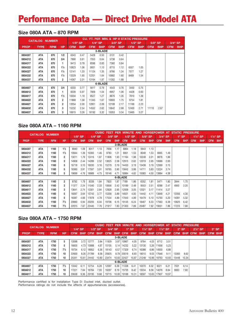
Performance certified is for installation Type D: Ducted inlet, ducted outlet.Performance ratings do not include the effects of appurtenances (accessories).
Size 080A ATA – 870 RPM CU. FT. PER MIN. & HP @ STATIC PRESSURE
CATALOG NUMBER 1/8" SP 1/4" SP 3/8" SP 1/2" SP 5/8" SP 3/4" SP
PROP TYPE RPM HP CFM BHP CFM BHP CFM BHP CFM BHP CFM BHP CFM BHP3-BLADE
080A307 ATA 870 1/2 6343 0.47 5428 0.50 3131 0.42 080A312 ATA 870 3/4 7890 0.61 7053 0.64 5738 0.64 080A317 ATA 870 1 9413 0.78 8596 0.83 7360 0.84 080A322 ATA 870 11⁄2 10823 1.06 9931 1.10 8715 1.12 6507 1.05 080A327 ATA 870 11⁄2 12141 1.33 11124 1.35 9766 1.34 7577 1.27 080A332 ATA 870 11⁄2 13329 1.65 12201 1.64 10682 1.60 8469 1.54 080A337 ATA 870 2 14367 2.01 13164 1.97 11302 1.88
6-BLADE 080A607 ATA 870 3/4 6333 0.77 5617 0.79 4543 0.76 3450 0.75 080A612 ATA 870 1 8339 0.97 7809 1.04 6957 1.06 4428 0.93 080A617 ATA 870 11⁄2 10034 1.19 9527 1.27 8876 1.35 7810 1.39 080A622 ATA 870 2 11868 1.58 11345 1.67 10693 1.75 9754 1.81 080A627 ATA 870 2 13554 2.00 12951 2.09 12199 2.17 11166 2.23 080A632 ATA 870 3 15232 2.54 14552 2.62 13642 2.68 12400 2.71 11110 2.67 080A637 ATA 870 3 16915 3.26 16192 3.32 15053 3.34 13465 3.27
Size 080A ATA – 1750 RPM CUBIC FEET PER MINUTE AND HORSEPOWER AT STATIC PRESSURE
CATALOG NUMBER 1/4" SP 1/2" SP 3/4" SP 1" SP 11⁄4" SP 11⁄2" SP 2" SP 21⁄2" SP 3" SP
PROP TYPE RPM HP CFM BHP CFM BHP CFM BHP CFM BHP CFM BHP CFM BHP CFM BHP CFM BHP CFM BHP3-BLADE
080A307 ATA 1750 5 13598 3.72 12777 3.84 11929 3.97 10967 4.05 9764 4.03 6712 3.51 080A312 ATA 1750 5 16605 4.73 15888 4.97 15105 5.14 14232 5.22 13130 5.26 11656 5.23 080A317 ATA 1750 71⁄2 19734 6.12 18952 6.36 18143 6.57 17329 6.74 16388 6.86 14930 6.88 080A322 ATA 1750 10 22600 8.35 21789 8.58 20925 8.78 20019 8.93 19010 9.03 17646 9.11 13393 8.62 080A327 ATA 1750 10 25341 10.61 24442 10.80 23474 10.93 22427 10.97 21248 10.96 19763 10.93 15448 10.34
6-BLADE 080A607 ATA 1750 71⁄2 13342 6.11 12754 6.28 12097 6.39 11338 6.41 10370 6.32 9221 6.21 7031 6.14 080A612 ATA 1750 10 17221 7.64 16784 7.93 16297 8.19 15735 8.42 15034 8.58 14076 8.64 9063 7.60 080A617 ATA 1750 10 20638 9.36 20195 9.68 19715 10.00 19188 10.31 18597 10.63 17907 10.97
Size 080A ATA – 1160 RPM CUBIC FEET PER MINUTE AND HORSEPOWER AT STATIC PRESSURE
CATALOG NUMBER 1/8" SP 1/4" SP 3/8" SP 1/2" SP 5/8" SP 3/4" SP 1" SP 11⁄4" SP 11⁄2" SP
PROP TYPE RPM HP CFM BHP CFM BHP CFM BHP CFM BHP CFM BHP CFM BHP CFM BHP CFM BHP CFM BHP3-BLADE
080A307 ATA 1160 11⁄2 8940 1.09 8317 1.13 7656 1.17 6864 1.18 5643 1.13 080A312 ATA 1160 11⁄2 10944 1.39 10393 1.46 9783 1.51 9061 1.53 8048 1.53 6665 1.49 080A317 ATA 1160 2 13011 1.79 12416 1.87 11806 1.93 11164 1.98 10248 2.01 8878 1.96 080A322 ATA 1160 3 14908 2.44 14289 2.52 13625 2.58 12915 2.62 12019 2.65 10686 2.65 080A327 ATA 1160 3 16718 3.10 16030 3.16 15279 3.19 14450 3.19 13438 3.19 12069 3.15 080A332 ATA 1160 5 18360 3.91 17597 3.91 16765 3.90 15842 3.88 14711 3.83 13224 3.74 080A337 ATA 1160 5 19699 4.76 18989 4.75 18146 4.71 16984 4.62 15583 4.50 13884 4.38
6-BLADE 080A607 ATA 1160 2 8792 1.79 8339 1.84 7820 1.87 7189 1.86 6352 1.81 5471 1.80 3944 1.75 080A612 ATA 1160 3 11377 2.24 11040 2.33 10656 2.42 10189 2.48 9553 2.51 8288 2.47 4950 2.20 080A617 ATA 1160 3 13641 2.74 13301 2.84 12928 2.95 12509 3.05 12021 3.17 11414 3.27 080A622 ATA 1160 5 16097 3.64 15743 3.77 15358 3.89 14931 4.00 14442 4.11 13848 4.21 12056 4.30 080A627 ATA 1160 5 18387 4.66 17978 4.78 17534 4.89 17043 4.99 16479 5.10 15793 5.20 14091 5.32 080A632 ATA 1160 71⁄2 20660 5.94 20205 6.04 19706 6.15 19145 6.24 18467 6.33 17563 6.39 15825 6.42 080A637 ATA 1160 71⁄2 22915 7.67 22445 7.76 21917 7.83 21303 7.89 20487 7.92 19051 7.86 17223 7.66
Performance Data — Direct Drive Model ATA
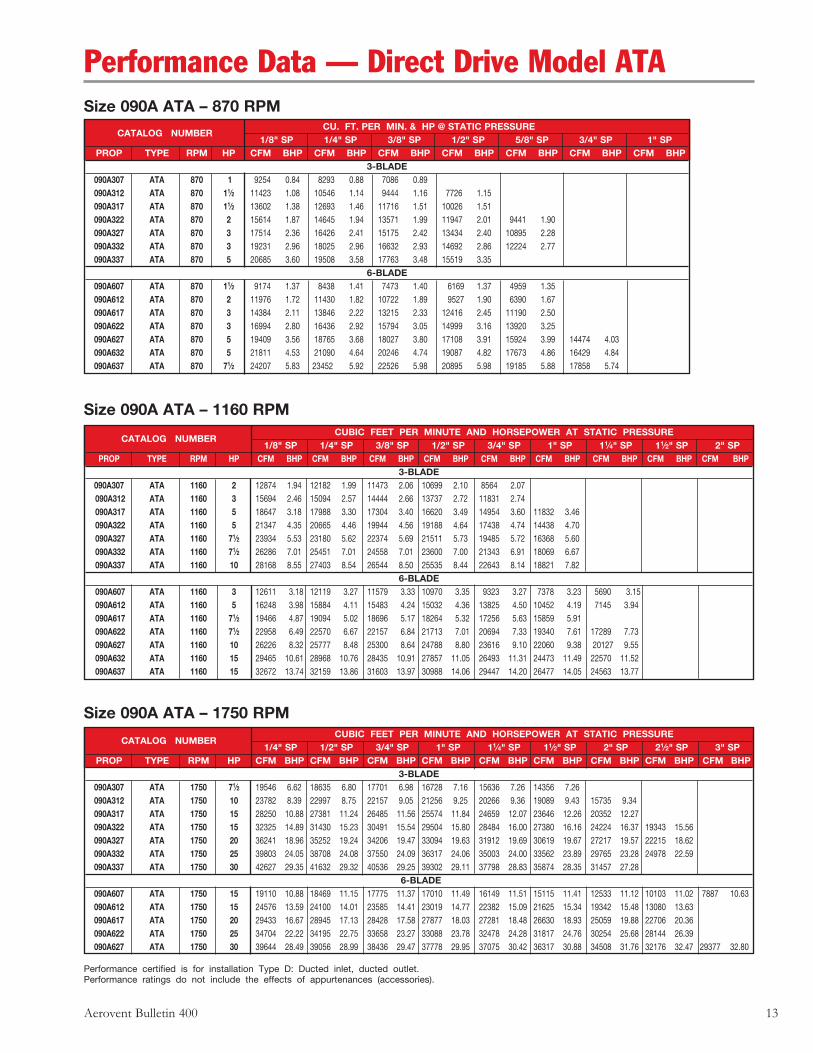
Aerovent Bulletin 400 13
Performance certified is for installation Type D: Ducted inlet, ducted outlet.Performance ratings do not include the effects of appurtenances (accessories).
Size 090A ATA – 870 RPM CU. FT. PER MIN. & HP @ STATIC PRESSURE
CATALOG NUMBER 1/8" SP 1/4" SP 3/8" SP 1/2" SP 5/8" SP 3/4" SP 1" SP
PROP TYPE RPM HP CFM BHP CFM BHP CFM BHP CFM BHP CFM BHP CFM BHP CFM BHP3-BLADE
090A307 ATA 870 1 9254 0.84 8293 0.88 7086 0.89 090A312 ATA 870 11⁄2 11423 1.08 10546 1.14 9444 1.16 7726 1.15 090A317 ATA 870 11⁄2 13602 1.38 12693 1.46 11716 1.51 10026 1.51 090A322 ATA 870 2 15614 1.87 14645 1.94 13571 1.99 11947 2.01 9441 1.90 090A327 ATA 870 3 17514 2.36 16426 2.41 15175 2.42 13434 2.40 10895 2.28 090A332 ATA 870 3 19231 2.96 18025 2.96 16632 2.93 14692 2.86 12224 2.77 090A337 ATA 870 5 20685 3.60 19508 3.58 17763 3.48 15519 3.35
6-BLADE 090A607 ATA 870 11⁄2 9174 1.37 8438 1.41 7473 1.40 6169 1.37 4959 1.35 090A612 ATA 870 2 11976 1.72 11430 1.82 10722 1.89 9527 1.90 6390 1.67 090A617 ATA 870 3 14384 2.11 13846 2.22 13215 2.33 12416 2.45 11190 2.50 090A622 ATA 870 3 16994 2.80 16436 2.92 15794 3.05 14999 3.16 13920 3.25 090A627 ATA 870 5 19409 3.56 18765 3.68 18027 3.80 17108 3.91 15924 3.99 14474 4.03 090A632 ATA 870 5 21811 4.53 21090 4.64 20246 4.74 19087 4.82 17673 4.86 16429 4.84 090A637 ATA 870 71⁄2 24207 5.83 23452 5.92 22526 5.98 20895 5.98 19185 5.88 17858 5.74
Size 090A ATA – 1750 RPM
Size 090A ATA – 1160 RPM CUBIC FEET PER MINUTE AND HORSEPOWER AT STATIC PRESSURE
CATALOG NUMBER 1/8" SP 1/4" SP 3/8" SP 1/2" SP 3/4" SP 1" SP 11⁄4" SP 11⁄2" SP 2" SP
PROP TYPE RPM HP CFM BHP CFM BHP CFM BHP CFM BHP CFM BHP CFM BHP CFM BHP CFM BHP CFM BHP3-BLADE
090A307 ATA 1160 2 12874 1.94 12182 1.99 11473 2.06 10699 2.10 8564 2.07 090A312 ATA 1160 3 15694 2.46 15094 2.57 14444 2.66 13737 2.72 11831 2.74 090A317 ATA 1160 5 18647 3.18 17988 3.30 17304 3.40 16620 3.49 14954 3.60 11832 3.46 090A322 ATA 1160 5 21347 4.35 20665 4.46 19944 4.56 19188 4.64 17438 4.74 14438 4.70 090A327 ATA 1160 71⁄2 23934 5.53 23180 5.62 22374 5.69 21511 5.73 19485 5.72 16368 5.60 090A332 ATA 1160 71⁄2 26286 7.01 25451 7.01 24558 7.01 23600 7.00 21343 6.91 18069 6.67 090A337 ATA 1160 10 28168 8.55 27403 8.54 26544 8.50 25535 8.44 22643 8.14 18821 7.82
6-BLADE 090A607 ATA 1160 3 12611 3.18 12119 3.27 11579 3.33 10970 3.35 9323 3.27 7378 3.23 5690 3.15 090A612 ATA 1160 5 16248 3.98 15884 4.11 15483 4.24 15032 4.36 13825 4.50 10452 4.19 7145 3.94 090A617 ATA 1160 71⁄2 19466 4.87 19094 5.02 18696 5.17 18264 5.32 17256 5.63 15859 5.91 090A622 ATA 1160 71⁄2 22958 6.49 22570 6.67 22157 6.84 21713 7.01 20694 7.33 19340 7.61 17289 7.73 090A627 ATA 1160 10 26226 8.32 25777 8.48 25300 8.64 24788 8.80 23616 9.10 22060 9.38 20127 9.55 090A632 ATA 1160 15 29465 10.61 28968 10.76 28435 10.91 27857 11.05 26493 11.31 24473 11.49 22570 11.52 090A637 ATA 1160 15 32672 13.74 32159 13.86 31603 13.97 30988 14.06 29447 14.20 26477 14.05 24563 13.77
CUBIC FEET PER MINUTE AND HORSEPOWER AT STATIC PRESSURE
CATALOG NUMBER 1/4" SP 1/2" SP 3/4" SP 1" SP 11⁄4" SP 11⁄2" SP 2" SP 21⁄2" SP 3" SP
PROP TYPE RPM HP CFM BHP CFM BHP CFM BHP CFM BHP CFM BHP CFM BHP CFM BHP CFM BHP CFM BHP3-BLADE
090A307 ATA 1750 71⁄2 19546 6.62 18635 6.80 17701 6.98 16728 7.16 15636 7.26 14356 7.26 090A312 ATA 1750 10 23782 8.39 22997 8.75 22157 9.05 21256 9.25 20266 9.36 19089 9.43 15735 9.34 090A317 ATA 1750 15 28250 10.88 27381 11.24 26485 11.56 25574 11.84 24659 12.07 23646 12.26 20352 12.27 090A322 ATA 1750 15 32325 14.89 31430 15.23 30491 15.54 29504 15.80 28484 16.00 27380 16.16 24224 16.37 19343 15.56 090A327 ATA 1750 20 36241 18.96 35252 19.24 34206 19.47 33094 19.63 31912 19.69 30619 19.67 27217 19.57 22215 18.62 090A332 ATA 1750 25 39803 24.05 38708 24.08 37550 24.09 36317 24.06 35003 24.00 33562 23.89 29765 23.28 24978 22.59 090A337 ATA 1750 30 42627 29.35 41632 29.32 40536 29.25 39302 29.11 37798 28.83 35874 28.35 31457 27.28
6-BLADE 090A607 ATA 1750 15 19110 10.88 18469 11.15 17775 11.37 17010 11.49 16149 11.51 15115 11.41 12533 11.12 10103 11.02 7887 10.63 090A612 ATA 1750 15 24576 13.59 24100 14.01 23585 14.41 23019 14.77 22382 15.09 21625 15.34 19342 15.48 13080 13.63 090A617 ATA 1750 20 29433 16.67 28945 17.13 28428 17.58 27877 18.03 27281 18.48 26630 18.93 25059 19.88 22706 20.36 090A622 ATA 1750 25 34704 22.22 34195 22.75 33658 23.27 33088 23.78 32478 24.28 31817 24.76 30254 25.68 28144 26.39 090A627 ATA 1750 30 39644 28.49 39056 28.99 38436 29.47 37778 29.95 37075 30.42 36317 30.88 34508 31.76 32176 32.47 29377 32.80
Performance Data — Direct Drive Model ATA
14 Aerovent Bulletin 400
Performance certified is for installation Type D: Ducted inlet, ducted outlet.Performance ratings do not include the effects of appurtenances (accessories).
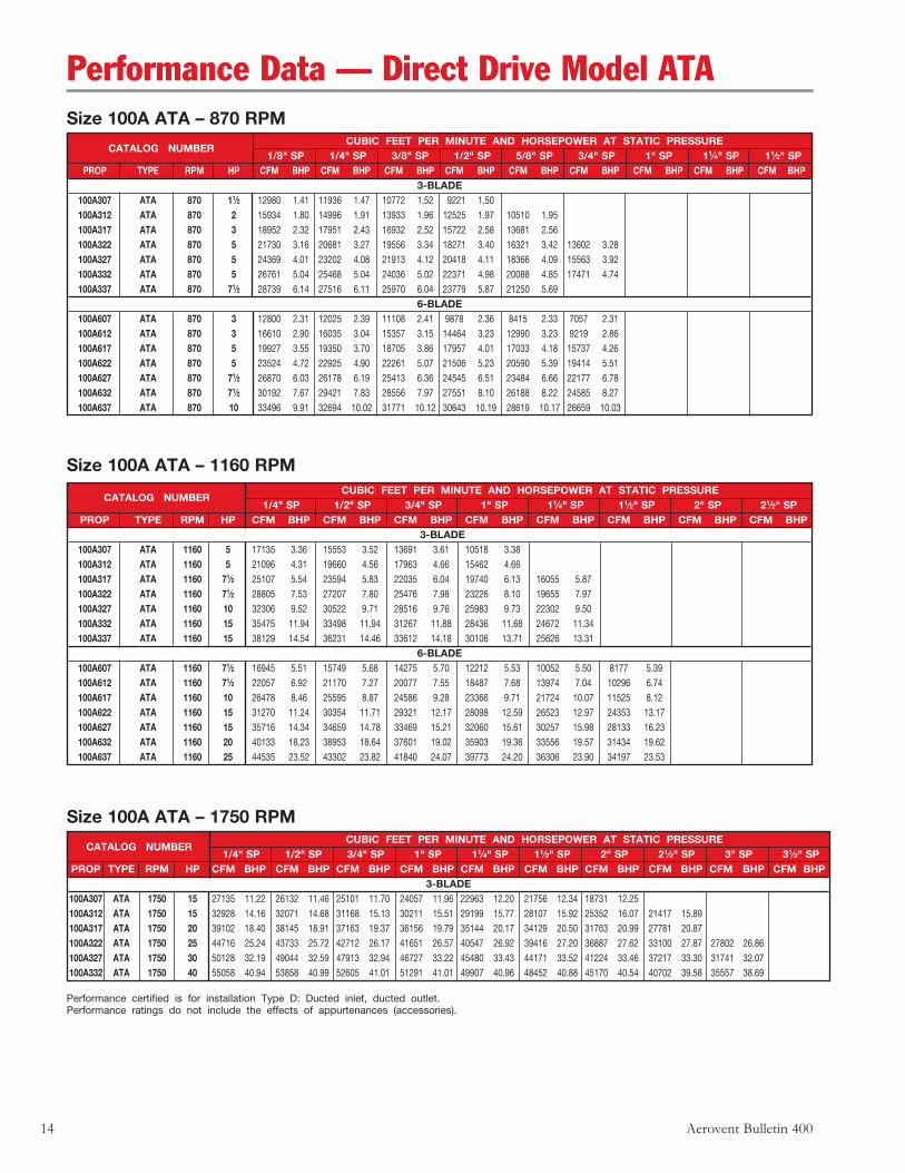
Size 100A ATA – 1750 RPM
Size 100A ATA – 870 RPM CUBIC FEET PER MINUTE AND HORSEPOWER AT STATIC PRESSURE
CATALOG NUMBER 1/8" SP 1/4" SP 3/8" SP 1/2" SP 5/8" SP 3/4" SP 1" SP 11⁄4" SP 11⁄2" SP
PROP TYPE RPM HP CFM BHP CFM BHP CFM BHP CFM BHP CFM BHP CFM BHP CFM BHP CFM BHP CFM BHP3-BLADE
100A307 ATA 870 11⁄2 12980 1.41 11936 1.47 10772 1.52 9221 1.50 100A312 ATA 870 2 15934 1.80 14996 1.91 13933 1.96 12525 1.97 10510 1.95 100A317 ATA 870 3 18952 2.32 17951 2.43 16932 2.52 15722 2.58 13681 2.56 100A322 ATA 870 5 21730 3.16 20681 3.27 19556 3.34 18271 3.40 16321 3.42 13602 3.28 100A327 ATA 870 5 24369 4.01 23202 4.08 21913 4.12 20418 4.11 18366 4.09 15563 3.92 100A332 ATA 870 5 26761 5.04 25468 5.04 24036 5.02 22371 4.98 20088 4.85 17471 4.74 100A337 ATA 870 71⁄2 28739 6.14 27516 6.11 25970 6.04 23779 5.87 21250 5.69
6-BLADE 100A607 ATA 870 3 12800 2.31 12025 2.39 11108 2.41 9878 2.36 8415 2.33 7057 2.31 100A612 ATA 870 3 16610 2.90 16035 3.04 15357 3.15 14464 3.23 12990 3.23 9219 2.86 100A617 ATA 870 5 19927 3.55 19350 3.70 18705 3.86 17957 4.01 17033 4.18 15737 4.26 100A622 ATA 870 5 23524 4.72 22925 4.90 22261 5.07 21506 5.23 20590 5.39 19414 5.51 100A627 ATA 870 71⁄2 26870 6.03 26178 6.19 25413 6.36 24545 6.51 23484 6.66 22177 6.78 100A632 ATA 870 71⁄2 30192 7.67 29421 7.83 28556 7.97 27551 8.10 26188 8.22 24585 8.27 100A637 ATA 870 10 33496 9.91 32694 10.02 31771 10.12 30643 10.19 28619 10.17 26659 10.03
Size 100A ATA – 1160 RPM CUBIC FEET PER MINUTE AND HORSEPOWER AT STATIC PRESSURE
CATALOG NUMBER 1/4" SP 1/2" SP 3/4" SP 1" SP 11⁄4" SP 11⁄2" SP 2" SP 21⁄2" SP
PROP TYPE RPM HP CFM BHP CFM BHP CFM BHP CFM BHP CFM BHP CFM BHP CFM BHP CFM BHP 3-BLADE
100A307 ATA 1160 5 17135 3.36 15553 3.52 13691 3.61 10518 3.38 100A312 ATA 1160 5 21096 4.31 19660 4.56 17963 4.66 15462 4.66 100A317 ATA 1160 71⁄2 25107 5.54 23594 5.83 22035 6.04 19740 6.13 16055 5.87 100A322 ATA 1160 71⁄2 28805 7.53 27207 7.80 25476 7.98 23226 8.10 19655 7.97 100A327 ATA 1160 10 32306 9.52 30522 9.71 28516 9.76 25983 9.73 22302 9.50 100A332 ATA 1160 15 35475 11.94 33498 11.94 31267 11.88 28436 11.68 24672 11.34 100A337 ATA 1160 15 38129 14.54 36231 14.46 33612 14.18 30106 13.71 25626 13.31
6-BLADE 100A607 ATA 1160 71⁄2 16945 5.51 15749 5.68 14275 5.70 12212 5.53 10052 5.50 8177 5.39 100A612 ATA 1160 71⁄2 22057 6.92 21170 7.27 20077 7.55 18487 7.68 13974 7.04 10296 6.74 100A617 ATA 1160 10 26478 8.46 25595 8.87 24586 9.28 23366 9.71 21724 10.07 11525 8.12 100A622 ATA 1160 15 31270 11.24 30354 11.71 29321 12.17 28098 12.59 26523 12.97 24353 13.17 100A627 ATA 1160 15 35716 14.34 34659 14.78 33469 15.21 32060 15.61 30257 15.98 28133 16.23 100A632 ATA 1160 20 40133 18.23 38953 18.64 37601 19.02 35903 19.36 33556 19.57 31434 19.62 100A637 ATA 1160 25 44535 23.52 43302 23.82 41840 24.07 39773 24.20 36306 23.90 34197 23.53
CUBIC FEET PER MINUTE AND HORSEPOWER AT STATIC PRESSURE
CATALOG NUMBER 1/4" SP 1/2" SP 3/4" SP 1" SP 11⁄4" SP 11⁄2" SP 2" SP 21⁄2" SP 3" SP 31⁄2" SP
PROP TYPE RPM HP CFM BHP CFM BHP CFM BHP CFM BHP CFM BHP CFM BHP CFM BHP CFM BHP CFM BHP CFM BHP3-BLADE
100A307 ATA 1750 15 27135 11.22 26132 11.46 25101 11.70 24057 11.96 22963 12.20 21756 12.34 18731 12.25 100A312 ATA 1750 15 32928 14.16 32071 14.68 31168 15.13 30211 15.51 29199 15.77 28107 15.92 25352 16.07 21417 15.89 100A317 ATA 1750 20 39102 18.40 38145 18.91 37163 19.37 36156 19.79 35144 20.17 34129 20.50 31763 20.99 27781 20.87 100A322 ATA 1750 25 44716 25.24 43733 25.72 42712 26.17 41651 26.57 40547 26.92 39416 27.20 36887 27.62 33100 27.87 27802 26.86 100A327 ATA 1750 30 50128 32.19 49044 32.59 47913 32.94 46727 33.22 45480 33.43 44171 33.52 41224 33.46 37217 33.30 31741 32.07 100A332 ATA 1750 40 55058 40.94 53858 40.99 52605 41.01 51291 41.01 49907 40.96 48452 40.88 45170 40.54 40702 39.58 35557 38.69
Performance Data — Direct Drive Model ATA

Aerovent Bulletin 400 15
Size 112A ATA – 870 RPM CUBIC FEET PER MINUTE AND HORSEPOWER AT STATIC PRESSURE
CATALOG NUMBER 1/8" SP 1/4" SP 3/8" SP 1/2" SP 5/8" SP 3/4" SP 1" SP 11⁄4" SP 11⁄2" SP
PROP TYPE RPM HP CFM BHP CFM BHP CFM BHP CFM BHP CFM BHP CFM BHP CFM BHP CFM BHP CFM BHP3-BLADE
112A307 ATA 870 3 18469 2.45 17313 2.53 16112 2.62 14732 2.67 12935 2.63 112A312 ATA 870 5 22568 3.12 21555 3.28 20445 3.39 19192 3.44 17561 3.46 15397 3.43 112A317 ATA 870 5 26823 4.03 25720 4.20 24581 4.33 23428 4.45 22037 4.53 19821 4.51 112A322 ATA 870 71⁄2 30722 5.50 29577 5.66 28356 5.79 27072 5.89 25608 5.95 23538 6.00 112A327 ATA 870 71⁄2 34449 6.99 33180 7.11 31808 7.20 30319 7.22 28617 7.21 26410 7.19 20151 6.72 112A332 ATA 870 10 37833 8.83 36427 8.84 24906 8.83 33250 8.80 31355 8.73 28884 8.57 112A337 ATA 870 10 40571 10.77 39271 10.74 37771 10.69 35845 10.54 33331 10.30 30546 10.04
6-BLADE 112A607 ATA 870 5 18132 4.03 17301 4.14 16366 4.21 15276 4.22 13851 4.14 12221 4.08 9209 4.03 112A612 ATA 870 71⁄2 23418 5.04 22801 5.23 22108 5.41 21301 5.56 20271 5.66 18806 5.69 11733 5.00 112A617 ATA 870 71⁄2 28068 6.17 27442 6.39 26762 6.60 26012 6.82 25162 7.04 24158 7.27 20902 7.41 112A622 ATA 870 10 33114 8.21 32461 8.46 31758 8.71 30990 8.95 30134 9.18 29134 9.40 26418 9.72 112A627 ATA 870 15 37826 10.51 37072 10.75 36260 10.98 35376 11.20 34392 11.42 33234 11.63 30294 11.96 112A632 ATA 870 15 42500 13.40 41662 13.62 40752 13.83 39747 14.03 38604 14.21 37134 14.38 33688 14.51 112A637 ATA 870 20 47134 17.33 46268 17.50 45312 17.65 44227 17.78 42938 17.88 40857 17.88 36604 17.51
Size 112A ATA – 1160 RPM CUBIC FEET PER MINUTE AND HORSEPOWER AT STATIC PRESSURE
CATALOG NUMBER 1/4" SP 1/2" SP 3/4" SP 1" SP 11⁄4" SP 11⁄2" SP 2" SP 21⁄2" SP 3" SP
PROP TYPE RPM HP CFM BHP CFM BHP CFM BHP CFM BHP CFM BHP CFM BHP CFM BHP CFM BHP CFM BHP3-BLADE
112A307 ATA 1160 71⁄2 24437 5.83 22694 6.06 20828 6.27 18570 6.32 14793 5.94 112A312 ATA 1160 71⁄2 29928 7.45 28382 7.86 26665 8.09 24600 8.20 21686 8.17 17421 7.91 112A317 ATA 1160 10 35583 9.61 33916 10.03 32209 10.38 30389 10.65 27680 10.75 23735 10.46 112A322 ATA 1160 15 40777 13.10 39039 13.50 37179 13.82 35171 14.04 32562 14.20 28710 14.12 112A327 ATA 1160 20 45727 16.61 43796 16.92 41687 17.10 39342 17.11 36425 17.07 32474 16.84 112A332 ATA 1160 20 50217 20.93 48078 20.95 45738 20.91 43127 20.79 39865 20.49 35658 19.98 112A337 ATA 1160 25 53889 25.52 51891 25.44 49502 25.24 46166 24.71 42207 24.05 37348 23.41
6-BLADE 112A607 ATA 1160 10 24044 9.58 22771 9.88 21306 10.01 19498 9.95 17126 9.70 14674 9.65 10433 9.30 112A612 ATA 1160 15 31125 11.99 30181 12.51 29096 12.97 27764 13.32 25915 13.47 21929 13.07 13098 11.73 112A617 ATA 1160 20 37323 14.69 36370 15.26 35320 15.84 34137 16.41 32744 17.03 30988 17.58 112A622 ATA 1160 25 44046 19.54 43054 20.21 41972 20.86 40767 21.49 39373 22.08 37667 22.63 32160 22.94 112A627 ATA 1160 30 50313 24.98 49166 25.61 47917 26.22 46532 26.81 44924 27.38 42958 27.91 38076 28.54 112A632 ATA 1160 40 56531 31.82 55256 32.40 53851 32.96 52265 33.48 50313 33.94 47721 34.28 42911 34.37 112A637 ATA 1160 40 62706 41.13 61385 41.57 59897 41.96 58155 42.28 55742 42.44 51679 42.05 46699 40.90
Performance Data — Direct Drive Model ATA
Performance certified is for installation Type D: Ducted inlet, ducted outlet.Performance ratings do not include the effects of appurtenances (accessories).
Size 112A ATA – 1750 RPM CUBIC FEET PER MINUTE AND HORSEPOWER AT STATIC PRESSURE
CATALOG NUMBER 1/4" SP 1/2" SP 3/4" SP 1" SP 11⁄4" SP 11⁄2" SP 2" SP 21⁄2" SP 3" SP 31⁄2" SP
PROP TYPE RPM HP CFM BHP CFM BHP CFM BHP CFM BHP CFM BHP CFM BHP CFM BHP CFM BHP CFM BHP CFM BHP3-BLADE
112A307 ATA 1750 20 38291 19.59 37177 19.93 36039 20.26 34879 20.61 33710 20.97 32497 21.31 29771 21.70 26274 21.49 16420 17.99 112A312 ATA 1750 30 46362 24.64 45417 25.39 44433 26.07 43406 26.68 42329 27.20 41204 27.58 38730 28.00 35544 28.18 31304 27.98 112A317 ATA 1750 40 55042 32.09 53979 32.81 52894 33.49 51788 34.12 50657 34.71 49523 35.25 47237 36.15 44521 36.81 40220 36.77 34740 35.60 112A322 ATA 1750 50 62912 44.10 61823 44.78 60703 45.43 59548 46.04 58356 46.59 57124 47.10 54578 47.87 51699 48.43 47690 48.86 42300 48.24
16 Aerovent Bulletin 400
Performance certified is for installation Type D: Ducted inlet, ducted outlet.Performance ratings do not include the effects of appurtenances (accessories).
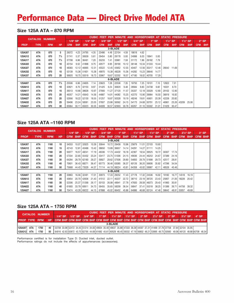
Size 125A ATA – 870 RPM CUBIC FEET PER MINUTE AND HORSEPOWER AT STATIC PRESSURE
CATALOG NUMBER 1/8" SP 1/4" SP 3/8" SP 1/2" SP 3/4" SP 1" SP 11⁄4" SP 11⁄2" SP 2" SP
PROP TYPE RPM HP CFM BHP CFM BHP CFM BHP CFM BHP CFM BHP CFM BHP CFM BHP CFM BHP CFM BHP3-BLADE
125A307 ATA 870 5 26072 4.23 24795 4.35 23486 4.48 22104 4.59 18618 4.62 125A312 ATA 870 71⁄2 31741 5.37 30639 5.61 29454 5.80 28178 5.93 24998 6.03 19941 5.93 125A317 ATA 870 71⁄2 37708 6.96 36491 7.20 35233 7.41 33961 7.59 31172 7.86 26182 7.79 125A322 ATA 870 10 43154 9.52 41898 9.75 40577 9.95 39190 10.12 36148 10.34 31333 10.44 125A327 ATA 870 15 48383 12.12 46995 12.31 45522 12.45 43952 12.55 40407 12.56 35317 12.46 28042 11.69 125A332 ATA 870 15 53139 15.36 51601 15.38 49970 15.38 48228 15.36 44282 15.23 38646 14.77 125A337 ATA 870 20 56920 18.75 55519 18.73 53967 18.67 52202 18.57 47180 18.02 40705 17.29
6-BLADE 125A607 ATA 870 71⁄2 25506 6.96 24605 7.14 23623 7.28 22536 7.35 19750 7.25 16101 7.10 12822 7.01 125A612 ATA 870 10 32821 8.70 32153 8.97 31425 9.24 30620 9.48 28584 9.83 24738 9.82 16331 8.70 125A617 ATA 870 15 39313 10.66 38628 10.97 37900 11.27 37120 11.57 35337 12.18 33028 12.80 29102 12.90 125A622 ATA 870 20 46357 14.21 45643 14.56 44887 14.91 44082 15.25 42270 15.90 39984 16.50 36819 16.92 125A627 ATA 870 20 52956 18.22 52130 18.55 51257 18.87 50328 19.19 48246 19.81 45601 20.39 42226 20.82 125A632 ATA 870 25 59496 23.24 58581 23.55 57607 23.86 56562 24.15 54173 24.68 50791 25.12 46961 25.26 43209 25.06 125A637 ATA 870 30 65964 30.11 65023 30.35 64009 30.57 62903 30.78 60267 31.10 55302 31.01 51029 30.47
CUBIC FEET PER MINUTE AND HORSEPOWER AT STATIC PRESSURE
CATALOG NUMBER 1/4" SP 1/2" SP 3/4" SP 1" SP 11⁄4" SP 11⁄2" SP 2" SP 21⁄2" SP 3" SP
PROP TYPE RPM HP CFM BHP CFM BHP CFM BHP CFM BHP CFM BHP CFM BHP CFM BHP CFM BHP CFM BHP3-BLADE
125A307 ATA 1160 10 34553 10.07 32625 10.39 30644 10.72 28458 10.96 25879 11.01 22103 10.60 125A312 ATA 1160 15 42143 12.81 40468 13.42 38650 13.89 36657 14.14 34291 14.27 31111 14.25 125A317 ATA 1160 20 50077 16.57 48241 17.19 46336 17.73 44432 18.18 42367 18.54 39525 18.72 30307 17.74 125A322 ATA 1160 25 57334 22.65 55432 23.24 53417 23.75 51306 24.15 49036 24.44 46253 24.67 37389 24.16 125A327 ATA 1160 30 64284 28.79 62180 29.27 59927 29.62 57506 29.80 54850 29.79 51698 29.73 42517 28.81 125A332 ATA 1160 40 70601 36.43 68271 36.47 65773 36.46 63085 36.37 60126 36.20 56606 35.82 47296 34.54 125A337 ATA 1160 50 75668 44.43 73529 44.37 71114 44.19 68224 43.81 64358 43.02 59987 42.11 48526 40.46
6-BLADE 125A607 ATA 1160 20 33863 16.56 32491 17.01 30973 17.33 29252 17.43 27178 17.32 24536 16.92 19182 16.77 14518 16.19 125A612 ATA 1160 25 43654 20.70 42636 21.43 41512 22.11 40237 22.72 38710 23.19 36725 23.43 25857 21.05 18228 20.42 125A617 ATA 1160 30 52306 25.37 51268 26.17 50153 26.98 48941 27.78 47600 28.58 46073 29.43 41960 30.81 125A622 ATA 1160 40 61693 33.79 60611 34.73 59455 35.65 58209 36.54 56847 37.41 55318 38.25 51389 39.71 44758 39.32 125A627 ATA 1160 50 70474 43.28 69222 44.15 67888 45.02 66452 45.86 64886 46.68 63124 47.48 58642 48.91 53057 49.69
Size 125A ATA –1160 RPM
Size 125A ATA – 1750 RPM CUBIC FEET PER MINUTE AND HORSEPOWER AT STATIC PRESSURE
CATALOG NUMBER 1/4" SP 1/2" SP 3/4" SP 1" SP 11⁄4" SP 11⁄2" SP 2" SP 21⁄2" SP 3" SP 31⁄2" SP 4" SP
PROP TYPE RPM HP CFM BHP CFM BHP CFM BHP CFM BHP CFM BHP CFM BHP CFM BHP CFM BHP CFM BHP CFM BHP CFM BHP3-BLADE
125A307 ATA 1750 40 53708 33.98 52472 34.45 51214 34.93 49934 35.40 48637 35.88 47333 36.39 44597 37.31 41499 37.79 37758 37.64 32104 35.95 125A312 ATA 1750 50 64916 42.63 63872 43.70 62795 44.69 61682 45.61 60529 46.45 59332 47.19 56802 48.21 53995 48.75 50560 49.06 46120 48.88 40708 48.34
Performance Data — Direct Drive Model ATA
Aerovent Bulletin 400 17
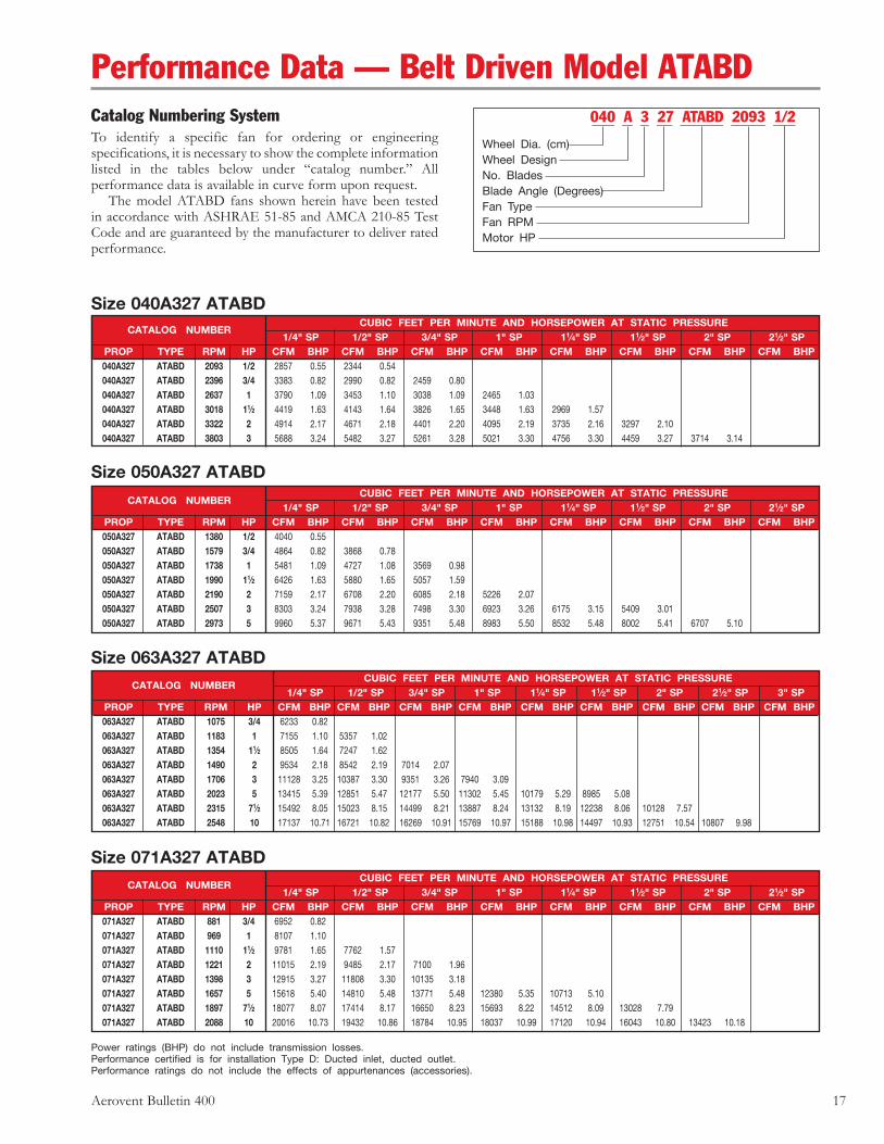
Performance Data — Belt Driven Model ATABDCatalog Numbering SystemTo identify a specific fan for ordering or engineering specifications, it is necessary to show the complete information listed in the tables below under “catalog number.” All performance data is available in curve form upon request. The model ATABD fans shown herein have been tested in accordance with ASHRAE 51-85 and AMCA 210-85 Test Code and are guaranteed by the manufacturer to deliver rated performance.
040 A 3 27 ATABD 2093 1/2
Wheel Dia. (cm)Wheel DesignNo. BladesBlade Angle (Degrees)Fan TypeFan RPMMotor HP
CUBIC FEET PER MINUTE AND HORSEPOWER AT STATIC PRESSURE
CATALOG NUMBER 1/4" SP 1/2" SP 3/4" SP 1" SP 11⁄4" SP 11⁄2" SP 2" SP 21⁄2" SP
PROP TYPE RPM HP CFM BHP CFM BHP CFM BHP CFM BHP CFM BHP CFM BHP CFM BHP CFM BHP 040A327 ATABD 2093 1/2 2857 0.55 2344 0.54 040A327 ATABD 2396 3/4 3383 0.82 2990 0.82 2459 0.80 040A327 ATABD 2637 1 3790 1.09 3453 1.10 3038 1.09 2465 1.03 040A327 ATABD 3018 11⁄2 4419 1.63 4143 1.64 3826 1.65 3448 1.63 2969 1.57 040A327 ATABD 3322 2 4914 2.17 4671 2.18 4401 2.20 4095 2.19 3735 2.16 3297 2.10 040A327 ATABD 3803 3 5688 3.24 5482 3.27 5261 3.28 5021 3.30 4756 3.30 4459 3.27 3714 3.14
CUBIC FEET PER MINUTE AND HORSEPOWER AT STATIC PRESSURE
CATALOG NUMBER 1/4" SP 1/2" SP 3/4" SP 1" SP 11⁄4" SP 11⁄2" SP 2" SP 21⁄2" SP
PROP TYPE RPM HP CFM BHP CFM BHP CFM BHP CFM BHP CFM BHP CFM BHP CFM BHP CFM BHP 050A327 ATABD 1380 1/2 4040 0.55 050A327 ATABD 1579 3/4 4864 0.82 3868 0.78 050A327 ATABD 1738 1 5481 1.09 4727 1.08 3569 0.98 050A327 ATABD 1990 11⁄2 6426 1.63 5880 1.65 5057 1.59 050A327 ATABD 2190 2 7159 2.17 6708 2.20 6085 2.18 5226 2.07 050A327 ATABD 2507 3 8303 3.24 7938 3.28 7498 3.30 6923 3.26 6175 3.15 5409 3.01 050A327 ATABD 2973 5 9960 5.37 9671 5.43 9351 5.48 8983 5.50 8532 5.48 8002 5.41 6707 5.10
Size 040A327 ATABD
Size 050A327 ATABD
Size 063A327 ATABD
Power ratings (BHP) do not include transmission losses.Performance certified is for installation Type D: Ducted inlet, ducted outlet.Performance ratings do not include the effects of appurtenances (accessories).
CUBIC FEET PER MINUTE AND HORSEPOWER AT STATIC PRESSURE
CATALOG NUMBER 1/4" SP 1/2" SP 3/4" SP 1" SP 11⁄4" SP 11⁄2" SP 2" SP 21⁄2" SP 3" SP
PROP TYPE RPM HP CFM BHP CFM BHP CFM BHP CFM BHP CFM BHP CFM BHP CFM BHP CFM BHP CFM BHP 063A327 ATABD 1075 3/4 6233 0.82 063A327 ATABD 1183 1 7155 1.10 5357 1.02 063A327 ATABD 1354 11⁄2 8505 1.64 7247 1.62 063A327 ATABD 1490 2 9534 2.18 8542 2.19 7014 2.07 063A327 ATABD 1706 3 11128 3.25 10387 3.30 9351 3.26 7940 3.09 063A327 ATABD 2023 5 13415 5.39 12851 5.47 12177 5.50 11302 5.45 10179 5.29 8985 5.08 063A327 ATABD 2315 71⁄2 15492 8.05 15023 8.15 14499 8.21 13887 8.24 13132 8.19 12238 8.06 10128 7.57 063A327 ATABD 2548 10 17137 10.71 16721 10.82 16269 10.91 15769 10.97 15188 10.98 14497 10.93 12751 10.54 10807 9.98
CUBIC FEET PER MINUTE AND HORSEPOWER AT STATIC PRESSURE
CATALOG NUMBER 1/4" SP 1/2" SP 3/4" SP 1" SP 11⁄4" SP 11⁄2" SP 2" SP 21⁄2" SP
PROP TYPE RPM HP CFM BHP CFM BHP CFM BHP CFM BHP CFM BHP CFM BHP CFM BHP CFM BHP 071A327 ATABD 881 3/4 6952 0.82 071A327 ATABD 969 1 8107 1.10 071A327 ATABD 1110 11⁄2 9781 1.65 7762 1.57 071A327 ATABD 1221 2 11015 2.19 9485 2.17 7100 1.96 071A327 ATABD 1398 3 12915 3.27 11808 3.30 10135 3.18 071A327 ATABD 1657 5 15618 5.40 14810 5.48 13771 5.48 12380 5.35 10713 5.10 071A327 ATABD 1897 71⁄2 18077 8.07 17414 8.17 16650 8.23 15693 8.22 14512 8.09 13028 7.79 071A327 ATABD 2088 10 20016 10.73 19432 10.86 18784 10.95 18037 10.99 17120 10.94 16043 10.80 13423 10.18
Size 071A327 ATABD
18 Aerovent Bulletin 400
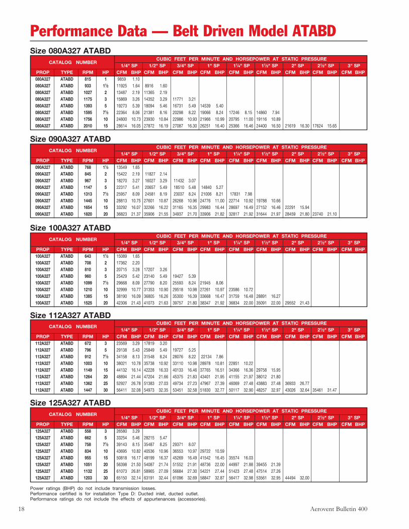
Size 080A327 ATABD CUBIC FEET PER MINUTE AND HORSEPOWER AT STATIC PRESSURE
CATALOG NUMBER 1/4" SP 1/2" SP 3/4" SP 1" SP 11⁄4" SP 11⁄2" SP 2" SP 21⁄2" SP 3" SP
PROP TYPE RPM HP CFM BHP CFM BHP CFM BHP CFM BHP CFM BHP CFM BHP CFM BHP CFM BHP CFM BHP 080A327 ATABD 815 1 9859 1.10 080A327 ATABD 933 11⁄2 11925 1.64 8916 1.60 080A327 ATABD 1027 2 13487 2.19 11365 2.19 080A327 ATABD 1175 3 15869 3.26 14352 3.29 11771 3.21 080A327 ATABD 1393 5 19273 5.39 18094 5.46 16731 5.49 14539 5.40 080A327 ATABD 1595 71⁄2 22364 8.06 21381 8.16 20298 8.22 19066 8.24 17246 8.15 14860 7.94 080A327 ATABD 1756 10 24800 10.73 23930 10.84 22986 10.93 21966 10.99 20795 11.00 19116 10.89 080A327 ATABD 2010 15 28614 16.05 27872 16.19 27087 16.30 26251 16.40 25366 16.46 24400 16.50 21619 16.30 17624 15.65
Size 090A327 ATABD CUBIC FEET PER MINUTE AND HORSEPOWER AT STATIC PRESSURE
CATALOG NUMBER 1/4" SP 1/2" SP 3/4" SP 1" SP 11⁄4" SP 11⁄2" SP 2" SP 21⁄2" SP 3" SP
PROP TYPE RPM HP CFM BHP CFM BHP CFM BHP CFM BHP CFM BHP CFM BHP CFM BHP CFM BHP CFM BHP 090A327 ATABD 768 11⁄2 13549 1.65 090A327 ATABD 845 2 15422 2.19 11827 2.14 090A327 ATABD 967 3 18270 3.27 16027 3.29 11432 3.07 090A327 ATABD 1147 5 22317 5.41 20657 5.49 18510 5.48 14840 5.27 090A327 ATABD 1313 71⁄2 25957 8.09 24581 8.19 23037 8.24 21006 8.21 17831 7.98 090A327 ATABD 1445 10 28813 10.75 27601 10.87 26268 10.96 24776 11.00 22714 10.92 19788 10.66 090A327 ATABD 1654 15 33292 16.07 32266 16.22 31165 16.35 29983 16.44 28697 16.49 27152 16.46 22291 15.94 090A327 ATABD 1820 20 36823 21.37 35906 21.55 34937 21.70 33906 21.82 32817 21.92 31644 21.97 28459 21.80 23740 21.10
Size 100A327 ATABD CUBIC FEET PER MINUTE AND HORSEPOWER AT STATIC PRESSURE
CATALOG NUMBER 1/4" SP 1/2" SP 3/4" SP 1" SP 11⁄4" SP 11⁄2" SP 2" SP 21⁄2" SP 3" SP
PROP TYPE RPM HP CFM BHP CFM BHP CFM BHP CFM BHP CFM BHP CFM BHP CFM BHP CFM BHP CFM BHP 100A327 ATABD 643 11⁄2 15089 1.65 100A327 ATABD 708 2 17362 2.20 100A327 ATABD 810 3 20715 3.28 17207 3.26 100A327 ATABD 960 5 25429 5.42 23140 5.49 19427 5.39 100A327 ATABD 1099 71⁄2 29668 8.09 27790 8.20 25593 8.24 21945 8.06 100A327 ATABD 1210 10 32999 10.77 31353 10.90 29518 10.98 27261 10.97 23586 10.72 100A327 ATABD 1385 15 38190 16.09 36805 16.26 35300 16.39 33668 16.47 31759 16.48 28891 16.27 100A327 ATABD 1525 20 42306 21.43 41073 21.63 39757 21.80 38347 21.92 36834 22.00 35091 22.00 29552 21.43
Size 112A327 ATABD CUBIC FEET PER MINUTE AND HORSEPOWER AT STATIC PRESSURE
CATALOG NUMBER 1/4" SP 1/2" SP 3/4" SP 1" SP 11⁄4" SP 11⁄2" SP 2" SP 21⁄2" SP 3" SP
PROP TYPE RPM HP CFM BHP CFM BHP CFM BHP CFM BHP CFM BHP CFM BHP CFM BHP CFM BHP CFM BHP 112A327 ATABD 672 3 23569 3.29 17819 3.20 112A327 ATABD 796 5 29138 5.43 25849 5.49 19727 5.25 112A327 ATABD 912 71⁄2 34158 8.13 31548 8.24 28076 8.22 22134 7.86 112A327 ATABD 1003 10 38021 10.78 35738 10.92 33110 10.98 28978 10.81 22851 10.22 112A327 ATABD 1149 15 44132 16.14 42228 16.33 40133 16.46 37765 16.51 34366 16.36 29758 15.95 112A327 ATABD 1264 20 48894 21.44 47204 21.66 45375 21.83 43401 21.95 41155 21.97 38012 21.80 112A327 ATABD 1362 25 52927 26.78 51383 27.03 49734 27.23 47967 27.39 46069 27.48 43883 27.48 36933 26.77 112A327 ATABD 1447 30 56411 32.08 54973 32.35 53451 32.58 51830 32.77 50117 32.90 48257 32.97 43026 32.64 35461 31.47
Size 125A327 ATABD CUBIC FEET PER MINUTE AND HORSEPOWER AT STATIC PRESSURE
CATALOG NUMBER 1/4" SP 1/2" SP 3/4" SP 1" SP 11⁄4" SP 11⁄2" SP 2" SP 21⁄2" SP 3" SP
PROP TYPE RPM HP CFM BHP CFM BHP CFM BHP CFM BHP CFM BHP CFM BHP CFM BHP CFM BHP CFM BHP 125A327 ATABD 558 3 26580 3.29 125A327 ATABD 662 5 33254 5.46 28215 5.47 125A327 ATABD 758 71⁄2 39143 8.15 35487 8.25 29371 8.07 125A327 ATABD 834 10 43695 10.82 40536 10.96 36553 10.97 29722 10.59 125A327 ATABD 955 15 50818 16.17 48199 16.37 45269 16.49 41542 16.45 35574 16.03 125A327 ATABD 1051 20 56398 21.50 54087 21.74 51552 21.91 48736 22.00 44997 21.88 39455 21.39 125A327 ATABD 1132 25 61073 26.81 58965 27.09 56684 27.30 54221 27.44 51423 27.48 47514 27.26 125A327 ATABD 1203 30 65150 32.14 63191 32.44 61096 32.69 58847 32.87 56417 32.98 53561 32.95 44494 32.00
Power ratings (BHP) do not include transmission losses.Performance certified is for installation Type D: Ducted inlet, ducted outlet.Performance ratings do not include the effects of appurtenances (accessories).
Performance Data — Belt Driven Model ATABD
Aerovent Bulletin 400 19
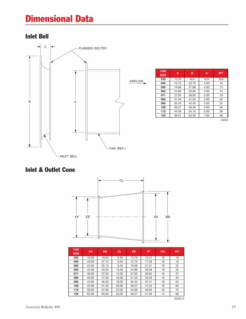
Inlet Bell
Inlet & Outlet Cone
C
B
FLANGES BOLTED
A
AIRFLOW
INLET BELL
FAN (REF.)
C
FAN SIZE
A B C WT.
035 13.78 N/A N/A N/A 040 15.75 23.75 4.00 10 050 19.68 27.68 4.00 13 063 24.80 32.80 4.00 14 071 27.95 38.00 5.00 19 080 31.50 41.50 5.00 20 090 35.43 45.40 5.00 24 100 39.37 49.40 5.00 28 112 44.09 54.10 5.00 38 125 49.21 63.20 7.00 48
FF EE
CL
AA BB
FAN SIZE
AA BB CL EE FF GA. WT.
035 18.00 18.63 8.50 13.78 15.31 18 16 040 20.00 21.13 8.50 15.75 17.38 18 19 050 24.00 25.13 8.50 19.68 21.31 18 22 063 32.00 33.50 13.00 24.80 26.68 18 32 071 36.00 37.50 14.00 27.95 29.85 18 37 080 40.00 41.50 16.00 31.50 33.38 18 45 090 44.00 45.50 18.00 35.43 37.31 18 53 100 50.00 51.50 20.00 39.37 41.25 16 63 112 56.00 57.50 22.00 44.09 46.00 16 75 125 62.00 63.50 25.00 49.21 51.09 14 90
Dimensional Data
32253-A
32254
20 Aerovent Bulletin 400
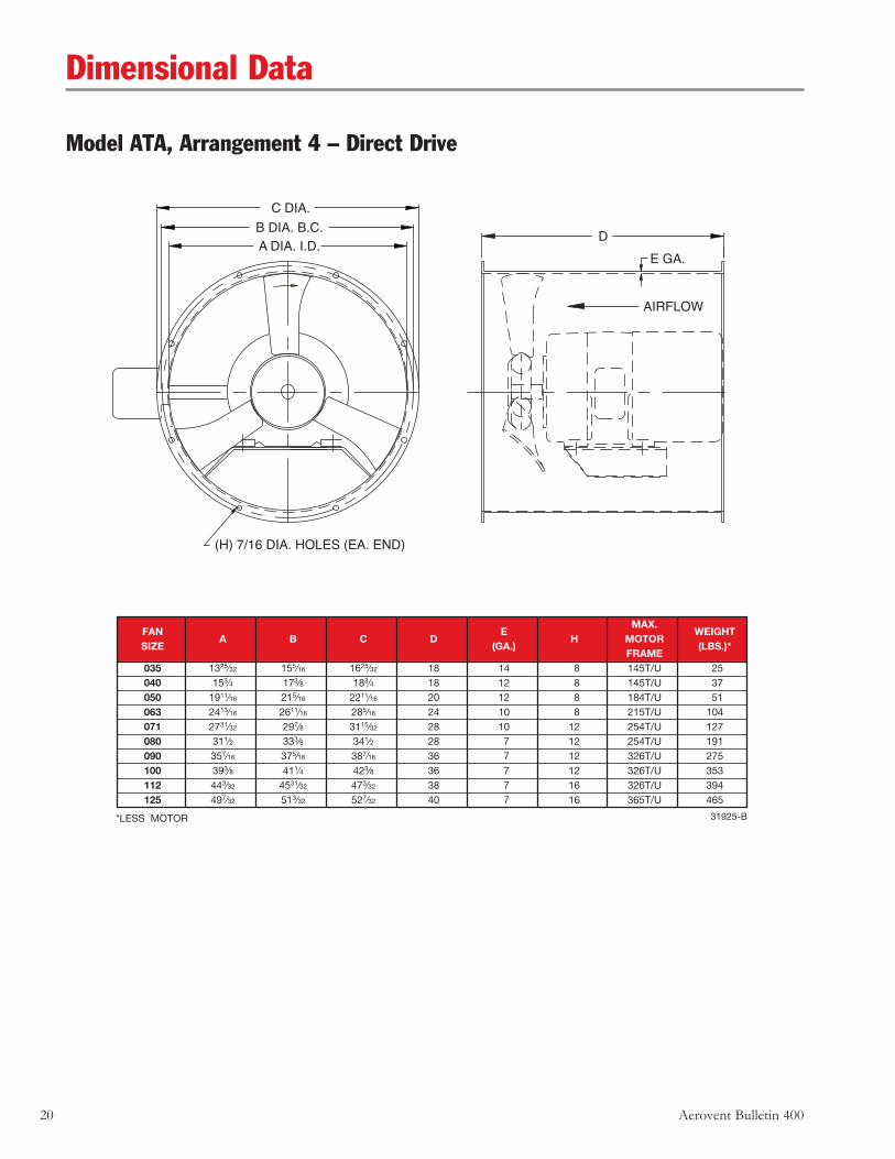
*LESS MOTOR
Model ATA, Arrangement 4 – Direct Drive
C DIA.
B DIA. B.C.A DIA. I.D.
(H) 7/16 DIA. HOLES (EA. END)
D
E GA.
AIRFLOW
Dimensional Data
FAN
E MAX.
WEIGHT SIZE
A B C D (GA.)
H MOTOR (LBS.)*
FRAME 035 1325⁄32 155⁄16 1625⁄32 18 14 8 145T/U 25 040 153⁄4 173⁄8 183⁄4 18 12 8 145T/U 37 050 1911⁄16 215⁄16 2211⁄16 20 12 8 184T/U 51 063 2413⁄16 2611⁄16 285⁄16 24 10 8 215T/U 104 071 2731⁄32 297⁄8 3115⁄32 28 10 12 254T/U 127 080 311⁄2 333⁄8 341⁄2 28 7 12 254T/U 191 090 357⁄16 375⁄16 387⁄16 36 7 12 326T/U 275 100 393⁄8 411⁄4 423⁄8 36 7 12 326T/U 353 112 443⁄32 4531⁄32 473⁄32 38 7 16 326T/U 394 125 497⁄32 513⁄32 527⁄32 40 7 16 365T/U 465
31925-B
Aerovent Bulletin 400 21
Typical SpecificationsModel ATA, Arrangement 4 – Direct DriveFans, where indicated on drawings and schedules, shall be Model ATA, Arrangement 4, direct drive, axial flow type with fan blades being capable of individual manual pitch adjustment while the fan is stopped. Fans shall be as manufactured by Aerovent, Minneapolis, Minnesota, and shall be of the size and capacity as indicated in the fan schedules. Model ATA fans shall be tested in an AMCA registered laboratory in accordance with AMCA 210 and AMCA 300 test codes and are licensed to bear the AMCA certified ratings seal for both Air and Sound. In addition each unit shall be factory run tested and final trim balanced prior to shipment.
CONSTRUCTION — Fan casings shall be welded of ASTM A-569 low carbon, commercial quality 14-gauge hot rolled steel in sizes through 14" diameter, 12-gauge hot rolled steel in sizes through 20" diameter, 10-gauge hot rolled steel from 24" diameter through 28" diameter, and 7-gauge hot rolled steel on sizes above 30" in diameter. Inlet and outlet flanges shall be integrally rolled mechanically from fan casing sheet steel to insure concentricity and alignment. Accuracy and uniformity of the fan casing shall be insured through the use of welding jigs and fixtures. A fabricated steel motor support base of minimum 3∕16" thick plate steel shall be welded into the inlet end of the fan casing.
PROPELLERS — Fan blades shall be permanent mold A319 aluminum precision alloy castings. Fan center hub boss shall be cast iron bolted to stamped steel hub halves coated by electrodeposition. Blade tip clearance shall be within tolerance to meet certified performance. Fan blade pitch angle shall be individually manually adjustable when fan is stopped. The fan propeller shall be secured directly to the motor shaft with knurled cup point set screws in all sizes to 20" diameter and split taper lock bushings in all larger sizes. The motor and propeller assembly shall be enclosed entirely within the fan casing.
BALANCING — The fan propeller assembly shall be statically and dynamically balanced in accordance with ANSI/AMCA 204-96 “Balance Quality and Vibration Levels for Fans” to Fan Application Category BV-3, Balance Quality Grade G6.3. In addition, direct drive fan propellers shall be balanced on the motor shaft after final assembly in the fan casing, in the manufacturing facility to the following peak velocity values, filter-in, at the fan test speed:
Fan Application Category Rigidly Mounted (In/Sec) Flexibly Mounted (In/Sec) BV-3 0.15 0.20
Final test room vibration levels in the axial, vertical, and horizontal planes shall be recorded and a written copy shall be available upon request.
MOTORS — Fan motors shall be manufactured in accordance with current applicable standards of IEEE and NEMA. They shall be foot-mounted, NEMA standard, open drip-proof (ODP), continuous duty, ball bearing with class “B” insulation. External grease fittings with extended grease leads shall be supplied for lubrication of the motor bearings on all motors that provide grease fittings. Motor bearings shall have a minimum L-10 life as defined by AFBMA of at least 40,000 hours (200,000 hours average life).
FINISH — The units, after fabrication, shall be cleaned and chemically pretreated by a phosphatizing process and shall be painted inside and out with two coats of air dry enamel. The fan shall be coated with the following optional finishes: M Carbocoat 30 (Replaces Sanitile 550) M Hot Dip Galvanizing M Plasite 4310 – Vinyl Ester M Plasite 9500 (Replaces Plasite 1246) M Plasite 7122L – Air Dry Epoxy Phenolic M Plasite 3070 (Replaces Plasite 3066) M Heresite VR506 – Air Dry Phenolic M Dupont ASA – 70 Gray – Polyester (Replaces Farboil)
SOUND POWER LEVELS — The sound power level of the fans shall not exceed: Octave Band - CPS (Sound Power 10-12)
63 125 250 500 1000 2000 4000 8000
22 Aerovent Bulletin 400
7/16 DIA. "G" HOLES
AIRFLOW
D
E GA. A DIA. I.D.B DIA. B.C.C DIA. O.D.
MIN.MAX.
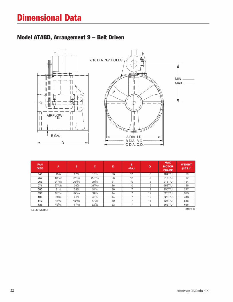
Dimensional Data
Model ATABD, Arrangement 9 – Belt Driven
*LESS MOTOR
FAN
E MAX.
WEIGHT SIZE
A B C D (GA.)
G MOTOR (LBS.)*
FRAME 040 153⁄4 173⁄8 183⁄4 26 12 8 184T/U 69 050 1911⁄16 215⁄16 2211⁄16 26 12 8 215T/U 82 063 2413⁄16 2611⁄16 285⁄16 31 10 8 215T/U 134 071 2731⁄32 297⁄8 3115⁄32 36 10 12 256T/U 165 080 311⁄2 333⁄8 341⁄2 36 7 12 256T/U 277 090 357⁄16 375⁄16 387⁄16 44 7 12 326T/U 373 100 393⁄8 411⁄4 423⁄8 44 7 12 326T/U 418 112 443⁄32 4531⁄32 477⁄32 50 7 16 326T/U 516 125 497⁄32 513⁄32 527⁄32 52 7 16 365T/U 638
31928-D
Aerovent Bulletin 400 23
Typical SpecificationsModel ATABD, Arrangement 9 – Belt DrivenFans, where indicated on drawings and schedules, shall be Model ATABD, Arrangement 9, V-belt driven, axial flow type with fan blades capable of individual manual pitch adjustment while the fan is stopped. Fans shall be as manufactured by Aerovent, Minneapolis, Minnesota, and shall be of the size and capacity as indicated in the fan schedules. Model ATABD fans have been tested in an AMCA registered laboratory in accordance with AMCA 210 and AMCA 300 test codes and are licensed to bear the AMCA certified ratings seal for both Air and Sound. In addition each unit shall be factory run tested and final trim balanced prior to shipment.
CONSTRUCTION — Fan casings shall be welded of ASTM A-569 low carbon, commercial quality 12-gauge hot rolled steel in sizes through 20" diameter, 10-gauge hot rolled steel from 24" diameter through 28" diameter, and 7-gauge hot rolled steel on sizes greater than 30" in diameter. Inlet and outlet flanges shall be integrally rolled mechanically from fan casing sheet steel to insure concentricity and alignment. Accuracy and uniformity of the fan casing shall be insured through the use of welding jigs and fixtures. The motor base plate shall be fabricated of minimum 3∕16" steel plate and welded to the exterior of the fan casing. The adjustment of belt tension shall be accomplished with an adjustable slide rail base.
PROPELLERS — Fan blades shall be permanent mold A319 aluminum alloy precision castings. Fan center hub boss shall be cast iron bolted to stamped steel hub halves coated by electrodeposition. Blade tip clearance shall be within tolerance to meet certified performance. Fan blade pitch angle shall be individually manually adjustable when fan is stopped. The fan propeller shall be secured to the fan shaft with knurled cup point set screws in all sizes to 20" diameter and split taper lock bushings in all larger sizes.
SHAFT & BEARINGS — All fans shall be supplied with a shaft of AISI C-1045 steel material that has been properly turned, ground, and polished for accuracy. The shaft shall be supported by a matched pair of sealed pillow block bearings. Grease leads are to be extended from the fan shaft bearings to zerk fittings mounted on the exterior of the fan casing to facilitate bearing relubrication without the need to gain service access inside the ductwork or the fan casing. All fan bearings are to have an L-10 minimum life as defined by AFBMA of at least 20,000 hours. This L-10 minimum life converts to an average bearing life in excess of 100,000 hours.
DRIVES — Fan drives shall include cast iron sheaves and non-static conducting belts. Fans equipped with motors up to and including five horsepower will be furnished with a variable pitch type drive sheave to allow for minor speed adjustment of the fan propeller during system balance. Fans equipped with larger motors will be furnished with a fixed drive sheave. A belt guard or an optional motor cover is to be provided with all belt driven fans to afford personnel safety and general traffic protection.
MOTORS — Fan motors shall be manufactured in accordance with current applicable standards of IEEE and NEMA. They shall be foot-mounted, NEMA standard, open drip-proof (ODP), continuous duty, ball bearing with class “B” insulation.
BALANCING — The propeller assembly shall be statically and dynamically balanced in accordance with ANSI/AMCA 204-96 “Balance Quality and Vibration Levels for Fans” to Fan Application Category BV-3, Balance Quality Grade G6.3. In addition, belt driven fan propellers shall be balanced on the fan shaft after final assembly in the fan casing, in the manufacturing facility to the following peak velocity values, filter-in, at the fan test speed:
Fan Application Category Rigidly Mounted (In/Sec) Flexibly Mounted (In/Sec) BV-3 0.15 0.20
Final test room vibration levels in the axial, vertical, and horizontal planes shall be recorded and a written copy shall be available upon request.
FINISH — The units, after fabrication, shall be cleaned and chemically pretreated by a phosphatizing process and shall be painted inside and out with two coats of air dry enamel. The fan shall be coated with the following optional finishes: M Carbocoat 30 (Replaces Sanitile 550) M Hot Dip Galvanizing M Plasite 4310 – Vinyl Ester M Plasite 9500 (Replaces Plasite 1246) M Plasite 7122L – Air Dry Epoxy Phenolic M Plasite 3070 (Replaces Plasite 3066) M Heresite VR506 – Air Dry Phenolic M Dupont ASA – 70 Gray – Polyester (Replaces Farboil)
SOUND POWER LEVELS — The sound power level of the fans shall not exceed: Octave Band - CPS (Sound Power 10–12 watts)
63 125 250 500 1000 2000 4000 8000


