POROSITY DETERMINATION FROM LOGS des in this section are modified primarily from NExT PERF Short Course Note many of the NExT slides appears to have been obtained from other primary that are not cited. Some slides have a notes section.
Transcript
POROSITY DETERMINATIONFROM LOGS
Most slides in this section are modified primarily from NExT PERF Short Course Notes, 1999.However, many of the NExT slides appears to have been obtained from other primarysources that are not cited. Some slides have a notes section.
Well LogSP Resistivity
OPENHOLE LOG EVALUATION
Oil sand
Gammaray
Resisitivity Porosity
Increasingradioactivity
Increasingresistivity
Increasingporosity
Shale
Shale
POROSITY DETERMINATION BY LOGGING
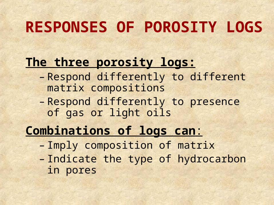
POROSITY LOG TYPES
3 Main Log Types
• Bulk density
• Sonic (acoustic)
• Compensated neutron
These logs do not measures porosity directly. To accurately calculate porosity, the analyst must know:•Formation lithology • Fluid in pores of sampled reservoir volume
DENSITY LOGS• Uses radioactive source to generate gamma
rays
• Gamma ray collides with electrons in formation, losing energy
• Detector measures intensity of back-scattered gamma rays, which is related to electron density of the formation
• Electron density is a measure of bulk density
DENSITY LOGS
• Bulk density, b, is dependent upon:
– Lithology
– Porosity
– Density and saturation of fluids in pores
• Saturation is fraction of pore volume occupied by a particular fluid (intensive)
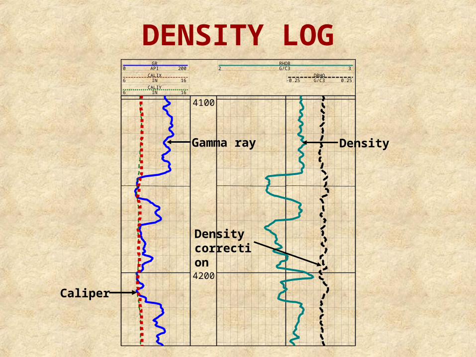
GRAPI0 200
CALIXIN6 16
CALIYIN6 16
RHOBG/C32 3
DRHOG/C3-0.25 0.25
4100
4200
DENSITY LOG
Caliper
Density correction
Gamma ray Density
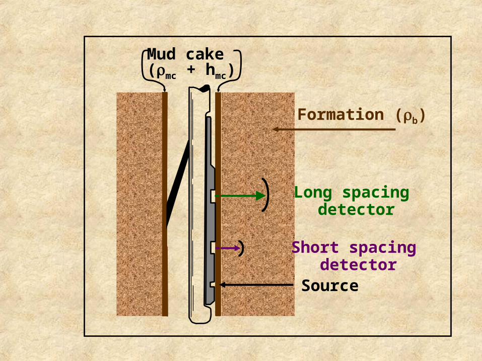
Formation (b)
Long spacing detector
Short spacing detector
Mud cake(mc + hmc)
Source
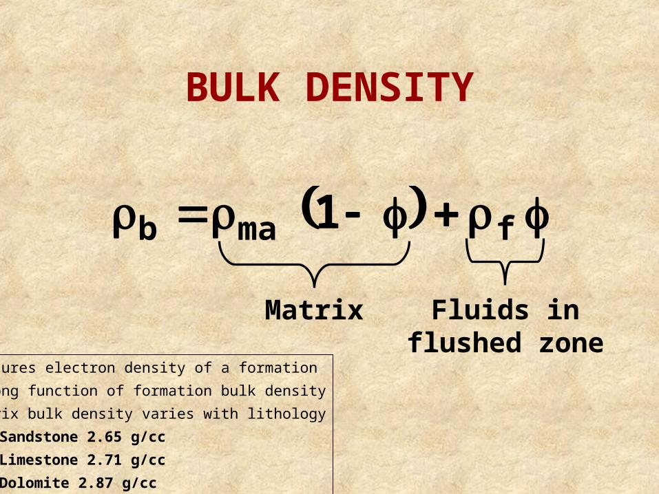
BULK DENSITY
fmab 1
Matrix Fluids influshed zone
•Measures electron density of a formation
•Strong function of formation bulk density
•Matrix bulk density varies with lithology
–Sandstone 2.65 g/cc
–Limestone 2.71 g/cc
–Dolomite 2.87 g/cc
POROSITY FROM DENSITY LOG
Porosity equation
xohxomff S1S
fma
bma
Fluid density equation
We usually assume the fluid density (f) is between 1.0 and 1.1. If gas is present, the actual f will be < 1.0 and the calculated porosity will be too high.
mf is the mud filtrate density, g/cc
h is the hydrocarbon density, g/cc
Sxo is the saturation of the flush/zone, decimal
DENSITY LOGS
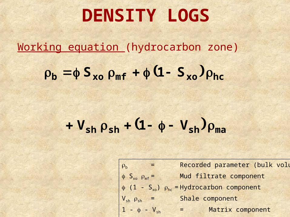
Working equation (hydrocarbon zone)
mashshsh
hcxomfxob
V1V
S1S
b = Recorded parameter (bulk volume)
Sxo mf = Mud filtrate component
(1 - Sxo) hc = Hydrocarbon component
Vsh sh = Shale component
1 - - Vsh = Matrix component
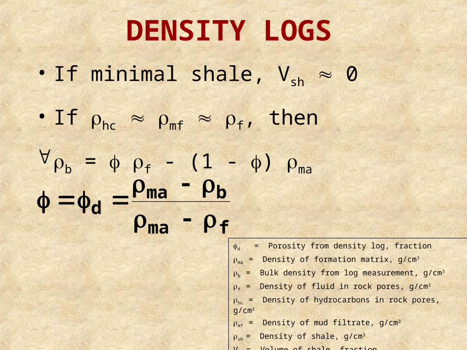
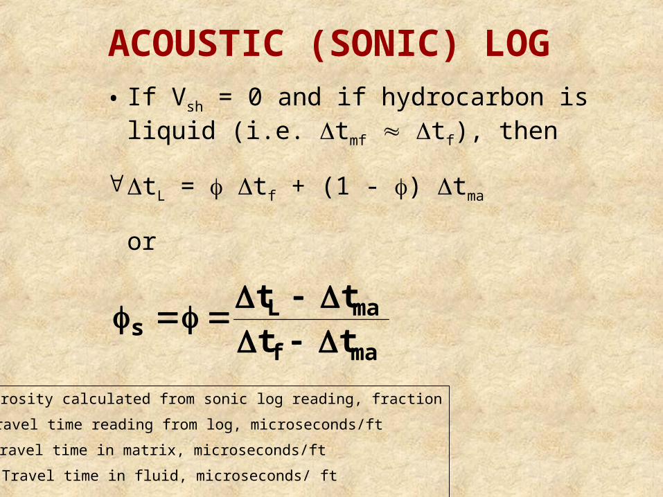
DENSITY LOGS• If minimal shale, Vsh 0
• If hc mf f, then
b = f - (1 - ) ma
fma
bmad
d = Porosity from density log, fraction
ma = Density of formation matrix, g/cm3
b = Bulk density from log measurement, g/cm3
f = Density of fluid in rock pores, g/cm3
hc = Density of hydrocarbons in rock pores, g/cm3
mf = Density of mud filtrate, g/cm3
sh = Density of shale, g/cm3
Vsh = Volume of shale, fraction
Sxo = Mud filtrate saturation in zone invaded by mud filtrate, fraction
GRC0 150
SPCMV-160 40ACAL
6 16
ILDC0.2 200
SNC0.2 200
MLLCF0.2 200
RHOC1.95 2.95
CNLLC0.45 -0.15
DTus/f150 50
001) BONANZA 1
10700
10800
10900
BULK DENSITY LOG
Bulk DensityLog
RHOC
1.95 2.95
NEUTRON LOG
• Logging tool emits high energy neutrons into formation
• Neutrons collide with nuclei of formation’s atoms
• Neutrons lose energy (velocity) with each collision
NEUTRON LOG
• The most energy is lost when colliding with a hydrogen atom nucleus
• Neutrons are slowed sufficiently to be captured by nuclei
• Capturing nuclei become excited and emit gamma rays
NEUTRON LOG• Depending on type of logging tool either gamma rays
or non-captured neutrons are recorded
• Log records porosity based on neutrons captured by formation
• If hydrogen is in pore space, porosity is related to the ratio of neutrons emitted to those counted as captured
• Neutron log reports porosity, calibrated assuming calcite matrix and fresh water in pores, if these assumptions are invalid we must correct the neutron porosity value
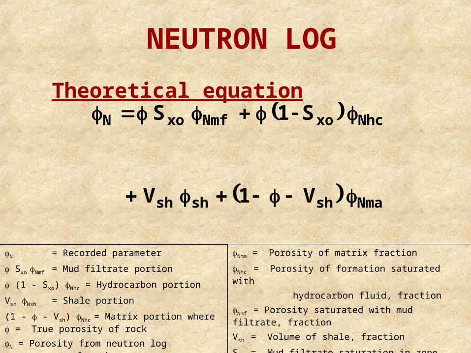
NEUTRON LOG
Theoretical equation
Nmashshsh
NhcxoNmfxoN
V1V
S1S
N = Recorded parameter
Sxo Nmf = Mud filtrate portion
(1 - Sxo) Nhc = Hydrocarbon portion
Vsh Nsh = Shale portion
(1 - - Vsh) Nhc = Matrix portion where = True porosity of rock
N = Porosity from neutron log measurement, fraction
Nma = Porosity of matrix fraction
Nhc = Porosity of formation saturated with
hydrocarbon fluid, fraction
Nmf = Porosity saturated with mud filtrate, fraction
Vsh = Volume of shale, fraction
Sxo = Mud filtrate saturation in zone invadedby mud filtrate, fraction
GRC0 150
SPCMV-160 40ACAL
6 16
ILDC0.2 200
SNC0.2 200
MLLCF0.2 200
RHOC1.95 2.95
CNLLC0.45 -0.15
DTus/f150 50
001) BONANZA 1
10700
10800
10900
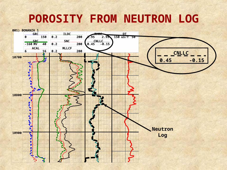
POROSITY FROM NEUTRON LOG
NeutronLog
CNLLC
0.45 -0.15
Upper transmitter
Lower transmitter
R1
R2
R3
R4
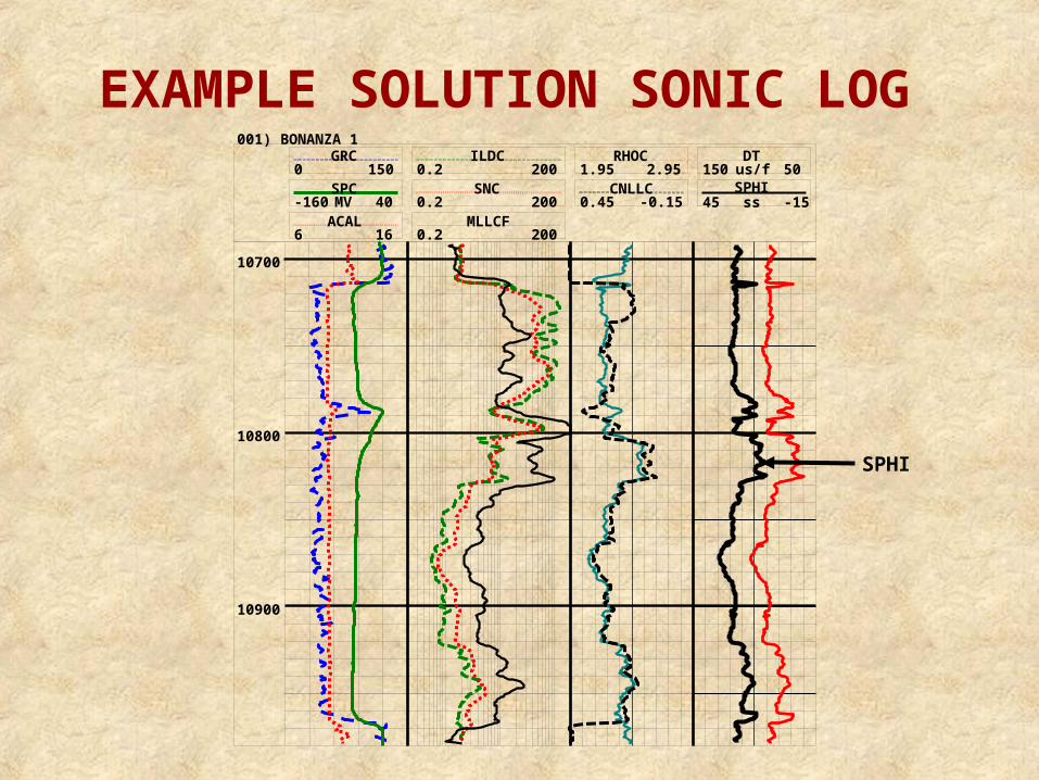
ACOUSTIC (SONIC) LOG
• Tool usually consists of one sound transmitter (above) and two receivers (below)
• Sound is generated, travels through formation
• Elapsed time between sound wave at receiver 1 vs receiver 2 is dependent upon density of medium through which the sound traveled