AFRL-IF-RS-TR-2005-189 Final Technical Report May 2005 TURBINE ENGINE MONITORING SYSTEM (TEMS) LONG TERM SUPPORT INFRASTRUCTURE Giordano Automation Corporation APPROVED FOR PUBLIC RELEASE; DISTRIBUTION UNLIMITED. AIR FORCE RESEARCH LABORATORY INFORMATION DIRECTORATE ROME RESEARCH SITE ROME, NEW YORK
Transcript
AFRL-IF-RS-TR-2005-189 Final Technical Report May 2005 TURBINE ENGINE MONITORING SYSTEM (TEMS) LONG TERM SUPPORT INFRASTRUCTURE Giordano Automation Corporation
APPROVED FOR PUBLIC RELEASE; DISTRIBUTION UNLIMITED.
AIR FORCE RESEARCH LABORATORY INFORMATION DIRECTORATE
ROME RESEARCH SITE ROME, NEW YORK
STINFO FINAL REPORT This report has been reviewed by the Air Force Research Laboratory, Information Directorate, Public Affairs Office (IFOIPA) and is releasable to the National Technical Information Service (NTIS). At NTIS it will be releasable to the general public, including foreign nations. AFRL-IF-RS-TR-2005-189 has been reviewed and is approved for publication APPROVED: /s/
JAMES M. NAGY Project Engineer
FOR THE DIRECTOR: /s/
JOSEPH CAMERA, Chief Information & Intelligence Exploitation Division Information Directorate
REPORT DOCUMENTATION PAGE Form Approved
OMB No. 074-0188 Public reporting burden for this collection of information is estimated to average 1 hour per response, including the time for reviewing instructions, searching existing data sources, gathering and maintaining the data needed, and completing and reviewing this collection of information. Send comments regarding this burden estimate or any other aspect of this collection of information, including suggestions for reducing this burden to Washington Headquarters Services, Directorate for Information Operations and Reports, 1215 Jefferson Davis Highway, Suite 1204, Arlington, VA 22202-4302, and to the Office of Management and Budget, Paperwork Reduction Project (0704-0188), Washington, DC 20503 1. AGENCY USE ONLY (Leave blank)
2. REPORT DATEMAY 2005
3. REPORT TYPE AND DATES COVERED Final Sep 00 – Sep 04
4. TITLE AND SUBTITLE TURBINE ENGINE MONITORING SYSTEM (TEMS) LONG TERM SUPPORT INFRASTRUCTURE
6. AUTHOR(S) Mary Nolan, Gerard Giordano, Al Esser and Gregory deMare
5. FUNDING NUMBERS C - F30602-00-C-0229 PE - 606070 PR - TEMS TA - 01 WU - 03
7. PERFORMING ORGANIZATION NAME(S) AND ADDRESS(ES) Giordano Automation Corporation 21 White Deer Plaza Sparta New Jersey 07871
8. PERFORMING ORGANIZATION REPORT NUMBER
N/A
9. SPONSORING / MONITORING AGENCY NAME(S) AND ADDRESS(ES) Air Force Research Laboratory/IFED 525 Brooks Road Rome New York 13441-4505
10. SPONSORING / MONITORING AGENCY REPORT NUMBER
AFRL-IF-RS-TR-2005-189
11. SUPPLEMENTARY NOTES AFRL Project Engineer: James M. Nagy/IFED/(315) 330-3173/ [email protected]
12a. DISTRIBUTION / AVAILABILITY STATEMENT APPROVED FOR PUBLIC RELEASE; DISTRIBUTION UNLIMITED.
12b. DISTRIBUTION CODE
13. ABSTRACT (Maximum 200 Words) Under this contract, initiatives were conducted to improve the sustainment of the Turbine Engine Monitoring System (TEMS). TEMS is deployed on the A-10 and KC-135 aircraft to monitor engine parameters and provide alerts to the ground crew upon the occurrence of Malfunction Transactions (MALTRAN). The TEMS system was designed around 1970’s technology, and has numerous sustainment issues because of aging and diminishing manufacturing source (DMS) issues. This program was conducted under a Program Research and Development Authority (PRDA) effort. The efforts represent a true partnership between the two sides of the Air Force that rarely communicate: the R&D side represented by AFRL, and the post-deployment sustainment organization, WR-ALC. The partnership focused on introducing new technologies and innovative solutions to sustainment, and at the same time, provided clear insight to the R&D community the logistic impacts of early design decisions. This Final Report details the various initiatives performed as well as the overall results of each initiative. This includes UDU TPS Development, TEMS CCA TPS Re-Host, TEMS FFSCU Re-Engineering, AGETS Long Term Sustainment Study, AGETS Relay Study, AGETS System Upgrades, AGETS Software Support, FFSCU Emergency Repair for KC-135, A-10 Mishap Investigation, Loop Tester Study: Alternative to Hosting of AIS Functions, and EPU Download
15. NUMBER OF PAGES40
14. SUBJECT TERMS Test Program Set Development, Model Based Reasoning, Turbine Engine Monitoring System, TEMS 16. PRICE CODE
17. SECURITY CLASSIFICATION OF REPORT
UNCLASSIFIED
18. SECURITY CLASSIFICATION OF THIS PAGE
UNCLASSIFIED
19. SECURITY CLASSIFICATION OF ABSTRACT
UNCLASSIFIED
20. LIMITATION OF ABSTRACT
ULNSN 7540-01-280-5500 Standard Form 298 (Rev. 2-89)
2.0 DIAGNOSTICIAN TECHNOLOGY............................................................................................ 2 2.1 DIAGNOSTICIAN IMPLEMENTATION IN A TEST PROGRAM SET - A SOFTWARE ENGINEERING PERSPECTIVE .............................................................................................................................................. 5 2.2 DIAGNOSTICIAN RUN-TIME OPERATION........................................................................................ 9
3.0 SUMMARY OF TASKS PERFORMED UNDER CONTRACT AND TASK RESULTS ..... 13 3.1 TEMS SUSTAINMENT ACTIVITIES ............................................................................................... 13
3.1.2.1 Test Station Environment.............................................................................................................. 14 3.1.2.2 APST Control and Support Software ............................................................................................ 14 3.1.2.3 Re-Host the TEMS SRU Test Program Sets ................................................................................. 15 3.1.2.4 Sequence of Tasks to Re-host the TEMS SRU Test Programs ..................................................... 15 3.1.2.5 Certification of TEMS SRU Test Programs .................................................................................. 17 3.1.2.6 Development of Test Program Instructions for Designated UUT TPSs ........................................ 17 3.1.2.7 CSCI Delivery............................................................................................................................... 18
3.2 TEMS FUEL FLOW SIGNAL CONDITIONING UNIT (FFSCU) RE-ENGINEERING............................ 21 3.3 TEMS IEPU LRU DEPOT TEST PROGRAM SET (RE-DIRECTED) .................................................. 26 3.4 AGETS........................................................................................................................................ 26
3.4.1 AGETS Long Term Sustainment Study ................................................................................ 26 3.4.2 AGETS Relay Study............................................................................................................... 27 3.4.3 AGETS System Upgrades ...................................................................................................... 27 3.4.4 AGETS Software Support (OnBoard Software Subcontract) .............................................. 27
3.5 UDAS TEST AT LM AERO........................................................................................................... 28 3.6 IEPU TPS TASK RE-DIRECTION ............................................................................................ 29
3.6.1 FFSCU Emergency Repair for KC-135 ................................................................................ 29 3.6.2 Mishap Investigation ............................................................................................................. 29 3.6.3 Tear-down & Quote ............................................................................................................... 30 3.6.4 Loop Tester Study of Best Alternative to Hosting of AIS Functions ................................... 31 3.6.5 EPU Download Problem Investigation ................................................................................. 31
4.0 APPENDIX A - LIST OF DELIVERABLES ............................................................................. 33
ii
LIST OF FIGURES Figure 1: Breaking the Wall between Development and Maintenance..................2 Figure 2: Fault/Symptom Matrix Generated from Design......................................3 Figure 3: Dynamic Diagnostics .............................................................................3 Figure 4: Traditional Test Program Structure........................................................5 Figure 5: Model Based Test Program Structure....................................................6 Figure 6: Diagnostician Interaction with Test Program..........................................7 Figure 7: Go/No-Go Control Mode......................................................................10 Figure 8: Diagnostician Control Mode.................................................................10 Figure 9: Mixed Control Mode.............................................................................11 Figure 10: Diagnostician Integration into LabVIEW Environment .......................12 Figure 11: EPU 091350 Configuration Slot A6 CSCI Delivery ...........................19 Figure 12: EPU 9383755-10 Configuration Slot A8 CSCI Delivery ....................20 Figure 13: Letter of Certification of APEX ...........................................................23 Figure 14: FFSCU Design Information provided by APEX..................................25
iii
LIST OF TABLES
Table 1: TEMS UDU SRU Test Program Sets....................................................13 Table 2: TEMS EPU SRU Test Program Sets Re-Hosted on APST...................15 Table 3: Identification of FFSCU Units................................................................24
1
1.0 Introduction This document is the Final Report under Air Force Research Laboratory (AFRL) contract number F30602-00-C-0229, performed by Giordano Automation Corp., entitled TEMS Long Term Support Infrastructure. Under the contract, initiatives were conducted to improve the sustainment of WR-ALC managed systems, including the Turbine Engine Monitoring System (TEMS) and the Automated Ground Engine Test Set (AGETS). TEMS is deployed on the A-10 and KC-135 aircraft to monitor engine parameters and provide alerts to the ground crew upon the occurrence of Malfunction Transactions (MALTRAN). The TEMS system was designed around 1970’s technology, and has numerous sustainment issues because of aging and diminishing manufacturing source (DMS) issues. AGETS is a test system used to test the F100-100 engines used on the F-15. Giordano Automation’s Diagnostician technology was applied to TEMS test program sets as well as to the AGETS system to improve troubleshooting efficiencies. The Diagnostician technology and the application of this technology to both TEMS and AGETS are described in Section 2 of this report. This program was conducted under a Program Research and Development Authority (PRDA) effort. The efforts represent a true partnership between the two sides of the Air Force that rarely communicate: the R&D side represented by AFRL, and the post-deployment sustainment organization, WR-ALC. The partnership focused on introducing new technologies and innovative solutions to sustainment, and at the same time, provided clear insight to the R&D community the logistic impacts of early design decisions. As a result of the tasks performed under this contract, and the partnership with the depot, TEMS impact on Mission Capable rates has improved significantly. Where TEMS once had one of the highest MICAP rates in the Air Force, MICAP rates are now well in control and are no longer a major issue for TEMS sustainment. Additionally, most of the short-term recommendations made in the AGETS Trade Study have been implemented or initiated by the Air Force and the result is improved AGETS supportability. The Fuel Flow Signal Conditioning Unit (FFSCU), an LRU of the TEMS system, was re-engineered and underwent successful environmental testing. The new design was subsequently tested on the A-10 at Idaho National Guard, Boise, Idaho. Test results indicate that the performance of the new FFSCU is well within the required limits. Based on the results of this test, along the qualification test results, the A-10 SPD has concluded that this asset is fully acceptable to replace the FFSCU as a preferred item replacement. Section 3 of this Final Report describes the various initiatives performed as well as the overall results of each initiative.
2
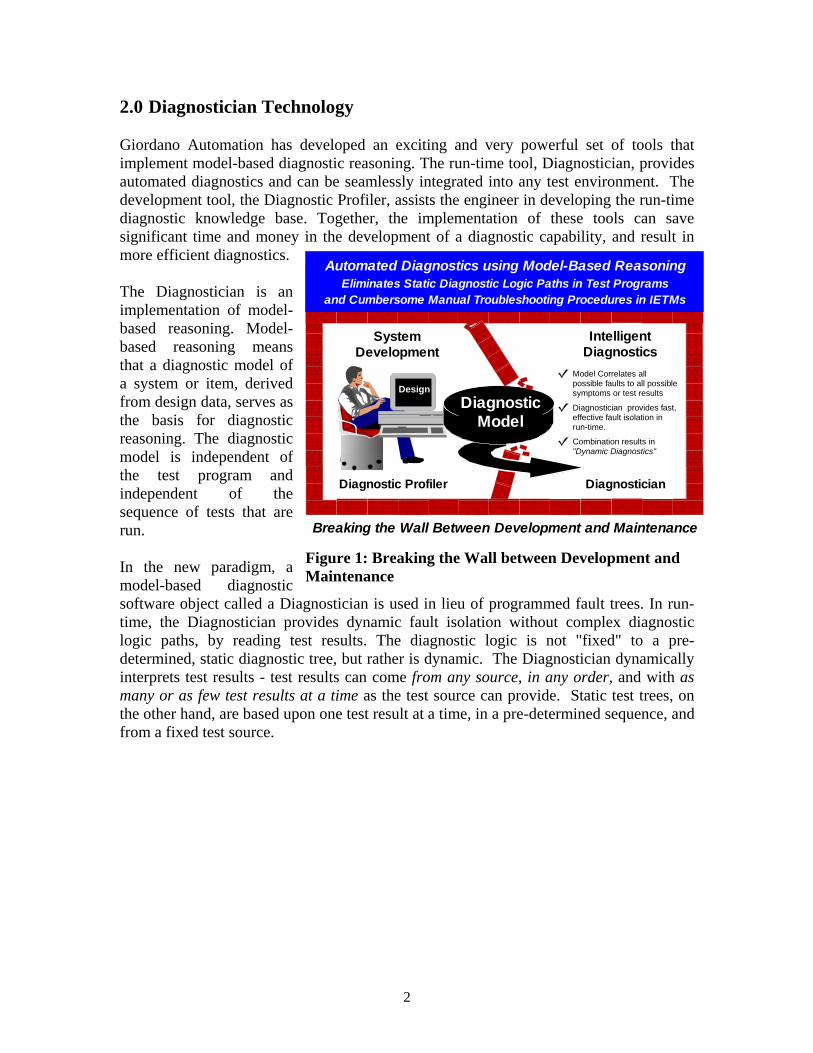
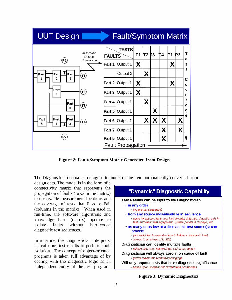
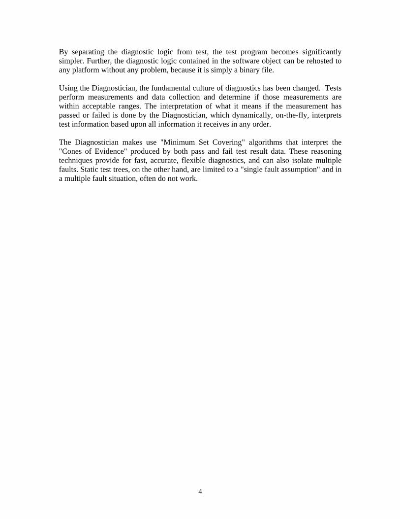
2.0 Diagnostician Technology Giordano Automation has developed an exciting and very powerful set of tools that implement model-based diagnostic reasoning. The run-time tool, Diagnostician, provides automated diagnostics and can be seamlessly integrated into any test environment. The development tool, the Diagnostic Profiler, assists the engineer in developing the run-time diagnostic knowledge base. Together, the implementation of these tools can save significant time and money in the development of a diagnostic capability, and result in more efficient diagnostics. The Diagnostician is an implementation of model-based reasoning. Model-based reasoning means that a diagnostic model of a system or item, derived from design data, serves as the basis for diagnostic reasoning. The diagnostic model is independent of the test program and independent of the sequence of tests that are run. In the new paradigm, a model-based diagnostic software object called a Diagnostician is used in lieu of programmed fault trees. In run-time, the Diagnostician provides dynamic fault isolation without complex diagnostic logic paths, by reading test results. The diagnostic logic is not "fixed" to a pre-determined, static diagnostic tree, but rather is dynamic. The Diagnostician dynamically interprets test results - test results can come from any source, in any order, and with as many or as few test results at a time as the test source can provide. Static test trees, on the other hand, are based upon one test result at a time, in a pre-determined sequence, and from a fixed test source.
Design
Breaking the Wall Between Development and Maintenance
Intelligent Diagnostics
System Development
Diagnostic Model
Model Correlates all possible faults to all possible symptoms or test results
Diagnostician provides fast, effective fault isolation in run-time.
Combination results in "Dynamic Diagnostics"
Diagnostic Profiler Diagnostician
Eliminates Static Diagnostic Logic Paths in Test Programsand Cumbersome Manual Troubleshooting Procedures in IETMs
Automated Diagnostics using Model-Based Reasoning
Figure 1: Breaking the Wall between Development and Maintenance
3
The Diagnostician contains a diagnostic model of the item automatically converted from design data. The model is in the form of a connectivity matrix that represents the propagation of faults (rows in the matrix) to observable measurement locations and the coverage of tests that Pass or Fail (columns in the matrix). When used in run-time, the software algorithms and knowledge base (matrix) operate to isolate faults without hard-coded diagnostic test sequences. In run-time, the Diagnostician interprets, in real time, test results to perform fault isolation. The concept of object-oriented programs is taken full advantage of by dealing with the diagnostic logic as an independent entity of the test program.
Fault/Symptom MatrixUUT Design
AutomaticDesign
Conversion
T1
T2
T3
Part 1 Output 1
Output 2
Part 2 Output 1
Part 3 Output 1
Part 4 Output 1
Part 5 Output 1
Part 6 Output 1
Part 7 Output 1
Part 8 Output 1
FAULTS TESTS
T4
P2
P1
Test
Coverage
Fault Propagation
Part1
Part2
Part3
Part4
Part6
Part7
Part5
Part8
T1 T2 T3 T4 P1 P2
X XX
X XX
XXX X XX
XXX
1
2
Figure 2: Fault/Symptom Matrix Generated from Design
Test Results can be input to the Diagnosticianin any order
(no pre-set sequence)from any source individually or in sequence
operator observations, test instruments, data bus, data file, built-in test, automatic test equipment, system panels & displays, etc.
as many or as few at a time as the test source(s) can provide(not restricted to one-at-a-time to follow a diagnostic tree)zeroes-in on cause of fault(s)
Diagnostician can identify multiple faults(Diagnostic trees follow single-fault assumption)
Diagnostician will always zero in on cause of fault(never leaves the technician hanging)
Will only request tests that have diagnostic significancebased upon snapshot of current fault possibilities
"Dynamic" Diagnostic Capability
Figure 3: Dynamic Diagnostics
4
By separating the diagnostic logic from test, the test program becomes significantly simpler. Further, the diagnostic logic contained in the software object can be rehosted to any platform without any problem, because it is simply a binary file. Using the Diagnostician, the fundamental culture of diagnostics has been changed. Tests perform measurements and data collection and determine if those measurements are within acceptable ranges. The interpretation of what it means if the measurement has passed or failed is done by the Diagnostician, which dynamically, on-the-fly, interprets test information based upon all information it receives in any order. The Diagnostician makes use "Minimum Set Covering" algorithms that interpret the "Cones of Evidence" produced by both pass and fail test result data. These reasoning techniques provide for fast, accurate, flexible diagnostics, and can also isolate multiple faults. Static test trees, on the other hand, are limited to a "single fault assumption" and in a multiple fault situation, often do not work.
5
2.1 Diagnostician Implementation in a Test Program Set - a Software Engineering Perspective
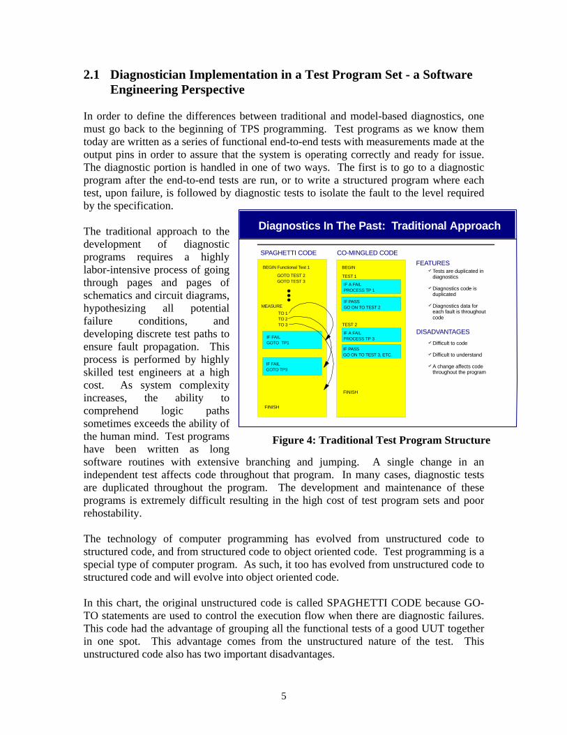
In order to define the differences between traditional and model-based diagnostics, one must go back to the beginning of TPS programming. Test programs as we know them today are written as a series of functional end-to-end tests with measurements made at the output pins in order to assure that the system is operating correctly and ready for issue. The diagnostic portion is handled in one of two ways. The first is to go to a diagnostic program after the end-to-end tests are run, or to write a structured program where each test, upon failure, is followed by diagnostic tests to isolate the fault to the level required by the specification. The traditional approach to the development of diagnostic programs requires a highly labor-intensive process of going through pages and pages of schematics and circuit diagrams, hypothesizing all potential failure conditions, and developing discrete test paths to ensure fault propagation. This process is performed by highly skilled test engineers at a high cost. As system complexity increases, the ability to comprehend logic paths sometimes exceeds the ability of the human mind. Test programs have been written as long software routines with extensive branching and jumping. A single change in an independent test affects code throughout that program. In many cases, diagnostic tests are duplicated throughout the program. The development and maintenance of these programs is extremely difficult resulting in the high cost of test program sets and poor rehostability. The technology of computer programming has evolved from unstructured code to structured code, and from structured code to object oriented code. Test programming is a special type of computer program. As such, it too has evolved from unstructured code to structured code and will evolve into object oriented code. In this chart, the original unstructured code is called SPAGHETTI CODE because GO-TO statements are used to control the execution flow when there are diagnostic failures. This code had the advantage of grouping all the functional tests of a good UUT together in one spot. This advantage comes from the unstructured nature of the test. This unstructured code also has two important disadvantages.
SPAGHETTI CODE CO-MINGLED CODEFEATURES
BEGIN Functional Test 1 BEGIN
TEST 1
FINISH
Tests are duplicated in diagnostics
Diagnostics code is duplicated
Diagnostics data for each fault is throughout code
DISADVANTAGES
Difficult to code
Difficult to understand
A change affects code throughout the program
Diagnostics In The Past: Traditional Approach
GOTO TEST 2GOTO TEST 3
MEASURETO 1TO 2TO 3
IF FAILGOTO TP1
IF FAILGOTO TP3
IF A FAILPROCESS TP 1
IF PASSGO ON TO TEST 2
TEST 2
IF A FAILPROCESS TP 3
IF PASSGO ON TO TEST 3, ETC.
FINISH
Figure 4: Traditional Test Program Structure
6
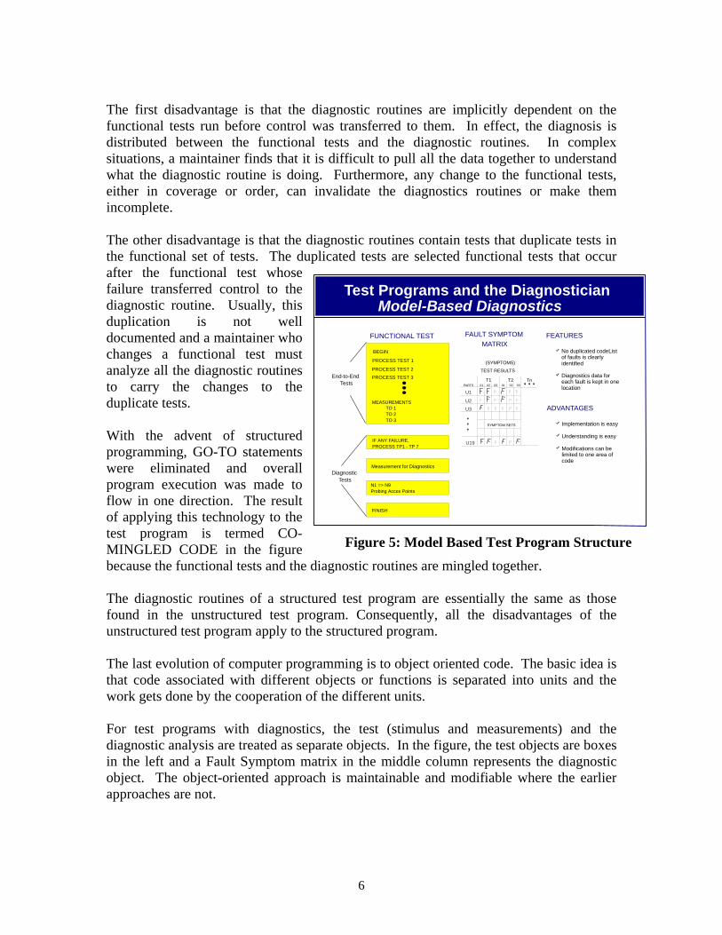
The first disadvantage is that the diagnostic routines are implicitly dependent on the functional tests run before control was transferred to them. In effect, the diagnosis is distributed between the functional tests and the diagnostic routines. In complex situations, a maintainer finds that it is difficult to pull all the data together to understand what the diagnostic routine is doing. Furthermore, any change to the functional tests, either in coverage or order, can invalidate the diagnostics routines or make them incomplete. The other disadvantage is that the diagnostic routines contain tests that duplicate tests in the functional set of tests. The duplicated tests are selected functional tests that occur after the functional test whose failure transferred control to the diagnostic routine. Usually, this duplication is not well documented and a maintainer who changes a functional test must analyze all the diagnostic routines to carry the changes to the duplicate tests. With the advent of structured programming, GO-TO statements were eliminated and overall program execution was made to flow in one direction. The result of applying this technology to the test program is termed CO-MINGLED CODE in the figure because the functional tests and the diagnostic routines are mingled together. The diagnostic routines of a structured test program are essentially the same as those found in the unstructured test program. Consequently, all the disadvantages of the unstructured test program apply to the structured program. The last evolution of computer programming is to object oriented code. The basic idea is that code associated with different objects or functions is separated into units and the work gets done by the cooperation of the different units. For test programs with diagnostics, the test (stimulus and measurements) and the diagnostic analysis are treated as separate objects. In the figure, the test objects are boxes in the left and a Fault Symptom matrix in the middle column represents the diagnostic object. The object-oriented approach is maintainable and modifiable where the earlier approaches are not.
Test Programs and the DiagnosticianModel-Based Diagnostics
FUNCTIONAL TEST
BEGIN
PROCESS TEST 1
PROCESS TEST 2
Measurement for Diagnostics
FAULT SYMPTOMMATRIX
No duplicated codeList of faults is clearly identified
Diagnostics data for each fault is kept in one location
Implementation is easy
Understanding is easy
Modifications can be limited to one area of code
FEATURES
ADVANTAGES
PROCESS TEST 3
MEASUREMENTSTO 1TO 2TO 3
N1 => N9 Probing Acces Points
FINISH
IF ANY FAILURE, PROCESS TP1 - TP 7
030201030201
SYMPTOM SETS
(SYMPTOMS)
TEST RESULTS
PARTS
U1
U19
U3
U2
T1 T2 TnEnd-to-End
Tests
DiagnosticTests
Figure 5: Model Based Test Program Structure
7
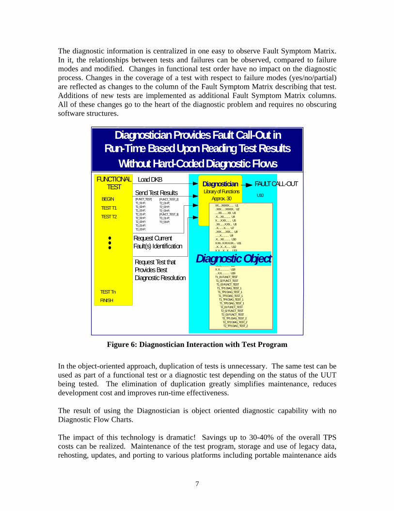
The diagnostic information is centralized in one easy to observe Fault Symptom Matrix. In it, the relationships between tests and failures can be observed, compared to failure modes and modified. Changes in functional test order have no impact on the diagnostic process. Changes in the coverage of a test with respect to failure modes (yes/no/partial) are reflected as changes to the column of the Fault Symptom Matrix describing that test. Additions of new tests are implemented as additional Fault Symptom Matrix columns. All of these changes go to the heart of the diagnostic problem and requires no obscuring software structures.
FUNCTIONAL TEST
BEGIN
TEST T1
TEST T2
TEST Tn
FINISH
DiagnosticianSend Test Results
Load DKB
Diagnostician Provides Fault Call-Out in Run-Time Based Upon Reading Test Results
Request Test that Provides Best Diagnostic Resolution
Library of FunctionsApprox. 30
Diagnostic Object
Figure 6: Diagnostician Interaction with Test Program
In the object-oriented approach, duplication of tests is unnecessary. The same test can be used as part of a functional test or a diagnostic test depending on the status of the UUT being tested. The elimination of duplication greatly simplifies maintenance, reduces development cost and improves run-time effectiveness. The result of using the Diagnostician is object oriented diagnostic capability with no Diagnostic Flow Charts. The impact of this technology is dramatic! Savings up to 30-40% of the overall TPS costs can be realized. Maintenance of the test program, storage and use of legacy data, rehosting, updates, and porting to various platforms including portable maintenance aids
8
are all enabled by the new paradigm. And, a Maintenance Simulator is available which allows the user to simulate the diagnostic effectiveness achieved before committing to coding the test software or building the system hardware or test hardware. Concurrent engineering of support for diagnostics is now a reality! The Diagnostic Profiler supports the development of the diagnostic software object (the diagnostic model). The selection of test points and the assessment of fault isolation probabilities as well as validation of these probabilities are all done using the Diagnostic Profiler during development of the TPS. Diagnostic engineering and test engineering are uncoupled. Test programming tools are used to write tests. In the process of writing these tests, the test engineer must define Pass/Fail (P/F) criteria for each response value being measured and convert test result data for each measured parameter into a P (Pass) or F (Fail). This function can be implemented utilizing a simple high level language subroutine which accepts measurement test results and associated tolerances values as inputs and outputs a "P/F" character. Use of the diagnostic object in run-time to perform fault isolation is done by the Diagnostician. To incorporate diagnostics into the test program, a single "WHILE" loop can be used: WHILE there is another test that can further isolate the fault, ask the Diagnostician for the next optimum test to perform, run that test, and send test results to the Diagnostician. The methodology described is straightforward and well within the responsibilities and expertise of a test engineer. Utilizing the Diagnostician paradigm, the test engineer focuses on what he does and knows best: testing. The specifics of diagnosis, which is a function of UUT topology and behavior, is left to automated reasoning algorithms, which are better suited than a human in resolving complex diagnostic situations. In addition to reducing TPS development time and cost, the model-based diagnostics reasoning approach is easily updated for design changes and allows fault simulation for diagnostics Verification and Validation (V&V).
9
2.2 Diagnostician Run-Time Operation The DiagnosticianTM is a major innovation to the overall test process. To support embedded and off-line applications, the run-time DiagnosticianTM has been designed to operate in a myriad of host platforms.
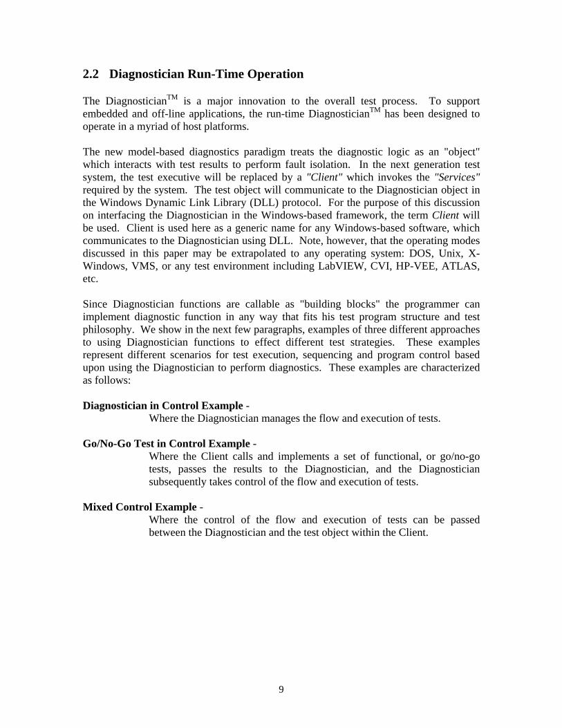
The new model-based diagnostics paradigm treats the diagnostic logic as an "object" which interacts with test results to perform fault isolation. In the next generation test system, the test executive will be replaced by a "Client" which invokes the "Services" required by the system. The test object will communicate to the Diagnostician object in the Windows Dynamic Link Library (DLL) protocol. For the purpose of this discussion on interfacing the Diagnostician in the Windows-based framework, the term Client will be used. Client is used here as a generic name for any Windows-based software, which communicates to the Diagnostician using DLL. Note, however, that the operating modes discussed in this paper may be extrapolated to any operating system: DOS, Unix, X-Windows, VMS, or any test environment including LabVIEW, CVI, HP-VEE, ATLAS, etc. Since Diagnostician functions are callable as "building blocks" the programmer can implement diagnostic function in any way that fits his test program structure and test philosophy. We show in the next few paragraphs, examples of three different approaches to using Diagnostician functions to effect different test strategies. These examples represent different scenarios for test execution, sequencing and program control based upon using the Diagnostician to perform diagnostics. These examples are characterized as follows: Diagnostician in Control Example -
Where the Diagnostician manages the flow and execution of tests. Go/No-Go Test in Control Example - Where the Client calls and implements a set of functional, or go/no-go
tests, passes the results to the Diagnostician, and the Diagnostician subsequently takes control of the flow and execution of tests.
Mixed Control Example -
Where the control of the flow and execution of tests can be passed between the Diagnostician and the test object within the Client.
10
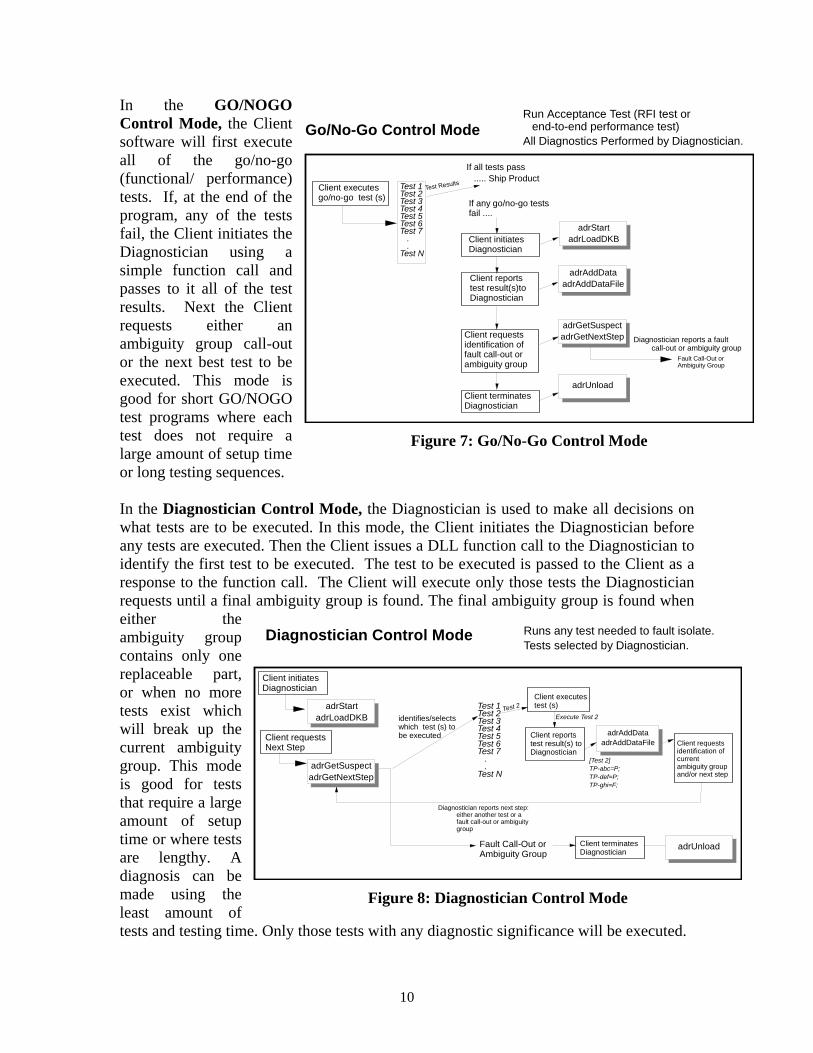
In the GO/NOGO Control Mode, the Client software will first execute all of the go/no-go (functional/ performance) tests. If, at the end of the program, any of the tests fail, the Client initiates the Diagnostician using a simple function call and passes to it all of the test results. Next the Client requests either an ambiguity group call-out or the next best test to be executed. This mode is good for short GO/NOGO test programs where each test does not require a large amount of setup time or long testing sequences. In the Diagnostician Control Mode, the Diagnostician is used to make all decisions on what tests are to be executed. In this mode, the Client initiates the Diagnostician before any tests are executed. Then the Client issues a DLL function call to the Diagnostician to identify the first test to be executed. The test to be executed is passed to the Client as a response to the function call. The Client will execute only those tests the Diagnostician requests until a final ambiguity group is found. The final ambiguity group is found when either the ambiguity group contains only one replaceable part, or when no more tests exist which will break up the current ambiguity group. This mode is good for tests that require a large amount of setup time or where tests are lengthy. A diagnosis can be made using the least amount of tests and testing time. Only those tests with any diagnostic significance will be executed.
Test 1Test 2Test 3Test 4Test 5Test 6Test 7 . .Test N
Go/No-Go Control Mode
Client initiates Diagnostician
Client executes go/no-go test (s)
Client reports test result(s)to Diagnostician
Client requests identification of fault call-out or ambiguity group
Fault Call-Out or Ambiguity Group
If all tests pass ..... Ship Product
Diagnostician reports a fault call-out or ambiguity group
If any go/no-go tests fail ....
Test Results
Client terminates Diagnostician
Run Acceptance Test (RFI test or end-to-end performance test)
All Diagnostics Performed by Diagnostician.
adrStartadrLoadDKB
adrAddDataadrAddDataFile
adrUnload
adrGetSuspectadrGetNextStep
Figure 7: Go/No-Go Control Mode
Test 1Test 2Test 3Test 4Test 5Test 6Test 7 . .Test N
identifies/selects which test (s) to be executed
Client executes test (s)
Client reports test result(s) to Diagnostician
Client requests identification of current ambiguity group and/or next step
Diagnostician reports next step: either another test or a fault call-out or ambiguity group
[Test 2]TP-abc=P;TP-def=P;TP-ghi=F;
Execute Test 2
Fault Call-Out or Ambiguity Group
Diagnostician Control Mode
Client terminates Diagnostician
Test 2
Runs any test needed to fault isolate.Tests selected by Diagnostician.
Client initiates Diagnostician
adrStartadrLoadDKB
adrAddDataadrAddDataFile
adrUnload
Client requests Next Step
adrGetSuspectadrGetNextStep
Figure 8: Diagnostician Control Mode
11
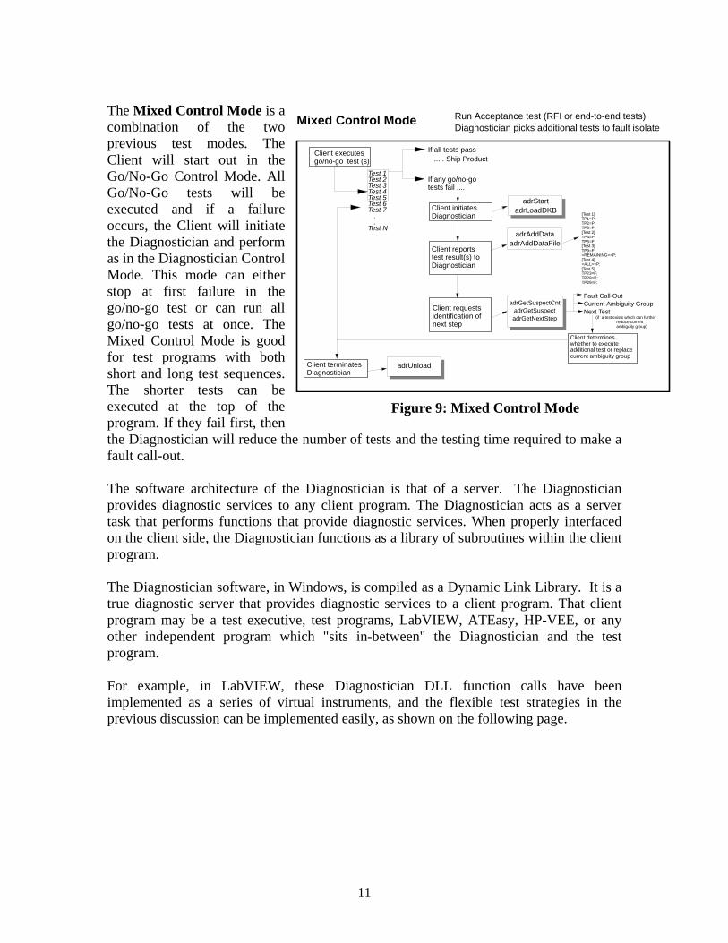
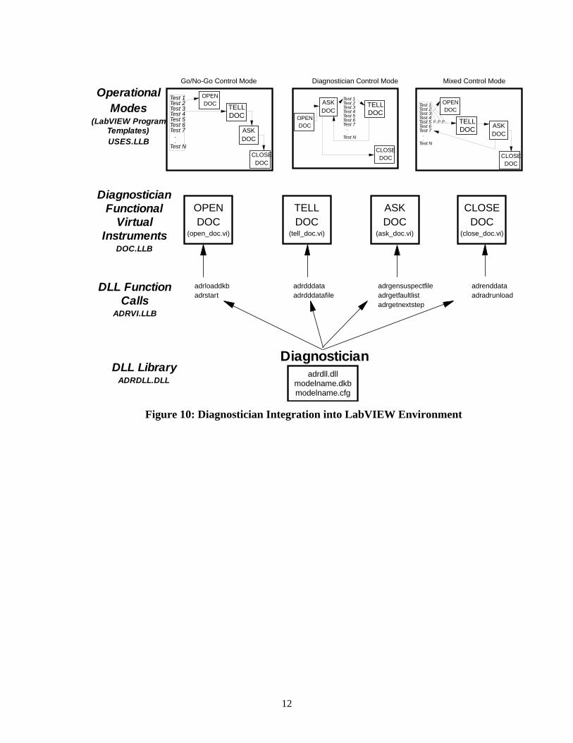
The Mixed Control Mode is a combination of the two previous test modes. The Client will start out in the Go/No-Go Control Mode. All Go/No-Go tests will be executed and if a failure occurs, the Client will initiate the Diagnostician and perform as in the Diagnostician Control Mode. This mode can either stop at first failure in the go/no-go test or can run all go/no-go tests at once. The Mixed Control Mode is good for test programs with both short and long test sequences. The shorter tests can be executed at the top of the program. If they fail first, then the Diagnostician will reduce the number of tests and the testing time required to make a fault call-out. The software architecture of the Diagnostician is that of a server. The Diagnostician provides diagnostic services to any client program. The Diagnostician acts as a server task that performs functions that provide diagnostic services. When properly interfaced on the client side, the Diagnostician functions as a library of subroutines within the client program. The Diagnostician software, in Windows, is compiled as a Dynamic Link Library. It is a true diagnostic server that provides diagnostic services to a client program. That client program may be a test executive, test programs, LabVIEW, ATEasy, HP-VEE, or any other independent program which "sits in-between" the Diagnostician and the test program. For example, in LabVIEW, these Diagnostician DLL function calls have been implemented as a series of virtual instruments, and the flexible test strategies in the previous discussion can be implemented easily, as shown on the following page.
Client initiates Diagnostician
Client executes go/no-go test (s)
Client reports test result(s) to Diagnostician
Fault Call-OutCurrent Ambiguity GroupNext Test
If all tests pass ..... Ship Product
If any go/no-go tests fail ....
Client terminates Diagnostician
Test 1Test 2Test 3Test 4Test 5Test 6Test 7 . .Test N
Client requests identification of next step
(if a test exists which can further reduce current ambiguity group)
Mixed Control Mode
Client determines whether to execute additional test or replace current ambiguity group
Run Acceptance test (RFI or end-to-end tests)Diagnostician picks additional tests to fault isolate
adrStartadrLoadDKB
adrAddDataadrAddDataFile
adrUnload
adrGetSuspectCntadrGetSuspectadrGetNextStep
Figure 9: Mixed Control Mode
12
adrdll.dllmodelname.dkbmodelname.cfg
DLL Function Calls
ADRVI.LLB
Diagnostician Functional
Virtual Instruments
DOC.LLB
OperationalModes
(LabVIEW Program Templates)USES.LLB
adrloaddkbadrstart
ASKDOC
(ask_doc.vi)
OPENDOC
(open_doc.vi)
TELLDOC
(tell_doc.vi)
CLOSEDOC
(close_doc.vi)
Diagnostician Control Mode
ASKDOC
OPENDOC
TELLDOC
CLOSEDOC
Test 1Test 2Test 3Test 4Test 5Test 6Test 7 . .Test N
Go/No-Go Control Mode Mixed Control Mode
Diagnostician
adrdddataadrdddatafile
adrgensuspectfileadrgetfaultlistadrgetnextstep
adrenddataadradrunload
ASKDOC
OPENDOC
TELLDOC
CLOSEDOC
Test 1Test 2Test 3Test 4Test 5Test 6Test 7 . .Test N
F P P
Test 1Test 2Test 3Test 4Test 5Test 6Test 7 . .Test N
OPENDOC
CLOSEDOC
TELLDOC
ASKDOC
DLL LibraryADRDLL.DLL
Figure 10: Diagnostician Integration into LabVIEW Environment
13
3.0 Summary of Tasks Performed Under Contract and Task Results 3.1 TEMS Sustainment Activities A number of activities were performed to improve the overall sustainability of the TEMS system. These activities, their results, and deliverables are defined in the following paragraphs. 3.1.1 UDU TPS Test Program Sets (TPS) were developed for the Shop Replaceable Units (SRU) of the TEMS Umbilical Display Unit (UDU). These TPS were developed using Giordano Automation’s Diagnostician to provide automated diagnostic capability. The SRUs for which TPS were developed have the following designations:
Table 1: TEMS UDU SRU Test Program Sets CPIN SRU TEMS UDU Nomenclature
85E-USQ85/M390-U001-00A 090280 Display CCA 85E-USQ85/M390-U002-00A 090285 Switching A 85E-USQ85/M390-U003-00A 090290 Switching B
3.1.2 TEMS CCA TPS Re-Host The major objective of this effort was to re-host selected TEMS SRUs from the MATE 390 test station to the APST test station. The MATE 390 Test Programs were enhanced in a previous contract using Giordano Automation’s powerful set of tools that implement model based diagnostic reasoning. The run-time tool, the Diagnostician, provides automated diagnostics and can be seamlessly integrated into any test environment. Since the Diagnostician is platform independent and all the diagnostic logic is contained in a binary file called the Diagnostic Knowledge Base (DKB), porting the SRUs from MATE 390 Atlas to APST LabWindows CVI environment was easily accomplished at a reduced cost while preserving 100% of the diagnostic knowledge. The Diagnostician has proven that the re-hosting and porting of the TEMS TPSs to a new platform (APST Tester) was easily accomplished at a reduced risk and cost. The three main reasons that this was achieved: the platform independent diagnostics, easier porting of stand-alone test code, and the use of the Diagnostic Profiler’s automatic code generation tool. The diagnostic logic was decoupled from the TPS code and represented in a platform independent diagnostic knowledge base. This Diagnostic Knowledge Base (DKB) was simply copied and re-ported to the new platform. The resulting MATE 390 test code was significantly easier to port over to the APST tester. All of the “GOTO” and
14
“IF-THEN-ELSE” statements necessary for coding fault tree diagnostics were removed resulting in smaller, less complex, stand-alone tests. Additionally, the number of probes was reduced while achieving better diagnostics. The code that remained was a collection of stand-alone functional tests and measurements. The straightforward stand-alone nature of these tests made them much easier to analyze. This simplified the ITA design and development to the APST station interface. It was also much simpler to rewrite the functional tests in the LabWindows CVI environment. When the functionally of a test needs to be re-structured, due to the limitations of the APST tester, the Diagnostic Profiler helps in assessing the diagnostic implications. The Diagnostic Profiler’s code generation tool was used to generate the APST TPS automatically. This tool uses two files for input parameters, the Diagnostic Knowledge Base (DKB) that contains all the information about the tests, and an APST specific template file that contains specific information about the APST LabWindows code. The generated TPS has all the APST GUI code, all the diagnostic calls to the Diagnostician, and all of the stub functions for each functional test and measurement. The efforts described in this Final Report were based upon a contract to port and re-host the Diagnostician and the Diagnostic Knowledge Based across selected TEMS EPU circuit cards. The automatic diagnostic reasoning approach that Giordano Automation used in re-hosting the test program sets has been accomplished using a set of tools developed by Giordano Automation. The run-time tool, called the Diagnostician, provides automated diagnostics that is integrated into the Test Program. The development tool, the Diagnostic Profiler was used to create the Diagnostic models.
In our previous contract, we reduced the complexity of the TEMS TPS code by inserting the Diagnostician. The traditional troubleshooting trees that were previously implemented with several, hard to maintain “GOTO” and “IF-THEN-ELSE” statements, were replaced with a simple conversation loop with the Diagnostician. By eliminating this complex diagnostic hard-coded logic, the resulting TPSs are vastly easier to maintain. Also, transporting the modified TPSs and the Diagnostician to an alternate test resource is much more straightforward (APST tester). This approach has also allowed for a significant reduction in the number of lines of code for each Test Program. 3.1.2.1 Test Station Environment
The FT900S Advanced Power Supply Test System (APST) is an existing Test Station located at Warner Robins ALC. The APST is a state of the art environment for power supply testing and repair. The APST is also commonly used to test Shop Replaceable Units (SRUs). 3.1.2.2 APST Control and Support Software
The software used on the APST is National Instrument’s LabWindows CVI. Test programs are written in C using LabWindows CVI libraries. The operation system used on the APST is the MS-Windows 2000 operating system.
15
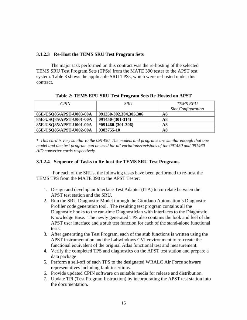
3.1.2.3 Re-Host the TEMS SRU Test Program Sets
The major task performed on this contract was the re-hosting of the selected
TEMS SRU Test Program Sets (TPSs) from the MATE 390 tester to the APST test system. Table 3 shows the applicable SRU TPSs, which were re-hosted under this contract.
Table 2: TEMS EPU SRU Test Program Sets Re-Hosted on APST CPIN SRU TEMS EPU
Slot Configuration 85E-USQ85/APST-U003-00A 091350-302,304,305,306 A6 85E-USQ85/APST-U001-00A 091450-(301-314) A8 85E-USQ85/APST-U001-00A *091460-(301-306) A8 85E-USQ85/APST-U002-00A 9383755-10 A8 * This card is very similar to the 091450. The models and programs are similar enough that one model and one test program can be used for all variations/revisions of the 091450 and 091460 A/D converter cards respectively. 3.1.2.4 Sequence of Tasks to Re-host the TEMS SRU Test Programs For each of the SRUs, the following tasks have been performed to re-host the TEMS TPS from the MATE 390 to the APST Tester:
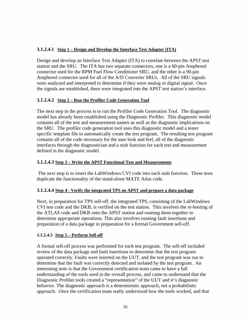
1. Design and develop an Interface Test Adapter (ITA) to correlate between the APST test station and the SRU.
2. Run the SRU Diagnostic Model through the Giordano Automation’s Diagnostic Profiler code generation tool. The resulting test program contains all the Diagnostic hooks to the run-time Diagnostician with interfaces to the Diagnostic Knowledge Base. The newly generated TPS also contains the look and feel of the APST user interface and a stub test function for each of the stand-alone functional tests.
3. After generating the Test Program, each of the stub functions is written using the APST instrumentation and the Labwindows CVI environment to re-create the functional equivalent of the original Atlas functional test and measurement.
4. Verify the completed TPS and diagnostics on the APST test station and prepare a data package
5. Perform a sell-off of each TPS to the designated WRALC Air Force software representatives including fault insertions.
6. Provide updated CPIN software on suitable media for release and distribution. 7. Update TPI (Test Program Instruction) by incorporating the APST test station into
the documentation.
16
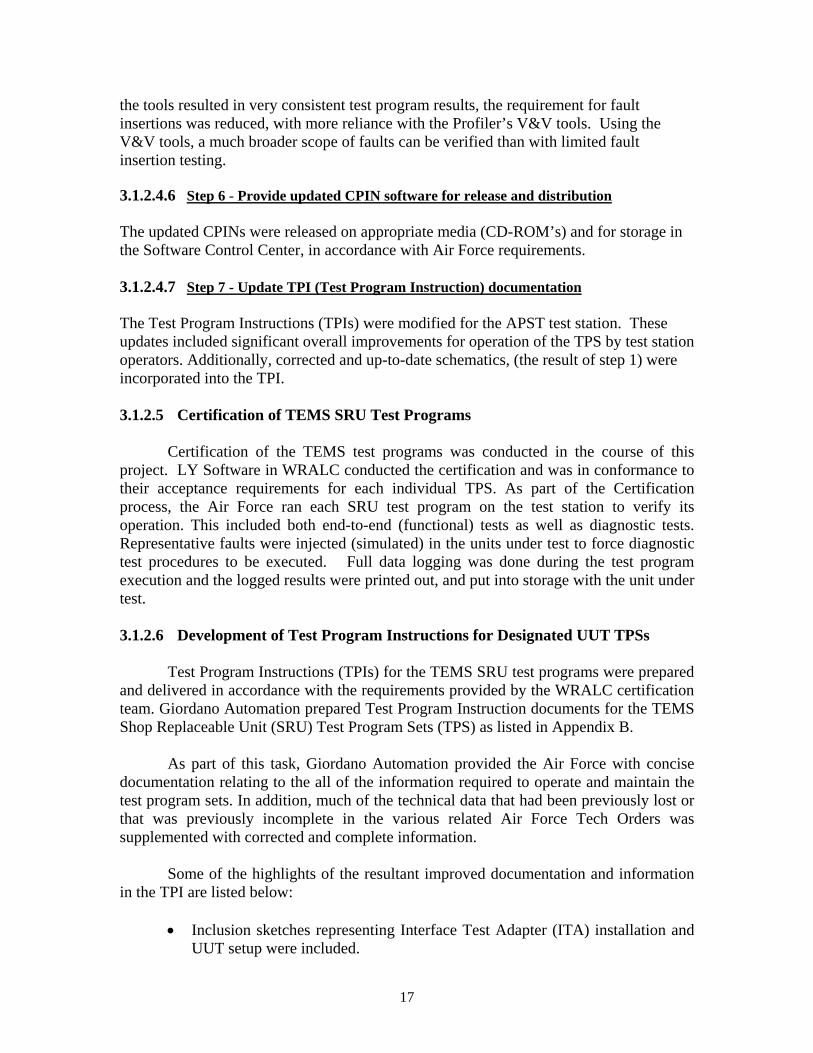
3.1.2.4.1 Step 1 – Design and Develop the Interface Test Adapter (ITA) Design and develop an Interface Test Adapter (ITA) to correlate between the APST test station and the SRU. The ITA has two separate connectors, one is a 60-pin Amphenol connector used for the RPM Fuel Flow Conditioner SRU, and the other is a 90-pin Amphenol connector used for all of the A/D Converter SRUs. All of the SRU signals were analyzed and interpreted to determine if they were analog or digital signal. Once the signals are established, there were integrated into the APST test station’s interface. 3.1.2.4.2 Step 2 – Run the Profiler Code Generation Tool
The next step in the process is to run the Profiler Code Generation Tool. The diagnostic model has already been established using the Diagnostic Profiler. This diagnostic model contains all of the test and measurement names as well as the diagnostic implications on the SRU. The profiler code generation tool uses this diagnostic model and a tester specific template file to automatically create the test program. The resulting test program contains all of the code necessary for the user look and feel, all of the diagnostic interfaces through the diagnostician and a stub function for each test and measurement defined in the diagnostic model. 3.1.2.4.3 Step 3 – Write the APST Functional Test and Measurements The next step is to insert the LabWindows CVI code into each stub function. These tests duplicate the functionality of the stand-alone MATE Atlas code. 3.1.2.4.4 Step 4 - Verify the integrated TPS on APST and prepare a data package Next, in preparation for TPS sell-off, the integrated TPS, consisting of the LabWindows CVI test code and the DKB, is verified on the test station. This involves the re-hosting of the ATLAS code and DKB onto the APST station and running them together to determine appropriate operations. This also involves running fault insertions and preparation of a data package in preparation for a formal Government sell-off. 3.1.2.4.5 Step 5 – Perform Sell-off A formal sell-off process was performed for each test program. The sell-off included review of the data package and fault insertions to determine that the test program operated correctly. Faults were inserted on the UUT, and the test program was run to determine that the fault was correctly detected and isolated by the test program. An interesting note is that the Government certification team came to have a full understanding of the tools used in the overall process, and came to understand that the Diagnostic Profiler tools created a “representation” of the UUT and it’s diagnostic behavior. The diagnostic approach is a deterministic approach, not a probabilistic approach. Once the certification team really understood how the tools worked, and that
17
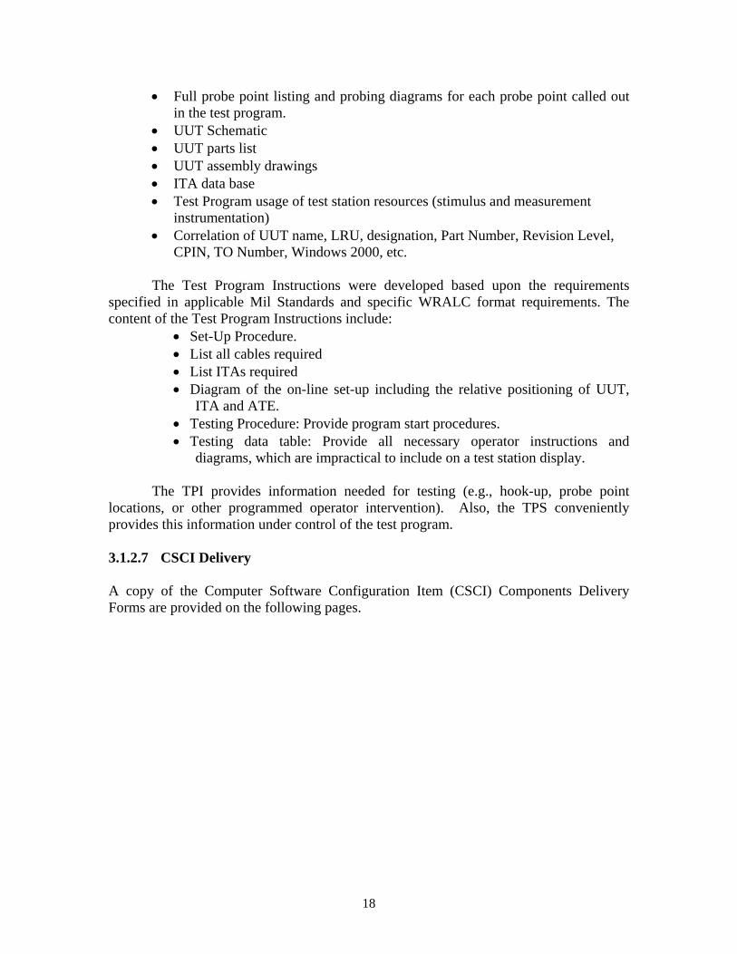
the tools resulted in very consistent test program results, the requirement for fault insertions was reduced, with more reliance with the Profiler’s V&V tools. Using the V&V tools, a much broader scope of faults can be verified than with limited fault insertion testing. 3.1.2.4.6 Step 6 - Provide updated CPIN software for release and distribution The updated CPINs were released on appropriate media (CD-ROM’s) and for storage in the Software Control Center, in accordance with Air Force requirements. 3.1.2.4.7 Step 7 - Update TPI (Test Program Instruction) documentation The Test Program Instructions (TPIs) were modified for the APST test station. These updates included significant overall improvements for operation of the TPS by test station operators. Additionally, corrected and up-to-date schematics, (the result of step 1) were incorporated into the TPI. 3.1.2.5 Certification of TEMS SRU Test Programs Certification of the TEMS test programs was conducted in the course of this project. LY Software in WRALC conducted the certification and was in conformance to their acceptance requirements for each individual TPS. As part of the Certification process, the Air Force ran each SRU test program on the test station to verify its operation. This included both end-to-end (functional) tests as well as diagnostic tests. Representative faults were injected (simulated) in the units under test to force diagnostic test procedures to be executed. Full data logging was done during the test program execution and the logged results were printed out, and put into storage with the unit under test. 3.1.2.6 Development of Test Program Instructions for Designated UUT TPSs Test Program Instructions (TPIs) for the TEMS SRU test programs were prepared and delivered in accordance with the requirements provided by the WRALC certification team. Giordano Automation prepared Test Program Instruction documents for the TEMS Shop Replaceable Unit (SRU) Test Program Sets (TPS) as listed in Appendix B.
As part of this task, Giordano Automation provided the Air Force with concise documentation relating to the all of the information required to operate and maintain the test program sets. In addition, much of the technical data that had been previously lost or that was previously incomplete in the various related Air Force Tech Orders was supplemented with corrected and complete information.
Some of the highlights of the resultant improved documentation and information
in the TPI are listed below:
• Inclusion sketches representing Interface Test Adapter (ITA) installation and UUT setup were included.
18
• Full probe point listing and probing diagrams for each probe point called out in the test program.
• UUT Schematic • UUT parts list • UUT assembly drawings • ITA data base • Test Program usage of test station resources (stimulus and measurement
instrumentation) • Correlation of UUT name, LRU, designation, Part Number, Revision Level,
CPIN, TO Number, Windows 2000, etc.
The Test Program Instructions were developed based upon the requirements specified in applicable Mil Standards and specific WRALC format requirements. The content of the Test Program Instructions include:
• Set-Up Procedure. • List all cables required • List ITAs required • Diagram of the on-line set-up including the relative positioning of UUT,
ITA and ATE. • Testing Procedure: Provide program start procedures. • Testing data table: Provide all necessary operator instructions and
diagrams, which are impractical to include on a test station display.
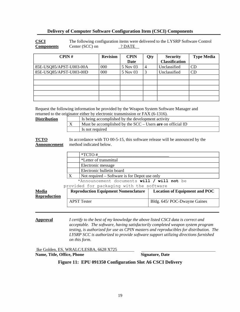
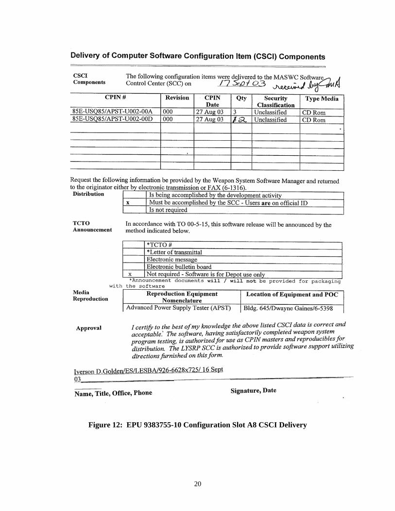
The TPI provides information needed for testing (e.g., hook-up, probe point locations, or other programmed operator intervention). Also, the TPS conveniently provides this information under control of the test program. 3.1.2.7 CSCI Delivery A copy of the Computer Software Configuration Item (CSCI) Components Delivery Forms are provided on the following pages.
19
Delivery of Computer Software Configuration Item (CSCI) Components CSCI Components
The following configuration items were delivered to the LYSRP Software Control Center (SCC) on ? DATE
CPIN # Revision CPIN
Date Qty Security
Classification Type Media
85E-USQ85/APST-U003-00A 000 5 Nov 03 4 Unclassified CD 85E-USQ85/APST-U003-00D 000 5 Nov 03 3 Unclassified CD Request the following information be provided by the Weapon System Software Manager and returned to the originator either by electronic transmission or FAX (6-1316). Distribution Is being accomplished by the development activity X Must be accomplished by the SCC – Users are on official ID Is not required TCTO Announcement
In accordance with TO 00-5-15, this software release will be announced by the method indicated below.
*TCTO #_________________________________ *Letter of transmittal Electronic message Electronic bulletin board X Not required – Software is for Depot use only
*Announcement documents will / will not be provided for packaging with the software
Media Reproduction
Reproduction Equipment Nomenclature Location of Equipment and POC
APST Tester Bldg. 645/ POC-Dwayne Gaines
Approval I certify to the best of my knowledge the above listed CSCI data is correct and
acceptable. The software, having satisfactorily completed weapon system program testing, is authorized for use as CPIN masters and reproducibles for distribution. The LYSRP SCC is authorized to provide software support utilizing directions furnished on this form.
Ike Golden, ES, WRALC/LESBA, 6628 X725 Name, Title, Office, Phone Signature, Date
3.2 TEMS Fuel Flow Signal Conditioning Unit (FFSCU) Re-Engineering
The Fuel Flow Signal Conditioning Unit (FFSCU) is an airborne LRU that reads fuel flow data and provides a corresponding input to the TEMS EPU. The FFSCU has had MICAP issues. The Air Force has no organic test or repair capability for the unit. The OEM has traditionally been unresponsive to Government requirements for repair of units. This is primarily because of the age of the item, the fact that the OEM has gone through various mergers and acquisitions, and because much of the corporate history has been lost. Also, the relatively low demand rate on the part of the Air Force makes this basically a nuisance issue for the OEM. As a result, several years ago, the OEM had raised the cost of repair of FFSCU units to approximately 10K per unit. Additionally, the FFSCU has DMS issues, which make repair difficult. As a result of these issues, the TEMS System Manager initiated a project to re-engineer the FFSCU by a new manufacturer, and, at the same time, provide the organic AF depot with the capability to test the FFSCU. The original intention was to re-engineer a FFSCU to the exact specifications of the original FFSCU. Subsequent discussions with the A-10 SPD resulted in the A-10 requirements for a FFSCU that complies with an updated set of specifications for the A-10 aircraft. A new specification was developed, and the vendor is currently in the process of performing independent laboratory tests for acceptance of the FFSCU. When these tests are successfully completed, flight tests and flight qualification will be initiated with the A-10 SPD. The KC-135 consolidation of data acquisition systems is anticipated to eliminate the use of the FFSCU on the aircraft that undergo the upgrade. However, whether or not the FFSCU function has been successfully integrated into the FDR is an issue. The possibility exists that the FFSCU will continue to be required on the KC-135. If the FFSCU is not required, then there will be a large number of units turned in, and these units can be used as spares. If the FFSCU is indeed required on the KC-135, then supply of good units to both A-10 and KC-135 users will remain an issue. A contract was put in place to accomplish the following:
1. Update the design with new components to eliminate the obsolete components 2. Repair a total of 17 units by either salvaging good modules from returned
units or replacing failed modules with the revised layout. 3. Generate a functional test process and associated hardware/software to
accomplish this testing as an organic Air Force process. 4. Provide design documentation (schematics) at a level necessary to allow for
organic AF functional testing. Based on A-10 updated requirements for environmental characteristics of all items being put on the aircraft, the initial effort was stopped by the TEMS Program Manager at the
22
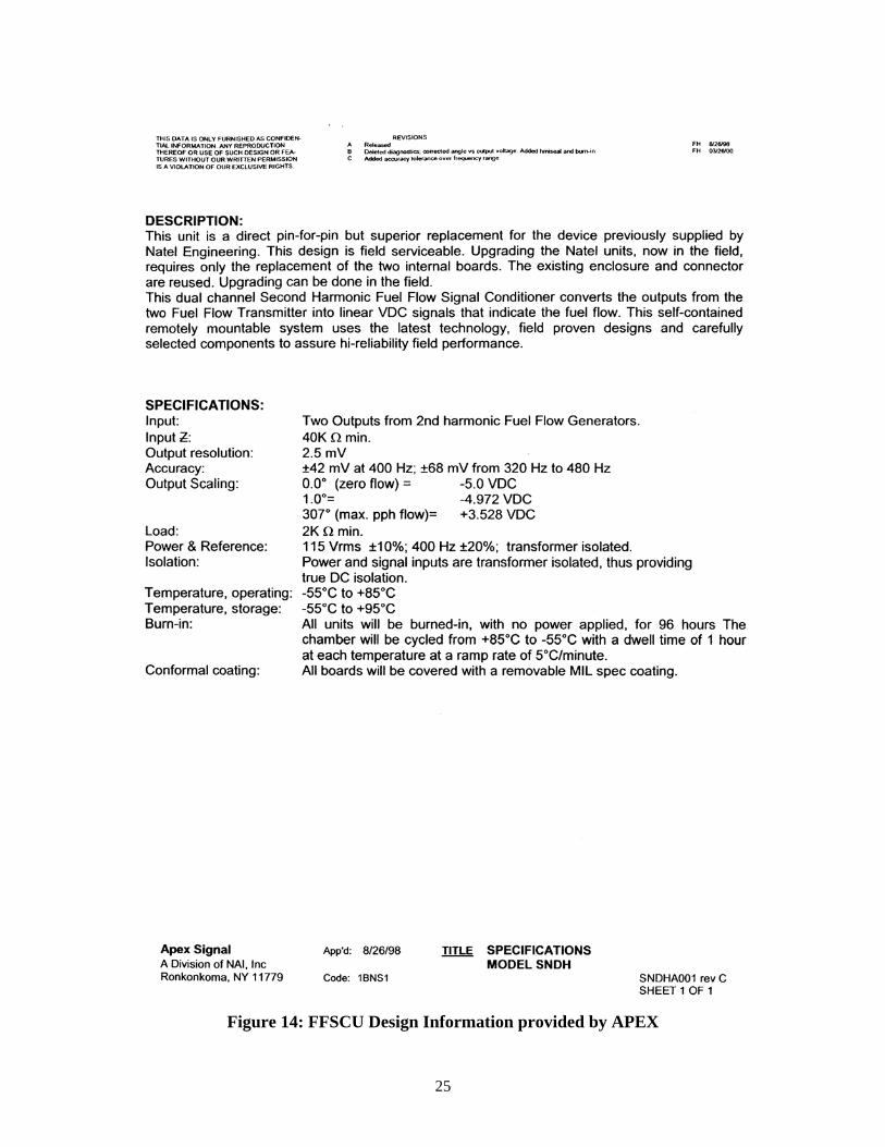
time, David Garza. The program was re-initiated as a FFSCU re-design effort to satisfy A-10 environmental requirements. Giordano Automation worked with the A-10 SPD to identify updated environmental requirements, and prepared an updated FFSCU requirements specification, which was coordinated through the TEMS office and the A-10 SPD. A new effort was initiated with APEX based on the updated specification. The updated FFSCU design was tested through an independent laboratory. The results of this test were documented and provided to the Air Force. The TEMS Equipment Specialist inspected the APEX facilities and processes and certified APEX as an acceptable vendor for the FFSCU. Giordano Automation developed a test program set for the FFSCU for depot level testing. The results of this effort are that Apex successfully completed the environmental Qualification Testing of the re-engineered FFSCU. Two units were shipped to the A10 SPD for Flight Test. The production facility in WRALC is now actively testing and screening FFSCU units organically using the TPS developed, in support of the immediate MICAP needs.
23
Figure 13: Letter of Certification of APEX
24
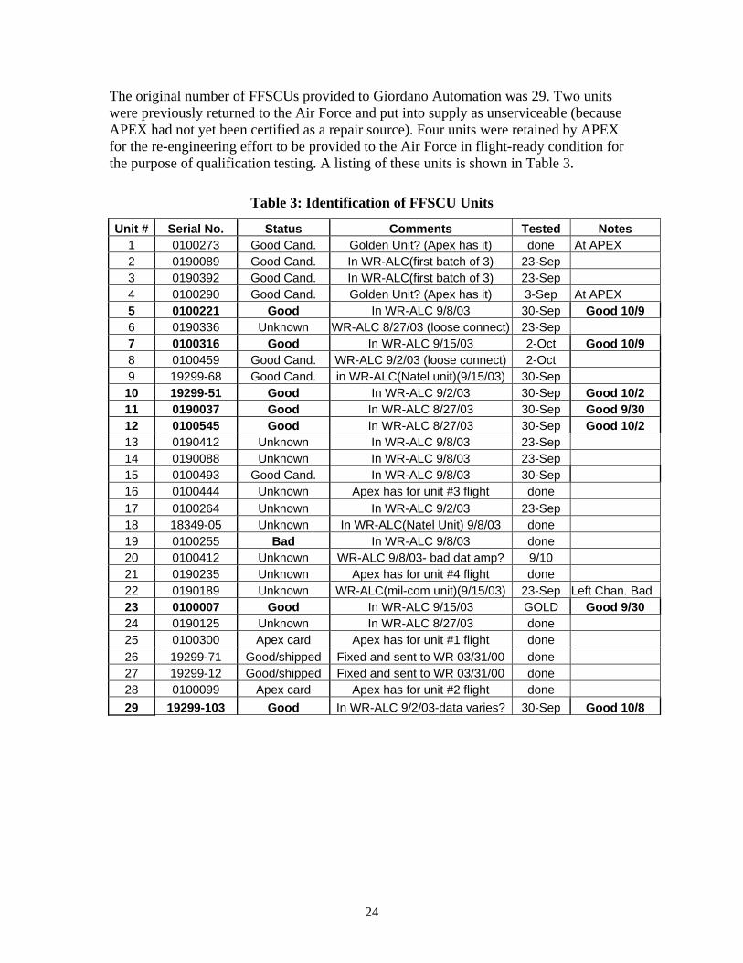
The original number of FFSCUs provided to Giordano Automation was 29. Two units were previously returned to the Air Force and put into supply as unserviceable (because APEX had not yet been certified as a repair source). Four units were retained by APEX for the re-engineering effort to be provided to the Air Force in flight-ready condition for the purpose of qualification testing. A listing of these units is shown in Table 3.
Table 3: Identification of FFSCU Units
Unit # Serial No. Status Comments Tested Notes 1 0100273 Good Cand. Golden Unit? (Apex has it) done At APEX 2 0190089 Good Cand. In WR-ALC(first batch of 3) 23-Sep 3 0190392 Good Cand. In WR-ALC(first batch of 3) 23-Sep 4 0100290 Good Cand. Golden Unit? (Apex has it) 3-Sep At APEX 5 0100221 Good In WR-ALC 9/8/03 30-Sep Good 10/9 6 0190336 Unknown WR-ALC 8/27/03 (loose connect) 23-Sep 7 0100316 Good In WR-ALC 9/15/03 2-Oct Good 10/9 8 0100459 Good Cand. WR-ALC 9/2/03 (loose connect) 2-Oct 9 19299-68 Good Cand. in WR-ALC(Natel unit)(9/15/03) 30-Sep 10 19299-51 Good In WR-ALC 9/2/03 30-Sep Good 10/2 11 0190037 Good In WR-ALC 8/27/03 30-Sep Good 9/30 12 0100545 Good In WR-ALC 8/27/03 30-Sep Good 10/2 13 0190412 Unknown In WR-ALC 9/8/03 23-Sep 14 0190088 Unknown In WR-ALC 9/8/03 23-Sep 15 0100493 Good Cand. In WR-ALC 9/8/03 30-Sep 16 0100444 Unknown Apex has for unit #3 flight done 17 0100264 Unknown In WR-ALC 9/2/03 23-Sep 18 18349-05 Unknown In WR-ALC(Natel Unit) 9/8/03 done 19 0100255 Bad In WR-ALC 9/8/03 done 20 0100412 Unknown WR-ALC 9/8/03- bad dat amp? 9/10 21 0190235 Unknown Apex has for unit #4 flight done 22 0190189 Unknown WR-ALC(mil-com unit)(9/15/03) 23-Sep Left Chan. Bad 23 0100007 Good In WR-ALC 9/15/03 GOLD Good 9/30 24 0190125 Unknown In WR-ALC 8/27/03 done 25 0100300 Apex card Apex has for unit #1 flight done 26 19299-71 Good/shipped Fixed and sent to WR 03/31/00 done 27 19299-12 Good/shipped Fixed and sent to WR 03/31/00 done 28 0100099 Apex card Apex has for unit #2 flight done 29 19299-103 Good In WR-ALC 9/2/03-data varies? 30-Sep Good 10/8
25
Figure 14: FFSCU Design Information provided by APEX
26
3.3 TEMS IEPU LRU Depot Test Program Set (Re-directed) Giordano Automation was tasked to develop an LRU test program for the IEPU in March 2003. At that time, Giordano Automation commenced a number of activities related to the development of the test program. In early July, the Air Force requested that we stop working the IEPU TPS. At that time, Giordano Automation was re-directed to direct 70K to support a funding shortfall in UDAS functional testing, including 40K to fund Lockheed for the use of the CSFDR hotbench for UDAS functional testing. Prior to this effort being halted, Giordano Automation successfully integrated the Diagnostician into the BRAT software environment using the BRAT SDS (Software Development Station). The Diagnostician runs as a separate process and communicates with the TBASIC TPS code via file I/O. A TBASIC user library was created that encapsulated all the communication between the TPS program and the Diagnostician. This library fits directly into the TPS Style guidelines for programming on a BRAT station. Additionally, using the BRAT TPS Style guide and the TBASIC Diagnostician Library described above a shell TPS program was created for 4 TEMS SRUs. These include the 091300, 091200, 091250, and the 091150 UUTs, which are currently hosted on the MATE390 System. These shell programs contain all the diagnostic logic, the diagnostic knowledge base, and a stub function for each functional and diagnostic probe test needed. This shell program was executed on the SDS in simulation mode for each of the SRUs. During execution, dummy test results were entered using the stub functions, which prompt the user for pass/fail condition. We were able to verify the correct diagnostic flow and callouts for each SRU. What remains to be done for these TPSs is to replace the stub functions with real test functions to perform the corresponding test and measurements. 3.4 AGETS 3.4.1 AGETS Long Term Sustainment Study The AGETS Long Term Sustainment Study was completed and a Final Report with short term and long term recommendations was provided to the Air Force. A briefing on the study and its results was prepared and presented to the AGETS IPT meeting and AGETS USER meeting. The study resulted in Air Force implementation of the majority of the short term recommendations. The long term studies resulted in an action plan by the program office to create and implement an AGETS sustainment roadmap for the future. The requirements for the DAA Assembly was addressed in the adoption and incorporation of the ADETS Engine test directives into the AGETS Roadmap and is subsequently maintained and controlled through the AGETS program office and the AGETS MASTA support group at WRALC. Subsequent hardware modifications are defined with the AGETS roadmap.
27
3.4.2 AGETS Relay Study The AGETS Relay Study was completed, and the results were documented in a AGETS Long Term Sustainment Study Report as a series of findings and recommendations related to AGETS Relays. This was provided to the Air Force. A briefing on the study and its results was prepared and was presented to the AGETS User conference. The relay recommendations resulted in the implementation of the relay upgrade prototype. A relay prototype has been designed, fabricated and delivered to the Air Force and is undergoing testing. 3.4.3 AGETS System Upgrades Four upgrade kits as defined by AF TO 33D4-6-690-519 were delivered. One kit was installed in the Engine Test System (AGETS) at WR-ALC. Another kit was installed in the Engine Test System (AGETS) at OK-ALC. The other two kits were delivered to Kadena AFB in Okinawa. Key component sparing was included as required by the Air Force. 3.4.4 AGETS Software Support (OnBoard Software Subcontract) Giordano Automation subcontracted AGETS software support to OnBoard Software. During the March 2004 reporting period OnBoard completed the Installation and Acceptance of the Rev 3 Software Revision. Onboard delivered the Software Test Report, Version Description Document and the Revised Software Specification for the AGETS Test Software. The CPINS and supporting documentation were released to the WRALC Software Control Center.
28
3.5 UDAS Test at LM Aero The UDAS prototype was tested at the F-16 Crash Survivable Flight Data Recorder (CSFDR) Hot Bench at Lockheed Martin Aerospace in Ft. Worth, Texas. The testing was completed during the first two weeks of December 2003. The tests were witnessed by LM Aero and F-16 representatives, and were successfully concluded. The input flight profiles were properly processed by UDAS. These tests completed the initial phase of UDAS development on the LM hot bench and verified that the UDAS open architecture is feasible. The tests also demonstrated that the F-16 card stack will interface with the aircraft system.
29
3.6 IEPU TPS TASK RE-DIRECTION During the reporting period of December 2003, a redirection of the IEPU task was received. The scope of the redirection was provided in a revised statement of work from the program office and was accepted. These tasks are described below. 3.6.1 FFSCU Emergency Repair for KC-135 The FFSCU TPS was completed and brought into the production line on a high-priority basis. The result of this effort allowed GAC and the Air Force to put an on-going supply of units back into service. The depot has been able to support specific MICAPS that have occurred by using unknown “F” condition units and screening to provide flight-worthy assemblies. This activity has successfully resulted in responding to an immediate need and providing short term response in supporting the demand for improved test approaches and organic depot support to accomplish a short term need at a significant savings to the Air Force. 3.6.2 Mishap Investigation Giordano Automation participated in an analysis related to a TEMS Mishap investigation of an event associated with the A-10 engine. The analysis was performed in coordination with the TEMS PM and OO-ALC Engine Management personnel, A-10 SPD, and WR-ALC organizations to perform this investigation. In review on the subject investigation with respect to TEMS operations, the following steps were taken: 1. Coordinated analysis with TF-34 Engine Management organization at OC-ALC 2. Analyzed reported engine conditions associated with mishap 3. Correlated engine conditions to TEMS parameters 4. Correlated MALTRAN criteria across TEMS Engineering Data (completed) 5. Verify consistency of MALTRAN criteria across TEMS CPIN, Engineering Data and TO (on-going) With respect to issues that a serious engine event could have occurred without producing a MALTRAN event, the following observations and conclusions were offered:
1. The TEMS system and associated algorithms for declaring an event were generated many years ago. Severe memory limitations at the time the system was developed are a likely reason. Any updates to the TEMS system that includes additional memory should include continuous monitoring and recording of key engine parameters.
2. The TEMS algorithms were designed to trigger Level 1 and Level 2 MALTRAN events without producing an inordinate number of false alarms. There is a traditional dilemma in establishing tolerance limits and ranges to produce true alerts versus false alarms.
30
3. The TF-34 Engine Management organization at OC-ALC is conducting a detailed review of the TEMS algorithms starting in OCT 04. The TEMS Program Office will participate in this review. The review represents the first time since the TEMS system was developed that a comprehensive review of the algorithms has been conducted. Since the engine has gone through various updates over time, this review is past due. GE, the engine manufacturer, will participate in this review.
4. The TEMS program office is working with the A-10 SPD to plan for modernization of the TEMS system. One goal of the modernization is to provide more memory so that more data can be collected. Another goal would be to modernize the TEMS software such that the TEMS algorithms are more flexible, robust and object-oriented. The definition of the triggering of MALTRAN events, however, will remain the responsibility of the engine and aircraft management organizations.
5. A working group consisting of the A-10 SPD, the TF-34 Engine Managers and the TEMS Program Manager must be established to ensure the near-term and long-term update and growth requirements for TEMS in particular and also data acquisition on the A-10 aircraft in general.
6. A better working relationship between the A-10 SPD, the TF-34 Engine Managers and the TEMS program manager must be established. The A-10 SPD currently has data acquisition plans and efforts in place that are not well-coordinated with the TEMS or TF-34 cognizant organizations.
7. Since the TEMS program office primary goal is to support the end user of the TEMS system, inputs should be strongly encouraged and an on-going dialogue regarding concerns and needs with respect to the TEMS system.
Continuing Sustainment actions include:
1. Complete the correlation across the CPIN, engineering data and the TO with respect to TEMS algorithms.
2. Meet with A-10 SPD regarding concerns related to engine and aircraft data acquisition and current efforts to update the TEMS system.
3. Participate in TF-34 algorithm review, and be prepared to coordinate and implement any required changes to TEMS operations that result from this review.
3.6.3 Tear-down & Quote Giordano Automation participated in the response to the A-10 SPD request for a tear-down and quote for a bad actor IEPU. Issue: The issue is the perception that the IEPU follows suit with the EPU when it comes to excessive failures for erroneous vibration detection failures. The request to perform a formal Tear Down Report (TDR) for the TEMS/ADR IEPU last removed from A-10 aircraft 80-0237 at New Orleans is to determine the exact failure mode within this asset. The SPD feels the source of failure is aircraft related, relatively intermittent, and causing the IEPU(s) to fail. Current facilities used for the EPU (IATS) have not been fully
31
successful at discovering erroneous vibration problems. This has long plagued the A-10 community. The investigation with the goal to integrate the Plan of Action with Long term IEPU Support Planning included the following:
• Investigate the problem and associated previous related problems and activities related to the resolution of the high vibration anomaly (Code 37 Hits) • Develop a Plan of Action for resolving the issues associated with the IEPU • Coordinate a strategy with the TEMS PM and ES • Coordinate with NGC • Coordinate with the depot on their efforts associated with EPU refurbishment • Assist in implementing the Plan of Action
3.6.4 Loop Tester Study of Best Alternative to Hosting of AIS Functions Giordano Automation has been continuously involved in the engineering analysis of the software and sustainment issues associated with the TEMS AIS (Loop Tester). This is an aged tester whose functionality is critical to proper test, configuration and sell-off of TEMS EPUs. In accomplishing the definition and recommendations of the LOOP tester task, the following issues are addressed:
• Functions the loop tester performs and how the depot makes use the loop tester functions. Alternative approaches are feasible for these functions
• What other approaches exist for EPU initialization? • What are the field and depot issues associated with EPU initialization and data
download such that EPUs are returned to the depot as “unable to download.” • Functional and TEMS sustainment issues associated with the loop tester • Costs / benefits of these various approaches and recommended direction.
3.6.5 EPU Download Problem Investigation Giordano Automation participated in an investigation of the problems that A-10 field users are having related to EPU download in the field. As part of the study, we have participated in the definition and characterization of the problem being experienced in the field, as well as identification of the cause(s) of the problem, and recommend solutions that would resolve the problem. A field trip to Pope AFB was accomplished to bring known condition EPUs to the aircraft and participate in the study and resolution of this chronic condition. The results culminated in the reporting procedure, trip report and a series of tasks, procedures to be implemented and future recommendations to circumvent and alleviate this chronic and intermittent problem. A multi-pronged program has been defined and recommended and the tasks are being planned for FY04 and out-year implementation. The upload/download problem often seen in the field is not always an EPU problem. In addition to known vibration anomalies, and certain contamination issues, it seems to be generally a process and configuration issue. Many things can keep the software from
32
uploading and down loading correctly, including using CETADS on a unsupported platform, like windows 2000 or XP. The resulting reports highlight a series of Sustainment tasks that should be implemented to alleviate this condition.
33
4.0 APPENDIX A - List of Deliverables A001R Program Progress Report, para 4.7.1 Delivered monthly in accordance with contract requirements. A002R CFSR, para 4.7.2 Delivered monthly in accordance with contract requirements. A003R S&TR, Final Tech Report, para 4.1.1.3.4, 4.7.3 Final Technical Report contained herein. (4.7.3) Final AGETS Technical Report delivered October 2003 (4.1.1.3.4) A004R Presentation Material, para 4.7.4
Presentation Material delivered throughout contract and copies included in Monthly Progress Reports
A005R Revisions to Gov Docs, para 4.1.1.3.3.5, 4.1.2.1, 4.2.5, 4.2.6, 4.7.5 4.1.1.3.3.5 – Revisions to AGETS Programmer’s Manual delivered by OnBoard Software 4.1.2.1 – RAM card replacement never successfully flight tested. 4.2.5 – This task remained unfunded. 4.2.6 – This task performed by Frontline and deliverables were provided to the AF
4.7.5 – Updates were made to TEMS SRU TPI documents and delivered as part of the TPS documentation package.
A006R TIR, Tech Info Report (TIR), Analysis, para 4.1.1 Technical Report: Functional/In-Circuit Test Study, delivered to the Air Force: Dec 01 A007R TIR, Modification Implementation Procedures, para 4.1.2.2
Technical Report: Altering Configurations of the 091600 RAM card delivered to Air Force October 2000
A008R Presentation Material, 4.1.2.4 Presentation Material delivered to Air Force and included in Monthly Progress Reports A009R TIR, Circuit Card ID, para 4.2.4 This task performed by Frontline and deliverables were provided to the AF A010R TIR, Adjustment Recommendations, para 4.2.5 This task remained unfunded.
34
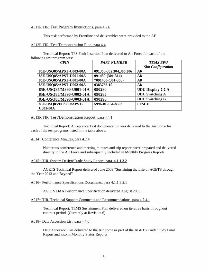
A011R TIR, Test Program Instructions, para 4.2.6 This task performed by Frontline and deliverables were provided to the AF A012R TIR, Test/Demonstration Plan, para 4.4 Technical Report: TPS Fault Insertion Plan delivered to Air Force for each of the following test program sets:
CPIN PART NUMBER TEMS EPU Slot Configuration
85E-USQ85/APST-U003-00A 091350-302,304,305,306 A6 85E-USQ85/APST-U001-00A 091450-(301-314) A8 85E-USQ85/APST-U001-00A *091460-(301-306) A8 85E-USQ85/APST-U002-00A 9383755-10 A8 85E-USQ85/M390-U001-01A 090280 UDU Display CCA 85E-USQ85/M390-U002-01A 090285 UDU Switching A 85E-USQ85/M390-U003-01A 090290 UDU Switching B 85E-USQ85/FFSCU/APST-U001-00A
5996-01-154-8593 FFSCU
A013R TIR, Test/Demonstration Report, para 4.4.1 Technical Report: Acceptance Test documentation was delivered to the Air Force for each of the test programs listed in the table above. A014+ Conference Minutes, para 4.7.4
Numerous conference and meeting minutes and trip reports were prepared and delivered directly to the Air Force and subsequently included in Monthly Progress Reports.
A015+ TIR, System Design/Trade Study Report, para, 4.1.1.3.2
AGETS Technical Report delivered June 2003 “Sustaining the Life of AGETS through the Year 2013 and Beyond” A016+ Performance Specifications Documents, para 4.1.1.3.2.1 AGETS DAA Performance Specification delivered August 2003 A017+ TIR, Technical Support Comments and Recommendations, para 4.7.4.1
Technical Report: TEMS Sustainment Plan delivered on iterative basis throughout contract period. (Currently at Revision 6)
A018+ Data Accession List, para 4.7.6
Data Accession List delivered to the Air Force as part of the AGETS Trade Study Final Report and also in Monthly Status Reports