34
Turbine Flowmeter User Manual

Turbine Flowmeter
User Manual
CONTENT
I. General......................................................................................................................1
1.1 Introduction.....................................................................................................1
1.2 Product Features........................................................................................... 1
1.3 Working Principle...........................................................................................2
1.4 Major Technical Performance......................................................................3
1.5 Overall Dimension......................................................................................... 5
II. Installation Requirements......................................................................................7
III. Operation.................................................................................................................8
3.1 Wiring...............................................................................................................9
3.1.1TB3WE Three-Wire System Electric Wiring.....................................9
3.1.2 TB2WE Three-Wire System Electric Wiring................................. 10
3.2 Local LCD Operation Instruction...............................................................11
3.2.1 User Menu Operation....................................................................... 11
3.2.2 User Data Setting..............................................................................11
Appendix.....................................................................................................................15Trouble Shooting.............................................................................................16
MANUALE OPERATIVO MISURATORE DI PORTATA A TURBINA SMERI srl

1
I. General
1.1 Introduction
LWGY turbine flow meter consists of turbine flow sensor and display instrument and it is
made by us using foreign state-of-the-art technologies, which is an ideal gauge for
measuring of liquid flow.
The flow meter is characterized by simple structure, high precision and easy installation
and repair. The product may be used in a wide range of industries, including oil industry,
chemical industry, metallurgy, water supply, paper-making, environment protection and
food industry.
It is applicable for use in closed pipes to measure flow of liquid which will not erode
stainless steel (1Cr18Ni9Ti), 2Cr13, Al2O3 and hard alloy and is free of impurities such as
fiber and granules. If this product is used in association with display instruments with
special functions, it can be used for purpose of automatic definite quantity control and
alarming in case of excessive amount.
1.2 Product Features
1. The sensor is of hard alloy bearing thrust type, which may guarantee the precision
and improve the wear resistance performance as well.
2.Simple and firm structure, easy for installation and dismantling.
3.Wide range of measuring with very low lower flow velocity limit.
4.Small loss of pressure,fine repeat ability and high precision.
5.High resistance to electromagnetic interference and vibration.
MANUALE OPERATIVO MISURATORE DI PORTATA A TURBINA SMERI srl

2
1.3 Working Principle
When liquid flows through the casing of sensor, the impulse of fluid will provide the blade
with a rotation moment as there is an angle between the blade of impeller and the flow
direction. The blade will rotate as the friction moment and the fluid resistance are
overcome and it will reach a stable speed when the moments are at balance. Under
certain conditions, the rotation speed of blade will be in direct proportion to the flow
velocity. Due to the magnetic conductivity of blade, when located in the magnetic field
generated by signal detector (made of permanent magnet steel and coils), the rotating
blade will cut the magnetic lines and periodically change the flux through the coil, thereby
inducing electrical impulse signals at both ends of the coil. The induced signals, after
amplified and rectified by amplifier, will form a continuous rectangular impulse wave with
certain amplitude which may be remotely transmitted to display instrument indicating the
instant flow and the cumulative flow of fluid. Within a certain range of flow, the impulse
frequency f is in direct proportion to the instant flow of fluid flowing through the sensor,
which is shown in the equation below:
kfQ 3600
Wherein:
f- Impulse frequency [Hz];
k- Instrument factor of sensor [1/m3], which is given by checklist. If [1/L] is used as the unit,
the equation will be: kfQ 6.3
Q- Instant flow of liquid (in operation) [m3/h];
3600- Conversion factor.
Instrument factor of each sensor will be filled out in verification certificate by the
manufacturer. The instant flow and cumulative flow will be displayed when the value of k is
loaded into associated display instrument.
MANUALE OPERATIVO MISURATORE DI PORTATA A TURBINA SMERI srl

3
1.4 Major Technical Performance
1. Nominal drift diameter:(4~200)mm, refer to Table 1 for the basic parameters;
2. Medium temperature:(-20~80)°C; Split type (-20~120) °C;
High temperature type please noted before ordering.
3. Ambient temperature:(-20~70)°C;
4. Precision: ±0.5%, ±1%;
5. Detector signal transmission wiring system: three-wire voltage impulse (three-core
shield wire);
6. Power supply:
1) TB3WE Three Wire
External Power:12~24VDC/30mA(-20%~+15%),if no output can be as low as 6V
Battery:Lithium battery 3.6V(2/13Ah)/0.4mA
2)TB2WE Two Wire
12~24VDC/4-20mA(-20%~+15%)
7. Transmission distance: the distance between the sensor and the display instrument
may be as far as 1000m;
8. Local display power supply: 3.6V (Lithium battery, may be used continuously for more
than 3 years);
9. Display mode: local LCD displays instant flow and cumulative flow;
10. Output Signal
a)TB3WE Three Wire
1)Pulse Output:High level voltage amplitude≥5V, low level<0.5V
2)Three sire 4-20mA linearity correction current output(need ground wire)(load
resistance≤800Ωat 24V)
3)RS485 communication:flowmeter with RS485 interface, communication
distance≤1200mm.
b)TB2WE Two Wire
1) Two wire 4~20mA linearity correction current output(need ground wire)(load
resistance≤600Ωat 24V)
MANUALE OPERATIVO MISURATORE DI PORTATA A TURBINA SMERI srl

4
2) Origin Pulse output:High level≥5V(power supply voltage-1V),Low level<0.5V
Table 1
LWGY□ □□□ □ □ □ Description
Type
N Sensor with Pulse(without local display)A 4-20mA Transmitter (without local display)B Local display, powered by 3.6V battery;C Local display with 4~20mA, powered by DC24V;
RS485 With RS485,local display type, DC24V;
HART With HART,local display type, powered by DC24V;
Nominal diameter
4
Normalflow rangem3/h
0.04~0.25
Extendedflow rangem3/h
0.04~0.46 0.1~0.6 0.06~0.610 0.2~1.2 0.15~1.515 0.6~6 0.4~820 0.8~8 0.45~925 1~10 0.5~1032 1.5~15 0.75~1540 2~20 1~2050 4~40 2~4065 7~70 3.5~7080 10~100 5~100100 20~200 10~200125 25~250 12.5~250150 30~300 15~300200 80~800 40~800
Explosion protectionNot marked, without explosion protection
B Explosion protection type
Precision classA Precision: Class 0.5B Precision: Class 1.0
Turbine typeA Normal flow rangeB Extended flow range
Note:Sensors with pipe diameter of DN4~DN40 are of thread connections with maximum operating pressure of6.3Mpa.Sensors with pipe diameter of DN50~DN200 are of flange connections with maximum operating pressure of2.5Mpa.Sensors with pipe diameter of DN4~DN10 are provided with front and rear straight pipe sections and filters.Please specify when placing an order if flange connections are required for pipe diameter of DN15~DN40.Please specify when placing an order for high pressure type and special requirements.
MANUALE OPERATIVO MISURATORE DI PORTATA A TURBINA SMERI srl

5
1.5 Overall Dimension
The installation types of sensors vary according to specifications, which may be
connected either by thread or flange. The installation types are shown in Fig. 1, Fig. 2,
Fig.3, Fig. 4 and Fig. 5. The installation dimensions are shown in Table 2.
Fig. 1 Structure of DN4~DN10 sensor and installation dimension diagram
Filter 2. Front straight pipe section 3. Impeller 4. Preamplifier 5. Casing 6. Rear straight
pipe section
Fig. 2 Filter structure diagram
Clamp ring 2. Bolts 4×14 3. Washer 4. Sealing washer 5. Steel wire 1Cr18Ni9Ti-0.8×2.5
6. Filter screen 7. Base
MANUALE OPERATIVO MISURATORE DI PORTATA A TURBINA SMERI srl

6
Fig. 3 Structure of DN15~DN40 sensor and installation dimension diagram
Casing 2.Front guide part 3.Impeller 4.Rear guide part 5.Preamplifier
Fig. 4 Structure of LWGY—50~200 sensor and installation dimension diagram
Ball bearing 2.Front guide part 3.Expansion ring 4.Casing 5.Preamplifier
6.Impeller 7.Bearing 8.Shaft
MANUALE OPERATIVO MISURATORE DI PORTATA A TURBINA SMERI srl

7
II. Installation Requirements
Flow meter may be installed horizontally or vertically. In the latter case the fluid shall be
flowing from downward and fulfill the pipe to avoid bubbles; the flowing direction of liquid
shall be consistent with the direction indicated by the arrow on casing of the sensor; as far
as front and rear straight pipe sections are concerned (see Fig. 6), at upstream there shall
be front straight pipe section at least 10 times of nominal drift diameter in length and at
downstream no less than 5 times of nominal drift diameter in length. The internal wall of
pipe sections shall be smooth and clean, free of defects such as indent, fouling and
peeling. The pipe axis of the sensor shall be aligned with that of the neighboring pipe and
the washers used for connection and sealing may not be embedded into depth of the pipe
cavity; the sensors shall be kept away from foreign electric field and magnetic field,
effective shielding measures shall be taken in case of necessity to avoid external
interference.
In order that the normal transfer of liquid will not be affected by maintenance, it is
recommended that bypass pipes be installed at position of sensor.
In case of open air installation, water proof measures shall be taken for purpose of
amplifier and plug of the sensor. The wiring between sensor and display instrument is
shown in Fig. 5.
When fluid contains impurities, filter shall be additionally installed. The number of filter
screen meshes is determined in accordance with the flow and impurity, normally 20 to 60
meshes. When fluid is mixed with free gases, gas eliminator shall be additionally installed.
The complete pipe system shall be well sealed. The user shall fully understand the
erosion nature of the measured medium to protect the sensor from being eroded.
Fig. 6 Requirements on straight pipe section for installation of flow meter
MANUALE OPERATIVO MISURATORE DI PORTATA A TURBINA SMERI srl

8
One90°elbow
Two 90°elbowsfor twoplanes
Concentricexpander
Controlvalvehalf-open
Concentricshrinkagewideopenvalve
Two 90°elbowsfor oneplane
III. Operation
◆ When sensor is used, the liquid to be measured shall be clean and free of impurities
such as fiber and granules.
◆ When sensor is used, it shall be at first slowly filled with liquid, then open the outlet
valve (which should be installed behind the flow meter). It is prohibited to render the
sensor under impact of high-velocity fluid when it is not filled with liquid.
◆ The maintenance interval for sensor is in general half a year. In case of maintenance
and cleaning, attention shall be paid not to damage the parts in the measuring cavity,
particularly the impeller. During assembly, watch carefully the positional relation between
guide part and impeller.
◆ When the sensor will be out of service for a long time, the internal liquid shall be
cleaned. After dried, the sensor shall be provided with protection sleeves at both ends to
protect against dust and it shall be placed in dry conditions for storage.
◆ The associated filter shall be cleaned on regular basis and the internal liquid shall be
20×D 5×D 5×D40×D
5×D5×D25×D 50×D
25×D 5×D5×D15×D
MANUALE OPERATIVO MISURATORE DI PORTATA A TURBINA SMERI srl
9
cleaned when it is out of service for a long time. Similar to sensor, the filter shall also be
provided with dust protection and stored in dry conditions.
◆ The transmission wire of sensor may be overhead or buried (iron bushing shall be
provided in the latter case).
◆ Prior to installation of sensor, the connection thereof with display instrument or
oscilloscope shall be finished. Then switch on the power, blow the impeller with mouth or
move the impeller with hand to make it rotate quickly, see if there is any reading. Install the
sensor if there is reading. In case of no reading, the related sections shall be inspected to
eliminate any fault.
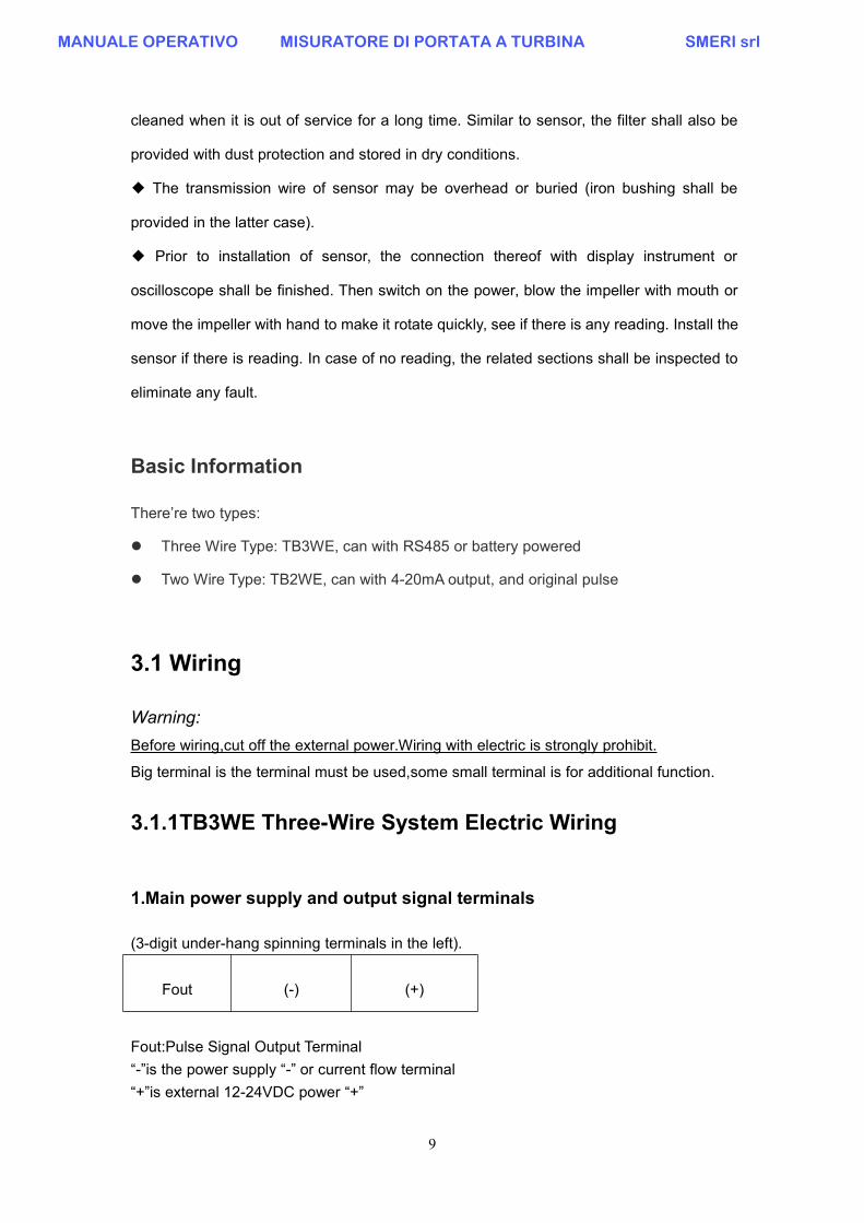
Basic Information
There’re two types:
Three Wire Type: TB3WE, can with RS485 or battery powered
Two Wire Type: TB2WE, can with 4-20mA output, and original pulse
3.1 Wiring
Warning:Before wiring,cut off the external power.Wiring with electric is strongly prohibit.
Big terminal is the terminal must be used,some small terminal is for additional function.
3.1.1TB3WE Three-Wire System Electric Wiring
1.Main power supply and output signal terminals
(3-digit under-hang spinning terminals in the left).
Fout (-) (+)
Fout:Pulse Signal Output Terminal“-”is the power supply “-” or current flow terminal“+”is external 12-24VDC power “+”
MANUALE OPERATIVO MISURATORE DI PORTATA A TURBINA SMERI srl

10
When “+” “-”connect (or battery type power on),pulse output from “Fout”.
2.Auxiliary Wire(small terminal)
The three-wire between main terminal and auxiliary terminal are pulse output switch.If insert into the outside F0,there will be pulse output.If insert into the inside NC,then no pulse output.For two wire current type,only insert outside F0 while testing.If use current,must insert inside NC to disconnect pulse output. Or else,the current will notbe accuracy.
3.Battery Powered Type
+3V6 3V6- B- A+1).Battery Wiring(the right side 1 and 2 in small terminal)+3V6: Connect 3.6V battery “+”3V6-: Connect 3.6V battery “-”
2)Communication Wiring(the left side 3 and 4 in small terminal, if without RS485,no terminal here)B-:Connect RS485 “B-”A+:Connect RS485”A+”
3.1.2 TB2WE Two-Wire System Electric Wiring
1.Main power supply and output signal terminals
Fout (-) (+)
“-”:4-20mA output terminal“+”:15-24V power “+” terminal
“+” Connect with +24V external power, current output from “-” to computer/sampleresistance of the display. After flow through some load resistance like sampleresistance,then back to power “-”.
2.Auxiliary Wire(3-digit small terminal)4-20mA current output type with no auxiliary small terminals.Fout: Pulse output terminalWhen “+” “-” connect with external power then work,pulse output from “Fout”.
MANUALE OPERATIVO MISURATORE DI PORTATA A TURBINA SMERI srl

11
The three-wire near main terminal are pulse output switch.If connect to the outside F0,there will be pulse output.If connect to the inside,then no pulse output.For two wire current type,only insert outside while testing.If use current,must insert inside NC to disconnect pulse output. Or else,the current will notbe accuracy.This pulse is origin pulse without any modify,usually use while doing calibration; Outputsignal is the open-collector output include 2K7 pull-up resistor.
System wiring please refer to the appendix “TB3WE three wire” and“TB2WE Two Wire”.
3.2 Local LCD Operation Instruction
3.2.1 User Menu Operation
(1)Working Menu
After power-on,meter will be self-checking first,after then it will enter into LCD(figure1 )working display status.
Chart 1 TB2/3WE working screen (Figure One)
The first line: High level of Accumulative flow; 5 fixed integer part number. If no,it’ll displayas “0”.The second line: Low level of Accumulative flow;3 decimals part number after the 5 fixedinteger number. The unit is the same with instant flow non-time part.
The third line:Instantaneous Flow; 5 or 6 integers and automatic keep 2 or 1 decimals.The unit can be set.
Press “<” or “+” to change the screen from Working Screen 1 and 2
XXXXX
XXXXX.XXXm3
XXXX.XXm3/h
MANUALE OPERATIVO MISURATORE DI PORTATA A TURBINA SMERI srl

12
Chart 2 TB3WE Three-wire System working screen (Figure Two,Sub Screen)
Chart 3 TB2WE Three-wire System working screen (Figure Two,Sub Screen)
From Up to Down:The first line:Temperature value setting for temperature compensationcalculation,shows”T≡999.9℃”,reserving 1 decimal.The second line:Pressure value setting for pressure compensationcalculation,,shows”P≡99999.99kPa”,reserving 2 decimals.The third line:For TB3WE is frequency value.
For TB2WE is frequency value(left side) and current output(right side)
The four line:password entering set state.Press the enter key of “<”(about 1.2seconds) to enter password initial input state.Press the key of “+”(about 1.2seconds) to cancel entering state and return to figure twoSubsidiary LCD.
Press “+”key in the input state to change the value of cursor circularly.Press the shift key“<” to change the position of input cursor.Press “<”key (about 1.2seconds) at the input state to submit the password.If right,enter to menu.if incorrect,return to initial input state.
T=xxx.xx ℃
P=xxx.xxkPa
F=xxx.xxHz
Enter pass word:xxxx
T=xxx.xx ℃
P=xxx.xxkPa
xxx.xxHz xx.xxmA
Enter pass word:xxxx
MANUALE OPERATIVO MISURATORE DI PORTATA A TURBINA SMERI srl

13
Chart 4 Password Initial Input State
Password:User menu password 2010
3.2.2 User’s Data Setting
1.Input operationIn the input state:Pree “+”key in a long time to exit the input state.Pree “<”key to confirm and save the input.Press “+”key in the input state to change the value or symbol of cursor circularly.Press “<”key to move the current cursor one position towards the right.Max.8 digits inputting is allowed.(including the symbol,decimal).
2.Menu OperationIn the menu browse:Press “+” key for page down;Press“<”key for page up;Long Press“<”key for entering into the sub-menu;Long press “+” key for returning to the working screen figure 2;
In the sub-menu,long press “+” key to quit out;long press “<”key to enter into modifiedstate;In the modified state,press “+” key for downward selecting;press “<”for upwardselecting;long press “<”key for confirmation and saving.
Attention:When the parameter setting,it should long press “<”key for saving thedisplaying.Otherwise,the setting is invalid.
User Parameter Setting Menu
Sub-menu Series#
Display ofmenu
Definition Alternative options or range of value
1Flow Unit
select
Flow Unit
select
(default 0)
0:m3/h 1:m3/m
2:l/h 3:l/m
4:t/h 5:t/m
T=xxx.xx ℃
P=xxx.xxkPa
F=xxx.xxHz
Enter password:xx
MANUALE OPERATIVO MISURATORE DI PORTATA A TURBINA SMERI srl

14
6:kg/h 7:kg/m
2Algorithm
Selection
Algorithm
Selection
(default 0)
00:Conventional Volume flow
01:Conventional mass flow
02:Volume flow of conventional gases
03:Mass flow of conventional gases
3Flow
Coefficient
Flow
Coefficient
(default 3600)
Set the meter coefficient with the unit of P/m3
4Maximum
Output Flow
Max. Flow
(default 1000)
When the meter outputs 4~20mA analog signal, must set the
value and the value cannot be zero,the unit should be
accordance with the flow unit.
5Density
setting
Density setting
(default 1.0)
When Algorithm Selection is setting to mass flow(01,03),it must
set this item,the unit is kg/m3
6Temperatur
e Setting
Temperature
Setting
(default 0.0)
Setting the temperature calculated value,when choose
02,03,04,06 algorithm,it must set this item,the unit is Celsius
degree.
7
Absolute
pressure
setting
Gas Absolute
pressure set
(default
101.325)
Setting the absolute pressure of gas,when choose 02,03
algorithm,it must set this item,the unit is Kpa.(when vacuum is
0.0,it will cause the flow is 0)
8Low flow cut
off
Set percentage
of resection
pulse input
(Default 1%)
The value is between 0~100
9485
Address
Set RS485
communication
No.
(Default 1)
For three-wire system TB3WE only.The meter uses RS485
communication should set this item,and should not equal to
other equipment in the same system,the range is 0~255.
10Damping
time
Set current
output
damping time
(Default 4s)
Setting current and displaying damping time,it is for avoiding the
current’s fluctuation too big along with the flow rate.The range is
2~32.
11Reset
Cumulant
Reset
cumulantIf need to Reset cumulant,choose YES and press “E” key.
MANUALE OPERATIVO MISURATORE DI PORTATA A TURBINA SMERI srl

15
Appendix
MANUALE OPERATIVO MISURATORE DI PORTATA A TURBINA SMERI srl

16
Trouble Shooting
Trouble Analyse
1There’s liquid flow in the pipe,but the instantflow on the flow meter is 0
1.Check the wire connection is all correct or not2.Inside parameters are changed3.Signal collection coil is broken, signal can not transmitcorrectly.In this case,even there’s liquid flow, coil cannot transmit signal to the display part.Impeller is stuck by something,check the impeller.
2There’s no liquid flow through, but there’sflow display on the flow meter
1.Pipe has strenuous vibration, suggest to do take somevibration damping measures.2.Flow meter grounding well or not.3.There’s magnetic field interference, for example:frequency converter, electrical machine, magnetic valveor others. f there’s 50HZ power frequency interference,itmay influence the normal work of the flow meter. Powerfrequency interference calculation Q=3600f/k(f=50HZ,K= flow meter factor), After calculation,you cancheck if there’s power frequency interference or not.In this case, suggest to change installation location.4.The stop valve on the pipe is not fully closed. Checkthe valve.
3Flow meter work normally, but the measuredvalue is not accuracy.
1.Flow meter parameters inside has some problem.Check the parameters.2.Installation pipe can not reach the requirement, mayhave gas inside or high viscosity. In this case,pls followthe user manual and installation instruction strictly.3.Inside flow meter may has some problem. In thiscase,pls take off the flow meter, and use mouth to blowair to the flow meter, impeller should work normally, ifabnormal,pls contact with us.
4intelligent turbine flowmeter work normally,local display work normally, but the currentoutput is not correct
1.Check the forth display of the parameters, to checkthe flow range in the flow meter is the same as thename plate or not.2.Flow meter current output chip is broken or not.
MANUALE OPERATIVO MISURATORE DI PORTATA A TURBINA SMERI srl

With Hart Electronics Manual
(Support temperature and pressure compensation)
Turbine Flow Meter
VT2W-XXAV2018-06-16
MANUALE OPERATIVO MISURATORE DI PORTATA A TURBINA SMERI srl
2
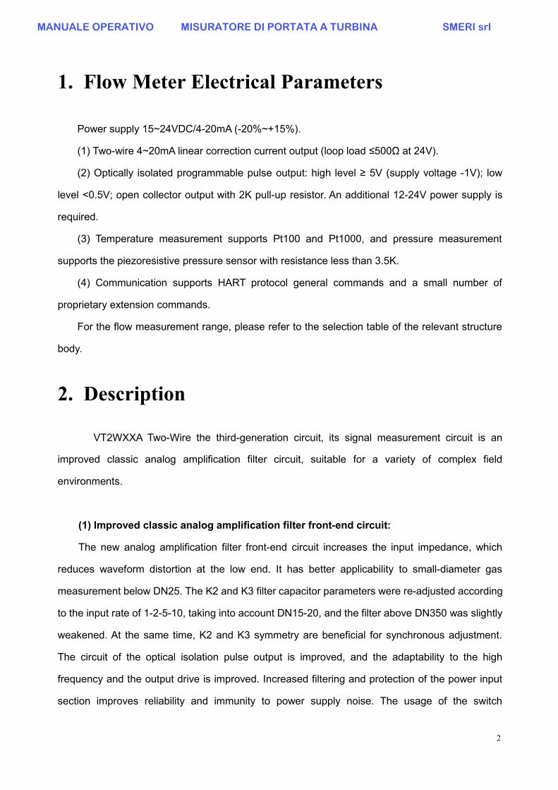
1. Flow Meter Electrical Parameters
Power supply 15~24VDC/4-20mA (-20%~+15%).
(1) Two-wire 4~20mA linear correction current output (loop load ≤500Ω at 24V).
(2) Optically isolated programmable pulse output: high level ≥ 5V (supply voltage -1V); low
level <0.5V; open collector output with 2K pull-up resistor. An additional 12-24V power supply is
required.
(3) Temperature measurement supports Pt100 and Pt1000, and pressure measurement
supports the piezoresistive pressure sensor with resistance less than 3.5K.
(4) Communication supports HART protocol general commands and a small number of
proprietary extension commands.
For the flow measurement range, please refer to the selection table of the relevant structure
body.
2. Description
VT2WXXA Two-Wire the third-generation circuit, its signal measurement circuit is an
improved classic analog amplification filter circuit, suitable for a variety of complex field
environments.
(1) Improved classic analog amplification filter front-end circuit:
The new analog amplification filter front-end circuit increases the input impedance, which
reduces waveform distortion at the low end. It has better applicability to small-diameter gas
measurement below DN25. The K2 and K3 filter capacitor parameters were re-adjusted according
to the input rate of 1-2-5-10, taking into account DN15-20, and the filter above DN350 was slightly
weakened. At the same time, K2 and K3 symmetry are beneficial for synchronous adjustment.
The circuit of the optical isolation pulse output is improved, and the adaptability to the high
frequency and the output drive is improved. Increased filtering and protection of the power input
section improves reliability and immunity to power supply noise. The usage of the switch
MANUALE OPERATIVO MISURATORE DI PORTATA A TURBINA SMERI srl

3
parameters is detailed in the attached table.
.
(2) Back-end flow calculation display circuit:
The new back-end main control board can select various measurement modes of
temperature and pressure from the Chinese/English prompt software menu, and improve the
temperature and pressure measurement accuracy. The data is processed by 12864 liquid crystal
display. The signal remote transmission circuit uses a 4-20 mA current output for two-wire system
and can add HART communication. There is also an isolated program-controlled pulse that can
be set to output the original signal frequency / / correction frequency / / 0-1KHZ linear frequency
output / / calibration engineering pulse / / upper or lower limit alarm.
1) Pulse output mode:
A. Signal frequency output: directly output the frequency of the probe detection signal
in real time.
B. Corrected frequency output: The frequency of the signal that is linearly corrected to
the average K value is corrected by the 5-point flow coefficient.
C. Frequency output: Output the converted frequency, and the frequency value is
linearly calculated according to the full-scale flow output 1000Hz.
D. Pulse count: Output the converted pulse. The number of pulses is calculated by
dividing the cumulative flow rate of each calculation cycle by the pulse equivalent. The
maximum output is only 1000 pulses per calculation period. If the actual number of
pulses in the calculation period is greater than 1000 , it will automatically accumulate to
the next calculation cycle output; the minimum is only allowed to output 4 pulses per
cycle. If the actual number of pulses in the calculation cycle is less than 4 pulses, it will
automatically accumulate to the next calculation cycle output; the effective level of the
output pulse Is high.
Note: The engineer needs to set the appropriate pulse equivalent factor based
on the current applicable object.
E. Upper limit alarm output—The alarm flow output alarm is higher than the set alarm,
and the alarm level transistor is turned on low.
F, lower limit alarm output - lower than the set alarm flow output alarm, the alarm level
MANUALE OPERATIVO MISURATORE DI PORTATA A TURBINA SMERI srl

4
transistor is low.
2) Current output:
The current output is linear 4-20mA and the output range is [4-22.4] mA. When the
instantaneous flow rate is less than or equal to the lower limit cut-off flow rate, or when
the signal frequency is 0, the output current is 4 mA; in other cases, the current output is
4 mA according to the cut-off flow rate, and the full-scale flow output 20 mA linearly
calculates the output current value, if the calculated current value exceeds 22.4 mA. , the
highest output is 22.4mA.
3) HART function:
The transmitter supports the HART function. The supported HART commands and
detailed descriptions can be found in the HART Communication chapter.
4) Use environment:
Due to the different ambient temperature, the display response speed of the LCD
screen also changes. If the LCD refresh rate is too fast at low temperatures, the display
may be unclear. Use the "Environmental Temperature" option in the engineer menu to set
the LCD screen to a refresh rate of -20 °C for use at low temperatures.
3. The Circuit Wiring
(1) Main power supply and output signal terminal block
(intermediate 2-position large hanging frame spin-type terminal)
○- ○+
“○- ” is the 4~20mA current output. “○+ ”: for 15~24V power supply
“○+ ”is connected to the +24V external power supply. The flow current output flows from the
MANUALE OPERATIVO MISURATORE DI PORTATA A TURBINA SMERI srl

5
“○- ”end to the sampling resistor of the computer or display meter, and flows back to the “-” end ofthe power supply after passing through the load such as the sampling resistor. These two
terminals are the wiring that must be used.
(2) Auxiliary wiring (3-bit low terminal)
V+ Fout Vss
“V+” is connected to the “+” terminal of the power supply (+12-24V); “Fout” is the pulse output
terminal; “Vss” is connected to the power supply “-” terminal.
This pulse output must be used with the main current loop powered. The output is a cut-off
optically isolated pulse, usually used when calibrating and collecting the frequency and pulse signal or
using the alarm function; the output signal is the collector with 2K pull-up resistor Open output
(3) Temperature and pressure wiring (6-bit small terminal)
TRH and TRL tap the Pt100 or Pt1000 to measure both ends of the platinum resistance.When Pt100 is selected, the double jumper on the temperature board should be shorted; whenPt1000, the double jumper on the temperature board should be disconnected.
The 200uA constant current source of the PIH and PIL taps the pressure sensor's IN+ and IN-,PVH and PVL tapped pressure sensing mV outputs VO+ and VO-. Generally, a siliconpiezoresistive sensor is used, which requires a bridge equivalent resistance of 1-3K5, azero-point positive bias output, and a sensitivity greater than a full-scale output of 25mV/mA.
4. Flow Meter Working Interface
The flow meter working interface includes two interfaces, one is the main interface and the
other is the auxiliary interface. Figure:
TRH TRL PIH PVH PVL PIL
MANUALE OPERATIVO MISURATORE DI PORTATA A TURBINA SMERI srl

6
Chart 1 main work interface
Chart 2 auxiliary work interface
Switch between the main interface and the auxiliary interface by pressing the ‘+/S’ left button
and the ‘</E’ button.
The left button is + and the page is turned down, and the long press is S to exit. Right click to
<turn up the page, long press to enter and confirm.
In the auxiliary interface, long press ‘</E’ left button to enter the password input state. The
user can press the ‘+/S’ key to select the password number that needs to be entered at the
current input position, and press the ‘</E’ key to move the input cursor position. After entering the
2-digit password, long press ‘</E’ to enter the function setting menu corresponding to the
password; in the password input state, long press ‘+/S’ to return to the auxiliary interface and
continue to update the displayed measurement value.
About the refresh rate of the main and auxiliary work interfaces. In the engineer menu, there
is the "Environmental Temperature" setting item. If -10 °C is selected, each cycle (about 2
seconds) is refreshed once; if -20 °C is selected, the main interface is refreshed every four
calculation cycles (about 8 seconds), the auxiliary interface is refreshed every 2 cycles (about 4
seconds).
MANUALE OPERATIVO MISURATORE DI PORTATA A TURBINA SMERI srl

7
5. Flow Meter Parameter Setting Menu
The flow meter menu includes a total of three groups: user menu, engineer menu, and
manufacturing menu. The engineer menu must have the expertise of the operator to set the menu
content. The manufacturing Menu is set and calibrated by the factory when the flow meter is out.
After the factory, the parameter setting must be modified under the condition of the
corresponding equipment. Otherwise, the flow meter will be incorrectly measured or
invalidated!
In the menu, long press the '</E' key to enter the parameter modification state of the selected
item. If it is a digital input type parameter, input the number by the '+/S' key, and the '</E' key
moves the input cursor position. After the input is completed, Press and hold the '</E' key to
confirm the input. The transmitter automatically updates the setting parameters and stores them.
If the parameter is the option type, select the item by '+/S' or '</E'. Press and hold the '</E' key to
confirm, the transmitter automatically updates the setup parameters and stores them.
User MenuIn the password input state of the auxiliary interface, enter the “22” password to enter the user
menu. The user menu structure is as shown below.
The various menu functions and parameters are as follows:
Menu No. Menu Display Meaning Selection or range of values
1 unit selectionflow unit selection
(default 0)
0 : m3/h Automatically add N whenalgorithm 21:m3/m2:l/h3:l/m4:t/h5:t/m6:kg/h7:kg/m
MANUALE OPERATIVO MISURATORE DI PORTATA A TURBINA SMERI srl

8
2 algorithm selectionalgorithm
selection(default 0)(Default 0)
0: Normal volume flow (whether gas or liquid)1: regular mass flow (condition density)2: standard gas volume flow3: Conventional gas mass flow rate (standarddensity)4: Saturated steam temperaturecompensation5: saturated steam pressure compensation6: Overheated steam temperature andpressure compensation7:Specific algorithm(customized by user)
3Flow coefficient K[P/m3] [P/m3]
XXX.XXXXXXXX
flow coefficient(Default 3600.0)
Set the meter flow coefficient, Not 0
4fluid density kg/m3
XXXX. XXXXdensity setting(default 1000.0)
Both algorithms 1 and 3 must be set to,The unit is kg/m3 and cannot be 0
5full output flowXXXXXX. XX
full output flow(Default 1000)
This value must be set and must not be 0.Unit is consistent with the flow unit
6lower cut flow %
XX.X
sets thepercentage of cutflow and full flow.
The value is between 0 and 20. The defaultvalue is 1.0%.
7upper limit alarmflowXXXXXX.XX
Alarm Flow(Default 990.0)
This value does not have to be set, UsuallyNot 0.
Unit is consistent with the flow unit
8lower limit alarm flow
XXXXXX.XX
alarm flow(Default 10.0)
This value does not have to be set, Usuallynot 0.
Unit is consistent with the flow unit
9damping time
XX
set output currentDamping time(Default is 4s)
Set the damping time for current output andfrequency smoothing to avoid large
fluctuations in output current and frequency.The range is 2~32
10 HART AddressSet HART
communicationnumber
ranges from 0 to 15 (default 0)
11
Cumulative amountis cleared
Enter the passwordXX
Clear theaccumulatedamount
To clear the accumulated amount, enter thepassword 70
And press the "E" button
Table 1 User Menu Parameter Description
MANUALE OPERATIVO MISURATORE DI PORTATA A TURBINA SMERI srl

9
Engineer Menu
In the auxiliary interface password input state, enter the “33” password into the
engineer menu. The menu functions are as follows:
No. Function Description
1 Language Set menu display language (default 0)0:Chinese 1:ENGILISH
2
Pulse Selection
Signal Frequency
Set the pulse output type
Select the output type as required
Signal frequency / correction frequency / frequency output /
equivalent pulse / upper limit alarm / lower limit alarm
The initial calibration should select the signal frequency and
correct the output selectable frequency output.
3Pulse Equivalent
0.01
Valid only for pulse output, not allowed to be set to 0.0
The meaning is how many cumulative flow units are
represented per pulse
4Pressure display
measuring
Set display fluid pressure mode: measurement / default /
calculation / off
Set to off, the fluid pressure item is not displayed on the
main interface.
5
Default Pressure
Pc≡[kPa]
0.00
When selected as the default or pressure measurement is
greater than 2 times the range
Use this default pressure to display identity and calculate
6
Reference Pressure
P0=[kPa]
101.325
Absolute pressure sensor with reference pressure of 0
When the gauge pressure sensor is used, the reference
pressure is the local atmospheric pressure value, in kPa.
7temperature display
measuring
Set display fluid temperature mode: measurement / default
/ calculation / off
Set to off, the fluid temperature item is not displayed on the
main interface.
MANUALE OPERATIVO MISURATORE DI PORTATA A TURBINA SMERI srl

10
8
Default Temperature
Tc≡[℃]
20.00
When selected as default or platinum resistance is broken
Use this default temperature to display identity and
calculate
9
Set the temperature
measurement type
Pt=1000
Pt100 and Pt1000 platinum resistance type selection
And to change the temperature board jumper, the Pt100
double jumper is shorted
10Set the standard temperature
0℃
Select different systems with a temperature value of 0/20,
in degrees Celsius
Usually the natural gas industry uses 20 ° C, the other uses
0 ° C
11
Ambient temperature
-10 °C
set the minimum working
environment temperature
Set to “-10°C” working interface to display normally everycalculation cycle;
When the low temperature environment is set to “-20°C”,the working interface will display once for 4 calculationcycles (about 8 seconds), and the refresh will be slower.
12
12A
-
12J
Flow correction factor
Ci(Qi%)
Set the corresponding flow
correction factor at the
percentage of full flow
The percentage of flow Qi ranges from 0 to 120%;
The flow coefficient Ci range is 0.8~1.2 (C=standard flow
rate/the measured flow rate of this meter)
Note: 5 points correction, when performing flow correction
Each percentage point is incremented and can only appear
once. Ci defaults to 1.0.
Table 2 Engineer Menu Function Description
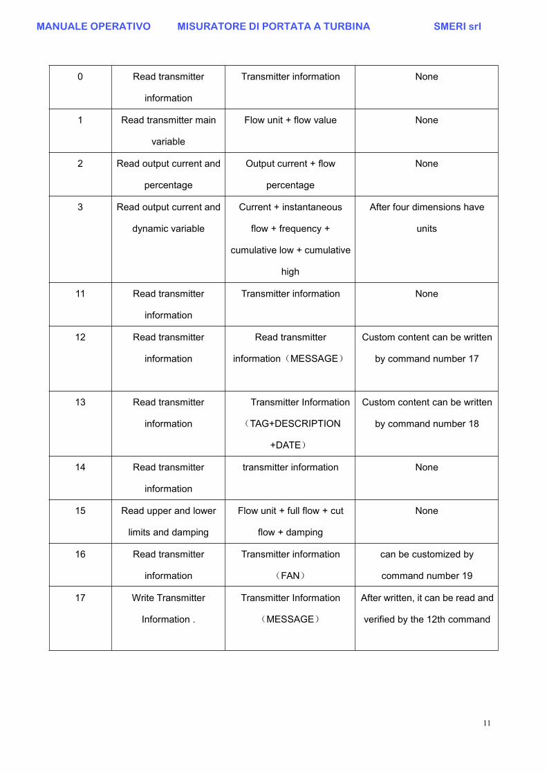
6. HART Communication
The transmitter supports two-wire 4~20mA meters to communicate with the HART general
commands listed in the table below.
Command Action object Parameter meaning Description
MANUALE OPERATIVO MISURATORE DI PORTATA A TURBINA SMERI srl
11
0 Read transmitter
information
Transmitter information None
1 Read transmitter main
variable
Flow unit + flow value None
2 Read output current and
percentage
Output current + flow
percentage
None
3 Read output current and
dynamic variable
Current + instantaneous
flow + frequency +
cumulative low + cumulative
high
After four dimensions have
units
11 Read transmitter
information
Transmitter information None
12 Read transmitter
information
Read transmitter
information(MESSAGE)
Custom content can be written
by command number 17
13 Read transmitter
information
Transmitter Information
(TAG+DESCRIPTION
+DATE)
Custom content can be written
by command number 18
14 Read transmitter
information
transmitter information None
15 Read upper and lower
limits and damping
Flow unit + full flow + cut
flow + damping
None
16 Read transmitter
information
Transmitter information
(FAN)
can be customized by
command number 19
17 Write Transmitter
Information .
Transmitter Information
(MESSAGE)
After written, it can be read and
verified by the 12th command
MANUALE OPERATIVO MISURATORE DI PORTATA A TURBINA SMERI srl

12
18 Write Transmitter
Information .
Transmitter Information
(TAG+DESCRIPTION
+DATE)
can be read and verified by
command 13 after writing.
19 Write Transmitter
Information .
Transmitter Information .
(FAN)
it can be read and verified by
command No. 16. after writing
34 Modify Damping Damping None
35 Modify upper and lower
limits and units
Unit + full flow + cut flow None
40 Output Current Output Current Value
(4~20mA Range)
Execute this command, the
transmitter will immediately
output the specified current
value.
44 Modifying Units Flow Units None
45 Calibrate the 4mA
current
The current value of the
transmitter output
measured by the precision
ammeter
First use the 40 command,
output 4mA current, then
measure the actual output
value, use this command to
calibrate
46 Calibrate the 20mA
current The current
value of the transmitter
output measured by the
ammeter
First use the 40 command,
output 20mA current,
Then measure the actual
output value and use this
command to calibrate
110 Read extended dynamic
variables
Transmitter extended
dynamic variable
(temperature + pressure)
The first variable is
temperature; the second
variable is pressure
Table 5 Transmitter HART Command
See HART SPEC V5 and above for details and definitions of HART commands.
MANUALE OPERATIVO MISURATORE DI PORTATA A TURBINA SMERI srl

13
Attachment: Troubleshooting
1) Conventional volume flow and conventional gas mass flow in algorithm selection:
The conventional volumetric flow rate in the algorithm refers to the flow rate of the working
condition indicating that the flow rate is not compensated, and is used for liquid or
uncompensated working condition gas. The standard gas volume flow rate is calculated
according to the gas equation, and the conventional gas mass flow rate is calculated by
multiplying the standard volume by the standard density.
2) Flow correction factor:
In the flow calculation, the flow rate is corrected by calculating the flow rate according to the
basic formula. The correction factor is usually set to the percentage point of the calibration point
relative to the full-scale flow rate; the correction factor C = standard flow rate / measured flow
value when not corrected. Linear interpolation between points. When not corrected, C=1, and the
corrected value is limited to the range of 0.8-1.2.
3) Pulse output type and usage:
The signal pulse in the pulse output type is the output that tracks the original signal pulse and is
typically used for initial calibration. The correction frequency is used for the frequency output after
multi-segment polyline correction. The frequency output is an instantaneous flow linear output of
0-1000 Hz, and the output frequency is 1000 Hz at full flow. The correction factor C value linear
correction and compensation calculation are valid for the frequency output, and are usually used
for the corrected output. The pulse output is calculated as the cumulative flow rate. There is a
maximum and minimum limit for the output value of each calculation cycle. The appropriate pulse
equivalent must be selected so that the number of pulses per cycle is lower than the limit of the
upper limit of 1000 pulses.
4) Pulse equivalent:
The pulse equivalent is the output factor and its value is the flow unit/pulse. That is, how many
unit flows per pulse represents, and the value must be such that the pulse output is controlled
within 1000 pulses per measurement period.
MANUALE OPERATIVO MISURATORE DI PORTATA A TURBINA SMERI srl

14
5) Temperature and pressure calibration during production and maintenance:
The temperature calibration should have a standard resistance box or a standard resistance
corresponding to the calibration value. After connecting the resistors in the corresponding menu,
press the “E” key to confirm. If the value is normal, confirm the save again. If you modify it, press
“+” to change the confirmation prompt to modified and press “E” to save the value. At Pt100, the
temperature double jumper should be shorted. At Pt1000, the temperature double jumper should
be disconnected.
6) Calibration of output current:
For the calibration of the output current, connect the standard ammeter to the current loop. After
confirming the 4/12/20mA item, press the “E” key to confirm that there should be an approximate
current output. At this time, the actual display value of the ammeter is entered and confirmed.
calibration. Usually three points per calibration should be performed.
7) Use of HART:
The use of HART should connect the Communicator to both ends of the 250 ohm sampling
resistor in the current loop. A resistance deviation of more than 20% or a zero current of less than
3.9 mA may cause HART communication to fail. Pay special attention to the current when the
current is not enough to make the zero current less than 3.9mA.
MANUALE OPERATIVO MISURATORE DI PORTATA A TURBINA SMERI srl

15
VT2WTwo-wire SystemWiring Diagram
MANUALE OPERATIVO MISURATORE DI PORTATA A TURBINA SMERI srl


