14. L. Friedrich and A. Rohrbach, “Improved interferometric tracking of trapped particles using two frequency-
detuned beams,” Opt. Lett. 35(11), 1920–1922 (2010).
15. M. J. Padgett and R. Di Leonardo, “Holographic optical tweezers and their relevance to lab on chip devices,” Lab
Chip 11(7), 1196–1205 (2011).
16. P. Schiro, C. Dubois, and A. Kwok, “Large capture-range of a single-beam gradient optical trap,” Opt. Express
11(25), 3485–3489 (2003).
#154166 - $15.00 USD Received 8 Sep 2011; revised 19 Oct 2011; accepted 20 Oct 2011; published 2 Dec 2011(C) 2011 OSA 5 December 2011 / Vol. 19, No. 25 / OPTICS EXPRESS 25833
17. A. Rohrbach, H. Kress, and E. H. Stelzer, “Three-dimensional tracking of small spheres in focused laser beams:
influence of the detection angular aperture,” Opt. Lett. 28(6), 411–413 (2003).
18. M. D. McMahon, A. J. Berglund, P. Carmichael, J. J. McClelland, and J. A. Liddle, “3D particle trajectories
observed by orthogonal tracking microscopy,” ACS Nano 3(3), 609–614 (2009).
19. E. Toprak, H. Balci, B. H. Blehm, and P. R. Selvin, “Three-dimensional particle tracking via bifocal imaging,”
Nano Lett. 7(7), 2043–2045 (2007).
20. H. P. Kao and A. S. Verkman, “Tracking of single fluorescent particles in three dimensions: use of cylindrical
optics to encode particle position,” Biophys. J. 67(3), 1291–1300 (1994).
21. S. R. P. Pavani and R. Piestun, “Three dimensional tracking of fluorescent microparticles using a photon-limited
31. F. C. Cheong, B. J. Krishnatreya, and D. G. Grier, “Strategies for three-dimensional particle tracking with
holographic video microscopy,” Opt. Express 18(13), 13563–13573 (2010).
32. O. Otto, F. Czerwinski, J. L. Gornall, G. Stober, L. B. Oddershede, R. Seidel, and U. F. Keyser, “Real-time
particle tracking at 10,000 fps using optical fiber illumination,” Opt. Express 18(22), 22722–22733 (2010).
33. H. Hajjoul, S. Kocanova, I. Lassadi, K. Bystricky, and A. Bancaud, “Lab-on-Chip for fast 3D particle tracking in
living cells,” Lab Chip 9(21), 3054–3058 (2009).
34. A. J. Berglund, M. D. McMahon, J. J. McClelland, and J. A. Liddle, “Theoretical model of errors in micromirror-
based three-dimensional particle tracking,” Opt. Lett. 35(11), 1905–1907 (2010).
35. D. B. Conkey, R. P. Trivedi, S. R. P. Pavani, I. I. Smalyukh, and R. Piestun, “Three-dimensional parallel particle
manipulation and tracking by integrating holographic optical tweezers and engineered point spread functions,”
Opt. Express 19(5), 3835–3842 (2011).
36. B. Kemper, P. Langehanenberg, A. Hoink, G. von Bally, F. Wottowah, S. Schinkinger, J. Guck, J. Kas, I.
Bredebusch, J. Schnekenburger, and K. Schütze, “Monitoring of laser micromanipulated optically trapped cells
by digital holographic microscopy,” J. Biophotonics 3(7), 425–431 (2010).
37. F. Merola, L. Miccio, M. Paturzo, A. Finizio, S. Grilli, and P. Ferraro, “Driving and analysis of micro-objects by
digital holographic microscope in microfluidics,” Opt. Lett. 36(16), 3079–3081 (2011).
38. R. C. Gonzalez and R. E. Woods, Digital Image Processing, 2nd ed. (Addison - Wesley Longman, Boston 1992).
39. A. El Mallahi and F. Dubois, “Dependency and precision of the refocusing criterion based on amplitude analysis
in digital holographic microscopy,” Opt. Express 19(7), 6684–6698 (2011).
40. L. Miccio, D. Alfieri, S. Grilli, P. Ferraro, A. Finizio, L. De Petrocellis, and S. D. Nicola, “Direct full
compensation of the aberrations in quantitative phase microscopy of thin objects by a single digital hologram,”
Appl. Phys. Lett. 90(4), 041104 (2007).
41. E. Allaria, S. Brugioni, S. Denicola, P. Ferraro, S. Grilli, and R. Meucci, “Digital holography at 10.6 µm,” Opt.
Commun. 215(4-6), 257–262 (2003).
42. T. Ellenbogen, A. Ganany-Padowicz, and A. Arie, “Nonlinear photonic structures for all-optical deflection,” Opt.
Express 16(5), 3077–3082 (2008).
43. N. Yu, M. A. Kats, C. Pflügl, M. Geiser, Q. J. Wang, M. A. Belkin, F. Capasso, M. Fischer, A. Wittmann, J.
Faist, T. Edamura, S. Furuta, M. Yamanishi, and H. Kan, “Multi-beam multi-wavelength semiconductor lasers,”
Appl. Phys. Lett. 95(16), 161108 (2009).
44. M. Paturzo, A. Pelagotti, A. Finizio, L. Miccio, M. Locatelli, A. Gertrude, P. Poggi, R. Meucci, and P. Ferraro,
“Optical reconstruction of digital holograms recorded at 10.6 microm: route for 3D imaging at long infrared
wavelengths,” Opt. Lett. 35(12), 2112–2114 (2010).
#154166 - $15.00 USD Received 8 Sep 2011; revised 19 Oct 2011; accepted 20 Oct 2011; published 2 Dec 2011(C) 2011 OSA 5 December 2011 / Vol. 19, No. 25 / OPTICS EXPRESS 25834
1. Introduction
Nowadays the incredible development of bio-microfluidic technology [1,2] highly demands
for substantial advancements in multifunctional tools for characterization, monitoring, and
manipulation in microfluidic environments. In recent years, the number of proposed and
implemented techniques for diagnostic purposes is greatly grown. Single approaches have
been demonstrated for imaging, phase-contrast quantitative analysis [3–13], manipulation and
trapping [14–16], tracking of micro-objects (i.e. nano-drops, carbon nanotubes, bio-cells,
quantum dots, dielectric spheres and for metallic spheres [17], nano- and micro-particles
[18]), tracking of both non-fluorescent [19] and fluorescent particles [20,21]. Many
techniques accomplish the tracking with high detection accuracy of a single particle [22–24]
and others in which a statistical localization algorithms have been proposed [25,26]. Tracking
objects in three-dimensional space using digital multiplexing holography have been presented
recently [27]. Also a three-dimensional tracking of Brownian motion of a particle trapped in
optical tweezers was reported [28].
Elective approaches to be adopted in microfluidic environments are optical/photonics ones
that have the remarkable advantage to be non-contact, full-field, non-invasive and can be
packaged thanks to the integrated optics and optofluidic modalities [2,29]. Various
microfluidic platforms have been developed for manipulating droplets, handling micro-nano-
objects, visualize and quantify processes occurring in-loco and for direct application for lab-
on-a chip configurations. In fact, phase-contrast approaches, adapted to a lab-on-a-chip
configurations, have given the possibility to get quantitative information with remarkable
lateral and vertical resolution directly in situ. Moreover, techniques for tracking of micro-
objects needs to be developed for measuring velocity fields, trajectories patterns, motility of
cancer cell and so on [3,30]. In ref [31]. the video stream captured by an in-line holographic
microscope can be analyzed on a frame-by-frame basis to track individual colloidal particles
experiencing three-dimensional motions with nanometer resolution. In [32] is introduced
optical fiber illumination for real-time tracking of optically trapped micrometer-sized particles
with microsecond time resolution. Digital shearing method was adopted in [30] to extract
three-component velocity in particle image velocimetry.
Several particle-tracking and imaging methods have achieved three-dimensional
sensitivity through the introduction of angled micromirrors into the observation volume of an
optical microscope [18,33]. In ref [34]. the authors developed a theoretical model of the
imaging response of such devices and show how the direct and reflected images of a
fluorescent particle are affected. In particle-tracking applications, asymmetric image
degradation manifests itself as systematic tracking errors. Recently some experiments have
been performed to get simultaneous trapping and tracking, but, in order to achieve this double
function, they used two coupled lasers systems [31,35,36]. In this paper, we show a
completely new concept of a compact holographic microscope that can ensure the multi-
functionality, accomplishing, by the same configuration and simultaneously, accurate 3D
tracking and quantitative phase-contrast analysis. Experimental results are presented and
discussed for in vitro cells in microfluidic environment. The system is very simple and
compact and is based on twins-laser-beams coming from a single laser source. Through this
simple conceptual design we show how two different functionalities can be accomplished by
the same optical setup, i.e. 3D tracking of micro-object and quantitative phase contrast
imaging. It is important to note that by same system it is possible accomplish other two
different functionalities, i.e. for driving particles along appropriate paths, performing
simultaneously their interferometric analysis [37].
#154166 - $15.00 USD Received 8 Sep 2011; revised 19 Oct 2011; accepted 20 Oct 2011; published 2 Dec 2011(C) 2011 OSA 5 December 2011 / Vol. 19, No. 25 / OPTICS EXPRESS 25835
2. Working principle
2.1 Optical configuration
The optical configuration is illustrated in Fig. 1. The particles/cells are loaded in a chamber of
about 5x5x0.3mm, assembled by using two cover glasses (0.15 mm thick) with a double-sided
tape spacer (0.3 mm thick). Two beams, coming from the same DPSS laser (532nm, 250mW),
enter into the microscope objective (oil immersion Nikon 100x, 1.2 NA). The two beams are
sent slightly off-axis through the same microscope objective. The angle between the beams is
about 4 degrees. Since the two beams passes through the same microscope objective, in
principle they are in focus in the same image plane. Nevertheless the twin beams can
experience aberrations giving rise to some focus-shift too. A 20x microscope objective is used
to obtain an image on a CCD plane. The tracking is performed by evaluating the double out-
of-focus projections of the particles due to the twin-beams onto the array detector plane. The
principle is simple and allows tracking in 3D. In fact as shown in Fig. 1 each particle forms
two shadows on the CCD array, The separation between the two shadows is a function of the
longitudinal position of the particle. By the very same configuration also digital holograms
can be directly recorded with the aim to obtain quantitative phase contrast images of the
micro-objects as depicted in Fig. 1.
Fig. 1. Twin-beams digital holography microscope.
2.2 Modeling for 3D tracking
In our model, we have two plane beams sent through an objective microscope. The
experimental configuration is depicted in Fig. 2. The lens makes a Fourier transformation thus
focusing the two beams, in ideal condition without considering the aberrations, in its back
focal plane. An additional lens is used to image the microfluidic volume. Essentially we can
sketch the imaged volume as composed by two cones, transmitted into the microfluidic
sample. The two cones (see Fig. 2) are partially superimposed in the image space. On the
CCD digital sensor, the intersection between the beam and the sensor plane of each cone is a
circle ellipse with radius c
r d<< , where dc is the distance between the digital sensor and the
vertex of cone. Supposing that the principal axes of cones are parallel, we consider a reference
system of coordinates Oxyz where the plane xy is on the digital sensor with O in the center. In
this reference system, we define the vertex of both cones ( )1 1 1 1, ,C x y z and ( )2 2 2 2
, ,C x y z
where ( )1 1,x y and ( )2 2
,x y are given by the center of two circles in the sensor plane and
#154166 - $15.00 USD Received 8 Sep 2011; revised 19 Oct 2011; accepted 20 Oct 2011; published 2 Dec 2011(C) 2011 OSA 5 December 2011 / Vol. 19, No. 25 / OPTICS EXPRESS 25836
1 2 cz z d= = − . Then we suppose that a microscopic object, that can be considered a point with
coordinates ( ), ,p p pP x y z , is in the volume defined by the union of the two cones, that is
( ) ( )1 1 2 2, ,P C C∈ Ω ∪ Ω , where
1 2,Ω Ω are the cones solid angles. In this scenario, we have
three possible situations. ( )1 1,P C∈ Ω , in this case we will have a projection of the point P on
the sensor plane in the circle relative to the cone 1. If ( )2 2,P C∈ Ω we have a projection of
the point P on the sensor plane in the circle relative to the cone 2. Finally if
( ) ( )1 1 2 2, ,P C C∈ Ω ∩ Ω , in this case we have two projections of the point P on the sensor
plane (see Fig. 1), i.e. each twin laser beam makes a projection (or shadow) of the particle on
the CCD array detector. This latter situation is interesting because we demonstrate that it is
possible to find the path of a point ( ) ( )1 1 2 2, ,P C C∈ Ω ∩ Ω using the information on the
projections coordinates, by the knowledge of the position of the two vertices C1, C2.
Supposing that the projections of P in the two circles are the points ( )1 1 1, ,0p pP x y and
( )2 2 2, ,0p pP x y respectively, the estimation of P is given by
1 1 2 2
P C P C P= ∩ (1)
where AB denote the segment joining the points ( ), ,A A A
A x y z and ( ), ,B B B
B x y z :
'
'
'
A x
A y
A z
x x l t
y y l t
z z l t
= +
= + = +
(2)
where ( )', ', 'x y z AB∈ , [ ]0,1t∈ and ( ) ( ) ( )B A
l • = • − • .
The hypothesis ( ) ( )1 1 2 2, ,P C C∈ Ω ∩ Ω assure that one and only one intersection's point
P exists.
#154166 - $15.00 USD Received 8 Sep 2011; revised 19 Oct 2011; accepted 20 Oct 2011; published 2 Dec 2011(C) 2011 OSA 5 December 2011 / Vol. 19, No. 25 / OPTICS EXPRESS 25837
Fig. 2. Simulated interference between two laser beams
2.2 Modeling for 3D tracking
To demonstrate how the tracking functionality works we firstly present here some numerical
simulations to validate the reliability of the working principle of the proposed method. In our
numerical simulations, we set ( )1112,76,
cC d− − , ( )2
112, 76,c
C d− − with 44478c
d = ,
700r = and the unit are in pixels. Using these parameters it is possible to find the aperture
angles of cones:
1 2
arctan 0.0157radc
r
dα α
= = =
(3)
from which we can find the solid angles
( )( ) 4
1 2 12 1 cos 2 1.95 10 srπ α −Ω = Ω = − ≈ ⋅ (4)
We report here simulations of two different paths of particle P. A linear path and helix
paths, respectively. The following equations give the math formulation of the two simulated
trajectories. The linear path with 0p
x ≡ , 0p
y ≡ , [ ]30000,30000p
z ∈ − .
Elliptical helix given by the following equation:
( )( ) [ ]
100sin 1000
10cos 1000 8000 ,0
p
p
p
x t
y t t
z t
π
=
= ∈ − =
(5)
For both simulated paths, we compute the mean error and the standard deviation error on
the difference between the real path and the path estimated with the proposed method.
Media 1 shows the results of these two simulation (frames on the left). From the simulated
images we evaluate the corresponding points P1 and P2 in the sensor plane for both paths. By
the knowledge of the P1 and P2 coordinates of and through Eq. (1) we reconstructed the paths.
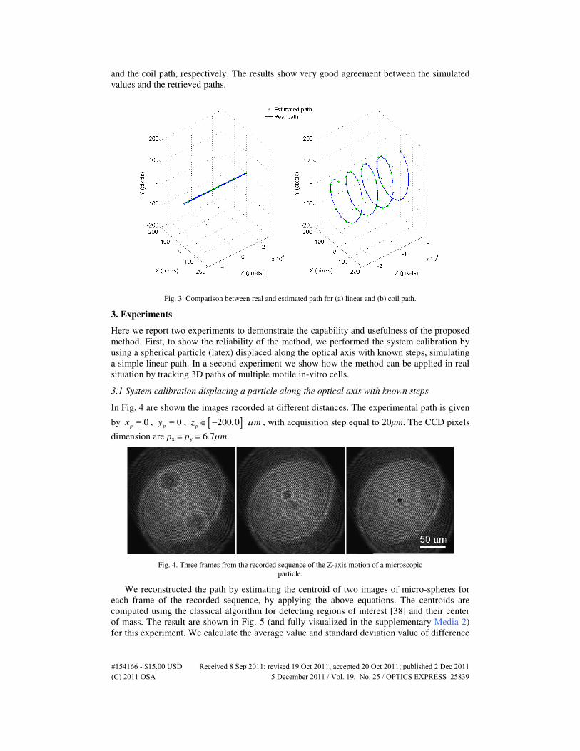
Figure 3 shows the comparison between the simulated and reconstructed paths for the linear
#154166 - $15.00 USD Received 8 Sep 2011; revised 19 Oct 2011; accepted 20 Oct 2011; published 2 Dec 2011(C) 2011 OSA 5 December 2011 / Vol. 19, No. 25 / OPTICS EXPRESS 25838
and the coil path, respectively. The results show very good agreement between the simulated
values and the retrieved paths.
Fig. 3. Comparison between real and estimated path for (a) linear and (b) coil path.
3. Experiments
Here we report two experiments to demonstrate the capability and usefulness of the proposed
method. First, to show the reliability of the method, we performed the system calibration by
using a spherical particle (latex) displaced along the optical axis with known steps, simulating
a simple linear path. In a second experiment we show how the method can be applied in real
situation by tracking 3D paths of multiple motile in-vitro cells.
3.1 System calibration displacing a particle along the optical axis with known steps
In Fig. 4 are shown the images recorded at different distances. The experimental path is given
by 0p
x ≡ , 0p
y ≡ , [ ]200,0p
z mµ∈ − , with acquisition step equal to 20µm. The CCD pixels
dimension are px = py = 6.7µm.
Fig. 4. Three frames from the recorded sequence of the Z-axis motion of a microscopic
particle.
We reconstructed the path by estimating the centroid of two images of micro-spheres for
each frame of the recorded sequence, by applying the above equations. The centroids are
computed using the classical algorithm for detecting regions of interest [38] and their center
of mass. The result are shown in Fig. 5 (and fully visualized in the supplementary Media 2)
for this experiment. We calculate the average value and standard deviation value of difference
#154166 - $15.00 USD Received 8 Sep 2011; revised 19 Oct 2011; accepted 20 Oct 2011; published 2 Dec 2011(C) 2011 OSA 5 December 2011 / Vol. 19, No. 25 / OPTICS EXPRESS 25839
between the estimated positions and real position having 1.07µm and 2.02µm, respectively.
Since the ratio between the standard deviation computed and the acquisition step is
approximately 10%, we have the similar accuracy show in the z-localization proposed in [22].
Fig. 5. Comparison between real and estimated path for real sequence.
3.2 Tracking 3D paths of multiple cells
The method was finally applied to a real experimental situation in which we had various
particles (cells) floating into a microfluidic environment chamber. In the considered case we
did not have a priori information on those floating in-vitro cells, while they are subject to a
displacement field in the microfluidic sample. We simply recorded, with the experimental
configuration in Fig. 1 a sequence of images. The digital sensor was a CCD array as in the
same setup of previous experiment. In Fig. 6 are shown three frames corresponding to the
passage of three different cells across the imaged volume. Also in this case, we estimated the
centroids of cell by an image processing algorithm for each frame of the recorded movie.
Fig. 6. Recording sequence of random motion of cells.
The results of the retrieved 3D paths of the cells were easily estimated by the proposed
method. The results, i.e. the 3D plot of the paths, are shown in Fig. 7. The dynamic evolutions
can be seen in full in the supplementary Media 3.
#154166 - $15.00 USD Received 8 Sep 2011; revised 19 Oct 2011; accepted 20 Oct 2011; published 2 Dec 2011(C) 2011 OSA 5 December 2011 / Vol. 19, No. 25 / OPTICS EXPRESS 25840
Fig. 7. Estimated path for random motion of the three cells shows in Fig. 6.
From the last result, it is clear that all the three cells follow paths along the same
streamlines in the microfluidic flux. However, can be noted that cells experience a
displacement mainly along the longitudinal axis. This is due to the twins beams that have
surely a role in influencing and/or determining the paths followed by the particles, because of
both scattering (radiation pressure) and the attractive force (similar to optical tweezers).
Nevertheless the optical configuration can be designed to cancel the effect of the light on the
paths. In fact by using a trivial stroboscopic illumination, depending also on the velocity
fields of the particles, the influence of the light on the paths can be drastically reduced up to
become completely negligible, making this method a full non-invasive 3D tracking approach.
4. Quantitative phase – contrast microscopy of tracked particles
In addition to the tracking functionality we show here that the same set-up can be adopted as
quantitative phase contrast microscope. In fact due to the coherence properties of the adopted
laser source we can see that the twin-beams interfere to produce nice interference fringe
patterns at the CCD sensor plane. Indeed the interference patterns, as those in Figs. 4 and 6,
are really digital holograms. Such digital holograms contain quantitative information about
the cells. In fact optical path length variations due to the presence of the cells along can be
retrieved easily. Digital holograms (i.e., each frames of the recorded movies) can be
numerically reconstructed by well known diffraction propagation methods to get the
quantitative phase contrast maps of the cells (QPMs). We adopted the holographic
reconstruction by the convolution method [8,37–41]. In Fig. 8, we show an example of the
phase-contrast map of the cell A.
#154166 - $15.00 USD Received 8 Sep 2011; revised 19 Oct 2011; accepted 20 Oct 2011; published 2 Dec 2011(C) 2011 OSA 5 December 2011 / Vol. 19, No. 25 / OPTICS EXPRESS 25841
Fig. 8. (a) phase reconstruction of a single acquisition with estimated in-focus distance;
(b) unwrapping of in-focus phase image.
It is important to note that digital holography method could also give the 3D tracking of
the particles in the imaged volume. In fact the numerical reconstruction of the whole complex
optical wavefront would allow to have reconstructions at different depths (i.e. at various
distances from the CCD array, on the hologram plane). However it is well known that have
accurate information of the axial position of a particles it would be necessary to assess with
high accuracy of the in-focus position [39]. Various method have been investigated and
demonstrated for this aim and the topic is still matter of intensive investigation. Different
strategies have been proposed and often quite heavy computational efforts are necessary to get
the good in-focus images and sometimes high uncertainties still remain. The method proposed
here, on the contrary, allows quite easy calculation of the depth coordinate of the particles.
5. Conclusion
We developed a simple and compact digital holographic microscope in off-axis configuration
by using two twins laser beams passing through the same microscope objective. We
demonstrate the effectiveness of this novel configuration that can be especially suitable for
phase contrast analysis and 3D imaging of biological sample and microfluidic devices. We
implemented experimental the set-up, validated the model either numerically and from the
experimental point of view. Demonstration of the 3D tracking and the capability to perform
Quantitative Phase-Contrast microscopic analysis, on multiple moving in-vitro cells in a
microfluidic environment, was finally performed and we believe can be useful in lab-on-a-
chip devices. The optical configuration is very simple as it is made by only two beams. The
beams can be produced by various configurations such a diffraction grating at the input pupil
of the microscope objective, or even by using a spatial light modulator [13]. Furthermore, to
make the optical configuration very compact, specialized laser devices can be used for
generating the twin-beams simultaneously. For example, in the visible spectral region, the
second harmonic generation in PPLN crystals can be used for the simultaneous generation of
twins beams at 532 nm [42], while in mid-IR (10 µm) multibeams generation can be achieved
by quantum cascade lasers [43] in a region of the spectrum in which digital holography has
been demonstrated too [41,44].
#154166 - $15.00 USD Received 8 Sep 2011; revised 19 Oct 2011; accepted 20 Oct 2011; published 2 Dec 2011(C) 2011 OSA 5 December 2011 / Vol. 19, No. 25 / OPTICS EXPRESS 25842