37
May 28-30, 2003 Two-Phase Heat Transfer Lab
| Date post: | 28-Dec-2015 |
| Category: |
Documents |
| Upload: | francis-perry |
| View: | 218 times |
| Download: | 1 times |

May 28-30, 2003 Two-Phase Heat Transfer Lab
Analytical And Experimental Investigation of Analytical And Experimental Investigation of Evaporation from Porous Capillary StructuresEvaporation from Porous Capillary Structures
Presented toONR Materials Research Review Meeting
May 28-30, 2003Woods Hole, MA
G.P. “Bud” Peterson, C. Li and G. BenitizDepartment of Mechanical, Aerospace & Nuclear Engineering,
Rensselaer Polytechnic InstituteTroy, NY 12180

May 28-30, 2003 Two-Phase Heat Transfer Lab
What is a What is a Heat PipeHeat Pipe??

May 28-30, 2003 Two-Phase Heat Transfer Lab
How does it work?How does it work?

May 28-30, 2003 Two-Phase Heat Transfer Lab
What is it good for?What is it good for?
May 28-30, 2003 Two-Phase Heat Transfer Lab
Analytical Modeling Analytical Modeling • Formation of the thin liquid filmFormation of the thin liquid film• Evaporation limitEvaporation limit
Experimental InvestigationExperimental Investigation Results and DiscussionResults and Discussion Applications and SignificanceApplications and Significance AAckcknowledgementnowledgement
OOUTLINEUTLINE

May 28-30, 2003 Two-Phase Heat Transfer Lab
Objective:Objective:– To investigate the formation of thin films on capillary surfaces;To investigate the formation of thin films on capillary surfaces;
– To determine the evaporation limit on capillary surface; To determine the evaporation limit on capillary surface;
– To enhance the evaporation limit through optimization of the To enhance the evaporation limit through optimization of the
pore structure, physical properties such as thermal conductivity pore structure, physical properties such as thermal conductivity
and wettability;and wettability;
– To maximize the capillary pumping capability through the To maximize the capillary pumping capability through the
optimization of the evaporation heat transfer limit. optimization of the evaporation heat transfer limit.
BBACKGROUNDACKGROUND
May 28-30, 2003 Two-Phase Heat Transfer Lab
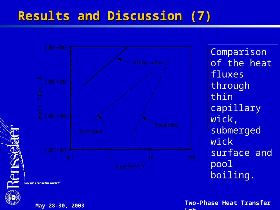
Results Results and Discussion (7)and Discussion (7)
Thin film surface
1.0E+03
1.0E+04
1.0E+05
1.0E+06
0.1 1 10 100
Superheat, oC
Hea
t flu
x, W
/m2
Pool BoilingSubmerged surface
Comparison of the heat fluxes through thin capillary wick, submerged wick surface and pool boiling.

May 28-30, 2003 Two-Phase Heat Transfer Lab
Interfacial RegionInterfacial Region
Intrinsicmeniscus
Transitionregion
Liquid
Vapor
Liquid
Vapor
Thin filmregion

May 28-30, 2003 Two-Phase Heat Transfer Lab
Heat Flux DistributionHeat Flux Distribution
Heat Flux & Film ThicknessHeat Flux & Film Thickness
1000
1200
1400
1600
0 0.1 0.2 0.3 0.4 0.5 0.6 0.7 0.8 0.9 1 1.1
0
200
400
600
800
0.9
0.0
0.1
0.2
0.3
0.4
0.5
0.6
0.7
0.8
Film
Th
ickn
ess
,
(m
)
Distance, s (m)
He
at
Flu
x (W
/cm
2)
May 28-30, 2003 Two-Phase Heat Transfer Lab
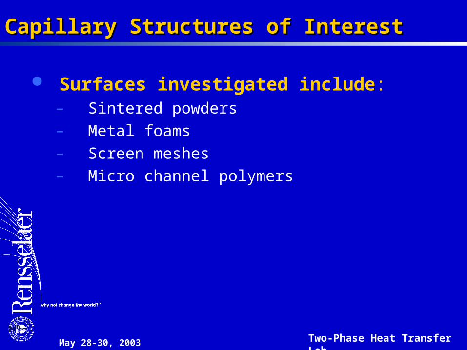
Capillary Structures of InterestCapillary Structures of Interest
Surfaces investigated include:– Sintered powders– Metal foams – Screen meshes– Micro channel polymers

May 28-30, 2003 Two-Phase Heat Transfer Lab
Mathematical Model (1)Mathematical Model (1)
Solid wall
d w 2w+
d w
w
w
Screen mesh cellScreen mesh cell Cross-section of the Cross-section of the screen meshscreen mesh
Physical Model: Evaporation process on a heated surface coated Physical Model: Evaporation process on a heated surface coated with a single layer of porous material, here metal screen mesh, with a single layer of porous material, here metal screen mesh, with liquid supplied by capillary action, producing a wetted surface with liquid supplied by capillary action, producing a wetted surface with saturated liquid in the cells. with saturated liquid in the cells.

May 28-30, 2003 Two-Phase Heat Transfer Lab
Mathematical Model Mathematical Model
oy
x
Solid wall
rm
Equilibriumregion
Thin filmregion
T v
o
R w w+
Meniscusregion
o
y
x
Solid wall
rmMeniscus
region
Thin filmregion
T lv
T v
o
R w w+
e
3
1
,
,,
,0 )(
ln)(1
c
v
iw
iwsat
vgliwsat
v
iwv P
T
T
TP
PTRTP
T
TP
A

May 28-30, 2003 Two-Phase Heat Transfer Lab
Mathematical Model Mathematical Model
The Formation of Bubbles in capillary structures is dominated by the porous structure and superheat between the heated wall and the bulk liquid-phase.
where
For ideal gas
llglsatlllsat PTRTPPvTPr
/)(exp)(
2b
)( dcvl PPPP
21 ccc KKp
3A
pd
)ln( blvgld aTRp
Critical bubble radius

May 28-30, 2003 Two-Phase Heat Transfer Lab
Mathematical Model Mathematical Model
Formation of the bubble Formation of the bubble in the sharp corner area:in the sharp corner area:
a). Superheata). Superheat
b). The geometric shape b). The geometric shape and size of the celland size of the cell
c). Capillary pressure c). Capillary pressure
d w w+
Solid wallTw
T l
Tvrm
BubbleLiquid
Vapor
Pv
WireWire
May 28-30, 2003 Two-Phase Heat Transfer Lab
Mathematical Model Mathematical Model
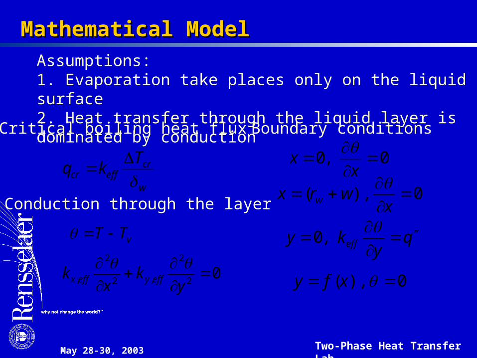
Critical boiling heat flux
Conduction through the layer
Boundary conditions
w
creffcr
Tkq
02
2
,2
2
,
yk
xk effyeffx
0,0
x
x
0),(
x
wrx w
qy
ky eff
,0
0),( xfy
vTT
Assumptions:1. Evaporation take places only on the liquid surface2. Heat transfer through the liquid layer is dominated by conduction
May 28-30, 2003 Two-Phase Heat Transfer Lab
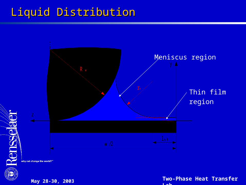
Liquid DistributionLiquid Distribution
w /2
z
y
l w 0
r m
R w
Thin film region
Meniscus region

May 28-30, 2003 Two-Phase Heat Transfer Lab
Results Results and Discussion (1)and Discussion (1)
0.5
1
1.5
2
2.5
0 0.01 0.02 0.03 0.04 0.05 0.06 0.07 0.080
0.01
0.02
0.03
0.04
0.05
0.06
0.07
0.08
X (mm)
Y (
mm
)A
Temperature distribution in the thin liquid film formed between the wires at high heat fluxes.
May 28-30, 2003 Two-Phase Heat Transfer Lab
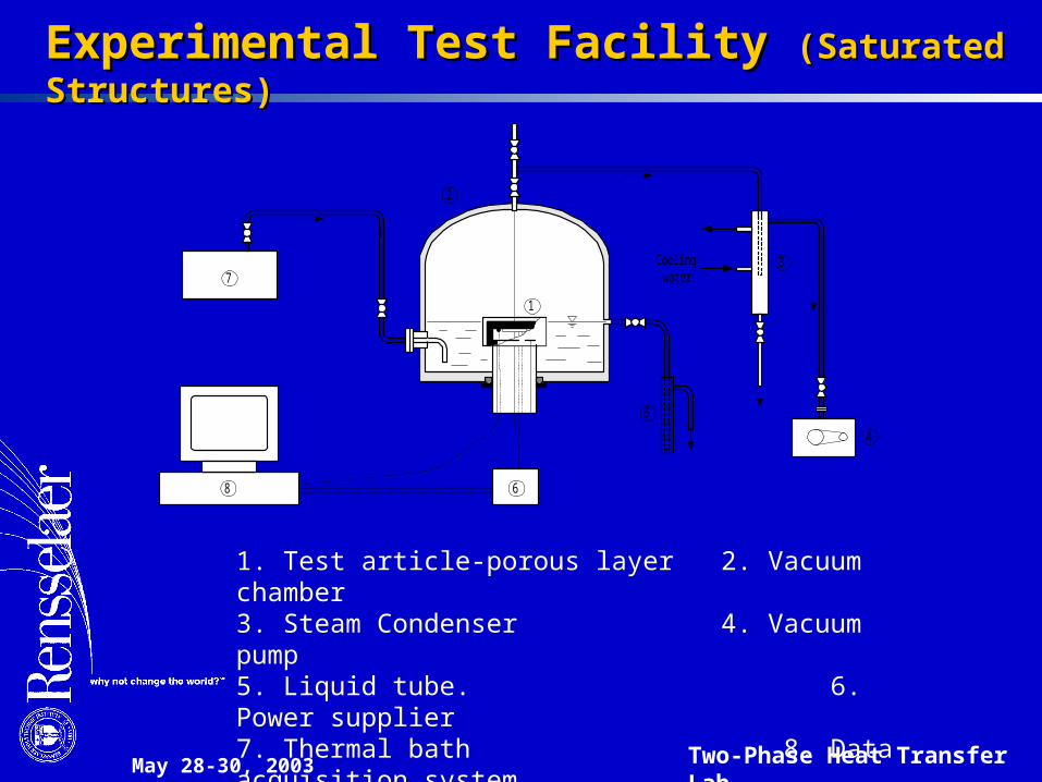
Experimental Test Facility Experimental Test Facility (Saturated Structures)(Saturated Structures)
1. Test article-porous layer 2. Vacuum chamber 3. Steam Condenser 4. Vacuum pump5. Liquid tube. 6. Power supplier7. Thermal bath 8. Data acquisition system
Coolingwater
1
6
2
3
4
5
7
8
May 28-30, 2003 Two-Phase Heat Transfer Lab
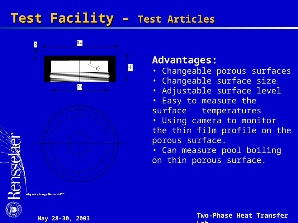
Test Facility – Test Facility – Test ArticlesTest Articles
Advantages:• Changeable porous surfaces• Changeable surface size• Adjustable surface level• Easy to measure the surface temperatures• Using camera to monitor the thin film profile on the porous surface.• Can measure pool boiling on thin porous surface.
Do
H
8
D i

May 28-30, 2003 Two-Phase Heat Transfer Lab
Triangular Grooved Polymer FilmTriangular Grooved Polymer Film
V

May 28-30, 2003 Two-Phase Heat Transfer Lab
EExperimental Test Facility xperimental Test Facility (Wicking Height Tests)(Wicking Height Tests)
PowerMeasurement
Test article
Liquid pool
Vacuum Jar
Heating bathHeat exchanger
Overflowcontainer
TemperatureMeasurement
Valve
Heater
VacuumSystem
LiquidFlask
Overflow

May 28-30, 2003 Two-Phase Heat Transfer Lab
7.0 7.0 7.0 5.030.0 30.0 30.0 15.0 15.0
177.8
Heater Micro film25.4
Thermocouple hole (0.5) Aluminum plateA
A
25.4
13.0 14.8
La
Le
Test article
Liquid
1"
Crosssection of the film
2a
w
h g
h v
h b
2w t
2a
w
2w
h g
h v
h b
t
Wetting point
EExperimental Investigation - xperimental Investigation - Test ArticlesTest Articles

May 28-30, 2003 Two-Phase Heat Transfer Lab
Results Results and Discussion and Discussion
Water-Copper mesh# 150
1.0E+04
1.0E+05
1.0E+06
1.0E+07
0 20 40 60 80 100 120 140 160 180
Tv, oC
Crit
ical
hea
t flu
x, W
/m2
Effect of operating temperature (vapor-phase pressure) on the boiling limit of copper screen mesh layer.

May 28-30, 2003 Two-Phase Heat Transfer Lab
Results Results and Discussion and Discussion
Mesh #150
0.0E+00
2.0E+05
4.0E+05
6.0E+05
8.0E+05
1.0E+06
1.2E+06
1.4E+06
1.6E+06
0 1000 2000 3000 4000
Capillary pressure, Pa
Crit
ical
hea
t flu
x, W
/m2
Effect of the capillary pressure on the boiling limit of the thin liquid film.

May 28-30, 2003 Two-Phase Heat Transfer Lab
Results Results and Discussion and Discussion
Water-Mesh #150
Cu
Al
SS
0.0E+00
2.0E+05
4.0E+05
6.0E+05
8.0E+05
1.0E+06
1.2E+06
0 50 100 150 200 250 300 350ks, W/m K
Crit
ical
hea
t flu
x, W
/m2
Effect of thermal conductivity of wick layer on the critical boiling heat flux on copper screen mesh.

May 28-30, 2003 Two-Phase Heat Transfer Lab
Thin film evaporation has a dramatically higher heat transfer Thin film evaporation has a dramatically higher heat transfer coefficient than pool boiling or submerged surfaces covered with coefficient than pool boiling or submerged surfaces covered with a thin porous layer. a thin porous layer.
Thin film evaporation can be modeled using a single cell Thin film evaporation can be modeled using a single cell approach;approach;
The formation and profile of the thin film is affected by the The formation and profile of the thin film is affected by the wettability and surface tension of the working fluid as well as heat wettability and surface tension of the working fluid as well as heat flux;flux;
The majority of the heat transfer occurs in the thin film region of The majority of the heat transfer occurs in the thin film region of the liquid meniscus resulting in a very high heat flux in this area;the liquid meniscus resulting in a very high heat flux in this area;
The evaporation heat transfer is significantly affected by the The evaporation heat transfer is significantly affected by the capillary pressure, and increases in the capillary pressure results capillary pressure, and increases in the capillary pressure results in a reduction of the evaporation heat transport limit;in a reduction of the evaporation heat transport limit;
Higher thermal conductivity wicking structures have a higher Higher thermal conductivity wicking structures have a higher evaporation heat transfer coefficient; evaporation heat transfer coefficient;
ConclusionsConclusions
May 28-30, 2003 Two-Phase Heat Transfer Lab
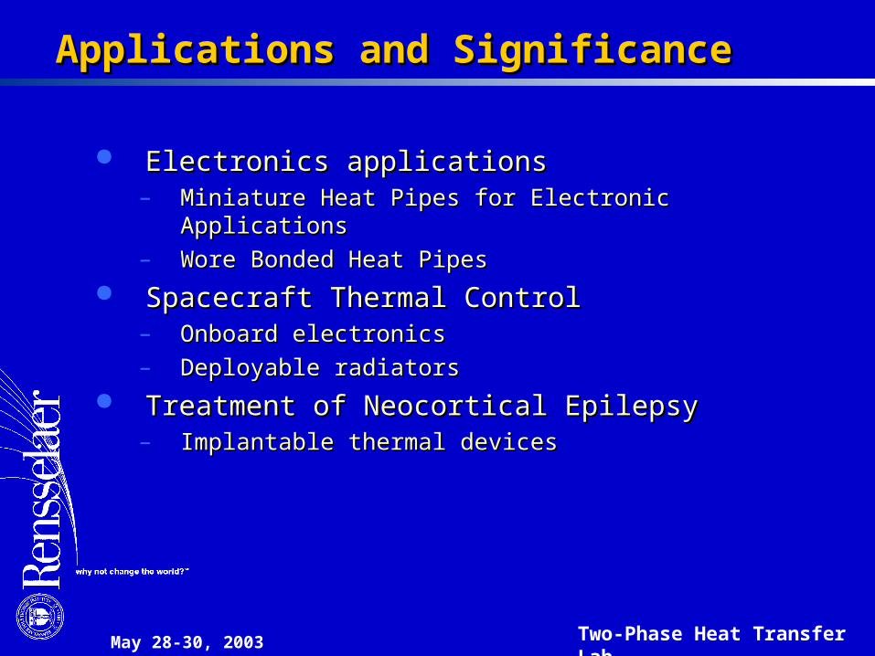
Electronics applicationsElectronics applications– Miniature Heat Pipes for Electronic ApplicationsMiniature Heat Pipes for Electronic Applications– Wore Bonded Heat PipesWore Bonded Heat Pipes
Spacecraft Thermal ControlSpacecraft Thermal Control– Onboard electronicsOnboard electronics– Deployable radiatorsDeployable radiators
Treatment of Neocortical EpilepsyTreatment of Neocortical Epilepsy– Implantable thermal devicesImplantable thermal devices
AApplications and Significancepplications and Significance
May 28-30, 2003 Two-Phase Heat Transfer Lab
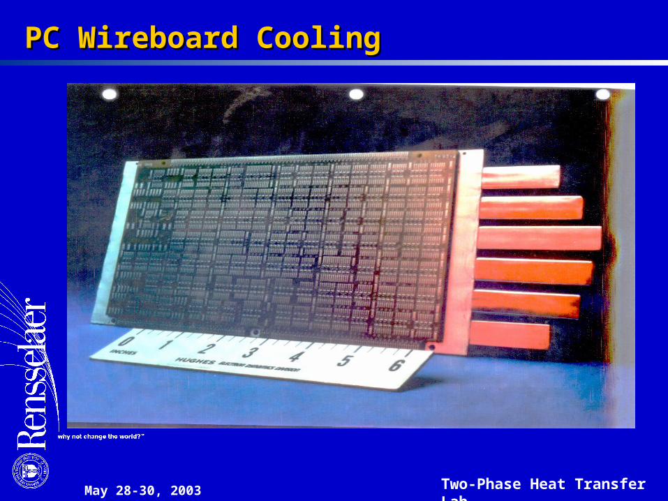
PC Wireboard CoolingPC Wireboard Cooling

May 28-30, 2003 Two-Phase Heat Transfer Lab
Miniature Heat Pipes for Electronics ApplicationsMiniature Heat Pipes for Electronics Applications
May 28-30, 2003 Two-Phase Heat Transfer Lab
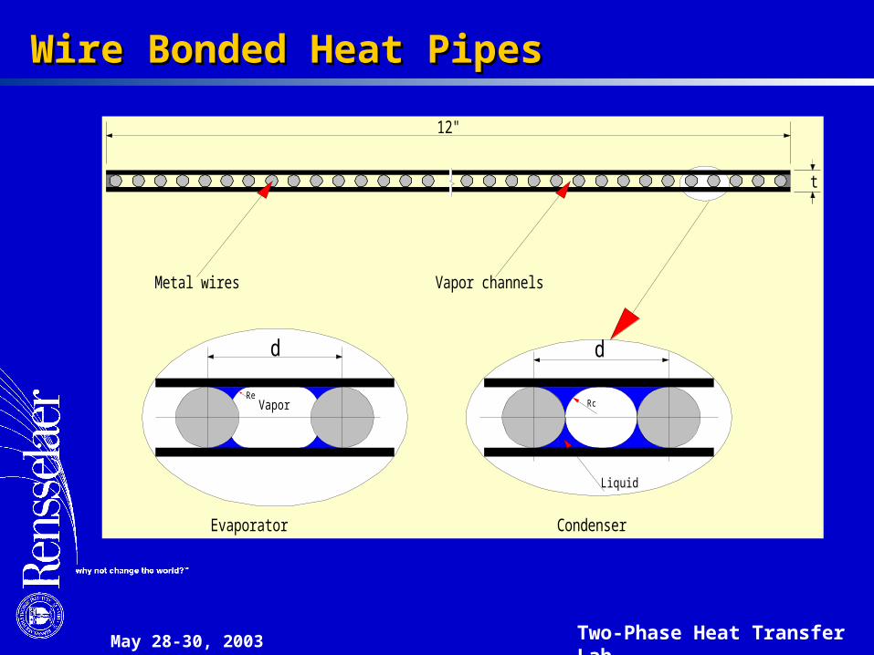
Wire Bonded Heat PipesWire Bonded Heat Pipes
Evaporator Condenser
Metal wires Vapor channels
t
Vapor
Liquid
RcRe
d d
12"

May 28-30, 2003 Two-Phase Heat Transfer Lab
Transhab Spacecraft (Stowed)Transhab Spacecraft (Stowed)

May 28-30, 2003 Two-Phase Heat Transfer Lab
Transhab Spacecraft (Deployed)Transhab Spacecraft (Deployed)
May 28-30, 2003 Two-Phase Heat Transfer Lab
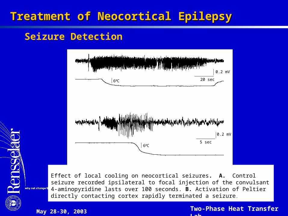
Treatment of Neocortical EpilepsyTreatment of Neocortical Epilepsy
Effect of local cooling on neocortical seizures. A. Control seizure recorded ipsilateral to focal injection of the convulsant 4-aminopyridine lasts over 100 seconds. B. Activation of Peltier directly contacting cortex rapidly terminated a seizure.
0.2 mV
20 sec
0.2 mV
5 sec60C
60C
Seizure Detection
May 28-30, 2003 Two-Phase Heat Transfer Lab
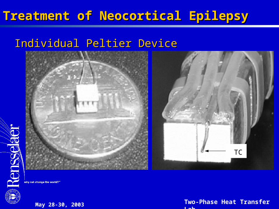
Treatment of Neocortical EpilepsyTreatment of Neocortical Epilepsy
Individual Peltier DeviceIndividual Peltier Device
TC
May 28-30, 2003 Two-Phase Heat Transfer Lab
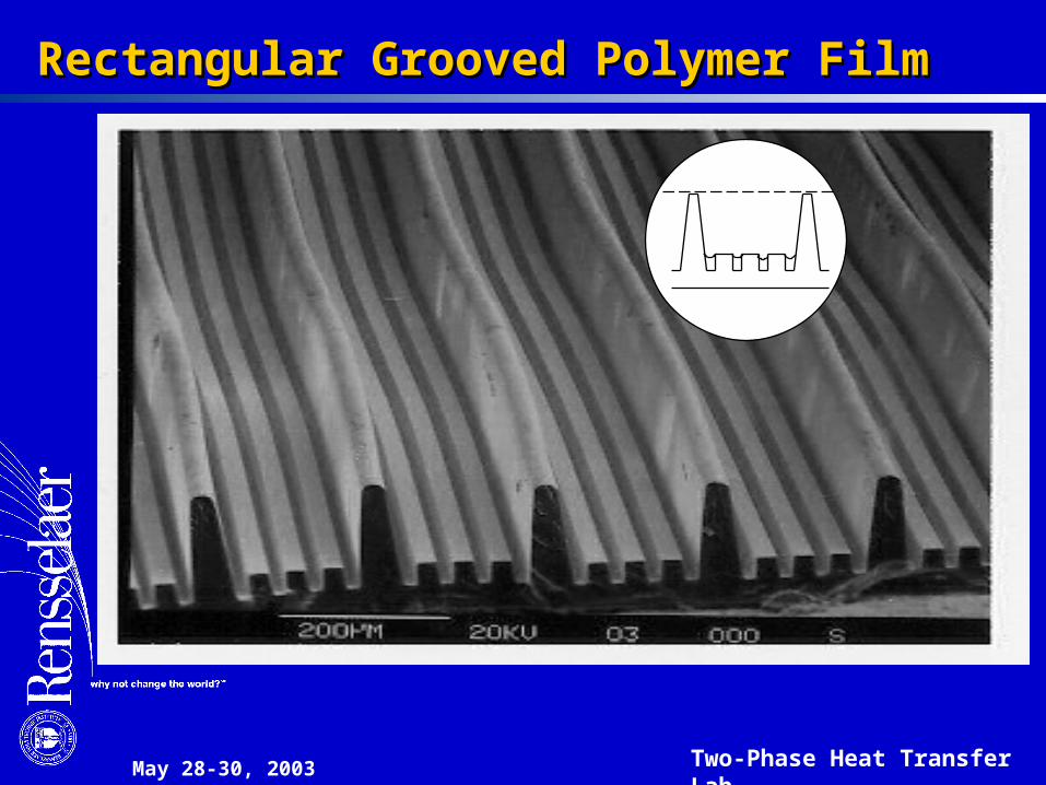
Rectangular Grooved Polymer FilmRectangular Grooved Polymer Film

May 28-30, 2003 Two-Phase Heat Transfer Lab
The authors would like to acknowledge the support of the Office of Naval Research.
AcknowledgementAcknowledgement


