58
August 2014 8065D www.sencore.com | 1.605.978.4600 Revision 1.3 TXS 3600 Multichannel Video/Audio Transcoder User Manual

August 2014 8065D www.sencore.com | 1.605.978.4600 Revision 1.3
TXS 3600 Multichannel Video/Audio Transcoder
User Manual

TXS 3600 - User Manual
Page 2 (58)
Copyright © 2014 Sencore, Inc. All rights reserved. 3200 Sencore Drive, Sioux Falls, SD USA www.sencore.com This publication contains confidential, proprietary, and trade secret information. No part of this document may be copied, photocopied, reproduced, translated, or reduced to any machine-readable or electronic format without prior written permission from Sencore. Information in this document is subject to change without notice and Sencore Inc. assumes no responsibility or liability for any errors or inaccuracies. Sencore, Sencore Inc, and the Sencore logo are trademarks or registered trademarks in the United States and other countries. All other products or services mentioned in this document are identified by the trademarks, service marks, or product names as designated by the companies who market those products. Inquiries should be made directly to those companies. This document may also have links to third-party web pages that are beyond the control of Sencore. The presence of such links does not imply that Sencore endorses or recommends the content on those pages. Sencore acknowledges the use of third-party open source software and licenses in some Sencore products. This freely available source code can be obtained by contacting Sencore Inc.
About Sencore Sencore is an engineering leader in the development of high-quality signal transmission solutions for the broadcast, cable, satellite, IPTV, telecommunications, and professional audio/video markets. The company’s world-class portfolio includes video delivery products, system monitoring and analysis solutions, and test and measurement equipment, all designed to support system interoperability and backed by best-in-class customer support. Sencore meets the rapidly changing needs of modern media by ensuring the efficient delivery of high-quality video from the source to the home. For more information, visit www.sencore.com.

TXS 3600 - User Manual
Page 3 (58)
Revision History
Date Version Description Author
7/20/2012 1.0 2.0.0 Release JKS
12/26/2012 1.1 Updated with 2.1.0 Features JKS
11/12/2013 1.2 Updated with 2.3.0 Features NDM
8/15/2014 1.3 Updated with 2.4.0 Features NDM

TXS 3600 - User Manual
Page 4 (58)
Safety Instructions
Read these instructions
Keep these instructions
Heed all warnings
Follow all instructions
Do not use this apparatus near water
Clean only with dry cloth
Do not block any ventilation openings. Install in accordance with the manufacturer’s instructions
Do not install near any heat sources such as radiators, heat registers, stoves, or other apparatus (including amplifiers) that produce heat
Do not defeat the safety purpose of the polarized or grounding-type plug. A polarized plug has two blades with one wider than the other. A grounding type plug has two blades and a third grounding prong. The wide blade or the third prong is provided for your safety. If the provided plug does not fit into your outlet, consult an electrician for replacement of the obsolete outlet.
Protect the power cord from being walked on or pinched particularly at plugs, convenience receptacles, and the point where they exit from the apparatus.
Only use attachments/accessories specified by the manufacturer.
Unplug this apparatus during lightning storms or when unused for long periods of time.
Refer all servicing to qualified service personnel. Servicing is required when the apparatus has been damaged in any way, such as power-supply cord or plug is damaged, liquid has been spilled or objects have fallen into the apparatus, the apparatus has been exposed to rain or moisture, does not operate normally, or has been dropped.
Do not expose this apparatus to dripping or splashing and ensure that no objects filled with liquids, such as vases, are placed on the apparatus.
To completely disconnect this apparatus from the AC Mains, disconnect the power supply cord plug from the AC receptacle.
The mains plug of the power supply cord shall remain readily operable.
Damage Requiring Service: Unplug this product from the wall outlet and refer servicing to qualified service personnel under the following conditions:
o When the power-supply cord or plug is damaged. o If liquid has been spilled, or objects have fallen into the product. o If the product has been exposed to rain or water. o If the product does not operate normally by following the operating
instructions. Adjust only those controls that are covered by the operating instructions as an improper adjustment of the controls may result in damage and will often require extensive work by a qualified technician to restore the product to its normal operation.
o If the product has been dropped or damaged in any way. o The product exhibits a distinct change in performance.
Replacement Parts: When replacement parts are required, be sure the service technician uses replacement parts specified by Sencore, or parts having the same operating characteristics as the original parts. Unauthorized part substitutions made may result in fire, electric shock or other hazards.

TXS 3600 - User Manual
Page 5 (58)
SAFETY PRECAUTIONS
There is always a danger present when using electronic equipment.
Unexpected high voltages can be present at unusual locations in defective equipment and signal distribution systems. Become familiar with the equipment that you are working with and observe the following safety precautions.
Every precaution has been taken in the design of your Digital Media Streamer to insure that it is as safe as possible. However, safe operation depends on you the operator.
Always be sure your equipment is in good working order. Ensure that all points of connection are secure to the chassis, and that protective covers are in place and secured with fasteners.
Never work alone when working in hazardous conditions. Always have another person close by in case of an accident.
Always refer to the manual for safe operation. If you have a question about the application or operation call Sencore for assistance.
WARNING – To reduce the risk of fire or electrical shock never allow your equipment to be exposed to water, rain or high moisture environments. If exposed to a liquid, remove power safely (at the breaker) and send your equipment to be serviced by a qualified technician.
To reduce the risk of shock the TXS 3600 must be connected to a mains socket outlet with a protective earthing connection.
For the TXS 3600 the mains plug is the main disconnect and should remain readily accessible and operable at all times. The TXS 3600 is equipped with an internal system battery. The TXS must be sent if to
Sencore service for replacement CAUTION – Danger of explosion if battery is incorrectly replaced. Replace only with the
same or equivalent type.
When installing the TXS 3600 utilizing the DC power supply, the power supply MUST be used in conjunction with an over-current protective device rated at 250V, 15A, type: Slow-blo, as part of battery-supply circuit.
FCC Class A Information
The TXS 3600 has been tested and found to comply with the limits for a Class A digital device, pursuant to Part 15 of the FCC Rules. These limits are designed to provide reasonable protection against harmful interference when the equipment is operated in a commercial environment. This equipment generates, uses, and can radiate radio frequency energy and, if not installed and used in accordance with the instructions, may cause harmful interference to radio communications. Operation of this equipment in a residential area is likely to cause harmful interference in which case the user will be required to correct the interference at his or her own expense.
Shielded cables must be used with this unit to ensure compliance with the Class A FCC limits.
Warning: Changes or modifications to this unit not expressly approved by the party
responsible for compliance could void the user’s authority to operate the equipment.
Dolby Digital Information This product has been manufactured under license from Dolby Laboratories.
“Dolby Digital”, “AC-3”, and “Dolby Digital Plus” are licensed trademarks of Dolby Laboratories.

TXS 3600 - User Manual
Page 6 (58)
Table of Contents Table of Contents .......................................................................................................................... 6 Table of Figures ............................................................................................................................. 7 Introduction .................................................................................................................................... 8 Hardware Layout.......................................................................................................................... 10
TXS 3600 Chassis .................................................................................................................... 10 Installation .................................................................................................................................... 11
General Considerations ............................................................................................................ 11 Rack Installation ........................................................................................................................ 12
Controlling the TXS 3600 Using the Web GUI .......................................................................... 13 Input Settings ............................................................................................................................ 14 Transcoder Settings .................................................................................................................. 16 Output Settings.......................................................................................................................... 33 Licensing Tab ............................................................................................................................ 36 Admin Tab ................................................................................................................................. 37 Reporting Tab............................................................................................................................ 44 About Tab .................................................................................................................................. 48 System Recovery ...................................................................................................................... 48
Using the Front Panel on the TXS 3600 .................................................................................... 49 FP Options and Settings ........................................................................................................... 49 FP About ................................................................................................................................... 51
Appendix ...................................................................................................................................... 52 Warranty .................................................................................................................................... 57 Support and Contact Information .............................................................................................. 57

TXS 3600 - User Manual
Page 7 (58)
Table of Figures Figure 1: Single TXS platform .................................................................................................................... 10 Figure 2: Single TXS platform with ASI output option ................................................................................ 10 Figure 3: Dual TXS platform with ASI output option ................................................................................... 10 Figure 4: Rack Mounting ............................................................................................................................ 12 Figure 5: Logon Screen .............................................................................................................................. 13 Figure 6: Platform 1 Home Screen ............................................................................................................. 13 Figure 7: Available Inputs ........................................................................................................................... 14 Figure 8: IP Configuration ........................................................................................................................... 14 Figure 9: ASI Input Configuration ............................................................................................................... 15 Figure 10: Transcoder Engines .................................................................................................................. 16 Figure 11: Transcoder Engine Expanded ................................................................................................... 16 Figure 12: Copy Settings ............................................................................................................................ 16 Figure 13: Transcoder Engine Copy........................................................................................................... 17 Figure 14: Transcoder Service Settings ..................................................................................................... 17 Figure 15: General Settings ........................................................................................................................ 18 Figure 16: Input Settings ............................................................................................................................ 18 Figure 17: Available Services ..................................................................................................................... 18 Figure 18: Service Selection ....................................................................................................................... 19 Figure 19: Transcoder Video and Service Information Settings ................................................................. 20 Figure 20: Transcoder Video Settings ........................................................................................................ 20 Figure 21: General Video Settings ............................................................................................................. 21 Figure 22: User Data Pass-through ............................................................................................................ 22 Figure 23: PIP Video Settings .................................................................................................................... 22 Figure 24: Transcoder Advanced Video Settings ....................................................................................... 23 Figure 25: Video Filtering Settings ............................................................................................................. 23 Figure 26: Video Picture Structure Settings ............................................................................................... 23 Figure 27: Microsoft Mediaroom ................................................................................................................. 24 Figure 28: PSI Settings ............................................................................................................................... 24 Figure 29: General Service Information Settings ....................................................................................... 25 Figure 30: PIP Settings ............................................................................................................................... 28 Figure 31: Advanced PSIP Settings ........................................................................................................... 28 Figure 32: Encoding Presets ...................................................................................................................... 29 Figure 33: Transcoder Audio Settings ........................................................................................................ 29 Figure 34: Decode Settings ........................................................................................................................ 30 Figure 35: AC-3 and Dolby Digital Plus Encode Settings .......................................................................... 31 Figure 36: AAC Encode Settings ................................................................................................................ 31 Figure 37: MPEG-2 Encode Settings ......................................................................................................... 32 Figure 38: Audio Decode Presets............................................................................................................... 32 Figure 39: Outputs ...................................................................................................................................... 33 Figure 40: Configure ASI output ................................................................................................................. 33 Figure 41: ASI Output Status Information .................................................................................................. 34 Figure 42: IP Output settings ...................................................................................................................... 34 Figure 43: MPEG/IP Transmit Status Information ...................................................................................... 35 Figure 44: Licensing Tab ............................................................................................................................ 36 Figure 45: License Key Dialog .................................................................................................................... 36 Figure 46: Admin tab .................................................................................................................................. 37 Figure 47: Changing unit alias .................................................................................................................... 37 Figure 48: Profile Manager ......................................................................................................................... 38 Figure 49: Setting password ....................................................................................................................... 38 Figure 50: MIBs .......................................................................................................................................... 39 Figure 51: Updating firmware ..................................................................................................................... 39 Figure 52: Uploading file ............................................................................................................................. 40 Figure 53: Upload successful ..................................................................................................................... 40 Figure 54: Update confirmation .................................................................................................................. 40

TXS 3600 - User Manual
Page 8 (58)
Figure 55: Updating unit ............................................................................................................................. 40 Figure 56: Unit restarting ............................................................................................................................ 40 Figure 57: Firmware rollback ...................................................................................................................... 41 Figure 58: Network configuration ................................................................................................................ 41 Figure 59: IP settings .................................................................................................................................. 42 Figure 60: Date/Time configuration ............................................................................................................ 42 Figure 61: SNMP communities ................................................................................................................... 42 Figure 62: SNMP managers ....................................................................................................................... 43 Figure 63: Unit Identifier ............................................................................................................................. 43 Figure 64: Reporting tab ............................................................................................................................. 44 Figure 65: Alarm configuration ................................................................................................................... 44 Figure 66: Alarm descriptions ..................................................................................................................... 46 Figure 67: Logs view .................................................................................................................................. 46 Figure 68: Configure events ....................................................................................................................... 47 Figure 69: Event descriptions ..................................................................................................................... 47 Figure 70: About Tab .................................................................................................................................. 48
Introduction
The TXS 3600 is a versatile MPEG-2/h.264 transcoder capable of up to 16 channels of HD/SD transcoding in a single chassis, plus a Picture-In-Picture (PIP) transcode for each of the 16 channels. With the TXS 36480 Audio Transcoding Module installed, the TXS 3600 has the ability to also transcode audio PIDs. The TXS 3600 comes standard with IP and ASI I/O to offer flexibility for future changes in network architecture or sourcing content from two different interfaces.
This manual describes how to install, configure, and operate the TXS 3600 transcoder. It is written for professional operators of video distribution systems and assumes a prerequisite level of technical knowledge.
The TXS 3600 is controllable through the web interface or SNMP to perform tasks such as setup, monitoring, and troubleshooting. The front panel provides simple status and IP information for accessing the unit.
Supported WEB interface browsers include:
- Internet Explorer 7 & above
- Mozilla Firefox 3.5 & above
- Chrome
TXS 3600 - User Manual
Page 9 (58)
Abbreviations AAC – Advanced Audio Coding AC-3 – Dolby Digital Plus AFD – Auto Format Descriptor ASI – Asynchronous Serial Interface BNC – Bayonet Neil-Concelman Connector BPS – Bits per second CAM – Conditional Access Module CAT – Conditional Access Table CC – Closed Captioning CI – Common Interface dB – Decibel DD+ – Dolby Digital Plus DHCP – Dynamic Host Configuration Protocol DPI – Digital Program Insertion DVB – Digital Video Broadcasting FCC – Federal Communications Commission GOP – Group of Pictures HD – High Definition IDR – Instantaneous Decoder Refresh I/O – Input/Output IP – Internet Protocol kbps – 1,000 bits per second LED – Light Emitting Diode MAC – Media Access Control Mbps – 1,000,000 bits per second MPEG – Refers to standards developed by the ISO/IEC JTC1/SC29 WG11 MPEG-2 – Refers to ISO/IEC standards 13818-1 (Systems), 13818-2 (Video),
13818-3 (Audio), 13818-4 (Conformance) MPTS – Multiple Program Transport Stream NTP – Network Time Protocol PAT – Program Association Table PCR – Program Clock Reference PCM – Pulse-code Modulation PID – Packet Identifier PIP – Picture-In-Picture PMT – Program Map Table PT – Pass-through QP – Quantization Parameter RF – Radio Frequency RU – Rack Unit RW – Read/Write SD – Standard Definition SI – Service Information SNMP – Simple Network Management Protocol SPTS – Single Program Transport Stream TS – Transport Stream TX – Transcode VBI – Video Blanking Interval

TXS 3600 - User Manual
Page 10 (58)
Hardware Layout
The TXS 3600 platform is designed to offer operators reliability and flexibility. The unit consists of a chassis in which up to two platforms can be installed. To cater to specific system requirements, the chassis can be configured to host optional modules best suited for a given scenario.
TXS 3600 Chassis
The Sencore TXS 3600 platform can be delivered in various combinations. The basic single TXS platform includes redundant power supplies, Ethernet control port, 2 MPEG/IP I/O NICs, and 4 bi-directional ASI ports. The chassis shown in Figure 1 is a basic single TXS platform.
GND
100-240VAC,47-63Hz, 275W
CONTROL MPEG/IP1 - - 2
ASI I/O ASI I/O ASI I/O ASI I/O
1 2 3 4
Figure 1: Single TXS platform A single TXS platform has 3 options for adding additional ASI input/outputs:
1. Additional 4 ASI Inputs 2. Additional 4 ASI Outputs 3. Additional 4 ASI Inputs and 4 ASI Outputs
The chassis shown in Error! Not a valid bookmark self-reference. is a single TXS platform with (4) additional ASI outputs.
GND
100-240VAC,47-63Hz, 275W
CONTROL MPEG/IP1 - - 2
ASI I/O ASI I/O ASI I/O ASI I/O
1 2 3 4 5 6 7 8
ASI OUT ASI OUT ASI OUT ASI OUT
A dual TXS platform has 2 options for adding additional ASI inputs/outputs:
1. Additional 4 ASI inputs (for one or both platforms) 2. Additional 4 ASI outputs (for one or both platforms)
The chassis shown in Figure 3 has dual platforms with (8) additional ASI outputs. Platform 1 is on the bottom and Platform 2 is on top. Each platform is independent from one another for stream routing. Each program needs to be routed to the correct platform to have availability for transcoding.
GND
100-240VAC,47-63Hz, 275W
CONTROL MPEG/IP1-1 - - 1-2
ASI I/O ASI I/O ASI I/O ASI I/O
1-1 1-2 1-3 1-4 1-5 1-6 1-7 1-8
ASI OUT ASI OUT ASI OUT ASI OUT
2-1 2-2 2-3 2-4
MPEG/IP2-1 - - 2-2
2-5 2-6 2-7 2-8
Figure 3: Dual TXS platform with ASI output option
Control Ethernet Connection
A standard RJ-45 connector provides connection to the SNMP and web interface of the TXS 3600. The connection is a 10/100 BaseT connection. A user can view the IP address of the unit from the front panel or once known can access the web interface through any supported web browser by typing the IP address of the unit. The control port is capable of both DHCP and static IP addressing. By default the IP address of the TXS 3600 is dynamically set to DHCP.
Figure 2: Single TXS platform with ASI output option

TXS 3600 - User Manual
Page 11 (58)
Installation
General Considerations
This chapter describes the installation procedure for the unit.
Rack size
The chassis is designed to be installed in a standard 19-inch rack. The TXS 3600 occupies 1RU of rack space. All of the cable connections are located on the rear of the unit.
Ventilation
The TXS 3600 is cooled via forced induction through the front of the unit and exhausted through the vents in the rear. The TXS 3600 is equipped with temperature sensors to ensure operating temperature is maintained.
Power Connection
Using the proper power connections is vital to the safe operation of the TXS 3600. Only use the supplied power cables or one with equal specifications. The TXS 3600 can be ordered with AC or DC Power supplies.
AC Power Connection
The TXS 3600 is capable of either operating on 120/240V 50/60Hz systems. The power supply will automatically detect the system it is connected to. To hook up the power use the following steps:
1. Locate the AC power cord that was included with the TXS 3600.
2. Plug the female end of the power cord (end with no prongs) into the back of the unit.
3. Locate a protected outlet (usually inside of the rack) to plug the male end of the power cable into.
DC Power Connection
Using the proper connections is vital to the safe operation of the TXS 3600. The TXS 3600 is intended for use in 40-70 VDC systems. The power supply will automatically detect the system it is connected to. When installing the TXS 3600, the power supply MUST be used in conjunction with an over-current protective device rated at 250V, 15A, type: Slow-blo, as part of battery-supply circuit. Failure to include an over-current protective device could cause damage to the TXS 3600, personnel, or property.

TXS 3600 - User Manual
Page 12 (58)
Rack Installation
To install the TXS 3600 into a rack use the following steps:
1. Determine the desired position in the rack for the TXS making sure that the air intake on the front of the unit and the exhausts on the rear of the unit will not be obstructed.
2. Insert the rack mount clips into place over the mounting holes in the rack.
3. Slide the TXS into position in the rack.
4. Secure the TXS to the rack by installing the four screws through the front mounting holes and tightening.
WARNING To prevent injury, the apparatus must be securely attached to the floor/wall in accordance with the installation instructions.
Figure 4: Rack Mounting

TXS 3600 - User Manual
Page 13 (58)
Controlling the TXS 3600 Using the Web GUI
From the web browser that is connected to the same network as the TXS 3600, type the IP address of the unit to access the web interface. By default the IP address of the unit is set to DHCP and can be found on the front panel. The TXS 3600 is also capable of static addressing and accessing via host name.
Upon correctly connecting to the unit, a dialog box similar to Figure 5 should appear asking the user to login. By default the password is left blank. Once logged on, the password can be set in the Admin tab.
A page will load similar in appearance to Figure 6 once a user is successfully logged on. Depending on the options of modules/features installed, small variations might be seen.
The main screen for each platform is displayed in a left-to-right fashion. This means the inputs are shown on the left, processing in the middle section and outputs are shown on the right. The user is capable of configuring all parameters of the transcoder from this page by clicking on the
cog which represents a settings configuration.
Figure 5: Logon Screen
Figure 6: Platform 1 Home Screen

TXS 3600 - User Manual
Page 14 (58)
Input Settings
All inputs for the platform are shown on the left column of the home screen. The inputs are a collection of ASI and IP both supplied in the standard configuration. All ports can be enabled or disabled by configuring the settings for each port. If the port is disabled, it will be hidden when the “Hide/Show Disabled” button is clicked.
Figure 7: Available Inputs
Clicking on the triangle by each IP port allows the advanced details to be shown for the port. All of the advanced settings are shown for the IP port in Figure 7. If changes are needed, click on the cog to receive the settings dialog box as shown in Figure 8.
Figure 8: IP Configuration
Each input port allows the user to set a local alias for the specific port. This is a friendly name that can be used to name the input for easy reference in the future.
The general IP settings section allows a user to enter the unicast/multicast address along with destination port.
TXS 3600 - User Manual
Page 15 (58)
The input buffer size is settable at a range from 1 to 4,000 KB. With a larger buffer size, more latency will be created on the input. The tradeoff with a larger buffer is possible prevention of IP jitter and dropped packets.
The advanced settings allow source specific multicasting using IGMP v3 joins. The filter can be set to exclude or include. IGMP addresses can be added and removed by clicking the appropriate heading in the table. There can be up to 64 addresses entered with the highest address taking priority over the addresses below it.
If the port is enabled and no sync is detected, an error will be indicated by a red light. Errors can be user enabled/disabled if desired. Please see Reporting section for error details.
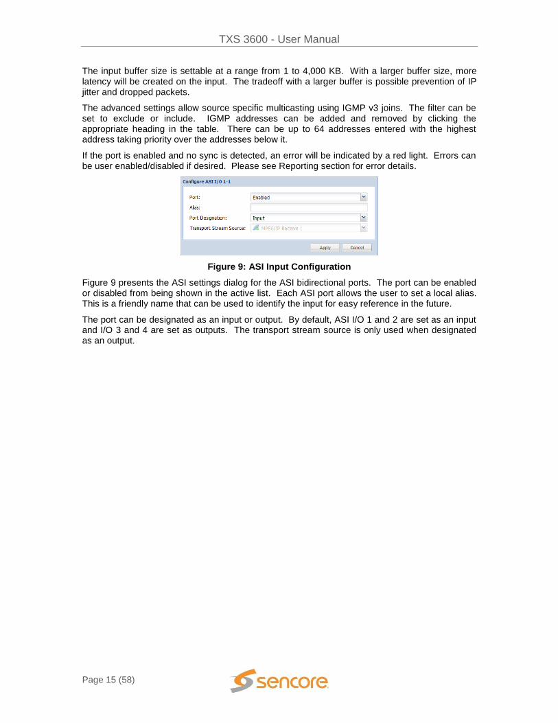
Figure 9: ASI Input Configuration
Figure 9 presents the ASI settings dialog for the ASI bidirectional ports. The port can be enabled or disabled from being shown in the active list. Each ASI port allows the user to set a local alias. This is a friendly name that can be used to identify the input for easy reference in the future.
The port can be designated as an input or output. By default, ASI I/O 1 and 2 are set as an input and I/O 3 and 4 are set as outputs. The transport stream source is only used when designated as an output.
TXS 3600 - User Manual
Page 16 (58)
Transcoder Settings
The Transcoder Settings section focuses around the transcoding or processing as shown in the middle of the individual platform screen. Depending on the number of channels in the chassis, a different number of channels will be shown in the interface.
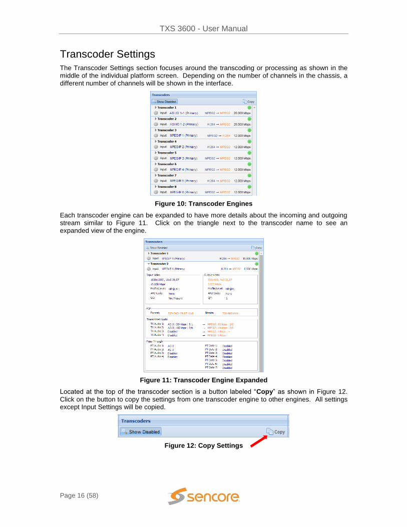
Figure 10: Transcoder Engines
Each transcoder engine can be expanded to have more details about the incoming and outgoing stream similar to Figure 11. Click on the triangle next to the transcoder name to see an expanded view of the engine.
Figure 11: Transcoder Engine Expanded
Located at the top of the transcoder section is a button labeled “Copy” as shown in Figure 12. Click on the button to copy the settings from one transcoder engine to other engines. All settings except Input Settings will be copied.
Figure 12: Copy Settings

TXS 3600 - User Manual
Page 17 (58)
Figure 13 shows the Transcoder Engine Copy dialog box that allows the user to select which transcoder settings would like to be copied from and which transcoders those settings would like to be copied to.
Figure 13: Transcoder Engine Copy
To configure the transcoder for the incoming stream and encoding parameters click on the Cog located directly under the triangle for each individual transcoder engine.
Figure 14: Transcoder Service Settings
Figure 14 is a representation of the settings for a transcoder engine.
On the bottom left of the configuration is a “Reset” button. This will reset (reboot) the individual transcoder for the engine currently open. This will not interrupt any other transcoders in the TXS that are running.

TXS 3600 - User Manual
Page 18 (58)
Figure 15: General Settings
The “General Settings” allow a transcoder to be enabled or disabled. The alias is a friendly name that can be used to identify the input for easy reference. The output TS rate is the bitrate for the transport stream being sent to the outgoing ASI and/or IP port(s).
Figure 16: Input Settings
“Input Settings” provides the ability to select the desired input for the transcoder engine. For the selection to take effect, press the “Apply” button on the right of the selection box, and the available services will be displayed for the Primary Input. To view the services for the Backup input, press “Switch to Backup Input”.
- “Mute on Error” will turn off the output TS if a transcoder error occurs. - “Failover to Backup” sets which conditions the transcoder will switch from the
Primary Input to the Backup Input. These conditions include: Manual Only, On Transcode Error, and On Primary TS Loss.
- “Restore to Primary” sets which conditions the transcoder will switch from the Backup Input to the Primary input. These conditions include: Manual Only, On Primary TS Restored, On Transcode Error, and On Backup TS Loss.
- “Switchover Interval” sets the amount of time the transcoder will wait before switching between the Primary and Backup Inputs after the Failover or Restore condition has occurred. The interval can be set between 1 to 20 seconds.
Figure 17: Available Services
“Available Services” displays all services within the transport stream for the Active Input. The Active Input is displayed at the top of this selection box. The service list can be updated, by pressing “Refresh” on the right.
TXS 3600 - User Manual
Page 19 (58)
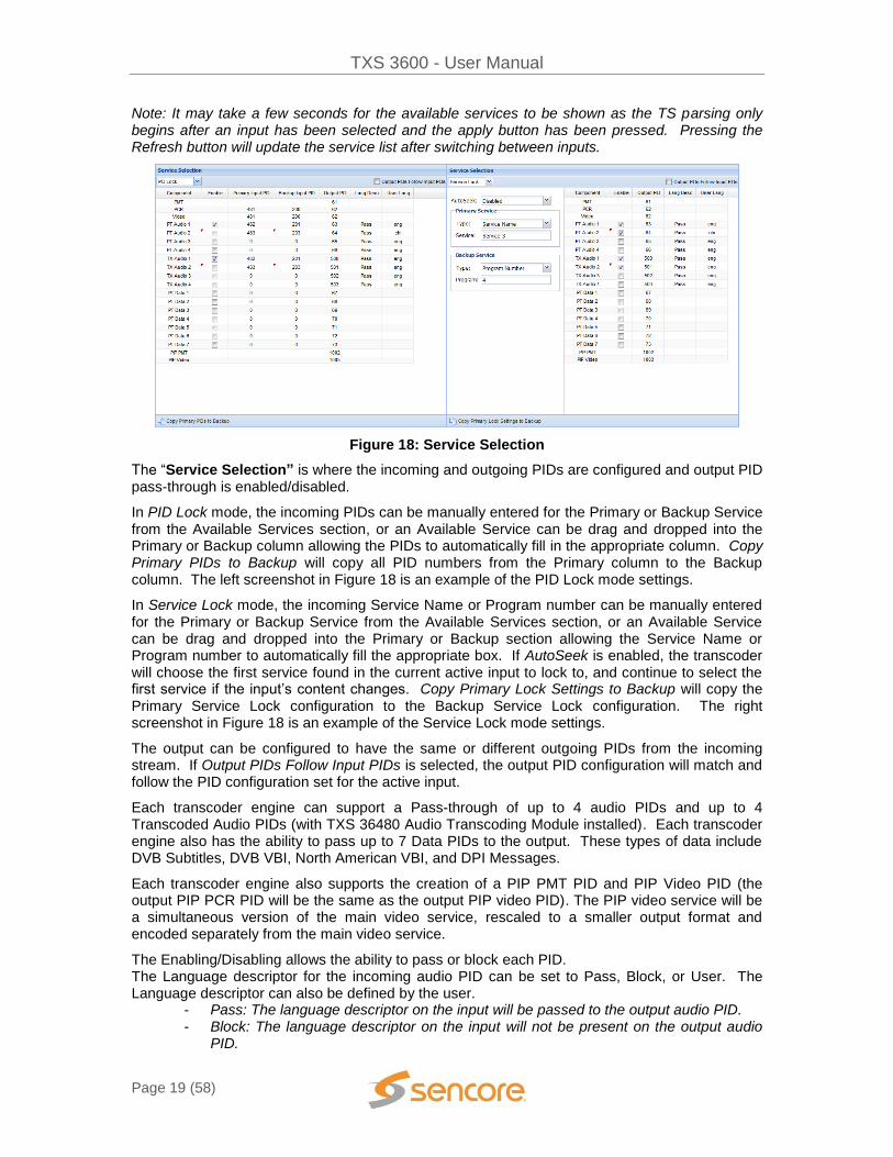
Note: It may take a few seconds for the available services to be shown as the TS parsing only begins after an input has been selected and the apply button has been pressed. Pressing the Refresh button will update the service list after switching between inputs.
Figure 18: Service Selection
The “Service Selection” is where the incoming and outgoing PIDs are configured and output PID pass-through is enabled/disabled.
In PID Lock mode, the incoming PIDs can be manually entered for the Primary or Backup Service from the Available Services section, or an Available Service can be drag and dropped into the Primary or Backup column allowing the PIDs to automatically fill in the appropriate column. Copy Primary PIDs to Backup will copy all PID numbers from the Primary column to the Backup column. The left screenshot in Figure 18 is an example of the PID Lock mode settings.
In Service Lock mode, the incoming Service Name or Program number can be manually entered for the Primary or Backup Service from the Available Services section, or an Available Service can be drag and dropped into the Primary or Backup section allowing the Service Name or Program number to automatically fill the appropriate box. If AutoSeek is enabled, the transcoder will choose the first service found in the current active input to lock to, and continue to select the first service if the input’s content changes. Copy Primary Lock Settings to Backup will copy the Primary Service Lock configuration to the Backup Service Lock configuration. The right screenshot in Figure 18 is an example of the Service Lock mode settings.
The output can be configured to have the same or different outgoing PIDs from the incoming stream. If Output PIDs Follow Input PIDs is selected, the output PID configuration will match and follow the PID configuration set for the active input.
Each transcoder engine can support a Pass-through of up to 4 audio PIDs and up to 4 Transcoded Audio PIDs (with TXS 36480 Audio Transcoding Module installed). Each transcoder engine also has the ability to pass up to 7 Data PIDs to the output. These types of data include DVB Subtitles, DVB VBI, North American VBI, and DPI Messages.
Each transcoder engine also supports the creation of a PIP PMT PID and PIP Video PID (the output PIP PCR PID will be the same as the output PIP video PID). The PIP video service will be a simultaneous version of the main video service, rescaled to a smaller output format and encoded separately from the main video service.
The Enabling/Disabling allows the ability to pass or block each PID. The Language descriptor for the incoming audio PID can be set to Pass, Block, or User. The Language descriptor can also be defined by the user.
- Pass: The language descriptor on the input will be passed to the output audio PID. - Block: The language descriptor on the input will not be present on the output audio
PID.

TXS 3600 - User Manual
Page 20 (58)
- User: The user will be able to specify a three-character language for the audio channel that will be inserted into the language descriptor on the output audio PID.
Figure 19: Transcoder Video and Service Information Settings
The Video and Service Information settings are found on the second tab as shown in Figure 19. This tab is broken down into 3 panes:
1) Video Settings 2) Advanced Video Settings 3) PSI Settings
Figure 20: Transcoder Video Settings
The video encoding settings are found on the first pane as shown in Figure 20.

TXS 3600 - User Manual
Page 21 (58)
Figure 21: General Video Settings
The “General” section includes overall settings for the encoder side of the main service of the transcoder engine. The settings and options are listed below.
- Compressed Video Standard: the encoded video codec of the main service
MPEG-2 H.264 (If License Enabled)
- Format Mode: the automatic or manual setting of resolution and frame rate of the main service
Native (output matches input) Manual (defined in manual format)
- Manual Format: the output resolution, frame rate, and aspect ratio of the main service
Note: Depending on input resolution, some output resolutions will not be allowed. For example upconverting from SD 720x480 29.97i to HD 1920x1080i 30 is NOT supported, whereas cross-converting from 720p to 1080i IS supported.
- Display Mode: how the video of the main service will be displayed when outputting SD resolutions
Center-Cut Letterbox Anamorphic
- Auto AFD: if AFD is present on the input, the output video of the main service will be displayed according to the AFD code
Enabled (the output display mode is selected according to the input AFD code) Disabled (will disregard the incoming AFD code)
- Video Bitrate: video can be selected to be a constant or variable rate for the main video service
Constant Variable (Capped at a maximum rate)
- Constant Bitrate: if constant video bitrate is selected, rate in Mbps of main video service encoded (0.1 – 30 Mbps)
- Max Bitrate: if variable video bitrate is selected, maximum rate in Mbps of main video service encoded (0.1 – 30 Mbps)
- Target Quantization Parameter: is the index used to derive a scaling matrix and quality of the main video service for the targeted variable bitrate. The target QP regulates how much spatial detail is saved. When QP is very small, almost all that

TXS 3600 - User Manual
Page 22 (58)
detail is retained. As QP is increased, some of that detail is aggregated so that the bit rate drops, but at the price of some increase in distortion and some loss of quality.
MPEG-2 Range: 2-31 H.264 Range: 2-63
Figure 22: User Data Pass-through
The user data pass-through enables/disables the pass-through of the AFD code and Closed Captioning on the main service Video PID. The CC Pass-Through Mode allows the user to output Closed Captioning data in SCTE21/ATSC or SCTE20 for the MPEG-2 output codec. If the output codec is set to H.264, the output captions will be in SCTE21/ATSC regardless of this setting.
Figure 23: PIP Video Settings
The “PIP Settings” section includes overall settings for the encoder side of the smaller format picture-in-picture service of the transcoder engine. The settings and options are listed below.
- Codec: the encoded video codec of the PIP service
MPEG-2 H.264
- Manual Format: the output resolution, frame rate, and aspect ratio of the PIP service
Note: Framerate conversion is not supported for PIP.
- Bitrate: rate in kbps of PIP video service encoded (100 – 1000 kbps)

TXS 3600 - User Manual
Page 23 (58)
Figure 24: Transcoder Advanced Video Settings
The advanced video encoding settings are found on the second pane as shown in Figure 24.
Figure 25: Video Filtering Settings
The advanced section of the video encoding allows for setting the video filtering for the main service of the transcoder as shown in Figure 25.
- Scene Detection: forces changes to the GOP structure if a scene change is detected allowing for clean transitions
- Fade Detection: forces changes to the GOP structure if a fade is detected allowing for smooth transitions
- Pre-Deblocking Filter: detects blocking artifacts in video frames and reduces them by applying a selected filter.
Range: 0 (Off) – 3 (Maximum) - Skin Tone Detection: emphasis around the detection of skin tones when encoding
Range: 0 (Off) – 8 (Lowest Quantization on skin tone)
Figure 26: Video Picture Structure Settings
The video picture structure settings are shown in Figure 26.

TXS 3600 - User Manual
Page 24 (58)
- GOP Size: Indicates the size of the GOP and how often I frames are inserted into the video stream. The GOP range is 1 to 300 in size.
- GOP Structure: The option between Dynamic and Static are selectable allowing the GOP size to fluctuate or maintain with the video being encoded. Note: If Scene Detection and/or Fade Detection are enabled, detection of these scenarios will force a change in the GOP sizes even with static GOPs.
- Min/Max/Static GOP Structure: Provides the structure for the GOP. I IP IPB IPBB IPBBB IPBBBB (h.264 only) IPBBBBB (h.264 only)
- GOP Open/Closed: Open GOPs allow B-Frames to get information from previous or forthcoming I/P Frames. Closed GOPs only need to reference previous frames making each GOP self-contained.
- IDR Frequency: Instantaneous decoder refresh frame interval. This setting defines how often I-frames are marked as IDR frames. Input range is 0 to 255. When set to 1, every I-frame is an IDR frame.
Figure 27: Microsoft Mediaroom
The TXS 3600 is Microsoft Mediaroom Ready. By selecting “Yes” to force MM Profile / Level, the Microsoft Mediaroom required Profile and Level will be set for the output Video PID.
Figure 28: PSI Settings
The PSI encoding settings are found on the third pane as shown in Figure 28. These settings allow the transcoder to pass-through or manually change the Service Information (SI) for the output TS.
TXS 3600 - User Manual
Page 25 (58)
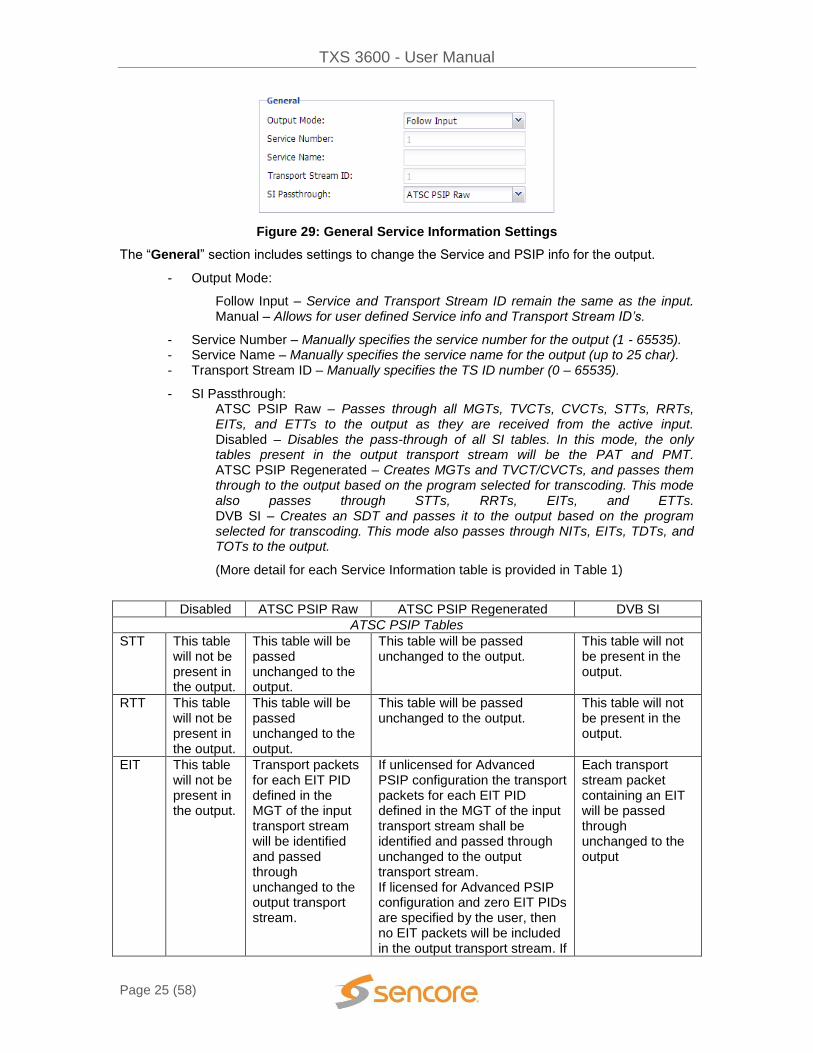
Figure 29: General Service Information Settings
The “General” section includes settings to change the Service and PSIP info for the output.
- Output Mode:
Follow Input – Service and Transport Stream ID remain the same as the input. Manual – Allows for user defined Service info and Transport Stream ID’s.
- Service Number – Manually specifies the service number for the output (1 - 65535). - Service Name – Manually specifies the service name for the output (up to 25 char). - Transport Stream ID – Manually specifies the TS ID number (0 – 65535).
- SI Passthrough: ATSC PSIP Raw – Passes through all MGTs, TVCTs, CVCTs, STTs, RRTs, EITs, and ETTs to the output as they are received from the active input. Disabled – Disables the pass-through of all SI tables. In this mode, the only tables present in the output transport stream will be the PAT and PMT. ATSC PSIP Regenerated – Creates MGTs and TVCT/CVCTs, and passes them through to the output based on the program selected for transcoding. This mode also passes through STTs, RRTs, EITs, and ETTs. DVB SI – Creates an SDT and passes it to the output based on the program selected for transcoding. This mode also passes through NITs, EITs, TDTs, and TOTs to the output.
(More detail for each Service Information table is provided in Table 1)
Disabled ATSC PSIP Raw ATSC PSIP Regenerated DVB SI
ATSC PSIP Tables
STT This table will not be present in the output.
This table will be passed unchanged to the output.
This table will be passed unchanged to the output.
This table will not be present in the output.
RTT This table will not be present in the output.
This table will be passed unchanged to the output.
This table will be passed unchanged to the output.
This table will not be present in the output.
EIT This table will not be present in the output.
Transport packets for each EIT PID defined in the MGT of the input transport stream will be identified and passed through unchanged to the output transport stream.
If unlicensed for Advanced PSIP configuration the transport packets for each EIT PID defined in the MGT of the input transport stream shall be identified and passed through unchanged to the output transport stream. If licensed for Advanced PSIP configuration and zero EIT PIDs are specified by the user, then no EIT packets will be included in the output transport stream. If
Each transport stream packet containing an EIT will be passed through unchanged to the output

TXS 3600 - User Manual
Page 26 (58)
“n” EIT PIDs are specified, then TS packets for EIT-0 through EIT-(n-1), as defined in the MGT, will be passed through unchanged to the output transport stream.
ETT This table will not be present in the output.
Transport packets for each channel ETT and event ETT PID defined in the MGT of the input transport stream will be identified and passed through unchanged to the output transport stream.
If unlicensed for Advanced PSIP configuration the transport packets for each channel ETT and event ETT PID defined in the MGT of the input transport stream shall be identified and passed through unchanged to the output transport stream. If licensed for Advanced PSIP configuration and zero ETT PIDs are specified by the user, then no ETT packets will be included in the output transport stream. If “n” ETT PIDs are specified, then TS packets for ETT-0 through ETT-(n-1), as defined in the MGT, will be passed through unchanged to the output transport stream.
This table will not be present in the output.
TVCT This table will not be present in the output.
This table will be passed unchanged to the output.
If licensed for Advanced PSIP configuration and the PSIP Mode is set to “Manual” then the major_channel_number, minor_channel_number, and modulation_mode will be user defined. If not licensed for Advanced PSIP configuration the TVCT will be regenerated using the user defined transport_stream_id, short_name, and program number. num_channels_in_section will be set to “1” and carrier_frequency will be set to all zeros.
This table will not be present in the output.
CVCT This table will not be present in the output.
This table will be passed unchanged to the output.
If not licensed for Advanced PSIP configuration the CVCT will be regenerated using the user defined transport_stream_id, short_name, and program number. num_channels_in_section will be set to “1” and carrier_frequency will be set to all zeros. If licensed for Advanced PSIP configuration and the PSIP
This table will not be present in the output.

TXS 3600 - User Manual
Page 27 (58)
Mode is set to “Manual” then the major_channel_number, minor_channel_number, and modulation_mode will be user defined.
MGT This table will not be present in the output.
This table will be passed unchanged to the output.
An MGT will be present on the output transport stream and the fields will be defined by the other tables present on the output transport stream.
This table will not be present in the output.
DVB SI Tables
SDT This table will not be present in the output.
This table will not be present in the output.
This table will not be present in the output.
The SDT will be regenerated using the user defined transport_stream_id, short_name, and program number
NIT This table will not be present in the output.
This table will not be present in the output.
This table will not be present in the output.
Each transport stream packet containing a NIT will be passed through unchanged to the output.
EIT This table will not be present in the output.
This table will not be present in the output.
This table will not be present in the output.
Each transport stream packet containing an EIT will be passed through unchanged to the output.
TDT This table will not be present in the output.
This table will not be present in the output.
This table will not be present in the output.
Each transport stream packet containing a TDT will be passed through unchanged to the output.
TOT This table will not be present in the output.
This table will not be present in the output.
This table will not be present in the output.
Each transport stream packet containing a TOT will be passed through unchanged to the output.
Table 1: SI Passthrough Information
TXS 3600 - User Manual
Page 28 (58)
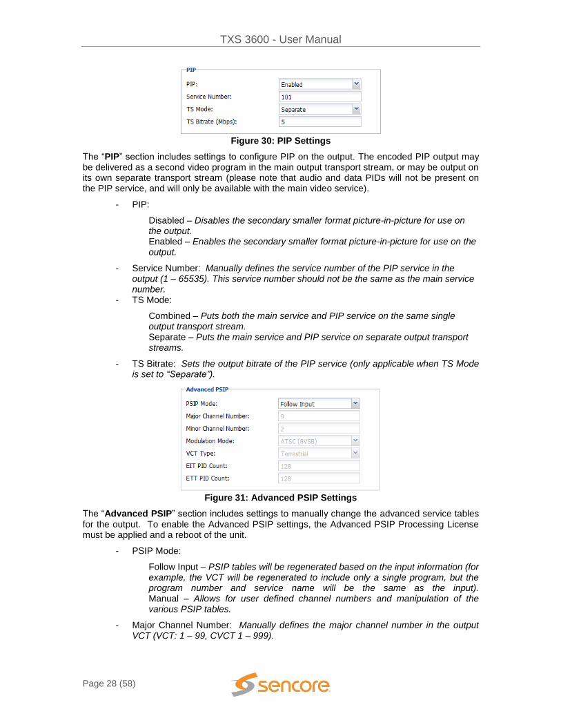
Figure 30: PIP Settings
The “PIP” section includes settings to configure PIP on the output. The encoded PIP output may be delivered as a second video program in the main output transport stream, or may be output on its own separate transport stream (please note that audio and data PIDs will not be present on the PIP service, and will only be available with the main video service).
- PIP:
Disabled – Disables the secondary smaller format picture-in-picture for use on the output. Enabled – Enables the secondary smaller format picture-in-picture for use on the output.
- Service Number: Manually defines the service number of the PIP service in the output (1 – 65535). This service number should not be the same as the main service number.
- TS Mode:
Combined – Puts both the main service and PIP service on the same single output transport stream. Separate – Puts the main service and PIP service on separate output transport streams.
- TS Bitrate: Sets the output bitrate of the PIP service (only applicable when TS Mode is set to “Separate”).
Figure 31: Advanced PSIP Settings
The “Advanced PSIP” section includes settings to manually change the advanced service tables for the output. To enable the Advanced PSIP settings, the Advanced PSIP Processing License must be applied and a reboot of the unit.
- PSIP Mode:
Follow Input – PSIP tables will be regenerated based on the input information (for example, the VCT will be regenerated to include only a single program, but the program number and service name will be the same as the input). Manual – Allows for user defined channel numbers and manipulation of the various PSIP tables.
- Major Channel Number: Manually defines the major channel number in the output VCT (VCT: 1 – 99, CVCT 1 – 999).

TXS 3600 - User Manual
Page 29 (58)
- Minor Channel Number: Manually defines the minor channel number in the output VCT (0 – 999).
- Modulation Mode: Sets the VCT modulation mode (Analog, SCTE Mode 1 (QAM64), SCTE Mode 2 (QAM256), ATSC (8VSB), or ATSC (16VSB)).
- VCT Type: Sets the type of Virtual Channel Table (VCT) for the output TS (Terrestrial or Cable).
- EIT PID Count: Sets the maximum number of EITs to pass from the input to output TS (0 – 128).
- ETT PID Count: Sets the maximum number of ETTs to pass from the input to output TS (0-128).
Located on the top right of the video configuration are presets for various encoding parameters. These presets will adjust settings such as filtering and GOP structure of the encoded output.
Figure 32: Encoding Presets
The video encode preset options are:
- Legacy MPEG2 - Filtering Off - Dynamic GOP Defaults - Static GOP Defaults - Microsoft Mediaroom - Factory Defaults
Figure 33: Transcoder Audio Settings
The Audio Transcode settings are found on the next tab as shown in Figure 33. This menu will only be available if the TXS 3600 has the Audio Transcoding Module installed. Each transcoded audio PID has its own Decode/Encode settings. Click on TX Audio 1, 2, 3, or 4 to change the

TXS 3600 - User Manual
Page 30 (58)
audio transcode settings for the desired output PID. TX Audio 1 refers to the first TX Audio listed in the Service Selection Tab.
Figure 34: Decode Settings
Figure 34 shows the audio Decode Settings for the transcoded audio PID. - Gain: Amplification or attenuation of the decoded audio
The rest of the decode settings are organized by the input audio codec that is being decoded. - AC3 (Dolby Digital):
o Downmix: Summation of the audio channels to: Mono, 2/0 Lo/Ro, 2/0 Lt/Rt o Operational Mode: Compression mode used for the AC3 downmix o Dynamic Range: Limiting the audio level range
- AAC Downmix: Summation of the audio channels to: Mono, Stereo, Disabled* - Linear PCM Downmix: Summation of the audio channels to: Mono, Stereo,
Disabled* - MPEG-2 Downmix: Summation of the audio channels to: Mono, Disabled*
*When this setting is Disabled, the output defaults to Stereo Downmix mode.
Audio encode settings will have different menus for each output codec: AC-3, Dolby Digital Plus, AAC, and MPEG-2.

TXS 3600 - User Manual
Page 31 (58)
Figure 35: AC-3 and Dolby Digital Plus Encode Settings
AC-3 and Dolby Digital Plus encode settings include: - Broadcast Mode: Follows ATSC or DVB Dolby standard specification. - Bitrate: Output audio data rate - Dolby Info: Enabled passes any audio metadata from the input audio PID. Disabled
allows the user to specify audio metadata for the output Audio PID. - DialNorm: Metadata parameter that sets the reference playback level. - Bitstream Mode: Describes the audio program contained within the AC-3 or Dolby
Digital Plus bitstream. - Production Info Exists: Flag in the output audio PID specifying additional metadata
exists for: Mix level, Room Type, Copyright, and Original bitstream. - Mix level: Specifies the monitor level used to mix the program. - Room Type: Describes the size of the control room where mixing occurred. - Copyright: Specifies if the material is copyrighted. - Original Bitstream: Specifies if the material is the original bitstream. - Line Mode DRC: Specifies playback parameters for the program during decoder Line
Mode operation. - RF Mode DRC: Specifies playback parameters for the program during decoder RF
Mode operation.
Note: The defaults are set to DialNorm = -31dB and Line/RF Mode DRC = None. These are based on recommendations in Dolby’s Broadcast Transcoder Reference Guide to maintain NO attenuation when compared to the passthrough audio. So if the received audio is encoded at -24dB (as required by the FCC “CALM” act) using the default settings will result in the output audio level not changing at all.
Figure 36: AAC Encode Settings
AAC Encode Settings include: - Container: Utilizes either ADTS or LOAS (also known as LATM)

TXS 3600 - User Manual
Page 32 (58)
- Profile: Choice of AAC-LC, HE-AACv1, HE-AACv2 - TNS: Temporal Noise Shaping - Bitrate: Output audio data rate - Codec Version: MPEG2 or MPEG4
Figure 37: MPEG-2 Encode Settings
MPEG-2 Encode Settings include: - Stereo Mode: Specify Stereo or Joint Stereo (Dual Mono) - Bitrate: Output audio data rate
Figure 38: Audio Decode Presets
The audio decode preset options are:
- AC3 Transmission - AC3 Monitor

TXS 3600 - User Manual
Page 33 (58)
Output Settings
This section focuses around the IP and ASI settings found on the right column of the individual platform home screen as shown in Figure 39.
All TXS 3600 platforms will have the ability to output ASI and/or IP. Thirty-two IP streams will be available along with ASI ports (not assigned as inputs).
Figure 39: Outputs
Each port can be configured by clicking on the cog associated with the connection.
Figure 40: Configure ASI output
The ASI output configuration is similar to the ASI input if the connector is bidirectional. The ASI output can be enabled/disabled to allow configuration changes without transmitting. The unit alias is a friendly name that can be used to identify the output for easy reference. When designated as an output, the transport stream source or transcoder engine is available to be selected to assign the appropriate output.
TXS 3600 - User Manual
Page 34 (58)
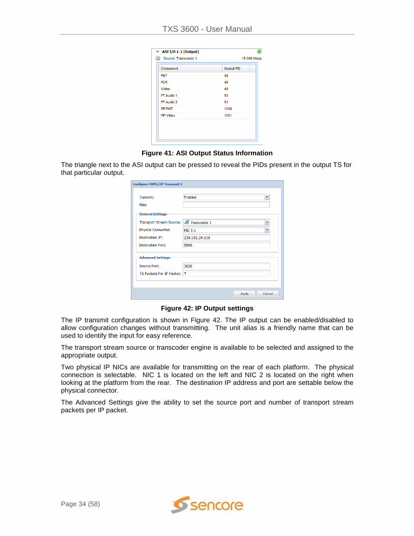
Figure 41: ASI Output Status Information
The triangle next to the ASI output can be pressed to reveal the PIDs present in the output TS for that particular output.
Figure 42: IP Output settings
The IP transmit configuration is shown in Figure 42. The IP output can be enabled/disabled to allow configuration changes without transmitting. The unit alias is a friendly name that can be used to identify the input for easy reference.
The transport stream source or transcoder engine is available to be selected and assigned to the appropriate output.
Two physical IP NICs are available for transmitting on the rear of each platform. The physical connection is selectable. NIC 1 is located on the left and NIC 2 is located on the right when looking at the platform from the rear. The destination IP address and port are settable below the physical connector.
The Advanced Settings give the ability to set the source port and number of transport stream packets per IP packet.

TXS 3600 - User Manual
Page 35 (58)
Figure 43: MPEG/IP Transmit Status Information
The triangle next to the MPEG/IP Transmit can be pressed to reveal the following status information for that particular transmit:
1) Physical Connector 2) Destination IP and Port 3) Source Port 4) TS/IP Packet 5) The PIDs present in the output TS

TXS 3600 - User Manual
Page 36 (58)
Licensing Tab
The license tab is located after the two platforms in the web interface. This page allows the user to license the transcode engines for video and audio encoding.
Figure 44: Licensing Tab
The left column identifies the available/total licenses available for each type of license. The licenses are assigned by dragging and dropping the appropriate license to the desired transcoder engine. Any license can be removed from a transcode engine and re-assigned to a different transcode engine by clicking the “X Remove Licenses” and drag and dropping the license onto a new transcode engine. Each transcoder can be licensed for HD/SD h.264 or MPEG-2 video encoding. When the TXS 36480 Audio Transcoding Module is installed, up to 4 Audio PIDs per transcoder can be licensed. Without any audio encoding licensing, the Audio Transcoding Module can output up to 4 MPEG-2 audio PIDs per transcoder. The Dolby Digital Encoding license enables the ability to encode the output audio PID to AC3 or Dolby Digital Plus. The AAC Encoding license enables the ability to encode the output audio PID to AAC or HE-AAC. The type and number of licenses can be updated and changed with a license key. To find out pricing and how obtain a new license key please contact Sencore. Once a new license key has been obtained, the character string can be copied and pasted into the dialog box as shown in Figure 45 that appears after clicking on the “Update License” button.
Figure 45: License Key Dialog

TXS 3600 - User Manual
Page 37 (58)
Admin Tab
The Admin tab allows system specific settings to be set or modified.
Located directly under the Admin Control Panel are the options for changing Unit Alias, saving Profiles, changing the web GUI Password, downloading the SNMP MIBs, saving Diagnostic file, Rebooting system, Resetting to Factory Defaults, and unit Software Updating.
Unit Alias
Located in the top left corner of the Admin tab is the unit alias. This allows for unique identification of each unit for easy reference.
To change the alias, click on the pencil and paper and a dialog box will appear.
Figure 47: Changing unit alias
Figure 46: Admin tab
TXS 3600 - User Manual
Page 38 (58)
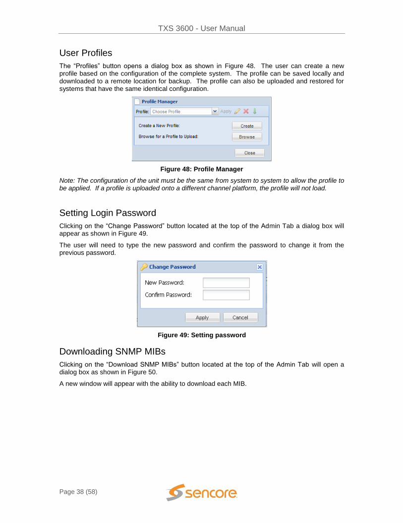
User Profiles
The “Profiles” button opens a dialog box as shown in Figure 48. The user can create a new profile based on the configuration of the complete system. The profile can be saved locally and downloaded to a remote location for backup. The profile can also be uploaded and restored for systems that have the same identical configuration.
Figure 48: Profile Manager
Note: The configuration of the unit must be the same from system to system to allow the profile to be applied. If a profile is uploaded onto a different channel platform, the profile will not load.
Setting Login Password
Clicking on the “Change Password” button located at the top of the Admin Tab a dialog box will appear as shown in Figure 49.
The user will need to type the new password and confirm the password to change it from the previous password.
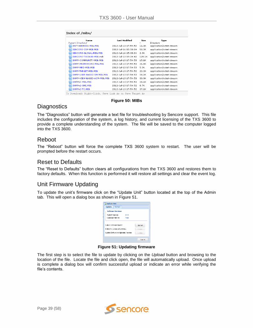
Downloading SNMP MIBs
Clicking on the “Download SNMP MIBs” button located at the top of the Admin Tab will open a dialog box as shown in Figure 50.
A new window will appear with the ability to download each MIB.
Figure 49: Setting password
TXS 3600 - User Manual
Page 39 (58)
Figure 50: MIBs
Diagnostics
The “Diagnostics” button will generate a text file for troubleshooting by Sencore support. This file includes the configuration of the system, a log history, and current licensing of the TXS 3600 to provide a complete understanding of the system. The file will be saved to the computer logged into the TXS 3600.
Reboot The “Reboot” button will force the complete TXS 3600 system to restart. The user will be prompted before the restart occurs.
Reset to Defaults The “Reset to Defaults” button clears all configurations from the TXS 3600 and restores them to factory defaults. When this function is performed it will restore all settings and clear the event log.
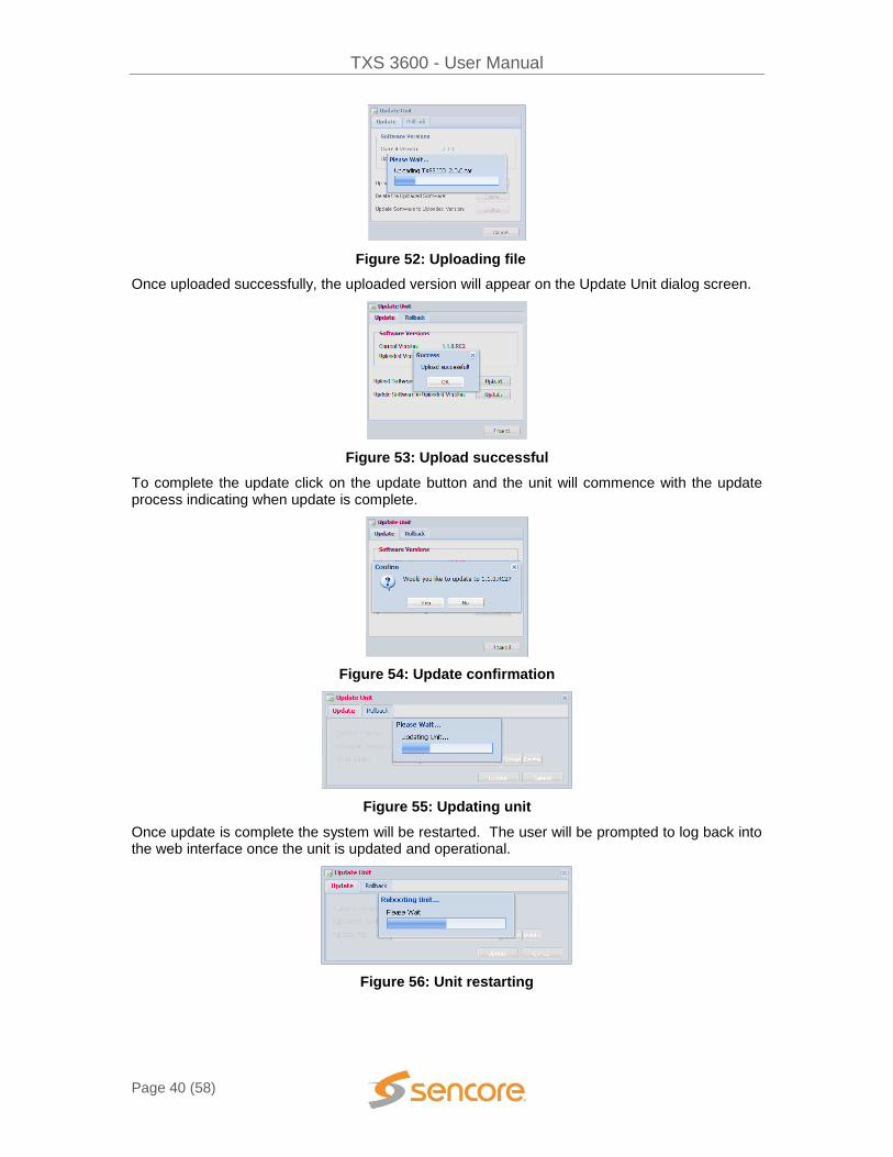
Unit Firmware Updating
To update the unit’s firmware click on the “Update Unit” button located at the top of the Admin tab. This will open a dialog box as shown in Figure 51.
The first step is to select the file to update by clicking on the Upload button and browsing to the location of the file. Locate the file and click open, the file will automatically upload. Once upload is complete a dialog box will confirm successful upload or indicate an error while verifying the file’s contents.
Figure 51: Updating firmware
TXS 3600 - User Manual
Page 40 (58)
Once uploaded successfully, the uploaded version will appear on the Update Unit dialog screen.
Figure 53: Upload successful
To complete the update click on the update button and the unit will commence with the update process indicating when update is complete.
Figure 54: Update confirmation
Figure 55: Updating unit
Once update is complete the system will be restarted. The user will be prompted to log back into the web interface once the unit is updated and operational.
Figure 56: Unit restarting
Figure 52: Uploading file

TXS 3600 - User Manual
Page 41 (58)
Unit Firmware Rollback
The TXS 3600 offers the ability to roll back to the previous version of software that was installed on the unit. The roll back feature will restore the unit back to the previous state before the latest update was performed.
The rollback option is located in the “Update Unit” dialog box under the Rollback Tab as shown in Figure 57.
Network Configuration
In the middle of the Admin Tab, the IP address configuration for the physical ports is shown. The Unit Network Configuration shows the management port’s IP settings. The current status is shown, but can be modified by clicking on the cog located on the left of the status.
When clicking on the configure cog a dialog box to change IP settings similar to Figure 58 will be presented. For the MPEG over IP configuration, only IP, Subnet, and Gateway are allowed to be set. The management port supports DHCP or Static IP addressing.
If set to DHCP, the user can enter a hostname to easily access the box by the name rather than the IP address given by DHCP. When the mode is set to static, the user has to set the IP, Subnet, and Gateway Addresses.
Figure 57: Firmware rollback
Figure 58: Network configuration

TXS 3600 - User Manual
Page 42 (58)
Date/Time
The user has the ability to set the local time for the TXS 3600 transcoder. The time can be configured using an NTP server by entering the address to synchronize the time and date or it can be entered manually as shown in Figure 60.
SNMP Communities
The communities for the SNMP management can be changed from the default of “public” for Read-Only Communities and “private” for Read-Write Communities.
SNMP Trap Managers
The managers for the SNMP management can be entered or removed by clicking on “Configure SNMP Managers”.
Figure 59: IP settings
Figure 60: Date/Time configuration
Figure 61: SNMP communities

TXS 3600 - User Manual
Page 43 (58)
Figure 62: SNMP managers
Unit Identifier
Each chassis comes with the ability to be easily identified with a blinking blue indicator when enabled. This blue blinking light is visible in both the front and back of the chassis. To enable the UID in the web interface, it is located on the top right side of the Admin tab as shown in Figure 63.
Figure 63: Unit Identifier
The UID can be turned on/off from the front panel by using the following sequence: UP Arrow RIGHT Arrow DOWN Arrow LEFT Arrow UP Arrow Enter Button

TXS 3600 - User Manual
Page 44 (58)
Reporting Tab
The reporting tab contains the status and alarm indications for the TXS 3600 transcoder. The alarms, logs, and alarm configuration are separated by individual menus and configurable to the exact scenario a user desires to monitor.
Alarms
The Alarms tab is the first screen shown under the reporting tab. The “Configure” button opens a configuration screen as shown in Figure 65. All of the alarms in the unit are capable of being enabled or disabled from being generated. Each condition can be configured as an error or information situation under log severity.
Figure 64: Reporting tab
Figure 65: Alarm configuration

TXS 3600 - User Manual
Page 45 (58)
Category Name Description of Error
System 12V Supply Error Unable to detect 12V from power supply
System 3.3V Supply Error Unable to detect 3.3V from power supply
System 5V Supply Error Unable to detect 5V from power supply
Platform AFD Code Not Present The system is unable to find any active format display information in the incoming stream.
Platform ASI I/O TS Sync Error No ASI sync with the transport stream
Platform Audio Encoding Bitrate Out of Range Encoding Bitrate is invalid according to the number of output channels
Platform Audio Input Error Unsupported or no audio present on PID
Platform Audio Transcoding Error Audio transcoder has logged 2.5 seconds of no audio data processed
Platform Backup Input Active The backup input is the active input for the transcoder
Platform Data PID Error Data PID not found
Platform Duplicate Program Number Error The output program number is the same for both the main and PIP services for a given transcoder.
System Fan Error A fan failure has been detected
Platform IP Receive TS Packets Not Received Error
Indicates MPEG/IP data interface is not receiving any TS Packets
Platform IP Receive TS Sync Error Indicates the MPEG/IP data interface has an error with synchronization
Platform IP Transmit TS Packet Lost Error The MPEG/IP data interface has lost a packet
Platform IP Transmit TS Sync Error The MPEG/IP data interface has lost TS synchronization.
Platform Input TS Not Present The presence of a transport stream is not detected.
Platform No Services Found Error No Service is found in the input TS
Platform Output TS Not Present No transport stream is present at the output
Platform Output TS Rate May Be Set Too Low Indicates the TS rate is too low to allow all of the video, audio and data to be in the transmitting stream of the main service
Platform PCR PID Error The transcoder engine is unable to synchronize with the video because no PCR is found.
Platform PIP Output TS Too Low Indicates the PIP TS rate is too low to allow all of the PIP video data and table data to be in the transmitting stream
Platform PIP Unsupported Format Conversion The current configuration of transcoding of the PIP service is not supported
Platform PIP Video PID Error The output PIP video PID conflicts with another configured output PID for a given transcode engine
Platform Pass-through Audio PID Error Audio PID set to Pass-through is not found
System Power Supply Error An error with one of the power supplies
Platform Service Not Found Error Service set to transcode is not found within input TS
System Temperature Error Internal temperature is outside the range of 0 to 45 Celsius
Platform Transcoded Audio PID Error Audio PID set to Transcode is not found

TXS 3600 - User Manual
Page 46 (58)
Platform Transcoder Reset A user has initiated a transcoder reset
Platform Unsupported Format Conversion The current configuration of transcoding of the main service is not supported
Platform Unsupported Input Format The detected input format is not supported in the TXS platform
Platform Video Input Error An error relating to the video on the input
Platform Video PID Error A PID conflict with the video as a presence of the PID is detected but no video is present possible the PID is of another type
Figure 66: Alarm descriptions
Logs & Events
The logs can be viewed under the reporting tab by clicking the “Logs” button at the top of the Report Control Panel. Each error/event can be enabled or disabled to be logged for reference. On the left side of the logs screen the download button is capable of saving the log files for troubleshooting purposes.
Figure 67: Logs view
All events can be enabled/disabled as shown in Figure 68 by clicking on the “Configure” button.

TXS 3600 - User Manual
Page 47 (58)
Figure 68: Configure events Category Name Description of Event
Date/Time Change
The unit’s date/time has been changed Date/Time Change
NTP Update The unit’s date/time was updated by the NTP server NTP Update
Unit Bootup The unit has been loaded Unit Bootup
Unit Shutdown The unit was shutdown Unit Shutdown
Figure 69: Event descriptions
SNMP Trap Configurations
The SNMP trap configurations can be edited under the reporting tab by clicking the “Configurations” at the top-right of the report control panel. All conditions can be enabled/disabled from sending SNMP Traps.
The SNMP trap manager IP addresses can be added under the admin tab.

TXS 3600 - User Manual
Page 48 (58)
About Tab
The About page provides the software and hardware details and versions for the equipment found within the TXS 3600 transcoder. This information will be asked when talking to technical support. The contact information is also provided for reaching Sencore.
Figure 70: About Tab
System Recovery The TXS 3600 system has the ability to recover from complete image corruption. The system recovery allows a user to start the platform into a prompt where a software update will allow the system to be installed in the event all other images will not work.
To use the system recovery, hold two buttons (any 2 buttons) when power is applied to the unit for at least 20 seconds.
The unit will boot into recovery mode. The user can press the “Enter” button on the front panel to configure the IP address if necessary. A web browser can then be used to connect to the system and apply an update to the unit.

TXS 3600 - User Manual
Page 49 (58)
OPTIONS ↕ >ACTIVE ERRORS NETWORK SETTINGS TIME UNIT TEMPERATURE ABOUT
ACTIVE ALARMS ↕ >ASI I/O TS SYNC ERRROR – LOC: P UNSUPPORTED INPUT FORMAT – LOC: CC NOT PRESENT – LOC: PLATFORM
SENCORE TXS3600 ↔↕ ACTIVE: 8 ALIAS
IDLE: 0 192.168.1.111 TX 2-4: MPEG-2 -> H264
8 MBPS
Using the Front Panel on the TXS 3600
This section of the user manual overviews the menus and operation of the TXS 3600 transcoder using the front panel for control. All functionality of the front panel is also accessible through the Web User Interface.
FP Options and Settings
The options settings allow the viewing of active errors, the configuring/viewing of network settings and system time. The About section provides software versioning and serial numbers.
Active Alarms
All active alarms are shown with the ability to scroll right using the arrow key to view the entire error detail.
Once the TXS 3600 is finished loading, depending on the number of channels, a screen similar to the one on the right will appear. The bottom 2 rows of text will cycle through the transcoders giving status update.

TXS 3600 - User Manual
Page 50 (58)
UNIT NETWORK STATUS ↕ >IP ADDRESS: 10.0.15.6 SUBNET MASK: 255.255.0.0 GATEWAY: 10.0.1.3 DHCP MODE: DISABLED HOSTNAME: TXS1 MAC: 00:AB:CD:EF:GH:I7
TIME ↕ >TIME: 2010/8/12 03:27:48 SOURCE: NTP SERVER ADDRESS: 10.0.1.23
TIME ↕ TIME: 2010/8/12 03:27:48 SOURCE: MANUAL >SET DATE: 2010/8/12 SET TIME: 03:27:48
Network Settings
The unit network menu provides status for current IP address. If DHCP is enabled, the current IP address is shown. If static is enabled, press enter to manually change the IP Address, Subnet Mask, and Gateway. To enable/disable DHCP press the “Enter” button while in the Unit Network Status menu and “Enter” again while the cursor is on “DHCP Mode” in the Network Configuration menu.
The hostname allows a user to remotely connect to the TXS 3600 transcoder with a Web Browser by simply typing the hostname and not the IP address into the web browser. This is helpful when used on DHCP networks. To edit the hostname press the “Enter” button while cursor is on “Hostname” in the Unit Network Status and “Enter” again on Hostname in the Network Configuration menu.
Unit Time
The time and date for the unit can be set manually or synchronized with an NTP server. The date and time are used for storing the correct time for alarms and logs for accurate representation of when the occurrence took place.

TXS 3600 - User Manual
Page 51 (58)
ABOUT ↕ >IMAGES HARDWARE SERIAL: 1234567
SOFTWARE VERSIONS ↕ PRODUCT: TXS 3600 VERSION: 2.0.0
ABOUT: HARDWARE ↕ >BOARD 1149 BOARD 1182 BAORD 1184
UNIT TEMPERATURE ↕
32.25C (90.05F)
Unit Temperature
Sample Unit Temperature
FP About
The about screen provides information for software and hardware installed in the TXS 3600 transcoder. This information will be asked when talking to technical support.
About Software
Sample Software Versions
About Hardware
Sample About Hardware

TXS 3600 - User Manual
Page 52 (58)
Appendix
Specifications
TXS 3600 Base Unit Includes: Display, keypad, embedded controller, Chassis/case, Power Supply/line cord System – Display Type: LCD Display Configuration: 240 pixels by 64 pixels Keypad: Snap-domeMembrane Configurations Allowed: Single Platform Dual Platform Remote Operation/Update Interface – Type: Ethernet, 10/100 Rear panel indicators: Link (Green LED), Activity (Amber LED) Connector: RJ45 Front Panel Indicators – UID LED: Blue indicates the Unit Identifier is turned on Error LED: Red indicates error is occurring OFF indicates no errors detected Monitor and Control Interfaces – Web server GUI HTTP via web browser for Control & Monitoring Front Panel Yes IP Configuration & Monitoring SNMP Yes Control & Monitoring AC Power – Operating Voltage: 95-135 VAC or 180-265 VAC Current Draw/Power: 275 Watts Frequency: 47-63Hz Line Cord: Detachable, 3-prong Redundancy: Dual Hot Swappable, Load Sharing DC Power –
Operating Voltage: -40VDC to -70VDC Max Current Draw/Power: 10A / 250W Redundancy: Dual Hot Swappable, Load Sharing
General – RoHS Compliant: Yes Operating Temperature: 0 to 45 degrees C Operating Humidity: <95% Non-Condensing Cooling: Forced air, front intake, rear exhaust Temperature monitor: Fan failure, internal temperature sensor Size: Height = 1RU (13/4”), Width = 19”, Depth = 19” 19 in. rack mountable, removable ears Rack clips and screws included Weight: ~9.5 lbs. (base unit) ~12.75 lbs. (Fully Loaded) Pollution Degree: 2 Installation Category: II Grounding Post: On chassis
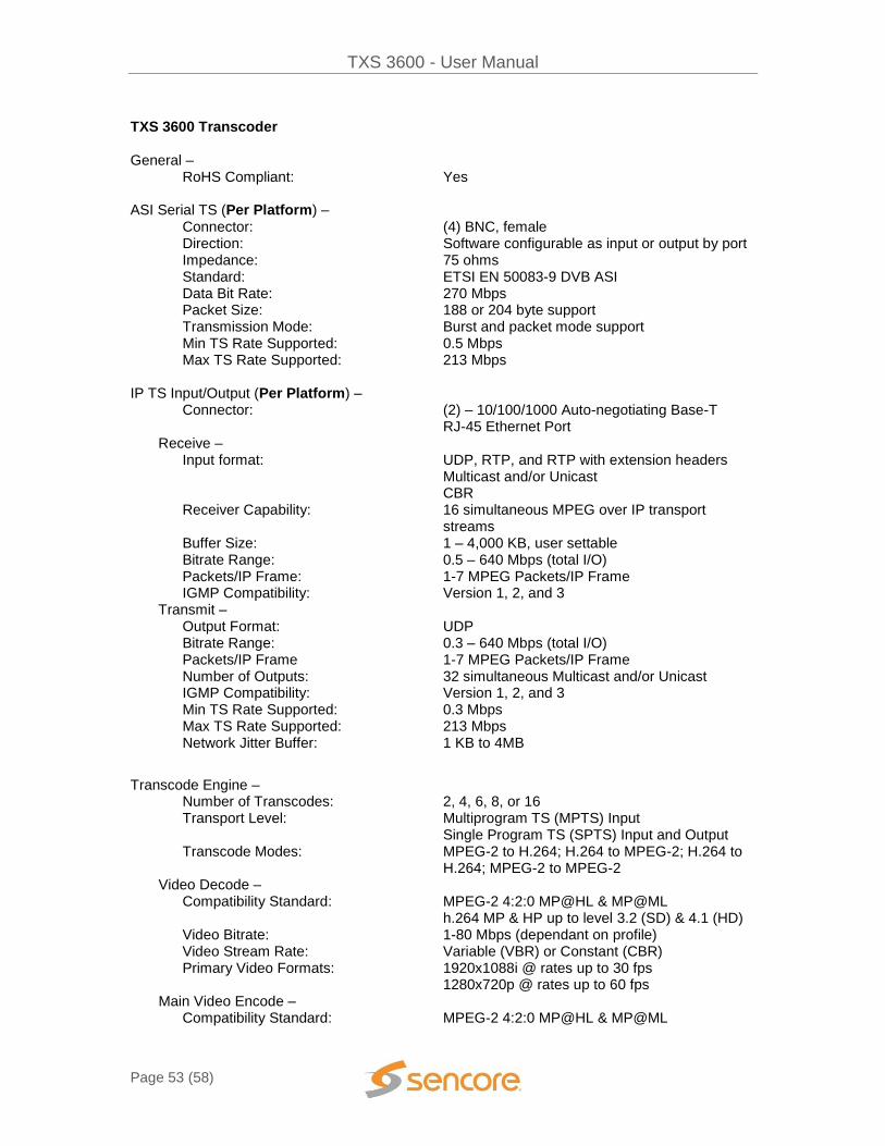
TXS 3600 - User Manual
Page 53 (58)
TXS 3600 Transcoder General – RoHS Compliant: Yes ASI Serial TS (Per Platform) – Connector: (4) BNC, female Direction: Software configurable as input or output by port Impedance: 75 ohms Standard: ETSI EN 50083-9 DVB ASI Data Bit Rate: 270 Mbps Packet Size: 188 or 204 byte support Transmission Mode: Burst and packet mode support Min TS Rate Supported: 0.5 Mbps Max TS Rate Supported: 213 Mbps IP TS Input/Output (Per Platform) – Connector: (2) – 10/100/1000 Auto-negotiating Base-T RJ-45 Ethernet Port Receive – Input format: UDP, RTP, and RTP with extension headers Multicast and/or Unicast CBR Receiver Capability: 16 simultaneous MPEG over IP transport
streams Buffer Size: 1 – 4,000 KB, user settable Bitrate Range: 0.5 – 640 Mbps (total I/O) Packets/IP Frame: 1-7 MPEG Packets/IP Frame IGMP Compatibility: Version 1, 2, and 3 Transmit – Output Format: UDP Bitrate Range: 0.3 – 640 Mbps (total I/O) Packets/IP Frame 1-7 MPEG Packets/IP Frame Number of Outputs: 32 simultaneous Multicast and/or Unicast IGMP Compatibility: Version 1, 2, and 3 Min TS Rate Supported: 0.3 Mbps Max TS Rate Supported: 213 Mbps Network Jitter Buffer: 1 KB to 4MB
Transcode Engine – Number of Transcodes: 2, 4, 6, 8, or 16 Transport Level: Multiprogram TS (MPTS) Input
Single Program TS (SPTS) Input and Output Transcode Modes: MPEG-2 to H.264; H.264 to MPEG-2; H.264 to
H.264; MPEG-2 to MPEG-2 Video Decode –
Compatibility Standard: MPEG-2 4:2:0 MP@HL & MP@ML h.264 MP & HP up to level 3.2 (SD) & 4.1 (HD)
Video Bitrate: 1-80 Mbps (dependant on profile) Video Stream Rate: Variable (VBR) or Constant (CBR) Primary Video Formats: 1920x1088i @ rates up to 30 fps 1280x720p @ rates up to 60 fps Main Video Encode – Compatibility Standard: MPEG-2 4:2:0 MP@HL & MP@ML

TXS 3600 - User Manual
Page 54 (58)
H.264 4:2:0 [email protected] & [email protected]
Native Resolution/Frame Rates/Aspect Ratio Supported:
1920 x 1080i @ 25, 29.97, & 30 16x9
1920 x 1080p @ 23.97, 24, 25, 29.97, & 30 16x9
1440 x 1080i @ 25, 29.97, & 30 16x9 1440x1080p @ 23.97, 24, 25, 29.97, & 30 16x9 1280 x 1080i @ 25, 29.97, & 30 16x9 1280 x 1080p @ 23.97, 24, 25, 29.97, & 30 16x9
1280 x 720p @ 50, 59.94 & 60 16x9
960x720p @ 50, 59.94 & 60 16x9
960x720p @ 29.97 4x3
720 x 576i @ 25 16x9/4x3
704 x 576i @ 25 16x9/4x3
640 x 576i @ 25 16x9/4x3
544 x 576i @ 25 16x9/4x3
528 x 576i @ 25 16x9/4x3
480 x 576i @ 25 16x9/4x3
352 x 576i @ 25 16x9/4x3
720 x 480i @ 29.97 16x9/4x3 720 x 480p @ 29.97 4x3 704 x 480i @ 29.97 16x9/4x3
640 x 480i @ 29.97 16x9/4x3
640 x 480p @ 29.97 4x3
544 x 480i @ 29.97 16x9/4x3
528 x 480i @ 29.97 16x9/4x3
480 x 480i @ 29.97 16x9/4x3
352 x 480i @ 29.97 16x9/4x3
640x360p @ 29.97 16x9/4x3
352 x 288p @ 25 16x9/4x3
416x240p @ 29.97 16x9/4x3
352x240p @ 29.97 16x9/4x3
320x240p @ 29.97 16x9/4x3
320x180p @ 29.97 16x9/4x3
192x192p @ 25 & 29.97 16x9/4x3
176x144p @ 25 16x9/4x3
128x128p @ 25 16x9/4x3
128x96p @ 25 & 29.97 16x9/4x3
96x96p @ 25 & 29.97 16x9/4x3
Format Scaling: Output Format Selectable Display Modes: Letterbox, Cropped, & Anamorphic Video Bitrate: 0.1 – 30 Mbps Video Stream Rate: Variable (VBR) or Constant (CBR) Aspect Ratio: 16x9, 4x3 (Selectable – format dependant)
Film Processing: Telecine (MPEG-2) PIP Video Encode – Compatibility Standard: MPEG-2 4:2:0 SP@ML H.264 4:2:0 [email protected] & BP@L2
Native Resolution/Frame Rates/Aspect Ratio Supported:
416x240p @ 29.97 16x9/4x3

TXS 3600 - User Manual
Page 55 (58)
352x288p @ 25 16x9/4x3
352x240p @ 29.97 16x9/4x3
320x240p @ 29.97 16x9/4x3
320x180p @ 29.97 16x9/4x3
192x192p @ 25 & 29.97 16x9/4x3
176x144p @ 25 16x9/4x3
128x128p @ 25 16x9/4x3
128x96p @ 25 & 29.97 16x9/4x3
96x96p @ 25 & 29.97 16x9/4x3
Format Scaling: Output Format Selectable Display Mode: Anamorphic Video Bitrate: 0.1 – 1 Mbps Video Stream Rate: Constant (CBR) Aspect Ratio: 16x9, 4x3 (Selectable – format dependant)
Film Processing: Telecine (MPEG-2)
Audio – Processing: Pass-through and Transcode Pass-through Input Formats: Dolby Digital (AC-3) Dolby Digital Plus (EAC-3) AAC-LC HE-AAC V1/2
MPEG-1 Layer II MPEG-2 Audio
Transcode Input Formats: Dolby Digital (AC-3) AAC-LC
HE-AAC V1/2 MPEG-1 Layer II MPEG-2 Audio
Linear PCM (SMPTE 302M) Transcode Output Formats: Dolby Digital (AC-3) Dolby Digital Plus (EAC-3) AAC-LC
HE-AACv1/2 MPEG-2 Audio
Ancillary Data Processing – Support for: Closed Captioning Auto Format Descriptors (AFD) SCTE 35 Pass-through DVB Subtitles Pass-through DVB VBI Pass-through North American VBI Pass-through DPI Message Pass-through Note: Dolby Digital and Dolby Digital Plus are registered trademarks of Dolby Laboratories
Specifications are subject to change without notice.
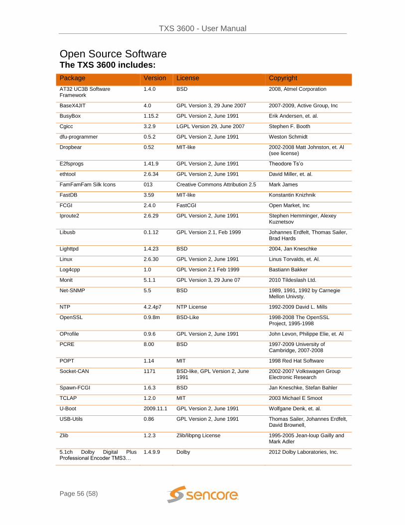
TXS 3600 - User Manual
Page 56 (58)
Open Source Software The TXS 3600 includes:
Package Version License Copyright
AT32 UC3B Software Framework
1.4.0 BSD 2008, Atmel Corporation
BaseX4JIT 4.0 GPL Version 3, 29 June 2007 2007-2009, Active Group, Inc
BusyBox 1.15.2 GPL Version 2, June 1991 Erik Andersen, et. al.
Cgicc 3.2.9 LGPL Version 29, June 2007 Stephen F. Booth
dfu-programmer 0.5.2 GPL Version 2, June 1991 Weston Schmidt
Dropbear 0.52 MIT-like 2002-2008 Matt Johnston, et. Al (see license)
E2fsprogs 1.41.9 GPL Version 2, June 1991 Theodore Ts’o
ethtool 2.6.34 GPL Version 2, June 1991 David Miller, et. al.
FamFamFam Silk Icons 013 Creative Commons Attribution 2.5 Mark James
FastDB 3.59 MIT-like Konstantin Knizhnik
FCGI 2.4.0 FastCGI Open Market, Inc
Iproute2 2.6.29 GPL Version 2, June 1991 Stephen Hemminger, Alexey Kuznetsov
Libusb 0.1.12 GPL Version 2.1, Feb 1999 Johannes Erdfelt, Thomas Sailer, Brad Hards
Lighttpd 1.4.23 BSD 2004, Jan Kneschke
Linux 2.6.30 GPL Version 2, June 1991 Linus Torvalds, et. Al.
Log4cpp 1.0 GPL Version 2.1 Feb 1999 Bastiann Bakker
Monit 5.1.1 GPL Version 3, 29 June 07 2010 Tildeslash Ltd.
Net-SNMP 5.5 BSD 1989, 1991, 1992 by Carnegie Mellon Univsty.
NTP 4.2.4p7 NTP License 1992-2009 David L. Mills
OpenSSL 0.9.8m BSD-Like 1998-2008 The OpenSSL Project, 1995-1998
OProfile 0.9.6 GPL Version 2, June 1991 John Levon, Philippe Elie, et. Al
PCRE 8.00 BSD 1997-2009 University of Cambridge, 2007-2008
POPT 1.14 MIT 1998 Red Hat Software
Socket-CAN 1171 BSD-like, GPL Version 2, June 1991
2002-2007 Volkswagen Group Electronic Research
Spawn-FCGI 1.6.3 BSD Jan Kneschke, Stefan Bahler
TCLAP 1.2.0 MIT 2003 Michael E Smoot
U-Boot 2009.11.1 GPL Version 2, June 1991 Wolfgane Denk, et. al.
USB-Utils 0.86 GPL Version 2, June 1991 Thomas Sailer, Johannes Erdfelt, David Brownell,
Zlib 1.2.3 Zlib/libpng License 1995-2005 Jean-loup Gailly and Mark Adler
5.1ch Dolby Digital Plus Professional Encoder TMS3…
1.4.9.9 Dolby 2012 Dolby Laboratories, Inc.

TXS 3600 - User Manual
Page 57 (58)
Warranty
Sencore One-Year Warranty
Sencore warrants this instrument against defects from any cause, except acts of God and abusive use, for a period of 1 (one) year from date of purchase. During this warranty period, Sencore will correct any covered defects without charge for parts, labor, or recalibration.
Support and Contact Information
Returning Products for Service or Calibration
The TXS 3600 is a delicate piece of equipment and needs to be serviced and repaired by Sencore. Periodically it is necessary to return a product for repair or calibration. In order to expedite this process please carefully read the instructions below.
RMA Number
Before any product can be returned for service or calibration, an RMA number must be obtained. In order to obtain a RMA number, use the following steps:
1. Contact the Sencore service department by going online to www.sencore.com and select Support.
2. Select Service and Repair from the options given. 3. Fill in the following required information:
a. First & Last Name b. Company c. Email d. Phone Number e. Ship and Bill to Address f. Unit Model and Serial Numbers
4. A RMA number will be emailed you shortly after completing the form with return instructions.
Shipping the Product
Once an RMA number has been issued, the unit needs to be packaged and shipped back to Sencore. It’s best to use the original box and packaging for the product but if this not available, check with the customer service representative for the proper packaging instructions.
Note: DO NOT return any power cables or accessories unless instructed to do so by the customer service representative.

Sencore Inc.
3200 Sencore Drive
Sioux Falls, SD 57107 USA
www.sencore.com
Copyright © 2014 Sencore Inc. 1.605.978.4600

![Cloud Transcoder: Bridging the Format and Resolution Gap between Internet Videos …net.pku.edu.cn/~lzh/papers/[NOSSDAV'12] Cloud Transcoder... · 2012-06-08 · Cloud Transcoder:](https://static.documents.pub/doc/80x56/5e694ca3d7372a772808bcd4/cloud-transcoder-bridging-the-format-and-resolution-gap-between-internet-videos.jpg)


