60
1ZSC000857-AAB en, Rev. 3 Type TEC, Transformer Electronic Control System Technical guide

1ZSC000857-AAB en, Rev. 3
Type TEC, Transformer Electronic Control SystemTechnical guide

This Technical Guide has been produced to provide transformer manufacturers, and their designers and engineers, access to all the technical information required to assist them in their selection of a monitoring system. It is also intended as a TEC system information source for end-users.
The information provided in this document is intended to be general and does not cover all possible applications. Any specific application not covered should be referred directly to ABB.
ABB makes no warranty or representation and assumes no liability for the accuracy of the information in this document or for the use of such information. All information in this document is subject to change without notice.
We reserve all rights to this document and the information contained herein. Reproduction, use or disclosure to third parties without express permission is strictly forbidden.
© Copyright 2008 ABB
Declaration of conformity
The manufacturer ABB AB Components SE-771 80 LUDVIKA Sweden
Hereby declares that
The product Transformer Electronic Control
by design comply with the following requirements:
• EMC Directive 89/336/EEC (amended by Directive 91/263/EEC, Directive 92/31/EEC and Directive 93/68/EEC) regarding the intrinsic characteristics to emission and immunity levels and
• LowVoltageDirective73/23/EEC(modifiedbyDirective93/68/EEC).
Date 2008-01-30
Signedby ......................................................................... Carl-Henrik Wigert
Title General Manager TEC

Recommended PracticesABB recommends careful consideration of the following factors when installing the Transformer Electronic Control:
Before you install or commission a unit, make sure that the personnel conducting the work have read and fully understood the Installation and Commissioning Guideprovidedwiththeunit.
Toavoiddamagingtheunit,neverexceedtheoperationortemperaturelimits.
DonotalterormodifyaunitwithoutfirstconsultingABB.
Followlocalandinternationalwiringregulationsatalltimes.
Useonlyfactory-authorizedreplacementpartsandprocedures.
WARNING, CAUTION, and NOTE
WARNING
A WARNING provides information which, if disregarded, could result in injury or death.
CAUTION
A CAUTION provides information which, if disregarded, could result in damage to the equipment.
NOTE: A NOTE provides additional information to assist in carrying out the work described.
TrademarksInternet Explorer® and Excel® are registered trademarks of Microsoft CorporationintheUnitedStatesandothercountries.
HYDRAN® is a registered trademark of General Electric Company in the United Statesandothercountries.
•
•
•
•
•


Table of contents1 About this manual ________________________________________________ 7
1.1 General ____________________________________________________ 71.2 Terminology ________________________________________________ 71.3 Relateddocumentation________________________________________ 7
2 Introduction _____________________________________________________ 8
3 Hardware _______________________________________________________ 93.1 TECBasic _________________________________________________ 93.1.1 Cabinet _________________________________________________ 93.1.1.1 Generalinformation ___________________________________ 113.1.1.4 Frontpanel __________________________________________ 123.1.1.5 Heater _____________________________________________ 133.1.1.6 Lights ______________________________________________ 133.1.1.7 24Vpowersupply ____________________________________ 133.1.1.8 Standardterminals ____________________________________ 143.1.1.9 CablebetweenTECandtransformercabinet _______________ 14
3.2 TECIntegrated _____________________________________________ 153.2.1 Rack __________________________________________________ 153.2.1.1 Generalinformation ___________________________________ 17
3.3 Generalhardware ___________________________________________ 183.3.1 Electronicboardsandterminals _____________________________ 183.3.2 Powersupply ___________________________________________ 183.3.2.1 PowersupplyboardTC110andterminalsX1,X2,X3 _______ 19
3.3.3 Processor ______________________________________________ 203.3.3.1 ProcessorboardTC122andterminalX11 _________________ 20
3.3.4 Analoginput4-20mA ____________________________________ 213.3.4.1 AnalogInput4-20mAboardTC130andterminalX21 _______ 21
3.3.5 TemperatureinputPt100 __________________________________ 223.3.5.1 TemperatureinputboardTC140andterminalX31 __________ 22
3.3.6 Digitalinput ____________________________________________ 233.3.6.1 DigitalinputboardTC150andterminalX41 _______________ 23
3.3.7 Controlandoutput _______________________________________ 253.3.7.1 ControlandoutputboardTC160andterminalX51 __________ 25
3.4 Accessories _______________________________________________ 273.4.1 Fiber-opticconverterTC190 ______________________________ 273.4.1.1 Timesynchronization _________________________________ 27
3.4.2 MotorrelayTC180 ______________________________________ 273.4.3 AlarmboxTC181 _______________________________________ 28
3.5 Performedtests ____________________________________________ 293.5.1 EMC(ElectroMagneticCompatibility)tests __________________ 293.5.2 Mechanicaltests,vibrationandseismic ______________________ 303.5.3 Climatetests____________________________________________ 303.5.4 Fiber-opticconverterTC190tests __________________________ 313.5.4.1 EMCtests __________________________________________ 313.5.4.2 Climatetests ________________________________________ 31
3.6 Trip,alarm,andwarningoutputfromTEC _______________________ 323.6.1 OutputsignalsfromTECcabinet ___________________________ 323.6.2 Alarm/Warningoutputoptions _____________________________ 323.6.3 Tripoutputoptions _______________________________________ 333.6.4 ConnectionofdevicesinparallelbothtraditionallyandtoTEC ___ 34
4 Software ______________________________________________________ 364.1 Transformerstatus __________________________________________ 374.1.1 Transformertopandbottomoiltemperature ___________________ 384.1.2 Currentmeasurement _____________________________________ 384.1.3 Tap-changertemperature __________________________________ 384.1.4 Tap-changerposition _____________________________________ 384.1.5 Voltagemeasurement _____________________________________ 38
4.2 Hot-spotcalculation _________________________________________ 394.3 Coolingcontrol ____________________________________________ 394.4 Ageing ___________________________________________________ 414.5 Overloadcapacity __________________________________________ 414.6 Hot-spotloadingforecasts ____________________________________ 424.7 Tap-changercontactwear ____________________________________ 434.8 Hydrogen ________________________________________________ 444.9 Moisturecontentinthetransformerandtap-changeroil _____________ 454.10 Transformertemperaturebalance ______________________________ 454.11 Tap-changertemperaturebalance ______________________________ 464.12 On-siteconfiguration ________________________________________ 464.13 Eventhandling _____________________________________________ 464.13.1 Eventlist ______________________________________________ 474.13.2 Protection ______________________________________________ 484.13.3 Sensorbackup __________________________________________ 484.13.3.1 Effectofsensorfailureonfunctions ______________________ 49
4.13.4 Messageboxes __________________________________________ 504.14 Cabinetconditions __________________________________________ 504.15 Communication ____________________________________________ 504.16 Configurableinputs _________________________________________ 514.17 Orderingdata ______________________________________________ 514.17.1 Loadtest_______________________________________________ 51
5 Installation _____________________________________________________ 525.1 Sensors ___________________________________________________ 525.1.1 Airtemperature _________________________________________ 535.1.2 Oiltemperature _________________________________________ 545.1.2.1 UseofTECbottomoilsensor ___________________________ 54
5.1.3 Currenttransducer _______________________________________ 555.1.4 Hydrogengasinoil ______________________________________ 555.1.5 Moistureinoilsensor ____________________________________ 55
5.2 Cablesandearthing _________________________________________ 565.2.1 Pt100 _________________________________________________ 565.2.2 Digitalin ______________________________________________ 565.2.3 4–20mA______________________________________________ 565.2.4 RS485anddatacommunication ____________________________ 565.2.5 CANcommunication _____________________________________ 565.2.6 CableentryandRoxtec ___________________________________ 57
5.3 Timesynchronization ________________________________________ 57
6 TECAdvancedPC ______________________________________________ 58
71ZSC000857-AAB en, Rev. 3
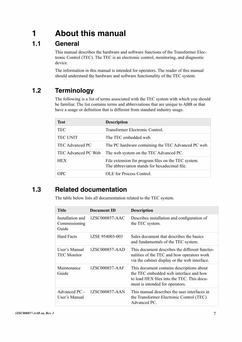
1 About this manual1.1 General
This manual describes the hardware and software functions of the Transformer Elec-tronicControl(TEC).TheTECisanelectroniccontrol,monitoring,anddiagnosticdevice.
Theinformationinthismanualisintendedforoperators.ThereaderofthismanualshouldunderstandthehardwareandsoftwarefunctionalityoftheTECsystem.
1.2 TerminologyThe following is a list of terms associated with the TEC system with which you should befamiliar.ThelistcontainstermsandabbreviationsthatareuniquetoABBorthathaveausageordefinitionthatisdifferentfromstandardindustryusage.
Test Description
TEC TransformerElectronicControl.
TEC UNIT TheTECembeddedweb.
TECAdvancedPC ThePChardwarecontainingtheTECAdvancedPCweb.
TECAdvancedPCWeb ThewebsystemontheTECAdvancedPC.
HEX FileextensionforprogramfilesontheTECsystem. Theabbreviationstandsforhexadecimalfile.
OPC OLEforProcessControl.
1.3 Related documentationThetablebelowlistsalldocumentationrelatedtotheTECsystem.
Title Document ID Description
Installation and Commissioning Guide
1ZSC000857-AAC Describesinstallationandconfigurationof theTECsystem.
Hard Facts 1ZSE954003-003 Sales document that describes the basics andfundamentalsoftheTECsystem.
User’s Manual TEC Monitor
1ZSC000857-AAD This document describes the different functio-nalities of the TEC and how operators work viathecabinetdisplayorthewebinterface.
Maintenance Guide
1ZSC000857-AAF This document contains descriptions about the TEC embedded web interface and how toloadHEXfilesintotheTEC.Thisdocu-mentisintendedforoperators.
AdvancedPC-User’s Manual
1ZSC000857-AAN This manual describes the user interfaces in the Transformer Electronic Control (TEC) AdvancedPC.

8 1ZSC000857-AAB en, Rev. 3
tec_0220
The inputs from the different sensors are connected to the input boards of the TEC unit.TheTECunitcollectsandprocessesthedata.Theunitusesdetailedmathemati-calmodelsofthetransformer,includingfingerprintdatafromtheheatruntest.Theresults can be transferred to the control system and/or viewed via a graphic web inter-faceonaPC.
Thesystemisconfiguredwhenorderingbyfillingintheorderdatasheetandisthendeliveredready-configuredaccordingtosaidspecification.
2 IntroductionEquipping a transformer with an electronic control device opens the door to any numberofnewpossibilitiescomparedwithcurrentrelaytechniques.Monitoringand diagnostics tools can be included and all transformer-related information can be gatheredinoneplaceforevaluationandstorage.Theelectroniccontroldevicewillnotonlyreplacefunctionalitythatiscurrentlymostlyachievedwithrelaytechniques–itcanaddseveralnewfeaturestoimprovetransformerperformance.
ABB’s Transformer Electronic Control (TEC) is an electronic control, monitoring, and diagnosticdevice.Thesystemisconfiguredusinga“fingerprint”ofthetransformer.The device provides a single interface to the entire transformer with current and historicalstatusdataandthepotentialtopredictloads.Aminimumnumberofextrasensorsisneeded.

91ZSC000857-AAB en, Rev. 3
3 HardwareThere are two versions of the TEC unit:
TEC Basic
TECIntegrated.
ThebasicmodelismountedinaTECcabinetwithitsownterminalgroups.
The integrated model is based on the same concept as TEC Basic, but without the TEC cabinet.Itislocatedonarackthatcanbemountedinsidethetransformercabinet.
3.1 TEC BasicTheTECBasicmodelismountedinaTECcabinetwithitsownterminalgroups.
3.1.1 Cabinet
•
•
Display
Cabinet door
Extra roof
Displaybutton
Lock handle
Cable entry
Status lights
tec_0114

10 1ZSC000857-AAB en, Rev. 3
tec_0019
For cable Ø 9.5 - 32.5 mm (5x)
Cable sealing (option)
For cable Ø 4 - 16.5 mm
Connection to transformer control cabinet
Fiber-optic cable
342
Standard cable entrance plate
Earthing terminal M12
Ø 9 1)
178
176
159
66 40
278
256
510
78
601
526
500 300
340
3764
8
600
462
1) Mounting holes on the transformer.
M10 x 25
9611
4

111ZSC000857-AAB en, Rev. 3
3.1.1.1 General information
Environment
Operatingtemperature...............-40to+55°C(-40to131°F)
Degree of protection..................IP54,accordingtoIEC60529
Temperature cycling tested........-40to+70°C,90%humidityaccordingto IEC 60068-1, IEC 60068-2, IEC 60068-3, and IEC60068-5
Dimensions (mm)......................Width600,Height650,Depth340
Weight.......................................35kg
EMC compliance.......................IEC61000-4,EN61000-6-2andEN61000-4
Vibration tested.........................IEC60255-21-1,IEC60255-2,IEC60255-3and IEC 60068-2-6, IEC 60068-27, IEC 60068-29
Temperature cycling..................IEC 60068-2
Max.cableareatoterminals.....2.5mm²
Max.cableareatotemperatureinputPt100................................1.5mm²Color..........................................RAL7035
Input parameters
The cabinet for the TEC Basic model has the following input parameters:
8insulatedanalog4-20mAinputsviaterminals (forcurrenttransformers,sensors,etc.)
4insulatedPt100directinputs(fortemperaturesensors)
12 insulated digital input via terminals (forfanmotorstatus,alarm/tripsignals,etc.)
1 input for the tap-changer position, resistor bridge Rtot ≥ 80 W.
Thenumberofinputsignalscanbeincreased.
Output parameters
The cabinet for the TEC Basic model has the following output parameters:
3 outputs for alarm, warning, and trip signals
Permittedloadbreakingcapacityonoutputterminalsare AC250V8A,DC250V0.1AL/R=40ms,DC30V5A.
•
•
•
•
•
•

12 1ZSC000857-AAB en, Rev. 3
3.1.1.4 Front panel
Status light (inside the cabinet)
Red light indicates Alarm or Trip condition
Yellow light indicates Warning condition
GreenlightindicatesNormalconditions.
•
•
•
tec_0045
Display (on cabinet)
The display shows different information values when the button on the front of the cabinetispressed.
TheinformationonthedisplayiseasilyconfiguredfromaPCtoshowotheravailableinformation.ItisalsopossibletopresentinformationinthedisplayaboutthereasonbehindaWarningoranAlarm.ThetemperaturesaredisplayedinbothdegreesCelciusanddegreesFahrenheit.
TheTC170displayboardisconnectedtotheprocessorboardondelivery.
24 V power supply
Cable entry
Space for extra terminals
Display
Electronic boards
Standard terminals
Extra roof
Lights (x 2)
Space for extra boards
Heater
Status lights
Front panel

131ZSC000857-AAB en, Rev. 3
Information that can be shown on the display:A TOP OILB1 HOT-SPOT HVB2 HOT-SPOT LVB3 HOT-SPOT TVC BOTTOM OILD LOAD I/Irat
E OLTCPOSITIONF OLTCTEMP1F OLTCTEMP2F OLTCTEMP3F OLTCTEMP4G HYDROGENH2TFOMoistureOLTCMoisture
VoltageE1: Extra 1E2: Extra 2E3: Extra 3E4: Extra 4E5: Extra 5E6: Extra 6E7: Extra 7E8: Extra 8E9: Extra 9E10: Extra 10IP Address
Information in italics relates to optional sensors and is displayed whenavailable.
3.1.1.5 Heater
ThecabinetheaterisconnectedtotheTEC’sACsupply.ItisdesignedforanACsup-plyof100-240V.Dependingonthetemperatureinthecabinet,theheatercanprovide100-135W.(At-30°Ctheheatingpoweris135W.)
3.1.1.6 Lights
Theilluminationinthecabinetconsistoftwolightsbelowthefrontpanel.ThelightsarestandardautomotivelightbulbsoftypeBa15s18x35,24V,10W.
3.1.1.7 24 V power supply
The24Vpowersupplyisonlyintendedtosupplythelights.
tec_0057
tec_0233

14 1ZSC000857-AAB en, Rev. 3
3.1.1.9 Cable between TEC and transformer cabinet
The cable can be used for an easy connection between the transformer cabinet and the TECunit.Thecableconsistsof:
OneshieldedtwistedpaircablemarkedA.ThecableisintendedforRS485 communicationconnectiontothemotorandalarmboxes.Notethatonlytwo ofthewiresareconnected.
Twoshieldedcableswithtwotwistedpairseach.
24singleconductors.
•
•
•
tec_0046
24V power supply
Data com-munication
Analog input Digital input Control and output
Connection to transformer control cabinet. Hole PG29 (D = 38 mm)
3.1.1.8 Standard terminals
tec_0047
Connection to TEC cabinet
X1X2
X3 X11 X21 X41 X51

151ZSC000857-AAB en, Rev. 3
3.2 TEC IntegratedThe TEC Integrated model is located on a rack and is based on the same concept as TECBasic,butwithouttheTECcabinetandtheheater.
3.2.1 RackThe advantage of the Integrated version is that it can be mounted inside the transform-ercabinet.TheIntegratedmodelhasadisplaywiththesamefunctionalityastheBasicmodeldisplay.Formoreinformationaboutthedisplay,seesection3.1.1.4.
Display
Space for extra boards
Displaybutton
Status lights
24 V power supply
Space for extra terminals
Standard terminals
tec_0249

16 1ZSC000857-AAB en, Rev. 3
tec_0250
131
72430
149
12
526
8
Min 275
420
450
171ZSC000857-AAB en, Rev. 3
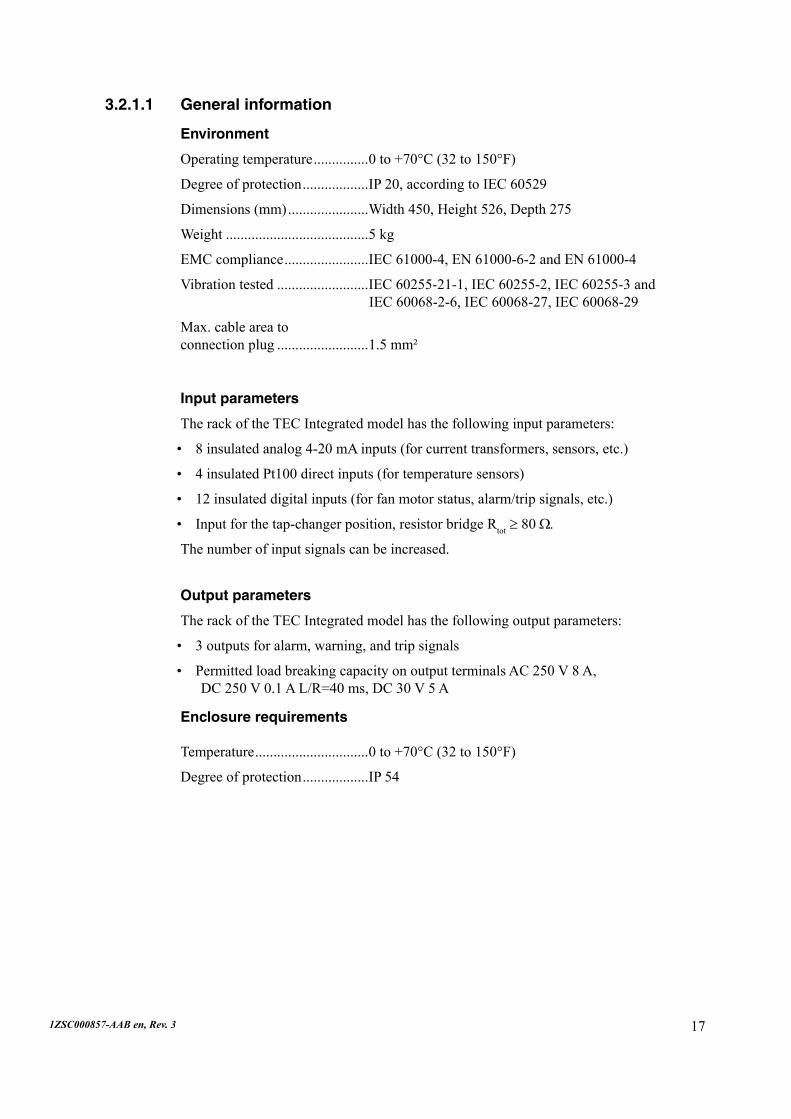
3.2.1.1 General information
Environment
Operatingtemperature...............0to+70°C(32to150°F)
Degree of protection..................IP20,accordingtoIEC60529
Dimensions (mm)......................Width450,Height526,Depth275
Weight.......................................5kg
EMC compliance.......................IEC61000-4,EN61000-6-2andEN61000-4
Vibration tested.........................IEC60255-21-1,IEC60255-2,IEC60255-3and IEC 60068-2-6, IEC 60068-27, IEC 60068-29
Max.cableareatoconnection plug.........................1.5mm²
Input parameters
The rack of the TEC Integrated model has the following input parameters:
8insulatedanalog4-20mAinputs(forcurrenttransformers,sensors,etc.)
4insulatedPt100directinputs(fortemperaturesensors)
12insulateddigitalinputs(forfanmotorstatus,alarm/tripsignals,etc.)
Input for the tap-changer position, resistor bridge Rtot ≥ 80 W.
Thenumberofinputsignalscanbeincreased.
Output parameters
The rack of the TEC Integrated model has the following output parameters:
3 outputs for alarm, warning, and trip signals
PermittedloadbreakingcapacityonoutputterminalsAC250V8A, DC250V0.1AL/R=40ms,DC30V5A
Enclosure requirements
Temperature...............................0to+70°C(32to150°F)
Degree of protection..................IP54
•
•
•
•
•
•
18 1ZSC000857-AAB en, Rev. 3
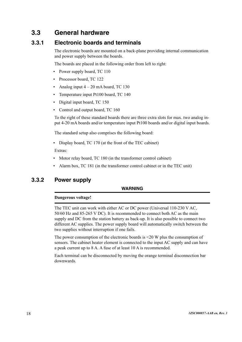
3.3 General hardware
3.3.1 Electronic boards and terminalsThe electronic boards are mounted on a back-plane providing internal communication andpowersupplybetweentheboards.
The boards are placed in the following order from left to right:
Powersupplyboard,TC110
Processorboard,TC122
Analoginput4–20mAboard,TC130
TemperatureinputPt100board,TC140
Digitalinputboard,TC150
Control and output board, TC 160
Totherightofthesestandardboardstherearethreeextraslotsformax.twoanalogin-put4-20mAboardsand/ortemperatureinputPt100boardsand/ordigitalinputboards.
The standard setup also comprises the following board:
Display board, TC 170 (at the front of the TEC cabinet)
Extras:
Motor relay board, TC 180 (in the transformer control cabinet)
Alarm box, TC 181 (in the transformer control cabinet or in the TEC unit)
3.3.2 Power supplyWARNING
Dangerous voltage!
The TEC unit can work with either AC or DC power (Universal 110-230 V AC, 50/60Hzand85-265VDC).ItisrecommendedtoconnectbothACasthemainsupplyandDCfromthestationbatteryasback-up.ItisalsopossibletoconnecttwodifferentACsupplies.Thepowersupplyboardwillautomaticallyswitchbetweenthetwosupplieswithoutinterruptionifonefails.
The power consumption of the electronic boards is <20 W plus the consumption of sensors.ThecabinetheaterelementisconnectedtotheinputACsupplyandcanhaveapeakcurrentupto8A.Afuseofatleast10Aisrecommended.
Each terminal can be disconnected by moving the orange terminal disconnection bar downwards.
•
•
•
•
•
•
•
•
•

191ZSC000857-AAB en, Rev. 3
Terminal group X1
1 Input85-264VAC50/60Hzlinevoltage.
2,3 OutputAClinevoltage.ConnectedtoX1:1andisalways live, even if the terminal disconnectionbarismovedtothedisconnectedposition.Thisterminalcanbeusedtosupplyspecialsensorswithpower.
4 InputACneutral.
5,6 OutputACneutral.
Terminal group X2
1 Input85-264VDCpositive.
2 Input85-264VDCnegative.
Terminal group X3
1 Output24VDCpositivefromthepowersupplyboard.Thedisplay(1.6W)is internallywiredtothissupply.Upto3currenttransducerscanalsobeconnec-tedhere.Maximumtotalloadonthissupplyis5W.
2 Output24VDCnegativefromthepowersupplyboard. Upto3currenttransducerscanalsobeconnectedhere.
3 Input24VDCpositivefromaseparate24VsupplyunitintheTECcabinet(connectedondelivery).Thispowerfeedsthecabinetlight.
4 Output24VDCpositivefromX3:3.Thisterminalisusedtopower4-20mAsensors(exceptforcurrenttransformers,CTs).
5 Input24VDCnegative.
6 Output24VDCnegativefromX3:5.
tec_0048
85 - 264 V AC (or DC) input via terminal group X1
85 - 264 V DC (or AC) input via terminal group X2
24 V DC output via terminal group X3 to TEC display and current transducers
123
456
789
3.3.2.1 Power supply board TC 110 and terminals X1, X2, X3
tec_0049X1 X2
X3

20 1ZSC000857-AAB en, Rev. 3
3.3.3 Processor
tec_0217 tec_0050
LEDs: green and red
RS 232 DIN connection for system administration (loading new code)
Fiber-optic input, ST connector from TC 190 (optional)
Fiber-optic output, ST connector to TC 190 (optional)
RS 485 connection to display board and motor relay board via terminal group X11
123456
Earth
Terminal group X11
1 CAN bus, High
2 CAN bus, Low
3 CAN bus, CAN signal ground
4 CANbus,protectiveearth
5 RS485connectionAtomotorrelayboard
6 RS485connectionBtomotorrelayboard
3.3.3.1 Processor board TC 122 and terminal X11
X11
211ZSC000857-AAB en, Rev. 3
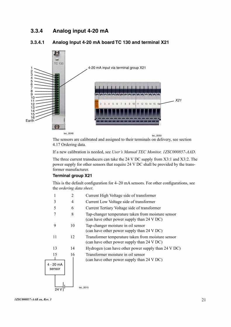
3.3.4 Analog input 4-20 mA
The sensors are calibrated and assigned to their terminals on delivery, see section 4.17Orderingdata.
If a new calibration is needed, see User’s Manual TEC Monitor, 1ZSC000857-AAD.
Thethreecurrenttransducerscantakethe24VDCsupplyfromX3:1andX3:2.Thepowersupplyforothersensorsthatrequire24VDCshallbeprovidedbythetrans-formermanufacturer.Terminal group X21
Thisisthedefaultconfigurationfor4–20mAsensors.Forotherconfigurations,see the ordering data sheet.
1 2 Current High Voltage side of transformer3 4 CurrentLowVoltagesideoftransformer5 6 CurrentTertiaryVoltagesideoftransformer 7 8 Tap-changer temperature taken from moisture sensor (canhaveotherpowersupplythan24VDC) 9 10 Tap-changer moisture in oil sensor (canhaveotherpowersupplythan24VDC) 11 12 Transformer temperature taken from moisture sensor (canhaveotherpowersupplythan24VDC)13 14 Hydrogen(canhaveotherpowersupplythan24VDC)15 16 Transformermoistureinoilsensor (canhaveotherpowersupplythan24VDC)
tec_0048tec_0050
4-20 mA input via terminal group X2112345678910111213141516
Earth
24 V
4 - 20 mA sensor
tec_0015
X21
3.3.4.1 Analog Input 4-20 mA board TC 130 and terminal X21
22 1ZSC000857-AAB en, Rev. 3
Position X31
1234567891011121314151617
AdditionalTC130boardsusethesameprinciple.
Current transducer
The current transducer is connected to the TEC unit as follows:
Connect+24VfromX3:1to“plus”sideofsensor.
Connect“minus”sideofsensortoTECterminal(lowterminalnumber1,3and5).
Connect0VfromX3:2toTECterminal(highterminalnumber2,4and6).
1.
2.
3.
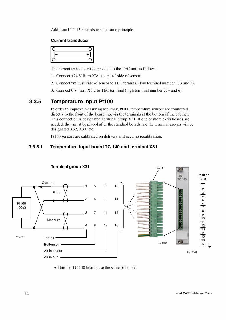
3.3.5 Temperature input Pt100Inordertoimprovemeasuringaccuracy,Pt100temperaturesensorsareconnecteddirectlytothefrontoftheboard,notviatheterminalsatthebottomofthecabinet.ThisconnectionisdesignatedTerminalgroupX31.Ifoneormoreextraboardsareneeded, they must be placed after the standard boards and the terminal groups will be designatedX32,X33,etc.
Pt100sensorsarecalibratedondeliveryandneednorecalibration.
Pt100 100 W
Current
Feed
Measure
Top oil
Bottom oil
Air in shade
Air in sun
tec_0016
tec_0048
tec_0051
Terminal group X31
AdditionalTC140boardsusethesameprinciple.
1 5 9 13
2 6 10 14
3 7 11 15
4 8 12 16
3.3.5.1 Temperature input board TC 140 and terminal X31
X31
231ZSC000857-AAB en, Rev. 3
1 2 8 17 17 18
tec_0048 tec_0046
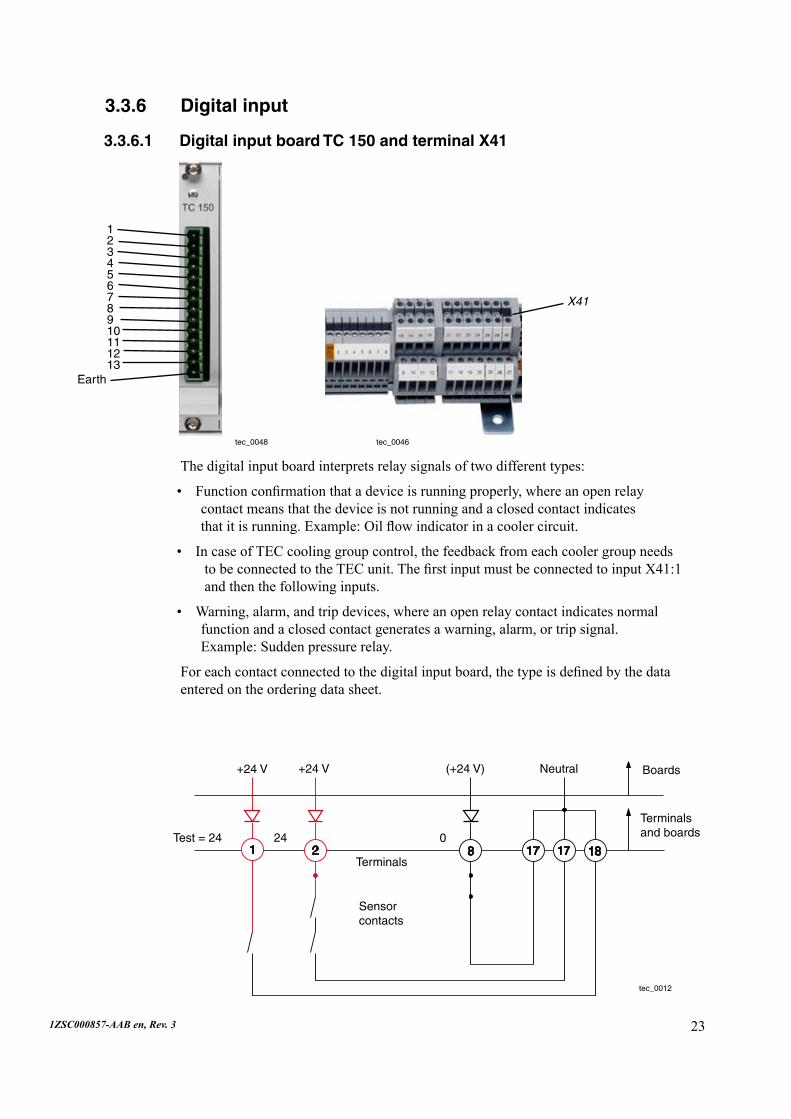
The digital input board interprets relay signals of two different types:
Functionconfirmationthatadeviceisrunningproperly,whereanopenrelay contact means that the device is not running and a closed contact indicates thatitisrunning.Example:Oilflowindicatorinacoolercircuit.
In case of TEC cooling group control, the feedback from each cooler group needs tobeconnectedtotheTECunit.ThefirstinputmustbeconnectedtoinputX41:1 andthenthefollowinginputs.
Warning, alarm, and trip devices, where an open relay contact indicates normal functionandaclosedcontactgeneratesawarning,alarm,ortripsignal. Example:Suddenpressurerelay.
Foreachcontactconnectedtothedigitalinputboard,thetypeisdefinedbythedataenteredontheorderingdatasheet.
•
•
•
3.3.6 Digital input
12345678910111213
Earth
+24 V +24 V (+24 V) Neutral
Test = 24 24 0
Terminals
Sensor contacts
Terminals and boards
tec_0012
Boards
3.3.6.1 Digital input board TC 150 and terminal X41
X41
24 1ZSC000857-AAB en, Rev. 3
9 12 23 24 29 26 9 12 23 24 29 26
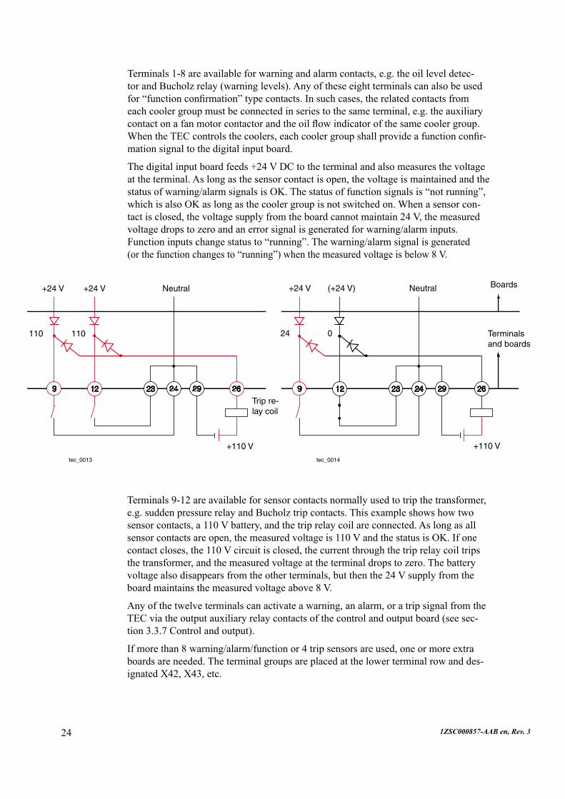
Terminals 9-12 are available for sensor contacts normally used to trip the transformer, e.g.suddenpressurerelayandBucholztripcontacts.Thisexampleshowshowtwosensorcontacts,a110Vbattery,andthetriprelaycoilareconnected.Aslongasallsensorcontactsareopen,themeasuredvoltageis110VandthestatusisOK.Ifonecontact closes, the 110 V circuit is closed, the current through the trip relay coil trips thetransformer,andthemeasuredvoltageattheterminaldropstozero.Thebatteryvoltagealsodisappearsfromtheotherterminals,butthenthe24Vsupplyfromtheboardmaintainsthemeasuredvoltageabove8V.
Any of the twelve terminals can activate a warning, an alarm, or a trip signal from the TEC via the output auxiliary relay contacts of the control and output board (see sec-tion3.3.7Controlandoutput).
Ifmorethan8warning/alarm/functionor4tripsensorsareused,oneormoreextraboardsareneeded.Theterminalgroupsareplacedatthelowerterminalrowanddes-ignatedX42,X43,etc.
Terminals1-8areavailableforwarningandalarmcontacts,e.g.theoilleveldetec-torandBucholzrelay(warninglevels).Anyoftheseeightterminalscanalsobeusedfor“functionconfirmation”typecontacts.Insuchcases,therelatedcontactsfromeachcoolergroupmustbeconnectedinseriestothesameterminal,e.g.theauxiliarycontactonafanmotorcontactorandtheoilflowindicatorofthesamecoolergroup.WhentheTECcontrolsthecoolers,eachcoolergroupshallprovideafunctionconfir-mationsignaltothedigitalinputboard.
Thedigitalinputboardfeeds+24VDCtotheterminalandalsomeasuresthevoltageattheterminal.Aslongasthesensorcontactisopen,thevoltageismaintainedandthestatusofwarning/alarmsignalsisOK.Thestatusoffunctionsignalsis“notrunning”,whichisalsoOKaslongasthecoolergroupisnotswitchedon.Whenasensorcon-tactisclosed,thevoltagesupplyfromtheboardcannotmaintain24V,themeasuredvoltagedropstozeroandanerrorsignalisgeneratedforwarning/alarminputs. Functioninputschangestatusto“running”.Thewarning/alarmsignalisgenerated (orthefunctionchangesto“running”)whenthemeasuredvoltageisbelow8V.
tec_0013
+24 V +24 V Neutral
110 110
+110 V
tec_0014
Trip re-lay coil
+24 V (+24 V) Neutral
24 0 Terminals and boards
Boards
+110 V

251ZSC000857-AAB en, Rev. 3
3.3.7 Control and output
Terminal group X41
Each sensor is connected to one of the terminals 1-12 and one of the neutral terminals17-24.1-8 Inputwarning/alarmandfunctionsensorcontacts.
9-12 Inputtripsensorcontacts.
13-16 Shallnotbeused.
17-24 Inputneutral.Eachterminalnumberrepresentstwoterminals, oneontheuppersideandoneonthelowerside.
25 Shallnotbeused.
26 Input positive DC from battery and trip relay coil according todiagramabove.Voltagesabove+220VDCandnegative voltagesarenotpermitted.
27-28 Shallnotbeused.
29 Inputneutralfrombatteryandtriprelaycoil.
30 Shallnotbeused.
Seesection3.6fortripandalarm/warningfunctionality.
tec_0218tec_0046
1234567891011121314
Earth
3.3.7.1 Control and output board TC 160 and terminal X51
X51

26 1ZSC000857-AAB en, Rev. 3
Thisboardisusedtocreaterelaysignals.
WARNING
Dangerous voltage!
Terminal group X51
1 Outputdisconnectableterminalinserieswithterminal14(Disconnectedindownwardsposition.)
2-3 Inputvoltagemeasurements.Nominalvoltage85–140VAC.Neutralon3.
4-6 Inputtap-changerpositiontransmitter, 4=max.position,5=movingcontact, 6=min.position.Rtot≥80Ω. 0Ωinpos1.
7-9 Configurableoutputdrycontact.
10,12 Outputdrycontactforwarning.
11,12 Outputdrycontactforalarm.
13,14 Outputdrycontactfortrip. This output also has a contact that canbedisconnectedatterminal1. These contacts are wired to the digital boardtocreateatripoutputonX41:26 andX41:29.
Permitted load
Permittedload(breakingcapacity)onoutputterminals:AC 250V 8ADC 250V 0.1A L/R=40msDC 30V 5A
14
789
101112
13
tec_0017

271ZSC000857-AAB en, Rev. 3
3.4 Accessories
3.4.1 Fiber-optic converter TC 190For remote data communication, including withinthestationbuilding,afiber-opticcon-nectionshouldbeused.
Thefiber-opticcableshouldbeconnectedtotheTC190converter.TheTC190convertershould be placed indoors and requires a separate24VDCpowersupply.
3.4.1.1 Time synchronization
Theinputsignalforthetimesynchronizationshouldbe5Vwith50W output im-pedance.TheconnectionisaBNCcontactanditisrecommendedtouseashieldedcoaxialcable.Thepulseshouldhavepositiveflankforindication.
3.4.2 Motor relay TC 180TheTC180motorrelayboardisplacedinthetransformercontrolcabinet.
tec_0053
tec_0054
tec_0055
+24 V
0
RS 485 A
RS 485 B
Power
1
2
3
4
5
6
Cooler group
LEDs
tec_0215
All fans and pumps in a single cooler group must be connected so that they are started byonerelayoutput.Uptosixseparategroupscanbecontrolled.TheshieldedcableA in the cable between the TEC and the transformer cabinet is intended for the RS 485communication.IftheRS485connectiontotheTECislost,allrelayswillcloseautomaticallyonebyoneat10-secondintervals.AclosedrelayisrepresentedbyalitLED.Itisrecommendedthatthemotorrelayboardbesuppliedwith24VDCfromthe transformer cabinet to ensure that all motors start even if the connection to TEC failstotally.IfthepowersupplytotheTECunitisdisconnected,themotorrelayboardstartsallcoolergroups.Toavoidthiswhenthetransformerisoutofservice,first
28 1ZSC000857-AAB en, Rev. 3
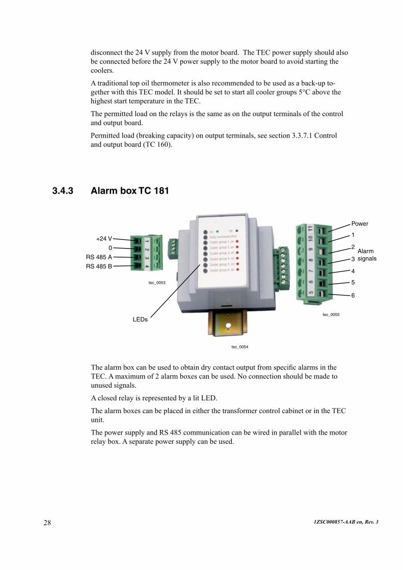
3.4.3 Alarm box TC 181
ThealarmboxcanbeusedtoobtaindrycontactoutputfromspecificalarmsintheTEC.Amaximumof2alarmboxescanbeused.Noconnectionshouldbemadetounusedsignals.
AclosedrelayisrepresentedbyalitLED.
The alarm boxes can be placed in either the transformer control cabinet or in the TEC unit.
ThepowersupplyandRS485communicationcanbewiredinparallelwiththemotorrelaybox.Aseparatepowersupplycanbeused.
tec_0053
tec_0054
tec_0055
+24 V
0
RS 485 A
RS 485 B
Power
1
2
3
4
5
6
Alarm signals
LEDs
disconnectthe24Vsupplyfromthemotorboard.TheTECpowersupplyshouldalsobeconnectedbeforethe24Vpowersupplytothemotorboardtoavoidstartingthecoolers.
A traditional top oil thermometer is also recommended to be used as a back-up to-getherwiththisTECmodel.Itshouldbesettostartallcoolergroups5°CabovethehigheststarttemperatureintheTEC.
The permitted load on the relays is the same as on the output terminals of the control andoutputboard.
Permittedload(breakingcapacity)onoutputterminals,seesection3.3.7.1Control andoutputboard(TC160).

291ZSC000857-AAB en, Rev. 3
2.5 Performed tests2.5.1 EMC (Electro Magnetic Compatibility) tests
Immunity according to EN 61000-6-2:1999Radiated RF field IEC/EN61000-4-3(1995),ENV50204(1995)Conducted RF voltage IEC/EN61000-4-6(1996)Fast transient/burst IEC/EN61000-4-4(1995)Electrostatic discharge (ESD) IEC/EN61000-4-2(1995/96)Surge IEC/EN61000-4-5(1995)LF magnetic field1 IEC/EN61000-4-8(1993)
Additional immunity testsDamped Oscillatory Wave1 IEC/EN61000-4-12(1995),SS4361503Spark1 SS4361503Power voltage variations1 IECSC77AWG6(info.Annex)
Emission according to EN 50081-2:1993Radiated emission CISPR11(1997),EN55011(1998)Conducted emission CISPR11(1997),EN55011(1998)
1) Thismethodisnotwithinthescopeofthelaboratoryaccreditation.
Emission Port Class Limits Result1
Radiated emission
Enclosure A limitsofEN55011increasedby10dBfor10m measured distance in accordance with EN 50081-2
Passed
Conducted emission
AC mains A limitsofEN55011 Passed
Immunity Immunity port
Process I/O ports
Mains port Earth ports
Result/ Criteria1
RadiatedRFfields 15V/m - - - Passed/A
Conducted RF voltage
- 10 V 10 V 10 V Passed/A
Electrostatic discharge
8 kV contact 15kVair
4kV 4kV 4kV Passed/A
Surge pulse - 4kV(CM) 4kV(CM) 2 kV (NN)
- Passed/A
Powerfrequencymagneticfield
1000 A/m - - - Passed/A
Powervoltagevariations
- - -/+10%,15s - Passed/A
Damped oscilla-tory wave
- 2.5kV 2.5kV - Passed/A
Fast transient/spark
- 4kV-8kV 4kV-8kV - Passed/A
1) Passed=Compliedwiththespecification. Failed=Didnotcomplywiththespecification.Seerelevantchapterfordetails. Criteria,seechapter4.4Criteriaforapproval.

30 1ZSC000857-AAB en, Rev. 3
2.5.2 Mechanical tests, vibration and seismicThe TEC unit manufactured by ABB in Sweden has been subjected to mechanical testingasspecifiedinchapter3.
The results of this testing are presented below:
Test Specifications Severity ResultVibration IEC60255-21-1 10-150Hz,2g,20sweepcycles OK
IEC 60068-2-6Bump IEC60255-21-2 10g, 16 ms, 6 x 1,000 bumps OK
IEC 60068-2-29Shock IEC60255-21-2 15g,11ms,6x3shocks OK
IEC 60068-2-27Seismic IEC60255-21-3 1-35Hz,7.5mm/2g,1sweep OK
IEC 60068-2-6OK:Nomalfunctionswereobservedduringthetestandnodamagewasobservedafterthetest.
2.5.3 Climate tests
Test Severity Duration StandardDry heat Operational +85°C 72 hours IEC 60068-2-2, Test BdCold Operational -40°C 72 hours IEC 60068-2-1, Test AbChange of temperature
Operational -40to+70°C 3 cycles t=2h 3°C/min
IEC60068-2-14,TestNb
Damp heat steady state
Operational +40°C,>93% non-condensing
4days IEC 60068-2-3, Test Ca
Damp heat cyclic
Operational +25to+55°C, >93%condensing
6x24-hourcycles
IEC 60068-2-30, Test Dd
311ZSC000857-AAB en, Rev. 3
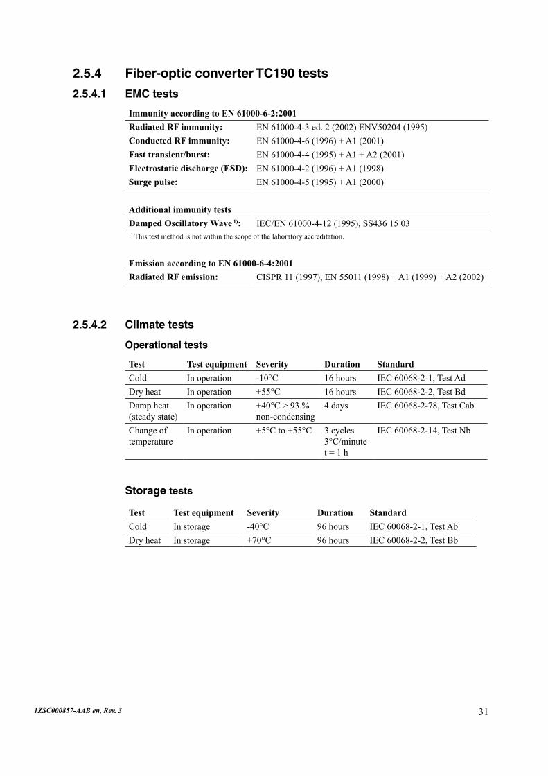
2.5.4 Fiber-optic converter TC190 tests
2.5.4.1 EMC tests
Immunity according to EN 61000-6-2:2001Radiated RF immunity: EN61000-4-3ed.2(2002)ENV50204(1995)Conducted RF immunity: EN61000-4-6(1996)+A1(2001)Fast transient/burst: EN61000-4-4(1995)+A1+A2(2001)Electrostatic discharge (ESD): EN61000-4-2(1996)+A1(1998)Surge pulse: EN61000-4-5(1995)+A1(2000)
Additional immunity testsDamped Oscillatory Wave 1): IEC/EN61000-4-12(1995),SS43615031)Thistestmethodisnotwithinthescopeofthelaboratoryaccreditation.
Emission according to EN 61000-6-4:2001Radiated RF emission: CISPR11(1997),EN55011(1998)+A1(1999)+A2(2002)
2.5.4.2 Climate tests
Operational tests
Test Test equipment Severity Duration StandardCold In operation -10°C 16 hours IEC 60068-2-1, Test AdDry heat In operation +55°C 16 hours IEC 60068-2-2, Test BdDamp heat (steady state)
In operation +40°C>93%non-condensing
4days IEC 60068-2-78, Test Cab
Change of temperature
In operation +5°Cto+55°C 3 cycles 3°C/minute t=1h
IEC60068-2-14,TestNb
Storage tests
Test Test equipment Severity Duration StandardCold In storage -40°C 96 hours IEC 60068-2-1, Test AbDry heat In storage +70°C 96 hours IEC 60068-2-2, Test Bb

32 1ZSC000857-AAB en, Rev. 3
3.6 Trip, alarm, and warning output from TEC
3.6.1 Output signals from TEC cabinetNOTE: Terminal numbers for TEC Basic only.
3.6.2 Alarm/Warning output options
Alarm/Warning option 1
ThedevicesconnectedtotheTECwillprovideanalarmsignalfromX51:11and X51:12andawarningsignalfromX51:10andX51:12.AlarmsandwarningsfromTECfunctionswillalsobeconnectedtothesecontacts.TheoptionalTC190providesthepotentialtosend,viafiber-opticcable,detailsaboutthealarmandwarningsignalsfromthedevicesandtheTECeventlogtoaPC.
Fiber-optic communication interface
anan

331ZSC000857-AAB en, Rev. 3
Alarm/Warning option 2
NodevicesconnectedtoTEC.AlarmsandwarningsfromTECfunctionswillhave thealarmsignalfromX51:11andX51:12andthewarningsignalfromX51:10andX51:12.TheoptionalTC190providesthepotentialtosend,viafiber-opticcable,detailsaboutthealarmandwarningsignalsfromtheTECeventlogtoaPC.
3.6.3 Trip output options
Trip option 1
NotripdevicesconnectedtoTEC.TripsignalsfromTECfunctionsuseX41:26andX41:29.Thecustomerconnectsthissignalthesameasanyotherdevice.Theoptional TC190providesthepotentialtosend,viafiber-opticcable,detailsaboutthetripsintheTECeventlogtoaPC.
Trip option 2
NotripdevicesconnectedtoTEC.TripfromTECfunctionsnotused.NoinformationaboutthetripsinTECeventlog.
an

34 1ZSC000857-AAB en, Rev. 3
Trip option 3
TripdevicesconnectedtotheTECwillprovideatripsignalonX41:26andX41:29. IftheTECtripisdisconnectedfromterminalX51:1,thissignalwillnotbeintegratedinthetripsumsignal.TheoptionalTC190providesthepotentialtosend,viafiber-op-tic cable, details about the trip signals from the devices and the TEC event log to aPC.
Trip option 4
Trip devices connected to the TEC and the internal TEC provide one trip signal on X41:26and29.TheoptionalTC190providesthepotentialtosend,viathefiber- optic cable, details about the trip signals from the devices and the TEC event log to aPC.
3.6.4 Connection of devices in parallel both traditionally and to TEC
Alarm/Warning devices
Thefigurebelowshowshowalarm/warningdevicescanbeconnectedthetradition-alwayinparallelwiththeTEC.Ifthevoltageinthestationalarm/warningcircuitis>24V,nodiodeisneededinthetraditionalalarm/warningcircuit.
ss

351ZSC000857-AAB en, Rev. 3
Trip devices
Thefigurebelowshowshowwarning/alarmdevicescanbeconnectedthetraditionalwayinparallelwiththeTEC.Notethatadiodeisneededinthetraditionaltripcircuit.
36 1ZSC000857-AAB en, Rev. 3
4 SoftwareThe following functionality is available in TEC and is described in this chapter:
Transformer status
Winding hot-spot temperature calculation
Cooling control
Thermal ageing
Overloadcapacity
Loading forecast
Tap-changer contact wear
Hydrogen
Moisture in transformer and tap-changer
Transformer temperature balance
Tap-changer temperature balance
On-siteconfiguration
Event handling
Communication
Configurableinputs.
•
•
•
•
•
•
•
•
•
•
•
•
•
•
•

371ZSC000857-AAB en, Rev. 3
4.1 Transformer statusThe display and the main page of the web interface show the present status of the transformer.Theyshowboththevaluesofsomeimportantparametersandtheoverallstatus,symbolizedbyasmallflashingWarning,Alarm,orTripindicator.Thetrans-formerhistorycanalsobedisplayedinthewebinterface.
Thebasicsystemvaluesdisplayedaredescribedbelow.
Thewebinterfaceshowthestatusofthetransformer.
Thescreenbelowshowsthecurrentstatusofthetransformer.
Historicaldatacanbedisplayedincharts.
Smallflashingindicatorsigns(oneforeachevent)appeartotheleft/right oftheaffectedvaluefieldaswellasonthequicktabs).
The language used on all TEC screens can be switched between the two pre-configuredlanguages(NativeandEnglish).
ConnectiontotheTECispossiblefromaPCwithInternetExplorer®. -TheTECcaneasilybeconnectedtoaLAN.
-TheTECcanbeconnectedtoamodemforaccessoverthephone.
•
•
•
•
•
tec_0234

38 1ZSC000857-AAB en, Rev. 3
tec_0235
4.1.1 Transformer top and bottom oil temperatureThetransformertopandbottomoiltemperatureismeasuredanddisplayed.
4.1.2 Current measurementThe currents from the transformer CTs are used to calculate the current in the wind-ingsandbushings.Itisthebushingcurrentthatisdisplayedintheinterface.Thehighestloadisusedtoindicatetheloadofthetransformer.Theaccuracyofthecurrentmeasurementisapproximately3%offullload.
4.1.3 Tap-changer temperatureThetemperatureinthetap-changersismeasured.Thehistoricalmeasuredtemperaturecan easily be compared with the transformer and outdoor temperatures in the web interfacetocheckthatthesituationisstable.Thesamechartcanalsodisplaytheload.Somerolesarealsodescribedinthechapteraboutoperations.
4.1.4 Tap-changer positionThisfunctionkeepstrackofthetap-changerposition.
4.1.5 Voltage measurementThevoltageinthetransformercanbeconnectedtotheTECunit.The85-145Vsignalmustcomefromanexternaldevice.

391ZSC000857-AAB en, Rev. 3
4.2 Hot-spot calculationThewindinghot-spotiscalculatedtofulfillbothIECorIEEE.
ForOF(oilforced)andOD(oildirected)transformersthehot-spotiscalculated fromthebottomoiltemperature.Thisprovidesamoreaccuratecalculationof thehot-spotcomparedwithcalculationsbasedonthetopoiltemperature.
Thehot-spotcalculationcanbemadeforupto3windings.Thehot-spotcalcu- lations are made without the normal time delay (≈ 6 min) to enable quicker coolinginitiation.
ThevalueswillbeshownonthedisplayandinTECMonitor.Historicalvalues canalsobedisplayedinTECMonitor.
4.3 Cooling controlThecoolingcontrolcanbeusedforbothcoolerandradiatorcooledtransformers.Enhancements over traditional cooling are:
TECcancontrolupto6coolergroups.
Startsontopoil,hot-spot,andforecast.
Allcoolergroupsusedthroughpermutation.
Allcoolergroupsarestartedeveryweek.
Timeinserviceshowninthestationinterface.
Timedelaybetweenmotorstart.
Fail-safeoperation.
1. TEC can control up to 6 cooler groups
This makes it possible to run the cooling in up to six steps instead of the normal two steps.Thiswill:
Reducethenoiselevel.
Keepthetransformertemperatureatamorestablelevelandreducebreathing.
Saveenergyasonlythenecessaryamountofcoolingisactivated.
2. Starts on top oil, hot-spot, and forecast
The cooling will be controlled by:
Topoiltemperature.
Hot-spottemperature.
Calculated forecasts for the hot-spot and top oil temperatures based on actual load andambienttemperature.Allcoolergroupswillstartifthecalculated steady state temperatureisalittlewarmerthanneededtostartallcoolergroups.
Manualstartofcoolergroupsfromthewebinterface.
Itisalsopossibletoconfigurecoolergroupsthatarestartedonthebasisoftopoilandhot-spot temperatures outside of the TEC’s normal control system
It is possible to change the cooler control settings from the web interface after delivery oftheTECunit.
•
•
•
1.
2.
3.
4.
5.
6.
7.
•
•
•
•
•
•
•

1ZSC000857-AAB en, Rev. 340
3. All cooler groups used through permutation
When a cooler group is to be started, the TEC always starts the one that has been used theleastamountoftime.
4. All cooler groups are started each week
Eachweekallcoolergroupsarerunfor10minutes.Afterthe10minutes,thecoolergroupswiththeleastservicetimewillcontinuetorunifcoolingsorequires.Thisisdonetopreventcoolersremainingunusedforanextendedperiodoftime.Motorsthatnot are used can experience problems, for example, with corrosion or damaged ball bearings.
5. Time in service shown in station interface
The time that the cooler groups have been in service is displayed in the station inter-face.Thiscanbeusedtoplancoolingequipmentservicing.
6. Time delay between motor start
Thereisa10-secondtimedelaybetweencoolergroupsstarting.Thisistoprevent:
A current peak in case the original power supply has failed and a back-up supplyhasbeenstarted.
Apressurepulsefromthepumpsthatcouldaffectpressureprotectiondevices.
7. Fail-safe operation
The TEC will start a new cooler group in cases where the TEC has tried to start one coolergroupbutnotreceivedanyfeedbackthatthegroupisrunningwithin1minute.TheTECwillalsogenerateawarningwiththetextbelow.
•
•
In cases where a cooler group is not working and no extra group is available, an Alarm isgeneratedandtheTECwilldisplaythefollowingmessage.
tec_0221
tec_0222

1ZSC000857-AAB en, Rev. 3 41
4.4 AgeingThe ageing due to heat at the winding hot-spot can be calculated for normal kraft paper(accordingtoIEC)orthermallyupgradedpaper(accordingtoIEEE).Theaccu-mulatedandactualageingwillbeshowninthewebinterface.Theaccumulatedageingcanbeusedtocomparetheageingbetweendifferenttransformers.Itcanbeusedindecisionsabouttransformeroverloadingorreplacement.
4.5 Overload capacityThetransformer’smaximumoverloadcapacityisshowninthewebinterface.Theoverload capacity indicates the load conditions under which the transformer can be operatedwithoutexceedingthepresettopoilandhot-spottemperatures.Itisbasedonatransformertemperaturemodelwiththespecifictransformer’sfingerprintdataandreal-timemeasurementsasinputs.
If the TEC fails or if it is not sending any commands to the cooler control box for some other reason, then the control box will enter a mode where all cooler groups are started.IftheTECthenreturnstonormalservice,itautomaticallytakesoverfromthecoolercontrolbox.Thecoolercontrolboxshouldbeplacedadjacenttothecoolergroupcontactors.
If neither the TEC nor the cooler control box works, then the traditional top oil ther-mometerwillstartallcoolersatapresettemperature.
tec_0223
42 1ZSC000857-AAB en, Rev. 3
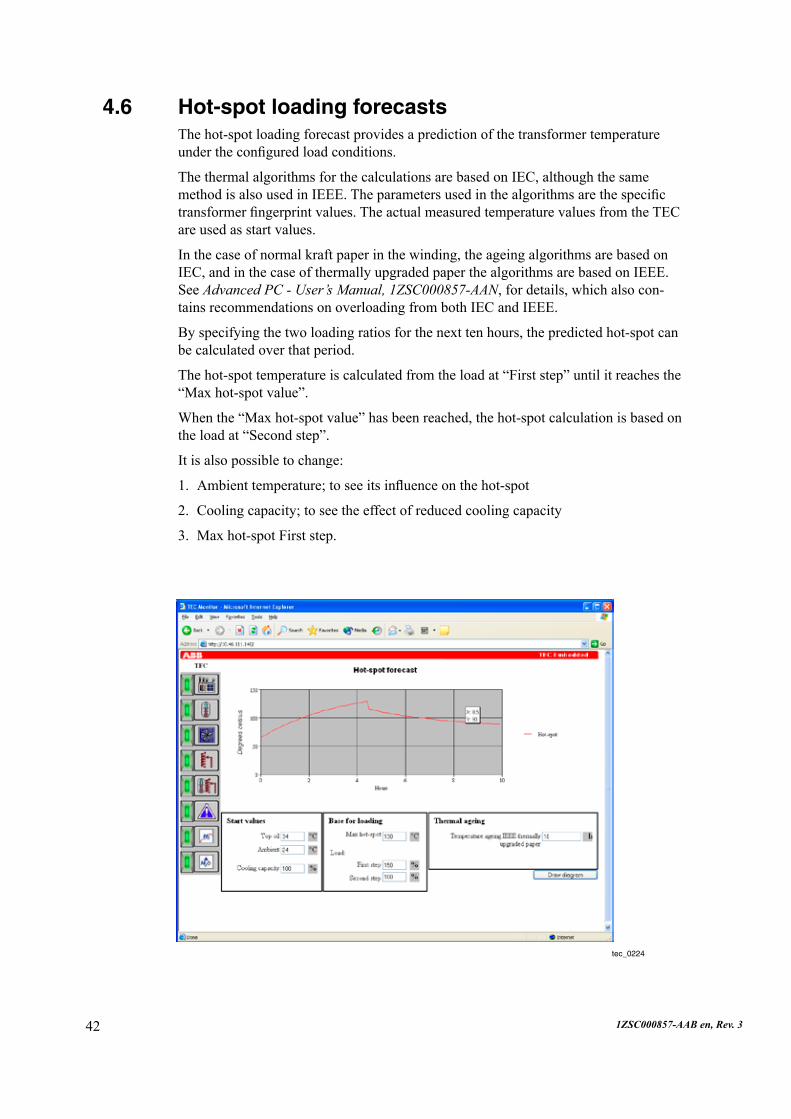
4.6 Hot-spot loading forecastsThe hot-spot loading forecast provides a prediction of the transformer temperature undertheconfiguredloadconditions.
The thermal algorithms for the calculations are based on IEC, although the same methodisalsousedinIEEE.Theparametersusedinthealgorithmsarethespecifictransformerfingerprintvalues.TheactualmeasuredtemperaturevaluesfromtheTECareusedasstartvalues.
In the case of normal kraft paper in the winding, the ageing algorithms are based on IEC,andinthecaseofthermallyupgradedpaperthealgorithmsarebasedonIEEE.See Advanced PC - User’s Manual, 1ZSC000857-AAN, for details, which also con-tainsrecommendationsonoverloadingfrombothIECandIEEE.
By specifying the two loading ratios for the next ten hours, the predicted hot-spot can becalculatedoverthatperiod.
Thehot-spottemperatureiscalculatedfromtheloadat“Firststep”untilitreachesthe“Maxhot-spotvalue”.
Whenthe“Maxhot-spotvalue”hasbeenreached,thehot-spotcalculationisbasedontheloadat“Secondstep”.
It is also possible to change:
Ambienttemperature;toseeitsinfluenceonthehot-spot
Cooling capacity; to see the effect of reduced cooling capacity
Maxhot-spotFirststep.
1.
2.
3.
tec_0224

431ZSC000857-AAB en, Rev. 3
4.7 Tap-changer contact wearThe contact wear function keeps track of the wear on each contact during operation, andcalculateshowmuchmaterialhasbeenwornoff.Fromthisinformationitcal-culatesoperatingtimeandtimetonextservice/contactreplacement.Astheseeventsapproach, warnings are provided, and if actions are not taken in due time, alarms are generated.Thisfunctionshouldbeusedasaforecasterandreminderforwhenover-haulandcontactreplacementisrequired.Thisisespeciallyimportantfortransform-erswithfrequenttap-changeruse,wheremoreregularserviceisrequired.Insteadofperformingservicebasedonoperationtime(1/5ofthecontactlife),theTECestimateswhen1/5ofthecontactsareworn.Thiswillprolongthetimebetweenservicingwith-outjeopardizingtap-changerfunctionality.
tec_0225
44 1ZSC000857-AAB en, Rev. 3
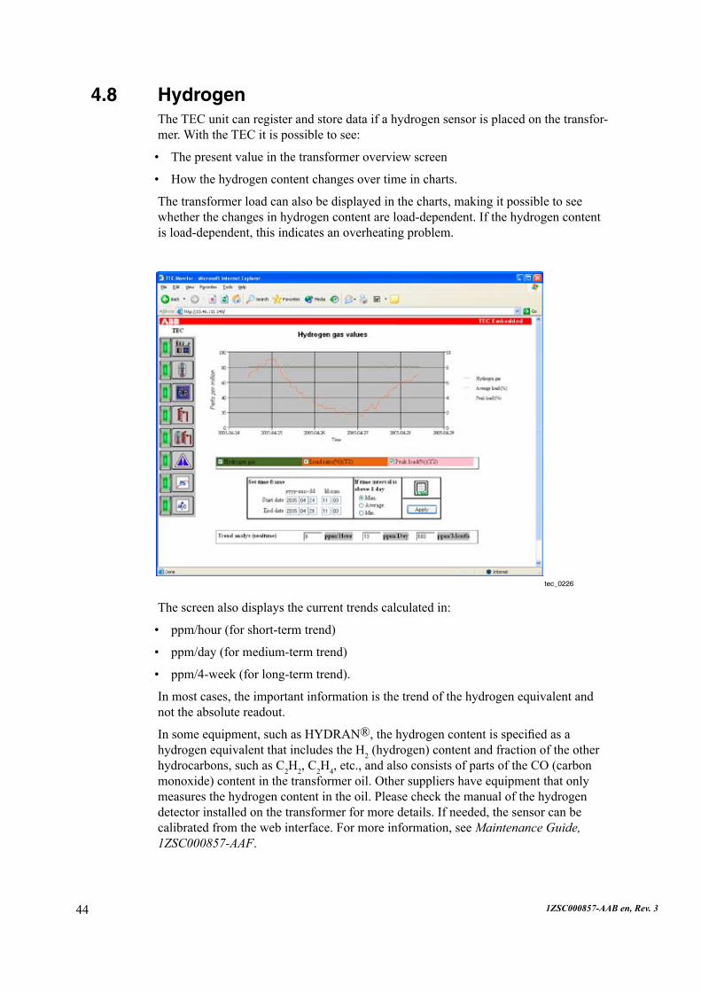
4.8 Hydrogen The TEC unit can register and store data if a hydrogen sensor is placed on the transfor-mer.WiththeTECitispossibletosee:
The present value in the transformer overview screen
Howthehydrogencontentchangesovertimeincharts.
The transformer load can also be displayed in the charts, making it possible to see whetherthechangesinhydrogencontentareload-dependent.Ifthehydrogencontentisload-dependent,thisindicatesanoverheatingproblem.
•
•
The screen also displays the current trends calculated in:
ppm/hour (for short-term trend)
ppm/day (for medium-term trend)
ppm/4-week(forlong-termtrend).
In most cases, the important information is the trend of the hydrogen equivalent and nottheabsolutereadout.
In some equipment, such as HYDRAN®,thehydrogencontentisspecifiedasahydrogen equivalent that includes the H2 (hydrogen) content and fraction of the other hydrocarbons, such as C2H2, C2H4,etc.,andalsoconsistsofpartsoftheCO(carbonmonoxide)contentinthetransformeroil.Othersuppliershaveequipmentthatonlymeasuresthehydrogencontentintheoil.Pleasecheckthemanualofthehydrogendetectorinstalledonthetransformerformoredetails.Ifneeded,thesensorcanbecalibratedfromthewebinterface.Formoreinformation,seeMaintenance Guide, 1ZSC000857-AAF.
•
•
•
tec_0226
451ZSC000857-AAB en, Rev. 3
tec_0227
4.9 Moisture content in the transformer and tap-changer oil
The TEC unit can register and store data if a moisture sensor is placed on the trans-formerorthetap-changer.Itcancalculatethemoisturecontentinthetransformeroilinppmifpreferredtorelativehumidityorwateractivity.NodisplayisneededonthemoisturesensorasthevaluesareshownontheTECdisplayandinthewebinterface.Historicalvaluesaredisplayedinthewebinterface.Anyincreaseinmoisturecontentinthetransformercanbeseeninthecharts.
For the tap-changer the moisture content in oil is the most important reason for service atcertaintimeintervals.
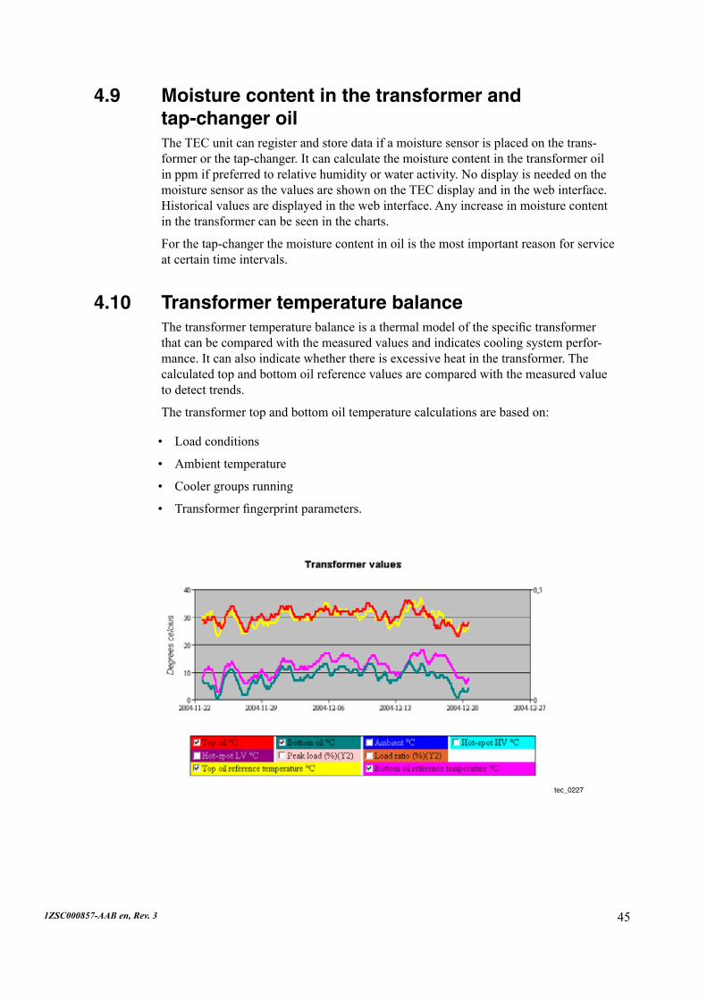
4.10 Transformer temperature balanceThetransformertemperaturebalanceisathermalmodelofthespecifictransformerthat can be compared with the measured values and indicates cooling system perfor-mance.Itcanalsoindicatewhetherthereisexcessiveheatinthetransformer.Thecalculated top and bottom oil reference values are compared with the measured value todetecttrends.
The transformer top and bottom oil temperature calculations are based on:
Load conditions
Ambient temperature
Cooler groups running
Transformerfingerprintparameters.
•
•
•
•

46 1ZSC000857-AAB en, Rev. 3
4.11 Tap-changer temperature balanceThetap-changertemperaturebalanceisathermalmodelofthespecifictransformerand tap-changer that can be compared with the measured tap-changer temperature values.Incasesofexcessiveheatgenerationinthetap-changeroveralongerperiod,thisclearlyindicatesafaultinthetap-changer.
The tap-changer oil temperature calculation is based on:
Load
Heat from switching operations
Ambient temperature
Transformer temperatures
Fingerprintparameters.
•
•
•
•
•
4.12 On-site configurationSomeconfigurationcanbeperformedon-site.NewsensorscanbeconnectedtotheTECafterdelivery.Warningandalarmlevels,aswellassomeotherdata,canbechangedafterdelivery.Thecoolingsystemparametersarealsoeasilychanged.
TheinformationinthedisplayiseasilyconfiguredfromaPCtoshowotheravailableinformation.
4.13 Event handlingTherearefourtypesofeventlevelintheTECsystem.
Note events are used for indication type activities and can, for example, beusedtoindicatethattheTECortransformerdoorisopen.
•
tec_0228

471ZSC000857-AAB en, Rev. 3
Warning events are an indication that something minor has happened that could de-velopintoamoresevereproblem,suchasthetopoilstartingtoheatup.Theyalsoindicatesensormalfunctions.AwarningresultsinasmallflashingWarningsigntotheleft/rightoftheaffectedvaluefieldontheOverviewaswellasontheaffectedquicktabs.
AlarmeventsindicateaseriousproblemwiththetransformerortheTECsystem.For example, an alarm event is generated when the top oil temperature climbs to adangerouslevel.Therecommendationistoexaminethecauseandevaluatethesituation.AnalarmresultsinasmallflashingAlarmsigntotheleft/rightoftheaf-fectedvaluefieldontheOverviewaswellasontheaffectedquicktabs.
Tripeventsindicatesevereproblemswiththetransformer.Therecommendationistopowerdownthetransformerandexaminethecause.AtripindicationresultsinasmallflashingTripsigntotheleft/rightoftheaffectedvaluefieldontheOverviewaswellasontheaffectedquicktabs.
4.13.1 Event listTheeventsareshownintheeventlistinthegraphicinterfaceandonthelocaldisplay.Inthewebinterfacetheorderofeventscanbeseenwitharesolutionof1ms.
•
•
•
Oncethecauseofaneventhasbeenremedied,theeventsignalcanbedeactivatedfromthewebinterface.Deactivatedeventsarestored,withspaceformorethan 4,000eventsintheunit.
tec_0229

48 1ZSC000857-AAB en, Rev. 3
4.13.2 ProtectionThe TEC system can generate relay output signals for the protection of the control system.Theoutputsaredependentonevents,eitherinternalorexternal,andcanbeindividualorgrouped.
AllexternalprotectiondevicescanbeconnectedtotheTEC.AllconnecteddevicesappearintheTECeventlist.TheywillalsobepartofthesignalsforthedrycontactsrepresentingTrip,Alarm,andWarning.ExternalTripsignalswillbegalvanicallyconnected in the TEC terminals so that the sum Trip signal will be sent from the TEC cabineteveniftheTECisswitchedoff.
4.13.3 Sensor backupThereisasensorback-upintheTECincaseofsensorfailure.IfthereadingfromaPt100sensorisoutofrange(-50–150°C)for1minute,aback-upwilltakeplaceasdescribedbelow.AWarningwillbegivenandthenameofthefailedsensordisplayedintheeventlist.IfthePt100sensorisreplaceditwillstarttoworkafterapproximately30seconds.
Ifa4–20mAsensorisoutofrange,i.e.thereadingis<3.5mAor>22mA,aWarningisgivenandthenameofthefailedsensorisdisplayedintheeventlist.Thefalsesen-sorreadingwillnotbedisplayed.Ifthesensorisreplaceditwillstarttoworkafter 30seconds.Forthecurrentsensors,seealsothelogicbelow.
Top oil thermometer failure
If the sensor fails, the top oil temperature is calculated based on the bottom oil tem-perature.Understableconditionsthecalculatedtemperaturewillberelativelyclosetotheactualtemperature.Duringrapidloadincreases,however,thecalculatedtopoiltemperaturewillincreasemuchmorequicklythantheactualtemperature.To avoid a premature trip in such cases, the top oil trip is disabled, although the alarm and warning signals will still work. Asensorfailurewarningwillbegenerated.
ΘTop=ΘBot+2[∆Θimr - ∆Θbr]Ky
tec_0230

491ZSC000857-AAB en, Rev. 3
Bottom oil thermometer failure
If the sensor fails, the bottom oil temperature is calculated based on the top oil tem-perature.Asensorfailurewarningwillbegenerated.
ΘBot=ΘTop-2[∆Θimr - ∆Θbr]Ky
Both top and bottom oil thermometers fail
Ifbothsensorsfail,asensorfailurealarmwillbegeneratedintheTEC.
Ambient air thermometer failure
If the shade sensor fails, the value from the sun sensor will be displayed and used for thecalculations.Ifthesunsensorfails,thevaluefromtheshadesensorwillbedis-played.
Ifonesensorfails,awarningisgiven.Ifbothsensorsfail,awarningisstillgivenandthesensoroutputspriortofailurearedisplayed.
Current sensors
Therearethreedifferenttypesofbehaviorinthecaseofsensorerrors.
A two-winding transformer sensor error will be compensated by the calculation of thefaultycurrent,basedontheothercurrentsensor.Thecalculationisbasedontheremainingcurrent,thetransformerratio,andthetap-changerposition.
Forallotherconnectiontypestherewillnotbeanycurrentcalculation.Thefaultysen-sorwilldisplay“0”.
For autotransformers a current sensor failure on the series winding will result in a cur-rentreadingof“0”frombothcurrentsensors.IfthecurrentsensorontheLVsideorcommonwindingfails,theoutputfromthissensorwillbe“0”,buttheoutputfromtheseriescurrentsensorwillbecorrect.
Ifonecurrentsensorfails,awarningisgiven.Ifbothsensorsfail,analarmisgener-ated.
4.13.3.1 Effect of sensor failure on functions
Hot-spot temperature calculation
The hot-spot temperatures for the high-voltage and low-voltage windings are always calculated.Ifathermometerorcurrenttransformersensorfails,thelostvaluewillbecalculated by the formulas in the previous sections and will be used for the hot-spot calculations.
Ageing
If the hot-spot temperature of the hottest winding cannot be calculated due, for ex-ample, to a current transformer failure, the second hottest winding will be used for the ageingcalculation.
50 1ZSC000857-AAB en, Rev. 3
4.14 Cabinet conditionsThis function reads the temperature and the relative humidity on the processor board inthecabinet.
The temperature is monitored, as a high temperature is the main cause of in ageing electronics.TheTECisdesignedtoprovidelowtemperatureelectronics.Tofurtherpreventageingsomeofthecomponentsarethermallyupgraded.
The moisture content is monitored even though the boards are coated to resist mois-ture.Thereadingswillbeavailableasbothpresentconditionsandahistogramshow-ingthefrequencyofthedifferenttemperaturesandhumiditylevels.
4.15 CommunicationThe TEC system can simply be connected to a LAN network and viewed from a standardcomputerwithInternetExplorer®.Noadditionalsoftwareisrequired.Thesystemcanalsobeconnectedtoamodemforaccessoverthephone.Therearediffer-entlevelsofpasswordprotectedaccessinthewebinterface.
The TEC system can communicate with external systems using three different meth-ods:Drycontacts,OPC,andXMLfiles.
Cooling control
If the hot-spot temperature of the hottest winding cannot be calculated due, for ex-ample, to a current transformer failure, the second hottest winding will be used for coolingcontrol.
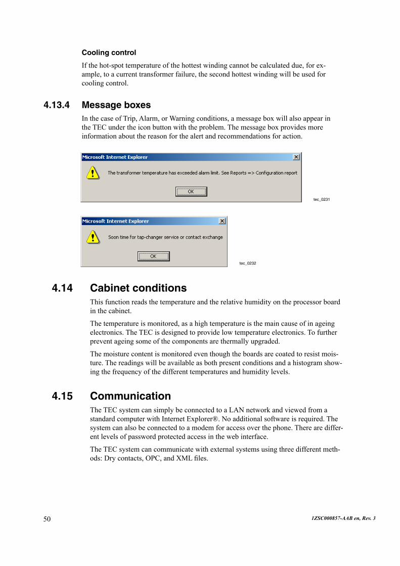
4.13.4 Message boxesIn the case of Trip, Alarm, or Warning conditions, a message box will also appear in theTECundertheiconbuttonwiththeproblem.Themessageboxprovidesmoreinformationaboutthereasonforthealertandrecommendationsforaction.
tec_0231
tec_0232
511ZSC000857-AAB en, Rev. 3
4.16 Configurable inputsThe TEC system is based on a modular structure, which makes it possible to add ad-ditionalsensors.Itispossibletoaddany4-20mA,Pt100,ordigitaldevices.
Forothertypesofsensor,forexampleCANbussensors,contactABB.Theextrasen-sorvalueswillbestoredandthesignaleventlevelscanbeconfigured.
4.17 Ordering dataThespecificationoftheTECsystemisprovidedbyfillingoutaMicrosoftExcel® orderdatasheet.TheordersheetdefinestheconnectionsfortheTECsystem.Italsoprovidesafingerprintsettingofthetransformer.
For more information, see Ordering data Guide, 1ZSC000857-AAG.
4.17.1 Load testIn the event data from the transformer’s hear-run test deviate from calculated values giveninsection2.21Orderingdata,thenewvaluesshallbeaddedtothetransformermodelintheTEC.

52 1ZSC000857-AAB en, Rev. 3
5 InstallationFor more information, see Installation and Commissioning Guide, 1ZSC000857-AAC.
Input parameters
8insulatedanalog4-20mAinputsviaterminals(expandableupto24)
4insulatedPt100directinputs(expandableupto16)
1inputforthevoltagemeasurement(85-140V)
1 input for tap-changer position, resistor bridge Rtot>=80W
12insulateddigitalinputs*byterminals(expandableupto48)
CAN bus possibility, contact ABB
PPS/PPMsynchronizationpulses.
Output parameters
5outputrelays*,fast(ms)relays,3usedforwarningalarmandtrip
Up to 12 output relays*, slow (s) relays
Upto6outputsrelays*forcoolercontrolrelays.
*)PermittedloadbreakingcapacityonoutputterminalsAC250V8A, DC250V0,1AL/R=40ms,DC30V5A
5.1 SensorsSensorscanbeincludedinthedelivery.Formoreinformation,seeOrdering data Guide, 1ZSC000857-AAG.
Connectionofthecableshieldisdescribedinsection4.2Cables and earthing.
•
•
•
•
•
•
•
•
•
•

531ZSC000857-AAB en, Rev. 3
5.1.1 Air temperature APt100sensorforairtemperatureinsunandshade.Thesensorintheshademustnotbeaffectedbyheatradiatedfromthetransformer.
APt100sensorthatisreplacedautomaticallystartstoworkafterapproximately 30seconds.
Thebushingthatisincludedinthedeliveryisforacablediameterof4–8mm.Ifalargercablediameterisuseditshouldbeprovidedbythecustomer.
T (°C) Pt100(W) -40 84.3 -30 88.2 -20 92.2 -10 96.1 0 100.0 10 103.9 20 107.8 30 111.7 40 115.5 50 119.4 60 123.2 70 127.1 80 130.9 90 134.7 100 138.5 110 142.3 120 146.0 130 149.8 140 153.5 150 157.2 160 160.9
Temperature input Pt100
Height with cover: 37
64
57
tec_0104
46
Ø 4.5 (2x)
Shade sensor 9 11 10 12Sun sensor 13 15 14 16
36.5

54 1ZSC000857-AAB en, Rev. 3
5.1.2 Oil temperature
Pt100sensorforoiltemperaturesatthetopandbottomofthetransformerandinthetap-changer.Thethermometerpocketisincludedwiththetemperaturesensor.Orderasensorforthetap-changertogetherwiththetap-changer.Recommendationsforther-mometer placement:
Should be placed level with the lower spacer ring (to avoid the cooler non-moving bottomoil).
Should not be placed too far away from the cooler/radiator outlet (to measure in movingoil).
5.1.2.1 Use of TEC bottom oil sensor
The TEC bottom oil sensor shouldnot be used in the calculations from the heat run test, but the temperature should benoted.Thecalculationofaverageoiltemperatureetc.shouldbecarriedoutinthenormalway.InthecaseofOFandODcooled transformers in service, the TEC will calculate the hot-spot from the TEC bottom oil thermometer and the calculated valuesfromtheheatruntest.Thebottomoil sensor must be assembled at a position where the reading represents the tempera-tureoftheoilenteringthewindings.
•
•
tec_0059
88
166
169
7/8”-14UNF2
Ø = 12.21±0.05KR 1”
Ø = 13.83±0.07
84
1 3 2 4
Conductor no. in section 3.3.5 Temperature input Pt100 tec_0060
84
551ZSC000857-AAB en, Rev. 3
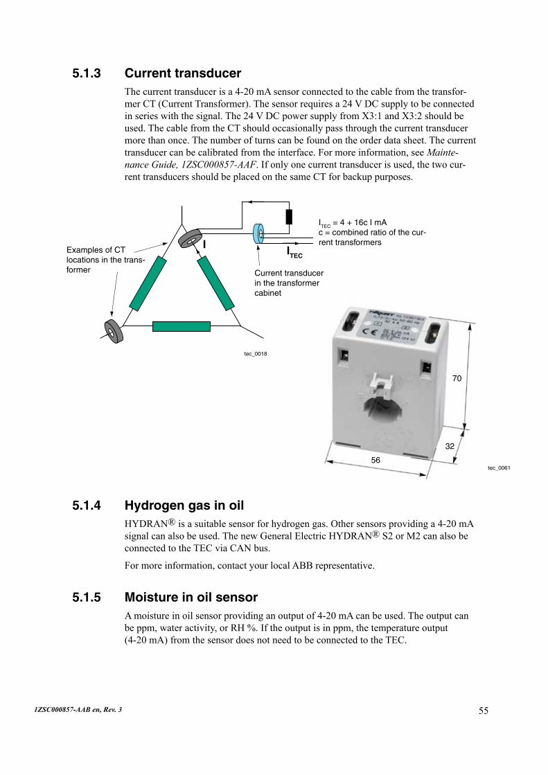
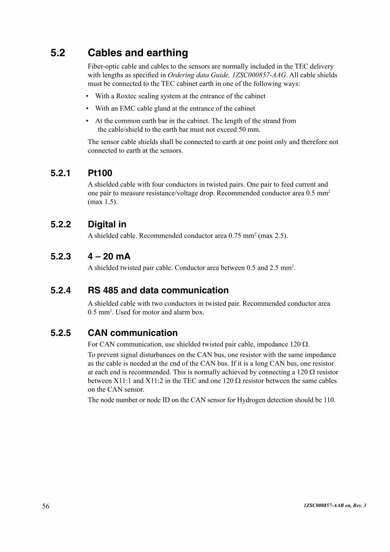
5.1.3 Current transducerThecurrenttransducerisa4-20mAsensorconnectedtothecablefromthetransfor-merCT(CurrentTransformer).Thesensorrequiresa24VDCsupplytobeconnectedinserieswiththesignal.The24VDCpowersupplyfromX3:1andX3:2shouldbeused.ThecablefromtheCTshouldoccasionallypassthroughthecurrenttransducermorethanonce.Thenumberofturnscanbefoundontheorderdatasheet.Thecurrenttransducercanbecalibratedfromtheinterface.Formoreinformation,seeMainte-nance Guide, 1ZSC000857-AAF.Ifonlyonecurrenttransducerisused,thetwocur-renttransducersshouldbeplacedonthesameCTforbackuppurposes.
tec_0018
ITEC = 4 + 16c I mA c = combined ratio of the cur-rent transformers
Current transducer in the transformer cabinet
Examples of CT locations in the trans-former
I ITEC
tec_0061
70
32
56
5.1.4 Hydrogen gas in oilHYDRAN®isasuitablesensorforhydrogengas.Othersensorsprovidinga4-20mAsignalcanalsobeused.ThenewGeneralElectricHYDRAN® S2 or M2 can also be connectedtotheTECviaCANbus.
Formoreinformation,contactyourlocalABBrepresentative.
5.1.5 Moisture in oil sensorAmoistureinoilsensorprovidinganoutputof4-20mAcanbeused.Theoutputcanbeppm,wateractivity,orRH%.Iftheoutputisinppm,thetemperatureoutput (4-20mA)fromthesensordoesnotneedtobeconnectedtotheTEC.
56 1ZSC000857-AAB en, Rev. 3
5.2 Cables and earthingFiber-optic cable and cables to the sensors are normally included in the TEC delivery withlengthsasspecifiedinOrdering data Guide, 1ZSC000857-AAG.Allcableshieldsmust be connected to the TEC cabinet earth in one of the following ways:
With a Roxtec sealing system at the entrance of the cabinet
With an EMC cable gland at the entrance of the cabinet
Atthecommonearthbarinthecabinet.Thelengthofthestrandfrom thecable/shieldtotheearthbarmustnotexceed50mm.
The sensor cable shields shall be connected to earth at one point only and therefore not connectedtoearthatthesensors.
5.2.1 Pt100Ashieldedcablewithfourconductorsintwistedpairs.Onepairtofeedcurrentand onepairtomeasureresistance/voltagedrop.Recommendedconductorarea0.5mm2 (max1.5).
5.2.2 Digital inAshieldedcable.Recommendedconductorarea0.75mm2(max2.5).
5.2.3 4 – 20 mAAshieldedtwistedpaircable.Conductorareabetween0.5and2.5mm2.
5.2.4 RS 485 and data communicationAshieldedcablewithtwoconductorsintwistedpair.Recommendedconductorarea 0.5mm2.Usedformotorandalarmbox.
5.2.5 CAN communicationFor CAN communication, use shielded twisted pair cable, impedance 120 W.To prevent signal disturbances on the CAN bus, one resistor with the same impedance asthecableisneededattheendoftheCANbus.IfitisalongCANbus,oneresistorateachendisrecommended.Thisisnormallyachievedbyconnectinga120W resistor betweenX11:1andX11:2intheTECandone120W resistor between the same cables ontheCANsensor.ThenodenumberornodeIDontheCANsensorforHydrogendetectionshouldbe110.
•
•
•
571ZSC000857-AAB en, Rev. 3
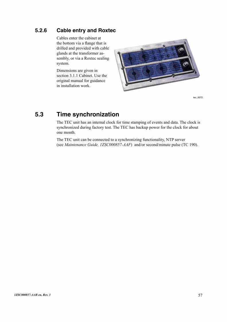
5.2.6 Cable entry and RoxtecCables enter the cabinet at thebottomviaaflangethatisdrilled and provided with cable glands at the transformer as-sembly, or via a Roxtec sealing system.
Dimensions are given in section3.1.1Cabinet.Usetheoriginal manual for guidance ininstallationwork.
5.3 Time synchronizationTheTECunithasaninternalclockfortimestampingofeventsanddata.Theclockissynchronizedduringfactorytest.TheTEChasbackuppowerfortheclockforaboutonemonth.
TheTECunitcanbeconnectedtoasynchronizingfunctionality,NTPserver (see Maintenance Guide, 1ZSC000857-AAF)and/orsecond/minutepulse(TC190).
tec_0072
58 1ZSC000857-AAB en, Rev. 3
6 TEC Advanced PCTheAdvancedPCisanextensiontotheTECsystem.
It increases the functionality of the TEC system in three important areas:
Extended data storage
Single interface to the transformer together with protocol converter
PortalformultipleTECunits.
Otherfunctionsare:
Improved user interface
Improved overload prediction
Documentation and video capabilities
Onlineservicelogfunctionality.
TheAdvancedPCisthecommoninterfacetoeachtransformerconnectedtothecomputer,bothforthepersonnelandforthecontrolsystem.TheinformationfromtheTEC systems and connected third party specialized sensors are stored in a database ontheAdvancedPCandcaneasilybeviewedandanalyzedintheTECAdvancedPCwebinterface.ThewebinterfacecanbeviewedfromanyPCconnectedtothesamenetworkastheAdvancedPC.
The extended data storage makes it possible to follow the transformer service condi-tions during its whole lifetime and with higher sampling frequency compared to the TEC.Dangeroustrendsandotherproblematicdevelopmentsaremoreeasilymoni-toredandprevented.
TheinformationstreamedfromtheTECunitstotheAdvancedPCcanbeconvertedanddistributedtoothersystems,forexampleSCADA,directlyindataformat.TheAdvancedPCcanbeusedasthesingleinterfacetothetransformer.Alltransformerdataandimportantevaluatationsarepresentedfromasinglesystem.
For more information, see Advanced PC - User’s Manual, 1ZSC000857-AAN.
•
•
•
•
•
•
•


1ZS
C00
0857
-AA
B e
n, R
ev. 3
, 200
8-02
-06
ABB AB ComponentsVisitors: Lyviksvägen 10Postaddress: SE-771 80 Ludvika, SWEDENTel. +46 240 78 20 00Fax +46 240 121 57E-mail: [email protected]/electricalcomponents


