Typical Deck Details YOU CAN USE TO BUILD YOUR DECK (Valid for 2008, check for annual updates) Introduction ........................................2 Lateral Support of Decks .................... 13 Obtaining Permits ...............................2 Joist Hangers ..................................... 14 General Notes ....................................2 Rim Joist Requirements ..................... 14 Getting Started ...................................4 Built-up Beam Requirements ............. 14 Beam, Joist, and Footing Sizes ..........4 Post-to-Beam Requirements .............. 15 Post Sizes ..........................................8 Footings ............................................. 15 Ledger Attachment Requirements ......8 Guardrail Requirements ..................... 16 Prohibited Ledger Attachments ........10 Stair Requirements............................. 18 Ledger Board Fasteners...................11 Stair Handrail Requirements .............. 19 Freestanding Decks .........................12 Framing at Chimney or Bay Window .. 20 Name: Permit No: Address: Typical Deck Details revised 2/08 Page 1 of 27 The use of this typical deck detail package in lieu of submitted drawings applies to single span, one level, single-family residential decks only . Decks must be constructed in strict conformance with the details contained herein. If a permit is required, a copy of this deck detail package must be on the job site and available to the inspector during the inspection process. This guide is intended to help provide typical information needed for constructing a deck; however, you will need to have at least some understanding of typical construction practices in order to complete the project.
Transcript
Typical Deck Details YOU CAN USE TO BUILD YOUR DECK
(Valid for 2008, check for annual updates)
Introduction ........................................2 Lateral Support of Decks.................... 13 Obtaining Permits...............................2 Joist Hangers ..................................... 14 General Notes ....................................2 Rim Joist Requirements ..................... 14 Getting Started ...................................4 Built-up Beam Requirements ............. 14 Beam, Joist, and Footing Sizes..........4 Post-to-Beam Requirements .............. 15 Post Sizes ..........................................8 Footings ............................................. 15 Ledger Attachment Requirements......8 Guardrail Requirements ..................... 16 Prohibited Ledger Attachments ........10 Stair Requirements............................. 18 Ledger Board Fasteners...................11 Stair Handrail Requirements .............. 19 Freestanding Decks .........................12 Framing at Chimney or Bay Window.. 20
Name: Permit No:
Address:
Typical Deck Details revised 2/08 Page 1 of 27
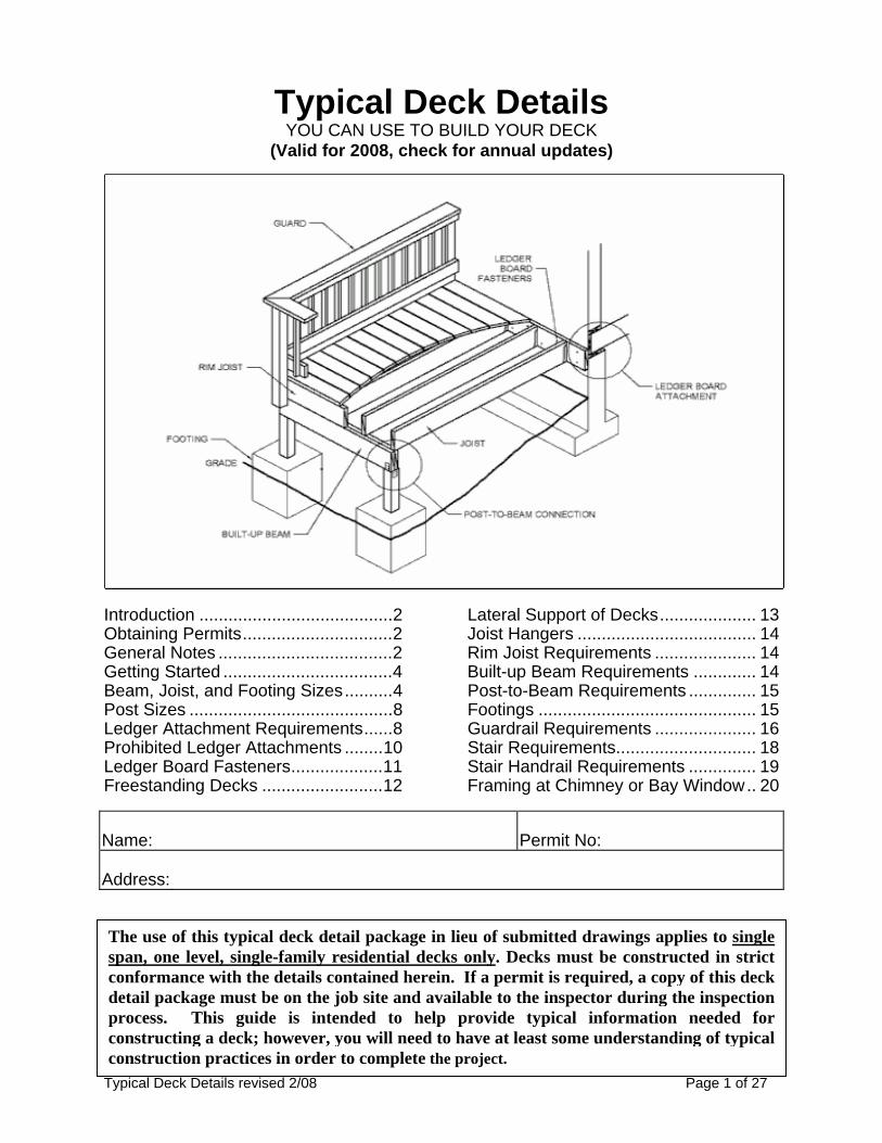
The use of this typical deck detail package in lieu of submitted drawings applies to single span, one level, single-family residential decks only. Decks must be constructed in strict conformance with the details contained herein. If a permit is required, a copy of this deck detail package must be on the job site and available to the inspector during the inspection process. This guide is intended to help provide typical information needed for constructing a deck; however, you will need to have at least some understanding of typical construction practices in order to complete the project.
Typical Deck Details revised 2/08 Page 2 of 27
INTRODUCTION These plans and details are provided to assist you in your deck construction, for obtaining a building permit (when required), or simply to aid you in constructing a deck that does not require a permit. Before proceeding, always check with your local jurisdiction for land use, zoning, or other regulations that may affect your project. When Do I Need A Permit For A Deck? A building permit is required for all decks that are 30 inches or more above grade. A building permit is not required for decks that are less than 30 inches above the ground and not less than 3 feet from a property line. How Do I Use The Plans To Get A Permit? If you need a building permit for your deck, you will need to submit plans of sufficient detail to your local building department to indicate what you want to build. If you are not sure how to draw plans, these plans can be submitted to your local building department for the permit. You will, however, be required to follow the plans and details as provided without any deviation. One thing that will be needed is a site plan that shows an outline of your property (property lines), the house, and outline of where you will be locating the deck and how it will appear. Be sure to indicate any additional existing accessory buildings or structures (shed, pool, retaining walls, etc.). The site plans will need to be drawn to an acceptable scale (you may need to contact your local building department for this), but usually a scale of 1/8th or 1/4th of an inch equal to one foot or similar is acceptable. Fill out a building permit application, and submit these plans (along with your site plan). After the plans are reviewed and approved, a permit to construct your deck will be issued (some jurisdictions may even be able to review and approve your plans at the counter, so you can leave with a permit the same day). Consult your local city/county jurisdiction for the number of sets of plans required. For information on contacting your local building departments, visit www.BCD.Oregon.gov, and click on Jurisdictions. How Big Do The Footings, Beams, And Joists Need To Be? The detail in these plans will help you determine how big the footings, beams, joists, posts, and ledgers need to be. Much of it depends on the size of the deck, what size beams and joists you want to use, and how far apart you want to place the beams, posts, and footings. General Notes 1. All lumber shall be grade #2 Douglas-Fir, Hem-Fir, or better and shall be pressure
treated (to resist insect and dry rot) in accordance with American Wood-Preservers’ Association Standards (Category). Decking material of redwood or cedar does not require pressure treatment as it has a natural resistance to decay. The pressure-treatment category identified below will be identified on the lumber. The level of treatment depends on the use as follows: a. Decking material, railings, joists, and beams must be treated to a Category
UC3B. b. Posts and other woods located on, in, or in contact with the ground must be a
Category UC4B. c. Any wood less than six inches above the ground or in contact with concrete must
be a Category UC4A.
Typical Deck Details revised 2/08 Page 3 of 27
2. The level of preservative treatment is noted on the tags fixed to the ends of the wood members. Remember, any time you make a cut, treat the cut end of the wood with a paint-on preservative. Cut ends expose the inner untreated wood to potential moisture and insect damage.
3. All nails shall be “common” or “box” galvanized. It is recommended that “common” nails be used. They have a thicker shank and are stronger than “box” nails.
4. New pressure treatment methods use chemicals that will prematurely corrode standard fasteners, hardware, and flashing when in contact with pressure treated lumber; and as a result, fastener and hardware requirements have changed. Note the following: a. All screws and nails shall be hot-dipped galvanized or stainless steel. b. All hardware (joist hangers, cast-in-place post anchors, etc.) shall be
galvanized with 1.85 oz/sf of zinc (G-185 coating) or shall be stainless steel. Look for products such as "Zmax" from Simpson Strong-Tie or "Triple Zinc" from USP.
5. Decks constructed according to this handout are not designed to support spas or hot tubs. Installation of spas or hot tubs will require additional structural supports.
6. Decks shall not be attached to house overhangs, bay windows, brick veneers, or
chimneys.
7. Deck designs that deviate from the conditions of this handout will require a specific plan submission and may require engineering.
8. Inspections: a. A footing, framing, and a final inspection are required on all decks. b. Footing inspections are required PRIOR to the placement of concrete. c. Framing and final inspections may be combined if all portions of the deck framing
and mechanical attachments are at least four feet above grade. d. It is the responsibility of the permit holder or the permit holder's representative to
notify the city/county who issued the permit when stages of construction are reached that require an inspection. For information on contacting your local building departments, visit www.BCD.Oregon.gov and click on “Jurisdictions.”
9. All decking material shall be composed of 2x4, 2x6, or five quarter (“5/4”) boards. Attach decking to each joist with two 10d nails or two #8 screws. Decking may be placed from an angle perpendicular to the joists to an angle of 45 degrees to the joists. Decking must have a span length such that each board bears on a minimum of two joists.
10. Plastic or composite decking products may be used as a substitute for conventional wood decking, but installation and span lengths of the substituted material must be in strict conformance with the product listing and the manufacturer's installation instructions. Copies of the manufacturer's installation instructions must be submitted with this handout and permit application.
Typical Deck Details revised 2/08 Page 4 of 27
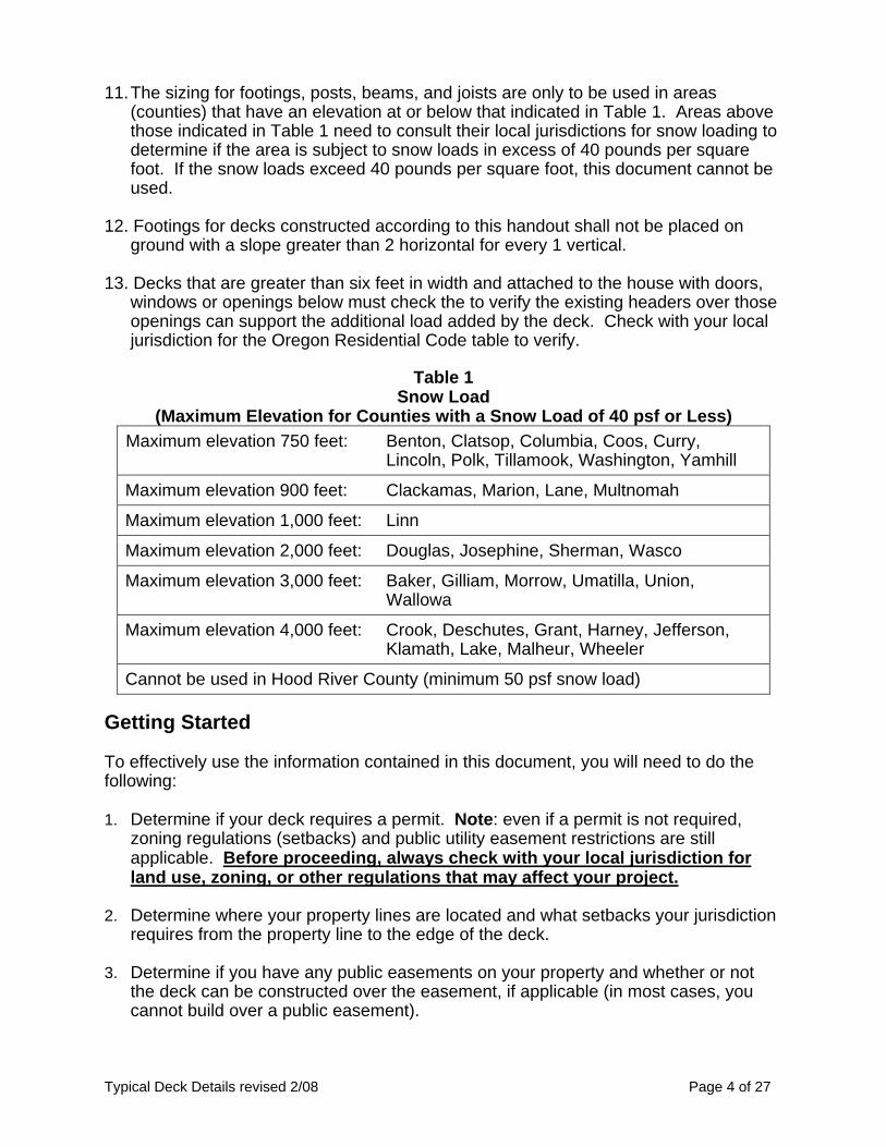
11. The sizing for footings, posts, beams, and joists are only to be used in areas (counties) that have an elevation at or below that indicated in Table 1. Areas above those indicated in Table 1 need to consult their local jurisdictions for snow loading to determine if the area is subject to snow loads in excess of 40 pounds per square foot. If the snow loads exceed 40 pounds per square foot, this document cannot be used.
12. Footings for decks constructed according to this handout shall not be placed on
ground with a slope greater than 2 horizontal for every 1 vertical. 13. Decks that are greater than six feet in width and attached to the house with doors,
windows or openings below must check the to verify the existing headers over those openings can support the additional load added by the deck. Check with your local jurisdiction for the Oregon Residential Code table to verify.
Table 1
Snow Load (Maximum Elevation for Counties with a Snow Load of 40 psf or Less)
Maximum elevation 900 feet: Clackamas, Marion, Lane, Multnomah
Maximum elevation 1,000 feet: Linn
Maximum elevation 2,000 feet: Douglas, Josephine, Sherman, Wasco
Maximum elevation 3,000 feet: Baker, Gilliam, Morrow, Umatilla, Union, Wallowa
Maximum elevation 4,000 feet: Crook, Deschutes, Grant, Harney, Jefferson, Klamath, Lake, Malheur, Wheeler
Cannot be used in Hood River County (minimum 50 psf snow load) Getting Started To effectively use the information contained in this document, you will need to do the following: 1. Determine if your deck requires a permit. Note: even if a permit is not required,
zoning regulations (setbacks) and public utility easement restrictions are still applicable. Before proceeding, always check with your local jurisdiction for land use, zoning, or other regulations that may affect your project.
2. Determine where your property lines are located and what setbacks your jurisdiction requires from the property line to the edge of the deck.
3. Determine if you have any public easements on your property and whether or not the deck can be constructed over the easement, if applicable (in most cases, you cannot build over a public easement).
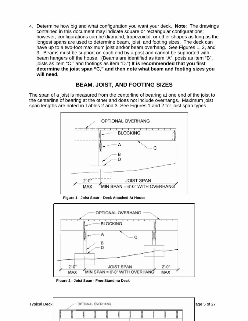
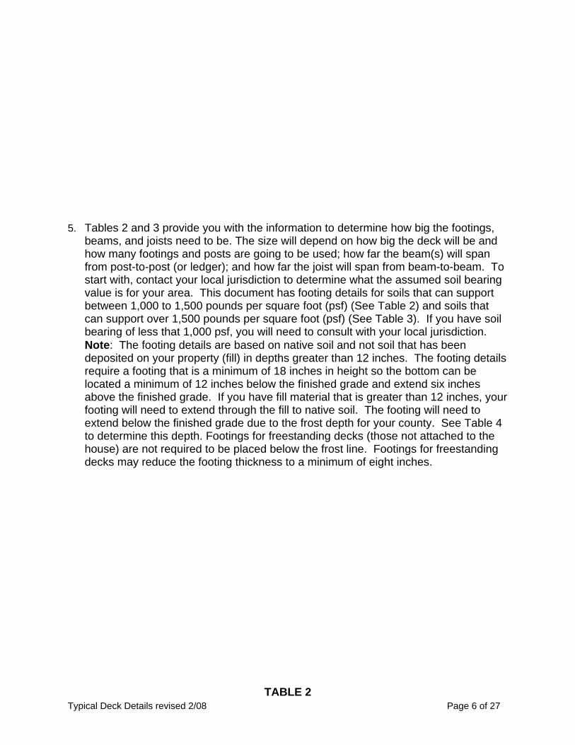
4. Determine how big and what configuration you want your deck. Note: The drawings contained in this document may indicate square or rectangular configurations; however, configurations can be diamond, trapezoidal, or other shapes as long as the longest spans are used to determine beam, joist, and footing sizes. The deck can have up to a two-foot maximum joist and/or beam overhang. See Figures 1, 2, and 3. Beams must be support on each end by a post and cannot be supported with beam hangers off the house. (Beams are identified as item “A”, posts as item “B”, joists as item “C,” and footings as item “D.”) It is recommended that you first determine the joist span “C,” and then note what beam and footing sizes you will need.
BEAM, JOIST, AND FOOTING SIZES
The span of a joist is measured from the centerline of bearing at one end of the joist to the centerline of bearing at the other and does not include overhangs. Maximum joist span lengths are noted in Tables 2 and 3. See Figures 1 and 2 for joist span types.
Typical Deck Details revised 2/08 Page 5 of 27
Figure 1 - Joist Span – Deck Attached At House Figure 2 - Joist Span - Free-Standing Deck
Typical Deck Details revised 2/08 Page 6 of 27
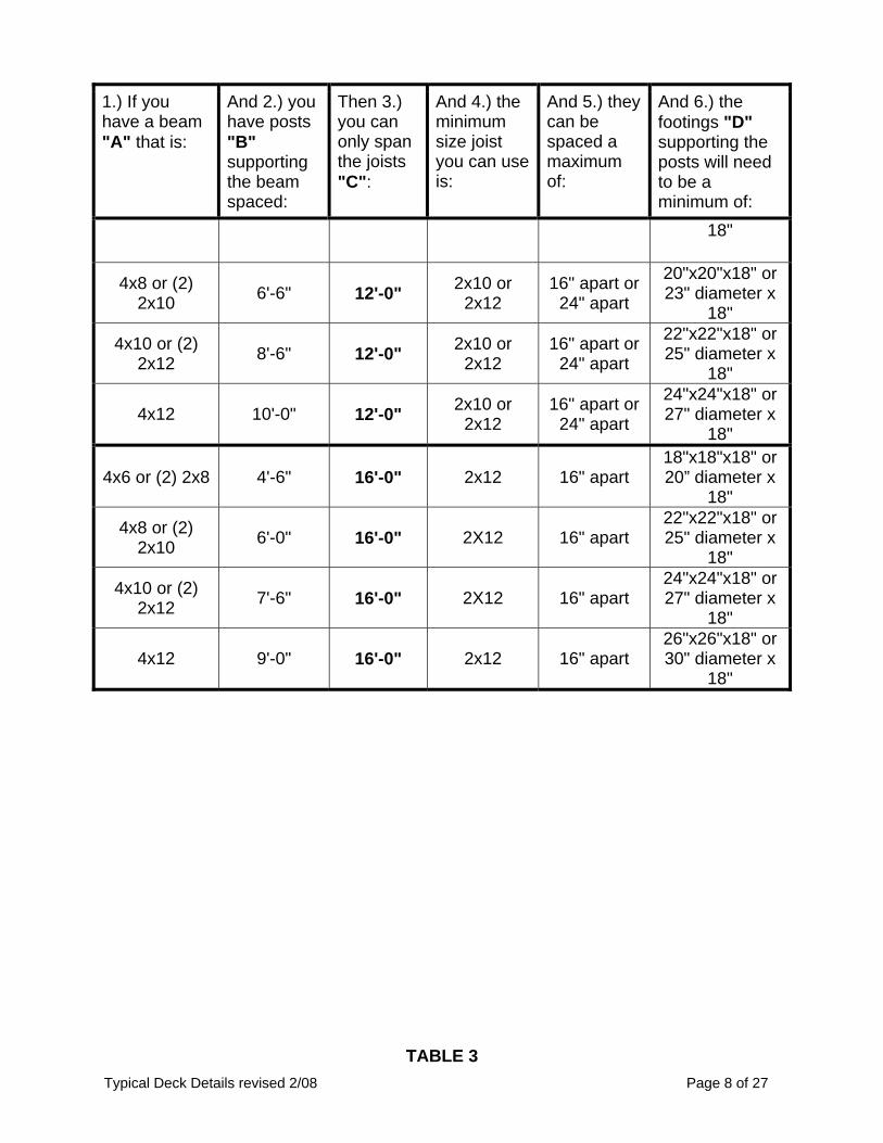
5. Tables 2 and 3 provide you with the information to determine how big the footings,
beams, and joists need to be. The size will depend on how big the deck will be and how many footings and posts are going to be used; how far the beam(s) will span from post-to-post (or ledger); and how far the joist will span from beam-to-beam. To start with, contact your local jurisdiction to determine what the assumed soil bearing value is for your area. This document has footing details for soils that can support between 1,000 to 1,500 pounds per square foot (psf) (See Table 2) and soils that can support over 1,500 pounds per square foot (psf) (See Table 3). If you have soil bearing of less that 1,000 psf, you will need to consult with your local jurisdiction. Note: The footing details are based on native soil and not soil that has been deposited on your property (fill) in depths greater than 12 inches. The footing details require a footing that is a minimum of 18 inches in height so the bottom can be located a minimum of 12 inches below the finished grade and extend six inches above the finished grade. If you have fill material that is greater than 12 inches, your footing will need to extend through the fill to native soil. The footing will need to extend below the finished grade due to the frost depth for your county. See Table 4 to determine this depth. Footings for freestanding decks (those not attached to the house) are not required to be placed below the frost line. Footings for freestanding decks may reduce the footing thickness to a minimum of eight inches.
TABLE 2
Typical Deck Details revised 2/08 Page 7 of 27
DECKS ON SOIL WITH A 1000 PSF TO 1500 PSF BEARING CAPACITY (Note: All footings are to be placed a minimum of 12 inches below the surface
of the finished grade and cannot be placed on fill.) 2x6 joists cannot be used when a guardrail is required.
1.) If you have a beam "A" that is:
And 2.) you have posts "B" supporting the beam spaced:
Then 3.) you can only span the joists "C":
And 4.) the minimum size joist you can use is:
And 5.) they can be spaced a maximum of:
And 6.) the footings "D" supporting the posts will need to be a minimum of:
4x6 or (2) 2x6 6'-0" apart 6'-0" 2x6 24" apart 14"x14"x 18" or 16" diameter x
18"
4x8 or (2) 2x8 8'-6" apart 6'-0" 2x6 24" apart 18x18"x 18" or 20" diameter x
18"
4x10 or (2) 2x12 10'-6" apart 6'-0" 2x6 24" apart
20"x20"x18" or 23" diameter x
18"
4x12 12'-6" apart 6'-0" 2x6 24" apart 22"x22"x18" or 25" diameter x
18"
4x6 or (2) 2x8 6'-0" apart 8'-0" 2x6 or 2x8
16" apart or 24" apart
18x18"x 18" or 20" diameter x
18"
4x8 or (2) 2x10 8'-0" apart 8'-0" 2x6 or
2x8 16" apart or
24" apart
20"x20"x18" or 23" diameter x
18"
4x10 or (2) 2x12 9'-6" apart 8'-0" 2x6 or
2x8 16" apart or
24" apart
22"x22"x18" or 25" diameter x
18"
4x12 11'-0" apart 8'-0" 2x6 or 2x8
16" apart or 24" apart
22"x22"x18" or 25" diameter x
18"
4x6 or (2) 2x8 5'-6" apart 10'-0" 2x8 or 2x10
16" apart or 24" apart
18"x18"x 18" or 20" diameter x
18"
4x8 or (2) 2x10 7'-6" apart 10'-0" 2x8 or
2x10 16" apart or
24" apart
20"x20"x18" or 23" diameter x
18"
4x10 or (2) 2x12 9'-0" apart 10'-0" 2x8 or
2x10 16" apart or
24" apart
22"x22"x18" or 25" diameter x
18"
4x12 10'-6" apart 10'-0" 2x8 or 2x10
16" apart or 24" apart
24"x24"x18" or 27" diameter x
18"
4x6 or (2) 2x8 5'-0" 12'-0" 2x10 or 2x12
16" apart or 24" apart
18"x18"x18" or 20" diameter x
Typical Deck Details revised 2/08 Page 8 of 27
1.) If you have a beam "A" that is:
And 2.) you have posts "B" supporting the beam spaced:
Then 3.) you can only span the joists "C":
And 4.) the minimum size joist you can use is:
And 5.) they can be spaced a maximum of:
And 6.) the footings "D" supporting the posts will need to be a minimum of:
18"
4x8 or (2) 2x10 6'-6" 12'-0" 2x10 or
2x12 16" apart or
24" apart
20"x20"x18" or 23" diameter x
18"
4x10 or (2) 2x12 8'-6" 12'-0" 2x10 or
2x12 16" apart or
24" apart
22"x22"x18" or 25" diameter x
18"
4x12 10'-0" 12'-0" 2x10 or 2x12
16" apart or 24" apart
24"x24"x18" or 27" diameter x
18"
4x6 or (2) 2x8 4'-6" 16'-0" 2x12 16" apart 18"x18"x18" or 20” diameter x
18"
4x8 or (2) 2x10 6'-0" 16'-0" 2X12 16" apart
22"x22"x18" or 25" diameter x
18"
4x10 or (2) 2x12 7'-6" 16'-0" 2X12 16" apart
24"x24"x18" or 27" diameter x
18"
4x12 9'-0" 16'-0" 2x12 16" apart 26"x26"x18" or 30" diameter x
18"
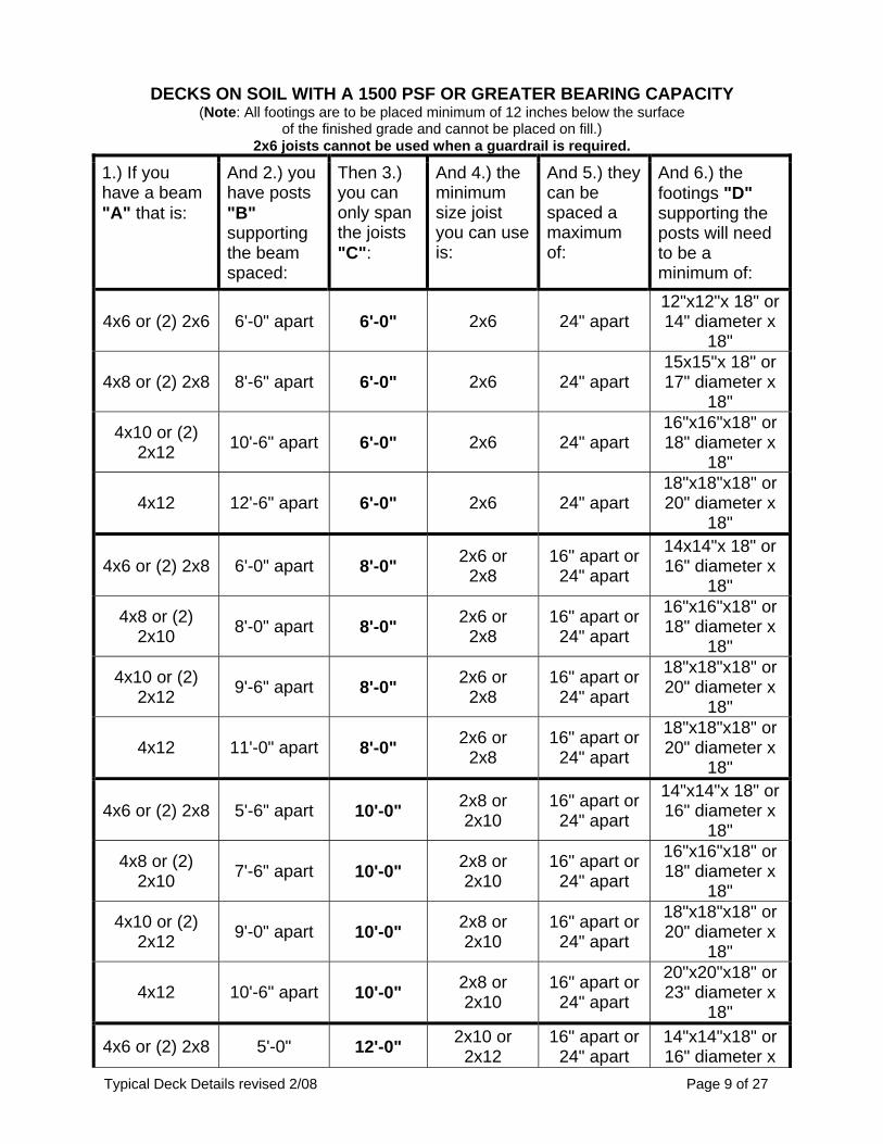
TABLE 3
Typical Deck Details revised 2/08 Page 9 of 27
DECKS ON SOIL WITH A 1500 PSF OR GREATER BEARING CAPACITY (Note: All footings are to be placed minimum of 12 inches below the surface
of the finished grade and cannot be placed on fill.) 2x6 joists cannot be used when a guardrail is required.
1.) If you have a beam "A" that is:
And 2.) you have posts "B" supporting the beam spaced:
Then 3.) you can only span the joists "C":
And 4.) the minimum size joist you can use is:
And 5.) they can be spaced a maximum of:
And 6.) the footings "D" supporting the posts will need to be a minimum of:
4x6 or (2) 2x6 6'-0" apart 6'-0" 2x6 24" apart 12"x12"x 18" or 14" diameter x
18"
4x8 or (2) 2x8 8'-6" apart 6'-0" 2x6 24" apart 15x15"x 18" or 17" diameter x
18"
4x10 or (2) 2x12 10'-6" apart 6'-0" 2x6 24" apart
16"x16"x18" or 18" diameter x
18"
4x12 12'-6" apart 6'-0" 2x6 24" apart 18"x18"x18" or 20" diameter x
18"
4x6 or (2) 2x8 6'-0" apart 8'-0" 2x6 or 2x8
16" apart or 24" apart
14x14"x 18" or 16" diameter x
18"
4x8 or (2) 2x10 8'-0" apart 8'-0" 2x6 or
2x8 16" apart or
24" apart
16"x16"x18" or 18" diameter x
18"
4x10 or (2) 2x12 9'-6" apart 8'-0" 2x6 or
2x8 16" apart or
24" apart
18"x18"x18" or 20" diameter x
18"
4x12 11'-0" apart 8'-0" 2x6 or 2x8
16" apart or 24" apart
18"x18"x18" or 20" diameter x
18"
4x6 or (2) 2x8 5'-6" apart 10'-0" 2x8 or 2x10
16" apart or 24" apart
14"x14"x 18" or 16" diameter x
18"
4x8 or (2) 2x10 7'-6" apart 10'-0" 2x8 or
2x10 16" apart or
24" apart
16"x16"x18" or 18" diameter x
18"
4x10 or (2) 2x12 9'-0" apart 10'-0" 2x8 or
2x10 16" apart or
24" apart
18"x18"x18" or 20" diameter x
18"
4x12 10'-6" apart 10'-0" 2x8 or 2x10
16" apart or 24" apart
20"x20"x18" or 23" diameter x
18"
4x6 or (2) 2x8 5'-0" 12'-0" 2x10 or 2x12
16" apart or 24" apart
14"x14"x18" or 16" diameter x
Typical Deck Details revised 2/08 Page 10 of 27
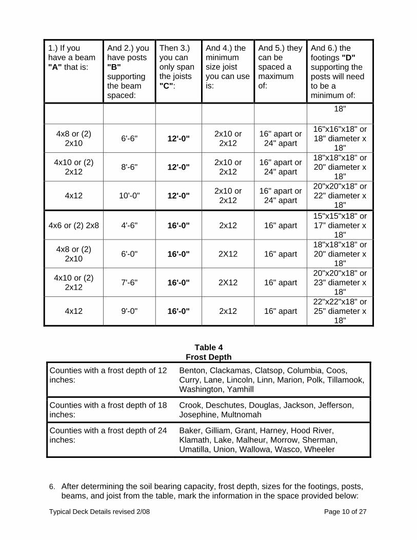
1.) If you have a beam "A" that is:
And 2.) you have posts "B" supporting the beam spaced:
Then 3.) you can only span the joists "C":
And 4.) the minimum size joist you can use is:
And 5.) they can be spaced a maximum of:
And 6.) the footings "D" supporting the posts will need to be a minimum of:
18"
4x8 or (2) 2x10 6'-6" 12'-0" 2x10 or
2x12 16" apart or
24" apart
16"x16"x18" or 18" diameter x
18"
4x10 or (2) 2x12 8'-6" 12'-0" 2x10 or
2x12 16" apart or
24" apart
18"x18"x18" or 20" diameter x
18"
4x12 10'-0" 12'-0" 2x10 or 2x12
16" apart or 24" apart
20"x20"x18" or 22" diameter x
18"
4x6 or (2) 2x8 4'-6" 16'-0" 2x12 16" apart 15"x15"x18" or 17” diameter x
18"
4x8 or (2) 2x10 6'-0" 16'-0" 2X12 16" apart
18"x18"x18" or 20" diameter x
18"
4x10 or (2) 2x12 7'-6" 16'-0" 2X12 16" apart
20"x20"x18" or 23" diameter x
18"
4x12 9'-0" 16'-0" 2x12 16" apart 22"x22"x18" or 25" diameter x
Baker, Gilliam, Grant, Harney, Hood River, Klamath, Lake, Malheur, Morrow, Sherman, Umatilla, Union, Wallowa, Wasco, Wheeler
6. After determining the soil bearing capacity, frost depth, sizes for the footings, posts,
beams, and joist from the table, mark the information in the space provided below:
a. Soil Bearing Value: _______ psf. b. Frost Depth: _______ inches. c. Footing Size: _______ x _______ x _______, spaced _______ apart. d. Post Size: _______ x _______, spaced _______ apart. e. Beam Size: _______ x _______, spaced _______ apart. f. Joist Size: _______ x _______, spaced _______ apart.
7. Determine if you will be connecting to a band board (rim joist), see Figure 5; a concrete wall, see Figure 6; or a sill plate, see Figure 7. Note: This document cannot be used with masonry walls.
8. See Figures 14 to 36 for bracing, connection, built-up beam, footing, guardrail, handrail and stairway details.
POST SIZES
Post sizes are 4x4 minimum for decks six feet or less above the ground and 4x6 for decks over six feet above the ground. Decks with posts over ten feet above the ground cannot be used and require an engineered design. Use a minimum 4x6 post under all beam splices.
LEDGER ATTACHMENT REQUIREMENTS General: There are several methods for attaching a ledger board to the house. How it is attached depends on how the house is constructed and where the ledger will be attached. Ledger board attachments to the existing exterior wall shall be constructed in accordance with Figures 5 through 7. When attachments are made to the existing house band board, it shall be capable of supporting the new deck. If this cannot be verified or conditions at the existing house differ from the details herein, then a free-standing deck is required (See section on Free-Standing Decks.). You must verify the existing conditions in the field prior to applying for a building permit. Compliance with all the requirements herein is critical to ensure the structural stability of your deck. Siding and Flashing: Siding or the exterior finish system must be removed prior to the installation of the ledger board. Flashing is required at any ledger board connection to a wall of wood-framed construction and shall be composed of copper (attached using copper nails), stainless steel, UV-resistant plastic, or galvanized steel coated with 1.85 oz/sf of zinc (G-185 coating).
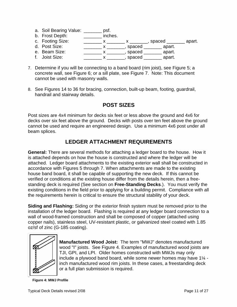
Manufactured Wood Joist: The term "MWJ" denotes manufactured wood "I" joists. See Figure 4. Examples of manufactured wood joists are TJI, GPI, and LPI. Older homes constructed with MWJs may only include a plywood band board, while some newer homes may have 1¼ -inch manufactured wood rim joists. In these cases, a freestanding deck or a full plan submission is required.
Typical Deck Details revised 2/08 Page 11 of 27
Figure 4: MWJ Profile
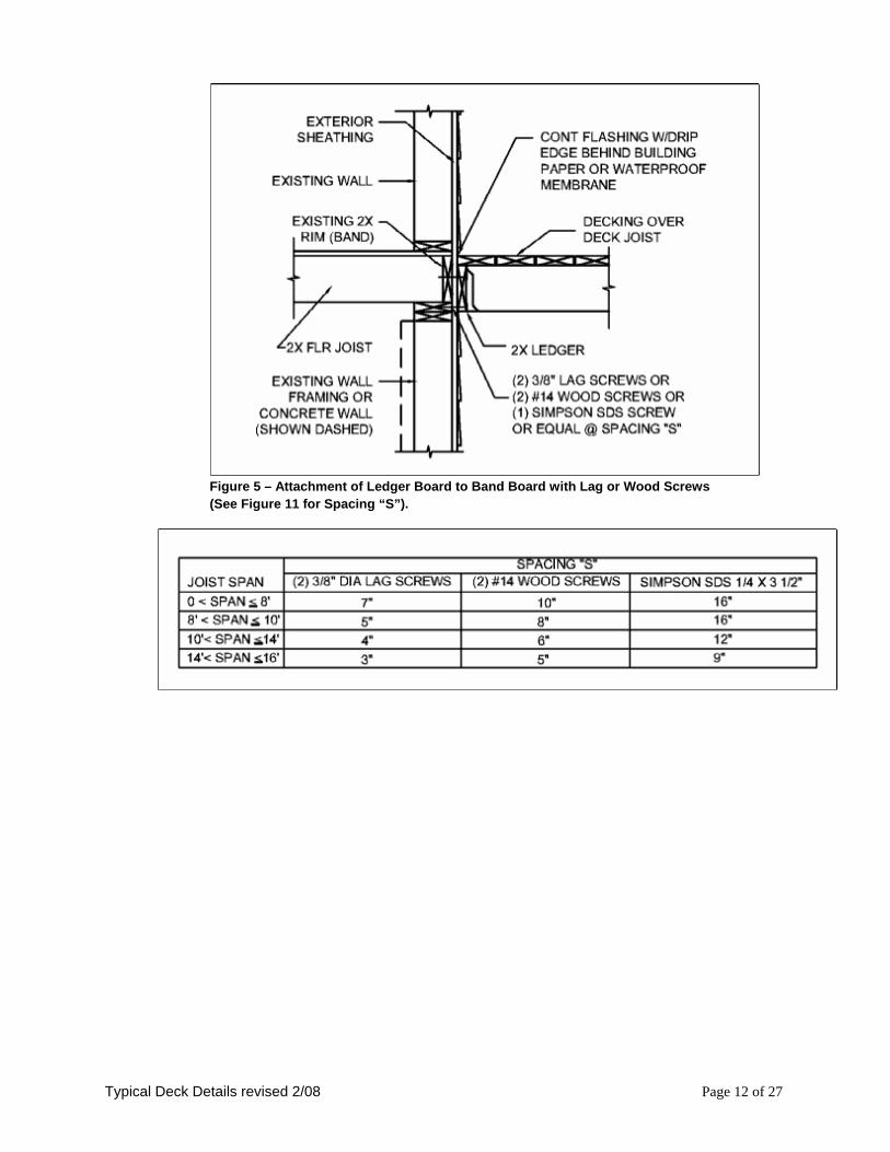
Figure 5 – Attachment of Ledger Board to Band Board with Lag or Wood Screws (See Figure 11 for Spacing “S”).
Typical Deck Details revised 2/08 Page 12 of 27
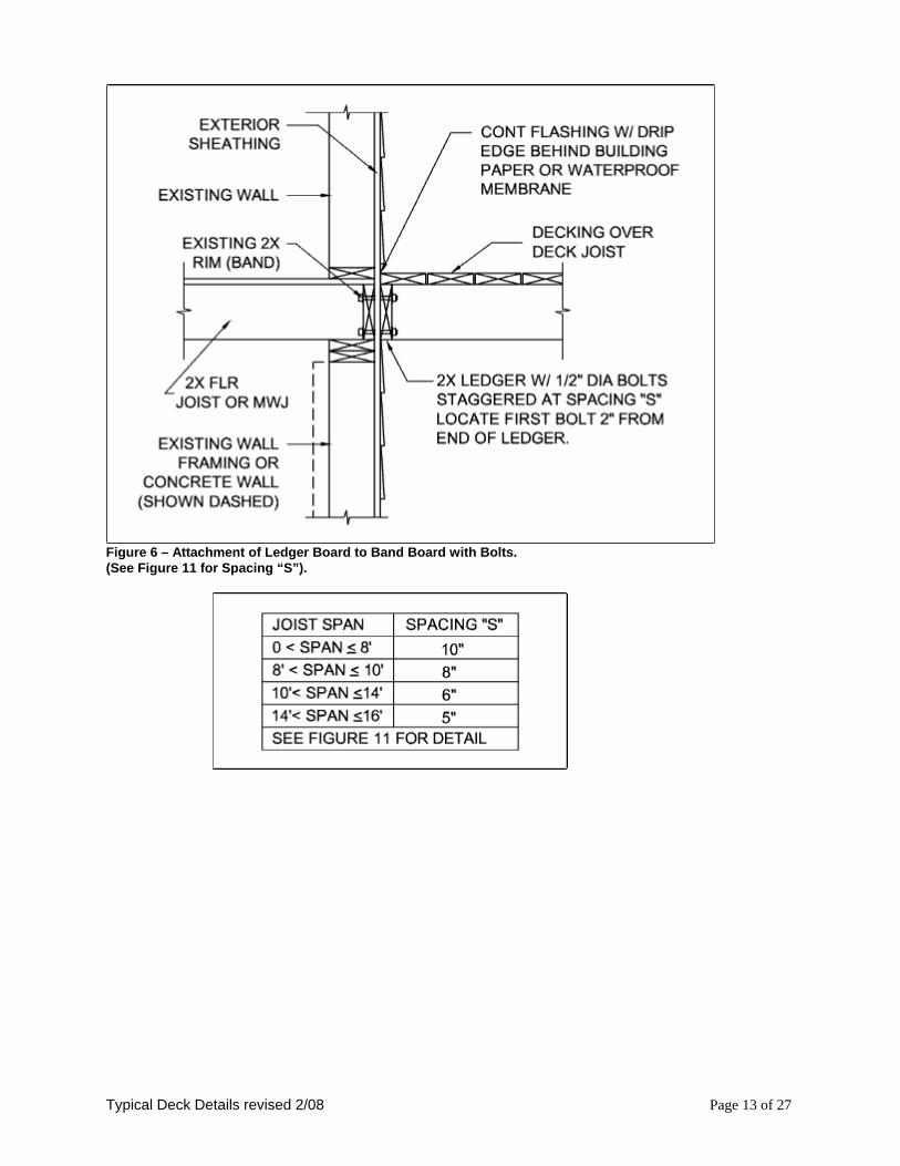
Figure 6 – Attachment of Ledger Board to Band Board with Bolts. (See Figure 11 for Spacing “S”).
Typical Deck Details revised 2/08 Page 13 of 27
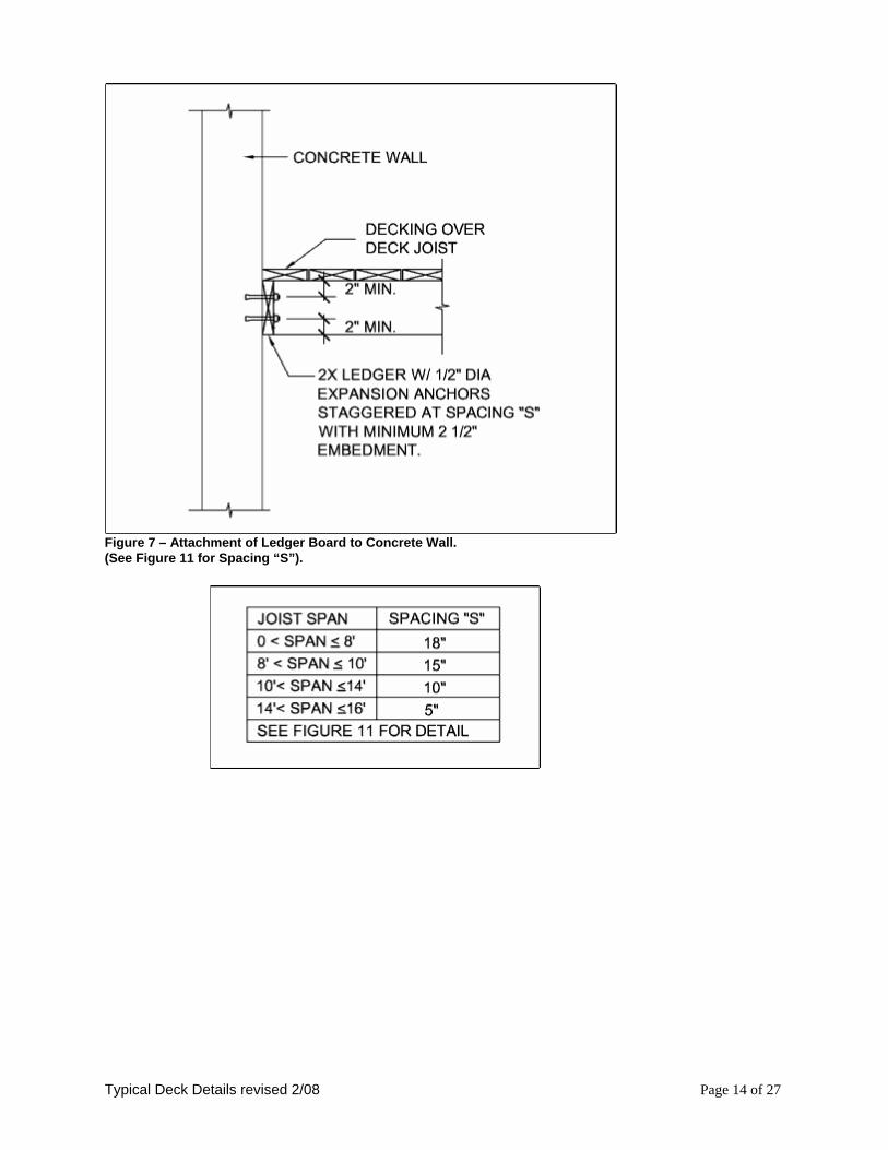
Figure 7 – Attachment of Ledger Board to Concrete Wall. (See Figure 11 for Spacing “S”).
Typical Deck Details revised 2/08 Page 14 of 27
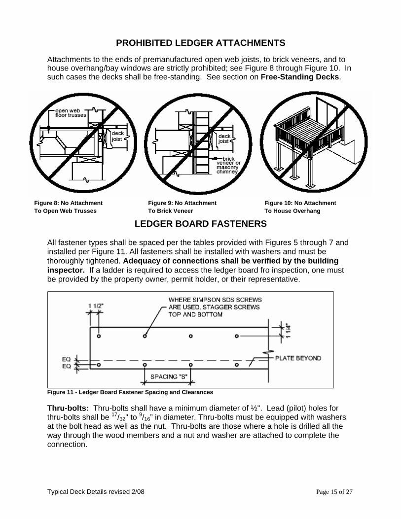
PROHIBITED LEDGER ATTACHMENTS Attachments to the ends of premanufactured open web joists, to brick veneers, and to house overhang/bay windows are strictly prohibited; see Figure 8 through Figure 10. In such cases the decks shall be free-standing. See section on Free-Standing Decks.
Figure 8: No Attachment Figure 9: No Attachment Figure 10: No Attachment To Open Web Trusses To Brick Veneer To House Overhang
LEDGER BOARD FASTENERS All fastener types shall be spaced per the tables provided with Figures 5 through 7 and installed per Figure 11. All fasteners shall be installed with washers and must be thoroughly tightened. Adequacy of connections shall be verified by the building inspector. If a ladder is required to access the ledger board fro inspection, one must be provided by the property owner, permit holder, or their representative.
Figure 11 - Ledger Board Fastener Spacing and Clearances Thru-bolts: Thru-bolts shall have a minimum diameter of ½". Lead (pilot) holes for thru-bolts shall be 17/32" to 9/16” in diameter. Thru-bolts must be equipped with washers at the bolt head as well as the nut. Thru-bolts are those where a hole is drilled all the way through the wood members and a nut and washer are attached to complete the connection.
Typical Deck Details revised 2/08 Page 15 of 27
Expansion (Wedge) Anchors: Use expansion anchors when attaching a ledger board to a concrete wall as shown in Figure 7. Bolt diameters of the anchors shall be a minimum of ½"; in some cases, this may require an anchor size of 5/8". Minimum embedment length shall be 2½". Expansion anchors must have washers. IMPORTANT NOTE: Expansion anchors must be installed as required by the manufacturer’s instructions. This may include cleaning the holes drilled in the concrete to ensure they are free of dirt, debris, and moisture. Improper installation of the anchors can result in catastrophic failure and collapse of the deck. Copies of the manufacturer's installation instructions must be submitted with this handout and permit application. Lag Screws: Lag screws shall have a minimum diameter of 3/8" and shall be hot-dipped galvanized or stainless steel. Lag screws may be used only when the field conditions match those shown in Figure 12. You must verify the existing conditions in the field prior to applying for a building permit and installing lag screws. Compliance with all the requirements herein is critical to ensure the structural stability of your deck. See Figure 12 for lag screw length and shank requirements. All lag screws shall be installed with washers. Lag screws are those where a pilot hole is drilled into the wood members that are to be connected together and the lag is screwed into the hole, a washer is required on the lag head, but no nut and washer is needed on the screw end.
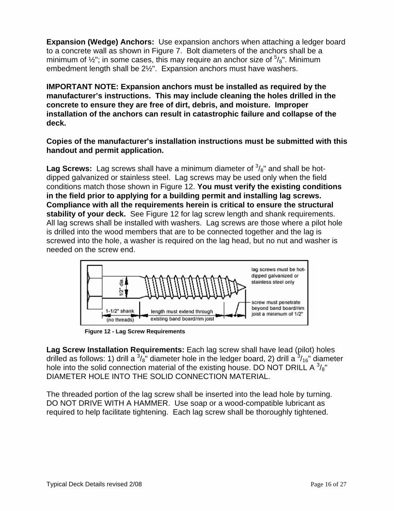
Figure 12 - Lag Screw Requirements
Lag Screw Installation Requirements: Each lag screw shall have lead (pilot) holes drilled as follows: 1) drill a 3/8" diameter hole in the ledger board, 2) drill a 3/16" diameter hole into the solid connection material of the existing house. DO NOT DRILL A 3/8" DIAMETER HOLE INTO THE SOLID CONNECTION MATERIAL. The threaded portion of the lag screw shall be inserted into the lead hole by turning. DO NOT DRIVE WITH A HAMMER. Use soap or a wood-compatible lubricant as required to help facilitate tightening. Each lag screw shall be thoroughly tightened.
Typical Deck Details revised 2/08 Page 16 of 27
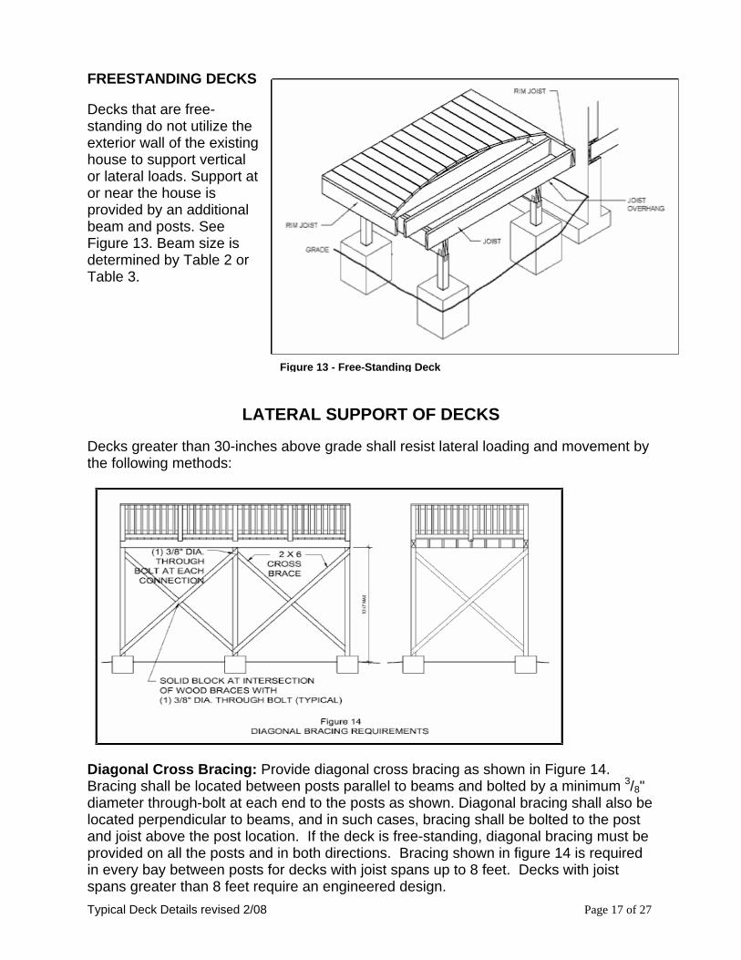
FREESTANDING DECKS
Figure 13 - Free-Standing Deck
Decks that are free-standing do not utilize the exterior wall of the existing house to support vertical or lateral loads. Support at or near the house is provided by an additional beam and posts. See Figure 13. Beam size is determined by Table 2 or Table 3.
LATERAL SUPPORT OF DECKS
Decks greater than 30-inches above grade shall resist lateral loading and movement by the following methods:
Diagonal Cross Bracing: Provide diagonal cross bracing as shown in Figure 14. Bracing shall be located between posts parallel to beams and bolted by a minimum 3/8" diameter through-bolt at each end to the posts as shown. Diagonal bracing shall also be located perpendicular to beams, and in such cases, bracing shall be bolted to the post and joist above the post location. If the deck is free-standing, diagonal bracing must be provided on all the posts and in both directions. Bracing shown in figure 14 is required in every bay between posts for decks with joist spans up to 8 feet. Decks with joist spans greater than 8 feet require an engineered design. Typical Deck Details revised 2/08 Page 17 of 27
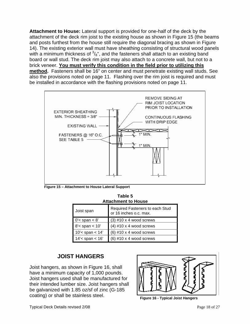
Attachment to House: Lateral support is provided for one-half of the deck by the attachment of the deck rim joist to the existing house as shown in Figure 15 (the beams and posts furthest from the house still require the diagonal bracing as shown in Figure 14). The existing exterior wall must have sheathing consisting of structural wood panels with a minimum thickness of 3/8", and the fasteners shall attach to an existing band board or wall stud. The deck rim joist may also attach to a concrete wall, but not to a brick veneer. You must verify this condition in the field prior to utilizing this method. Fasteners shall be 16" on center and must penetrate existing wall studs. See also the provisions noted on page 11. Flashing over the rim joist is required and must be installed in accordance with the flashing provisions noted on page 11.
Figure 15 – Attachment to House Lateral Support
Table 5
Attachment to House
Joist span Required Fasteners to each Stud or 16 inches o.c. max.
0’< span < 8’ (3) #10 x 4 wood screws 8’< span < 10’ (4) #10 x 4 wood screws 10’< span < 14’ (6) #10 x 4 wood screws 14’< span < 16’ (6) #10 x 4 wood screws
JOIST HANGERS
Figure 16 - Typical Joist Hangers
Joist hangers, as shown in Figure 16, shall have a minimum capacity of 1,000 pounds. Joist hangers used shall be manufactured for their intended lumber size. Joist hangers shall be galvanized with 1.85 oz/sf of zinc (G-185 coating) or shall be stainless steel. Typical Deck Details revised 2/08 Page 18 of 27
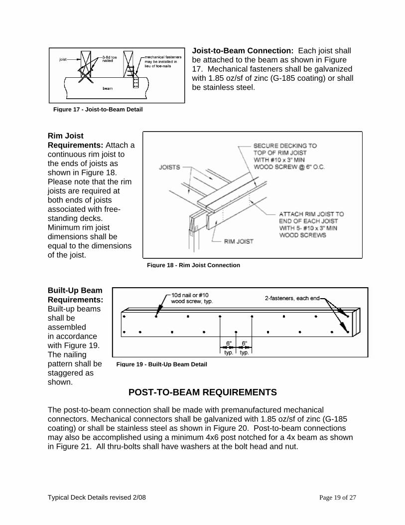
Joist-to-Beam Connection: Each joist shall be attached to the beam as shown in Figure 17. Mechanical fasteners shall be galvanized with 1.85 oz/sf of zinc (G-185 coating) or shall be stainless steel.
Figure 17 - Joist-to-Beam Detail
Rim Joist Requirements: Attach a continuous rim joist to the ends of joists as shown in Figure 18. Please note that the rim joists are required at both ends of joists associated with free-standing decks. Minimum rim joist dimensions shall be equal to the dimensions of the joist.
Figure 18 - Rim Joist Connection Built-Up Beam
Figure 19 - Built-Up Beam Detail
Requirements: Built-up beams shall be assembled in accordance with Figure 19. The nailing pattern shall be staggered as shown.
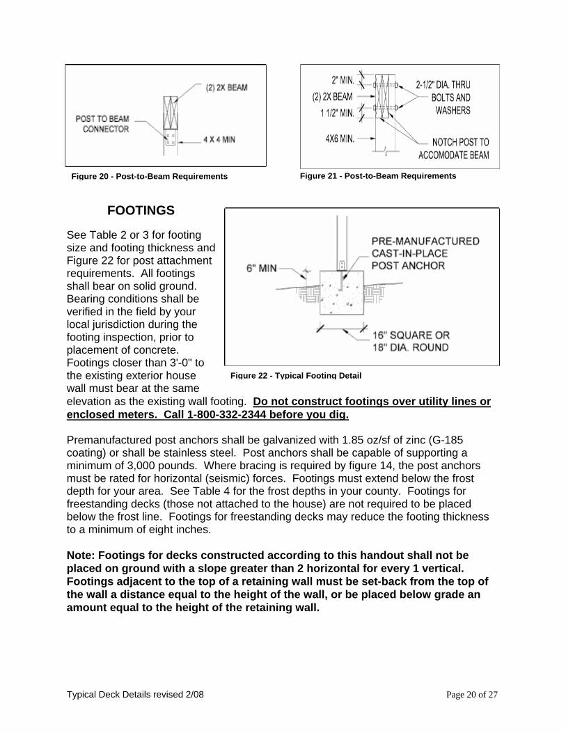
POST-TO-BEAM REQUIREMENTS The post-to-beam connection shall be made with premanufactured mechanical connectors. Mechanical connectors shall be galvanized with 1.85 oz/sf of zinc (G-185 coating) or shall be stainless steel as shown in Figure 20. Post-to-beam connections may also be accomplished using a minimum 4x6 post notched for a 4x beam as shown in Figure 21. All thru-bolts shall have washers at the bolt head and nut.
See Table 2 or 3 for footing size and footing thickness and Figure 22 for post attachment requirements. All footings shall bear on solid ground. Bearing conditions shall be verified in the field by your local jurisdiction during the footing inspection, prior to placement of concrete. Footings closer than 3'-0" to the existing exterior house wall must bear at the same elevation as the existing wall footing. Do not construct footings over utility lines or enclosed meters. Call 1-800-332-2344 before you dig.
Figure 22 - Typical Footing Detail
Premanufactured post anchors shall be galvanized with 1.85 oz/sf of zinc (G-185 coating) or shall be stainless steel. Post anchors shall be capable of supporting a minimum of 3,000 pounds. Where bracing is required by figure 14, the post anchors must be rated for horizontal (seismic) forces. Footings must extend below the frost depth for your area. See Table 4 for the frost depths in your county. Footings for freestanding decks (those not attached to the house) are not required to be placed below the frost line. Footings for freestanding decks may reduce the footing thickness to a minimum of eight inches. Note: Footings for decks constructed according to this handout shall not be placed on ground with a slope greater than 2 horizontal for every 1 vertical. Footings adjacent to the top of a retaining wall must be set-back from the top of the wall a distance equal to the height of the wall, or be placed below grade an amount equal to the height of the retaining wall.
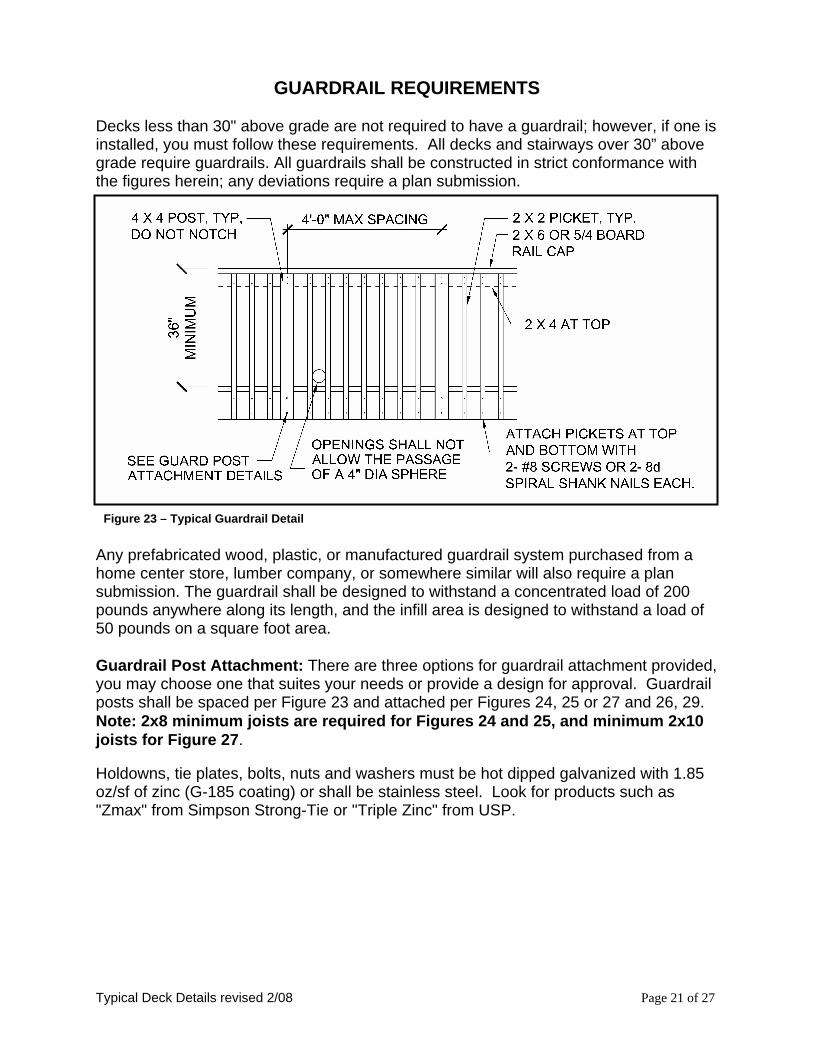
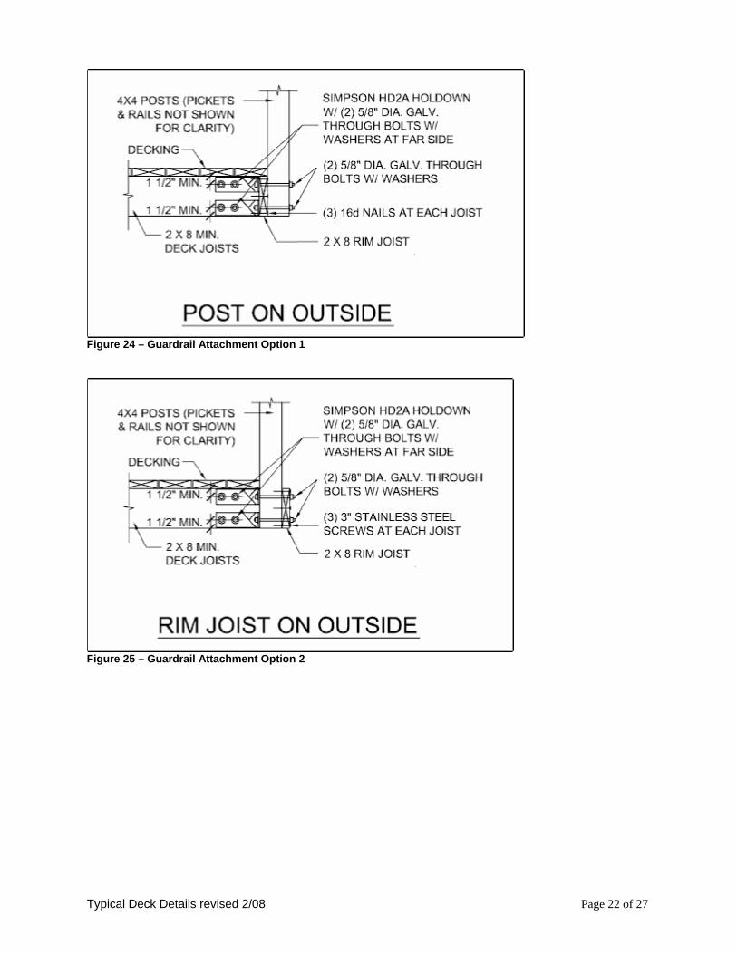
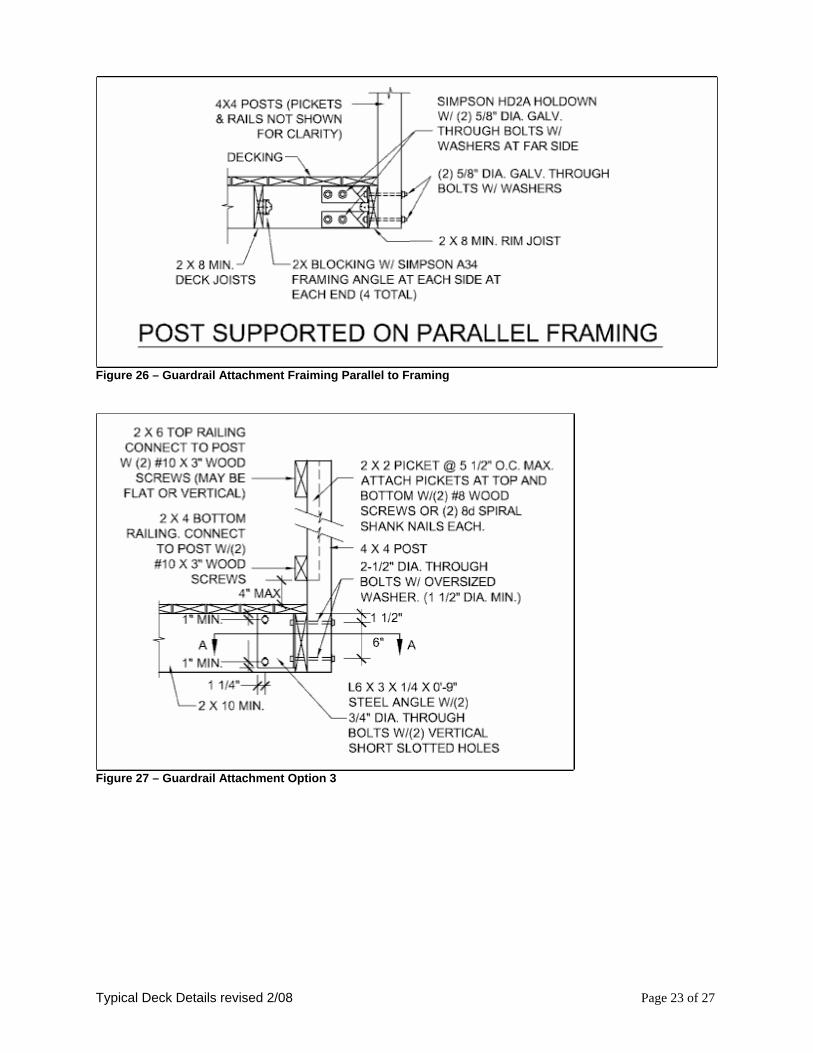
GUARDRAIL REQUIREMENTS Decks less than 30" above grade are not required to have a guardrail; however, if one is installed, you must follow these requirements. All decks and stairways over 30” above grade require guardrails. All guardrails shall be constructed in strict conformance with the figures herein; any deviations require a plan submission. Figure 23 – Typical Guardrail Detail Any prefabricated wood, plastic, or manufactured guardrail system purchased from a home center store, lumber company, or somewhere similar will also require a plan submission. The guardrail shall be designed to withstand a concentrated load of 200 pounds anywhere along its length, and the infill area is designed to withstand a load of 50 pounds on a square foot area. Guardrail Post Attachment: There are three options for guardrail attachment provided, you may choose one that suites your needs or provide a design for approval. Guardrail posts shall be spaced per Figure 23 and attached per Figures 24, 25 or 27 and 26, 29. Note: 2x8 minimum joists are required for Figures 24 and 25, and minimum 2x10 joists for Figure 27. Holdowns, tie plates, bolts, nuts and washers must be hot dipped galvanized with 1.85 oz/sf of zinc (G-185 coating) or shall be stainless steel. Look for products such as "Zmax" from Simpson Strong-Tie or "Triple Zinc" from USP.
Typical Deck Details revised 2/08 Page 21 of 27
Figure 24 – Guardrail Attachment Option 1
Figure 25 – Guardrail Attachment Option 2
Typical Deck Details revised 2/08 Page 22 of 27
Figure 26 – Guardrail Attachment Fraiming Parallel to Framing
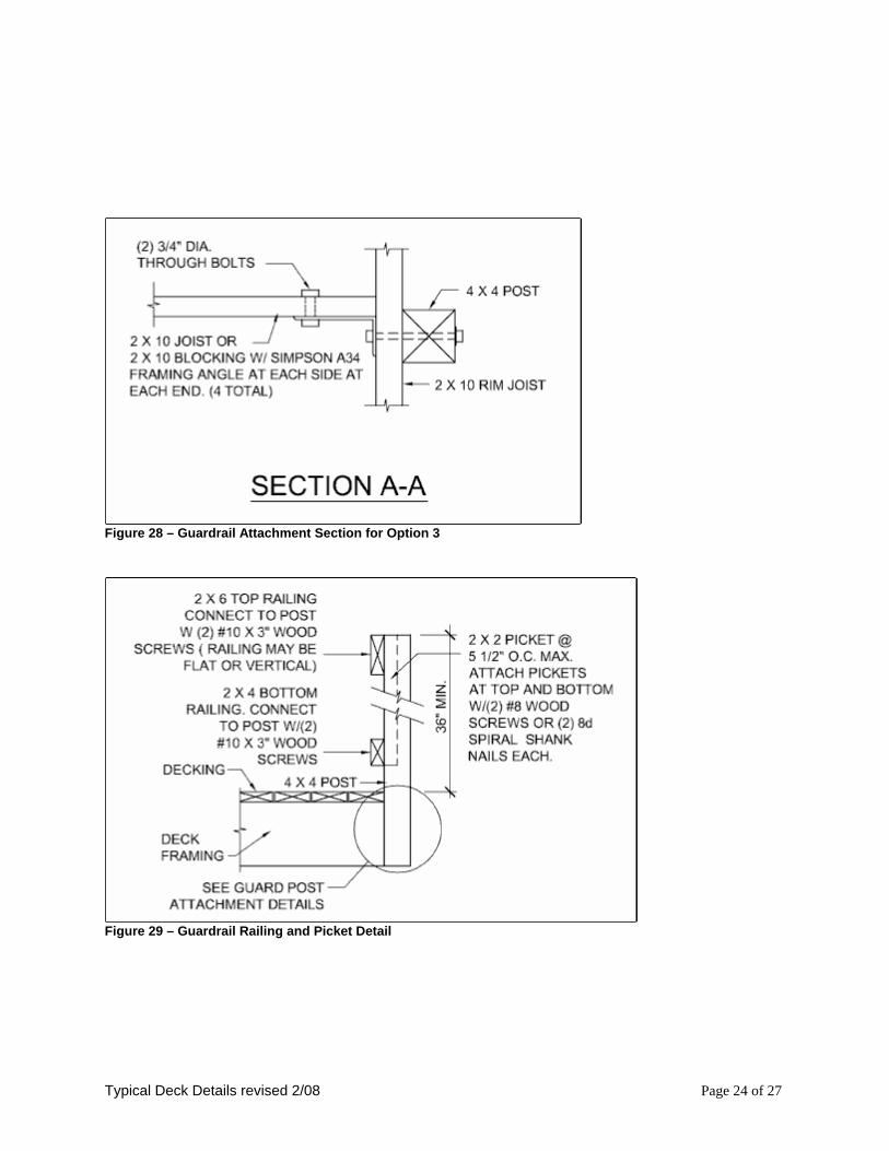
Figure 28 – Guardrail Attachment Section for Option 3
Figure 29 – Guardrail Railing and Picket Detail
Typical Deck Details revised 2/08 Page 24 of 27
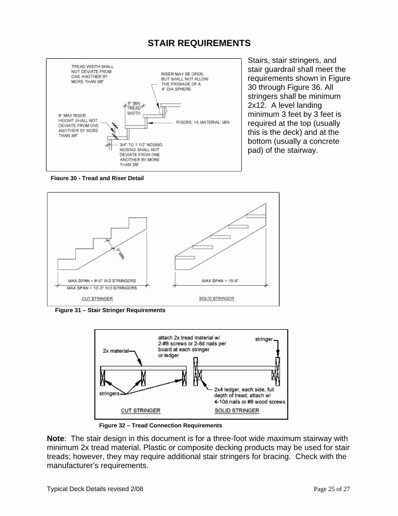
STAIR REQUIREMENTS
Stairs, stair stringers, and stair guardrail shall meet the requirements shown in Figure 30 through Figure 36. All stringers shall be minimum 2x12. A level landing minimum 3 feet by 3 feet is required at the top (usually this is the deck) and at the bottom (usually a concrete pad) of the stairway.
Figure 30 - Tread and Riser Detail
Figure 31 – Stair Stringer Requirements
Figure 32 – Tread Connection Requirements
Note: The stair design in this document is for a three-foot wide maximum stairway with minimum 2x tread material. Plastic or composite decking products may be used for stair treads; however, they may require additional stair stringers for bracing. Check with the manufacturer’s requirements.
Typical Deck Details revised 2/08 Page 25 of 27
Typical Deck Details revised 2/08 Page 26 of 27
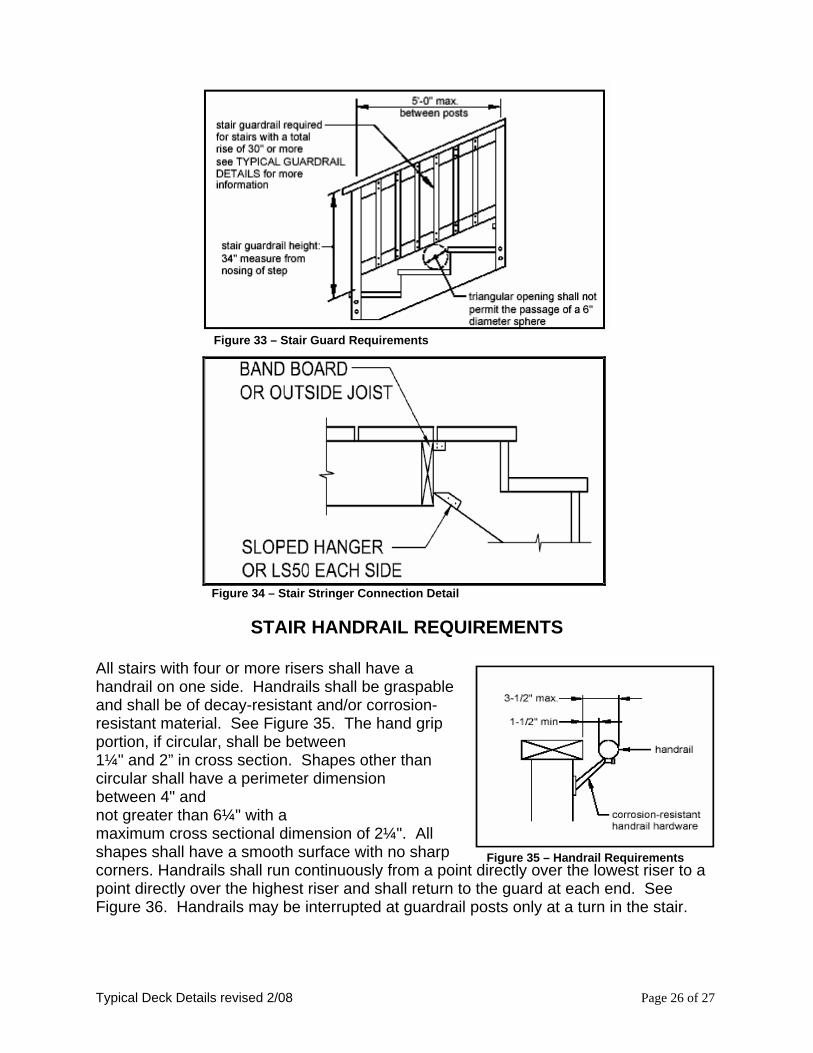
Figure 35 – Handrail Requirements
Figure 33 – Stair Guard Requirements
Figure 34 – Stair Stringer Connection Detail
STAIR HANDRAIL REQUIREMENTS
All stairs with four or more risers shall have a handrail on one side. Handrails shall be graspable and shall be of decay-resistant and/or corrosion-resistant material. See Figure 35. The hand grip portion, if circular, shall be between 1¼" and 2” in cross section. Shapes other than circular shall have a perimeter dimension between 4" and not greater than 6¼" with a maximum cross sectional dimension of 2¼". All shapes shall have a smooth surface with no sharp corners. Handrails shall run continuously from a point directly over the lowest riser to a point directly over the highest riser and shall return to the guard at each end. See Figure 36. Handrails may be interrupted at guardrail posts only at a turn in the stair.
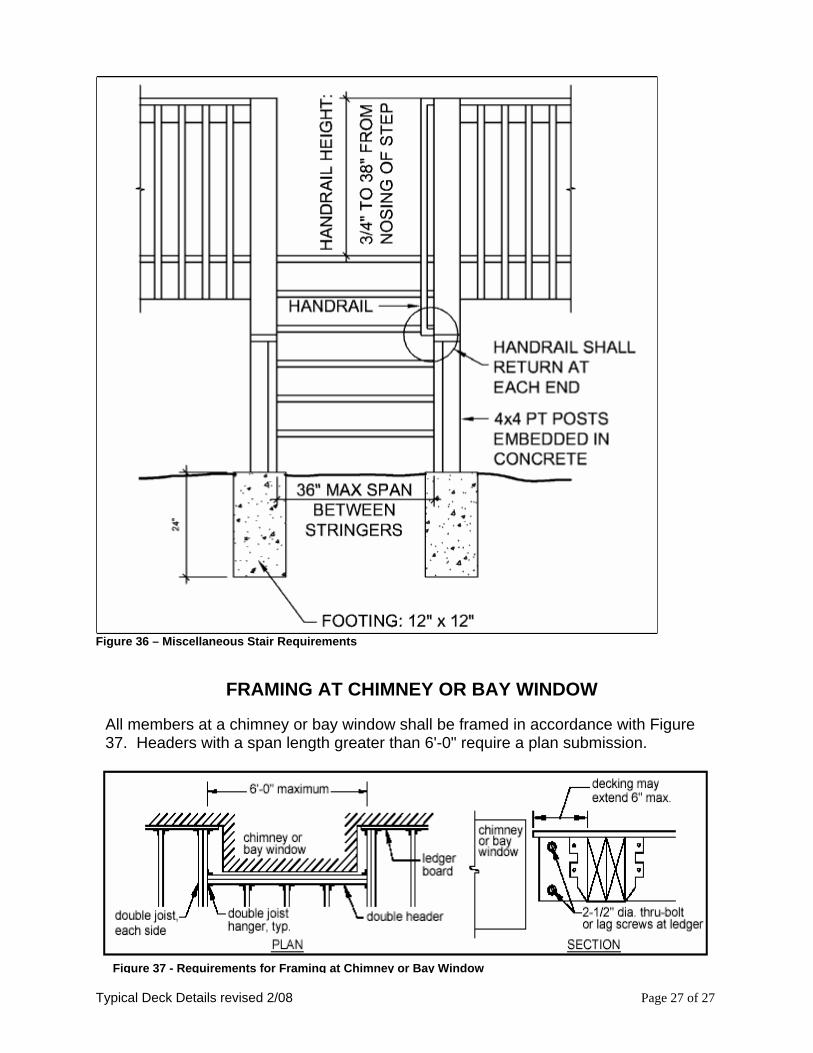
Figure 36 – Miscellaneous Stair Requirements
FRAMING AT CHIMNEY OR BAY WINDOW All members at a chimney or bay window shall be framed in accordance with Figure 37. Headers with a span length greater than 6'-0" require a plan submission.
Figure 37 - Requirements for Framing at Chimney or Bay Window