ANOTHER G & G ELECTRIC AND PLUMBING DISTRIBUTORS, INC. INFORMATION SHEET COPYRIGHT 1989 37 These “How-To-Do-It” sheets have been reviewed in June 2007 by a professional Engineer. If you find a problem, please notify G & G Electric & Plumbing at 1900 78 th Street, Ste. 101, Vancouver, Washington 98665 TYPICAL SUBMERSIBLE PUMP INSTALLATION 1. We recommend the captive-air style pressure tank. It has significantly higher drawdown than a standard pressure tank and eliminates water logging problems. The air level in the tank should be 2 lbs. less than pressure switch turn-on level. For a 30-50 switch, this would be 28 lbs. of air with the tank dry. 2. Use a pressure switch featuring a low-pressure cut-out for wells of low or unknown production. 3. WARNING! A pressure relief valve is required by plumbing code and should be large enough to relieve the maximum GPM of the system’s design. 4. WARNING! Piping inside buildings must be of an approved type, generally metal. Schedule 40 PVC is recommended for running in trenches. PEX or CPVC non-metallic piping may be approved – check with local code enforcement agency.
Transcript
ANOTHERG & G ELECTRIC AND PLUMBING DISTRIBUTORS, INC.INFORMATION SHEETCOPYRIGHT 1989
37
These “How-To-Do-It” sheets have been reviewed in June 2007 by a professional Engineer. If you find a problem, please notifyG & G Electric & Plumbing at 1900 78th Street, Ste. 101, Vancouver, Washington 98665
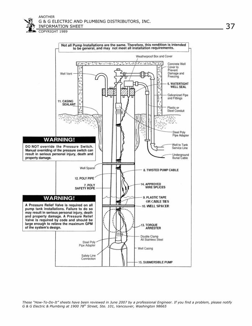
TYPICAL SUBMERSIBLE PUMP INSTALLATION
1. We recommend the captive-air style pressure tank. It has significantly higherdrawdown than a standard pressure tank and eliminates water logging problems.The air level in the tank should be 2 lbs. less than pressure switch turn-on level.For a 30-50 switch, this would be 28 lbs. of air with the tank dry.
2. Use a pressure switch featuring a low-pressure cut-out for wells of low orunknown production.
3. WARNING! A pressure relief valve is required by plumbing code and should belarge enough to relieve the maximum GPM of the system’s design.
4. WARNING! Piping inside buildings must be of an approved type, generallymetal. Schedule 40 PVC is recommended for running in trenches. PEX or CPVCnon-metallic piping may be approved – check with local code enforcementagency.
ANOTHERG & G ELECTRIC AND PLUMBING DISTRIBUTORS, INC.INFORMATION SHEETCOPYRIGHT 1989
37
These “How-To-Do-It” sheets have been reviewed in June 2007 by a professional Engineer. If you find a problem, please notifyG & G Electric & Plumbing at 1900 78th Street, Ste. 101, Vancouver, Washington 98665
5. Codes require the well head to be above ground. Thewell seal caps the casing while providing ports for thepipe, wire and venting.
6. A poly rope is used as a safety line for pumps installedwithin its weight limits. Stainless steel cable should beused when weight exceeds poly rope limits.
7. Some areas permit use of UF wire to pump. Othersrequire pump cable. Check before installing UF-typewire.
8. Use nylon cable ties or electrical tape above and beloweach well spacer to secure wire to pipe and keep thespacer in place.
9. If using poly pipe, locate well spacers 10’ apart to centerpipe and keep wires from chafing on the well casing.
10. Casing sealant installed by driller. Prevents surface waterfrom seeping around casing into potable water.
11. Threaded and coupled galvanized pipe should be used onextremely deep wells. Threaded schedule 80 PVC and aheavy grade poly pipe are also available and are muchlighter and easier to work with.
12. Position a torque arrestor directly above the top of thepump. This will center the pump in the well and keep thepipe from twisting due to torque created by the pumpmotor.
13. IMPORTANT! Wire splices should be staggered, securelycrimped and weatherproof. Heat shrink splice kits have asealant that makes the joint completely waterproof.
14. Pump should be suspended some distance off the bottomespecially when a sand condition exists. Check withdriller for proper height for pump.
IMPORTANT! When pump is first started, it should be leftrunning until test samples clear up and are completely free ofsand.
Plastic orSteel Conduit
Steel PolyPipe Adapter
Safety LineConnection
Double ClampStainless Steel
Well Casing
ANOTHERG & G ELECTRIC AND PLUMBING DISTRIBUTORS, INC.INFORMATION SHEETCOPYRIGHT 1989
37
These “How-To-Do-It” sheets have been reviewed in June 2007 by a professional Engineer. If you find a problem, please notifyG & G Electric & Plumbing at 1900 78th Street, Ste. 101, Vancouver, Washington 98665
ANOTHERG & G ELECTRIC AND PLUMBING DISTRIBUTORS, INC.INFORMATION SHEETCOPYRIGHT 1989
37
These “How-To-Do-It” sheets have been reviewed in June 2007 by a professional Engineer. If you find a problem, please notifyG & G Electric & Plumbing at 1900 78th Street, Ste. 101, Vancouver, Washington 98665