+ All Categories
Home > Documents > UAV Consumable Replenishment: Design Concepts for...

UAV Consumable Replenishment: Design Concepts for...

Date post: 22-Apr-2018
Category:
Upload: truongdieu
View: 214 times
Download: 2 times
Share this document with a friend
26
1 UAV Consumable Replenishment: Design Concepts for Automated Service Stations Paulo Kemper F. 1 ∙ Koji A.O. Suzuki 2 ∙ James R. Morrison 3* Abstract A key requirement for the complete autonomy of an unmanned aerial vehicle (UAV) is the replenishment of its energy source and other consumables. Such processes are typically overseen and conducted by a human operator, may be time consuming and effectively reduce the operating range of the system. To satisfy the requirements of UAV customers such as military surveillance networks, that seek faster, broader and more fully autonomous systems, and hobbyists, who seek to avoid the hassle associated with changing the fuel source, we develop automated energy recharging systems. Focusing on battery operated remote control helicopters, we employ the Axiomatic Design methodology to develop design concepts of platforms to act as automatic service stations. We propose three station designs for refilling platforms and one concept for battery exchange platforms. In addition, we analyze the economic feasibility of automatic consumable replenishment stations, consider two types of station (container refilling and container exchange) and discuss the application of these systems. Refilling platforms better suit low coverage unmanned aerial systems (UAS) while exchange stations allow high coverage with fewer UAVs. Keywords: Unmanned aerial vehicles, automated consumable replenishment, service stations, Axiomatic Design, enabling technologies, autonomy. ___________________ 1 Department of Electrical Engineering, KAIST, Daejeon, Republic of Korea 2 Department of Mechanical Engineering, KAIST, Daejeon, Republic of Korea 3 Department of Industrial and Systems Engineering, KAIST, Daejeon, Republic of Korea *Corresponding author. James R. Morrison. E-mail: [email protected]
Transcript

1

UAV Consumable Replenishment: Design Concepts for

Automated Service Stations Paulo Kemper F.1 ∙ Koji A.O. Suzuki2 ∙ James R. Morrison3*

Abstract

A key requirement for the complete autonomy of an unmanned aerial vehicle (UAV) is the

replenishment of its energy source and other consumables. Such processes are typically overseen

and conducted by a human operator, may be time consuming and effectively reduce the operating

range of the system. To satisfy the requirements of UAV customers such as military surveillance

networks, that seek faster, broader and more fully autonomous systems, and hobbyists, who seek

to avoid the hassle associated with changing the fuel source, we develop automated energy

recharging systems. Focusing on battery operated remote control helicopters, we employ the

Axiomatic Design methodology to develop design concepts of platforms to act as automatic

service stations. We propose three station designs for refilling platforms and one concept for

battery exchange platforms. In addition, we analyze the economic feasibility of automatic

consumable replenishment stations, consider two types of station (container refilling and

container exchange) and discuss the application of these systems. Refilling platforms better suit

low coverage unmanned aerial systems (UAS) while exchange stations allow high coverage with

fewer UAVs.

Keywords: Unmanned aerial vehicles, automated consumable replenishment, service stations,

Axiomatic Design, enabling technologies, autonomy.

___________________ 1Department of Electrical Engineering, KAIST, Daejeon, Republic of Korea

2Department of Mechanical Engineering, KAIST, Daejeon, Republic of Korea

3Department of Industrial and Systems Engineering, KAIST, Daejeon, Republic of Korea

*Corresponding author. James R. Morrison. E-mail: [email protected]

2

1 Introduction

Much research has been conducted and is ongoing to develop unmanned aerial vehicle (UAV)

systems with increasing levels of autonomy. Typically, autonomy is interpreted as requiring

minimal human intervention from take-off to landing. However, complete autonomy requires

autonomous operation on the ground. We develop automatic service stations to replenish

consumables after landing and provide this ground based autonomy. The automation of ground

tasks for UAVs has not yet been extensively developed.

While it is unlikely that all ground based activities can be automated, the replenishment

of consumable reservoirs (i.e., pesticides, seeds or ammunition) or energy sources (i.e., a battery

or a fuel tank) can be targeted for automation. The benefits of such automation are similar to

those of automation in general; examples include the savings of human effort, effective increases

in UAV operation time and, for military applications, reduced risk to human life. For example,

when conducting UAV research to test flight algorithms, humans could be relieved of support

activities so that they may focus on conducting the tests. Note that, as is the case for autonomous

flight, which still requires human oversight and mission direction, some ground based activities

(e.g., maintenance) will require human intervention. Some tasks, such as disassembling the UAV

for cleaning or substitution of broken parts, are simply beyond the capabilities of modern

automation.

The goal of this paper is to design, analyze and economically evaluate consumable

replenishment systems for UAVs. As there are many possible solutions, we focus specifically on

the energy replenishment problem in battery operated rotor UAVs, such as radio or IR controlled

mini-helicopters. Many of the ideas will be applicable to UAV helicopters with any consumable. To

a lesser extent, some of the concepts can be extended to UAV airplanes. In addition to developing

designs, we attempt to answer the following questions. How many UAVs, energy sources (e.g.,

batteries), chargers and service stations are required to provide a desired level of UAV coverage?

Are certain kinds of service stations economically preferable?

While there have been few studies on service stations for UAVs, there have been

numerous efforts to develop recharge platforms for ground based robots (c.f., [1-7]). Service

stations are popular for battery operated commercial robots such as the home vacuum robot

Roomba [8]. In [9], a battery exchange system for land based robots was developed and tested.

The focus of most such research is largely on the control issues associated with identifying when

energy is required and locating the service platform. One distinction between service stations for

ground based robots and UAVs is that UAVs may be able to more readily exploit gravity to aid in

establishing connection between the station and the UAV.

The first and to our knowledge only previous development of a recharge platform for an

autonomous UAV was described in [10]. The implementation was conducted at the MIT

Aerospace Controls Laboratory and included autonomous landing and recharge for a quad rotor

helicopter UAV using a square landing and recharge service station; see [11] and [12]. There, the

UAV control algorithms well position the UAV for landing on the service station and there may be

a terminal identification algorithm required to identify which battery lead has been attached to

each of the four service station terminals. There are some other related efforts. Numerous

studies have been conducted to develop control algorithms enabling fixed wing UAVs to land

vertically on a perch or wall, for example [13] and [14]. In [15], microspines were designed to

allow a small fixed wing UAV to land vertically on a brick wall. These do not consider the

subsequent need for consumable replenishment, but landing on a service station is a requirement

for our systems. There does not appear to be any existing work on battery exchange systems for

UAVs.

Our solution method lies in two directions. First, we study the economic feasibility of two

competing design concepts at a high level based on the target number of UAVs in flight at a given

time, or coverage. One possible approach is to recharge batteries while the UAV waits on the

platform with a low cost, low coverage service station. A second approach is to deploy a more

elaborate solution that exchanges the drained battery for a fully charged one. A recharging

station that holds the UAV during the recharge will require more UAVs and service stations to

provide the same level of coverage. Our economic analysis links the cost with the desired

coverage of the system. While the results depend on the costs of the components, in general we

find that a refilling system may be more economical for low target coverage. Given that both of

these design concepts are applicable to different coverage levels, we will investigate them both.

3

Our emphasis is on battery charging service systems.

We next employ the Axiomatic Design methodology to develop recharge service

platform designs for UAVs. Our focus is on the platform itself rather than the methods associated

with directing the UAV to the platform. Numerous design concepts to address the problem are

developed and analyzed with Axiomatic Design. Key ideas/features are modularity, orientation

independence, terminal connections and matching, cost effectiveness and complexity. These

designs and ideas are the main contribution of the paper.

The paper is organized as follows. In Section 2, we describe the coverage problem and

conduct related economic analysis. Section 3 provides a brief introduction to Axiomatic Design

and develops the highest level functional requirements (FRs) and design parameters (DPs) for the

problem. In Section 4, we develop numerous designs, including the Concentric Circles and

Honeycomb designs, to provide the required functions for energy refill systems. In Section 5, we

provide commentary on the cost and complexity of the various designs. A conceptual design for

the energy exchange approach is briefly discussed in Section 6. Concluding remarks are provided

in Section 7.

2 UAV Coverage and Economic Comparison

To determine whether it is more economical to deploy a collection of service stations that refill

vehicles while they rest on a station (as in [10-12]) or simply exchange the energy source, one

must specify ������� ,the target level of UAV coverage to be provided by the system. Precisely, let

�������be the desired long term average number of UAVs in flight at each moment. Starting from

this parameter, we obtain bounds on the number of components to accomplish the coverage. We

study battery refilling systems, battery exchange systems and conduct an economic comparison.

For simplicity, we assume that all UAVs, batteries and battery chargers are identical.

The distinction between refilling and exchange service stations is that the consumable

reservoir (battery) remains with the UAV at all times in a refilling system. For the exchange, the

UAV swaps out the used battery at the service station for a completely charged one; the UAV is

then free to continue flight while the old battery is recharged at the station. Note that the same

ideas will hold for the replenishment of other consumables.

We develop lower bounds on the number of components (e.g., UAVs, batteries) required

to achieve a target ������� based on the resource utilization required to meet the goal. In practice,

more components may be required to achieve the coverage since contention for the charging

resources may occur using only the utilization based minimum number of components. Our goal,

however, is not to develop UAV and resource schedules; this can be done with a mathematical

programming scheduling formulation. Rather, it is our purpose to provide justification that there

are some parameter regimes in which the refill service station is preferable and some in which

the exchange service stations are preferable. We consider the lower bounds sufficient for this

purpose.

2.1 Components for a Refilling Service Station

Let TF denote the flight time of a UAV starting with a fully charged battery and let TC denote the

battery charging time (including possibly any time for overhead activities associated with station

docking). The parameter CUAV = TF/(TF+TC) is thus the maximum proportion of time a UAV can be in

flight. From this, provided there are sufficient charging resources, the maximum achievable long

term average number of UAVs in flight at a time is ����� = ��� ∙ ��� ., where ��� is the

number of UAVs in the system. The number of UAVs required ��� � to provide the desired

system coverage ������� thus satisfies

��� � ≥ �������� ��� ⁄ �,

(1)

where �∙� is the smallest integer greater or equal to the argument.

If we indeed employ ��� � UAVs, due to the �∙� function, ����� ≥ �������. Thus, the

system need not operate each UAV full time and an idle period can be inserted into the operation

cycle of each UAV to decrease the system coverage to�������. For every � + �� units of time, the

duration of this idle period is

4

����� = ��� + �� ∙ �� !"# ∙ !"$%$&'&

− 1*,

(2)

where we assume that the system resources are indeed sufficient. To ensure that the platform

and its charger are available to serve other UAVs, we assume that the UAV departs from the

platform for the duration of the idle period (retiring to a location immediately neighbouring the

platform and requiring neither time nor charge to do so).

Let TS = TF + TC + TIDLE denote the duration of time for a UAV to operate until its energy

source is completely depleted, then recharge and subsequently lay idle prior to resuming flight.

As the proportion of time in a duration TS that each UAV is charging is (TC/TS), the number of

service station platforms required �+� satisfies

�+� ≥ ,��� � ∙ -�.�$/0.

(3)

Assuming that the battery charger is in use the entire time the UAV is docked at that

platform, the required number of chargers ���� = �+�. Since each battery remains with its UAV,

the number of required batteries is

�1��� = ��� � .

(4)

These are all of the components for a refill (i.e., charging) service station system.

Example 1: Number of Components. Consider a battery operated single rotor UAV with TF = 20

min and TC = 50 min. Our desired 2343565 = 7. 9 UAVs/unit time. Since CUAV = 2/7, :;<5= =:><?= ≥ �7. 9 �7/A�⁄ � = �BC/CD� = CD. With a fleet of ten UAVs, the maximum achievable

system coverage is 2343<2E = 2><? ∙ :><? = 7DA = 79A. Note that this is greater than the target

coverage. The idle time per flight and recharge is 5FGHI = �JD + 7D� ∙ ��CD/B. C� − C� =9. B7K min. Using equation (4), the bound on the number of service stations and chargers is

:26== = :L= ≥ �CD ∙ �JD/A9. B7K�� = A.

2.2 Components for an Exchange Service Station

Consider a system of UAVs and battery exchange service stations with �������. Given TF, TC, as

before, and TR the constant time that a UAV must spend at a service station to replace (exchange)

its battery, let CUAV = TF/(TF+TR). The bound on ��� � is as in inequality (1). As above, let TS = TF +

TR + TIDLE, where TIDLE is given as

����� = ��� + ��� ∙ �� !"# ∙ !"$%$&'&

− 1*.

(5)

The distinction between equations (2) and (5) is that UAVs in exchange systems spend

only TR units of time at the station instead of TC. Assuming that we insert an idle time of duration

TIDLE into each UAV operation cycle, the number of service station platforms required is bound as

�+� ≥ ,��� � ∙ -�#�$/0.

(6)

Unlike the refill service stations, the exchange station must have a supply of charging

batteries from which to draw. Assume that one battery is associated with each UAV at all times.

Also, assume that during the transfer of a battery from service station to the UAV, neither the

empty battery nor the fully charged one are in contact with a charger. That is, during the

exchange operation, both batteries involved are neither receiving nor providing energy. For every

battery in the system, and assuming full flight duration for each UAV trip, the minimum time from

the completion of battery loading to a UAV to the completion of loading of that battery on the

subsequent UAV is TC + 2TR + TIDLE + TF. Of this duration, the minimum time that a battery spends

with the platform is TC + 2TR. If we do not assume full flight duration for each UAV, there will be

5

additional resources required due to a relatively larger portion of time spent replacing batteries.

The lower bound below on batteries will thus still hold.

Assuming every UAV flight is for the full duration TF, in each duration TS, every UAV will

be scheduled to initiate a flight once. Thus, the number of batteries that must be fully charged

each cycle equals ��� � . To supply one battery in a cycle TS requires at least (TC + 2TR)/ TS

batteries. Thus, a lower bound on �1��� , the number of batteries required to achieve the target

coverage, is

�1��� ≥ ��� � + ,��� � ∙ -�.MN�#�$ /0.

(7)

To support the charging of these batteries, we require ���� chargers. Since a charger is

not required during the exchange, a bound on ���� is

���� ≥ ,��� � ∙ -�.�$/0.

(8)

Example 2: Required components for an exchange service system. Consider a battery operated

single rotor UAV with TF = 20 min, TR = 1 min and TC = 50 min. Our desired 2343565 = 7. 9

UAVs/unit time. Since CUAV = 20/21, :><?= ≥ �7. 9/�7D/7C�� = K. With this complement of

UAVs, the maximum achievable system coverage is 2343<2E = 2><? ∙ :><? = 9D7C = 79A. Thus,

5FGHI = 7C ∙ -CDDBC − C/ ≈ 7. D min and TS ≈ 20+1+2.0 = 23.0 min. We calculate :L= ≥,K� C

7K.D�0 = C. :;<5= ≥ K + ,K ∙ -J77K/0 = CD batteries and :26== ≥ ,K ∙ -JD7K/0 = Achargers.

2.3 Economic Comparison

Given the costs of each component, it is now possible to determine a lower bound on the total

system cost as a function of the desired �������. One can thus infer whether the refill or exchange

service station system is more cost effective. For a specific system, one should use a scheduling

approach to determine the exact number of components required and their schedule. Since our

goal is not scheduling, but rather to justify that one can find parameter values for which a refilling

service station is more economical (and vice-versa), we consider the bounds sufficient. We

proceed via example.

Example 3: Cost comparison between the two systems. Consider the systems of Examples 1 and

2. Let the cost of a battery, UAV, charger, refill station and exchange station be US$ 35, US$ 100,

US$ 40, US$20 and US$750, respectively. Figure 1 shows the lower bounds on the cost of each

system as a function of 2343565.

6

Fig. 1 Comparison of Lower Bound on System Costs for a Given Target Coverage

With reasonable values for the costs of the system components, as can be seen from

Example 3, it is expected that low �������values will lead to a battery charging (refill) system that is

more economical. When one desires greater coverage, an exchange system becomes more cost

effective, even though the cost of the exchange platform will be higher. For the case presented in

Example 3, recharging platforms are more suited for coverage values below 2.5 UAVs per unit of

time. Therefore, recharge stations have a fair range of application in the low coverage area.

Note that the idea of this economic analysis holds true for other types of energy sources.

For example, with a liquid fuel tank the component analysis remains the same. However, as

refilling a fuel tank will take a small portion of time relative to the flight time, we expect that refill

systems will be more economical for greater values of system coverage.

Finally, note that the class of commercially available micro helicopters, which cost less

than US$ 30 per UAV, generally does not come with a removable battery. They are not designed

for battery exchange, only recharge, and operators are expected to accept small ������� values.

3 Initial Stages of Axiomatic Design

Here we briefly describe the Axiomatic Design methodology and develop the main functional

requirements (FRs) and design parameters (DPs) used to design alternatives for the UAV battery

recharging problem. We consider several potential customers and their needs (customer needs -

CNs).

3.1 Introduction to Axiomatic Design

Axiomatic Design (AD) [16-18] is a design methodology providing a scientific basis for the process

of developing a new product or system. The methodology is based on the independence axiom

and the information axiom, to be detailed in the sequel. The starting point for the AD process is to

identify and analyze the customer needs (CNs). These needs are gleaned from discussions with

the (potential) customers and stakeholders and may be overlapping, contradictory, too general

and/or unclear. The CNs are then translated into a list of functional requirements (FRs) for the

system to be designed. Unlike customer needs, the list of FRs must be specific, complete, solution

neutral and independent. It is the last of these requirements that lends its name to the first

axiom.

7

Axiom 1: Independence Axiom. Maintain independence of the functional requirements.

The first axiom states that all functions that the design will provide must be

independent. That is, there can be no logical overlap between the goals of the design. If it is not

possible to remove overlap between two functions, one of them should be extracted from the

FRs and stated as a design constraint. Rather than defining the space of solutions (as is the role of

the FRs), a constraint restricts the possible design space. A classic constraint is a limit on cost.

Once the FRs have been established, the designer may proceed to develop solution

concepts to satisfy the goals. These concepts or solutions are termed design parameters (DPs).

The first axiom also imposes structure on the design parameters. In particular, better solutions

are those that maintain the independence of the FRs.

To assess whether a collection of design parameters satisfies the Independence Axiom

one may construct the design matrix (DM) to express the mathematical relationship (a potentially

nonlinear function) between the FRs and DPs. An example of a DM is given in the matrix equation

PQR1QR2T = UVWW VWNVNW VNNX P

YZ1YZ2T

where the ijth

element Aij of the DM expresses the relationship between DPj and FRi. For

simplicity, during the concept generation portion of the design process (and before mathematical

modelling of the solution has begun), the formulae Aij may be replaced with the symbols “0”, “x”

or “X”, indicating that DPj has no influence, a small influence or a substantial influence on FRi ,

respectively.

The Independence Axiom then implies that there can be no fewer DPs than there are FRs

and further that the DM should be diagonal (Aij = 0, for i ≠ j). Such a soluPon is termed an

uncoupled (or ideal) design. However, a good design is still possible if off-diagonal elements are

non-zero and the matrix can be rearranged into a triangular form; this is termed a decoupled

design. Otherwise, the design is termed coupled. We will refer to the collection of “X” values that

cause a design to be coupled as cyclic relations. Otherwise, we call an off-diagonal “X” a

unidirectional relationship. While ideal designs maintain complete independence of the FRs,

decoupled designs have a structure that enables one to methodically enforce the FRs via an

iterative process. Coupled designs possess no desirable properties in terms of the axioms.

The second axiom is paraphrased next. Its purpose is obvious (the name derives from

information theory).

Axiom 2: Information Axiom. The probability of satisfying the FRs should be maximized.

Under certain assumptions, it can be shown that coupled designs have a lower

probability of meeting the FRs than decoupled designs. Ideal designs have the highest probability

of success. The goal of AD is thus to guide the design process so that both axioms are satisfied. If

it is not possible to satisfy the Independence Axiom via an ideal design, AD imposes an order on

designs such that uncoupled designs are considered superior to decoupled ones.

3.2 Customer Needs and Constraints

Since different customers have different needs, we consider three customer classes:

military/security, hobbyists/researchers and farmers. Table 1 summarizes the main CNs for each

potential customer. The potential uses for military/security UAVs are reconnaissance, target

spotting, riot control and border patrol, among others. Uses for farming UAVs are checking cattle,

checking fences, monitoring crops and spraying crops, among others. Uses for

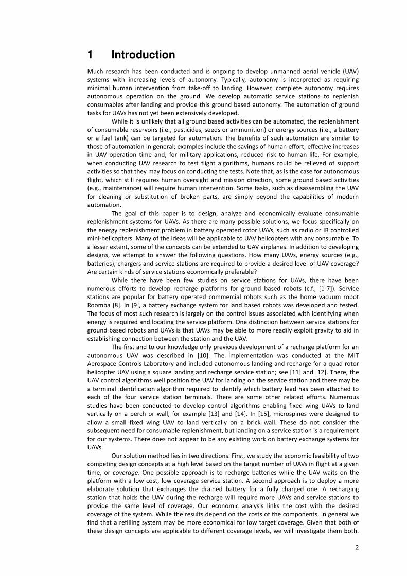
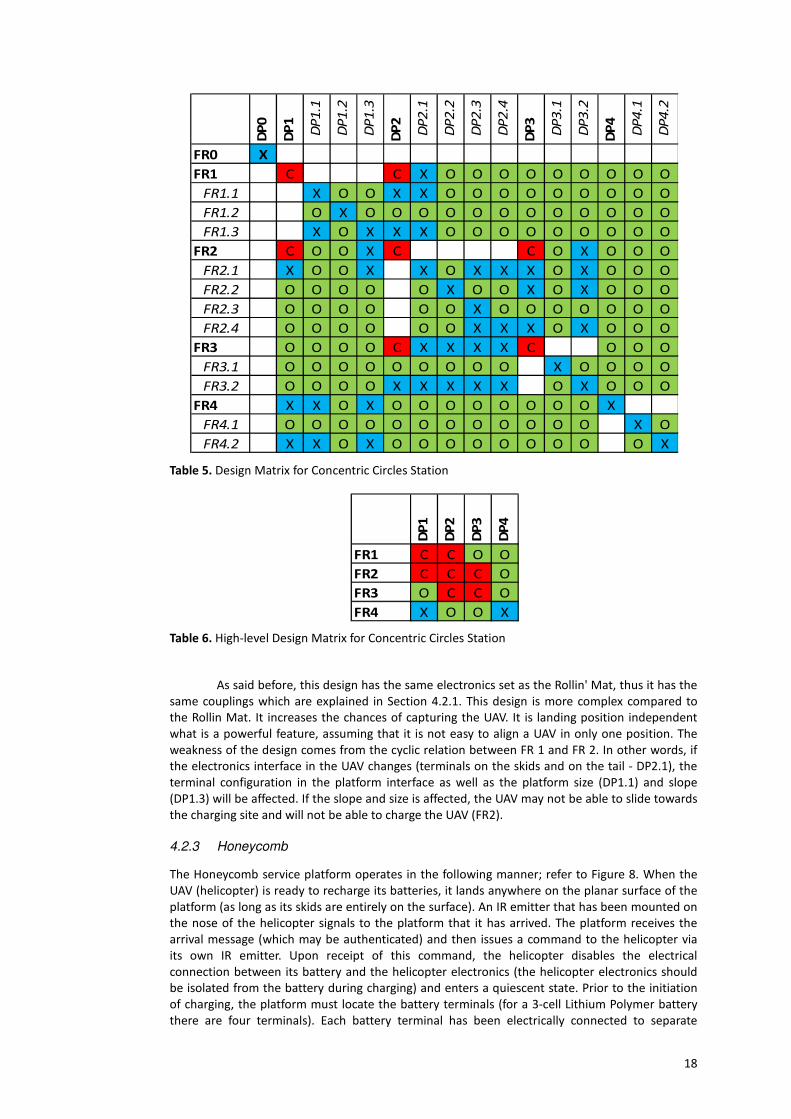
hobbyist/researchers are recreational play, pilot training and data collecting, among others [19].

8

Customer Needs

Military/Security UAVs Farming UAVs Hobbyists/Researchers

1 Charge UAV batteries without human assistance

2 UAV charging process should not damage the UAV

3 Charging platform's geometry which has high probability of successful landing

4 Shape/color of the charging platform is easy to discern from the surroundings, either by

humans or navigation system

5 Erroneous landing on the charging platform inflicts no more damage than erroneous

landing in normal landing pads

6 Parts of charging platform which are potentially harmful to users are out of reach of

humans

7 Simple system set-up

8 Indicates when the process is done, to humans and/or navigation system

9 The charging platform endures regular usage (steady landing, assembly/disassembly)

10 Can be carried out and assembled/disassembled by one average human

11

The charging platform can operate without physical

connection to the power grid or main base

The charging platform does

not use much energy from

the power grid

12

Endures non-ideal weather conditions (light rain, light

snow, wind)

Water resistant (endures

being wet without breaking,

but should not operate wet)

13 Fits different sizes of UAVs Designed for one UAV

14

Allows more than one UAV

to charge at the same time

on the same charging

platform

Charges one UAV at a given time

Table 1 Customer Needs Summary

Different customers also have different design constraints (budget, weight, complexity),

but it is possible to identify some major common constraints; they are summarized in Table 2.

Constraints

1 Modifications to the helicopter, if any, should add as little weight as possible to prevent reduction

in flight duration due to increase of body mass

2 Battery disabling systems must guarantee that the UAV will not be disabled unintentionally

3 UAV dimensions and physical properties

4 The battery is very sensitive to recharging voltage/current (CN1 and CN2)

5 UAV electronics should not be connected to battery during recharging (CN2)

6 Pilot skills/auto-pilot skills (CN4)

7 Human strength/skills (CN10)

Table 2 Design Constraints

3.3 Functional Requirements and Design Parameters

We next provide FRs and DPs that are common at high levels to all customer classes considered.

Decomposition to more detailed FRs and DPs will be discussed in later sections as well as how the

designs differ in complexity and number of functionalities as the design detail increases.

3.3.1 Functional Requirements

The FRs were developed based on the customer needs listed above. For example, CN2 “UAV

charging process should not damage the UAV” was mapped to FR 2.1. In addition to providing

electrical interfaces, FR2.1 will ensure that all electrical components are isolated from each other

(and the environment) unless specifically required to connect. Another example is CN7 “Simple

system set up” which maps to FR 4.1 “Provide easy setup”.

FR1 Provide identifiable landing space

9

FR1.1 Provide sufficient area to land (bigger than 1.5 times the position error of

navigation system and proportional to the number and size of skids/footprint/tail)

FR1.2 Provide means to communicate current position of platform to navigation

solution

FR2 Charge batteries

FR2.1 Provide safe electrical interface between battery on UAV, UAV electronics,

charger on platform, and UAV detection system when appropriate on appropriate linkage

FR2.2 Identify that UAV has landed in correct position

FR2.3 Charge battery

FR2.4 Identify charge needs

FR3 Provide power to the system

FR3.1 Acquire power

FR3.2 Adapt power to be used on the platform

FR4 Provide portability

FR4.1 Provide easy setup

FR4.2 Provide way to transport

3.3.2 Design Parameters

The DPs are the conceptual solutions for each FR. As is the requirement in Axiomatic Design, the

FRs are verb oriented and the DPs are noun oriented. For example, FR3 – "Provide power to the

system" has the corresponding DP3 – “Power supply”. At the high level, it is not uncommon to use

such vague solution concepts in the design process. DP 3 is a very broad solution that is

developed in further detail in later stages of the design.

DP1 UAV Landing platform

DP1.1 Landing area with more than 1.6 times the position error of navigation system

for 1 (or more) UAVs

DP1.2 Visual pattern of sufficient size and complexity to be recognized by the

navigation system

DP2 Charging system

DP2.1 Interface system

DP2.2 UAV detection circuit relying on the presence of the UAV battery (IR/diode

electronics in UAV and platform)

DP2.3 Charger system

DP2.4 Charge need identification system

DP3 Power supply

DP3.1 Connection to the power source (grid, generator or battery)

DP3.2 Power supply circuit

DP4 Features that ensure portability

DP4.1 Single part structure

DP4.2 Carrying case

10

4 Overview of the Designs

In this section, we first introduce the UAVs for which we designed our service stations. We then

provide a brief overview of three designs to accomplish the required functions for energy refill

systems.

4.1 UAVs under Consideration

Since there are many types of UAVs with different energy sources, we select a specific system. We

focus on lithium-polymer battery powered helicopters such as the LAMA V3 [20] and Honey Bee

King 2 [21]. Although we emphasize solutions for refill service stations (which do not require a

removable battery), helicopter models with a detachable power source were chosen in order to

facilitate prototype manufacture.

4.1.1 LAMA V3

The Lama V3 UAV (Figure 2) is a radio controlled coaxial helicopter driven by two electric motors

[20]. It was designed and is manufactured and distributed by E-sky, a Chinese company

specializing in remote control model vehicles. The Lama series helicopters are commercialized as

ready-to-fly (RTF), reserving to the hobbyist the sole task of removing it from the box, then

charging and installing the battery packs in order to fly.

Specifications [20]

Main rotor diameter: 340 mm

Body weight: 215 g (with one 7.4 V 800 mAh (2 cells) Li-polymer battery)

Length: 360 mm, width: 78 mm, height: 168 mm

Power system: 2 E-sky 180-series motors

Transmitter/receiver: 4 channel Frequency Modulation for the radio signal carrier with Pulse

Position Modulation for the control signal

Mix controller: 4-in-1 controller (contains receiver, gyro, mixer, and speed control)

Servos: 2 E-sky 7.5g (1.0 kg·cm, 0.1 sec/60°) servos

Battery: 7.4 V 800 mAh (2 cells) Li-polymer battery

Fig. 2 E-Sky Lama V3 Helicopter (image from http://www.grandhobby.com/lave3eslav3c.html)

4.1.2 HONEY BEE KING 2

The Honey Bee King 2 (Figure 3) is a popular RTF UAV helicopter. Its popularity is due to low cost,

modular components (separated receiver, gyroscope, etc.), belt driven tail rotor and its capability

for more sophisticated aerobatics (including roll, dive and inverted flight). It is a model which is

recommended for more experienced pilots [21] because it requires more attention and training

to master the controls of the rotor and tail pitch.

SPECIFICATIONS [22]

Length: 535mm (Plastic main frame, anodized aluminum tail boom)

Height: 225mm

Main blade diameter: 600mm (CNC machined wooden symmetrical blades)

Tail blade diameter: 130mm

11

Motor gear: 9T

Main drive gear: 140T

Drive gear ratio: 9:140T

Weight: 470g (with one 1000mAh 11.1V 3S LiPo battery)

Fig. 3 E-Sky HoneyBee King 2 Helicopter (image from http://www.sunnykids.cn/pic/SK2422.jpg)

4.2 Solutions Developed

Here we discuss three solutions for refill service stations. They differ in cost, capability and

coupling of functions.

4.2.1 Rollin’ Mat

The Rollin’ Mat is intended for hobbyists and moderately experienced pilots (or controllers) and is

depicted in Figure 4. A prototype is shown in Figure 5. The Rollin’ Mat operates as follows. When

the UAV is ready for battery recharge, it approaches the platform. The three terminals of the two

cell Lithium Polymer (LiPo) battery on the UAV are each connected to three different locations on

the UAV feet and tail. Figure 4 depicts the location of the 7.4V, 3.7V and GND terminals on the

UAV. The Rollin’ Mat consists of a flat rectangular mat (it can be made of EVA) with parallel

rectangular wire mesh bands that serve as terminals connected to the charger. Figure 4 depicts

such a Rollin’ Mat where each terminal is labelled 7.4V, 3.6V and GND according to their voltage

expectations.

The UAV pilot (human operator or computer) is responsible for landing the UAV on the

Rollin’ Mat such that the 7.4V, 3.6V and GND terminals on the feet match the same voltage

terminals on mat. Thus, successful terminal alignment relies upon the pilot’s ability. That is,

“FR2.3 – Charge battery” depends heavily on the user to match the interface terminal correctly.

The charge process will only be established if the pilot of the UAV manages to land it with the

right orientation and reasonable terminal match. Once this is done, the charging process will

initiate.

The simplicity of the design suggests that it may be useful for military land troops; it is

easy to install and light weight. It need only be laid flat and it is ready for service.

The Rollin’ Mat was designed for small and easy to fly UAVs such as the Lama V3. Since

the batteries used in these types of UAVs are made of lithium-polymer, the terminal matching

from the platforms with the UAVs must be done carefully. The Lama V3 has a two-cell battery

(three terminals needed) and the Honey Bee King 2 uses a three-cell battery (four terminals

needed). For the Lama V3, one terminal is placed on the front and one on the rear of the skids

and the third terminal is placed on the helicopter’s tail (Figure 4).

12

Fig. 4. Rollin’ Mat Station Diagram

Fig. 5. Rollin' Mat Station Prototype

Target Customer: Weekend “Light” User / Office Hobbyist / High-mobility troops

Second level Functional Requirements and Design Parameters for the Rollin’

Mat

FR1 Provide identifiable landing space

FR1.1 Provide sufficient area to land

(bigger than 1.5 times the position

error of navigation system and

proportional to number and size of

skids/footprints/tail)

FR1.2 Provide means to

communicate current position of

platform to navigation solution

FR2 Charge batteries

FR2.1 Provide safe electrical

interface between battery on UAV,

UAV electronics, charger on platform,

and UAV detection system when

appropriate on appropriate linkage

-

DP1 UAV Landing platform - flat mat

DP1.1 Landing area with more than

1.6 times the position error of

navigation system for 1 (or more)

UAVs

-

DP1.2 Visual pattern of sufficient

size and complexity to be recognized

to the navigation system

DP2 Charging system

DP2.1 Interface system that

provides connection between UAV

and platform. On the UAV, skids and

tail have terminals while the platform

has wire mesh bands that match the

placement of the battery terminals

13

-

FR2.2 Identify that UAV has landed

in correct position

-

-

FR2.3 Charge battery

FR2.4 Identify charge needs

-

FR3 Provide power to system

FR3.1 Acquire power

-

FR3.2 Adapt power to be used on

the platform

FR4 Provide portability

FR4.1 Provide easy setup

FR4.2 Provide way to transport

located on the UAV

DP2.2 UAV detection circuit relying

on the presence of the UAV battery

(IR/diode electronics in UAV and

platform)

DP2.3 Charger system

DP2.4 Charge need identification

system

DP3 Power supply

DP3.1 Connection to the power

source (grid, generator or battery)

DP3.2 Power supply circuit

-

DP4 Features that ensure portability

DP4.1 Single part structure

DP4.2 Foldable platform made out

of ethylene-vinyl acetate (EVA)

FR1 requires an area for the UAV to land. This platform must provide a landing area

greater than 1.5 times the error of the navigation system (FR1.2) so as to increase the probability

of a successful landing on the landing platform. If the navigation system can land the UAV with a

precision of 10 cm in radius, then the platform is required to be greater than 15 cm in radius

(DP1.1 requires 16 cm in radius to accomplish FR1.2 in this case). To communicate its position

to the Rollin’ Mat (FR1.2), the platform will provide a detectable pattern of sufficient size (DP1.2).

If instead of a navigation system, for example, there was a human pilot, then the visual pattern

can be a color which is easily discerned from the ambient, or some LED pattern that can be

recognizable at distance. If the navigation system is a machine, then an infra-red camera and

infra-red LEDs could also be a solution in DP 1.2.

FR2, which is “Charge batteries”, is decomposed into providing safe electrical interface

between the UAV electronics, platform electronics and connection between them (FR2.1),

identifying UAV landing position (FR2.2), recharging the battery (FR2.3) and identifying charging

needs (FR2.4). In order to have a safe interface that can guarantee that the battery will be

charged, first, the UAV must have terminals linked to the battery which are attached to the UAV

skids and tail (see Figure 4). For safety, the battery is disconnected from the terminals on the

skids by a relay that is only activated when the proper connection/landing is made on the

platform. Since the UAV will be touching the platform, the platform too must have a safe way to

interface both terminals. The flat mat platform has wire mesh terminals, whose arrangement

matches the physical configuration of the battery terminals linked to the UAV skids and tail. The

wire mesh bands are linked to the OEM charger through a relay that is only actuated to turn on

this link when the UAV has landed in the correct position. To make sure that the relays are

activated only when the UAV is in the correct landing position, there is a UAV detection circuit

(DP2.2). The communication between platform and UAV is made via an infrared emitter and

receiver placed on the center of the platform and helicopter. The platform is responsible for

identifying the UAV’s position in order to match the battery terminals. When terminal matching is

completed, the communication system turns off the UAV and sends a signal to the platform

indicating that the charging process may begin. The charging process is conducted by an OEM

charger based electronics system (DP2.3). While the charger charges the battery, the “Charge

need identification system” (DP2.4) is reading the signals from it and interpreting flags such as

“charge is finished”, “there is a problem with the battery” or “it is not charging”.

Electric/electronic devices require electricity. FR3 addresses this need by acquiring

power (FR3.1) and adapting this power (FR3.1) to be used in the platform, stabilizing it and

transforming it to the right DC level (FR3.2). This is easily achieved by having a connection to the

14

power grid, generator or battery (DP3.1) and by adding a power supply circuit (for power

stabilization using capacitor banks) and a 12VDC power supply converter (DP3.2).

Features such as portability are required in FR4. To provide easy set up (FR4.1) and

transport (FR4.2), a single part structure (DP4.1) made of a foldable material (EVA) that can be

rolled into a small pack (DP4.2) and easily carried is employed.

To analyze the design, a Design Matrix is constructed to determine where design

couplings (or cyclic relations) exist between the FRs and DPs for the Rollin’ Mat:

Table 3. Design Matrix for Rollin’ Mat Station

The design matrix (DM) presented in Table 3, as explained in Section 3.1, is a matrix

representation to visualize interrelations between functional requirements and design

parameters. To express what kind of relation the FRs and DPs have with each other, symbols such

as blank spaces, "O"s, "X"s and "C"s are used to describe "parent-child relationship", "there is no

relationship", "there is a unidirectional relationship" and "there is a cyclic relationship"

respectively.

As shown in the DM of Table 3, FR 2.1, 2.2 and 2.4 (functions that are related to

electronic component safety, battery charging and identification of charge needs, respectively)

depend upon "DP3.2 Power supply circuit". Also, FR 3.2 depends upon DPs 2.1, 2.2, 2.3 and 2.4.

These dependencies form a cyclic relationship and cause the DM to be coupled. This appears

inevitable since many child functions under FR2 (i.e., FR2.1, FR2.2 and FR2.4) request energy and

their fulfillment is thus a function of the power supply circuit (DP3.2). Similarly, to provide FR 3.2,

we must be aware of the solutions for DP 2. Also, the proper sizing of the power supply (DP3.2)

depends on how much energy is drawn by the circuitry responsible for FR2. Nevertheless, this

cyclic relation (coupling) is well understood by product engineers and does not pose any major

challenge in accomplishing the complete system design. Since it is present in the other designs as

well, we will not further discuss the relationships between FRs 2 and 3 in those designs. The cyclic

relation can be seen easily by looking to the high-level (or reduced) form of the DM, as seen in

Table 4.

Table 4. High-level Design Matrix for Rollin’ Mat Station

DP

1

DP

1.1

DP

1.2

DP

2

DP

2.1

DP

2.2

DP

2.3

DP

2.4

DP

3

DP

3.1

DP

3.2

DP

4

DP

4.1

DP

4.2

FR1 X X X O O O O O O O O O

FR1.1 X O X X O O O O O O O O O

FR1.2 O X O O O O O O O O O O O

FR2 O O O C C O X O O O

FR2.1 O O O X O X X X O X O O O

FR2.2 O O O O X O O X O X O O O

FR2.3 O O O O O X O O O O O O O

FR2.4 O O O O O X X X O X O O O

FR3 O O O C X X X X C O O O

FR3.1 O O O O O O O O X O O O O

FR3.2 O O O X X X X X O X O O O

FR4 X X O O O O O O O O O X

FR4.1 O O O O O O O O O O O X O

FR4.2 X X O O O O O O O O O O X

DP

1

DP

2

DP

3

DP

4

FR1 X X O O

FR2 O C C O

FR3 O C C O

FR4 X O O X

15

If we choose to ignore this FR2 and FR3 coupling, as it is present in almost any electronic

design, it is possible to say that the design is decoupled, which means that although it is not an

ideal design with a diagonal matrix there are no (other) cyclic relations between the FRs and DPs.

The other “X” values in the design matrix represent unidirectional relationships. For example,

DP2.1 influences FR1.1. This is because the placement and size of the terminals on the mat

(which depend on the UAV size) naturally influence the size of the mat. In particular, if the UAV is

very small, it may be difficult to have the mat and the terminals to be of greater area than 1.5

times the landing position accuracy. On the other hand, the size of the mat will not influence the

arrangement of terminals on the UAV skids and tail (so long as it will fit on the mat).

4.2.2 Concentric Circles

The concentric circle design is shown in Figure 6; a prototype is depicted in Figure 7. It is intended

for inexperienced pilots, a low precision automatic controller and adverse weather conditions.

This platform operates similarly to the Rollin’Mat except that the platform has a different

geometry. It consists of a wide donut shape platform that guides the helicopter to the charging

site, facilitating the landing. No extra guidance is required because the platform terminals are

shaped into concentric circles of conducting material. The helicopter terminals are deployed on

the skids in such a way as to guarantee that the terminal match is independent of the helicopter

orientation. That is, one helicopter terminal is placed on the geometrical center of the skids (to

match the circle center) and the others are placed at locations whose radii from the center of the

skid matches the radii of the circular platform terminals.

Fig. 6. Concentric Circles Station Diagram

16

Fig. 7. Concentric Circles Station Prototype

Target Customer: Farming UAVs companies

Second Level Functional Requirements and Design Parameters for

Concentric Circles

FR1 Provide identifiable landing space

FR1.1 Provide sufficient area to land

(bigger than 1.5 times the position error

of navigation system and proportional to

number and size of skids/footprints/tail)

FR1.2 Provide means to communicate

current position of platform to navigation

solution

FR1.3 Provide means to bring UAV to

recharging area

-

FR2 Charge batteries

FR2.1 Provide safe electrical interface

between battery on UAV, UAV

electronics, charger on platform, and

UAV detection system when appropriate

on appropriate linkage

-

-

-

-

FR2.2 Identify that UAV has landed in

correct position

-

FR2.3 Charge battery

FR2.4 Identify charge needs

-

FR3 Provide power to system

FR3.1 Acquire power

FR3.2 Adapt power to be used on the

platform

FR4 Provide portability

FR4.1 Provide easy setup

FR4.2 Provide way to transport

DP1 UAV Landing platform - donut platform.

DP1.1 Landing area with more than

1.6 times the position error of

navigation system for 1 (or more) UAVs

-

DP1.2 Visual pattern of sufficient size

and complexity to be recognized to the

navigation system

DP1.3 Donut shape platform where

UAV slides on a slope to reach the area

where recharging will take place

DP2 Charging system

DP2.1 Interface system that provides

connection between UAV and platform

independent of UAV landing orientation

on landing. On the UAV, the skids and

tail have terminals while the platform

has metal ring bands placed concentric

to each other that match the placement

of the battery terminals located on UAV

DP2.2 UAV detection circuit relying on

the presence of the UAV battery

(IR/diode electronics in UAV and

platform)

DP2.3 Charger system

DP2.4 Charge need identification

system

DP3 Power supply

DP3.1 Connection to the power

source (grid, generator or battery)

DP3.2 Power supply circuit

DP4 Features that ensure portability

DP4.1 Single part structure

DP4.2 Case

Gross UAV positioning is provided by an external platform consisting of a donut shape

platform (DP1.3) that increases the effective area for the helicopter to land and guides it to a

charging site located at its center.

The battery terminals are connected to points on the helicopter skids and tail in a similar

way to the Rollin Mat, explained in the previous subsection. These UAV terminals must touch the

17

platform terminals (DP2.1) in such a way as to avoid short-circuits. The helicopter terminals are

positioned on the skids in a way that whenever the helicopter lands, it connects to the desired

platform terminals to initiate the charging state while ensuring no shorts.

In the center of the platform, there are concentric ring shaped terminals that allow the

helicopter to establish connection between the helicopter battery terminals on the skids and the

charger terminals (the concentric ring terminals as platform interface system) independent of the

orientation of the helicopter once it slides to the center. There is no need for terminal detection-

assignment (active matching system or dynamic terminal allocation), since the terminals match

automatically based on the geometry.

To verify that the terminals have correctly matched and are all in contact, there is a

presence detection system that checks the helicopter presence via voltage readings (DP2.2).

Until this point, for safety reasons, the battery is kept disconnected from the helicopter

skid terminals. When the platform system identifies that the helicopter is in the right position (via

the previously mentioned presence detection system), the platform sends a signal through

infrared emitter diode (IRED) periodically so that the helicopter onboard device understands that

the battery should be connected to the platform to provide charging and disconnected from the

helicopter electronics (DP2.2).

If the onboard electronics do not receive the IR information for a certain period of time,

it understands that it should reconnect the helicopter electronics to the battery, allowing it to fly

and reposition.

The concentric circles station also has a coupling between FR-DP 2 and 3, which can be

observed in Table 5 and is explained in the previous section (the Rollin Mat and Concentric Circles

designs have a similar set of FR and DPs for levels 2 and 3). The next cyclic coupling arises from

the outer guiding donut shell being responsible for the physical form of the platform (DP1.3) and

UAV terminal matching/connection (DP2.1). In other words, if the UAV does not land in the right

position, it is not able to slide down the donut shape platform, thus not reaching the charging site

and its terminals. The size of the platform and its shape depends initially on the placement of

terminals on the skids and on the tail of the UAV as well as the size of the skids and location of

the tail. The skids affect the size of the internal diameter of the platform because the helicopter is

being guided to platform center, which must accommodate the UAV tightly, in order to match its

skids' interface terminals to the platform charging terminals. If the core diameter of the platform

is too large in comparison with the UAV skids, proper matching of terminals will not happen and

UAV can slide to a place where it is misaligned in relation to the concentric metal ring terminals of

its center. The location of the tail will be related to the outer part of the donut shell. If the donut

shell is too large in comparison to the location of the tail, they will collide in landing and platform

cannot match the size of the UAV. In summary, the size of the UAV interface terminals on the skids

and on the tail depends on the platform interface terminals and the size of the platform donut. As

a consequence of the platform size being linked with the UAV size, the slope that guides the

helicopter to the charging site is also affected.

The matrix to analyze couplings is shown in Table 5. The high-level matrix is shown in

Table 6.

18

Table 5. Design Matrix for Concentric Circles Station

Table 6. High-level Design Matrix for Concentric Circles Station

As said before, this design has the same electronics set as the Rollin' Mat, thus it has the

same couplings which are explained in Section 4.2.1. This design is more complex compared to

the Rollin Mat. It increases the chances of capturing the UAV. It is landing position independent

what is a powerful feature, assuming that it is not easy to align a UAV in only one position. The

weakness of the design comes from the cyclic relation between FR 1 and FR 2. In other words, if

the electronics interface in the UAV changes (terminals on the skids and on the tail - DP2.1), the

terminal configuration in the platform interface as well as the platform size (DP1.1) and slope

(DP1.3) will be affected. If the slope and size is affected, the UAV may not be able to slide towards

the charging site and will not be able to charge the UAV (FR2).

4.2.3 Honeycomb

The Honeycomb service platform operates in the following manner; refer to Figure 8. When the

UAV (helicopter) is ready to recharge its batteries, it lands anywhere on the planar surface of the

platform (as long as its skids are entirely on the surface). An IR emitter that has been mounted on

the nose of the helicopter signals to the platform that it has arrived. The platform receives the

arrival message (which may be authenticated) and then issues a command to the helicopter via

its own IR emitter. Upon receipt of this command, the helicopter disables the electrical

connection between its battery and the helicopter electronics (the helicopter electronics should

be isolated from the battery during charging) and enters a quiescent state. Prior to the initiation

of charging, the platform must locate the battery terminals (for a 3-cell Lithium Polymer battery

there are four terminals). Each battery terminal has been electrically connected to separate

DP

0

DP

1

DP

1.1

DP

1.2

DP

1.3

DP

2

DP

2.1

DP

2.2

DP

2.3

DP

2.4

DP

3

DP

3.1

DP

3.2

DP

4

DP

4.1

DP

4.2

FR0 X

FR1 C C X O O O O O O O O O

FR1.1 X O O X X O O O O O O O O O

FR1.2 O X O O O O O O O O O O O O

FR1.3 X O X X X O O O O O O O O O

FR2 C O O X C C O X O O O

FR2.1 X O O X X O X X X O X O O O

FR2.2 O O O O O X O O X O X O O O

FR2.3 O O O O O O X O O O O O O O

FR2.4 O O O O O O X X X O X O O O

FR3 O O O O C X X X X C O O O

FR3.1 O O O O O O O O O X O O O O

FR3.2 O O O O X X X X X O X O O O

FR4 X X O X O O O O O O O O X

FR4.1 O O O O O O O O O O O O X O

FR4.2 X X O X O O O O O O O O O X

DP

1

DP

2

DP

3

DP

4

FR1 C C O O

FR2 C C C O

FR3 O C C O

FR4 X O O X

19

points on the base of the helicopter skid so that they are in contact with the hexagon cells that

make up the surface of the platform. The platform control unit scans its constituent hexagon cells

to identify which ones are host to a battery terminal (via the skid) and identifies the voltages

present on each. With this information, the platform controller connects the terminals of its

battery charger to the appropriate hexagon cells (and thus the battery terminals); charging is

initiated. Once charging is complete, the platform controller disconnects the charger from the

cells and issues a release command to the helicopter. This command signals the helicopter to

reconnect its own internal circuits (thereby establishing connection between the battery and the

helicopter electronics) and the process is complete. The helicopter, with battery fully charged,

may take flight to complete its objectives.

Fig. 8. Honeycomb Station Diagram

Due to the fact that the platform identifies the location of the helicopter battery

terminals (based on their voltage) it does not matter in what orientation the helicopter lands (so

long as all battery terminals on the skids are in contact with the platform). As the platform’s

planar surface may be readily expanded by the connection of additional hexagonal cells (or the

cells may be enlarged), a variety of helicopter sizes can be accommodated. One key to allowing

this feature is to ensure that there is a minimum distance between battery terminals on the

helicopter skids (this distance determines the dimensions of each hexagon, as seen in Figure 8).

To minimize the number of hexagon cells required, their radius should be as large as possible (and

their number should be dictated by the desired platform size).

The safety of UAV electronics is ensured by preventing shorts between the battery’s

terminals on landing. One way to ensure that a hexagonal cell does not pose a threat to UAV

integrity is to limit its dimensions to be smaller than the distances between any two terminals on

the UAV. For a system of UAVs, the smallest UAV should set this constraint. As an example, in

Figure 9, the distance between terminals A and B (dAB) is the smallest distance between any two

terminals for that UAV. Therefore, the dimension D of the hexagonal cells should be smaller than

dAB to prevent short circuit on landing.

20

Fig. 9. Hexagon Cell Dimension Constraint

As described, the Honeycomb service platform operates independently of the helicopter

landing orientation, size (within physical limits such as weight), and terminal location. Further,

each hexagonal cell has a modular design. In addition, the platform controller can be configured

to allow multiple helicopters to employ the same platform simultaneously (so long as there is

sufficient clearance to accommodate them).

Target Customer: Military, Homeland Security, Traffic Control Agencies

Second Level Functional Requirements and Design Parameters for the

Honeycomb

FR1 Provide identifiable landing space

-

FR1.1 Provide sufficient area to land

(bigger than 1.5 times the position

error of navigation system and

proportional to number and size of

skids/footprints/tail)

FR1.2 Provide means to

communicate current position of

platform to navigation solution

FR2 Charge batteries

FR2.1 Provide safe electrical

interface between battery on UAV,

UAV electronics, charger on platform,

and UAV detection system when

appropriate on appropriate linkage

-

-

FR2.2 Identify that UAV has landed

FR2.3 Charge battery

FR2.4 Identify charge needs

-

FR3 Provide power to system

DP1 UAV Landing platform - honeycomb

platform.

DP1.1 Landing area with more than

1.6 times the position error of

navigation system for 1 UAVs

-

-

DP1.2 Visual pattern of sufficient

size and complexity to be recognized

to the navigation system

DP2 Charging system

DP2.1 Interface system that

provides connection between UAV

and platform independent of UAV

orientation on landing. On the UAV,

skids have terminals while the

platform is made of several hexagon-

shaped terminals

DP2.2 UAV detection circuit relying

on the presence of the UAV battery (IR

communication system on UAV and

platform)

DP2.3 Charger system

DP2.4 Charge need identification

system

21

FR3.1 Acquire power

-

FR3.2 Adapt power to be used on

the platform

FR4 Provide portability

FR4.1 Provide easy setup

FR4.2 Provide way to transport

DP3 Power supply

DP3.1 Connection to the power

source (grid, generator or battery)

DP3.2 Power supply circuit

-

DP4 Features that ensure portability

DP4.1 Straight forward way to

connect cell arrays

DP4.2 Case

The matrix to analyze couplings is shown in Table 7. The high-level matrix is shown in Table 8.

Table 7. Design Matrix for Honeycomb Station

Table 8. High-level Design Matrix for Honeycomb Station

Except for the cyclic relation already explained in Section 4.2.1, there are no other cyclic

relations.

Numerous features of the Honeycomb service platform were inspired (and subsequently

developed) by the consideration of functional independence as dictated by the AD methodology.

First, the system is readily expandable: numerous helicopters can be charged simultaneously by

adding more cells and charger devices. Another feature is that the wireless IR emitter/sensor

communication system can be readily replaced with another wireless system. Also, due to the

independence of functions and modular design, alternative solutions can be substituted for

DP

1

DP

1.1

DP

1.2

DP

2

DP

2.1

DP

2.2

DP

2.3

DP

2.4

DP

3

DP

3.1

DP

3.2

DP

4

DP

4.1

DP

4.2

FR1 X O O O O O O O O O O O

FR1.1 X O O O O O O O O O O O O

FR1.2 O X O O O O O O O O O O O

FR2 X X O C C O X O O O

FR2.1 X X O X O X X X O X O O O

FR2.2 O O O O X O O X O X O O O

FR2.3 O O O O O X O O O O O O O

FR2.4 O O O O O X X X O X O O O

FR3 O O O C X X X X C O O O

FR3.1 O O O O O O O O X O O O O

FR3.2 O O O X X X X X O X O O O

FR4 X X O O O O O O O O O X

FR4.1 X X O O O O O O O O O X O

FR4.2 X X O O O O O O O O O O X

DP

1

DP

2

DP

3

DP

4

FR1 X O O O

FR2 X C C O

FR3 O C C O

FR4 X O O X

22

existing ones so long as the alternate DPs do not introduce additional coupling.

Despite possessing a matrix that is similar to the Rollin' Mat design presented earlier, it

can charge the helicopter battery independent of the position (e.g. Concentric Circles), with no

extra cyclic couplings. The unidirectional relations arise from the requirement that the platform

charge multiple UAVs at the same moment. This influences the size of the platform (FR2.1-DP1.1),

which is directly proportional to the number of hexagon cells. If the platform becomes too big,

the functions of easy setup (FR4.1) and provide a way to transport (FR4.2) may be influenced.

The Honeycomb service platform can be used in virtually any situation where recharging

is needed. As low cost microcontrollers and moderate complexity are present in every cell, this

solution is more expensive than the alternate designs presented. Thus, the Honeycomb service

platform is recommended for applications where precise landing on a small platform may be

difficult due to weather conditions or flight control intelligence/capability. It is our opinion that

military and, particularly, surveillance application areas may find this design useful. Another

target application area is agricultural UASs on severe weather areas.

By using arrays of Honeycombs, one can eliminate the need for round trips. For example,

instead of limiting the maximum range to less than half of the UAV’s maximum range to ensure

that the UAV can return to the home base, one can employ service platforms in the field to allow

the UAV to reach its maximum range in travelling from one platform to the other. This approach

will serve to enhance the coverage area of a single UAV (Figure 10). Each platform controller that

is deployed could be equipped with a signal repeater to ensure that the broadcast from the

helicopter controller will be received by the helicopter as it grows more distant from the

command source (operator or control software).

Fig. 10. Coverage Area

5 Design Evaluation

Here we provide brief commentary on the cost and complexity of the various designs. We use

complexity as a surrogate to estimate the cost of the service system designs. From an EVA and

wire mesh structure (The Rollin’ Mat) to an array of microcontroller equipped devices

(Honeycomb) there is a significant price gap. Here follows the main component list for each

design:

Rollin’ Mat: EVA mat, wire mesh, wiring, IR LEDs, IR phototransistors, one low cost

microcontroller, two double-push-double-throw (DPDT) relays, one OpAmp;

Concentric Circles: Outside donut-shaped shell made of shock resistant material, wire mesh,

wiring, IR LEDs, IR phototransistors, one low cost microcontroller, two DPDT relays, one OpAmp;

Honeycomb: Several microcontrollers (one per cell plus one master), casing for all cells, solid

state relay array on each cell, IR LEDs and phototransistors proportional to the number of cells.

In Figure 11, we provide an illustrative summary of the cost and complexity of the three designs.

23

Fig. 11. Comparative Graphic between Complexity and Cost of Stations

6 Battery Exchange Systems

Although battery recharging systems may be a very attractive option for UAVs powered by fixed

batteries, they can require a long time to recharge (around two hours for the LAMA V3) [20].

Instead of recharging (or refilling) the energy reservoir, we have the option to exchange it. One

can also provide functions such as battery replacement, fuel tank exchange, pesticide tank

replacement, etc. The empty reservoirs would then be replenished while at the station, so they

can be reused later.

Physical realization of such devices was not the goal of this paper. One possible

conceptual implementation of a battery exchange system is displayed below (Figure 12). For this

battery exchange system, we defined specific functional requirements such as position the UAV,

change the UAV battery, recharge batteries, store batteries and transport of batteries within the

station.

Figure 12 depicts the concept. This concept consists of a set of batteries which are held

by small carrier vehicles. These vehicles are guided through a circular path in the station. Each of

these vehicles is equipped with one battery charging device. In Figure 12-1, the UAV approaches

the station and lands on it. Here we assume that the UAV is guided to an elevator by a solution

similar to the guiding donut of Concentric Circles. In Figure 12-2, the elevator is actuated,

lowering the UAV to the battery exchange site. In Figure 12-3, the UAV battery holder is actuated

by a set of pins located on station floor, thus releasing the UAV’s battery into a vacant carrier

vehicle. Next, in Figure 12-4, while the UAV battery holder is still open, the station positions a

second carrier vehicle which has a fully charged battery into the replacement site. In Figures 12-5

and 12-6, the elevator is again actuated upwards while the battery container closes itself

automatically, ensuring that the UAV captures the recharged battery. In Figure 12-7, the UAV has

completed the battery replacement procedure and is ready to take off. Figure 12-8 shows a

schematic of the carrier vehicle in the station track/path.

24

Fig. 12. Battery Exchanging Station Concept

Using an exchange process could increase significantly the ratio of maximum possible

flight time (from take off to landing) per ground time, therefore, decreasing the total number of

UAVs. On the other hand, implementation cost will increase, since exchanging an empty reservoir

for a full one is a more sophisticated approach than simply charging a waiting UAV.

7 Concluding Remarks

For systems of UAVs to achieve near autonomy, the automation of ground tasks is required. To

address this problem we first conducted an economic evaluation of two solutions concepts: refill

and exchange of consumable reservoirs. We demonstrated that refilling stations are economically

superior for low target coverage. For high coverage systems, exchange stations are better.

We developed three stations focusing on low cost, battery integrated UAVs to address

different needs such as portability (Rollin’ Mat) or difficult landing conditions (Concentric Circles

and Honeycomb) by the use of Axiomatic Design. We compared the designs in terms of cost and

complexity. Less complex but cheaper designs require more piloting skills while higher technology

and greater cost solutions may reduce the navigational requirements. Implementation of these

service platform concepts can lead to drastically reduced need for operators to maintain system

operation. These concepts have the potential to reduce cost of operation, reduce risk to human

lives, increase operating distance and increase self-sustained operational time. Therefore,

systems for the automatic replenishment of UAV energy reservoirs can serve as an enabling

technology for the complete autonomy of systems of UAVs.

In addition, we introduced a concept for consumable reservoir exchange systems (e.g.,

battery exchange). The consumable reservoir exchange station may be more suitable for high

coverage systems of UAVs, compensating a high implementation cost with greater individual UAV

coverage.

Acknowledgements This work was supported in part by KAIST URP Fall 2008 grant 082-2-18.

25

8 References

[1] M.C. Silverman, D. Niles, B. Jung and S. Sukhatme, “Staying alive: A docking station for

autonomous robot charging,” Proceedings of the 2002 IEEE International Conference on Robotics

and Automation, Washington D. C., USA, May 11-15, 2002, pp. 1050-1055.

[2] M.C. Silverman, D. Niles, B. Jung and S. Sukhatme, “Staying alive longer: Autonomous

robot recharging put to the test,” Center for Robotics and Embedded Systems (CRES) Technical

Report CRES-03-015, University of Southern California, 2003.

[3] G. Parker, R. Georgescu, and K. Northcutt, “Continuous power supply for a robot colony,”

Proceedings of the World Automation Congress (WAC 2004), June 2004.

[4] P. Zebrowski and R. Vaughan, “Recharging robot teams: A tanker approach,” Proceedings

of the 2005 International Conference on Advanced Robotics (ICAR’05), Seattle, Washington, USA,

July 18-20, 2005.

[5] K. H. Kim, H. D. Choi, S. Yoon, K. W. Lee, H. S. Ryu, C. K. Woo and Y. K. Kwak,

“Development of docking system for mobile robots using cheap infrared sensors,” Proceedings of

the 1st

International Conference on Sensing Technology, Palmerston North, New Zealand,

November 21-23, 2005, pp. 287-291.

[6] G. B. Parker and R. S. Zbeda, “Controlled use of a robot colony power supply,”

Proceedings of the 2005 IEEE International Conference on Systems, Man and Cybernetics (SMC

2005), October 2005, pp. 3491-3496.

[7] R. Cassinis, F. Tampalini, P. Bartolini and R. Fedrigotti, “Docking and Charging System for

Autonomous Mobile Robots,” technical report, Università degli Studi di Brescia. Available at

http://www.ing. unibs.it/~cassinis/docs/papers/05_008.pdf, website accessed April 13, 2010.

[8] Roomba vacuum robot from iRobot Corporation, http://www.irobot.com/, website accessed

April 14, 2010.

[9] Y. C. Wu, M. C. Teng and Y. J. Tsai, “Robot docking station for automatic battery

exchanging and charging,” Proceedings of the 2008 IEEE International Conference on Robotics and

Biomimetics, Bangkok, Thailand, February 21-26, 2009, pp. 1043-1046.

[10] D. Dale and J. P. How, “Automated ground maintenance and health management for

autonomous unmanned aerial vehicles,” Thesis (M. Eng.), Massachusetts Institute of Technology,

Department of Electrical Engineering and Computer Science, 2007. Available from

http://hdl.handle.net/1721.1/41541, website accessed April 14, 2010.

[11] MIT Aerospace Controls Lab video, http://acl.mit.edu/mediaroom, link to Videos �

SWARM Health Mgmt � ICRA 2007 Video (Jan 2007) � 1:47 min:sec into the video, website and

video accessed December 2, 2009.

[12] J. P. How, B. Bethke, A. Frank, D. Dale and J. Vian, “Real-time indoor autonomous vehicle

test environment”, IEEE Control Systems Magazine, Vol. 28, No. 2, April 2008.

[13] R. Cory and R. Tedrake, “Experiments in fixed-wing UAV perching,” Proceedings of the

AIAA Guidance, Navigation and Control Conference, Honolulu, Hawaii, USA, August 18-21, 2008.

[14] A. Frank, J. S. McGrew, M. Valenti, D. Lavine, J. P. How, “Hover, transition and level flight

control design for a single-propeller indoor airplane,” Proceedings of the AIAA Guidance,

Navigation and Control Conference, Hilton Head, South Carolina, USA, August 20-23, 2007.

[15] A. L. Desbiens and M. Cutkosky, “Landing and perching on vertical surfaces with

microspines for small unmanned air vehicles,” Proceedings of the International Symposium on

Unmanned Aerial Vehicles, Reno, Nevada, USA, June 8-10, 2009.

[16] Nam Pyo Suh, Axiomatic Design - Advances and Aplications. New York: Oxford University

Press, 2001.

[17] Nam Pyo Suh, The Principles of Design. New York: Oxford University Press, 1990.

[18] Karl T Ulrich and Steven D, Eppinger, Product design and development.: McGraw-Hill,

2008.

[19] Robert Finkelstein, Robotic Technology Inc. website,

http://www.robotictechnologyinc.com/images/upload/file/The_Ubiquitous_UAV.pdf, website

accessed August 19, 2010

[20] LAMA V3 information manual, http://en.esky-sz.cn/home.html, link to Products � MHz

Helicopter � 300 Series� LAMA V3 information and manual, website accessed August 19, 2010.

[21] EflightWiki information page on the Honey Bee King V2, http://www.eflightwiki.com/

�Search “Esky Honey Bee King”, link for Honey Bee King V2, website accessed December 9, 2009.

26

[22] Honey Bee King 2 information manual, http://www.twf-sz.com/english/, link to Products

� MHz Helicopter � 500 Series� Honey Bee King 2 information and manual, website accessed

December 9, 2009.


Recommended