21
UCLH PROTON BEAM THERAPY CENTRE Leveraging the benefits of geotechnical software and modelling
UCLH PROTON BEAM THERAPY CENTRE
Leveraging the benefits of geotechnical software and modelling

The team Bouygues UK – Principal Contractor
CampbellReith – Principal Designer
McGee – Demolition, Excavation
Dam Structures – Propping
Fayat – Diaphragm Walling, Piling
Stuart Well – Dewatering
Getec – Monitoring
Byrne Looby – Dwall and Piling Designer
Bell Johnson – Prop Designer
A-squared – Independent Design Review for Bouygues
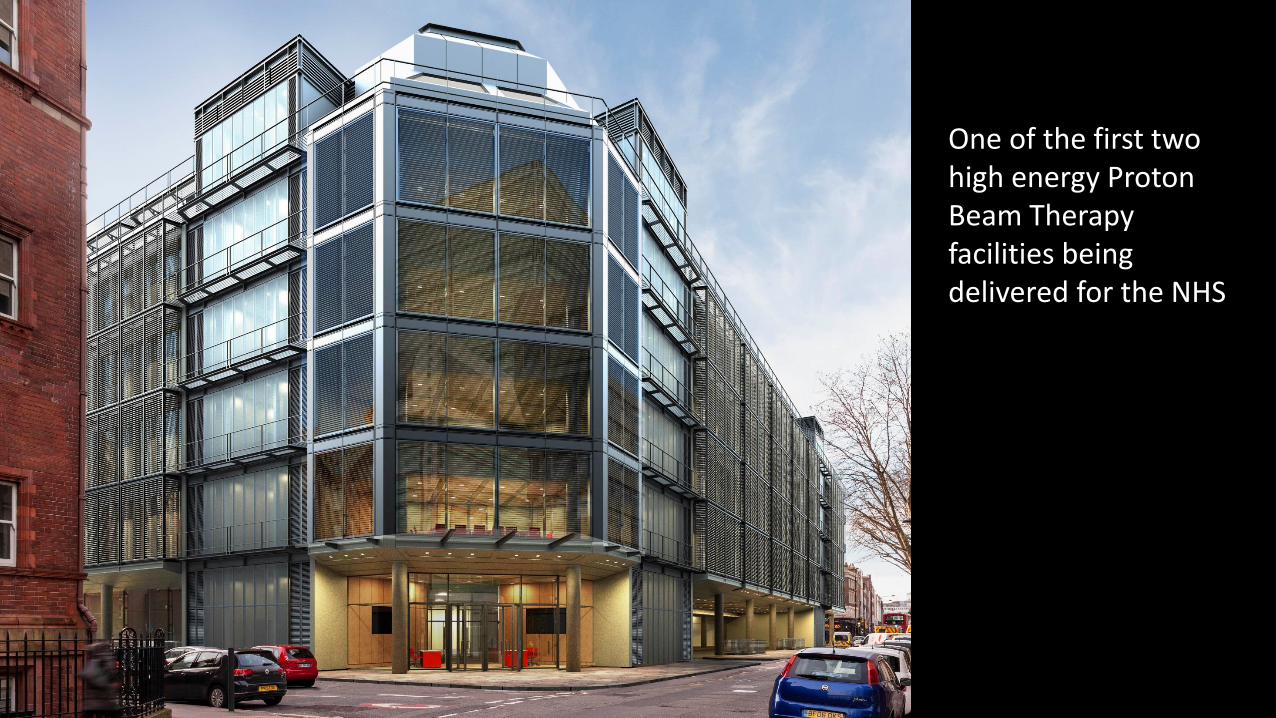
One of the first two high energy Proton Beam Therapy facilities being delivered for the NHS

Going underground• Land scarcity and value in London’s
West End
• Proton Beam Therapy unit below ground
• New Day Surgery unit with eight surgery theatres also below ground
• Modern purpose-built in-patient facility above ground (105 beds) and Europe’s largest centre for the treatment of blood disorders
• Private patient unit at levels 4 and 5
Page 5 of xx
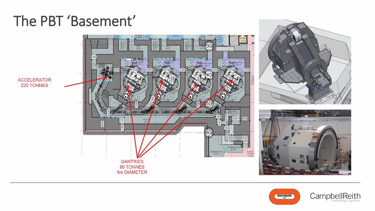
The PBT ‘Basement’
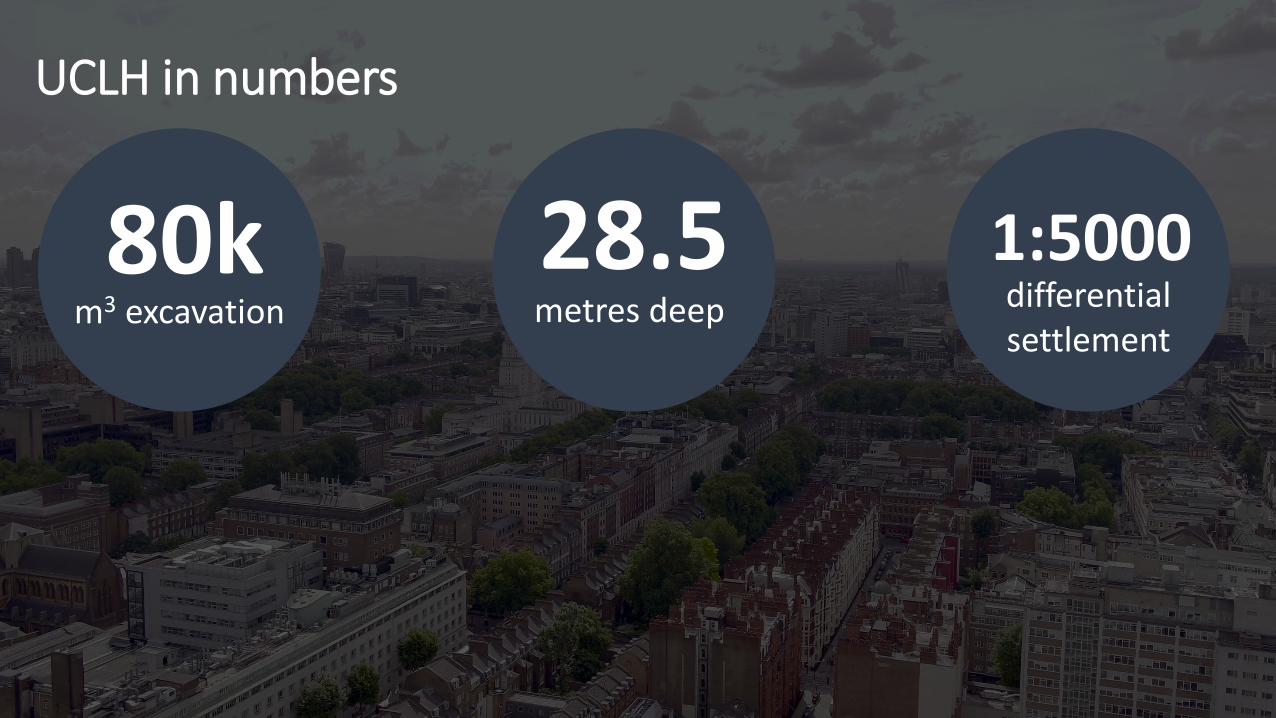
UCLH in numbers
80km3 excavation
28.5metres deep
1:5000differential settlement

Description of Geotechnical Aspects of the Project;
1. Benefits from the site investigation2. Sources of ground movement 3. Impact assessment studies4. Considering both temporary and permanent works5. Ensuring compatibility of all construction processes6. Predicted v measured prop loads

Page 8 of xx
Phase 1
• Two previous GIs on the site, incl 2 BHs to 45m through LC, LG, Upnor Fm, TS into chalk.
• Some data lost, but GIs showed marked difference in depth to base of London Clay across the site - c 4m over c25m
• Further research revealed fault identified during construction of Macmillan Cancer Centre to south. Also LG contains significant laterally variable sand layers
• Intrusive investigation designed to target these.
Phase 2
• 4 BHs to investigate potential faulted zone incl 1 no triple barrel rotary cored hole for high quality samples to allow small strain testing
• BHs clearly showed fault with base of LC 4m shallower in SW than in majority of site
• One BH passed through faulted zone – numerous water strikes (5 no in LC and LG incl one under 20m head of subartesian pressure).
• Series of piezometers at various depths allowed piezometric profile to be determined.
Careful desk study research, targeted intrusive investigation and attention to quality of sampling and testing resulted in a well-defined ground model and good quality data for further assessment and effective design.
Site Investigation

Geological fault
• Lambeth Group 5-6 metres shallower beneath south-west of site
• Numerous water strikes (sub-artesian) and sand layers passing through most sensitive part of site
Geology

Page 10 of xx
• Demolition & Removal
• Underpinning
• Excavation
• Temporary Works
• D Wall installation
• Pile installation
• Wall movements
• Propping
• Load transfer between Temporary & Permanent Works
• Long term settlement / uplift
Sources of New Ground Movements

Page 11 of xx
Surrounding structures and infrastructureParamount Court and other buildings
Infrastructure
• Brick sewers >1m diameter on all four sides
• 450 diameter cast iron trunk main
• HPPE water mains on all four sides
• London Underground Northern line
➢ Detailed GMA and damage assessments
➢ Complex geometry – combined varied software outputs and published data
➢ Calculated displacement, compressive, axial and tensile strains, radius of curvature

Page 12 of xx
Proximity of neighbours
Existing deep pile removal on perimeter of excavation
Jeremy Bentham pub and Paramount Court ‘on the edge’ of the excavation
Page 13 of xx
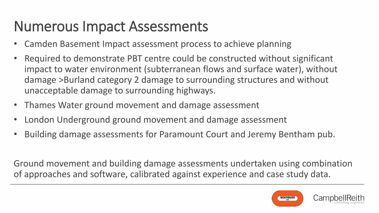
• Camden Basement Impact assessment process to achieve planning
• Required to demonstrate PBT centre could be constructed without significant impact to water environment (subterranean flows and surface water), without damage >Burland category 2 damage to surrounding structures and without unacceptable damage to surrounding highways.
• Thames Water ground movement and damage assessment
• London Underground ground movement and damage assessment
• Building damage assessments for Paramount Court and Jeremy Bentham pub.
Ground movement and building damage assessments undertaken using combination of approaches and software, calibrated against experience and case study data.
Numerous Impact Assessments

Page 14 of xx
Size and plan area of the excavation and unbalanced props loads• Top-down nodes to break-up horizontal
props and restrict movement
• Bespoke CHS to accommodate non-standard dimensions
• King posts plunged into piles to reduce buckling lengths
• Iteration with D-wall design to account for unbalanced loads
• Strutting layer levels set out above raft and intermediate slabs level to make strutting layout independent from permanent structures layout

Page 15 of xx
Predicted v Measured Prop Loads

Average
Predicted v Measured Prop Loads

RD: Real data
A2: A-squared prediction (SLS)
Des: As per design (SLS)
Percent deviation
(+) overestimated
(-) underestimated
RD 1750 kN
A2 2315 kN
Des 2575 kN
RD 1100 kN
A2 2655 kN
Des 4004 kN
RD 1100 kN
A2 4418 kN
Des 4072 kN
RD 4500 kN
A2 5481 kN
Des 4481 kN
RD 2800 kN
A2 3225 kN
Des 2070 kN
RD 2200 kN
A2 3261 kN
Des 3907 kN
32%
47%
22%
0%
15%
-26%
48%
78%
141%
264%
302%
270%15%
-26%
LEVEL 1
Predicted v Measured Prop Loads

RD 4100 kN
A2 5289 kN
Des 3790 kN
RD 8000 kN
A2 9111 kN
Des 6305 kN
RD 7500 kN
A2 12548 kN
Des 8710 kN
RD 11000 kN
A2 17919 kN
Des 14164 kN
RD 7000 kN
A2 13333 kN
Des 6911 kN
RD 5000 kN
A2 14800 kN
Des 9639 kN
29%
-8%
63%
29%
14%
-21%
67%
16%
90%
-1%
196%
93%
RD: Real data
A2: A-squared prediction (SLS)
Des: As per design (SLS)
Percent deviation
(+) overestimated
(-) underestimated15%
-26%
LEVEL 2
Predicted v Measured Prop Loads
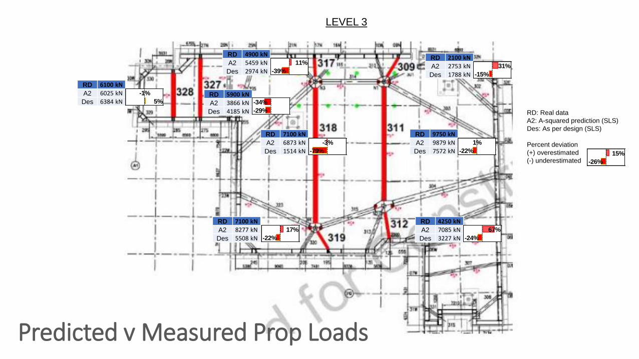
RD 2100 kN
A2 2753 kN
Des 1788 kN
RD 4900 kN
A2 5459 kN
Des 2974 kN
RD 7100 kN
A2 6873 kN
Des 1514 kN
RD 9750 kN
A2 9879 kN
Des 7572 kN
RD 4250 kN
A2 7085 kN
Des 3227 kN
RD 7100 kN
A2 8277 kN
Des 5508 kN
31%
-15%
1%
-22%
67%
-24%
11%
-39%
-3%
-79%
17%
-22%
RD 6100 kN
A2 6025 kN
Des 6384 kNRD 5900 kN
A2 3866 kN
Des 4185 kN
-1%
5% -34%
-29% RD: Real data
A2: A-squared prediction (SLS)
Des: As per design (SLS)
Percent deviation
(+) overestimated
(-) underestimated15%
-26%
LEVEL 3
Predicted v Measured Prop Loads

Page 20 of xx
The value added by developing underground
Significant geotechnical and location challenges overcome
Efficient and collaborative delivery generating value and quality
Outstanding engagement with local and engineering communities and other stakeholders
Geotechnical Engineers have an important role to play
Summary

UCLH PROTON BEAM THERAPY CENTRE
Leveraging the benefits of geotechnical software and modelling


