Albert M. K. Cheng Outline Embedded Real-Time Systems Functional Reactive Systems (FRS) Cyber-Physical Systems (CPS) Haskell and Functional Reactive Programming (FRP) Priority-based FRP (P-FRP) Response time analysis Power-aware scheduling * Supported in part by the National Science Foundation under Awards No. 0720856 and No. 1219082. Faculty Seminar Functional Reactive Programming and Response Time Analysis for Developing Embedded/Real-Time and Cyber-Physical Systems
Transcript
Albert M. K. Cheng
�Outline
� Embedded Real-Time Systems
� Functional Reactive Systems (FRS)
� Cyber-Physical Systems (CPS)
� Haskell and Functional Reactive Programming (FRP)
� Priority-based FRP (P-FRP)
� Response time analysis
� Power-aware scheduling
* Supported in part by the National Science Foundation under Awards No. 0720856 and No. 1219082.
Faculty Seminar
Functional Reactive Programming and Response Time Analysis for Developing Embedded/Real-Time and Cyber-Physical Systems
Real-Time Systems Group
• Director
Prof. Albert M. K. Cheng
• PhD students
Yong Woon Ahn, Yu Li, Xingliang Zou,
Behnaz Sanati, Sergio Chacon, Zeinab
Kazemi, Chaitanya Belwal (just graduated)
• MS students
Daxiao Liu, Yuanfeng Wen (just graduated),
Fang Liu (just graduated)
• Undergraduate students (NSF-REU)
Mozahid Haque, Kaleb Christoffersen,
Dylan Thompson (just completed), James
Hyatt (just completed)
• Visiting scholars
Yu Jiang, Heilongjiang University, Harbin,
China; Qiang Zhou (arriving in November
2013), Beihang University, Beijing, China
2 / 119
Yu Li (Best Junior PhD Student Awardee and Friends of NSM Graduate Fellow) and Prof. Albert Cheng visit the NSF-sponsored Arecibo Observatory (world's largest and most sensitive radiotelescope) in Arecibo, Puerto Rico, after their presentation at the flagship RTSS 2012.
Real-time systems research group at Yuanfeng Wen’s graduation party in May 2013.
Faculty Seminar
Real-Time Systems Theory
3 / 119
Pathfinder mission to Mars: best known Priority Inversion problem.Failure to turn on priority Inheritance (PI) - Most PI schemes complicate and slow down
the locking code, and often are used to compensate for poor application designs.http://research.microsoft.com/en-us/um/people/mbj/mars_pathfinder/mars_pathfinder.html
Real-Time Systems Theory
4 / 119
• The more components a real-time system
has, the more difficult it is to build and
maintain.
– In such systems, preemptive scheduling may not be suitable, since it is likely to create runtime overheads which can result in worst-case task execution times of up to 40% greater than fully non-preemptive execution.
• Yao G., Buttazzo G., Bertogna M., "Feasibility analysis underfixed priority scheduling with limited preemptions," Real-TimeSystems, Volume 47 Issue 3, pages: 198-223, May 2011.
Real-Time Systems Theory
5 / 119
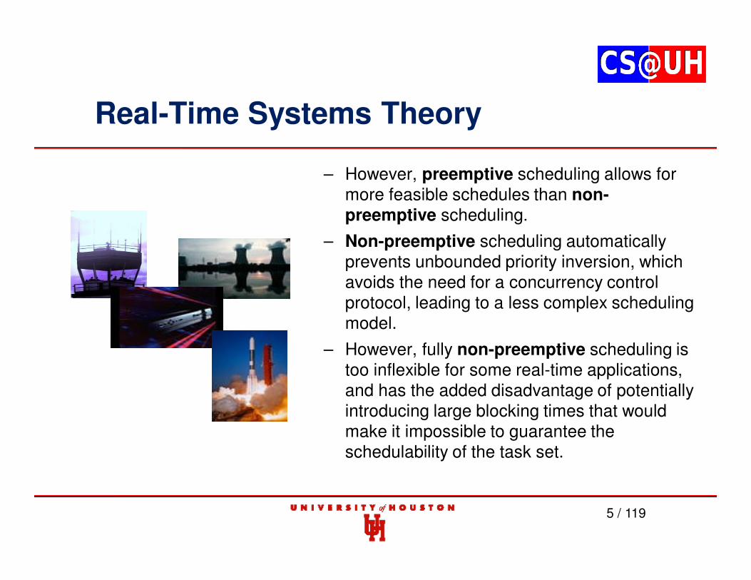
– However, preemptive scheduling allows for more feasible schedules than non-preemptive scheduling.
– Non-preemptive scheduling automatically prevents unbounded priority inversion, which avoids the need for a concurrency control protocol, leading to a less complex scheduling model.
– However, fully non-preemptive scheduling is too inflexible for some real-time applications, and has the added disadvantage of potentially introducing large blocking times that would make it impossible to guarantee the schedulability of the task set.
Real-Time Systems Theory
6 / 119
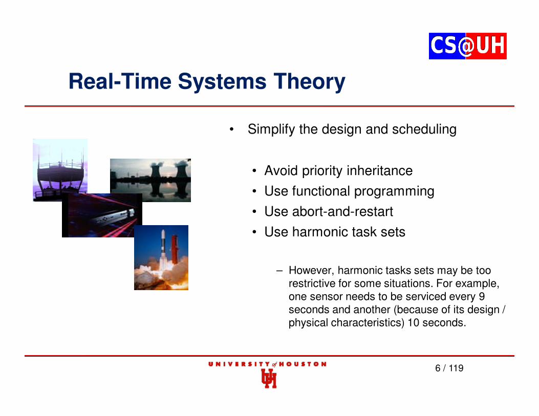
• Simplify the design and scheduling
• Avoid priority inheritance
• Use functional programming
• Use abort-and-restart
• Use harmonic task sets
– However, harmonic tasks sets may be too restrictive for some situations. For example, one sensor needs to be serviced every 9seconds and another (because of its design / physical characteristics) 10 seconds.
Real-Time Systems Theory
7 / 119
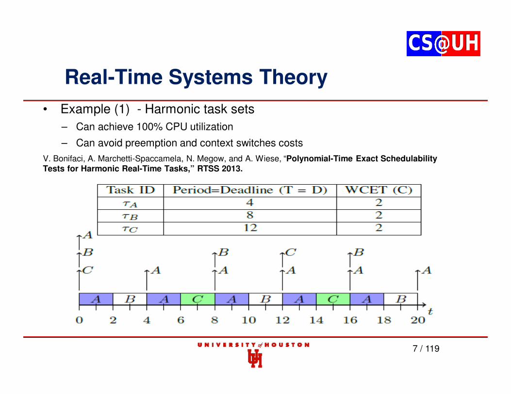
• Example (1) - Harmonic task sets
– Can achieve 100% CPU utilization
– Can avoid preemption and context switches costs
V. Bonifaci, A. Marchetti-Spaccamela, N. Megow, and A. Wiese, “Polynomial-Time Exact SchedulabilityTests for Harmonic Real-Time Tasks,” RTSS 2013.
Real-Time Systems Theory
8 / 119
• Example (2) - Harmonic task sets
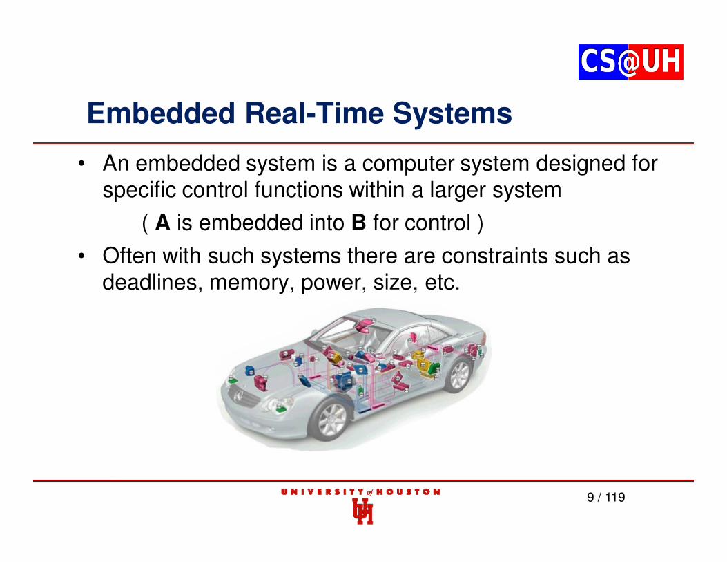
Embedded Real-Time Systems
• An embedded system is a computer system designed for specific control functions within a larger system
( A is embedded into B for control )
• Often with such systems there are constraints such as deadlines, memory, power, size, etc.
9 / 119
Embedded Real-Time Systems
• Real-time systems (RTS) are reactive systems that are required to respond to an environment in a bounded amountof time.
• Functional reactive systems (FRS)
• Cyber-physical systems (CPS)
– Challenges
• Complexity
• Reliability
– Fault-tolerant design
– Meeting deadlines (Response Time Analysis (RTA))
• Security/Privacy
10 / 119
Functional Reactive Systems (FRS)
Systems that react to the environment being monitored andcontrolled in a timely fashion using functional (reactive)programming are known as Functional Reactive Systems(FRS).
These systems can range from small devices (which are nota CPS) to distributed and complex components (similar to aCPS).
11 / 119
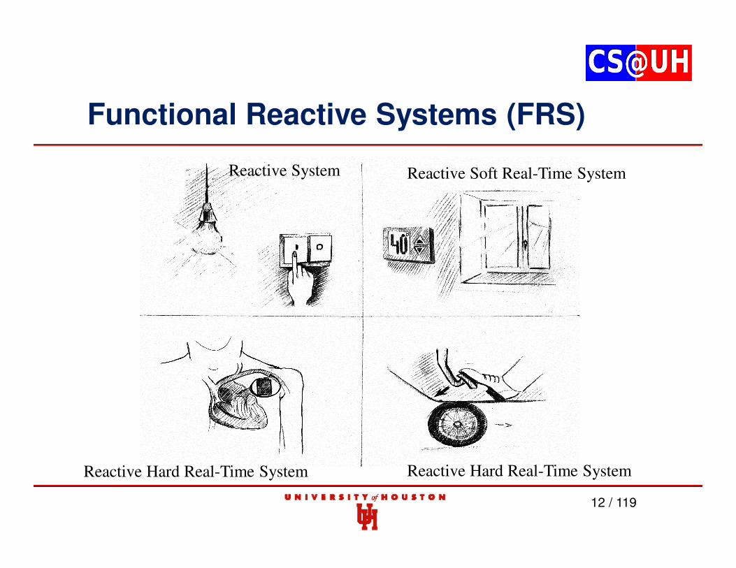
Functional Reactive Systems (FRS)
12 / 119
Reactive System Reactive Soft Real-Time System
Reactive Hard Real-Time System Reactive Hard Real-Time System
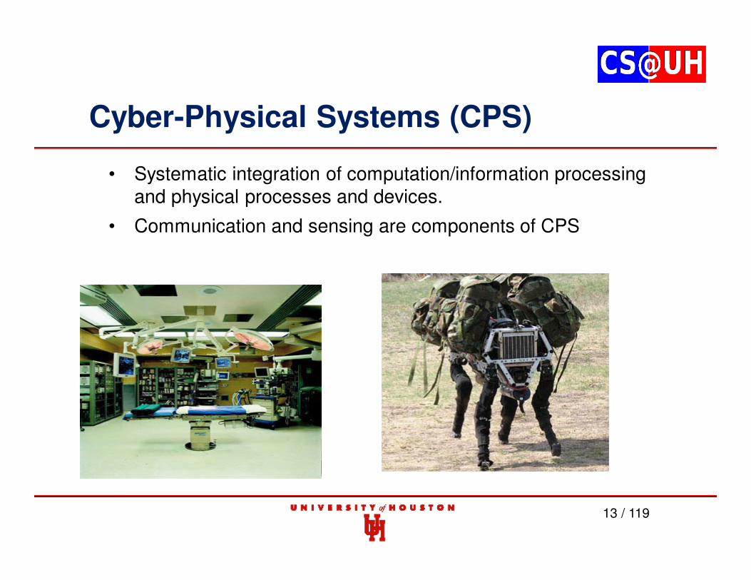
Cyber-Physical Systems (CPS)
13 / 119
• Systematic integration of computation/information processing and physical processes and devices.
• Communication and sensing are components of CPS
Cyber-Physical Systems (CPS)
The current set of tools available for analysis cannot handlethe complexity of CPS and thus are unable to predictsystem behavior with high degree of accuracy.
The consequences of these shortcomings:
Consider the electric power grid -- Massive failures leadingto blackouts can be triggered by minor events.
14 / 119
Cyber-Physical Systems (CPS)
15 / 119
Classic (non-CPS) electric grid system/behavior
Cyber-Physical Systems (CPS)
16 / 119
• In a CPS, wireless/wired smart meters measuring real-time electricityusage and historical data (state) feedback (communication) to thegeneration station to better manage and distribute electricity.
• Current and predicted weather condition data can also further informthe decision-making in where to distribute electricity (very hot or verycold weather increase electricity demand).
• There is also a need to guard against intrusion into the system.
• Advocate formal verification to ensure satisfaction of safety properties.
Cyber-Physical Systems (CPS)
17 / 119
Cyber-Physical Systems (CPS)
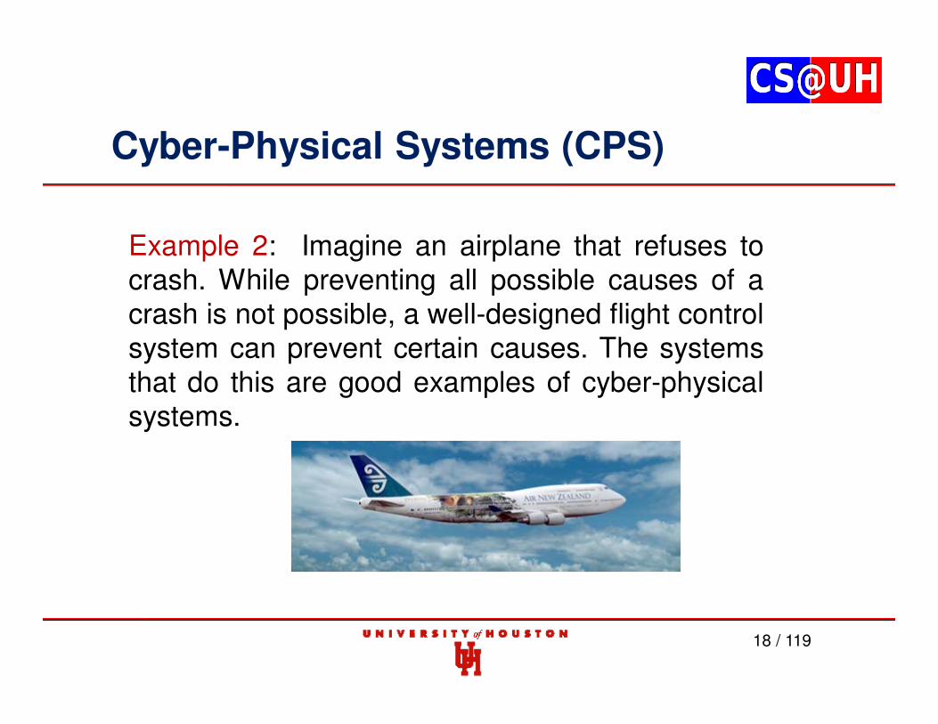
Example 2: Imagine an airplane that refuses tocrash. While preventing all possible causes of acrash is not possible, a well-designed flight controlsystem can prevent certain causes. The systemsthat do this are good examples of cyber-physicalsystems.
18 / 119
Cyber-Physical Systems (CPS)
For example, some airplanes use a technique called flight envelopeprotection to prevent a plane from going outside its safe operating range,and prevent a pilot from causing a stall.
19 / 119
Cyber-Physical Systems (CPS)
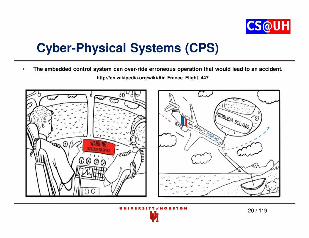
• The embedded control system can over-ride erroneous operation that would lead to an accident.
• The concept of flight envelope protection could beextended to prevent other causes of crashes. Forexample, the soft walls system proposed by Prof. EdwardLee, if implemented, would track the location of theaircraft on which it is installed and prevent it from flyinginto obstacles such as mountains.
– E. A. Lee, "Soft Walls - Modifying Flight Control Systems to Limit the Flight Spaceof Commercial Aircraft," EECS Department, University of California, Berkeley,Tech. Rep. UCB/ERL M01/31, 2001.
21 / 119
Cyber-Physical Systems (CPS)
22 / 119
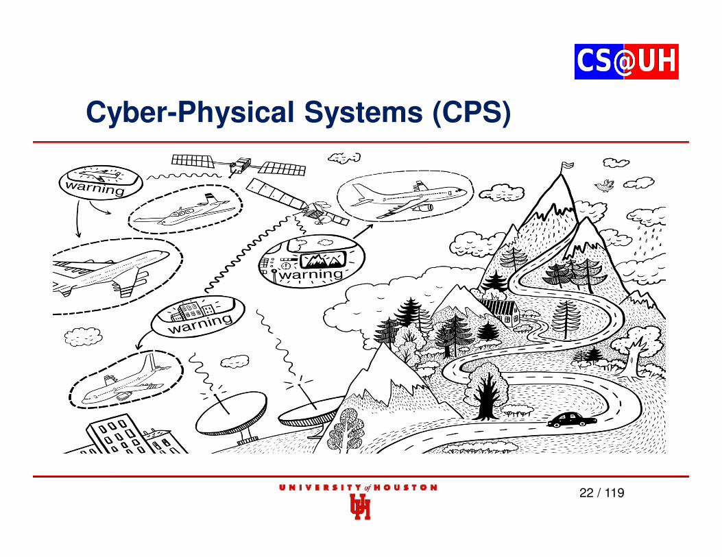
Cyber-Physical Systems (CPS)
23 / 119
• One of the key goals in our research is to develop the core tools thatcan be used to facilitate the analysis, design and engineering ofhighly-complex systems.
• With such tools, we can ensure that these systems are reliable,predictable, efficient, secure and resilient to multiple points of failure,and hence that their operation and safety can be depended uponwith a high degree of confidence.
• We advocate formal verification to ensure safety of CPS's, but theircomplexity requires further research in verification tools.
Cyber-Physical Systems (CPS)
24 / 119
Small Aircraft Transportation System (SATS)
Self Control Area Airspace Volume
Cyber-Physical Systems (CPS)
25 / 119
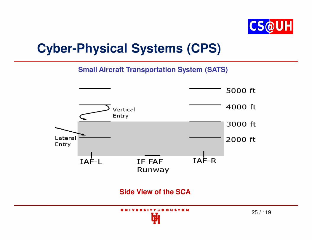
Small Aircraft Transportation System (SATS)
Side View of the SCA
Cyber-Physical Systems (CPS)
26 / 119
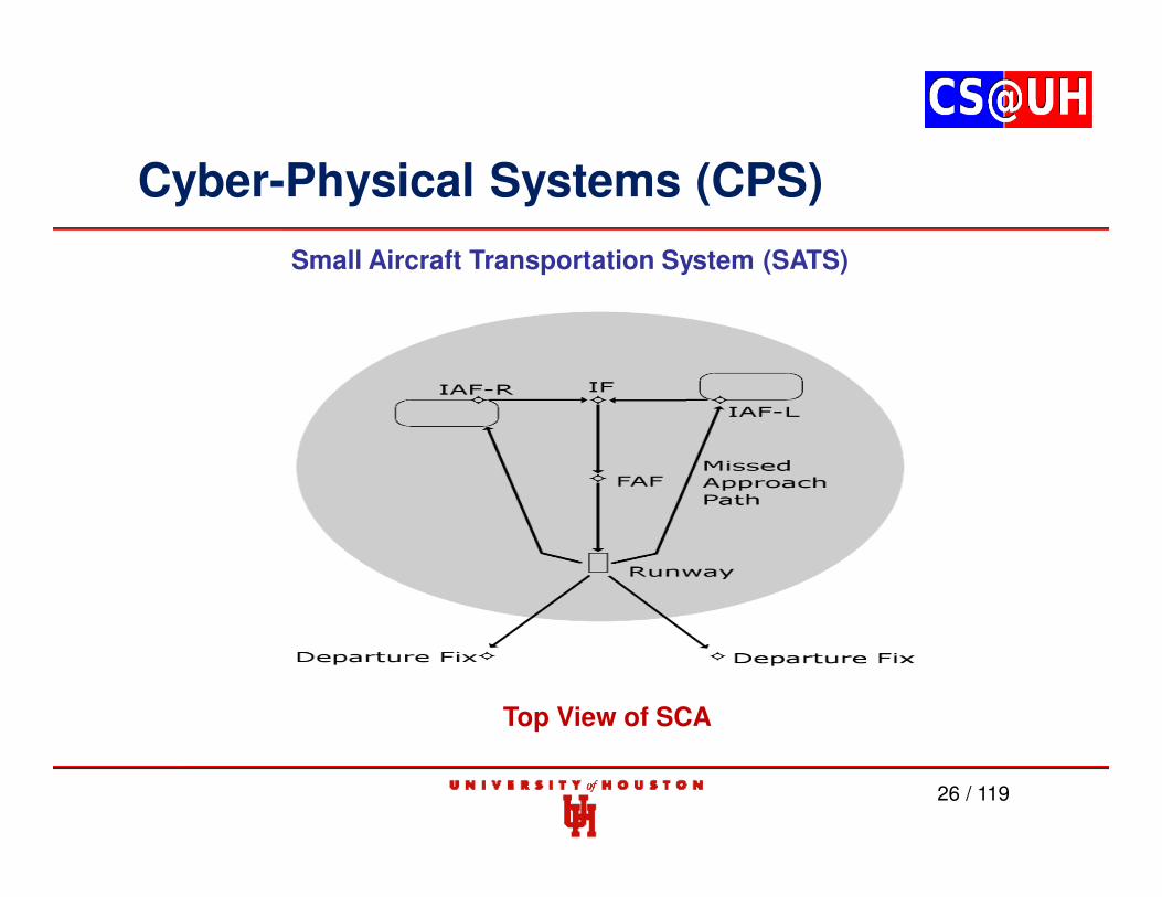
Small Aircraft Transportation System (SATS)
Top View of SCA
Cyber-Physical Systems (CPS)
27 / 119
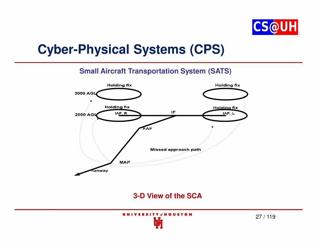
Small Aircraft Transportation System (SATS)
3-D View of the SCA
Cyber-Physical Systems (CPS)
28 / 119
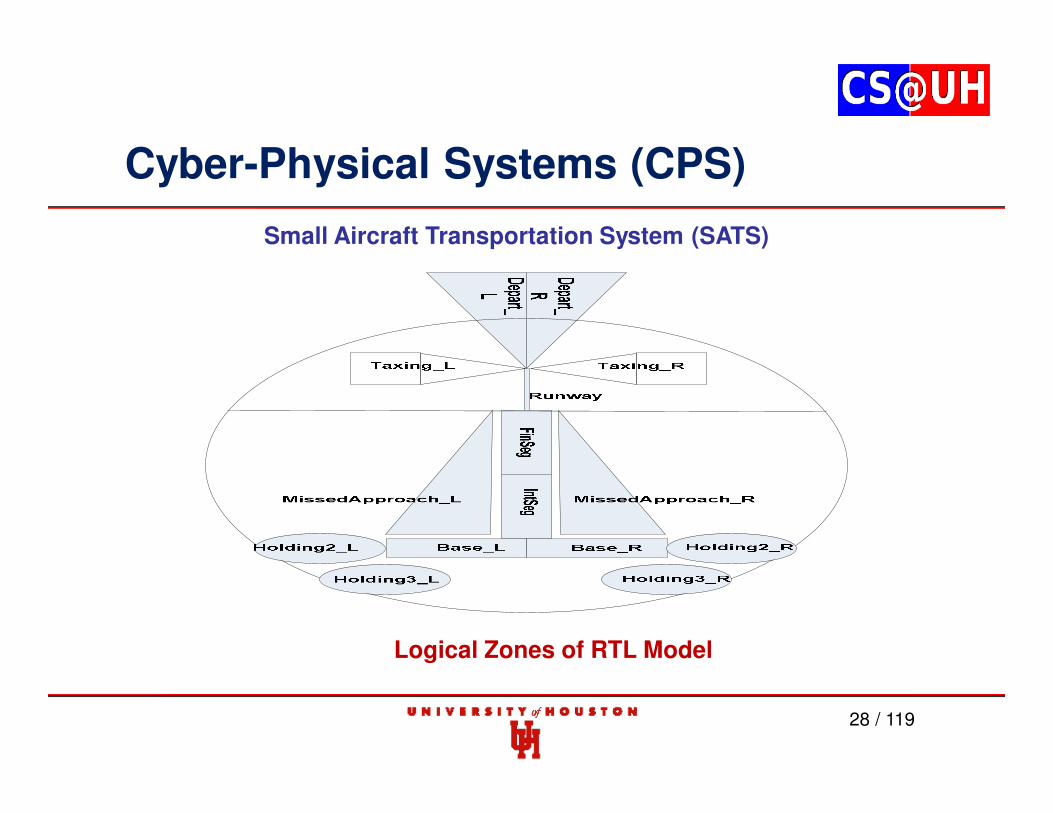
Small Aircraft Transportation System (SATS)
Logical Zones of RTL Model
Cyber-Physical Systems (CPS)
29 / 119
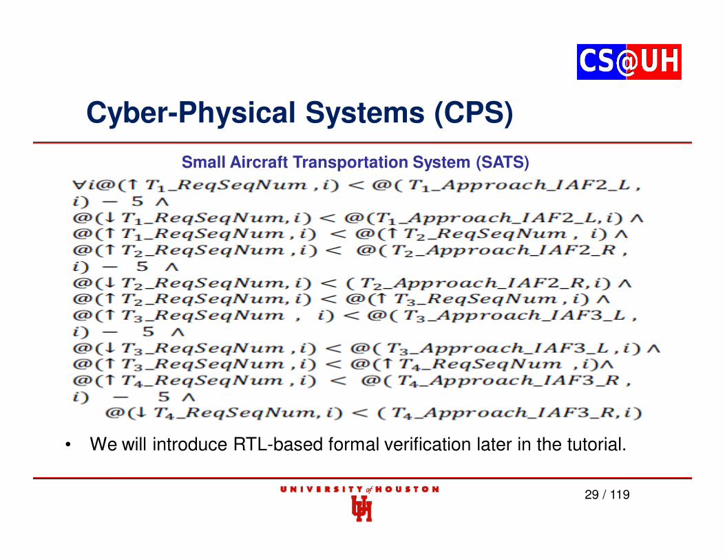
• We will introduce RTL-based formal verification later in the tutorial.
• P-FRP provides real-time guarantees using static priority assignment
• Higher-priority tasks preempt lower-priority ones; preempted tasks are aborted
• Multi-version commit model of execution
• Atomic execution – “all or nothing” proposition
• Execution different from ‘standard’ models
Other Examples of Functional Programming (FP) Languages:
• Haskell
• Atom - Domain Specific Language in Haskell
• Erlang - Developed at Ericsson for programming telecommunication equipment
• Esterel - Designed for reactive programming
• F# - Developed by Microsoft; available as a commercial platform
30 / 119
The Haskell Functional Programming Language
31 / 119
- The GHC compiler/interpreter uses a round-robin scheduler for Haskell threads - No thread priorities yet for forkIO threads in GHC
A simple ABS example in Haskell:
import Control.Concurrent -- For threading facilities: “forkIO”, “newEmptyMVar”, “takeMVar”, and “putMVar”.import Control.Monad (forever) -- For "forever"
-- Type aliases help keep track of what values we are talking about.
type WheelSpeed = Double -- A "double" floating point valuetype AverageSpeed = Double
-- | The ABS can either forcibly release, focibly engage, or stay neutral for each wheel.-- The deriving clause creates the obvious Show instance for this ADT.
data BrakeSignal = Release | Engage | Neutral
deriving Show
32 / 119
-- | Compute the average speed by dividing the sum of the list of speeds by the length.-- fromIntegral is there to convert the result of length (Int) into a Double-- Note, this will traverse the list twice, ineffcient for vehicles with millions of wheels.averageSpeed :: [WheelSpeed] -> AverageSpeedaverageSpeed speeds = sum speeds / (fromIntegral $ length speeds)
-- | This algorithm may be much more complicated, but the basic idea is present.-- Given the average speed and a particular wheel speed, check to see if we are-- within 5 (mph, kph, m/s, whatever) of the average. If we are below the minimum-- send the release signal to the brakes. If we are within 5, remain neutral, otherwise-- send a signal to engage the brakes.ecuHelper :: AverageSpeed -> WheelSpeed -> BrakeSignalecuHelper average speed | speed < min = Release
| speed < max = Neutral| otherwise = Engage
wheremin = average - 5max = average + 5
The Haskell Programming Language
33 / 119
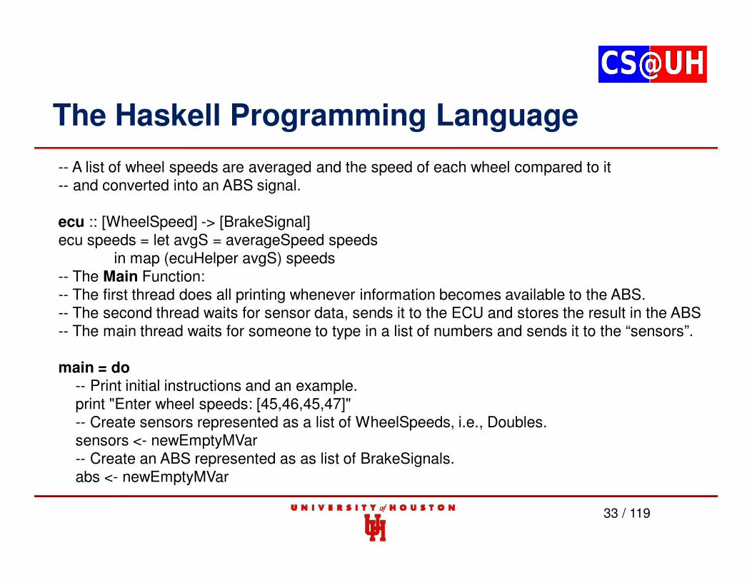
-- A list of wheel speeds are averaged and the speed of each wheel compared to it-- and converted into an ABS signal.
in map (ecuHelper avgS) speeds-- The Main Function:-- The first thread does all printing whenever information becomes available to the ABS.-- The second thread waits for sensor data, sends it to the ECU and stores the result in the ABS-- The main thread waits for someone to type in a list of numbers and sends it to the “sensors”.
main = do-- Print initial instructions and an example.print "Enter wheel speeds: [45,46,45,47]"-- Create sensors represented as a list of WheelSpeeds, i.e., Doubles.sensors <- newEmptyMVar-- Create an ABS represented as as list of BrakeSignals.abs <- newEmptyMVar
The Haskell Programming Language
34 / 119
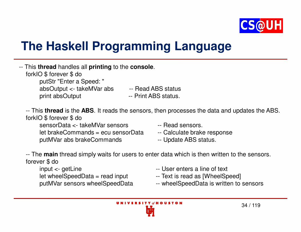
-- This thread handles all printing to the console.forkIO $ forever $ do
-- The main thread simply waits for users to enter data which is then written to the sensors.forever $ do
input <- getLine -- User enters a line of textlet wheelSpeedData = read input -- Text is read as [WheelSpeed]putMVar sensors wheelSpeedData -- wheelSpeedData is written to sensors
The Haskell Programming Language
35 / 119
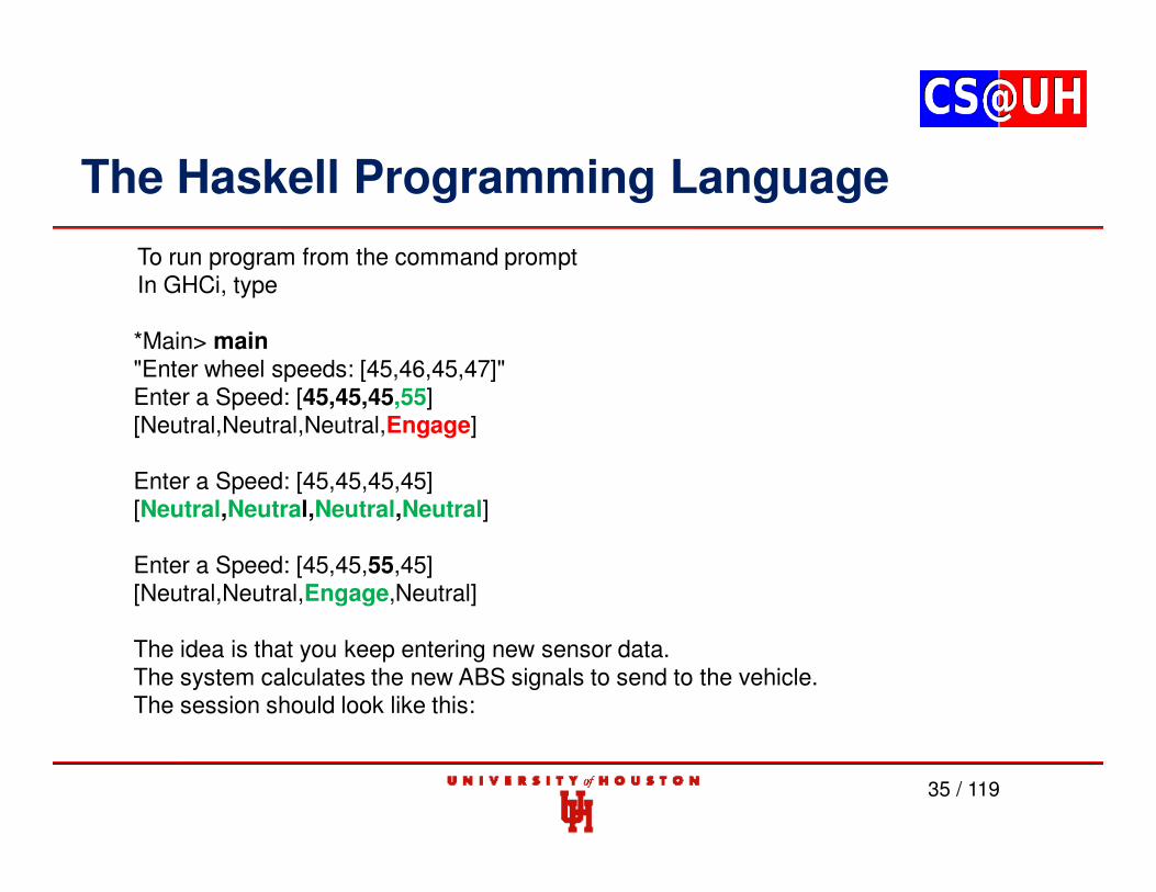
To run program from the command promptIn GHCi, type
*Main> main"Enter wheel speeds: [45,46,45,47]"Enter a Speed: [45,45,45,55][Neutral,Neutral,Neutral,Engage]
Enter a Speed: [45,45,45,45][Neutral,Neutral,Neutral,Neutral]
Enter a Speed: [45,45,55,45][Neutral,Neutral,Engage,Neutral]
The idea is that you keep entering new sensor data. The system calculates the new ABS signals to send to the vehicle. The session should look like this:
The Haskell Programming Language
36 / 119
C# and F#
Execution Time (ns.)
37 / 119
C# and F#
C# : 10,000 Iterations F# : 10,000 Iterations
Functional Reactive Programming (FRP)
38 / 119
• Functional reactive programming (FRP) is a style of functionalprogramming where programs are inherently stateful, butautomatically react to changes in state.
• FRP allows intuitive specification and formal verification of safety-critical behaviors, thus reducing the number of defects during thedesign phase, and the stateless nature of execution avoids the needfor complex programming involving synchronization primitives.
• Therefore, the program remains an algebraic description of systemstate, with the task of keeping the stated (unidirectional) relationshipsin sync left to the *language*.
39 / 119
• FRP is essentially (though rarely acknowledged as such) anextension to the old idea of dataflow programming.
• A key difference is that FRP supports higher-order functions, andmodern FRP systems are generally well-integrated into broaderlanguages.
• The original (modern) FRP work was built in the context of Haskell,though major FRP systems have also been built atop many otherlanguages.
Functional Reactive Programming (FRP)
40 / 119
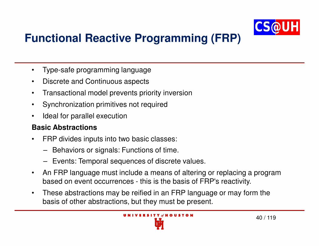
• Type-safe programming language
• Discrete and Continuous aspects
• Transactional model prevents priority inversion
• Synchronization primitives not required
• Ideal for parallel execution
Basic Abstractions
• FRP divides inputs into two basic classes:
– Behaviors or signals: Functions of time.
– Events: Temporal sequences of discrete values.
• An FRP language must include a means of altering or replacing a program based on event occurrences - this is the basis of FRP's reactivity.
• These abstractions may be reified in an FRP language or may form the basis of other abstractions, but they must be present.
Functional Reactive Programming (FRP)
41 / 119
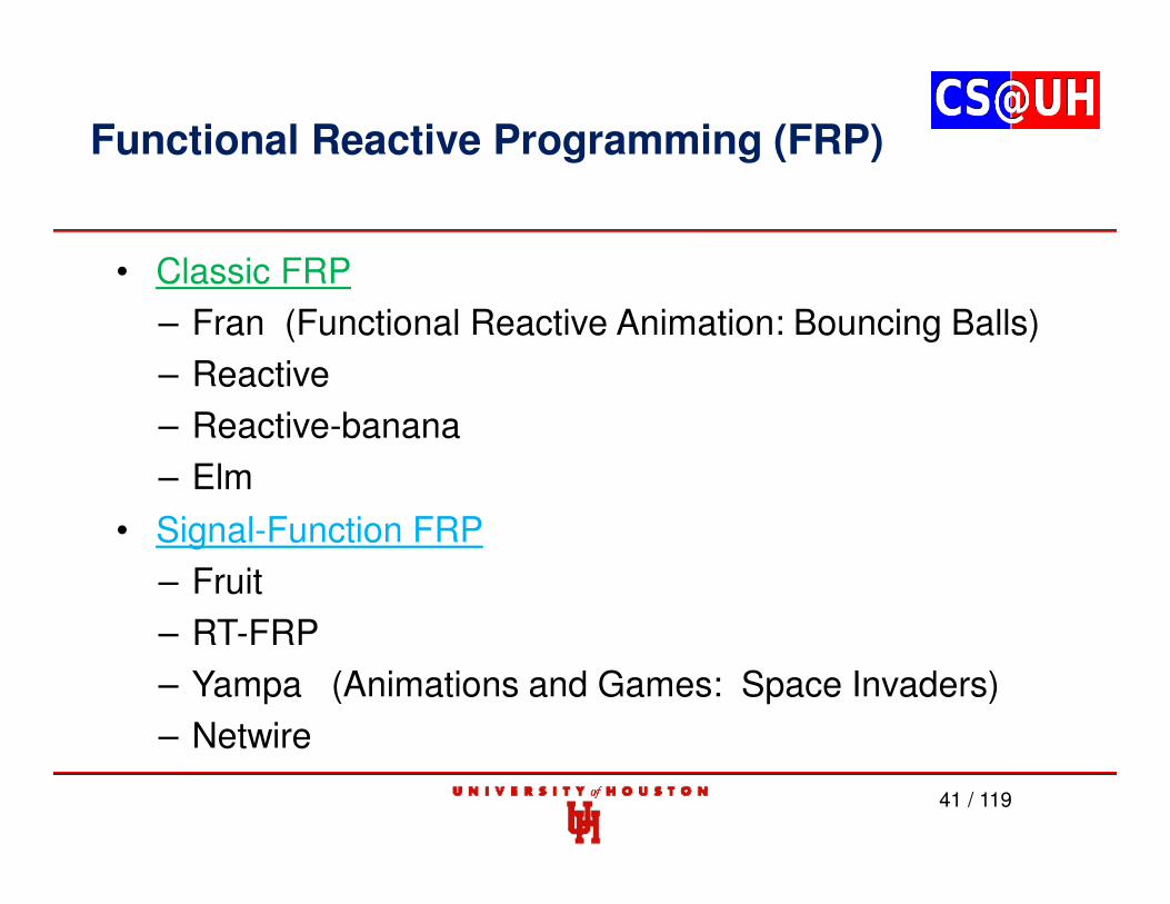
• Classic FRP
– Fran (Functional Reactive Animation: Bouncing Balls)
– Reactive
– Reactive-banana
– Elm
• Signal-Function FRP
– Fruit
– RT-FRP
– Yampa (Animations and Games: Space Invaders)
– Netwire
Functional Reactive Programming (FRP)
42 / 119
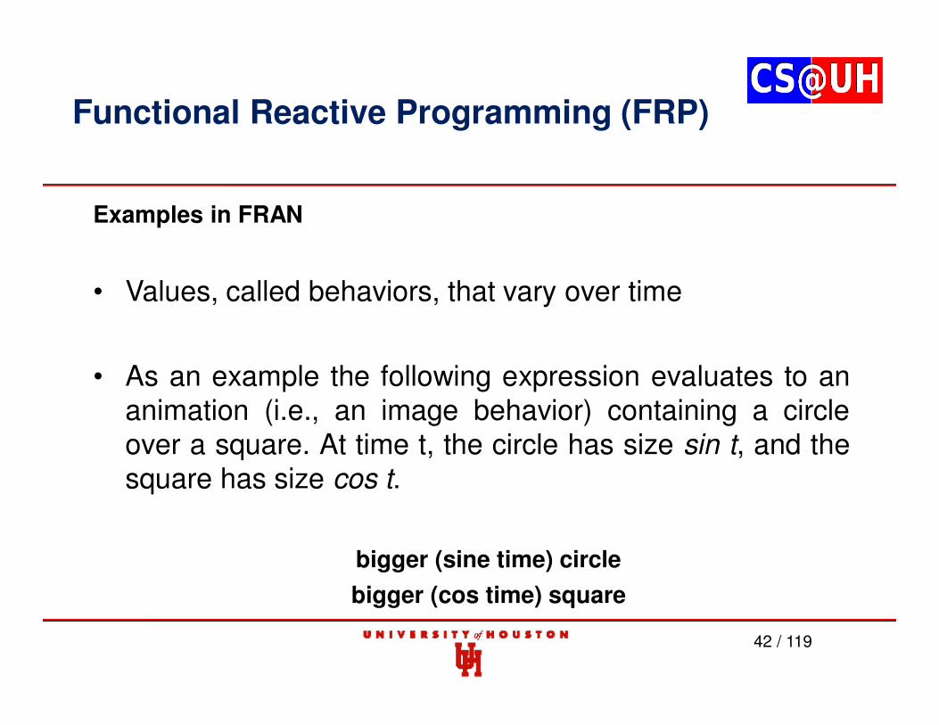
Examples in FRAN
• Values, called behaviors, that vary over time
• As an example the following expression evaluates to ananimation (i.e., an image behavior) containing a circleover a square. At time t, the circle has size sin t, and thesquare has size cos t.
bigger (sine time) circle
bigger (cos time) square
Functional Reactive Programming (FRP)
43 / 119
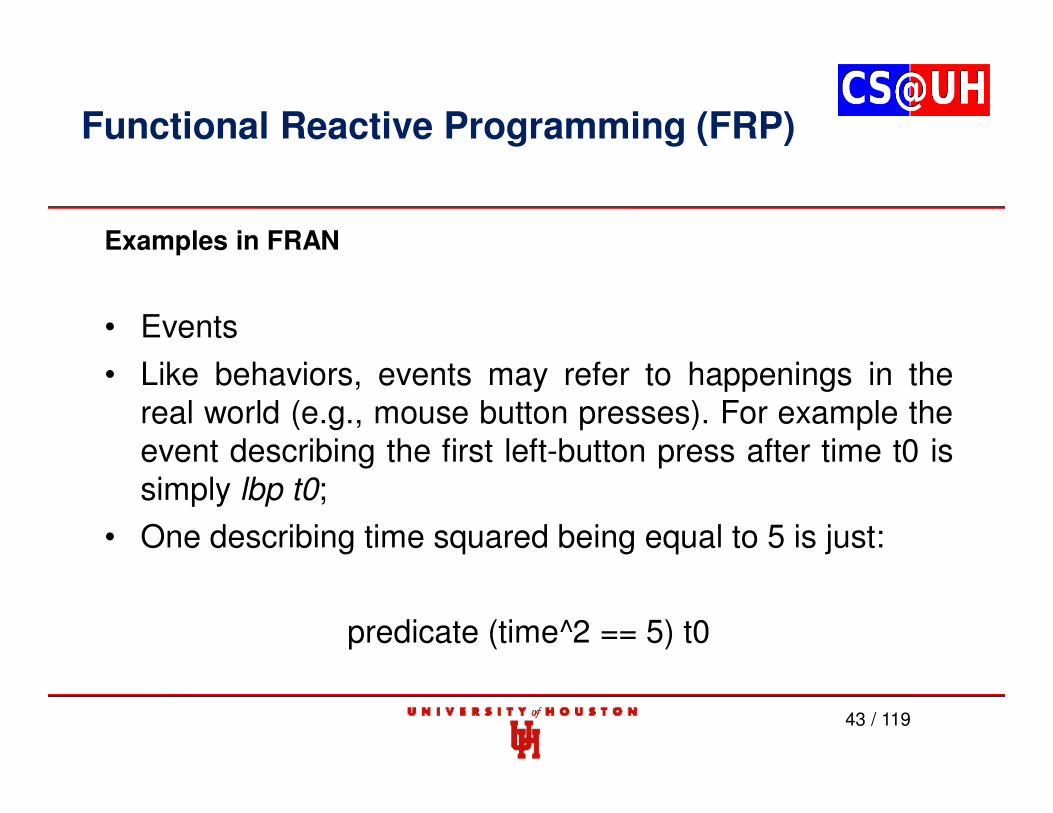
Examples in FRAN
• Events
• Like behaviors, events may refer to happenings in thereal world (e.g., mouse button presses). For example theevent describing the first left-button press after time t0 issimply lbp t0;
• One describing time squared being equal to 5 is just:
predicate (time^2 == 5) t0
Functional Reactive Programming (FRP)
44 / 119
Examples in FRAN
• Many behaviors are expressed in terms of reactions to events. Buteven these reactive behaviors have declarative semantics in terms oftemporal composition.
• For example, a color-valued behavior that changes from red togreen with each button press can be described by the followingsimple recurrence:
colorCycle t0 =
red 'untilB' lbp t0 *=> \t1 ->
green 'untilb' lbp t1 *=> \t2 ->
colorCycle t2
Functional Reactive Programming (FRP)
45 / 119
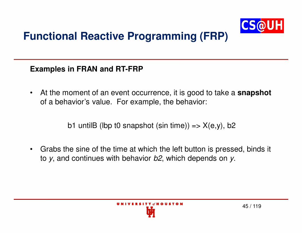
Examples in FRAN and RT-FRP
• At the moment of an event occurrence, it is good to take a snapshot
• FRP is still relatively new and the design space is still beingexplored.
• Strengths
• FRP makes writing reactive programs easier to reason about and toavoid common errors
• It is easier to expand and create new behaviors. Once the programbecomes more complex, forkIO and multiple threads might startinterfering with each other, or there would be odd interleaving,blocking, or other bad concurrency behavior.
FRP is still Haskell. It is just a different style.
Functional Reactive Programming (FRP)
52 / 119
• Using FRP makes the controllers (the computational components of CPS)more amenable to analysis and verification.
• We can treat components (programed in FRP) as mathematical functions,which can be composed and synthesized to form a much larger, complexsystem.
• More resistant to faults since there are no intermediate states. They can beconnected and composed more easily.
• With procedural programs, there are more uncertainties, for example,intermediate states if faults/interruptions occur that need to bespecified/modeled, making developing a CPS with guaranteed safety andresponse much more complex and potentially intractable.
• In the electric grid example, different generating stations have controlcomponents which analyze real-time data from smart meters, weather data,and industrial plants' energy usage to determine optimal or near-optimalgeneration and distribution of electricity.
Functional Reactive Programming (FRP)
Priority-based FRP (P-FRP)
• P-FRP aims to improve the programming of reactive real-time systems.
– Supports assignment of different priorities to events
– Benefits of using P-FRP over the imperative styles
• P-FRP allows the programmer to intuitively describe safety-critical behaviors of the system, thus lowering the chance ofintroducing bugs in the design phase.
• Its stateless nature of execution does not require the use ofsynchronization primitives like mutexes and semaphores, thusreducing the complexity in programming.
53 / 119
54 / 119
Priority-based FRP (P-FRP)
• To preserve data consistency, shared resources must be accessed in mutual exclusion:
55 / 119
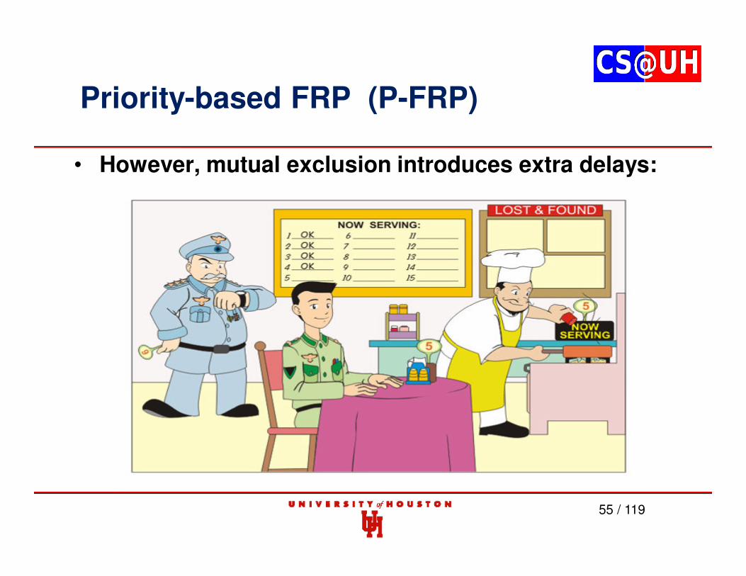
Priority-based FRP (P-FRP)
• However, mutual exclusion introduces extra delays:
Priority-based FRP (P-FRP)
56 / 119
Example: The Car Controller
* C = worst case execution time* T = (sampling) period = D (deadline)
• Speed Measurement: C=4ms, T=20ms, D=20ms
• ABS control: C=10ms,T=40ms, D=40ms
• Fuel injection: C=40ms,T=80ms, D=80ms
• Other software with soft deadlines, audio, air condition, etc.
Try any method to schedule the tasks
Priority-based FRP (P-FRP)
57 / 119
Static cyclic scheduling: + and –
• Deterministic: predictable (+)
• Easy to implement (+)
• Inflexible (-)
– Difficult to modify, e.g., adding another task
– Difficult to handle external events
• The table can be huge (-)
– Huge memory-usage
– Difficult to construct the time table
Priority-based FRP (P-FRP)
58 / 119
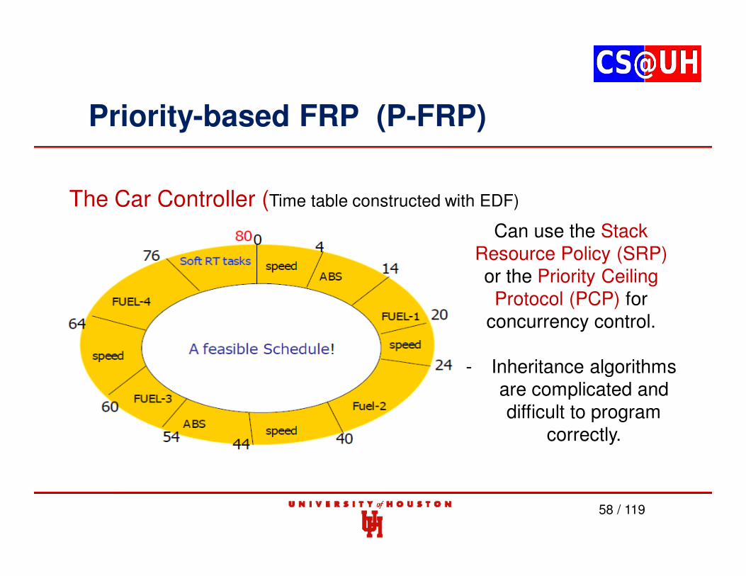
The Car Controller (Time table constructed with EDF)
Can use the Stack Resource Policy (SRP) or the Priority Ceiling Protocol (PCP) for
concurrency control.
- Inheritance algorithms are complicated and difficult to program
correctly.
Priority-based FRP (P-FRP)
• In P-FRP, the scheduling model is called Abort-and-Restart (ANR)
– Copy and restore operations
• To allow for correct restarting of handlers, compilation is
extended to generate statements that store variables
modified in an event handler into fresh temporary (or
scratch) variables in the beginning of the handler while
interrupts are turned off, and to restore variables from the
temporary variables at the end of the handler while
interrupts are turned off.
59 / 119
Priority-based FRP (P-FRP)
60 / 119
Priority-based FRP (P-FRP)
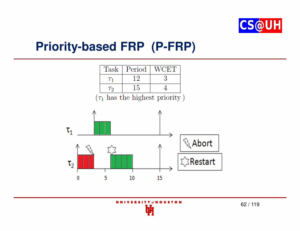
• The Abort-and-Restart (ANR) Scheduling Model
– The idea of the ANR model is that a lower-priority task is abortedwhen a higher priority task arrives into the system. Once the higher-priority task is done, the lower priority task restarts as new.
61 / 119
Priority-based FRP (P-FRP)
62 / 119
Priority-based FRP (P-FRP)
• Advantages of Abort-and-Restart (ANR)
– A simpler programming model
– Tasks execute atomically so no task is blocked by another task
• The priority inversion problem is removed
• No overheads caused by priority inheritance
• Closer adherence to priority scheduling
63 / 119
Priority-based FRP (P-FRP)
64 / 119
Priority-based FRP (P-FRP)
65 / 119
Priority-based FRP (P-FRP)
66 / 119
Priority-based FRP (P-FRP)
67 / 119
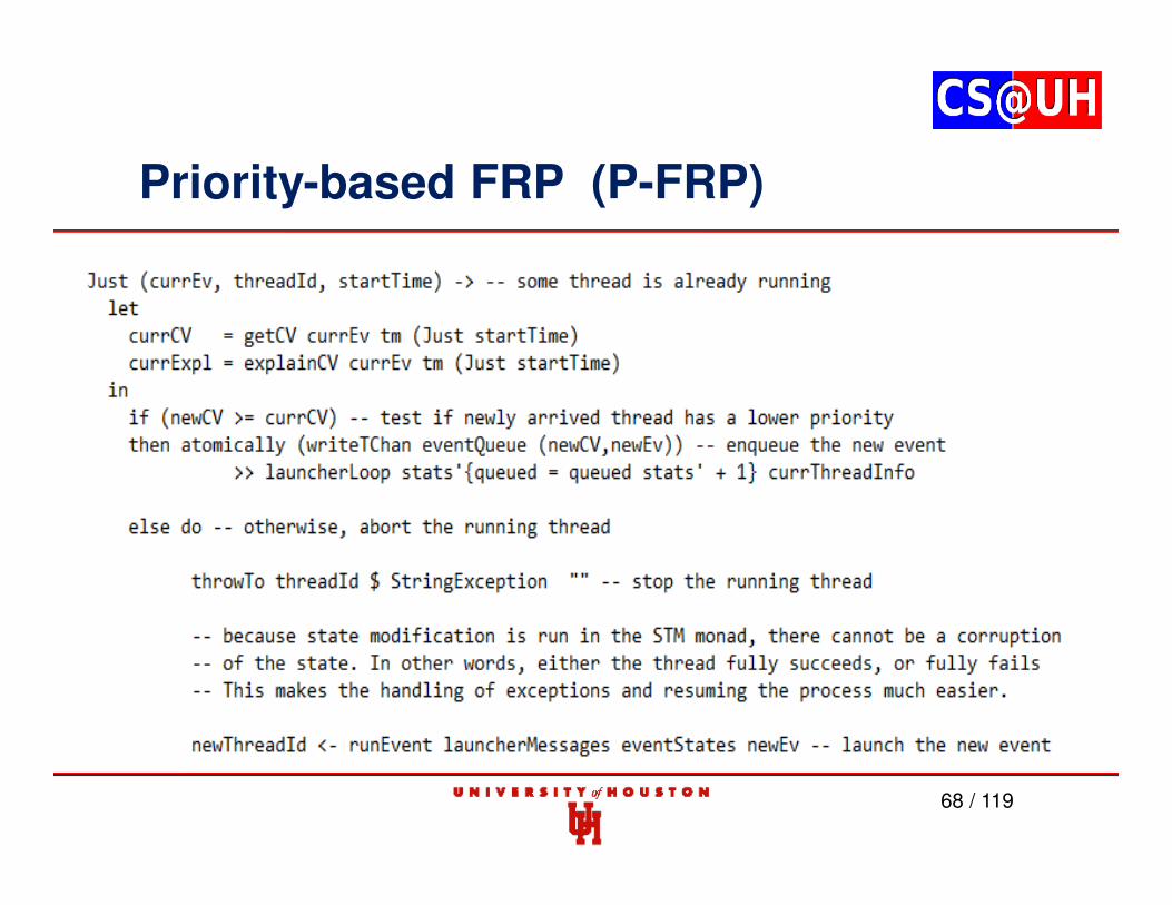
Priority-based FRP (P-FRP)
68 / 119
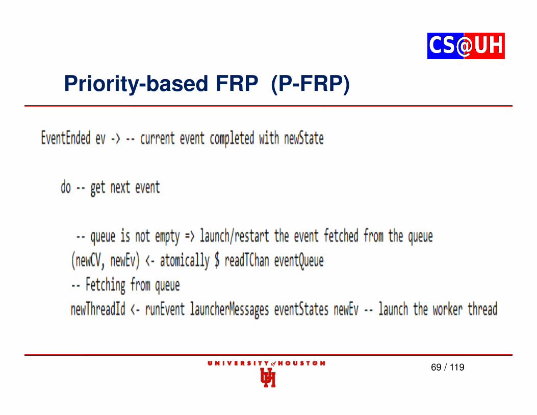
Priority-based FRP (P-FRP)
69 / 119
Priority-based FRP (P-FRP)
Limited Work on Scheduling and Schedulability Analysis
• While there is an extensive understanding of the theory and proof-carrying capability of functional programs and their reactive versions, relatively little work is available on the scheduling of primitives in the corresponding imperative code.
• Also, performance studies of the computational platforms on which these functional programs execute are mostly absent.
70 / 119
Priority-based FRP (P-FRP)
• The worst-case response time of a task is the length of the longest interval from a release of that task till its completion.
• With ANR, interference from higher-priority tasks induces both an interference cost and an abort cost on the response time of the preempted lower-priority task.
• Current focus is on response time analysis with abstract memory and I/O access times. Next challenges include accounting for precise memory and I/O access times.
71 / 119
Priority-based FRP (P-FRP)
• Response time analysis is an exact schedulability test to calculate theworst-case response time of a task which includes the time ofinterference from other higher priority tasks and blocking from lowerpriority tasks.
• RTA is not exact unless blocking is exact - which it is not. If the worst-case response time of a task is longer than its deadline (D), it means thetask will not meet its deadline. The opposite situation is that if the worst-case response time of the task is less than or equal to its deadline, thetask will meet its deadline.
• The analysis can be applied for D = T (task’s period), D < T, or D > T.
72 / 119
Priority-based FRP (P-FRP)
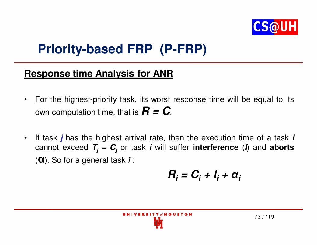
Response time Analysis for ANR
• For the highest-priority task, its worst response time will be equal to its
own computation time, that is R = C.
• If task j has the highest arrival rate, then the execution time of a task i
cannot exceed Tj − Cj or task i will suffer interference (I) and aborts
(α). So for a general task i :
Ri = Ci + Ii + αi
73 / 119
Priority-based FRP (P-FRP)
Interference Cost
• If the execution time of some task i exceeds Tj − Cj, thentask i will never be able to complete execution.
• A simple expression for obtaining this Interference Cost isusing the ceiling function:
74 / 119
Priority-based FRP (P-FRP)
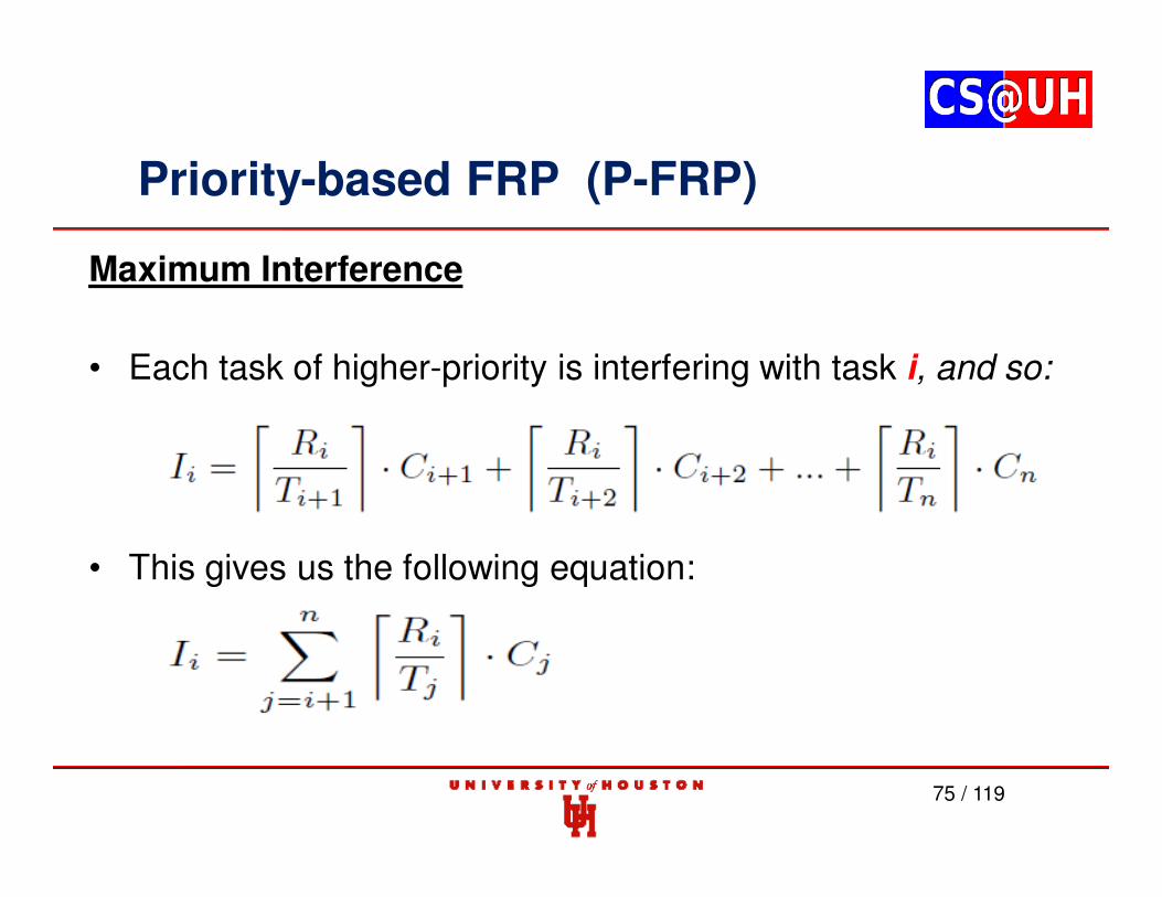
Maximum Interference
• Each task of higher-priority is interfering with task i, and so:
• This gives us the following equation:
75 / 119
Priority-based FRP (P-FRP)
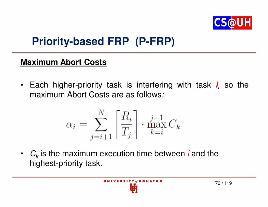
Maximum Abort Costs
• Each higher-priority task is interfering with task i, so themaximum Abort Costs are as follows:
• Ck is the maximum execution time between i and the highest-priority task.
76 / 119
Priority-based FRP (P-FRP)
Maximum Abort Costs
• The maximum abort cost equation is sensible and simple but overly pessimistic. Therefore, the test is said to be sufficientbut not necessary.
77 / 119
Priority-based FRP (P-FRP)
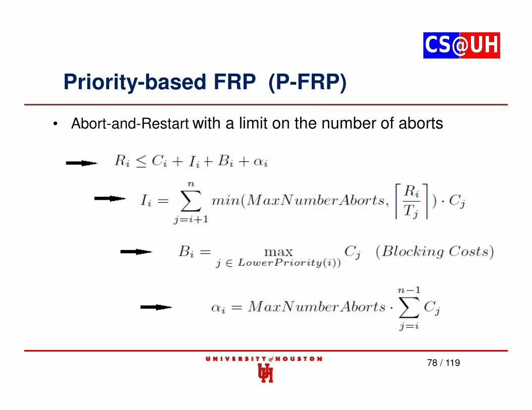
78 / 119
• Abort-and-Restart with a limit on the number of aborts
Priority-based FRP (P-FRP) Example
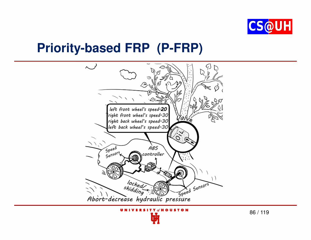
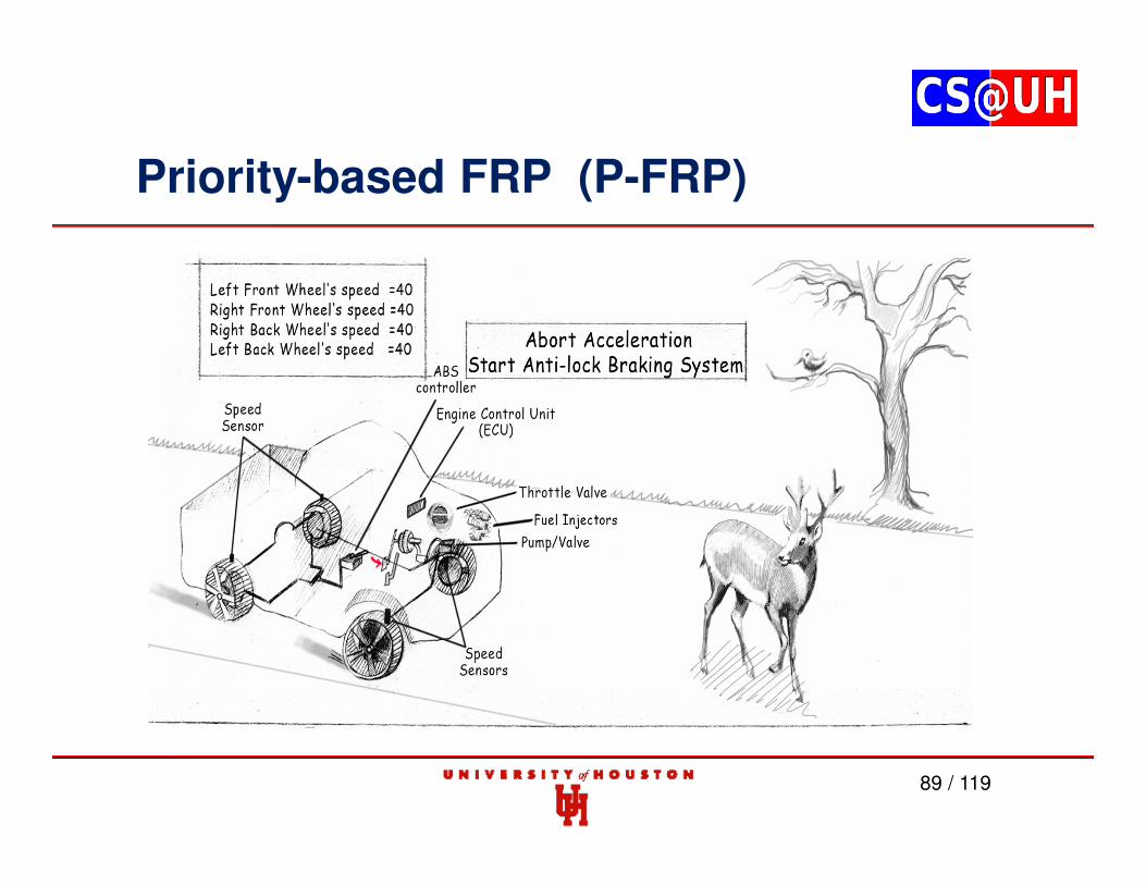
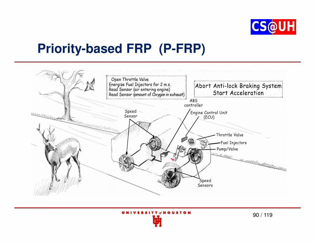
Antilock braking system in a car is a simple example of an embedded hardreal-time system with real-time constraints.
The ABS is expected to release a vehicle’s brakes, preventing dangerouswheel locking, in a predictably short time frame.
ABS uses a kind of an Abort-and-Restart Scheme.
Kaleb R. Christoffersen and Albert M. K. Cheng, ``Model-Based Design: Anti-lock Brake System with Priority-Based Functional Reactive Programming,’’ submitted to RTSS WIP 2013.
79 / 119
Priority-based FRP (P-FRP)
80 / 119
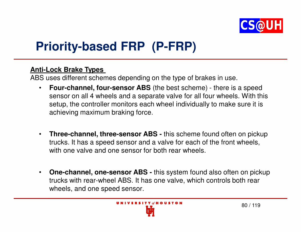
Anti-Lock Brake Types ABS uses different schemes depending on the type of brakes in use.
• Four-channel, four-sensor ABS (the best scheme) - there is a speed sensor on all 4 wheels and a separate valve for all four wheels. With this setup, the controller monitors each wheel individually to make sure it is achieving maximum braking force.
• Three-channel, three-sensor ABS - this scheme found often on pickup trucks. It has a speed sensor and a valve for each of the front wheels, with one valve and one sensor for both rear wheels.
• One-channel, one-sensor ABS - this system found also often on pickup trucks with rear-wheel ABS. It has one valve, which controls both rear wheels, and one speed sensor.
Priority-based FRP (P-FRP)
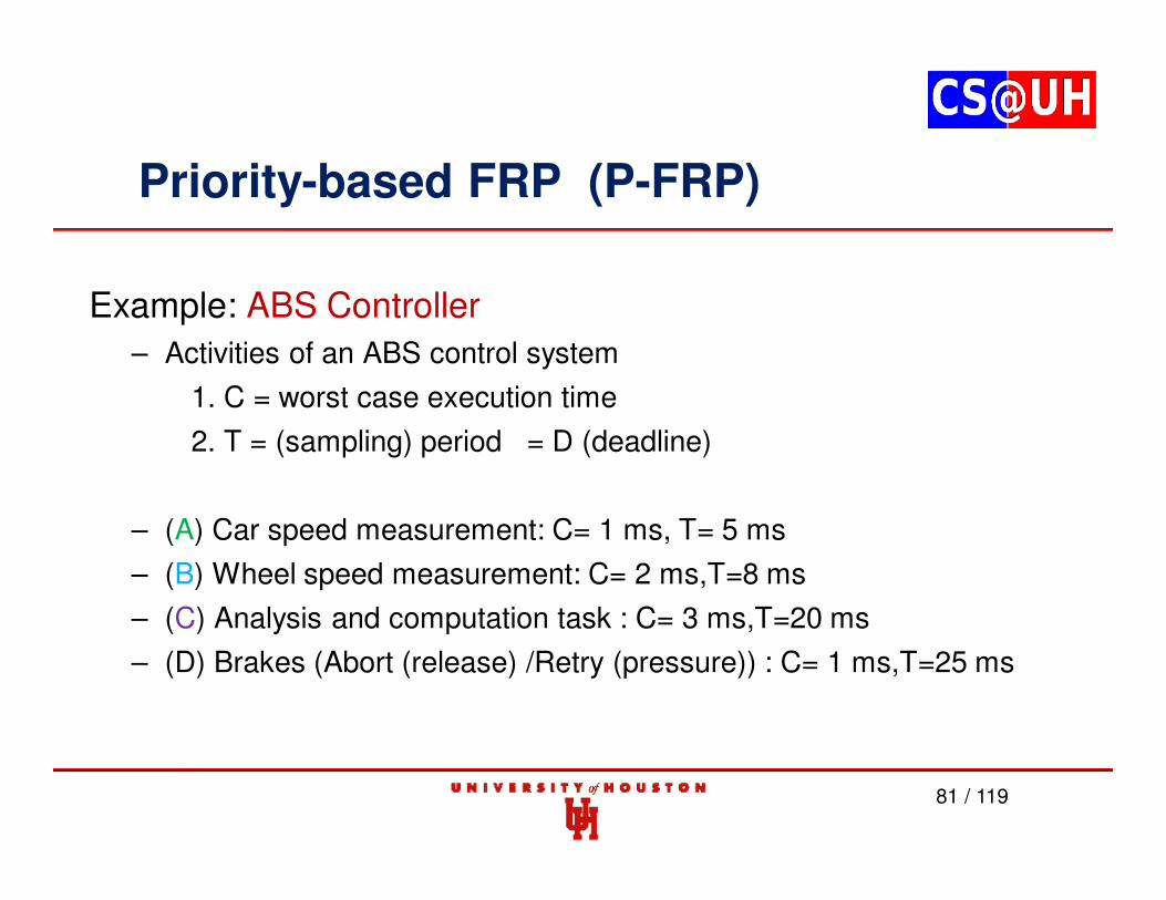
Example: ABS Controller
– Activities of an ABS control system
1. C = worst case execution time
2. T = (sampling) period = D (deadline)
– (A) Car speed measurement: C= 1 ms, T= 5 ms
– (B) Wheel speed measurement: C= 2 ms,T=8 ms
– (C) Analysis and computation task : C= 3 ms,T=20 ms
• At least two hydraulic valves within the brake hydraulics
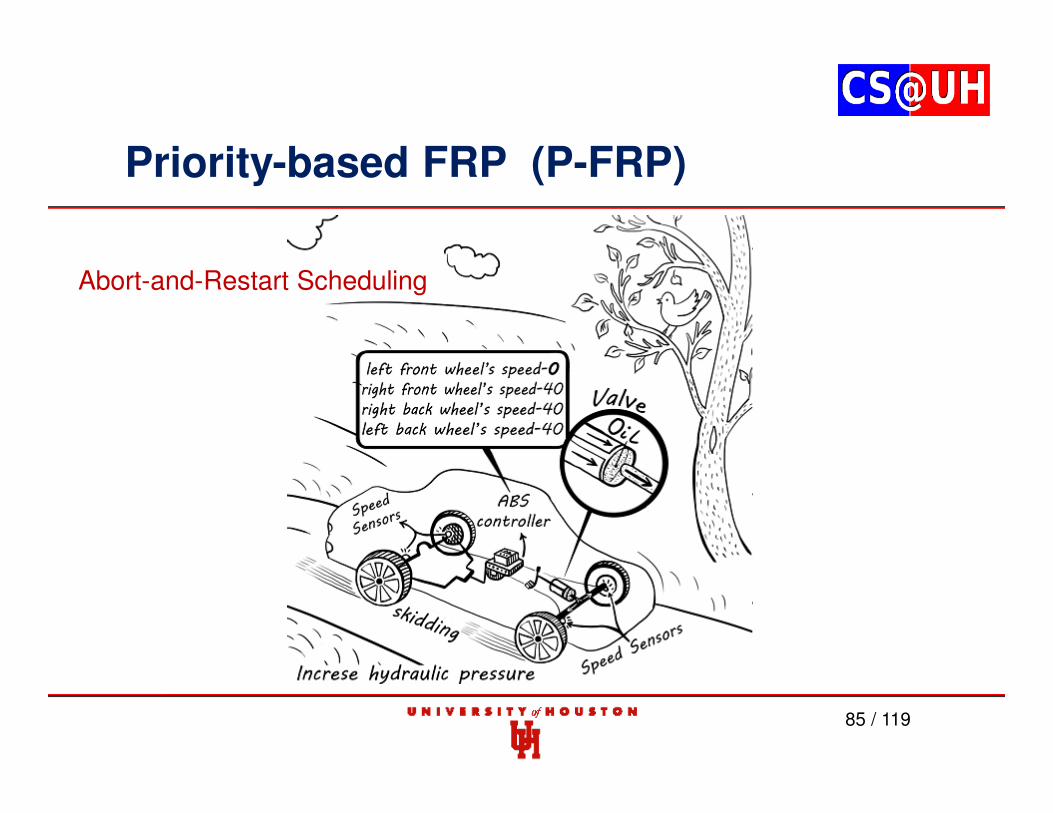
• The ECU constantly monitors the rotational speed of each wheel;if it detects a wheel rotating significantly slower than the others, acondition indicative of impending wheel lock, it actuates the valvesto reduce hydraulic pressure to the brake at the affected wheel,thus reducing the braking force on that wheel; the wheel thenturns faster.
Priority-based FRP (P-FRP)
85 / 119
Abort-and-Restart Scheduling
Priority-based FRP (P-FRP)
86 / 119
Priority-based FRP (P-FRP)
87 / 119
Priority-based FRP (P-FRP)
88 / 119
Priority-based FRP (P-FRP)
89 / 119
Priority-based FRP (P-FRP)
90 / 119
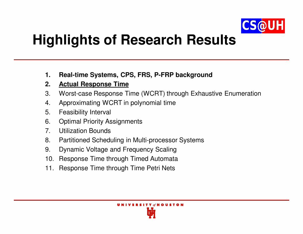
Highlights of Research Results
1. Real-time Systems, CPS, FRS, P-FRP background
2. Actual Response Time
3. Worst-case Response Time (WCRT) through Exhaustive Enumeration
4. Approximating WCRT in polynomial time
5. Feasibility Interval
6. Optimal Priority Assignments
7. Utilization Bounds
8. Partitioned Scheduling in Multi-processor Systems
9. Dynamic Voltage and Frequency Scaling
10. Response Time through Timed Automata
11. Response Time through Time Petri Nets
Priority-based FRP (P-FRP)
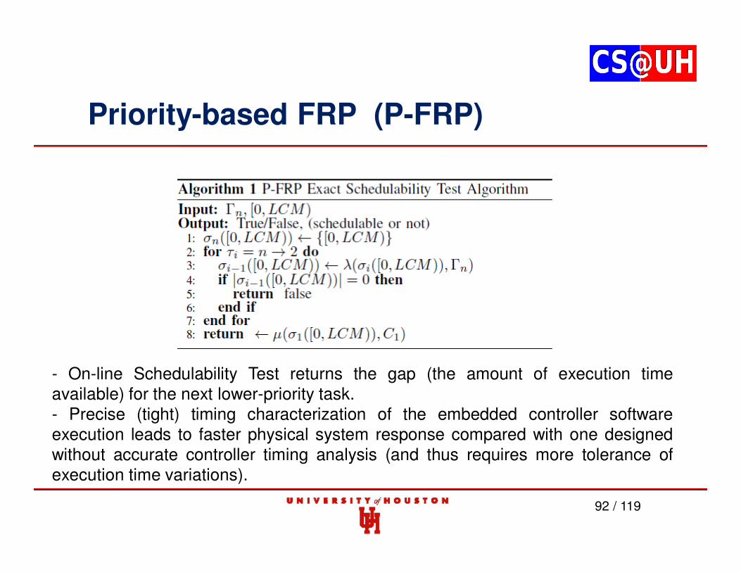
92 / 119
- On-line Schedulability Test returns the gap (the amount of execution timeavailable) for the next lower-priority task.- Precise (tight) timing characterization of the embedded controller softwareexecution leads to faster physical system response compared with one designedwithout accurate controller timing analysis (and thus requires more tolerance ofexecution time variations).
Non-Preemptive Execution
Preemptive Execution
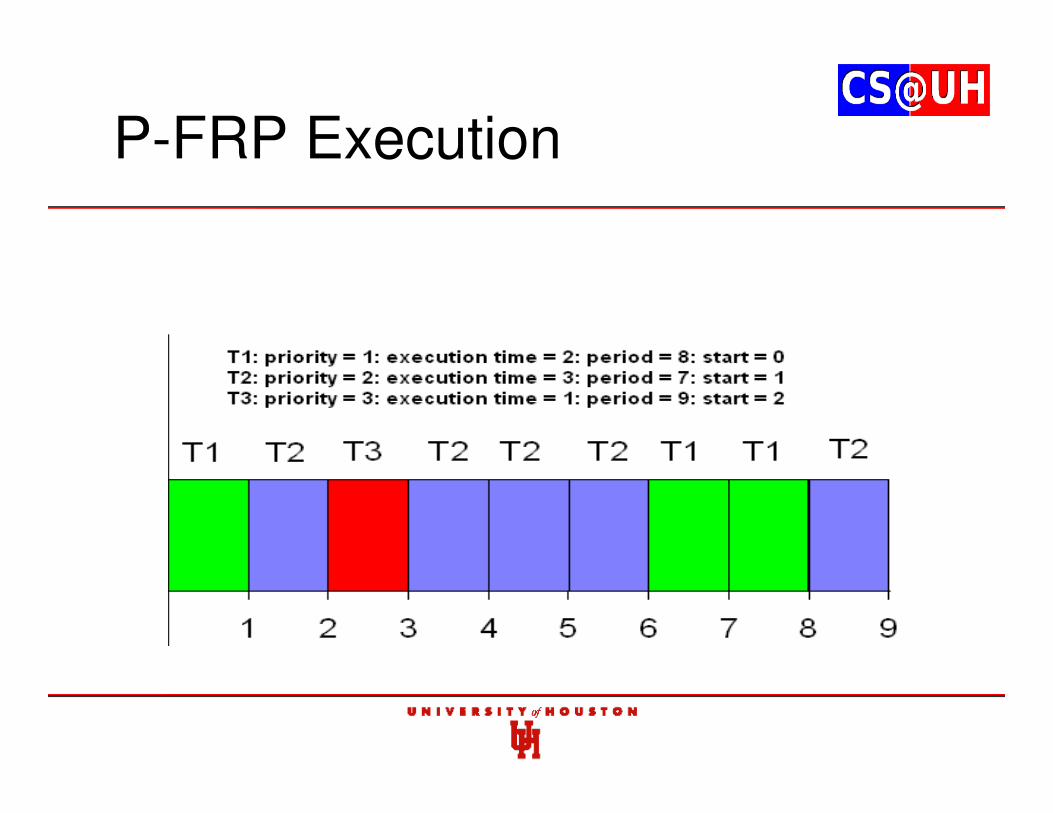
P-FRP Execution
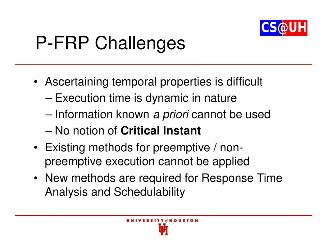
P-FRP Challenges
• Ascertaining temporal properties is difficult
– Execution time is dynamic in nature
– Information known a priori cannot be used
– No notion of Critical Instant
• Existing methods for preemptive / non-preemptive execution cannot be applied
• New methods are required for Response Time Analysis and Schedulability
Critical Instant -Synchronous
Critical Instant -Asynchronous
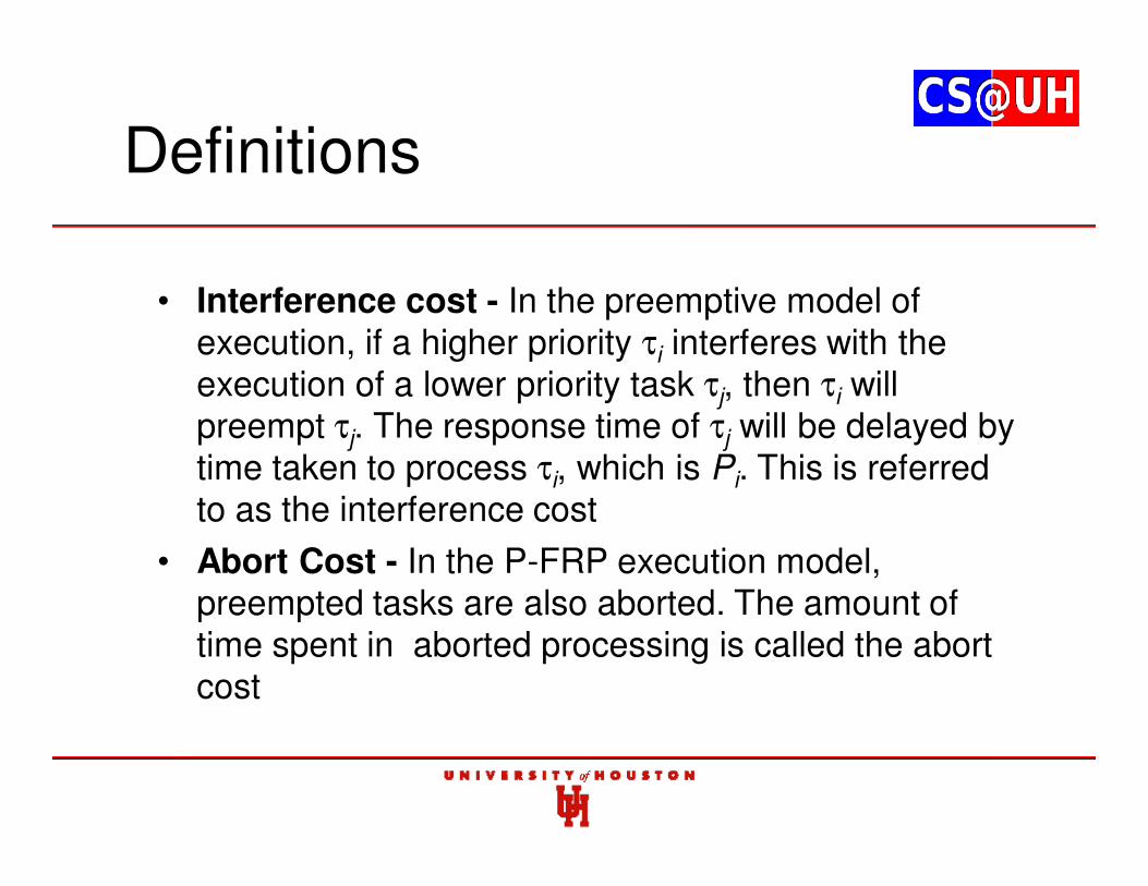
Definitions
• Interference cost - In the preemptive model of execution, if a higher priority τi interferes with the execution of a lower priority task τj, then τi will preempt τj. The response time of τj will be delayed by time taken to process τi, which is Pi. This is referred to as the interference cost
• Abort Cost - In the P-FRP execution model, preempted tasks are also aborted. The amount of time spent in aborted processing is called the abort cost
Contributions
• This work deals with finding actual response time in P-FRP
• Actual response time is not an approximate value
• Actual response time is found for a priori known release scenario
• Method for finding actual response time is required for determining worst-case response time …
… as well as developing exact schedulability tests, analyzing multi-processor schedulability etc.
Existing Approach: Audsley et al
Existing Approach: Audsley et al
527
21
4
22 =⋅
+⋅
+
627
51
4
52 =⋅
+⋅
+
627
61
4
62 =⋅
+⋅
+
Iteration 1 : 227
01
4
02 =⋅
+⋅
+
Iteration 2 :
Iteration 3 :
Iteration 4 :
Existing Approach: Ras & Cheng
• Extension of Audsley’s Method
• Abort cost is added on response time
• Abort cost from each higher priority task is accounted for
• Computed response time is not exact, but an upper bound on WCRT
• Solution does not converge for several cases
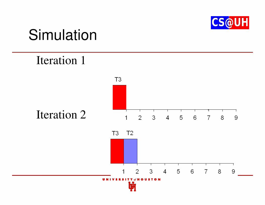
Simulation
• Iteration 1•
Iteration 2
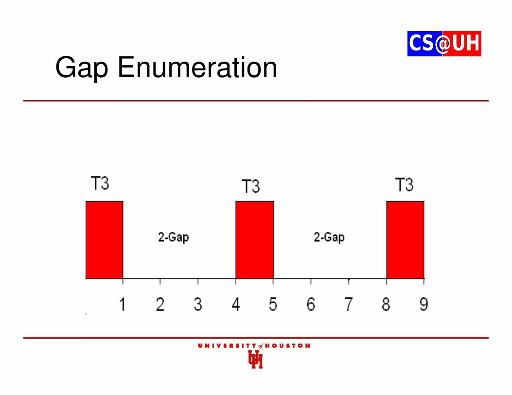
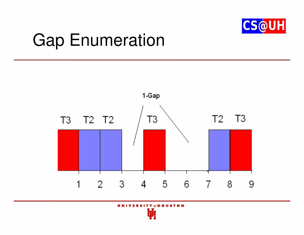
Gap Enumeration
Gap Enumeration
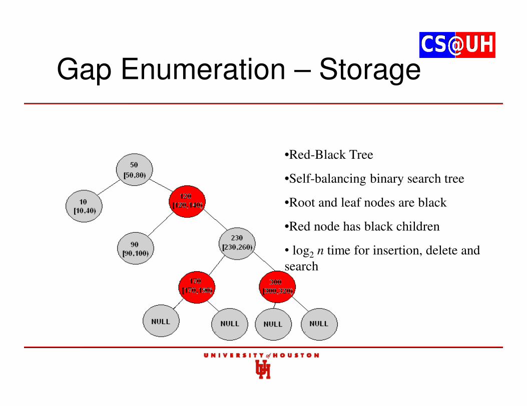
Gap Enumeration – Storage
•Red-Black Tree
•Self-balancing binary search tree
•Root and leaf nodes are black
•Red node has black children
• log2 n time for insertion, delete and
search
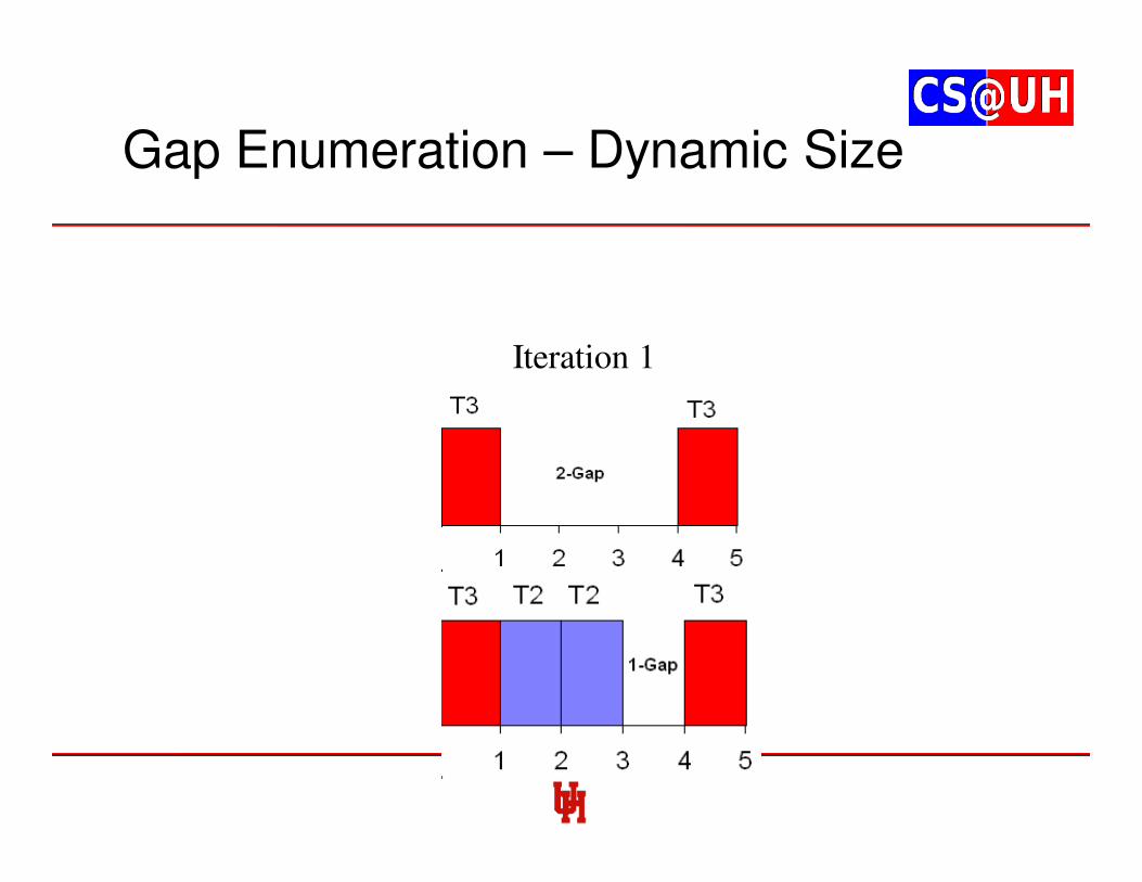
Gap Enumeration – Dynamic Size
Iteration 1
Gap Enumeration – Dynamic Size
Iteration 1
Experimental Analysis
7 Tasks
0
2000
4000
6000
8000
10000
0 100 200 300 400 500
Task Set Number
Com
puta
tion S
teps
# Steps-TAS # Steps-GE
Remarks
• New method for response time computation
• Can compute response time under any given release scenario
• Chaitanya Belwal and Albert M. K. Cheng, “Determining Actual Response Time in P-FRP”, 13th International Symposium on Practical Aspects of Declarative Languages (PADL), Austin, Texas, USA January 24-25, 2011
Contents
1. P-FRP and Real-time Systems background
2. Actual Response Time
3. Worst-case Response Time (WCRT) through Exhaustive Enumeration
4. Approximating WCRT in polynomial time
5. Feasibility Interval
6. Optimal Priority Assignments
7. Utilization Bounds
8. Partitioned Scheduling in Multi-processor Systems
9. Dynamic Voltage and Frequency Scaling
10. Response Time through Timed Automata
11. Response Time through Time Petri Nets
Determining Exact WCRT
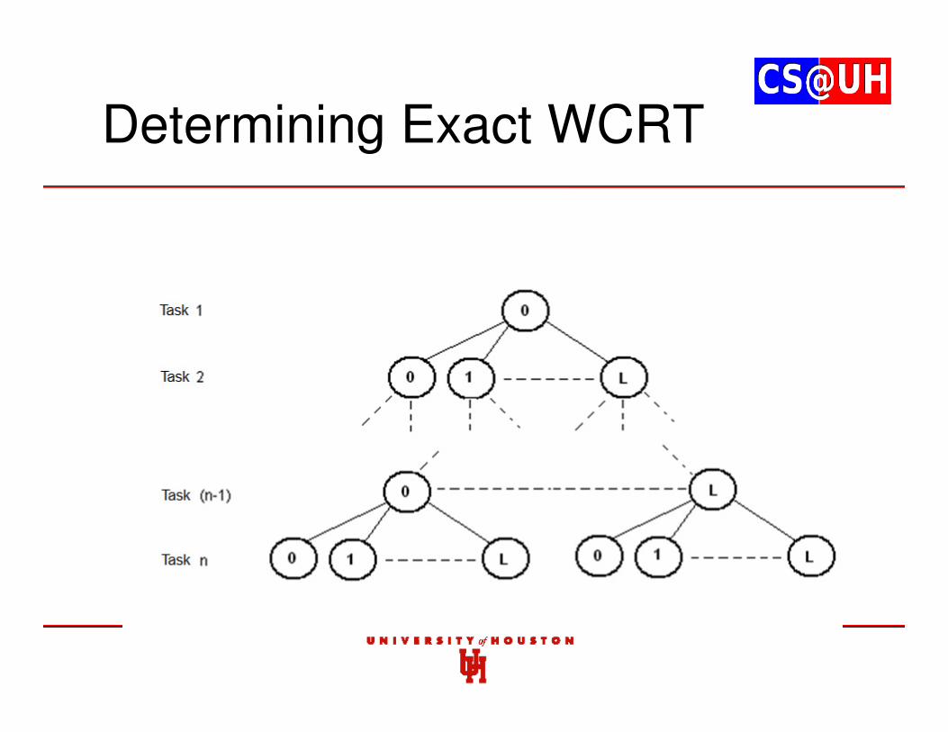
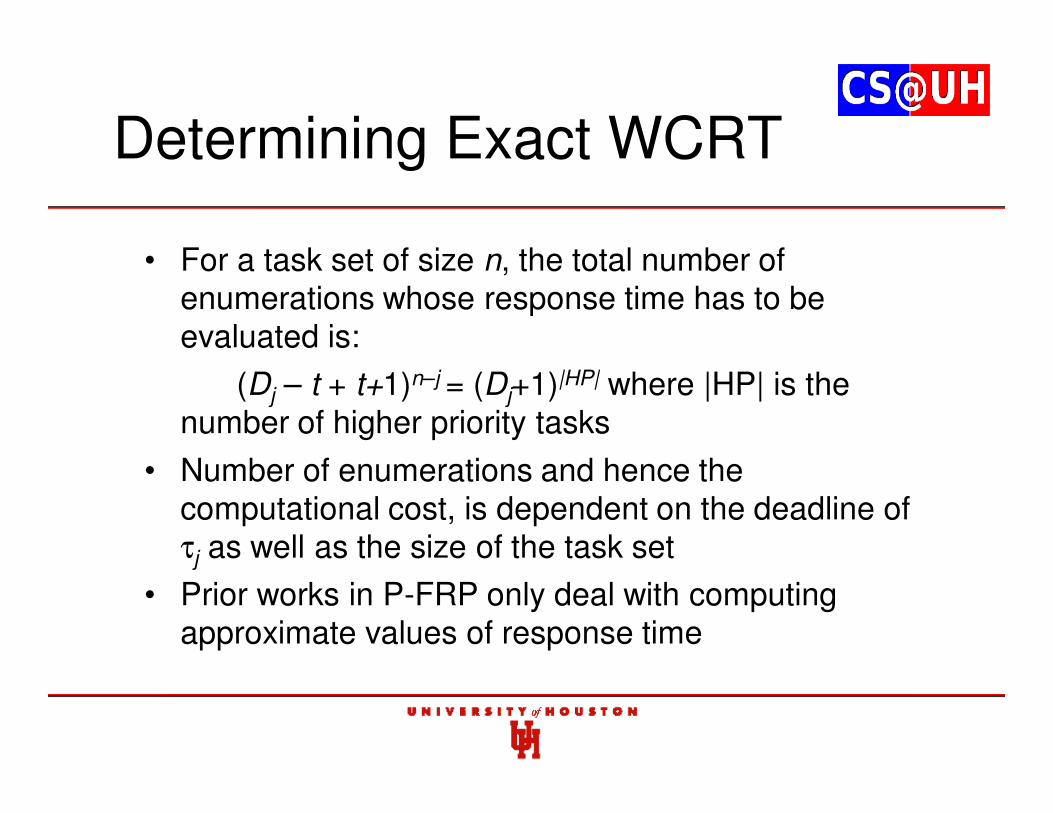
Determining Exact WCRT
• For a task set of size n, the total number of enumerations whose response time has to be evaluated is:
(Dj – t + t+1)n–j = (Dj+1)|HP| where |HP| is the number of higher priority tasks
• Number of enumerations and hence the computational cost, is dependent on the deadline of τj as well as the size of the task set
• Prior works in P-FRP only deal with computing approximate values of response time
Contributions
• We present techniques for determining the lower and upper bound on release offset of higher priority tasks for computation of exact WCRT in P-FRP
• This reduces the number of enumerated release scenarios by a considerable amount
• Highlight schedulability characteristics
• Present algorithm to computer release offset upper bound
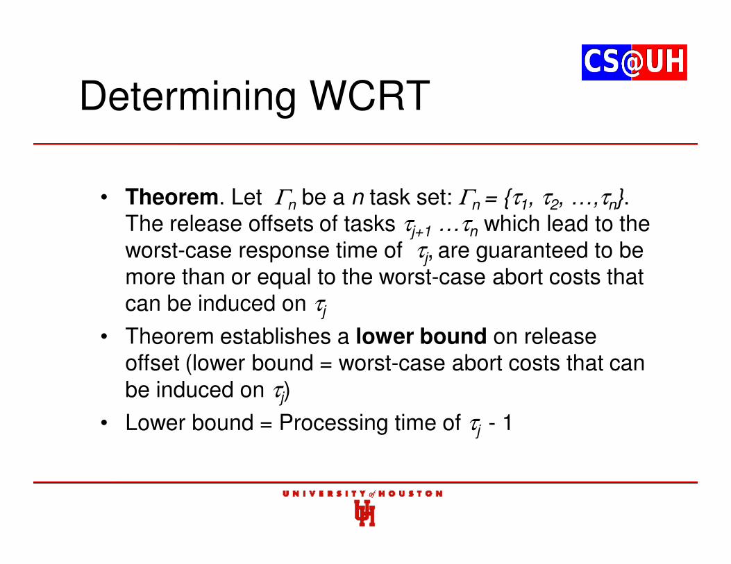
Determining WCRT
• Theorem. Let Γn be a n task set: Γn = {τ1, τ2, …,τn}. The release offsets of tasks τj+1 …τn which lead to the worst-case response time of τj, are guaranteed to be more than or equal to the worst-case abort costs that can be induced on τj
• Theorem establishes a lower bound on release offset (lower bound = worst-case abort costs that can be induced on τj)
• Lower bound = Processing time of τj - 1
Determining WCRT
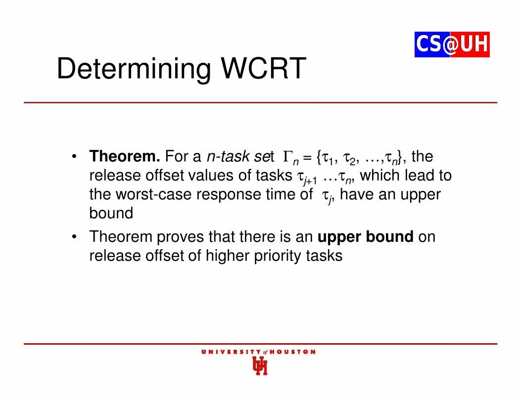
• Theorem. For a n-task set Γn = {τ1, τ2, …,τn}, the release offset values of tasks τj+1 …τn, which lead to the worst-case response time of τj, have an upper bound
• Theorem proves that there is an upper bound on release offset of higher priority tasks
Release Offset Upper Bound
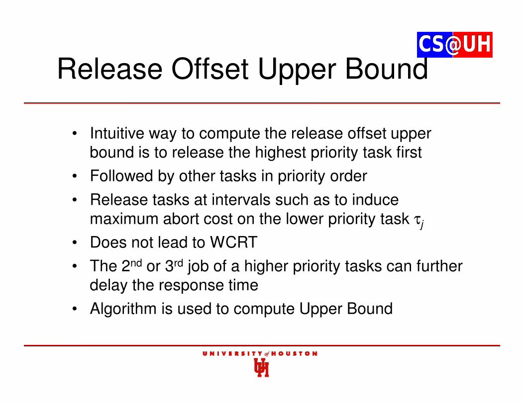
• Intuitive way to compute the release offset upper bound is to release the highest priority task first
• Followed by other tasks in priority order
• Release tasks at intervals such as to induce maximum abort cost on the lower priority task τj
• Does not lead to WCRT
• The 2nd or 3rd job of a higher priority tasks can further delay the response time
• Algorithm is used to compute Upper Bound
Results – 5 Tasks
0
5
10
15
20
25
30
0 100 200 300 400 500
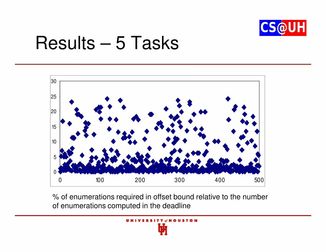
% of enumerations required in offset bound relative to the number of enumerations computed in the deadline
Remarks
• Till now all release offset scenarios in the period [0,Tj) have to be evaluated to determine WCRT of τj
• Our approach requires evaluation between the release offset bounds and is more efficient
• Chaitanya Belwal, Albert M. K. Cheng and Walid Taha, “Release Offset Bounds for Response Time Analysis of P-FRP”, 8th IEEE International Conference on Embedded Software and Systems (ICESS), Changsha, China, Nov. 16-18, 2011
Contents
1. P-FRP and Real-time Systems background
2. Actual Response Time
3. Worst-case Response Time (WCRT) through Exhaustive Enumeration
4. Approximating WCRT in polynomial time
5. Feasibility Interval
6. Optimal Priority Assignments
7. Utilization Bounds
8. Partitioned Scheduling in Multi-processor Systems
9. Dynamic Voltage and Frequency Scaling
10. Response Time through Timed Automata
11. Response Time through Time Petri Nets
Approximate WCRT in Polynomial Time
• As shown, Audsley’s method cannot be used to determine response time in P-FRP
• Ras and Cheng’s method computes approximate value of WCRT…
• …However this method does not converge for several task sets
• Guaranteed method for approximating WCRT in P-FRP is required
Contributions
• Derive an algorithm to compute approximate values of WCRT in P-FRP
• This algorithm is guaranteed to converge to a result
• Approximation factors evaluated through experimental task sets
Algorithm Outline
• Set lower bound of WCRT equal to the value computed by Audsley’s algorithm
• Use the lower bound as a base value and add interference and abort costs
• Run an iterative loop based on number of higher priority tasks
• Add costs for prior tasks in every iteration
• Iterative loop is guaranteed to complete
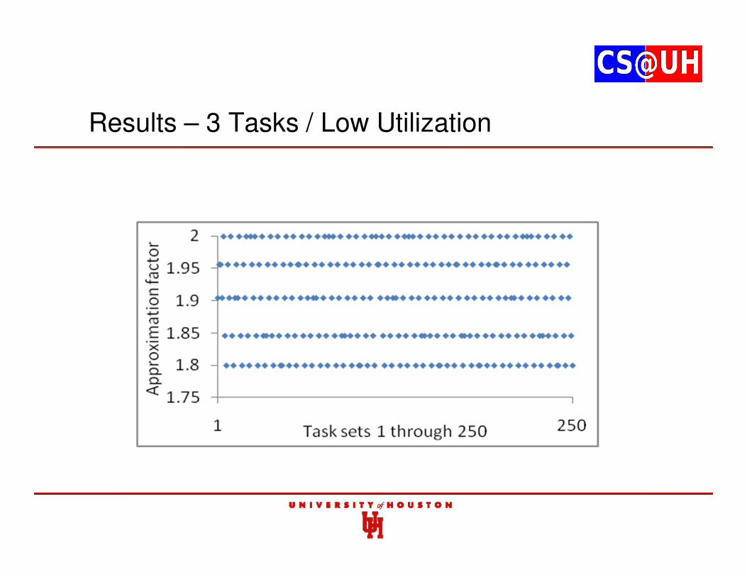
Results – 3 Tasks / Low Utilization
Results – 5 Tasks / Low Utilization
Results – 3 Tasks / High Utilization
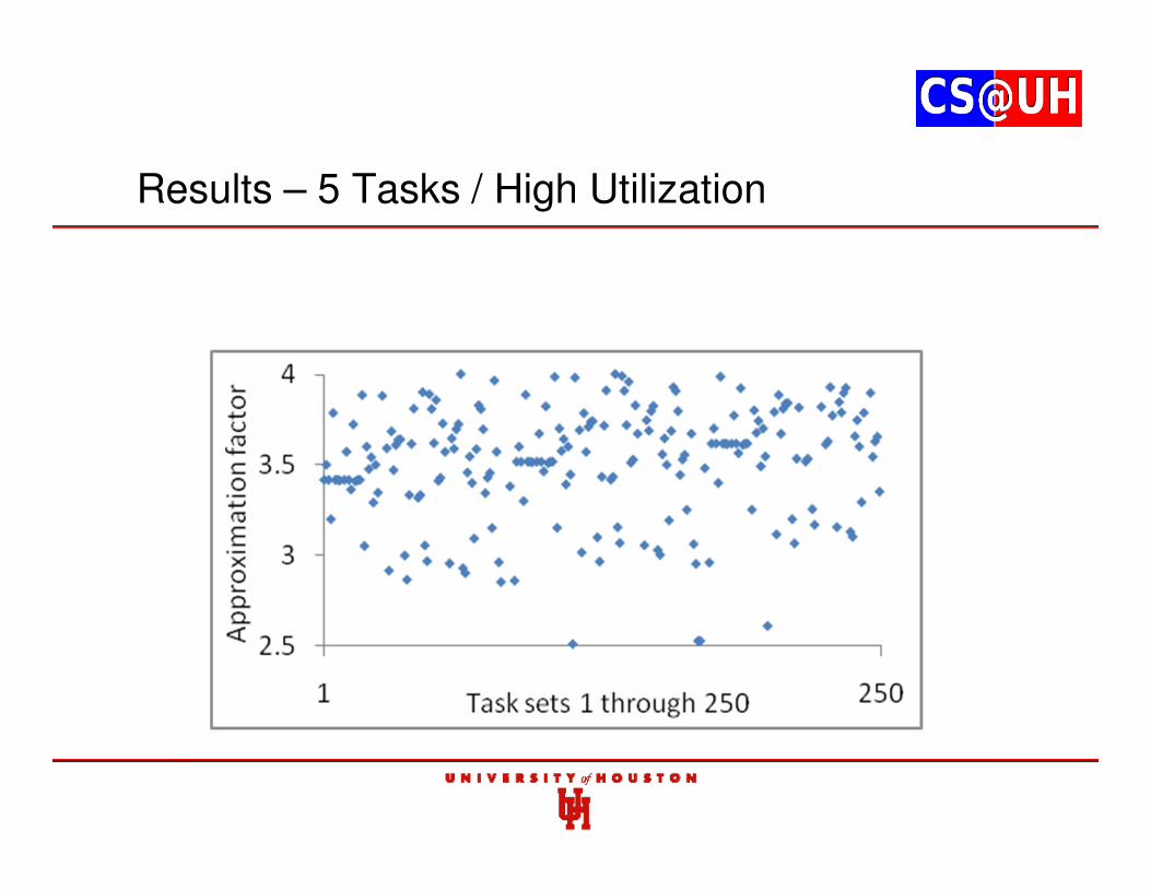
Results – 5 Tasks / High Utilization
Remarks
• High approximation factor for larger task sets due to larger pessimism in abort costs
• Reducing pessimism while maintaining correctness is challenging
• C. Belwal, A. M. K. Cheng, W. Taha, and A. Zhu, “Time Analysis of the Priority based FRP System”, IEEE-CS Real-Time and Embedded Technology and Applications Symposium WIP Session, St. Louis, MO, April 22-24, 2008
Contents
1. P-FRP and Real-time Systems background
2. Actual Response Time
3. Worst-case Response Time (WCRT) through Exhaustive Enumeration
4. Approximating WCRT in polynomial time
5. Feasibility Interval
6. Optimal Priority Assignments
7. Utilization Bounds
8. Partitioned Scheduling in Multi-processor Systems
9. Dynamic Voltage and Frequency Scaling
10. Response Time through Timed Automata
11. Response Time through Time Petri Nets
Feasibility Interval
• Real-time System tasks can run infinitely often
• No tasks should have a deadline miss as long as system is running (hard real-time)
• Ascertaining schedulability for an infinite period is not possible
• Finite time is used to analyze schedulability
• Termed feasibility interval in real-time studies
Feasibility Interval for Preemptive Execution
• In their seminal paper, Liu and Layland have shown that the WCRT occurs when tasks are released synchronously (at the same time)
• The feasibility interval in a synchronous release is [0, L), where L is the least common multiple of all task periods
• Schedulability in [0,L) guarantees schedulability since worst-case schedulability is also analyzed
Contributions
• Formally present execution characteristics of tasks in a P-FRP system with 2 tasks
• Formally present execution characteristics of tasks in a P-FRP system with > 2 tasks
• Derive the feasibility interval of P-FRP
Processing Pattern
• Two time intervals of equal lengths [t1, t1+a) and [t2, t2+a) are said to have the same processing pattern, if for every value of relative time t: 0 ≤ t < a, the task that is processed at relative time t in [t1, t1+a) (absolute time t1 + t), is also processed at relative time t in [t2, t2+a) (absolute time t2 + t)
Feasibility Interval in P-FRP
• In P-FRP preempted tasks are aborted
• Leads to different execution semantics
• Unknown if feasibility interval of the preemptive model can be applied to this execution model
• Fresh approach required to determine the feasibility interval
Feasibility Interval
• Theorem. For Γn={τ1, τ2,…, τn} and Rmax =
max{Φi}, the feasibility interval of Γn is [t,
t+L), where t ≥ Rmax
• Corollary. The earliest feasibility interval of Γn is [Rmax, Rmax+L)
• Corollary. If all tasks in Γn are synchronously released, then the earliest feasibility interval is [0, L)
Remarks
• Formally derived the feasibility interval in P-FRP
• Can be extended to consider non-periodic tasks
• Chaitanya Belwal and Albert M. K. Cheng, “Feasibility Interval for the Transactional Event Handlers of P-FRP”, 8th IEEE International Conference on Embedded Software and Systems (ICESS), Changsha, China, Nov.
16-18, 2011.
Contents
1. P-FRP and Real-time Systems background
2. Actual Response Time
3. Worst-case Response Time (WCRT) through Exhaustive Enumeration
4. Approximating WCRT in polynomial time
5. Feasibility Interval
6. Optimal Priority Assignments
7. Utilization Bounds
8. Partitioned Scheduling in Multi-processor Systems
9. Dynamic Voltage and Frequency Scaling
10. Response Time through Timed Automata
11. Response Time through Time Petri Nets
Optimal Priority Assignments
• Rate-Monotonic (RM) priority assignment is optimal in the preemptive model (Liu and Layland)
• RM is not optimal in P-FRP ...
• … can be easily proven with an example
• Unknown if an optimal priority assignment can even exist for this execution model
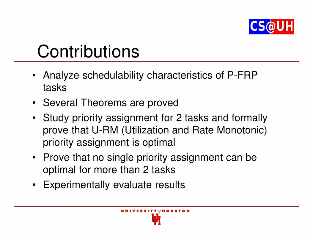
Contributions• Analyze schedulability characteristics of P-FRP
tasks
• Several Theorems are proved
• Study priority assignment for 2 tasks and formally prove that U-RM (Utilization and Rate Monotonic) priority assignment is optimal
• Prove that no single priority assignment can be optimal for more than 2 tasks
• Experimentally evaluate results
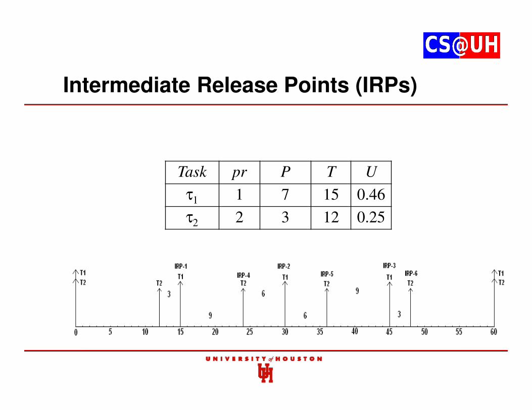
Intermediate Release Points (IRPs)
Task pr P T U
τ1 1 7 15 0.46
τ2 2 3 12 0.25
Results
Remarks
• U-RM is the optimal priority assignment in 2-task sets
• For more than 2 tasks no single priority assignment can be optimal
• Several large tasks sets are still U-RM schedulable
• Chaitanya Belwal and Albert M. K. Cheng. “On Priority Assignment in P-FRP”, Proc. IEEE-CS Real-Time and Embedded Technology and Applications Symposium (RTAS) WIP Session, Stockholm, Sweden, April 13-16, 2010
Contents
1. P-FRP and Real-time Systems background
2. Actual Response Time
3. Worst-case Response Time (WCRT) through Exhaustive Enumeration
4. Approximating WCRT in polynomial time
5. Feasibility Interval
6. Optimal Priority Assignments
7. Utilization Bounds
8. Partitioned Scheduling in Multi-processor Systems
9. Dynamic Voltage and Frequency Scaling
10. Response Time through Timed Automata
11. Response Time through Time Petri Nets
12. Analysis Tools
Utilization-based Sufficient Tests
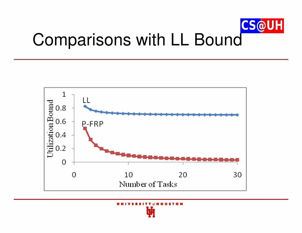
• Liu and Layland’s (LL) utilization bound is widely used as a sufficient schedulability test
U ≤ n·(21/n – 1)
n = number of tasks,
U = sum of utilization ratios of all tasks
• For 2 tasks U ≤ 0.83, for 3 tasks U ≤ 0.78 etc, for task set to be guaranteed schedulable
Utilization-based Sufficient Tests
• Liu and Layland’s bound is derived by considering worst-case release scenario
• Worst-case release scenario is also assumed in derivations of other schedulability tests (e.g. Bini and Baruah’s)
• Worst-case scenario is derived using critical instant
• In P-FRP, the worst case release scenario is not the synchronous release of tasks
Contributions
• Derive a worst-case release scenario with 2 P-FRP tasks
• Use this worst-case scenario to derive sufficient utilization bounds for P-FRP tasks sets with 2 tasks
• Prove that worst-case scenario for 2 and n (n > 2) tasks is different
• Present a pessimistic condition with n tasks
• Use the pessimistic condition to derive utilization bound for n tasks
• Experimental Analysis
Utilization Bound for 2 Tasks
• Theorem. A task set with 2 tasks {τ1, τ2} where T2 ≤ 2·T1 is guaranteed to be schedulable when the total utilization factor U of this task set is less than or equal to 0.5. Or, the sufficient utilization bound of the task when T2 ≤ 2·T1 is: U ≤ 0.5.
• When T2 > 2·T1 then tasks with U → 0 can also be schedulable, and a sufficient bound does not exist
Utilization Bound with nTasks
• Approach used for 2 tasks cannot be directly applied
• Worst-case release scenario can be different for unique task sets
• Identify a low utilization task set
• Derive bound under full utilization for this task set
Utilization Bound for n Tasks
Worst-case release scenario for a pessimistic task set
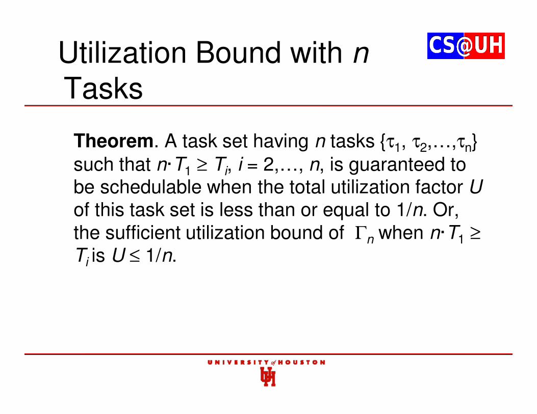
Utilization Bound with nTasks
Theorem. A task set having n tasks {τ1, τ2,…,τn} such that n·T1 ≥ Ti, i = 2,…, n, is guaranteed to be schedulable when the total utilization factor Uof this task set is less than or equal to 1/n. Or, the sufficient utilization bound of Γn when n·T1 ≥
Ti is U ≤ 1/n.
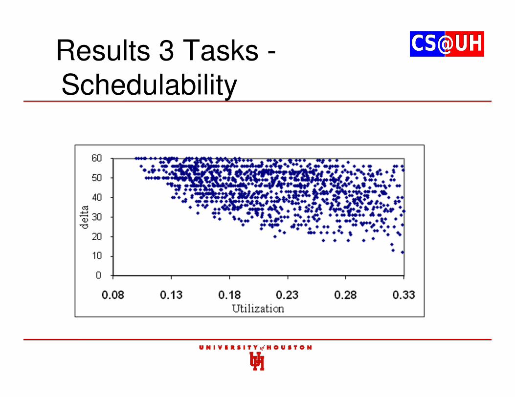
Results 3 Tasks -Schedulability
Results 3 Tasks -Unschedulability
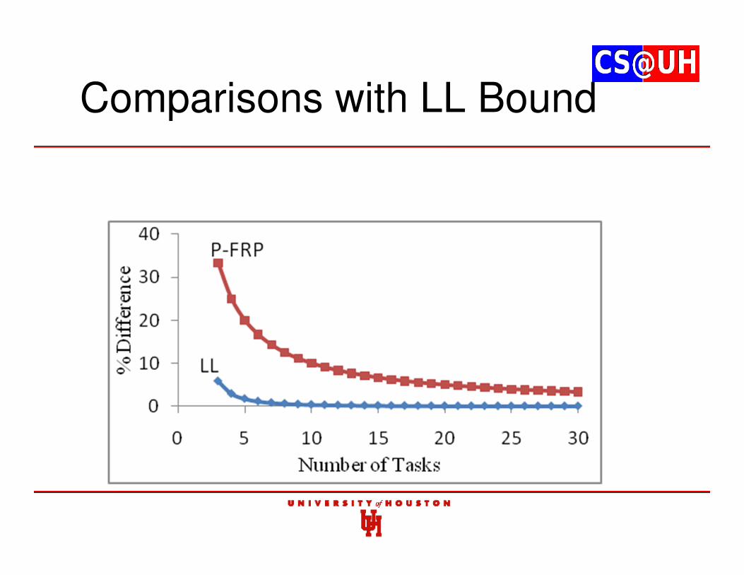
Comparisons with LL Bound
Comparisons with LL Bound
Remarks
• Determined sufficient utilization condition for P-FRP task sets
• Chaitanya Belwal and Albert M. K. Cheng, “A Utilization based Sufficient Condition for P-FRP”, IEEE/IFIP International Conference on Embedded and Ubiquitous Computing (EUC), Melbourne, Australia, Oct 24-26, 2011
Contents
1. P-FRP and Real-time Systems background
2. Actual Response Time
3. Worst-case Response Time (WCRT) through Exhaustive Enumeration
4. Approximating WCRT in polynomial time
5. Feasibility Interval
6. Optimal Priority Assignments
7. Utilization Bounds
8. Partitioned Scheduling in Multi-processor Systems
9. Dynamic Voltage and Frequency Scaling
10. Response Time through Timed Automata
11. Response Time through Time Petri Nets
Static vs. Global Partitioning
• Partitioning refers to assignment of tasks that will execute in a processor
• In static partitioning, task assignment to processors is done offline
• Task assignment cannot be changed while system is running
• Global partitioning is dynamic, and tasks can move between processors while system is running
• No partitioning scheme is ideal
Contributions
• Study static partitioning of P-FRP in multi-processor systems
• Develop an exact schedulability test for P-FRP tasks
• Three schemes applying first-fit algorithm on different sorting criterion
• Partitioning schemes analyzed in rigorous experimental analysis by comparing it with an optimal scheme
• Valid for synchronous release of tasks
Exact Schedulability Test
Exact Schedulability Test
Bin-Packing
• Classical NP-hard problem in Computer Science
• Object with different sizes are packed in finite number of bins
• Has previously been used in static partitioning of tasks in SMP platforms
• Tasks are sorted using some criterion
• First-fit, last-fit heuristics widely used
Bin-Packing with Schedulability Test
• Tasks are sorted based on a defined criterion
• First-fit scheme is used
• P-FRP exact schedulability test is used to identify if processor (bin) is ‘full’
• Tasks are assigned to the next processor until it is ‘full’ and so on
• After last task in sorted order is assigned to a processor, partitioning is complete
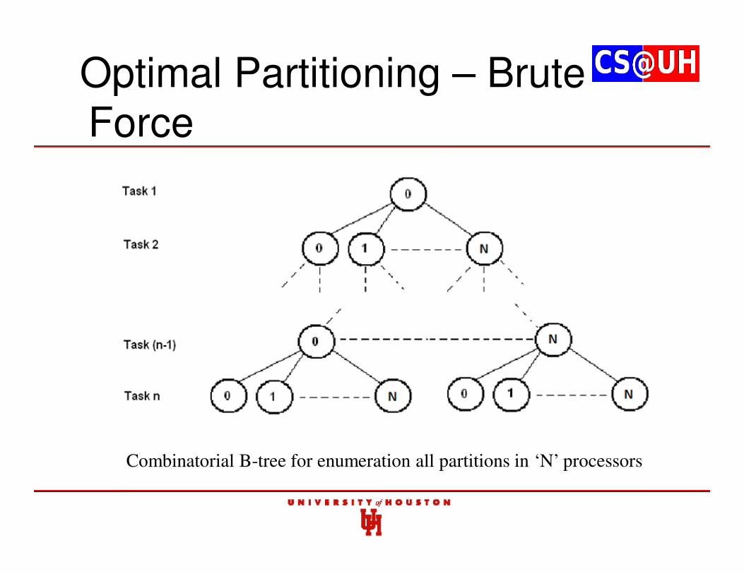
Optimal Partitioning – Brute Force
Combinatorial B-tree for enumeration all partitions in ‘N’ processors
Difference with Optimal: FFDR
0
1
2
3
0 100 200 300 400 500
Task Set
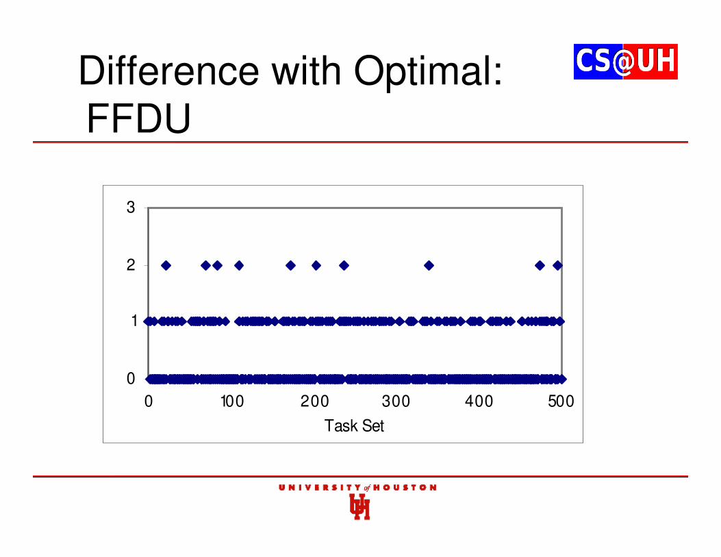
Difference with Optimal: FFDU
0
1
2
3
0 100 200 300 400 500
Task Set
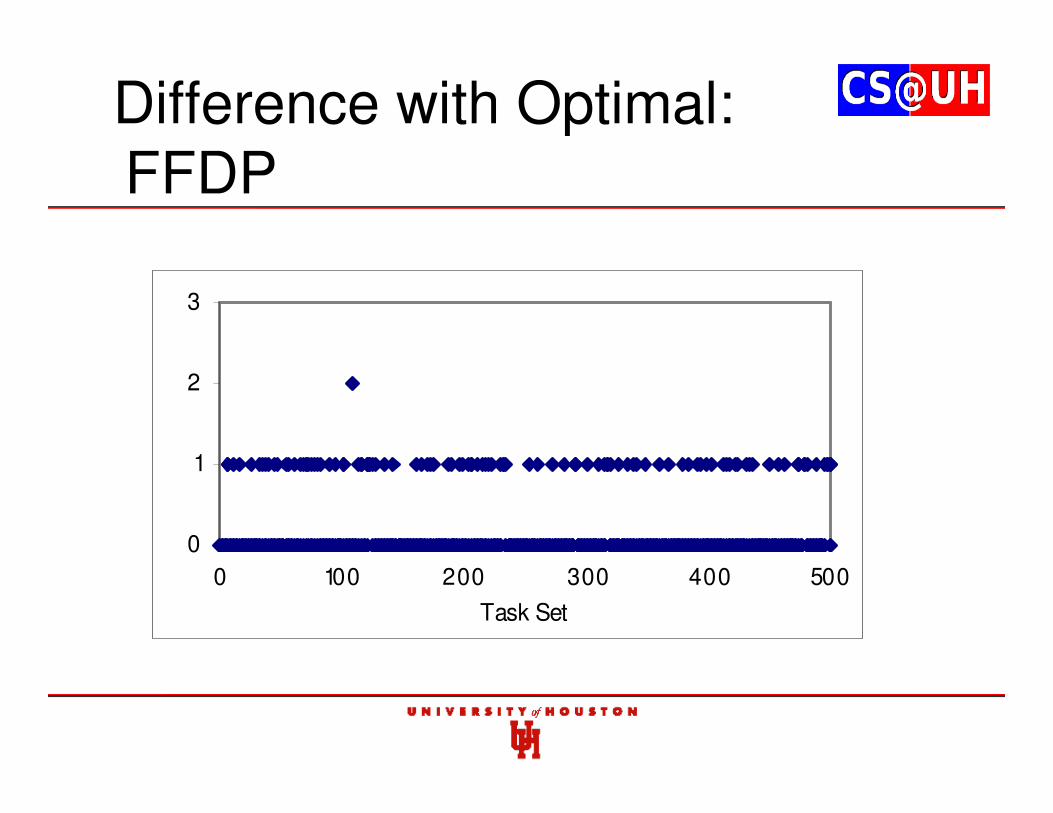
Difference with Optimal: FFDP
0
1
2
3
0 100 200 300 400 500
Task Set
Remarks
• Applied first-fit partitioning using a new exact schedulability test for P-FRP
• Three sorting criterion used with first-fit algorithms
• Chaitanya Belwal and Albert M. K. Cheng, “Partitioned Scheduling of P-FRP in Symmetric Homogeneous Multiprocessors”, IEEE/IFIP International Conference on Embedded and Ubiquitous Computing (EUC), Melbourne, Australia, Oct 24-26, 2011
Contents
1. P-FRP and Real-time Systems background
2. Actual Response Time
3. Worst-case Response Time (WCRT) through Exhaustive Enumeration
4. Approximating WCRT in polynomial time
5. Feasibility Interval
6. Optimal Priority Assignments
7. Utilization Bounds
8. Partitioned Scheduling in Multi-processor Systems
9. Dynamic Voltage and Frequency Scaling
10. Response Time through Timed Automata
11. Response Time through Time Petri Nets
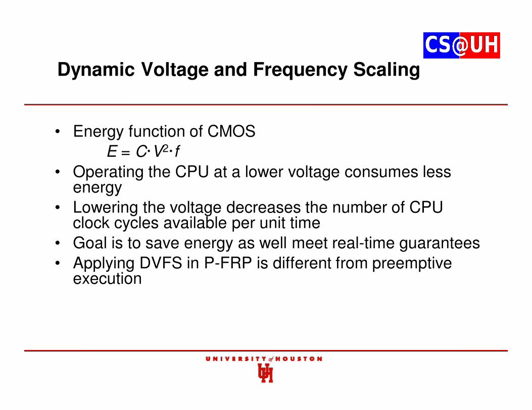
Dynamic Voltage and Frequency Scaling
• Energy function of CMOS
E = C·V2·f
• Operating the CPU at a lower voltage consumes less energy
• Lowering the voltage decreases the number of CPU clock cycles available per unit time
• Goal is to save energy as well meet real-time guarantees
• Applying DVFS in P-FRP is different from preemptive execution
Contributions
• Derived Schedulability conditions for Static DVFS
• Presented algorithm for Progressive Voltage Scale (PVS)
• Presented the Voltage Scaling Points (VSP) algorithm
• Experimental evaluations and comparison between each approach
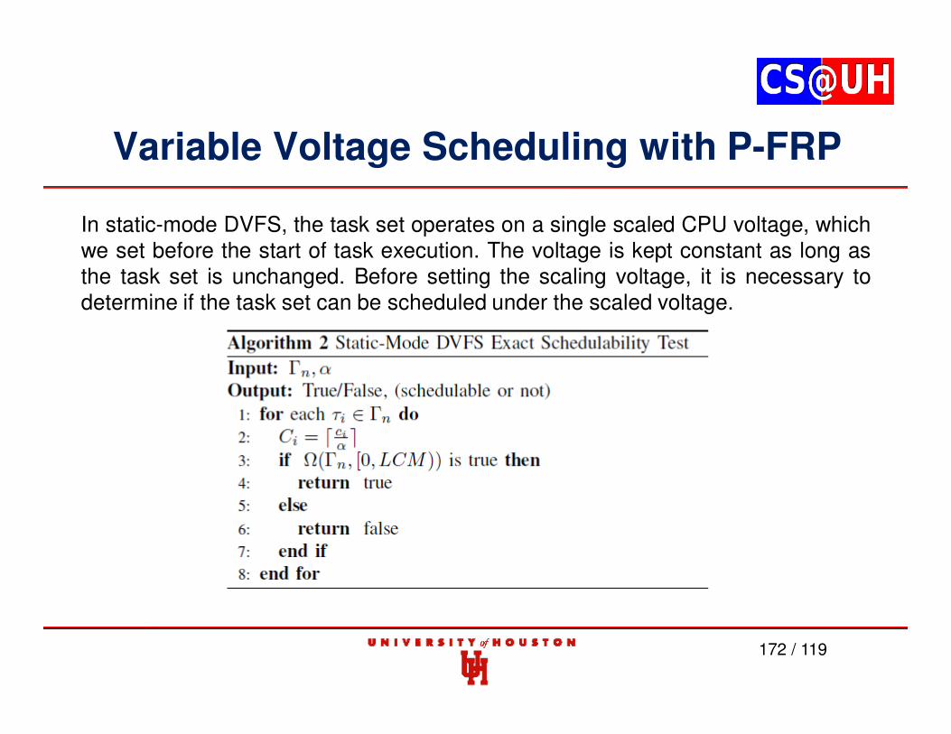
Variable Voltage Scheduling with P-FRP
172 / 119
In static-mode DVFS, the task set operates on a single scaled CPU voltage, whichwe set before the start of task execution. The voltage is kept constant as long asthe task set is unchanged. Before setting the scaling voltage, it is necessary todetermine if the task set can be scheduled under the scaled voltage.
Variable Voltage Scheduling with P-FRP
173 / 119
Example : Normal execution of this task set without any voltage scaling.
Variable Voltage Scheduling with P-FRP
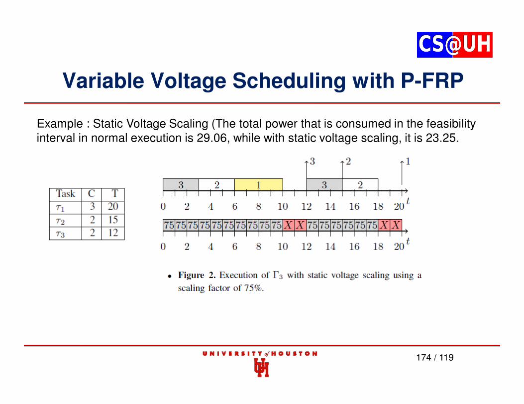
174 / 119
Example : Static Voltage Scaling (The total power that is consumed in the feasibility interval in normal execution is 29.06, while with static voltage scaling, it is 23.25.
Variable Voltage Scheduling with P-FRP
175 / 119
Example : Static Voltage Scaling (If the voltage is scaled to 50%, the first job of 1 will have a deadline miss at time 20).
Variable Voltage Scheduling with P-FRP
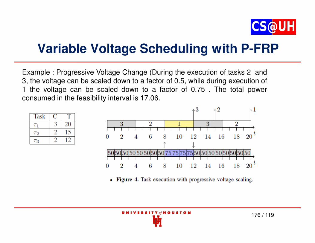
176 / 119
Example : Progressive Voltage Change (During the execution of tasks 2 and3, the voltage can be scaled down to a factor of 0.5, while during execution of1 the voltage can be scaled down to a factor of 0.75 . The total powerconsumed in the feasibility interval is 17.06.
Variable Voltage Scheduling with P-FRP
177 / 119
Example : The figure below shows the level-1 idle periods. The black areasidentify those idle periods present in the feasibility interval.
Variable Voltage Scheduling with P-FRP
178 / 119
Example : Voltage Scaling Points (The total power that is consumed is 17.25)
Variable Voltage Scheduling with P-FRP
179 / 119
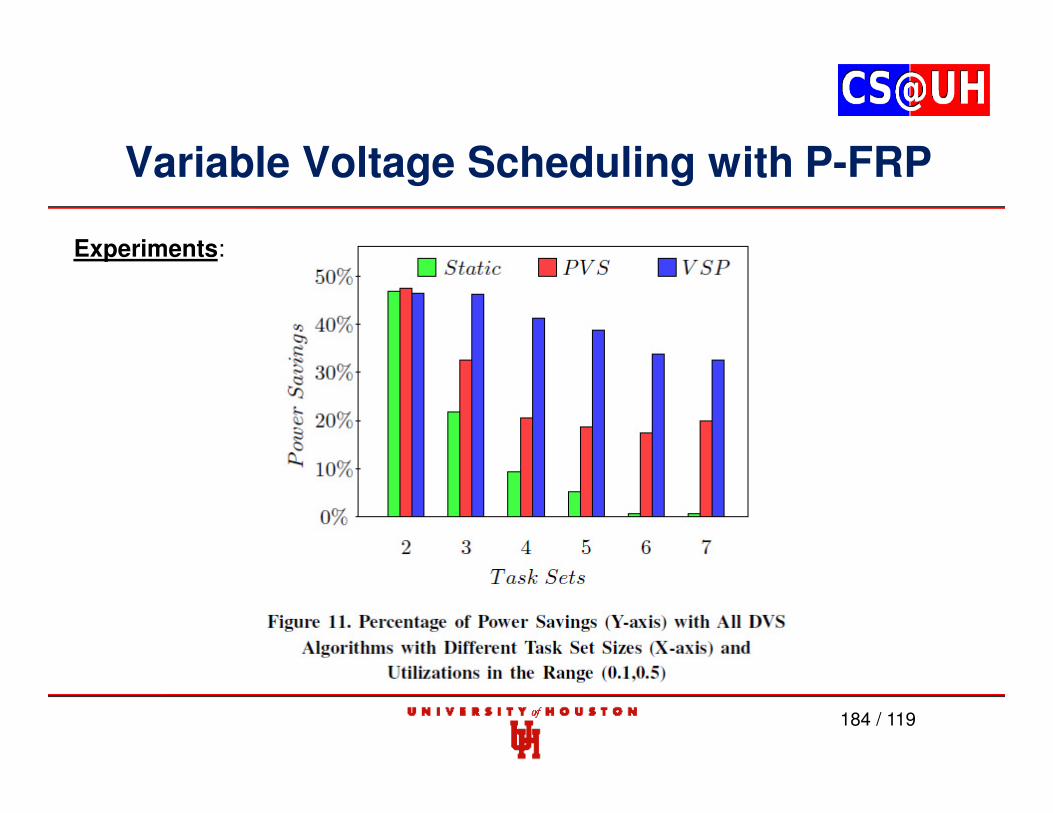
Experiments:
Tested from 100 to 500 task sets with different configurations.
Utilization factors for these tasks were in the range [0:22 to 0:65] and execution times and arrival periods were selected from the ranges [3 to 70] respectively.
Variable Voltage Scheduling with P-FRP
180 / 119
Experiments: For the static voltage scaling, 15% to 25% savings was achieved for maximum task sets.
Variable Voltage Scheduling with P-FRP
181 / 119
Experiments: PVS produced a more distributed range, with voltage savingsfor 500 task sets in the range of 0-52%.
Variable Voltage Scheduling with P-FRP
182 / 119
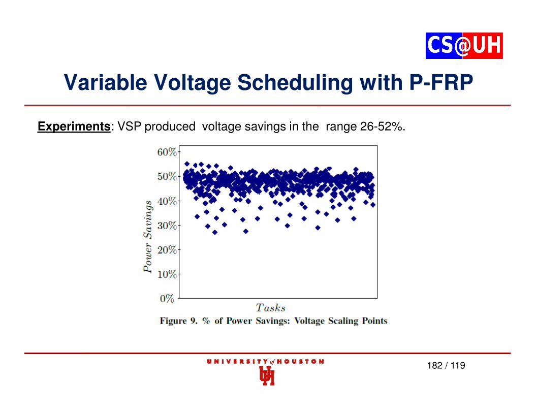
Experiments: VSP produced voltage savings in the range 26-52%.
Variable Voltage Scheduling with P-FRP
183 / 119
Experiments:
Variable Voltage Scheduling with P-FRP
184 / 119
Experiments:
Remarks
• DVFS can lead to significant energy savings
• VSP gives the best results
• Did not consider leakage current
• Chaitanya Belwal and Albert M. K. Cheng, “Optimizing Energy Use in P-FRP through Dynamic Voltage Scaling”, 17th IEEE Real-Time and Embedded Technology and Applications Symposium (RTAS) WIP Session, Chicago, IL, USA, part of the Cyber-Physical Systems Week (CPS Week), April 11-14, 2011
Contents
1. P-FRP and Real-time Systems background
2. Actual Response Time
3. Worst-case Response Time (WCRT) through Exhaustive Enumeration
4. Approximating WCRT in polynomial time
5. Feasibility Interval
6. Optimal Priority Assignments
7. Utilization Bounds
8. Partitioned Scheduling in Multi-processor Systems
9. Dynamic Voltage and Frequency Scaling
10. Response Time through Timed Automata
11. Response Time through Time Petri Nets
Contributions
• Developed Timed Automata (TA) models for schedulability analysis of P-FRP
• Prove that TA models offers an efficient alternative for schedulability analysis of P-FRP
• Use a publicly available tool for TA modeling
• Validate correctness through experimental task sets
Timed Automata
• Developed by Alur and Dill in 1994
• Extends finite state automata by using clocks
• Extended Timed Automata (ETA): states represent the execution of tasks (Fersman et al)
• ETA - standard for representing schedulability models using Timed Automata
• Used in this work
UPPAAL
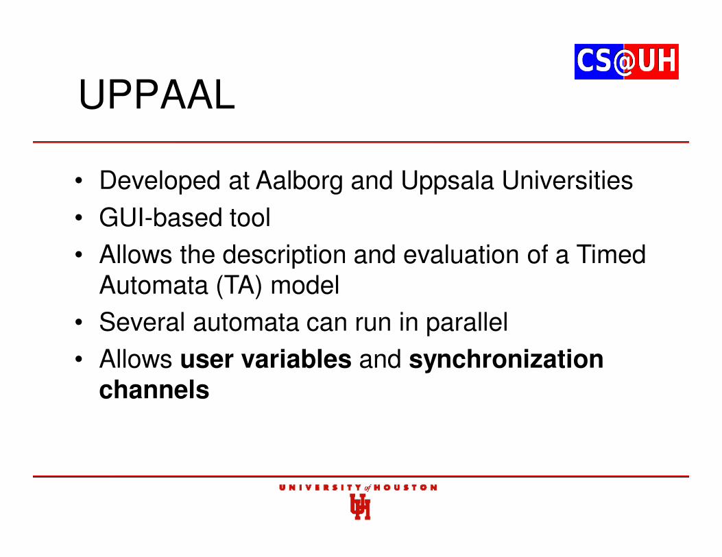
• Developed at Aalborg and Uppsala Universities
• GUI-based tool
• Allows the description and evaluation of a Timed Automata (TA) model
• Several automata can run in parallel
• Allows user variables and synchronization channels
UPPAAL
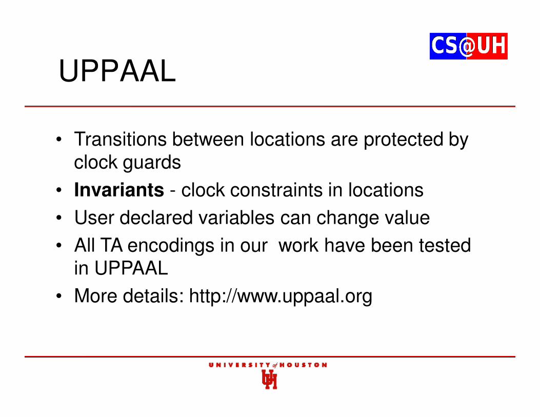
• Transitions between locations are protected by clock guards
• Invariants - clock constraints in locations
• User declared variables can change value
• All TA encodings in our work have been tested in UPPAAL
• More details: http://www.uppaal.org
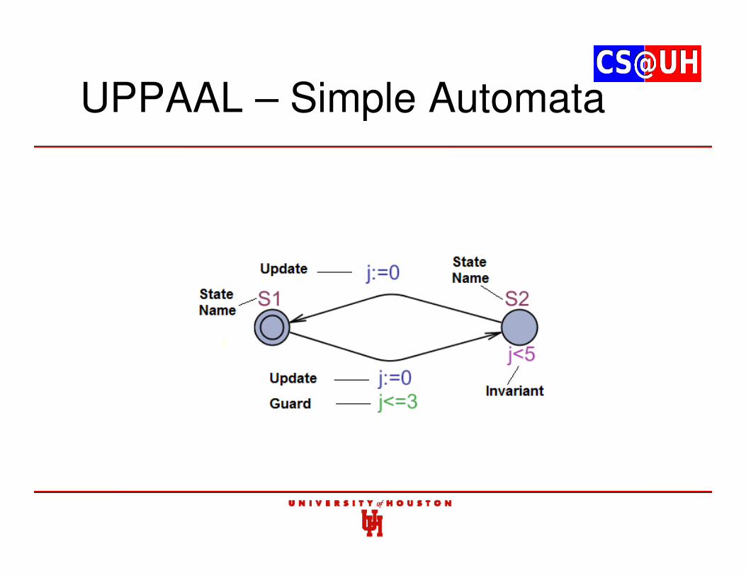
UPPAAL – Simple Automata
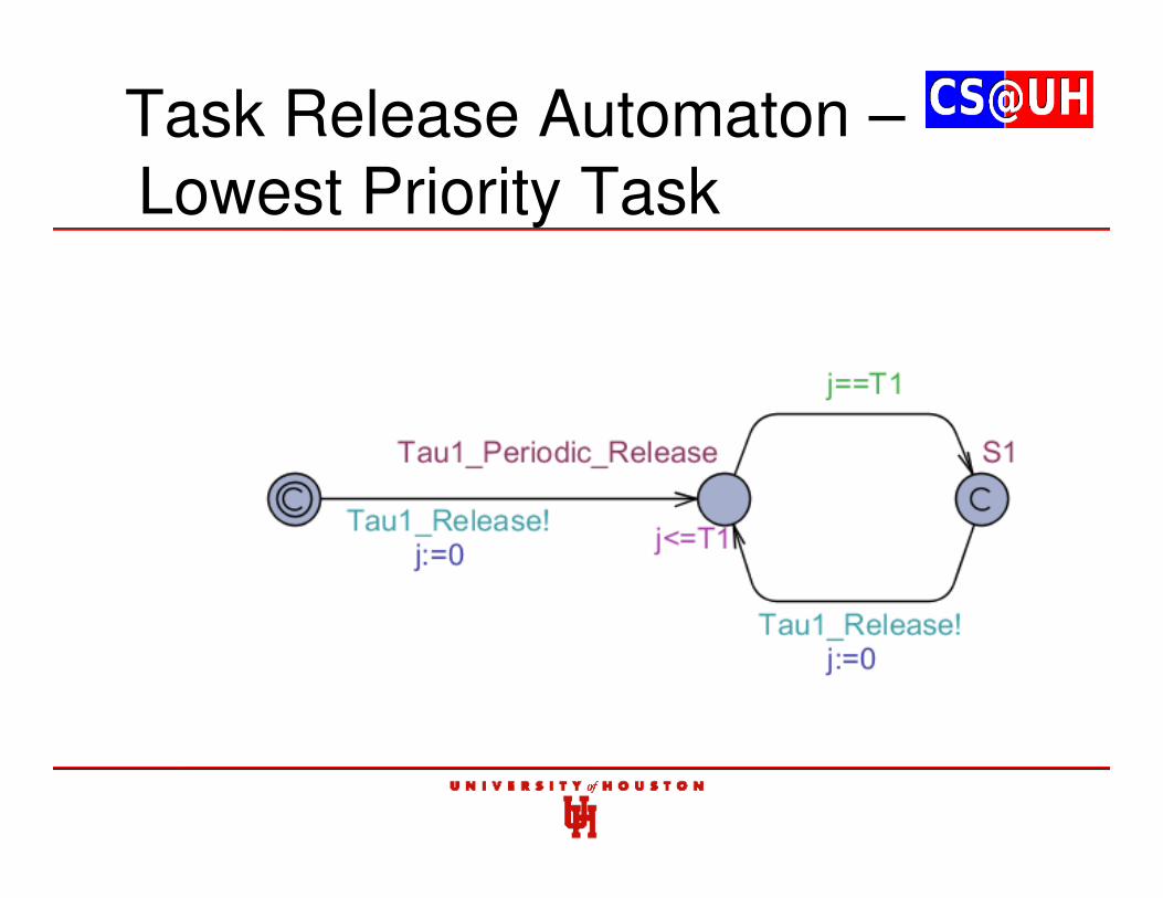
Task Release Automaton –Lowest Priority Task
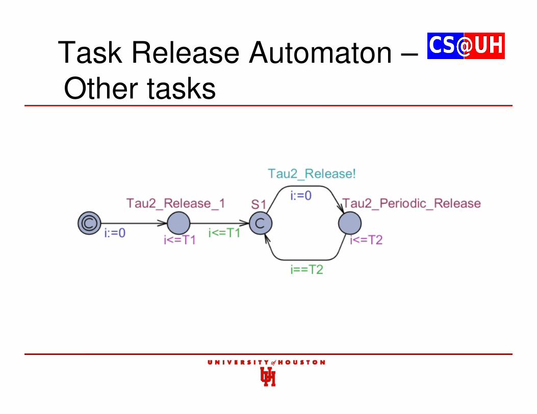
Task Release Automaton –Other tasks
Generic Variables
• GC
• cli
• Ti
• Ci
• TaujInQ
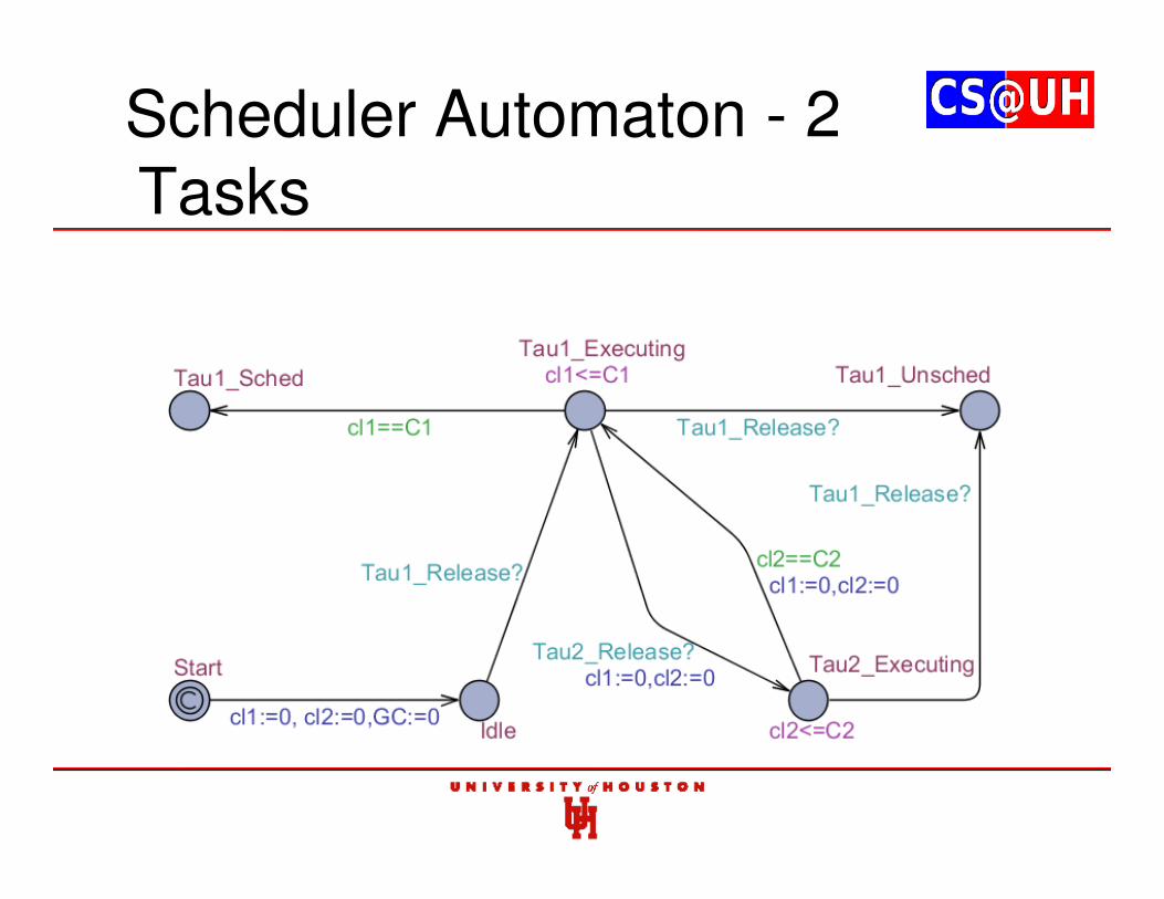
Scheduler Automaton - 2 Tasks
Scheduler Automaton - 3 Tasks
Schedulability Analysis
• Schedulability analysis is same as determining the reachability of state ‘Taui_Unsched’
• Achieved by the following Computation Tree Logic (CTL) query:
E<> Scheduler.Taui_Unsched
• Should return false for task i to be schedulable
Schedulability Analysis
• Determine the schedulability of n-task set
• Query needs to be executed for every lower priority task
• Example for the 2 task automaton following CTL should return false:
E<> Scheduler.Tau1_Unsched
• For the 3-task automaton the following queries should return false:
E<> Scheduler.Tau1_Unsched
E<> Scheduler.Tau2_Unsched
Remarks• Schedulability analysis in P-FRP is difficult
• Current techniques scales exponentially with task size
• We have derived an alternate approach using TA and validated it
• Chaitanya Belwal and Albert M. K. Cheng, “Schedulability Analysis of Transactions in Software Transactional Memory using Timed Automata”, 8th IEEE International Conference on Embedded Software and Systems (ICESS), Changsha, China, Nov. 16-18, 2011
Contents
1. P-FRP and Real-time Systems background
2. Actual Response Time
3. Worst-case Response Time (WCRT) through Exhaustive Enumeration
4. Approximating WCRT in polynomial time
5. Feasibility Interval
6. Optimal Priority Assignments
7. Utilization Bounds
8. Partitioned Scheduling in Multi-processor Systems
9. Dynamic Voltage and Frequency Scaling
10. Response Time through Timed Automata
11. Response Time through Time Petri Nets
12. Analysis Tools
Contributions
• Developed Time Petri Net (TPN) models for schedulability analysis of P-FRP
• Prove that TPN models offers an efficient alternative for schedulability analysis of P-FRP
• Prove that conversion to corresponding TA models is not required
• Use a publicly available tool for TPN modeling
• Validate correctness through experimental task sets
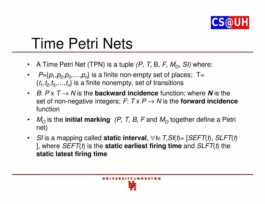
Time Petri Nets• A Time Petri Net (TPN) is a tuple (P, T, B, F, MO, SI) where:
• P={p1,p2,p3,…,pn} is a finite non-empty set of places; T= {t1,t2,t3,…,tn} is a finite nonempty, set of transitions
• B: P x T → N is the backward incidence function; where N is the set of non-negative integers; F: T x P → N is the forward incidencefunction
• MO is the initial marking (P, T, B, F and MO together define a Petri net)
• SI is a mapping called static interval, ∀t∈T,SI(t)= [SEFT(t), SLFT(t) ], where SEFT(t) is the static earliest firing time and SLFT(t) the static latest firing time
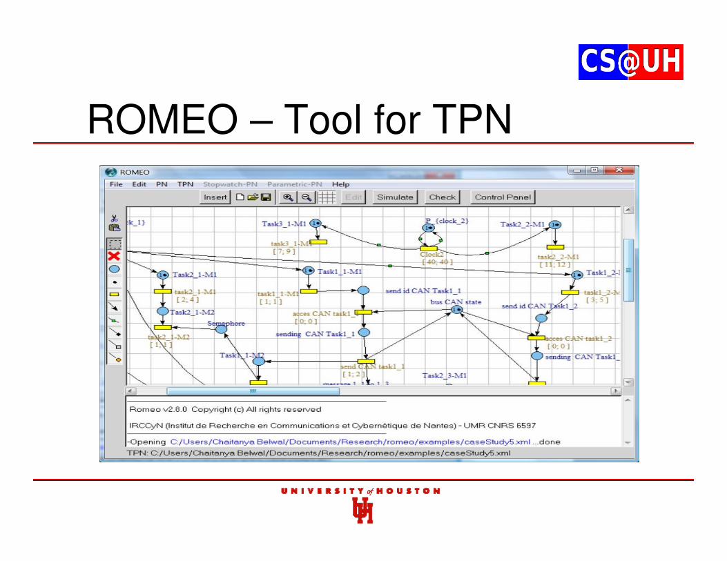
ROMEO – Tool for TPN
TPN – Periodic Task Release
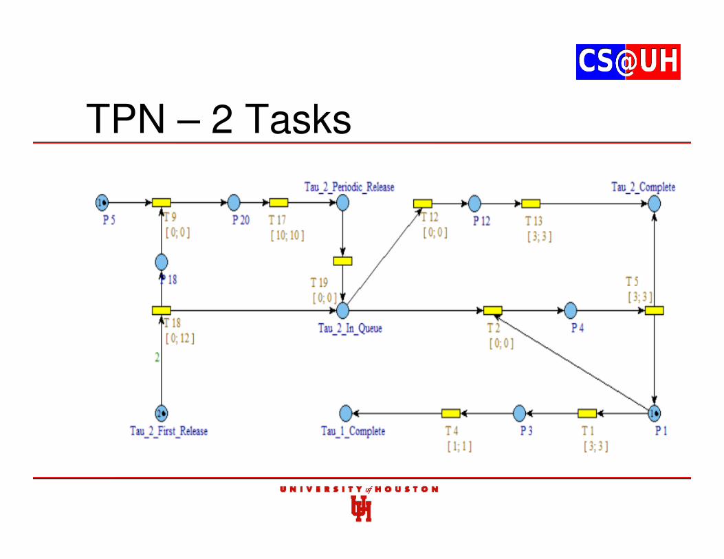
TPN – 2 Tasks
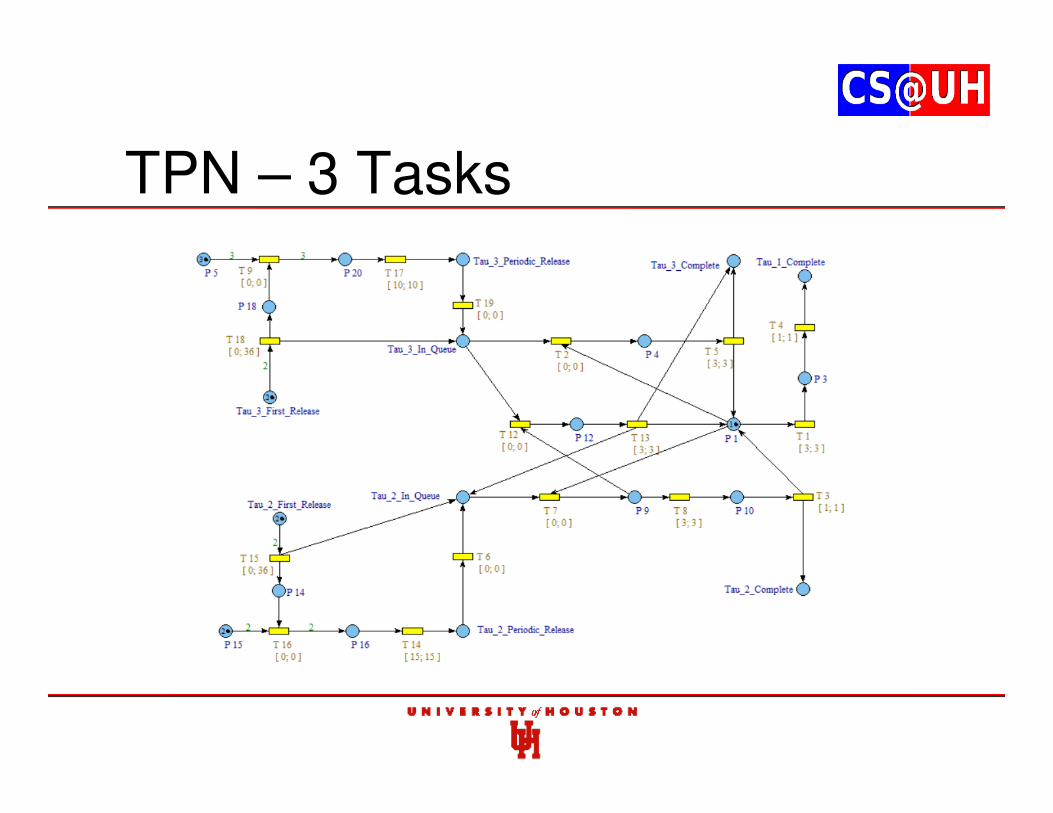
TPN – 3 Tasks
Schedulability Analysis
• TPN is converted to corresponding state space
• Uses Timed CTL queries
• EF[37,37](M(22)=0)
• At time 37 is it possible for place at index 22 (i.e. ‘Tau_1_Complete’) to have no tokens ?
• No token => release scenario of higher priority tasks exists in which τ1 misses it deadline
• For τ1 to be schedulable, the query should be false
Remarks
• TPN offers an efficient alternative to schedulability analysis
• TPNs for large models can be complicated
• Chaitanya Belwal and Albert M. K. Cheng, “Schedulability Analysis of P-FRP using Time Petri Nets”, 17th IEEE International Conference on Embedded and Real-Time Computing Systems and Applications (RTCSA) WiP Session, Toyama, Japan, August 28-31, 2011
Future Work
• Modify techniques to consider variables times for copy and restore operations
• Develop pruning techniques to reduce the number of release scenarios in determining exact WCRT
• Improve the polynomial time method for greater accuracy (lower the approximation factors)
• Develop an algorithm for finding the specific optimal priority assignment for any n-task set
• Develop global partitioning algorithms for P-FRP tasks in multi-processor platforms
Future Work
• Experimentally evaluate multi-processor partitioning schemes in hardware
• Implement DVFS algorithms in the Real-Energy platform
• Modify DVFS algorithms to consider leakage current
• Modify TA and TPN models for easier scalability
• Formally prove if exact WCRT can be determined/or not determined in polynomial time
• Extend this work to STM and lock-free execution as well as general scheduling theory (job-shop)
Evaluation
• Does precise timing characterization of the embedded controller software execution lead to faster physical system response compared with one designed without accurate controller timing analysis (and thus requires more tolerance of execution time variations)?
• How does the time to develop new control components with accurate response time analysis tools compare to doing the same with older methods?
• Automotive application: Do the new scheduling/execution such as AWR lead to safer physical system behaviors such as shorter stopping distance for ABS-equipped cars?
• Do optimizations to the runtime controller software such as reducing event-handler preemptions and better priority assignments result in faster controller response as measured by developed analytical methods, simulation, and actual physical system testing?
211 / 119
Evaluation
• Does the inclusion of power-aware and power-saving measures maintain the satisfaction of timing and space/memory constraints imposed on the embedded controller and controlled physical system behaviors? What is the amount of energy savings in the physical system and embedded controller achieved with these approaches compared with systems without them?
• Does the resulting approach make it easier and safer to make minor modifications to components of the control systems?
• Does this framework and toolset facilitate the design of the controller and its timing/safety verification? Is the time from design to actual implementation shortened and the development cost lowered?
212 / 119
Concluding Remarks
• Our goal: Enhance the safety and performance of a physical system controlled by an embedded controller consisting of single or networked control components with functional reactive programming (FRP).
• FRP allows intuitive specification and formal verification of safety-critical behaviors, thus reducing the number of defects injected during the design phase, and the stateless nature of execution avoids the need for complex programming involving synchronization primitives.
• Accurate response time analysis tools (accounting for CPU execution, memory access, I/O, and sensor processing times), novel scheduling techniques, and new power-conserving methods are needed.
• Research impact: Facilitate the design and update of the embedded controller (or network of controllers) as well as its (their) timing and safety verification.
213 / 119
Faculty Seminar
Albert M. K. Cheng
214 / 119
Thank you!
Comments?Questions?
215 / 119
References (1)
• Andrei S., Mozahid H., and Cheng A.M.K., "Optimizing the Linear Real-Time LogicVerifier,'' 19th IEEE Real-Time and Embedded Technology and ApplicationsSymposium (RTAS) WIP Session, Philadelphia, PA, April 8, 2013.
• Andrei S. and Cheng A.M.K., "Decomposition-based Verification of Linear Real-TimeSystems Specifications,'' 2nd Workshop on Compositional Theory and Technology forReal-Time Embedded Systems (CRTS), Washington, D.C., USA (Co-located withIEEE RTSS 2009), December 1, 2009.
• Andrei S. and Cheng A.M.K., "Efficient Verification and Optimization of Real-TimeLogic Specified Systems,'' IEEE Transactions on Computers, vol. 58, no. 12, pp.1640-1653, December 2009.
• Andrei S., Chin W., Lupa M., Cheng A.M.K., "Automatic Debugging of Real-TimeSystems Based on Incremental Satisfiability Counting,'' IEEE Transactions onComputers, Vol. 55, No. 7, pp. 830-843, July 2006. Selected as this issue's featuredarticle.
• Andrei S., Mozahid H., and Cheng A.M.K., Optimizing the Linear Real-Time LogicVerifier,'' 19th IEEE Real-Time and Embedded Technology and ApplicationsSymposium (RTAS) WIP Session, Philadelphia, PA, April 8, 2013.
216 / 119
References (2)
• Andrei S., Radulescu V., McNicholl T., Cheng A.M.K., "Toward an optimal power-aware scheduling technique,'' 14th International Symposium on Symbolic andNumeric Algorithms for Scientific Computing (SYNASC), Timisoara, Romania,September 26-29, 2012.
• Belwal C. and Cheng A.M.K., "Chaitanya Belwal, Albert M. K. Cheng, and Bo Liu, ``Feasibility Interval for the Transactional Event Handlers of P-FRP,'' Special Issue onUbiSafe Computing and Communications, Elsevier's Journal of Computer andSystem Sciences, 2012.
• Belwal C. and Cheng A.M.K., "Determining Actual Response Time in P-FRP," Proc.Thirteenth International Symposium on Practical Aspects of Declarative Languages(PADL), Austin, Texas, USA, pages: 250-264, January 24-25, 2011.
• Belwal C. and Cheng A.M.K., "Determining Actual Response Time in P-FRP usingIdle-Period Game Board," Proc. 14th IEEE International Symposium on Object,Component, and Service-Oriented Real-time Distributed Computing (ISORC),Newport Beach, CA, USA, pages: 136-143, March 28-31, 2011.
217 / 119
References (3)
• Belwal C. and Cheng A.M.K., "Response Time Bounds for Event Handlers in thePriority-based Functional Reactive Programming (P-FRP) Paradigm," ACM Researchin Applied Computation Symposium (RACS), San Antonio, Texas, USA, October 23-26,2012.
• Cheng A.M.K, Niktab H., and Walston M., "Timing Analysis of Small AircraftTransportation System (SATS),'' International Conference on Embedded and Real-Time Computing Systems and Applications (RTCSA), Seoul, Korea, August 2012.
• Ras J. and Cheng A.M.K., "Response Time Analysis of the Abort-and-Restart Modelunder Symmetric Multiprocessing." The 7th IEEE International Conferences onEmbedded Software and Systems (ICESS-10)," pages: 1954-1961, 2010.
• Ras J. and Cheng A.M.K., "Response Time Analysis for the Abort-and-Restart EventHandlers of the Priority-Based Functional Reactive Programming (P-FRP) Paradigm,"Embedded and Real-Time Computing Systems and Applications (RTCSA-09), pages:305-314, 2009.
218 / 119
References (4)
• Ras J. and Cheng A.M.K., "An Evaluation of the Dynamic and Static MultiprocessorPriority Ceiling Protocol and the Multiprocessor Stack Resource Policy in an SMPSystem," Proc. IEEE-CS Real-Time and Embedded Technology and ApplicationsSymposium (RTAS), San Francisco, California, April 2009.
• Wen Y., Liu Z., Shi W., Jiang Y., Yang F., Kohar A., Cheng A.M.K., "Support for PowerEfficient Mobile Video Playback on Simultaneous Hybrid Display,'‘ 10th IEEESymposium on Embedded Systems for Real-Time Multimedia Tampere, Finland,October 11-12, 2012.
• Wen Y., Belwal C., Cheng A.M.K., "Response Time Bounds for Event Handlers in thePriority based Functional Reactive Programming (P-FRP) Paradigm,'' ACM Researchin Applied Computation Symposium (RACS), San Antonio, Texas, 2012.
• Wen Y., Belwal C., Cheng A.M.K., "Time Petri Nets for Schedulability Analysis of theTransactional Event Handlers of P-FRP,'' ACM Research in Applied ComputationSymposium (RACS), San Antonio, Texas, USA, October 23-26, 2012.
• Li Y. and Cheng A.M.K., "Static Approximation Algorithms for Regularity-basedResource Partitioning,'' 33rd Real-Time Systems Symposium (RTSS), San Juan,Puerto Rico, USA, December 4-7, 2012.
219 / 119
References (5)
• Chaitanya Belwal, Yuanfeng Wen and Albert M. K. Cheng, ``Utilization Bounds of P-FRP Tasks,'' to appear in International Journal of Embedded Systems, 2013.
• Yong woon Ahn, Albert M. K. Cheng, Jinsuk Baek, Minho Jo, and Hsiao-Hwa Chen, ``An Auto-Scaling Mechanism for Virtual Resources to Support Mobile, Pervasive, Real-Time, Healthcare Applications in Cloud Computing,'' IEEE Network, Sept. 2013.
• Chaitanya Belwal, Albert M. K. Cheng, and Bo Liu, `` Feasibility Interval for the Transactional Event Handlers of P-FRP,'' Special Issue on UbiSafe Computing and Communications, Elsevier's Journal of Computer and System Sciences, Volume 79, Issue 5, pages 530-541, August 2013.
• Yuanfeng Wen, Chaitanya Belwal, and Albert M. K. Cheng, ``Towards Optimal Priority Assignments for the Transactional Event Handlers of P-FRP,'' ACM International Conference on Reliable And Convergent Systems (RACS), Montreal, QC, Canada, October 1-4, 2013.
• Chaitanya Belwal, Albert M. K. Cheng, J. Ras, and Yuanfeng Wen, ``Variable Voltage Scheduling with the Priority-based Functional Reactive Programming Language,'' ACM International Conference on Reliable And Convergent Systems (RACS), Montreal, QC, Canada, October 1-4, 2013.


![ECE Professional Seminar.ppt [Read-Only]](https://static.documents.pub/doc/80x56/61efbcea58f2216ece4d9321/ece-professional-read-only.jpg)


