+ All Categories
Home > Documents > Ultra-long Subsea Power Transmission Using …mcedd.com/wp-content/uploads/Truls Normann -...

Ultra-long Subsea Power Transmission Using …mcedd.com/wp-content/uploads/Truls Normann -...

Date post: 15-Mar-2020
Category:
Upload: others
View: 7 times
Download: 2 times
Share this document with a friend
18
© 2014 Aker Solutions Preferred partner Reliable subsea power solutions 10 March, 2014 Aker Solutions' subsea business Slide 1 Ultra-long Subsea Power Transmission Using Frequency Step-up Equipment MCE Deepwater Development 2014 – Madrid, Spain – 9 April 2014 Truls Normann | First Chief Engineer – Subsea Power Products & Technology
Transcript

© 2014 Aker Solutions Preferred partner

Preferred partner

Reliable subseapower solutions

10 March, 2014 Aker Solutions' subsea businessSlide 1

Ultra-long Subsea Power TransmissionUsing Frequency Step-up Equipment

MCE Deepwater Development 2014 – Madrid, Spain – 9 April 2014

Truls Normann | First Chief Engineer – Subsea Power Products & Technology

Public © 2014 Aker Solutions Preferred partner

Subsea Power – Enabling Increased Oil & Gas Recovery

■ Type 1■ Topside VSDs

■ Type 2■ Topside VSDs■ Subsea transformers

■ Type 3■ Subsea VSDs■ Subsea Switchgear

■ Type 4■ Low Frequency AC■ 4a – Topside VSDs■ 4b – Subsea VSDs

■ HVDC not covered■ No connectors■ No switchgear■ Too large subsea■ N/A next 5-10 years

■ High power■ Exists for < 10kV /

<10kWSlide 2© 2014 Aker Solutions

Public © 2014 Aker Solutions Preferred partner

BP King MultiBooster

■ 2x 1MW 6.6kV

■ 2x 2.5MVA VSDs

■ 24km & 28km

■ 1600m and 1700m

Power System Type 1 BP King MultiBooster™

Qualifiedfor 3000m

Slide 3© 2014 Aker Solutions

Public © 2014 Aker Solutions Preferred partner

VSDBuilding40MVA totalpower

Power System Type 2 Åsgard Subsea Compression

Qualifiedfor 300m& 3000m

Compressor Trafo

Pump & CPDUTrafo

CPDU(control power

distribution unit)

CompressionStation

Slide 4© 2014 Aker Solutions

Public © 2014 Aker Solutions Preferred partner

30MW / 22kV Circuit Breaker Module 16MVA Compressor VSD Module

Power System Type 3 Ormen Lange Pilot

PrototypesQualifiedfor 900m

500kVA PumpVSD Module

160kVA UPSModules A & B

Slide 5© 2014 Aker Solutions

Public © 2014 Aker Solutions Preferred partner

Low Frequency ACTransmission Stability

50Hz

100Hz

Solution:- Reduce transmission frequency

→ Less charging currents

→ Longer step-out

Maximum Power Transfer at 16.7Hz & 50Hz

3x1x240mm2 cables

Low Frequency ACPower Transfer Capability

Slide 6© 2014 Aker Solutions

Public © 2014 Aker Solutions Preferred partner

Power System Type 4

RotoConverter™ - Low Frequency AC for Long Step-out

Patented RotoConverter™

■ Electrical gear● 10-20Hz transmission● 50-200Hz generator

■ Reduces cable ageing due tolow frequency

■ More MW, longer step-out

■ Works as harmonic filter (due tomass) and phase compensator

■ Low weight/size

■ Pressure compensated

■ Robust due to low mech. speed

Slide 7© 2014 Aker Solutions

Public © 2014 Aker Solutions Preferred partner

LFAC RotoConverter™ for Subsea Control Systems

Control Power Supply

■ LFAC● 3-ph or single phase● More power● Longer step-out● Smaller cables● An alternative to DC

■ Lower transmission voltage● Less cable / connector

stresses

Slide 8© 2014 Aker Solutions

Public © 2014 Aker Solutions Preferred partner

RotoConverter™ 70kVA/50kW Prototype

PM Motor

PM Generator

70kVA/50kW RotoConverter™• For Subsea Control Systems• Permanent Magnet Motor• 16.7Hz input / transmission frequency• Permanent Magnet Generator• 50Hz 50kW output / load motor

Slide 9

Conventional industry / Railway rotating converter design

© 2014 Aker Solutions

Public © 2014 Aker Solutions Preferred partner

70kVA/50kW Subsea RotoConverter™ during FAT

Slide 10© 2014 Aker Solutions

Subsea RotoConverter™ during high voltage testing

Subsea RotoConverter™ during MC checks

Public © 2014 Aker Solutions Preferred partner

RotoConverter™ – Prototype Design and Analysis

■ Analytically proven:■ Load flow and short circuit■ Start-up■ Harmonics■ Dynamic load changes

■ Verified by:■ Sintef Energy Research (3rd party)■ Aker Solutions■ PMSM - PMSG Supplier / Smart Motor

■ 70kVA/50 kW unit test will lift the technology readiness level to:■ TRL to 4 for small units (<100kVA)■ TRL to 2 for large units (>10MVA)

Slide 11© 2014 Aker Solutions

Stator slot thermal analysisVon Mises stress plot of motor rotor

Public © 2014 Aker Solutions Preferred partner

Example 1: Subsea Pump Test Set-up and Model

• Scale model with 200km step-out cable simulator- 16.7Hz transmission frequency

• 50kW output PMSM-PMSG RotoConverter™- 50Hz / 50kW pump load / static control load

Slide 12© 2014 Aker Solutions

VSD

50kW70kVA

Public © 2014 Aker Solutions Preferred partner

Example 1: Start-up Simulations – Results 200kmPermanent Magnet Motor Permanent Magnet Generator Induction Motor

Slide 13© 2014 Aker Solutions

Proof: Works well at 16.7Hz and not at 50Hz!

Public © 2014 Aker Solutions Preferred partner

RotoConverter™ Development Status

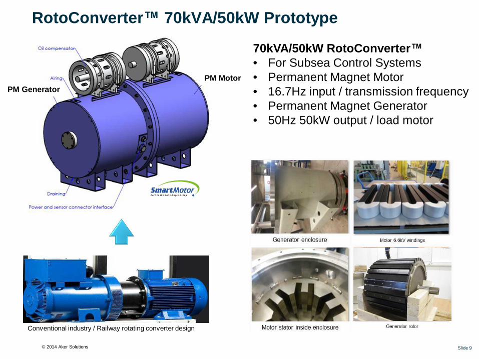
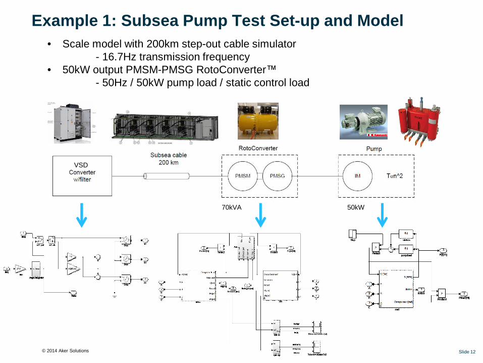
■ 70kVA/50kW Prototype FAT completed■ System test to start Q2 2014■ Test with cable simulator H2 2014

■ Joint Industry Project (JIP) planning for launch on-going■ Identify business case / test field application■ 8MVA/6MW prototype design, construction and qualification test

■ 8MVA/6MW Prototype qualification planned to be completed 1.5-2 years after JIP start

Concept Select Engineering & DesignProcurement &

ConstructionProof of Concept

Testing

2013 2014

Slide 14© 2014 Aker Solutions

Public © 2014 Aker Solutions Preferred partner

8MVA RotoConverter™ for 6MW Compressors / PumpsKey data:

■ RotoConverter™ Unit■ Weight = 35T■ LxD = 3.5m x 2.3m

■ Module:■ Weight = 50T■ LxWxH = 5.0 x 4.0 x 6.5 m

■ HV jumper routing decides height

■ Power for 6MW Compressor (example)■ Input:

■ 8MVA / 6.5MW■ 19Hz■ 6.6kV (can be higher /

“RotoTransformer”)

■ Output:■ 7MVA / 6MW■ 210Hz■ 6.6kV

■ RotoConverter™ shaft speed■ Approx 300 rpm■ Oil-filled■ Low losses due to speed

Slide 15© 2014 Aker Solutions

Public © 2014 Aker Solutions Preferred partner

LFAC / RotoConverter™ – Summary of Subsea Advantages

• Less charging currents and power losses

• Less voltage variations

• Works as phase compensator and harmonic filter

• Eliminates need for subsea VSD for more prospects

• Subsea HV and high power up to 50MW and beyond

• Subsea LV and control power typically <100kW

• Reduced subsea modules and equipment CAPEX

More power / MW @ longer distances1

Reduced transmission frequency2

• Smaller cables → less copper

• Increased transmission cable robustness / lifetime

• Ultra-long step-out

• Reduced cable CAPEX

Better power system stability3

Slide 16© 2014 Aker Solutions

Public © 2014 Aker Solutions Preferred partner10 March, 2014Slide 17

Thank you for your attention!

Truls NormannFirst Chief Engineer (M.Sc)Head of Power Products & Technology | Power & Process

Tel: +47 67 82 60 00E-mail: [email protected] | www.akersolutions.com

Aker Subsea ASVisiting address: Snarøyveien 36, 1365 Fornebu, NorwayPostal address: PO Box 94, 1325 Lysaker, NorwayRegistered in Norway, registration no. 929 877 950 VAT

Public © 2014 Aker Solutions Preferred partner

Copyright and disclaimer

CopyrightCopyright of all published material including photographs, drawings and images in this document remains vested in Aker Solutions andthird party contributors as appropriate. Accordingly, neither the whole nor any part of this document shall be reproduced in any form norused in any manner without express prior permission and applicable acknowledgements. No trademark, copyright or other notice shallbe altered or removed from any reproduction.

DisclaimerThis Presentation includes and is based, inter alia, on forward-looking information and statements that are subject to risks anduncertainties that could cause actual results to differ. These statements and this Presentation are based on current expectations,estimates and projections about global economic conditions, the economic conditions of the regions and industries that are majormarkets for Aker Solutions ASA and Aker Solutions ASA’s (including subsidiaries and affiliates) lines of business. These expectations,estimates and projections are generally identifiable by statements containing words such as “expects”, “believes”, “estimates” or similarexpressions. Important factors that could cause actual results to differ materially from those expectations include, among others,economic and market conditions in the geographic areas and industries that are or will be major markets for Aker Solutions’ businesses,oil prices, market acceptance of new products and services, changes in governmental regulations, interest rates, fluctuations in currencyexchange rates and such other factors as may be discussed from time to time in the Presentation. Although Aker Solutions ASA believesthat its expectations and the Presentation are based upon reasonable assumptions, it can give no assurance that those expectations willbe achieved or that the actual results will be as set out in the Presentation. Aker Solutions ASA is making no representation or warranty,expressed or implied, as to the accuracy, reliability or completeness of the Presentation, and neither Aker Solutions ASA nor any of itsdirectors, officers or employees will have any liability to you or any other persons resulting from your use.

Aker Solutions consists of many legally independent entities, constituting their own separate identities. Aker Solutions is used as thecommon brand or trade mark for most of these entities. In this presentation we may sometimes use “Aker Solutions”, “we” or “us” whenwe refer to Aker Solutions companies in general or where no useful purpose is served by identifying any particular Aker Solutionscompany.

Slide 18 10 March, 2014


Recommended