132

Understanding RF Fundamentals and the Radio Design of Wireless Networks
Session BRKEWN-2017
EDCS-1403259
Fred Niehaus N8CPI – Technical Marketing Engineer
Wireless Networking Group
Email [email protected]
© 2014 Cisco and/or its affiliates. All rights reserved. BRKEWN-2017 Cisco Public
Session Abstract
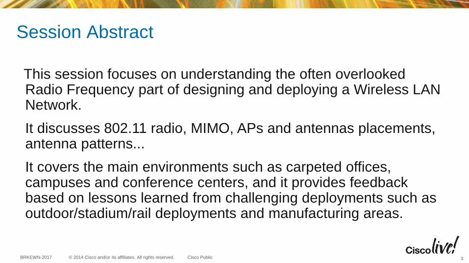
This session focuses on understanding the often overlooked Radio Frequency part of designing and deploying a Wireless LAN Network.
It discusses 802.11 radio, MIMO, APs and antennas placements, antenna patterns...
It covers the main environments such as carpeted offices, campuses and conference centers, and it provides feedback based on lessons learned from challenging deployments such as outdoor/stadium/rail deployments and manufacturing areas.
3

© 2014 Cisco and/or its affiliates. All rights reserved. BRKEWN-2017 Cisco Public
Session Agenda – Objectives
• What is radio and how did we get here?
• Basic 802.11 Radio Hardware & Terminology
• Antenna Basics – Single, Dual Band and MIMO Antennas
• Interpreting antenna patterns
• Understanding fundamentals of, Beam-forming and Cisco ClientLink
• Basic understanding of 802.11n and 802.11ac fundamentals including MIMO, Channel bonding, Multi-path, Spatial Streams etc.
• Installation challenges, when to use different APs – avoiding potential problems
4

© 2014 Cisco and/or its affiliates. All rights reserved. BRKEWN-2017 Cisco Public
What We Won’t Be Covering
• Wireless Security (dedicated sessions for that)
• Clean Air (separate sessions for that)
• wIDS/wIPS (Wireless Intrusion Prevention Systems)
• High density deployments (separate session for that)
• LBS (Location Based Services) or Context Aware
• Walled garden, captive portals
• SP Wi-Fi, 3G offload and HotSpot 2.0
• WLAN management
• 802.11n going beyond RF characteristics
5

What is Radio? How did we end up on these Frequencies?

© 2014 Cisco and/or its affiliates. All rights reserved. BRKEWN-2017 Cisco Public
Basic Understanding of Radio…
Battery is DC
Direct Current Typical home is AC
Alternating Current
AC Frequency 60 Hz or 60
CPS – Cycles Per Second Waves travel back and forth so fast
they actually leave the wire
Popular Radio
Frequencies: AM Radio 520-1610 KHz
Shortwave 3-30 MHz
FM Radio 88 to 108 MHz
Aviation 108-121 MHz
Weather Radio 162.40 MHz
GSM Phones 900 & 1800 MHz
DECT Phones 1900 MHz
Wi-Fi 802.11b/g/n 2.4 GHz
Wi-Fi 802.11a/n 5 GHz
How fast the AC current goes, is its “frequency”
AC is very low frequency 50-60 Hz (Cycles Per Second)
Radio waves are measured in kHz, MHz and GHz
The lower the frequency, the physically longer the radio wave –
Higher frequencies have much shorter waves, and as such, it
takes more power to move them greater distances.
This is why 2.4 GHz goes further vs. 5 GHz
(given same amount of RF power). 7
Spark transmitter
© 2014 Cisco and/or its affiliates. All rights reserved. BRKEWN-2017 Cisco Public
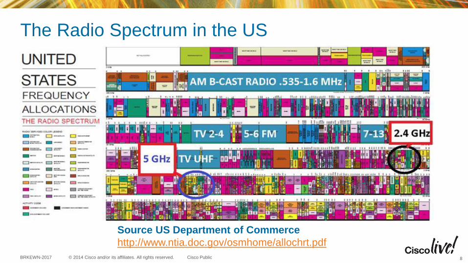
The Radio Spectrum in the US
Source US Department of Commerce
http://www.ntia.doc.gov/osmhome/allochrt.pdf
8
© 2014 Cisco and/or its affiliates. All rights reserved. BRKEWN-2017 Cisco Public
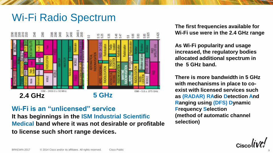
Wi-Fi Radio Spectrum
Wi-Fi is an “unlicensed” service It has beginnings in the ISM Industrial Scientific
Medical band where it was not desirable or profitable
to license such short range devices.
The first frequencies available for
Wi-Fi use were in the 2.4 GHz range
As Wi-Fi popularity and usage
increased, the regulatory bodies
allocated additional spectrum in
the 5 GHz band.
There is more bandwidth in 5 GHz
with mechanisms in place to co-
exist with licensed services such
as (RADAR) RAdio Detection And
Ranging using (DFS) Dynamic
Frequency Selection
(method of automatic channel
selection)
2.4 GHz 5 GHz
9
© 2014 Cisco and/or its affiliates. All rights reserved. BRKEWN-2017 Cisco Public
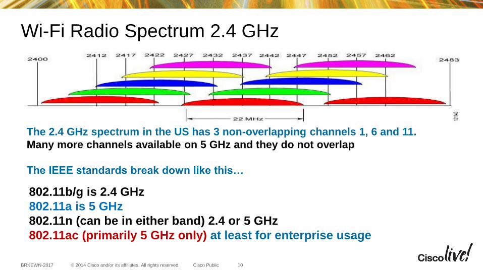
Wi-Fi Radio Spectrum 2.4 GHz
The 2.4 GHz spectrum in the US has 3 non-overlapping channels 1, 6 and 11.
Many more channels available on 5 GHz and they do not overlap
The IEEE standards break down like this…
10
802.11b/g is 2.4 GHz
802.11a is 5 GHz
802.11n (can be in either band) 2.4 or 5 GHz
802.11ac (primarily 5 GHz only) at least for enterprise usage

© 2014 Cisco and/or its affiliates. All rights reserved. BRKEWN-2017 Cisco Public
Wi-Fi Radio Spectrum 5 GHz Channels
Note: 5 GHz channels do
not have the overlap that
2.4 GHz channels have but
they often use DFS
(Dynamic Frequency
Selection) to enable
sharing of the band
11
Lots of channels more on this later…
© 2014 Cisco and/or its affiliates. All rights reserved. BRKEWN-2017 Cisco Public
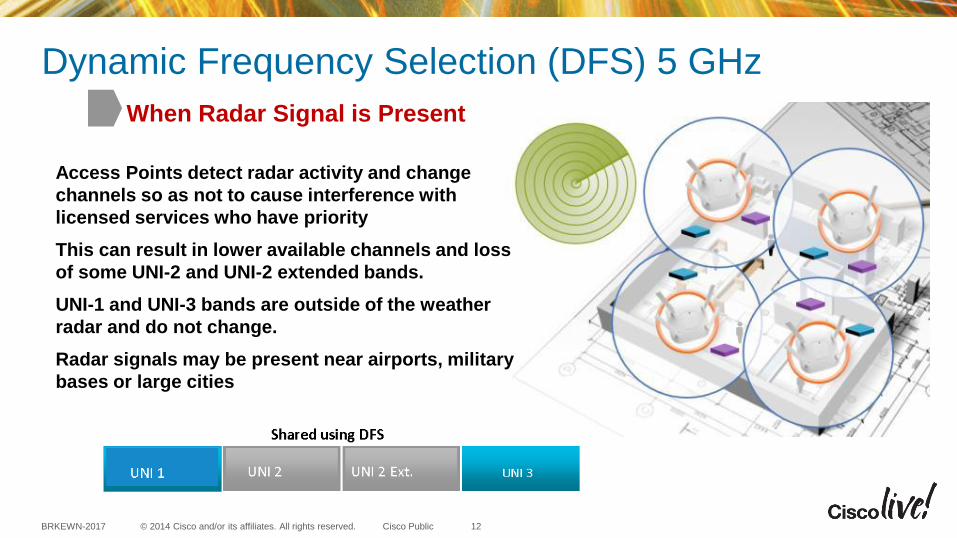
Dynamic Frequency Selection (DFS) 5 GHz
When Radar Signal is Present
Access Points detect radar activity and change
channels so as not to cause interference with
licensed services who have priority
This can result in lower available channels and loss
of some UNI-2 and UNI-2 extended bands.
UNI-1 and UNI-3 bands are outside of the weather
radar and do not change.
Radar signals may be present near airports, military
bases or large cities
UNI 1 UN 3
12

© 2014 Cisco and/or its affiliates. All rights reserved. BRKEWN-2017 Cisco Public
Complex Modulation Schemes Radio technology has a lot in common
with that old twisted pair phone line that
started out at 300 baud and then quickly
increased
In order to get faster data rates,
(throughput) into the radio signal,
complex high density modulation
schemes are used
Generally speaking, the faster the data
rate the more powerful the signal needs
to be at the receiver end to be properly
decoded.
Take away – more complex modulation
happens at shorter distances
High-density modulation schemes such as 64-QAM
“Quadrature Amplitude Modulation” is used by
802.11n to get additional throughput higher than what
is found in 802.11a/b/g. This is one of the advantages
of 802.11n
Note: Newer 802.11ac modes can use up to 256-QAM
Example of 802.11n Modulation Coding Schemes
13
Basic 802.11 RF Terminology Hardware identification

© 2014 Cisco and/or its affiliates. All rights reserved. BRKEWN-2017 Cisco Public
Common RF Terms • Attenuation – a loss in force or intensity – As radio waves travel in media such as coaxial cable attenuation occurs.
• BER – Bit Error Rate - the fraction of bits transmitted that are received incorrectly.
• Channel Bonding – act of combining more than one channel for additional bandwidth
• dBd – abbreviation for the gain of an antenna system relative to a dipole
• dBi – abbreviation for the gain of an antenna system relative to an isotropic antenna
• dBm – decibels milliwatt -- abbreviation for the power ratio in decibels (dB) of the measured power referenced to one milliwatt of transmitted RF power.
• Multipath – refers to a reflected signal that combines with a true signal resulting in a weaker or some cases a stronger signal.
• mW – milliwatt a unit of power equal to one thousandth of a watt (usually converted to dBm)
• Noise Floor – The measure of the signal created from the sum of all the noise sources and unwanted signals appearing at the receiver. This can be adjacent signals, weak signals in the background that don’t go away, electrical noise from electromechanical devices etc.
• Receiver Sensitivity – The minimum received power needed to successfully decode a radio signal with an acceptable BER. This is usually expressed in a negative number depending on the data rate. For example the AP-1140 Access Point requires an RF strength of at least negative -91 dBm at 1 MB and an even higher strength higher RF power -79 dBm to decode 54 MB
• Receiver Noise Figure – The internal noise present in the receiver with no antenna present (thermal noise).
• SNR – Signal to Noise Ratio – The ratio of the transmitted power from the AP to the ambient (noise floor) energy present.
For Your Reference
15
© 2014 Cisco and/or its affiliates. All rights reserved. BRKEWN-2017 Cisco Public
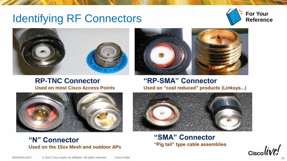
Identifying RF Connectors
RP-TNC Connector Used on most Cisco Access Points
“N” Connector Used on the 15xx Mesh and outdoor APs
“SMA” Connector “Pig tail” type cable assemblies
“RP-SMA” Connector Used on “cost reduced” products (Linksys...)
16
For Your Reference

© 2014 Cisco and/or its affiliates. All rights reserved. BRKEWN-2017 Cisco Public
Antenna Cables – LMR Series
This is a chart depicting different
types of Microwave LMR Series
coaxial cable.
Cisco uses Times Microwave cable
and has standardized on two types:
Cisco Low Loss (LMR-400)
Ultra Low Loss (LMR-600).
LMR-600 is recommended when
longer cable distances are required
Larger cables can be used but
connectors are difficult to find and
larger cable is harder to install
Trivia: LMR Stands for “Land Mobile Radio” 17
For Your Reference

© 2014 Cisco and/or its affiliates. All rights reserved. BRKEWN-2017 Cisco Public
Some Antenna Cables Characteristics
Foil shield and braid
LMR-400 3/8 inch
LMR-600 ½ inch
LMR type cable has
a Cisco P/N like
this…
AIR-CAB-050-LL-R
AIR - Aironet
CAB – Cable
050 - Length
LL - Low Loss (LMR-400)
R - RP-TNC
connector
18
For Your Reference
Antenna Basics
© 2014 Cisco and/or its affiliates. All rights reserved. BRKEWN-2017 Cisco Public
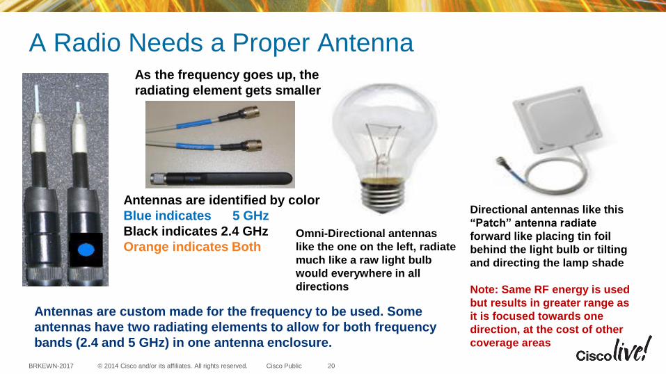
A Radio Needs a Proper Antenna
Antennas are identified by color
Blue indicates 5 GHz
Black indicates 2.4 GHz
Orange indicates Both
As the frequency goes up, the
radiating element gets smaller
Antennas are custom made for the frequency to be used. Some
antennas have two radiating elements to allow for both frequency
bands (2.4 and 5 GHz) in one antenna enclosure.
Omni-Directional antennas
like the one on the left, radiate
much like a raw light bulb
would everywhere in all
directions
Directional antennas like this
“Patch” antenna radiate
forward like placing tin foil
behind the light bulb or tilting
and directing the lamp shade
Note: Same RF energy is used
but results in greater range as
it is focused towards one
direction, at the cost of other
coverage areas
20

© 2014 Cisco and/or its affiliates. All rights reserved. BRKEWN-2017 Cisco Public
Antenna Basics
• Antenna - a device which radiates and/or receives radio signals
• Antennas are usually designed to operate at a specific frequency
• Some antennas have more than one radiating element (example Dual Band)
• Antenna Gain is characterized using dBd or dBi – Antenna gain can be measured in decibels against a reference antenna called a
dipole and the unit of measure is dBd (d for dipole) – Antenna gain can be measured in decibels against a computer modeled antenna
called an “isotropic” dipole <ideal antenna> and the unit of measure is dBi the “i” is for isotropic dipole which is a computer modeled “perfect” antenna
• WiFi antennas are typically rated in dBi. – dBi is a HIGHER value (marketing folks like higher numbers) – Conventional radio (Public safety) tend to use a dBd rating. – To convert dBd to dBi simply add 2.14 so a 3 dBd = 5.14 dBi
21
© 2014 Cisco and/or its affiliates. All rights reserved. BRKEWN-2017 Cisco Public
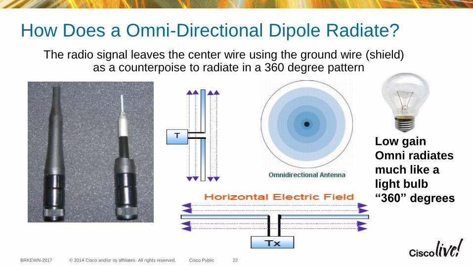
How Does a Omni-Directional Dipole Radiate?
The radio signal leaves the center wire using the ground wire (shield) as a counterpoise to radiate in a 360 degree pattern
Low gain
Omni radiates
much like a
light bulb
“360” degrees
22

© 2014 Cisco and/or its affiliates. All rights reserved. BRKEWN-2017 Cisco Public
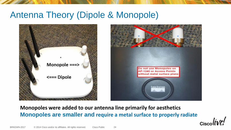
Dipole
A dipole does not require a ground
plane as the bottom half is the ground
(counterpoise).
Monopole
A Monopole requires a
ground plane –
(conductive surface)
808 Ft Broadcast Monopole
WSM 650 AM (erected in 1932)
Antenna Theory (Dipole & Monopole)
23
© 2014 Cisco and/or its affiliates. All rights reserved. BRKEWN-2017 Cisco Public
Monopoles were added to our antenna line primarily for aesthetics Monopoles are smaller and require a metal surface to properly radiate
Antenna Theory (Dipole & Monopole)
24
© 2014 Cisco and/or its affiliates. All rights reserved. BRKEWN-2017 Cisco Public
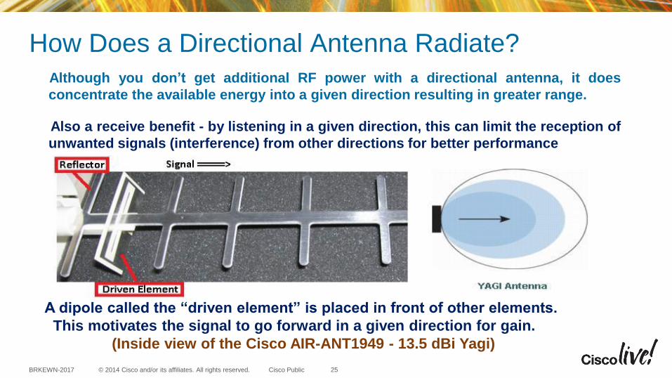
How Does a Directional Antenna Radiate? Although you don’t get additional RF power with a directional antenna, it does
concentrate the available energy into a given direction resulting in greater range.
Also a receive benefit - by listening in a given direction, this can limit the reception of
unwanted signals (interference) from other directions for better performance
A dipole called the “driven element” is placed in front of other elements.
This motivates the signal to go forward in a given direction for gain.
(Inside view of the Cisco AIR-ANT1949 - 13.5 dBi Yagi)
25

© 2014 Cisco and/or its affiliates. All rights reserved. BRKEWN-2017 Cisco Public
Patch Antenna: a Look Inside
The 9.5 dBi Patch called AIR-ANT5195-R
Patch antennas can have multiple radiating elements that combine for gain.
Sometimes, a metal plate is used behind the antenna as a reflector for more gain.
Cisco Public 26
Patch and
Yagi antennas
favor the
direction the
antenna is
pointed – like
a flashlight

© 2014 Cisco and/or its affiliates. All rights reserved. BRKEWN-2017 Cisco Public
Antennas Identified by Color
Cisco Antenna Color Coding
Black indicates
2.4 GHz
Blue indicates
5 GHz
Orange indicates
2.4 & 5 GHz (used on 1600,2600,2700,3600 &
3700 Series Access Points)
Cisco antennas & cables are color coded – Black or no markings indicate 2.4 GHz
27
For Your Reference

© 2014 Cisco and/or its affiliates. All rights reserved. BRKEWN-2017 Cisco Public
Guide to Antenna Part Numbers
28
For Your Reference

© 2014 Cisco and/or its affiliates. All rights reserved. BRKEWN-2017 Cisco Public 29
For Your Reference
Most Common 802.11n Antennas Indoor Access Points (1262 and 3502e) <First Generation AP’s>
These are Single Radiating Element antennas designed for Access Points
that have single band 2.4 or 5 GHz connectors (black or blue color)
Note: do *NOT* use on units with ORANGE label (1600, 2600, 3600)…
© 2014 Cisco and/or its affiliates. All rights reserved. BRKEWN-2017 Cisco Public 30
For Your Reference
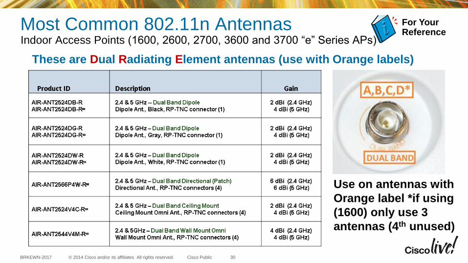
Most Common 802.11n Antennas Indoor Access Points (1600, 2600, 2700, 3600 and 3700 “e” Series APs)
Use on antennas with
Orange label *if using
(1600) only use 3
antennas (4th unused)
These are Dual Radiating Element antennas (use with Orange labels)

Understanding and Interpreting Antenna Patterns

© 2014 Cisco and/or its affiliates. All rights reserved. BRKEWN-2017 Cisco Public
The Richfield Ohio (Aironet) Facility Designs and characterizes antennas - creating the patterns you see in the spec sheets
Satimo software compatible with
Stargate-64 System. Basic
measurement tool is Agilent 8753ES
Network Analyzer.
Cisco Anechoic chamber using an 45 cm
absorber all the way, around 1-6 GHz
Anechoic means “without echo”
32
© 2014 Cisco and/or its affiliates. All rights reserved. BRKEWN-2017 Cisco Public
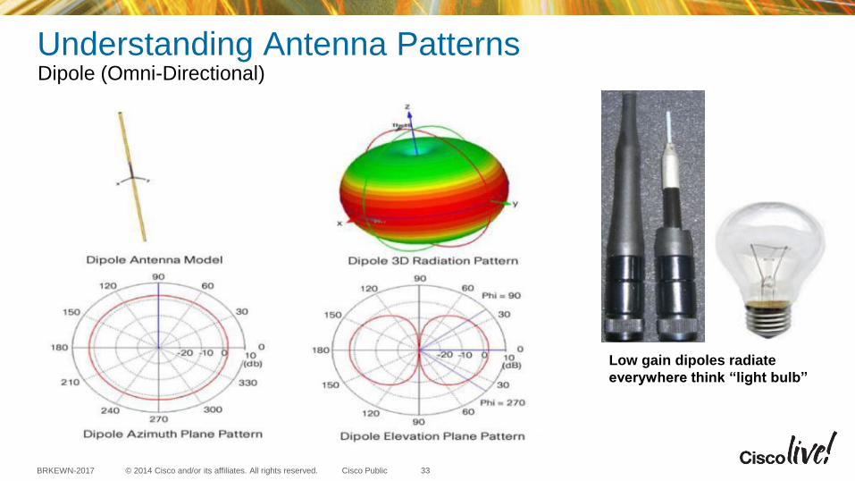
Low gain dipoles radiate
everywhere think “light bulb”
Understanding Antenna Patterns Dipole (Omni-Directional)
33
© 2014 Cisco and/or its affiliates. All rights reserved. BRKEWN-2017 Cisco Public
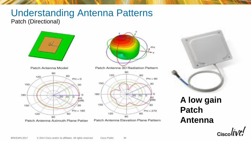
A low gain
Patch
Antenna
Understanding Antenna Patterns Patch (Directional)
34

© 2014 Cisco and/or its affiliates. All rights reserved. BRKEWN-2017 Cisco Public
A High Gain
Four element
Patch Array
Understanding Antenna Patterns Patch (Higher Gain Directional)
35

© 2014 Cisco and/or its affiliates. All rights reserved. BRKEWN-2017 Cisco Public
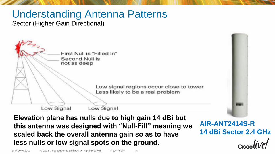
Elevation plane has nulls due to high gain 14 dBi
AIR-ANT2414S-R
14 dBi Sector 2.4 GHz
Understanding Antenna Patterns Sector (Higher Gain Directional)
36
© 2014 Cisco and/or its affiliates. All rights reserved. BRKEWN-2017 Cisco Public
AIR-ANT2414S-R
14 dBi Sector 2.4 GHz
Elevation plane has nulls due to high gain 14 dBi but
this antenna was designed with “Null-Fill” meaning we
scaled back the overall antenna gain so as to have
less nulls or low signal spots on the ground.
Understanding Antenna Patterns Sector (Higher Gain Directional)
37

Understanding Multipath Diversity and Beamforming

© 2014 Cisco and/or its affiliates. All rights reserved. BRKEWN-2017 Cisco Public
As radio signals
bounce off metal
objects they often
combine at the receiver
This often results in
either an improvement
“constructive” or a
“destructive” type of
interference
Note: Bluetooth type radios that “hop” across the entire band can reduce multipath
interference by constantly changing the angles of multipath as the radio wave increases and
decreases in size (as the frequency constantly changes). The downside is that throughput
using these “hopping” methods are very limited but multipath is less of a problem
Understanding Multipath Multipath can change Signal Strength
39

© 2014 Cisco and/or its affiliates. All rights reserved. BRKEWN-2017 Cisco Public
As the radio waves bounce, they can arrive at slightly
different times and angles causing signal distortion
and potential signal strength fading
Different modulation schemes fair better – 802.11a/g
uses a type of modulation based on symbols and is
an improvement over the older modulation types
used with 802.11b clients
802.11n with more receivers can use
destructive interference (multipath) as
a benefit but it is best to reduce
multipath conditions
Understanding Multipath Multipath Reflections Can Cause Distortion
40
© 2014 Cisco and/or its affiliates. All rights reserved. BRKEWN-2017 Cisco Public
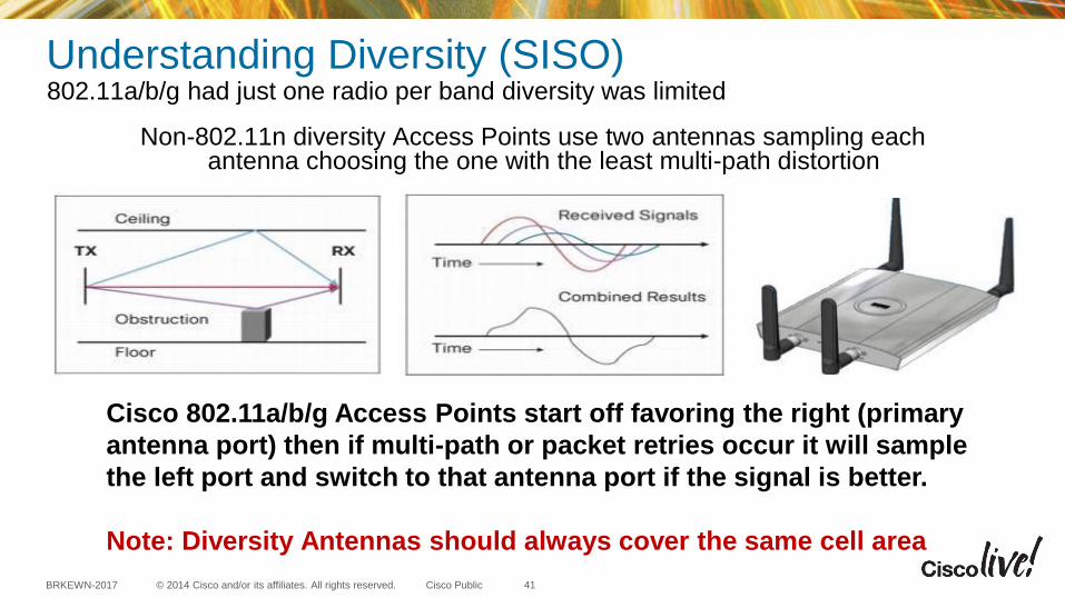
Understanding Diversity (SISO) 802.11a/b/g had just one radio per band diversity was limited
Non-802.11n diversity Access Points use two antennas sampling each antenna choosing the one with the least multi-path distortion
Cisco 802.11a/b/g Access Points start off favoring the right (primary
antenna port) then if multi-path or packet retries occur it will sample
the left port and switch to that antenna port if the signal is better.
Note: Diversity Antennas should always cover the same cell area
41
© 2014 Cisco and/or its affiliates. All rights reserved. BRKEWN-2017 Cisco Public
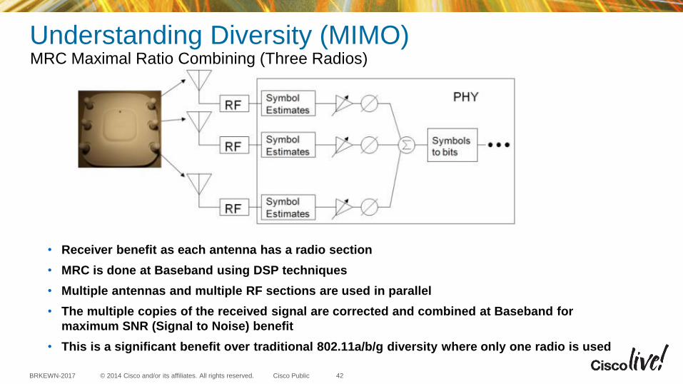
Understanding Diversity (MIMO) MRC Maximal Ratio Combining (Three Radios)
• Receiver benefit as each antenna has a radio section
• MRC is done at Baseband using DSP techniques
• Multiple antennas and multiple RF sections are used in parallel
• The multiple copies of the received signal are corrected and combined at Baseband for
maximum SNR (Signal to Noise) benefit
• This is a significant benefit over traditional 802.11a/b/g diversity where only one radio is used
42
© 2014 Cisco and/or its affiliates. All rights reserved. BRKEWN-2017 Cisco Public
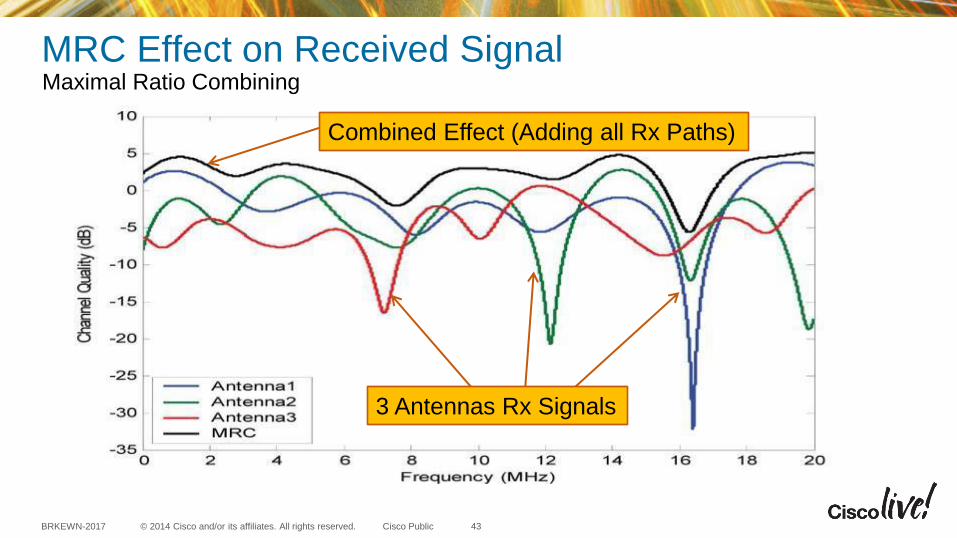
3 Antennas Rx Signals
Combined Effect (Adding all Rx Paths)
MRC Effect on Received Signal Maximal Ratio Combining
43
© 2014 Cisco and/or its affiliates. All rights reserved. BRKEWN-2017 Cisco Public
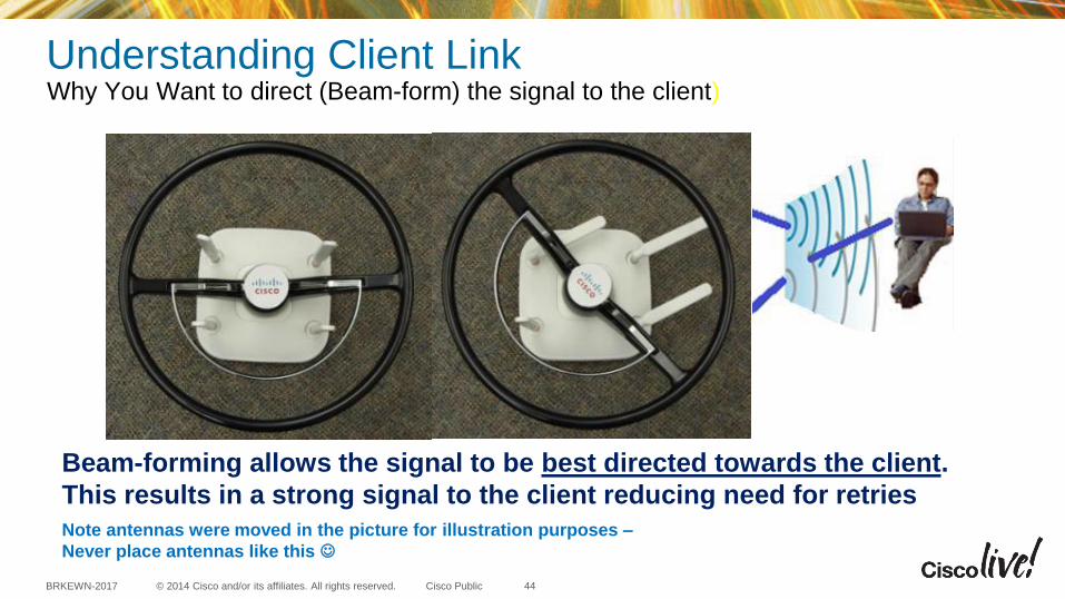
Beam-forming allows the signal to be best directed towards the client.
This results in a strong signal to the client reducing need for retries
Note antennas were moved in the picture for illustration purposes –
Never place antennas like this
Understanding Client Link Why You Want to direct (Beam-form) the signal to the client)
44
© 2014 Cisco and/or its affiliates. All rights reserved. BRKEWN-2017 Cisco Public
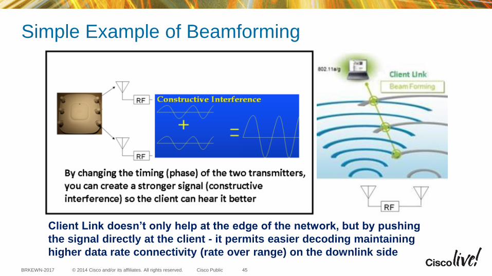
Client Link doesn’t only help at the edge of the network, but by pushing
the signal directly at the client - it permits easier decoding maintaining
higher data rate connectivity (rate over range) on the downlink side
Simple Example of Beamforming
45

© 2014 Cisco and/or its affiliates. All rights reserved. BRKEWN-2017 Cisco Public
Beamforming: ClientLink 1.0 first introduced in the AP-1140 helped OFDM and Single stream clients
The AP-1140/1260/3500
has dual band radio support
using single band antennas.
Each radio band (2.4 & 5 GHz)
has separate independent radios
Two transceivers (Tx/Rx) per
band
This two transceiver design
allows for beam-forming to
legacy clients 802.11a/g - this is
called Client Link.
AP1140, 1260 and 3500 can beamform to legacy
802.11a/g clients. This is called Client Link 1.0 and
supports up to 15 clients per radio
Note: Client Link 1 & 2 works on the DOWNLINK (AP
to CLIENT) so the client can better decode packets
46

© 2014 Cisco and/or its affiliates. All rights reserved. BRKEWN-2017 Cisco Public
2nd Generation Series AP’s with ClientLink 2.0 Client Link 2.0 is Client Link with Enhanced .11n Beam-forming
2600 & 3600 Series APs have
four transceivers per band
and all the antennas are used
in the Client Link 2.0 beam-
forming process
More radios, less antennas,
all 8 radios (4 per band) are
Transmit/Receive “Tx/Rx”
47
Cisco 2600 & 3600 Access Points fully support Cisco Client Link 2.0 (beam-forming)
to 802.11a/g/n clients as well as 802.11n clients @ 1, 2 & 3 Spatial Streams
Take away – CLIENT LINK 2.0 beam-forms to all clients today improving the overall
user experience and performance

© 2014 Cisco and/or its affiliates. All rights reserved. BRKEWN-2017 Cisco Public
Beam-forming Spatial Streams (ClientLink 3.0) All the features of ClientLink 2.0 + 3-ss 11ac Clients
Note: Only Cisco APs can beam-form a 3-SS signal as it
requires 4 transmitters - most APs on the market don’t
have this additional radio for reliability and performance
The additional radio assists in both transmit and receive.
The extra radio “D” is used
to augment spatial stream
data and is used in beam-
forming
Note .11n had support for
beam-forming but was never
adopted so there was no
TxBF without ClientLink
Client-Link performs beam-
forming on legacy 11a/g/n
clients as well as 802.11ac
clients 3-ss clients. 48
© 2014 Cisco and/or its affiliates. All rights reserved. BRKEWN-2017 Cisco Public
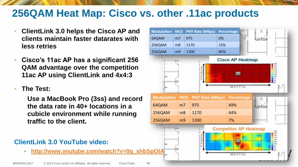
256QAM Heat Map: Cisco vs. other .11ac products
ClientLink 3.0 YouTube video:
http://www.youtube.com/watch?v=0q_shbSpOIA
• ClientLink 3.0 helps the Cisco AP and clients maintain faster datarates with less retries
• Cisco’s 11ac AP has a significant 256 QAM advantage over the competition 11ac AP using ClientLink and 4x4:3
• The Test:
Use a MacBook Pro (3ss) and record the data rate in 40+ locations in a cubicle environment while running traffic to the client.
Cisco AP Heatmap
Competitor AP Heatmap
49

Understanding 802.11n

© 2014 Cisco and/or its affiliates. All rights reserved. BRKEWN-2017 Cisco Public
Before .11n - Review of 802.11a and 802.11b/g
• Only 1 Transmitter & 1 Receiver (per band) – up to 54 Mbps
• Early non .11n diversity Access Points use two antennas with one radio per band sampling each antenna - choosing the one with the least multi-path distortion and then transmitting back on the same antenna
• Since speeds were only 54 Mbps 10/100 ports were fine
• Since PoE was 15.4W the radios had plenty of power the higher gain antennas above 6 dBi were permitted
• Both Indoor/Outdoor was permitted without frequency restrictions 802.11n introduced restrictions for outdoors creating the 3502P
51
NOTE: This is LEGACY technology so for best performance on
enterprise networks consider disabling .11b rates
© 2014 Cisco and/or its affiliates. All rights reserved. BRKEWN-2017 Cisco Public
Elements of 802.11n - Terminology • MIMO – Multiple Input Multiple Output when radio signals called “streams” are being
transmitted or received simultaneously
• MRC – Maximal Ratio Combining the ability to combine the received signals from multiple antennas (receivers) to reassemble and decode the spatial stream
• Spatial Stream – Transmitted signal - multiple transmitted signals called streams can carry redundant or different information on each transmitted stream.
• Spatial Multiplexing – ability to simultaneously send multiple streams of data and decode with multiple receivers to increase channel capacity (throughput).
• Packet Aggregation – combining packets into a single MAC layer frame to reduce overhead from packet headers for more efficiency
• Channel Bonding – Using more than one channel (combining them) for more bandwidth.
• TxBF – Transmit Beam-forming used in 802.11ac and in 802.11n with Cisco ClientLink
• 4x4:3 – Terminology for number of transmitters, receivers and spatial streams supported
52

© 2014 Cisco and/or its affiliates. All rights reserved. BRKEWN-2017 Cisco Public
MRC - Maximal Ratio Combining Receiving and processing the received signal from the client
Pre-802.11n Access Points had NO MRC and used only 1 radio per band sampling the 2 antennas picking the best one.
53
Access Points with MRC each antenna
has a dedicated receiver and combines
the signal received on all antennas to
best decode and process the
information with less retries.
© 2014 Cisco and/or its affiliates. All rights reserved. BRKEWN-2017 Cisco Public
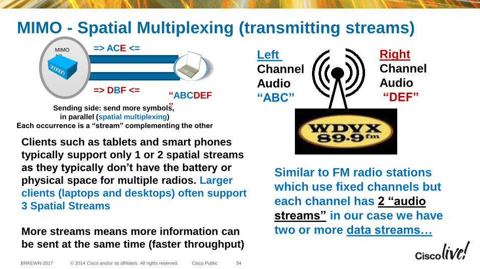
MIMO - Spatial Multiplexing (transmitting streams)
Clients such as tablets and smart phones
typically support only 1 or 2 spatial streams
as they typically don’t have the battery or
physical space for multiple radios. Larger
clients (laptops and desktops) often support
3 Spatial Streams
More streams means more information can
be sent at the same time (faster throughput)
“ABCDEF
”
=> DBF <=
=> ACE <= MIMO
AP
Sending side: send more symbols,
in parallel (spatial multiplexing)
Each occurrence is a “stream” complementing the other
Left
Channel
Audio
“ABC”
Right
Channel
Audio
“DEF”
Similar to FM radio stations
which use fixed channels but
each channel has 2 “audio
streams” in our case we have
two or more data streams…
54
© 2014 Cisco and/or its affiliates. All rights reserved. BRKEWN-2017 Cisco Public
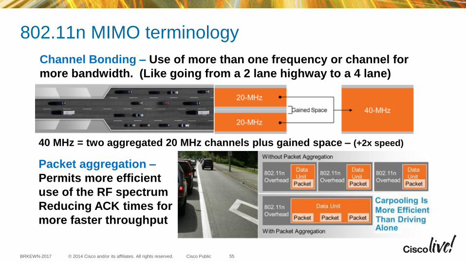
802.11n MIMO terminology
Channel Bonding – Use of more than one frequency or channel for
more bandwidth. (Like going from a 2 lane highway to a 4 lane)
40 MHz = two aggregated 20 MHz channels plus gained space – (+2x speed)
Packet aggregation –
Permits more efficient
use of the RF spectrum
Reducing ACK times for
more faster throughput
55

© 2014 Cisco and/or its affiliates. All rights reserved. BRKEWN-2017 Cisco Public
Channel Bonding – Subcarriers
When using the 40-MHz bonded channel, 802.11n takes advantage of the fact that each 20-MHz channel has a small
amount of the channel that is reserved at the top and bottom, to reduce interference in those adjacent channels.
When using 40-MHz channels, the top of the lower channel and the bottom of the upper channel don't have to be
reserved to avoid interference. These small parts of the channel can now be used to carry information. By using
the two 20-MHz channels more efficiently in this way, 802.11n achieves slightly more than doubling the data rate
when moving from 20-MHz to 40-MHz channels
802.11n can use both
20-MHz and 40-MHz
channels.
The 40-MHz channels in
802.11n are two adjacent
20-MHz channels,
bonded together.
56
© 2014 Cisco and/or its affiliates. All rights reserved. BRKEWN-2017 Cisco Public
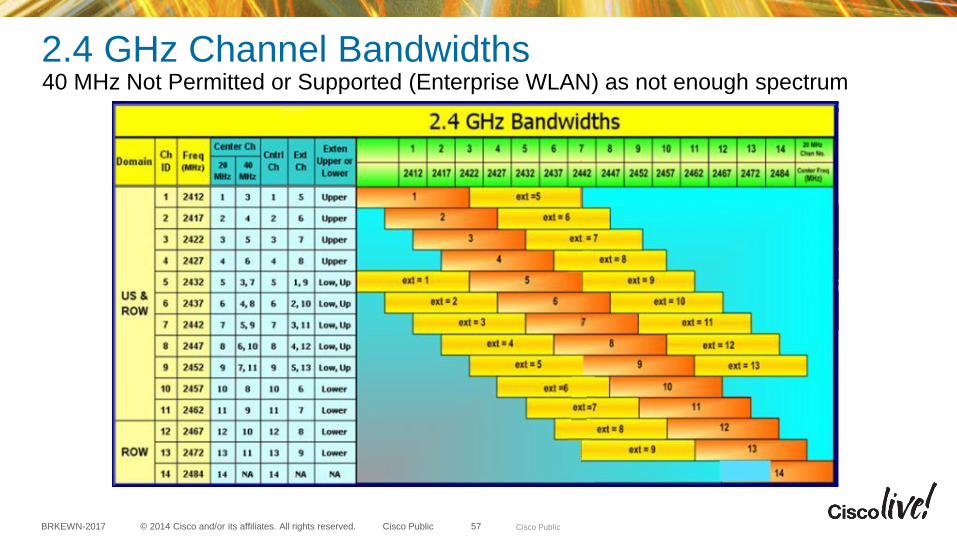
2.4 GHz Channel Bandwidths 40 MHz Not Permitted or Supported (Enterprise WLAN) as not enough spectrum
Cisco Public 57
© 2014 Cisco and/or its affiliates. All rights reserved. BRKEWN-2017 Cisco Public
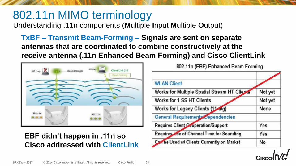
802.11n MIMO terminology Understanding .11n components (Multiple Input Multiple Output)
TxBF – Transmit Beam-Forming – Signals are sent on separate
antennas that are coordinated to combine constructively at the
receive antenna (.11n Enhanced Beam Forming) and Cisco ClientLink
EBF didn’t happen in .11n so
Cisco addressed with ClientLink
58
© 2014 Cisco and/or its affiliates. All rights reserved. BRKEWN-2017 Cisco Public
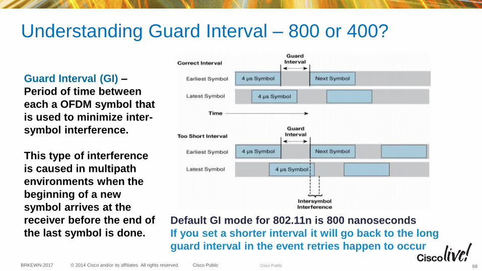
Understanding Guard Interval – 800 or 400?
Guard Interval (GI) –
Period of time between
each a OFDM symbol that
is used to minimize inter-
symbol interference.
This type of interference
is caused in multipath
environments when the
beginning of a new
symbol arrives at the
receiver before the end of
the last symbol is done.
Default GI mode for 802.11n is 800 nanoseconds
If you set a shorter interval it will go back to the long
guard interval in the event retries happen to occur
Cisco Public 59

© 2014 Cisco and/or its affiliates. All rights reserved. BRKEWN-2017 Cisco Public
Data Rates for 802.11n (speeds are based on channel width and streams)
AP-700,1040,1140,
1250,1260,1600 &
3500 can support
Up to 2-Streams
300 Mbps using
.11n rates
AP-2600,2700,
3600 & 3700
can support
Up to 3-Streams
450 Mbps using
.11n rates
60
© 2014 Cisco and/or its affiliates. All rights reserved. BRKEWN-2017 Cisco Public
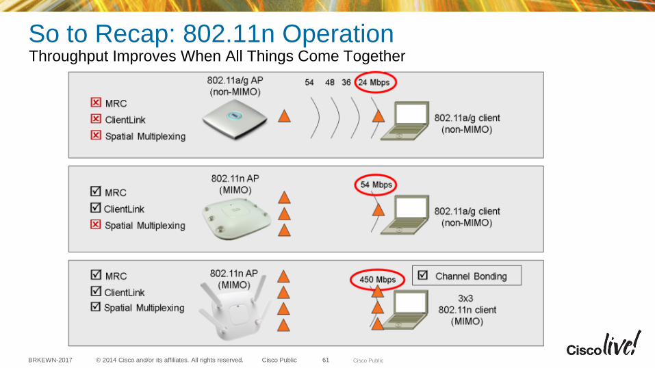
So to Recap: 802.11n Operation Throughput Improves When All Things Come Together
Cisco Public 61
Understanding 802.11ac Building upon the 802.11n foundation

© 2014 Cisco and/or its affiliates. All rights reserved. BRKEWN-2017 Cisco Public
Elements of Enterprise 802.11ac – Wave1 Here are the key features of 802.11ac (Wave-1)
• Support for faster modulation 256-QAM
• Ability to use 1, 2 & 3 Spatial Streams
• Extended bandwidth now up to 80 MHz
• Beam-forming standard (for .11ac clients)
• Enhanced methods of bandwidth sharing
Wi-Fi Alliance certifies 802.11ac products for interoperability
@ 20/40/80 MHz, using 256-QAM and 1, 2 and 3 Spatial Streams
Note: Wave-2 is still in development, so nothing is ready today.
Proposed 160 MHz bonding, Multi-User MIMO, additional streams.
63

© 2014 Cisco and/or its affiliates. All rights reserved. BRKEWN-2017 Cisco Public
General thoughts – Why do I need 802.11ac? Because it builds on 802.11n foundation adding faster throughput and performance
• Need for more throughput – smart phones and tablets usually have only 1 radio
• Channel Bonding and more complex modulation (256-QAM) does more with only 1 radio
• Logical progression for significant performance from earlier technologies
• 11b (11 Mbps), 11a/g (54 Mbps), 11n (600 Mbps), 11ac (1300 Mbps), <Wave-1>
• Beam-forming is now implemented in 11ac clients but ClientLink still used for 11n clients
802.11ac clients are emerging with
laptops and tablets supporting 3
Spatial Streams and even smart
phones supporting 1 & 2 spatial
streams @ 80 MHz
64

© 2014 Cisco and/or its affiliates. All rights reserved. BRKEWN-2017 Cisco Public
Understanding Channel Bonding 802.11ac introduced 80 MHz
One method to gain significant
throughput (2x or more) is to bond
the channels using more bandwidth.
This helps 1, 2 and 3-SS clients.
Single spatial stream clients also
realize physical size and battery life
benefits.
Bonding
actually blends
the channels
together so
you gain a
small amount
of extra
spectrum for
data use
65
© 2014 Cisco and/or its affiliates. All rights reserved. BRKEWN-2017 Cisco Public
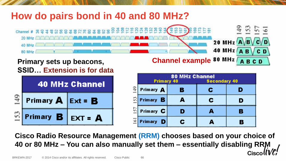
How do pairs bond in 40 and 80 MHz?
Channel example
Cisco Radio Resource Management (RRM) chooses based on your choice of
40 or 80 MHz – You can also manually set them – essentially disabling RRM
Primary sets up beacons,
SSID… Extension is for data
66
© 2014 Cisco and/or its affiliates. All rights reserved. BRKEWN-2017 Cisco Public
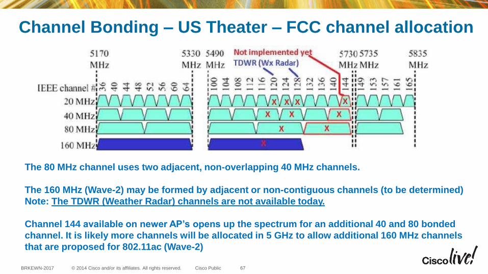
Channel Bonding – US Theater – FCC channel allocation
The 80 MHz channel uses two adjacent, non-overlapping 40 MHz channels.
The 160 MHz (Wave-2) may be formed by adjacent or non-contiguous channels (to be determined)
Note: The TDWR (Weather Radar) channels are not available today.
Channel 144 available on newer AP’s opens up the spectrum for an additional 40 and 80 bonded
channel. It is likely more channels will be allocated in 5 GHz to allow additional 160 MHz channels
that are proposed for 802.11ac (Wave-2)
67

© 2014 Cisco and/or its affiliates. All rights reserved. BRKEWN-2017 Cisco Public
Channel Bonding – Possible US expansion (proposed)
• In the US there are currently 22/10/5/1 channels with bandwidth 20/40/80/160MHz channels
• With the proposed opening up of 5.35-5.47GHz & 5.85-5.925GHz, spectrum, the number of
channels increases to 34/16/8/3
• If the industry manages to take back the TDWR channels, the number of increases to
37/18/9/4
68

© 2014 Cisco and/or its affiliates. All rights reserved. BRKEWN-2017 Cisco Public
Why is channel bonding & 256-QAM so important?
More than 1-SS requires
the client have more
radios which draws more
power from the battery.
Most smart phones and
some tablets will use 1-SS
More powerful tablets &
laptops use 2 & 3-SS
The goal is to save
physical size and battery
life yet increase
throughput
How else can you get to
433 Mbps with one radio?
Newer phones
such as the HTC
One & Samsung
S4 have support
for 802.11ac
69
© 2014 Cisco and/or its affiliates. All rights reserved. BRKEWN-2017 Cisco Public
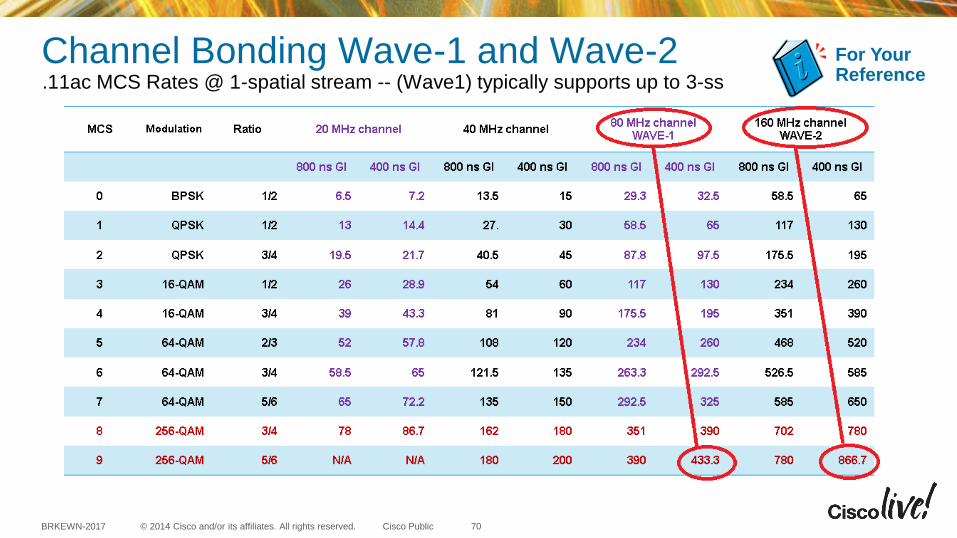
Channel Bonding Wave-1 and Wave-2 .11ac MCS Rates @ 1-spatial stream -- (Wave1) typically supports up to 3-ss
For Your Reference
70
© 2014 Cisco and/or its affiliates. All rights reserved. BRKEWN-2017 Cisco Public
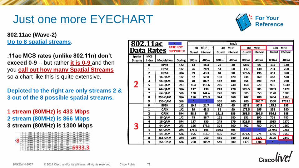
Just one more EYECHART 802.11ac (Wave-2)
Up to 8 spatial streams.
.11ac MCS rates (unlike 802.11n) don’t
exceed 0-9 -- but rather it is 0-9 and then
you call out how many Spatial Streams
so a chart like this is quite extensive.
Depicted to the right are only streams 2 &
3 out of the 8 possible spatial streams.
1 stream (80MHz) is 433 Mbps
2 stream (80MHz) is 866 Mbps
3 stream (80MHz) is 1300 Mbps
For Your Reference
71

© 2014 Cisco and/or its affiliates. All rights reserved. BRKEWN-2017 Cisco Public
Streams and channel bonding 11ac @ 80MHz
1 stream (80MHz) is 433 Mbps
2 stream (80MHz) is 866 Mbps
3 stream (80MHz) is 1300 Mbps
802.11ac Performance Table
What’s the real expected throughput?*
Smartphones from 210 Mbps*
Tablets from 460 Mbps*
High End Laptops from +680 Mbps*
* Assumes 70% MAC
efficiency and half duplex
Note: This is why GigE is fine for
802.11ac (Wave-1)
72
© 2014 Cisco and/or its affiliates. All rights reserved. BRKEWN-2017 Cisco Public
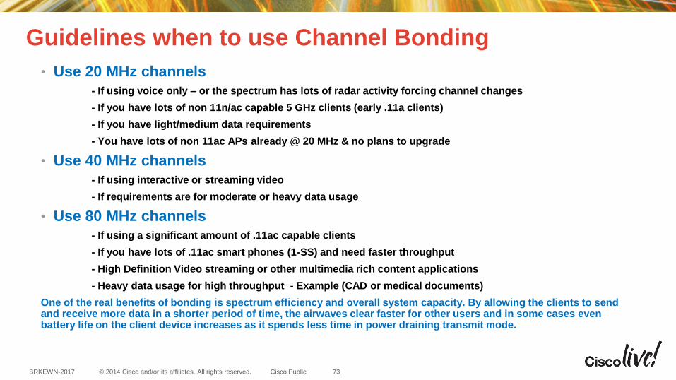
Guidelines when to use Channel Bonding
• Use 20 MHz channels
- If using voice only – or the spectrum has lots of radar activity forcing channel changes
- If you have lots of non 11n/ac capable 5 GHz clients (early .11a clients)
- If you have light/medium data requirements
- You have lots of non 11ac APs already @ 20 MHz & no plans to upgrade
• Use 40 MHz channels
- If using interactive or streaming video
- If requirements are for moderate or heavy data usage
• Use 80 MHz channels
- If using a significant amount of .11ac capable clients
- If you have lots of .11ac smart phones (1-SS) and need faster throughput
- High Definition Video streaming or other multimedia rich content applications
- Heavy data usage for high throughput - Example (CAD or medical documents)
One of the real benefits of bonding is spectrum efficiency and overall system capacity. By allowing the clients to send and receive more data in a shorter period of time, the airwaves clear faster for other users and in some cases even battery life on the client device increases as it spends less time in power draining transmit mode.
73
© 2014 Cisco and/or its affiliates. All rights reserved. BRKEWN-2017 Cisco Public
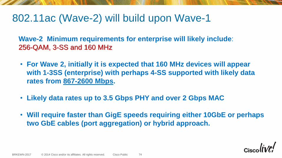
802.11ac (Wave-2) will build upon Wave-1
Wave-2 Minimum requirements for enterprise will likely include:
256-QAM, 3-SS and 160 MHz
• For Wave 2, initially it is expected that 160 MHz devices will appear
with 1-3SS (enterprise) with perhaps 4-SS supported with likely data
rates from 867-2600 Mbps.
• Likely data rates up to 3.5 Gbps PHY and over 2 Gbps MAC
• Will require faster than GigE speeds requiring either 10GbE or perhaps
two GbE cables (port aggregation) or hybrid approach.
74

© 2014 Cisco and/or its affiliates. All rights reserved. BRKEWN-2017 Cisco Public
Physical Layer – Type and number of cables?
A single GbE cable is fine for (Wave-1)
Multiple clients (all connecting at different speeds) will not exceed GbE. Wave-2 could exceed GbE speeds as it has support for additional spatial streams and up to 160 MHz of bandwidth so for now, it is recommended for new installs where there is a requirement to support 11ac Wave-2 that you pull two CAT6a cables at least until this standard is better defined.
A pair of CAT6a cables allows you to fall back to using 2 GbE ports for some iterations of (Wave-2) if required. Additionally, if the second cable isn’t needed it can be used to bring the console port back.
CAT5e cables may be used as the 2nd cable pull for cost savings but at least 1 cable should be CAT6a as CAT5 does not support 10GbE.
75

Current Access Point Products and choosing the correct AP (internal or external) antennas?
© 2014 Cisco and/or its affiliates. All rights reserved. BRKEWN-2017 Cisco Public
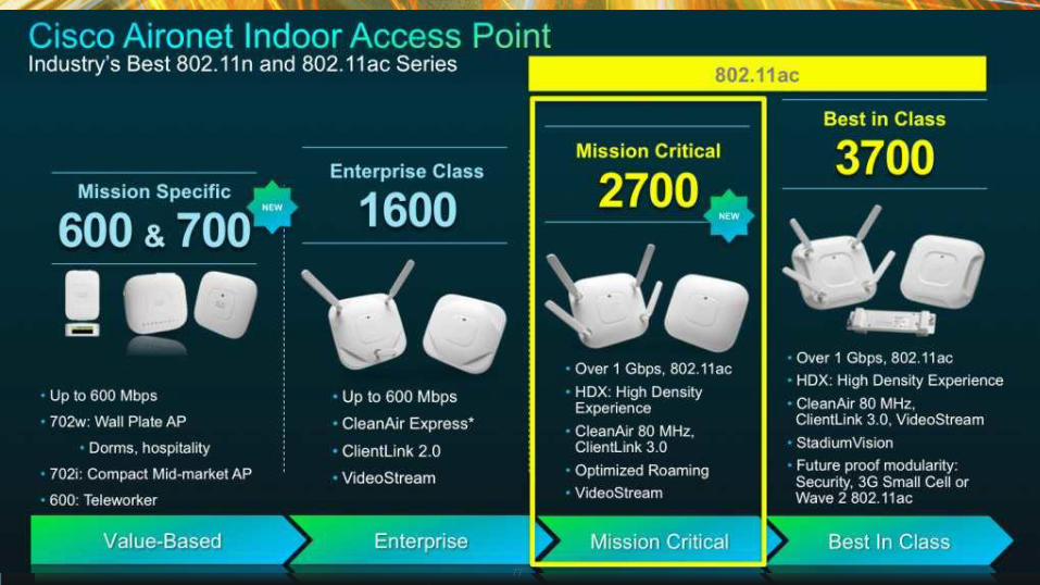
Cisco Aironet Indoor Access Point Industry’s Best 802.11n and 802.11ac Series
Mission Specific
600 & 700
Enterprise Class
1600
Mission Critical
2600
Best in Class
3700
Enterprise Best In Class Value-Based Mission Critical
• Up to 600 Mbps
• 702w: Wall Plate AP
• Dorms, hospitality
• 702i: Compact Mid-market AP
• 600: Teleworker
• Up to 600 Mbps
• CleanAir Express*
• ClientLink 2.0
• VideoStream
• Up to 900 Mbps
• High Client Scalability
• CleanAir
• ClientLink 2.0
• VideoStream
• Over 1 Gbps, 802.11ac support
• High Density Experience
• CleanAir 80 MHz, ClientLink 3.0, VideoStream
• Future proof modularity: Security, 3G Small Cell or Wave 2 802.11ac
NEW
NEW
77

© 2014 Cisco and/or its affiliates. All rights reserved. BRKEWN-2017 Cisco Public
Identifying Access Points (Physically)
AP-2700
3x4:3 AP-2600
3x4:3
AP-3600
4x4:3
AP-3700
4x4:3
All the Access Points have a slightly different look so you can tell
them apart visually – 3600 & 3700 support modular upgrades
78
© 2014 Cisco and/or its affiliates. All rights reserved. BRKEWN-2017 Cisco Public
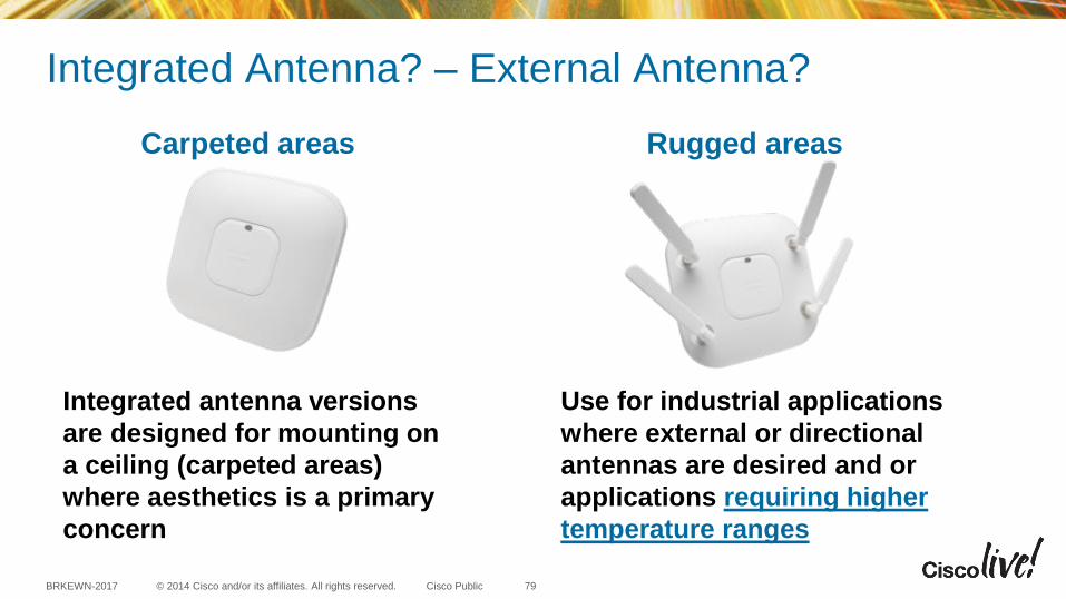
Integrated Antenna? – External Antenna?
Integrated antenna versions
are designed for mounting on
a ceiling (carpeted areas)
where aesthetics is a primary
concern
Use for industrial applications
where external or directional
antennas are desired and or
applications requiring higher
temperature ranges
Carpeted areas Rugged areas
79
© 2014 Cisco and/or its affiliates. All rights reserved. BRKEWN-2017 Cisco Public
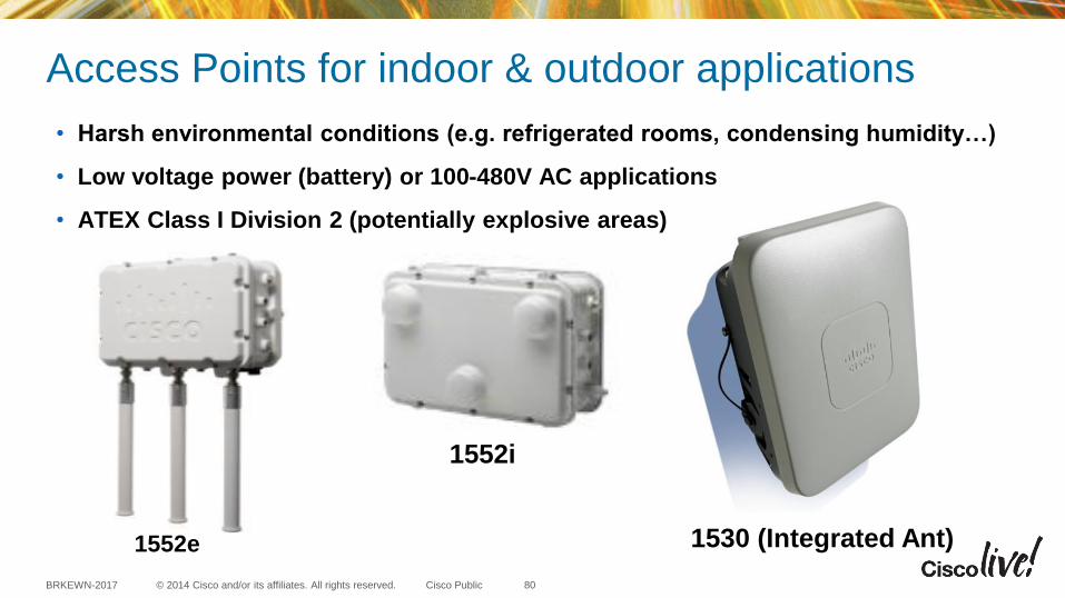
Access Points for indoor & outdoor applications
• Harsh environmental conditions (e.g. refrigerated rooms, condensing humidity…)
• Low voltage power (battery) or 100-480V AC applications
• ATEX Class I Division 2 (potentially explosive areas)
1530 (Integrated Ant) 1552e
80
1552i

Installation and Deployment Considerations

© 2014 Cisco and/or its affiliates. All rights reserved. BRKEWN-2017 Cisco Public
Site Survey
82
Also see Cisco Access Point Deployment guide at this URL http://www.cisco.com/c/en/us/td/docs/wireless/technology/apdeploy/7-6/Cisco_Aironet_3700AP.html
© 2014 Cisco and/or its affiliates. All rights reserved. BRKEWN-2017 Cisco Public
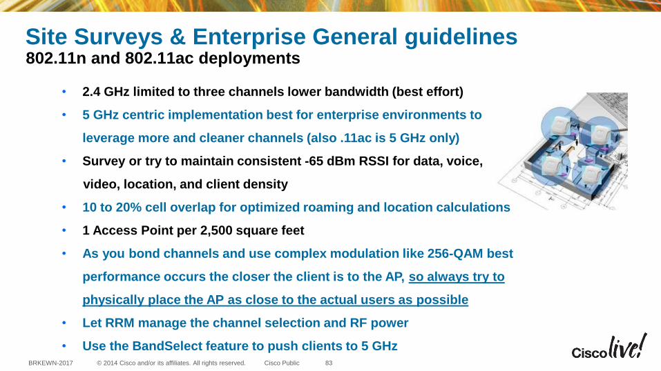
Site Surveys & Enterprise General guidelines 802.11n and 802.11ac deployments
• 2.4 GHz limited to three channels lower bandwidth (best effort)
• 5 GHz centric implementation best for enterprise environments to
leverage more and cleaner channels (also .11ac is 5 GHz only)
• Survey or try to maintain consistent -65 dBm RSSI for data, voice,
video, location, and client density
• 10 to 20% cell overlap for optimized roaming and location calculations
• 1 Access Point per 2,500 square feet
• As you bond channels and use complex modulation like 256-QAM best
performance occurs the closer the client is to the AP, so always try to
physically place the AP as close to the actual users as possible
• Let RRM manage the channel selection and RF power
• Use the BandSelect feature to push clients to 5 GHz 83
© 2014 Cisco and/or its affiliates. All rights reserved. BRKEWN-2017 Cisco Public
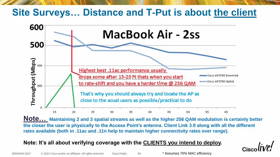
Site Surveys… Distance and T-Put is about the client
* Assumes 70% MAC efficiency
Note… Maintaining 2 and 3 spatial streams as well as the higher 256 QAM modulation is certainly better
the closer the user is physically to the Access Point’s antenna. Client Link 3.0 along with all the different
rates available (both in .11ac and .11n help to maintain higher connectivity rates over range).
Note: It’s all about verifying coverage with the CLIENTS you intend to deploy.
84

© 2014 Cisco and/or its affiliates. All rights reserved. BRKEWN-2017 Cisco Public
Upgrading Access Points 1:1 or another survey?
Question: If I replace my Access Points with a newer 802.11ac Access Point do I have to
resurvey? Is the spacing the same between 11n and 11ac?
Answer: 11ac builds upon 11n, and cell sizes are similar. Years ago the guidelines were
1 per 5,000 Sq Feet for data only and 1 per 3,000 sq. feet for voice & location.
We now recommend 1 per 2,500 sq feet and no longer break it down by applications.
Access Points have always had
similar heat maps – There will
always be slight differences but
the goal is to maintain uniform
coverage with less retries
It is always a good idea to check
and verify coverage.
85
© 2014 Cisco and/or its affiliates. All rights reserved. BRKEWN-2017 Cisco Public
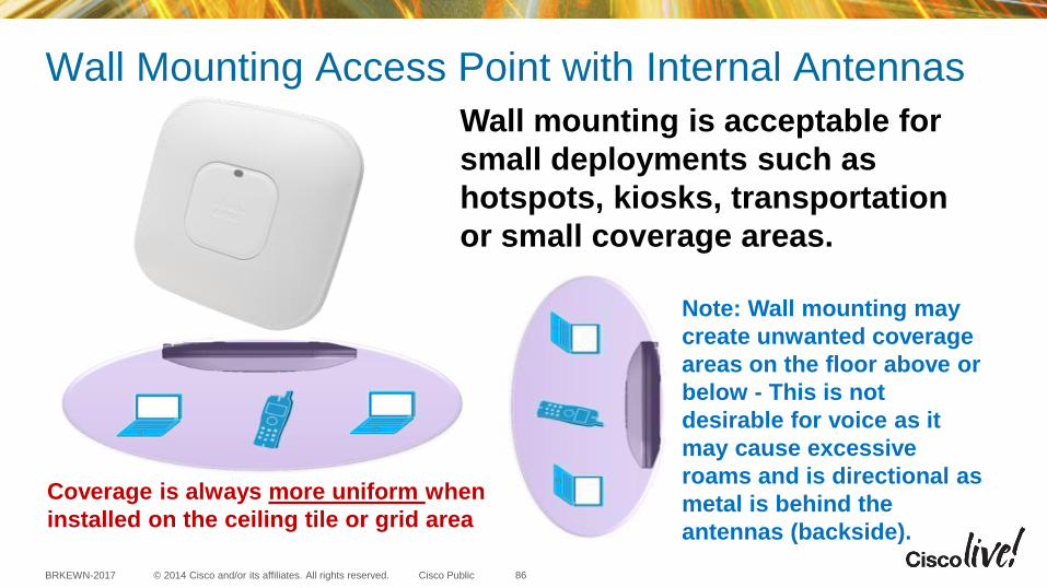
Wall Mounting Access Point with Internal Antennas
Coverage is always more uniform when
installed on the ceiling tile or grid area
Note: Wall mounting may
create unwanted coverage
areas on the floor above or
below - This is not
desirable for voice as it
may cause excessive
roams and is directional as
metal is behind the
antennas (backside).
Wall mounting is acceptable for
small deployments such as
hotspots, kiosks, transportation
or small coverage areas.
86
© 2014 Cisco and/or its affiliates. All rights reserved. BRKEWN-2017 Cisco Public
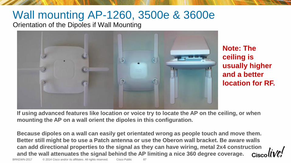
Wall mounting AP-1260, 3500e & 3600e Orientation of the Dipoles if Wall Mounting
If using advanced features like location or voice try to locate the AP on the ceiling, or when
mounting the AP on a wall orient the dipoles in this configuration.
Because dipoles on a wall can easily get orientated wrong as people touch and move them.
Better still might be to use a Patch antenna or use the Oberon wall bracket. Be aware walls
can add directional properties to the signal as they can have wiring, metal 2x4 construction
and the wall attenuates the signal behind the AP limiting a nice 360 degree coverage.
Note: The
ceiling is
usually higher
and a better
location for RF.
87
© 2014 Cisco and/or its affiliates. All rights reserved. BRKEWN-2017 Cisco Public
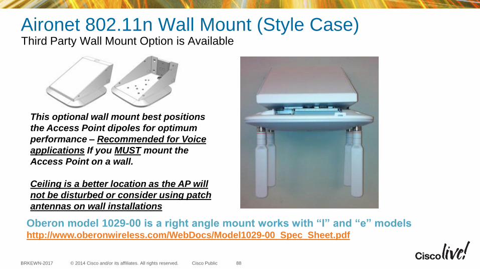
Aironet 802.11n Wall Mount (Style Case) Third Party Wall Mount Option is Available
Oberon model 1029-00 is a right angle mount works with “I” and “e” models http://www.oberonwireless.com/WebDocs/Model1029-00_Spec_Sheet.pdf
This optional wall mount best positions
the Access Point dipoles for optimum
performance – Recommended for Voice
applications If you MUST mount the
Access Point on a wall.
Ceiling is a better location as the AP will
not be disturbed or consider using patch
antennas on wall installations
88
© 2014 Cisco and/or its affiliates. All rights reserved. BRKEWN-2017 Cisco Public
What About Mounting Options? Different Mounting Options for Ceiling APs
Cisco has options to mount to most
ceiling rails and directly into the tile for a
more elegant look
Locking enclosures and different color
plastic “skins” available from third party
sources such as
www.oberonwireless.com
www.terrawave.com 89
© 2014 Cisco and/or its affiliates. All rights reserved. BRKEWN-2017 Cisco Public
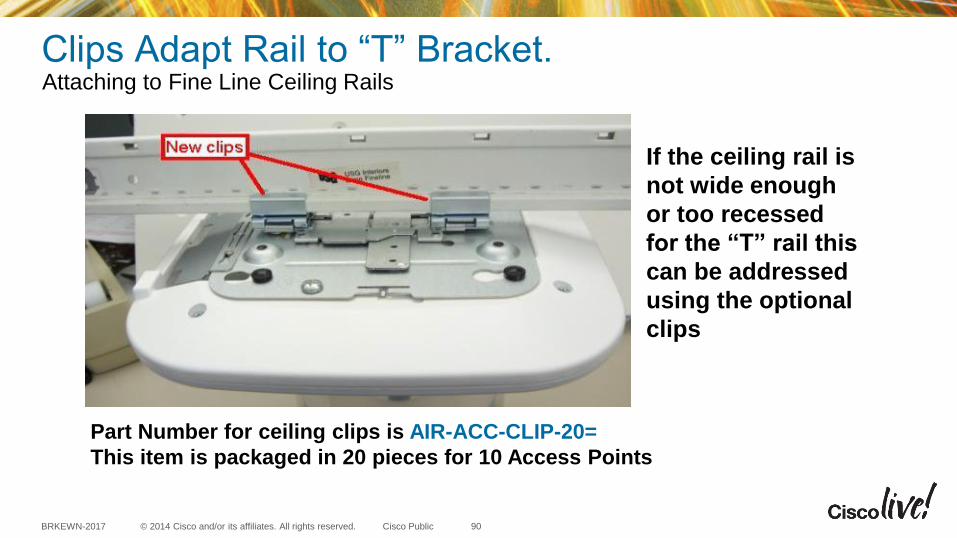
Clips Adapt Rail to “T” Bracket. Attaching to Fine Line Ceiling Rails
If the ceiling rail is
not wide enough
or too recessed
for the “T” rail this
can be addressed
using the optional
clips
Part Number for ceiling clips is AIR-ACC-CLIP-20=
This item is packaged in 20 pieces for 10 Access Points
90

© 2014 Cisco and/or its affiliates. All rights reserved. BRKEWN-2017 Cisco Public
Installation above the Ceiling Tiles An Optional Rail Above the Tiles May Be Used
Note: The AP should be as close to the tile as practical
AP bracket supports this optional T-bar box hanger item 2
(not supplied) Such as the Erico Caddy 512 or B-Line BA12
91
© 2014 Cisco and/or its affiliates. All rights reserved. BRKEWN-2017 Cisco Public
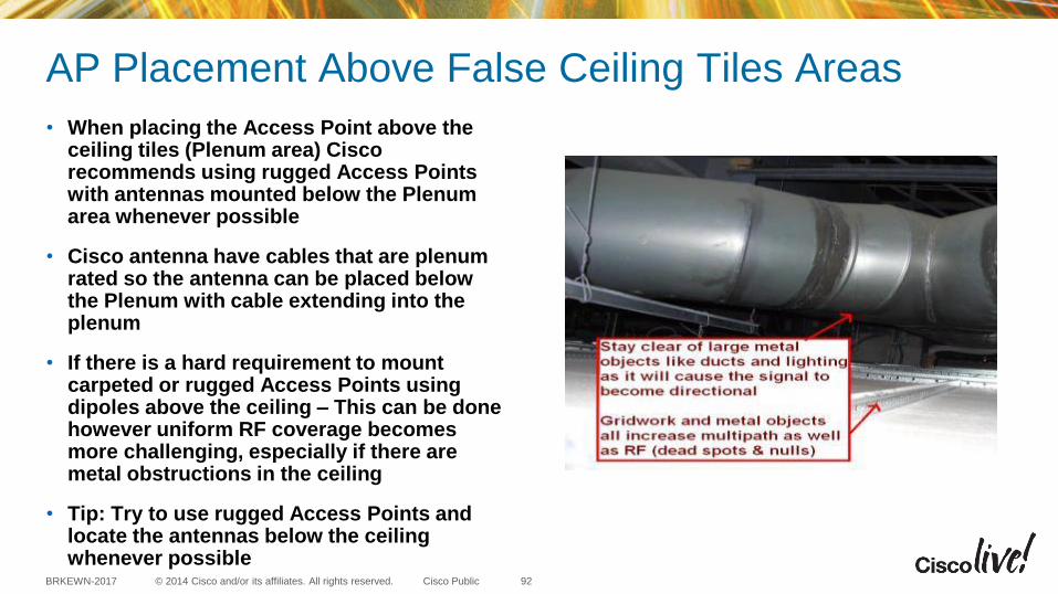
AP Placement Above False Ceiling Tiles Areas
• When placing the Access Point above the ceiling tiles (Plenum area) Cisco recommends using rugged Access Points with antennas mounted below the Plenum area whenever possible
• Cisco antenna have cables that are plenum rated so the antenna can be placed below the Plenum with cable extending into the plenum
• If there is a hard requirement to mount carpeted or rugged Access Points using dipoles above the ceiling – This can be done however uniform RF coverage becomes more challenging, especially if there are metal obstructions in the ceiling
• Tip: Try to use rugged Access Points and locate the antennas below the ceiling whenever possible
92
© 2014 Cisco and/or its affiliates. All rights reserved. BRKEWN-2017 Cisco Public
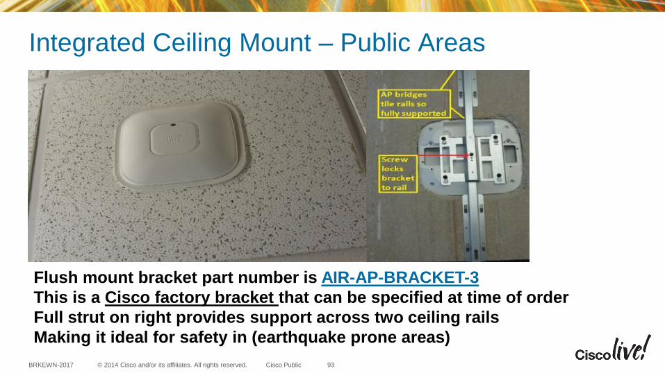
Integrated Ceiling Mount – Public Areas
Flush mount bracket part number is AIR-AP-BRACKET-3
This is a Cisco factory bracket that can be specified at time of order
Full strut on right provides support across two ceiling rails
Making it ideal for safety in (earthquake prone areas)
93
© 2014 Cisco and/or its affiliates. All rights reserved. BRKEWN-2017 Cisco Public
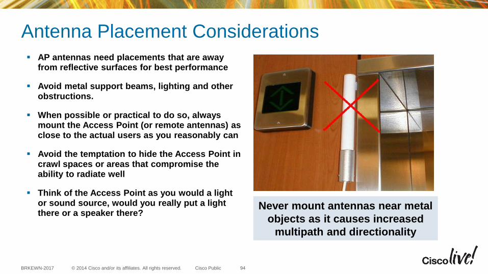
Antenna Placement Considerations
Never mount antennas near metal
objects as it causes increased
multipath and directionality
AP antennas need placements that are away from reflective surfaces for best performance
Avoid metal support beams, lighting and other obstructions.
When possible or practical to do so, always mount the Access Point (or remote antennas) as close to the actual users as you reasonably can
Avoid the temptation to hide the Access Point in crawl spaces or areas that compromise the ability to radiate well
Think of the Access Point as you would a light or sound source, would you really put a light there or a speaker there?
94
© 2014 Cisco and/or its affiliates. All rights reserved. BRKEWN-2017 Cisco Public
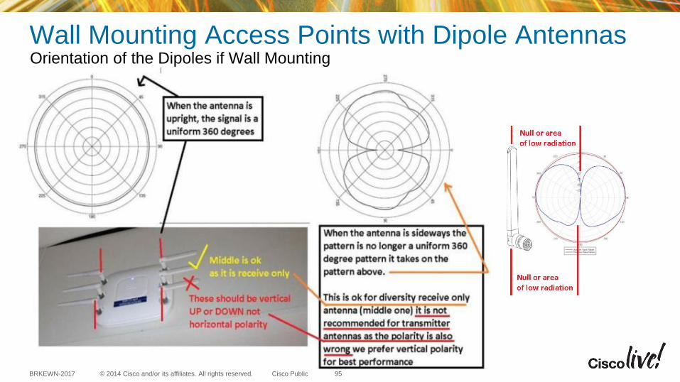
Wall Mounting Access Points with Dipole Antennas Orientation of the Dipoles if Wall Mounting
95

© 2014 Cisco and/or its affiliates. All rights reserved. BRKEWN-2017 Cisco Public
Wall Mounting AP-1260e, 3500e & 3600e Orientation of the Dipoles if Wall Mounting
Dipoles pointing UP or Down
are in vertical polarity
This is ideal for uniform
coverage.
Dipoles pointing sideways
are in horizontal polarity
Note: Cisco recommends transmitting
antennas use vertical polarity
96
A look at some installations that went wrong
© 2014 Cisco and/or its affiliates. All rights reserved. BRKEWN-2017 Cisco Public
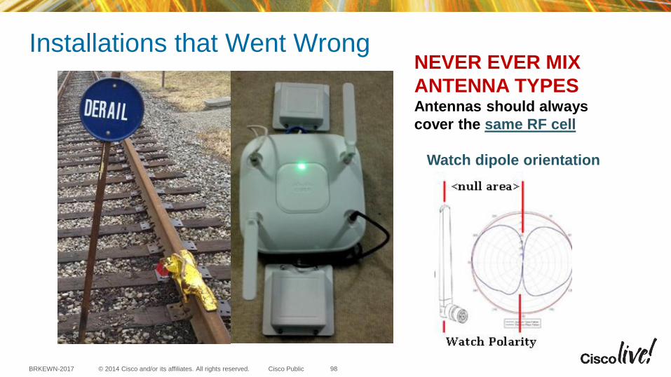
NEVER EVER MIX
ANTENNA TYPES Antennas should always
cover the same RF cell
Watch dipole orientation
Installations that Went Wrong
98

© 2014 Cisco and/or its affiliates. All rights reserved. BRKEWN-2017 Cisco Public
Mount the box horizontal and
extend the antennas down and not
right up against the metal enclosure
Patch antenna shooting across a metal fence
Multipath distortion causing severe retries
Installations that Went Wrong
99

© 2014 Cisco and/or its affiliates. All rights reserved. BRKEWN-2017 Cisco Public
When a dipole is mounted against
a metal object you lose all Omni-
directional properties.
It is now essentially a directional
patch suffering from acute
multipath distortion problems.
Add to that the metal pipes and it
is a wonder it works at all
Dipole antennas up against a metal box and large
metal pipes. This creates unwanted directionality
and multipath distortion – This also creates nulls
(dead areas) and creates packet retries
Tip: Access Points like light
sources should be in the clear
and near the users
Above ceiling installs that went wrong Yes it Happens and When it Does it is Expensive to Fix and No One is Happy
100
© 2014 Cisco and/or its affiliates. All rights reserved. BRKEWN-2017 Cisco Public
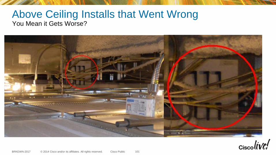
Above Ceiling Installs that Went Wrong You Mean it Gets Worse?
101

© 2014 Cisco and/or its affiliates. All rights reserved. BRKEWN-2017 Cisco Public
Ceiling mount AP mounted on the wall up
against metal pipe (poor coverage)
Outdoor NEMA box not weatherized
(just keeping the packets on ice)
Other Installations that Went Wrong
102
© 2014 Cisco and/or its affiliates. All rights reserved. BRKEWN-2017 Cisco Public
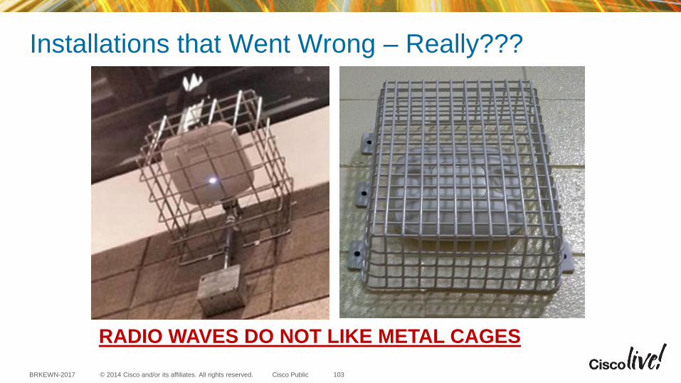
RADIO WAVES DO NOT LIKE METAL CAGES
Installations that Went Wrong – Really???
103
© 2014 Cisco and/or its affiliates. All rights reserved. BRKEWN-2017 Cisco Public
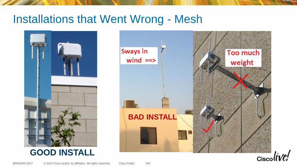
GOOD INSTALL
Installations that Went Wrong - Mesh
104
BAD INSTALL
© 2014 Cisco and/or its affiliates. All rights reserved. BRKEWN-2017 Cisco Public
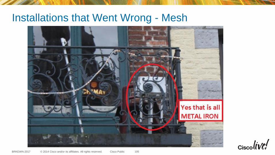
Installations that Went Wrong - Mesh
105

© 2014 Cisco and/or its affiliates. All rights reserved. BRKEWN-2017 Cisco Public
Building aesthetics matters – Antennas obstructed
Installations that Went Wrong - Mesh
106
© 2014 Cisco and/or its affiliates. All rights reserved. BRKEWN-2017 Cisco Public
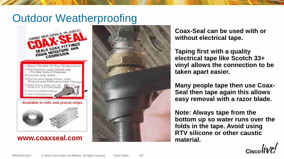
Outdoor Weatherproofing Coax-Seal can be used with or without electrical tape. Taping first with a quality electrical tape like Scotch 33+ vinyl allows the connection to be taken apart easier. Many people tape then use Coax-Seal then tape again this allows easy removal with a razor blade. Note: Always tape from the bottom up so water runs over the folds in the tape. Avoid using RTV silicone or other caustic material. www.coaxseal.com
107
© 2014 Cisco and/or its affiliates. All rights reserved. BRKEWN-2017 Cisco Public
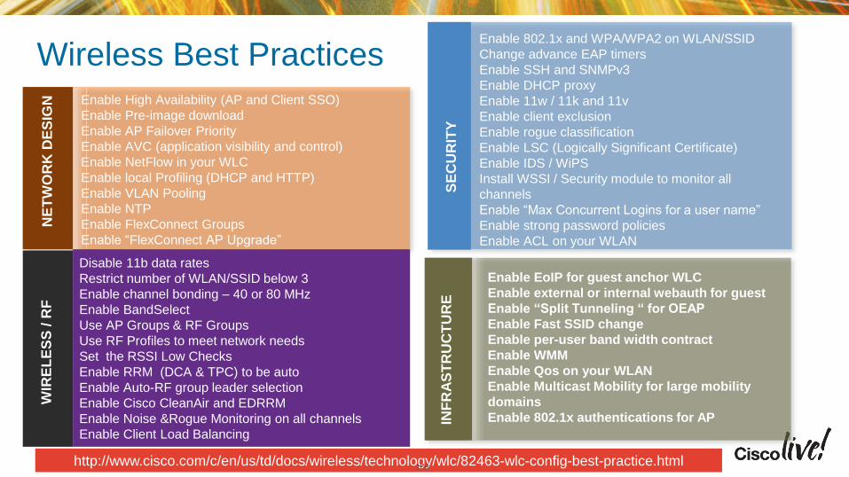
Wireless Best Practices N
ET
WO
RK
DE
SIG
N
Enable High Availability (AP and Client SSO)
Enable Pre-image download
Enable AP Failover Priority
Enable AVC (application visibility and control)
Enable NetFlow in your WLC
Enable local Profiling (DHCP and HTTP)
Enable VLAN Pooling
Enable NTP
Enable FlexConnect Groups
Enable “FlexConnect AP Upgrade”
Enable 802.1x and WPA/WPA2 on WLAN/SSID
Change advance EAP timers
Enable SSH and SNMPv3
Enable DHCP proxy
Enable 11w / 11k and 11v
Enable client exclusion
Enable rogue classification
Enable LSC (Logically Significant Certificate)
Enable IDS / WiPS
Install WSSI / Security module to monitor all
channels
Enable “Max Concurrent Logins for a user name”
Enable strong password policies
Enable ACL on your WLAN
INF
RA
ST
RU
CT
UR
E
Enable EoIP for guest anchor WLC
Enable external or internal webauth for guest
Enable “Split Tunneling “ for OEAP
Enable Fast SSID change
Enable per-user band width contract
Enable WMM
Enable Qos on your WLAN
Enable Multicast Mobility for large mobility
domains
Enable 802.1x authentications for AP
WIR
EL
ES
S / R
F
http://www.cisco.com/c/en/us/td/docs/wireless/technology/wlc/82463-wlc-config-best-practice.html S
EC
UR
ITY
Disable 11b data rates
Restrict number of WLAN/SSID below 3
Enable channel bonding – 40 or 80 MHz
Enable BandSelect
Use AP Groups & RF Groups
Use RF Profiles to meet network needs
Set the RSSI Low Checks
Enable RRM (DCA & TPC) to be auto
Enable Auto-RF group leader selection
Enable Cisco CleanAir and EDRRM
Enable Noise &Rogue Monitoring on all channels
Enable Client Load Balancing
108

© 2014 Cisco and/or its affiliates. All rights reserved. BRKEWN-2017 Cisco Public
Summary
“RF Matters”
109
© 2014 Cisco and/or its affiliates. All rights reserved. BRKEWN-2017 Cisco Public
Recommended Reading
“RF Matters” Also see the Cisco AP deployment guide at this URL http://www.cisco.com/c/en/us/td/docs/wireless/technology/apdeploy/7-6/Cisco_Aironet_3700AP.html
110

© 2014 Cisco and/or its affiliates. All rights reserved. BRKEWN-2017 Cisco Public
Continue Your Education
• Demos in the Cisco Campus
• Walk-in Self-Paced Labs
• Table Topics
• Meet the Engineer 1:1 meetings
111


Backup Slides… time permitting

© 2014 Cisco and/or its affiliates. All rights reserved. BRKEWN-2017 Cisco Public
The Richfield Ohio (Aironet) Facility A Quick Peek Where Antennas Are Designed...
115
© 2014 Cisco and/or its affiliates. All rights reserved. BRKEWN-2017 Cisco Public
The Richfield Ohio (Aironet) Facility Qualifying Cisco and 3rd Party Antennas
Satimo software compatible with
Stargate-64 System. Basic
measurement tool is 8753ES
Network Analyzer.
Cisco Anechoic chamber using an 45 cm
absorber all the way, around 1-6 GHz
Anechoic means “without echo”
116
© 2014 Cisco and/or its affiliates. All rights reserved. BRKEWN-2017 Cisco Public
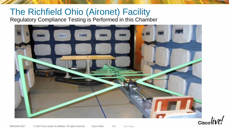
The Richfield Ohio (Aironet) Facility Regulatory Compliance Testing is Performed in this Chamber
Cisco Public 117
© 2014 Cisco and/or its affiliates. All rights reserved. BRKEWN-2017 Cisco Public
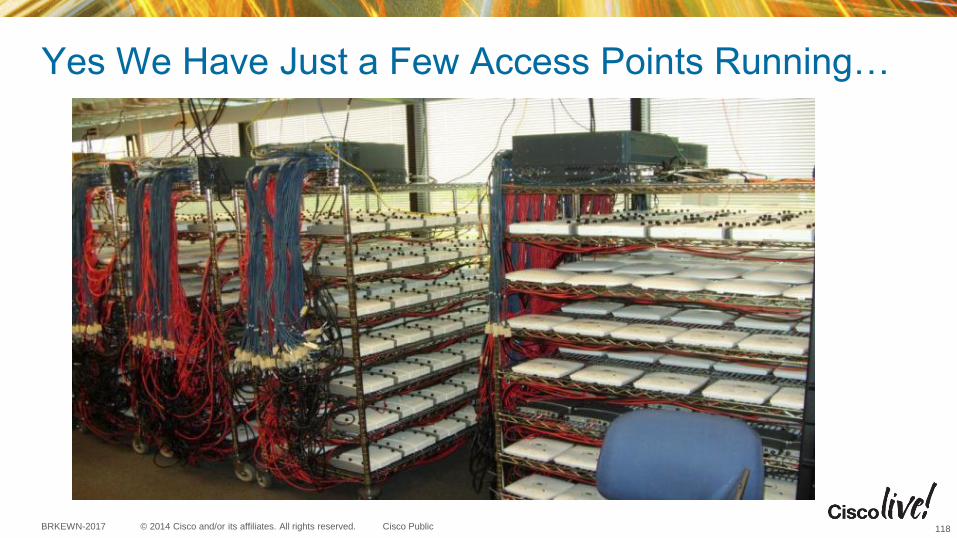
Yes We Have Just a Few Access Points Running…
118

© 2014 Cisco and/or its affiliates. All rights reserved. BRKEWN-2017 Cisco Public
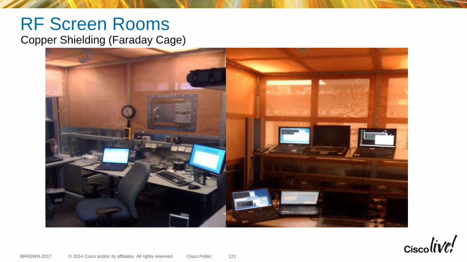
RF Screen Rooms Everywhere Copper Shielding (Faraday Cage)
119
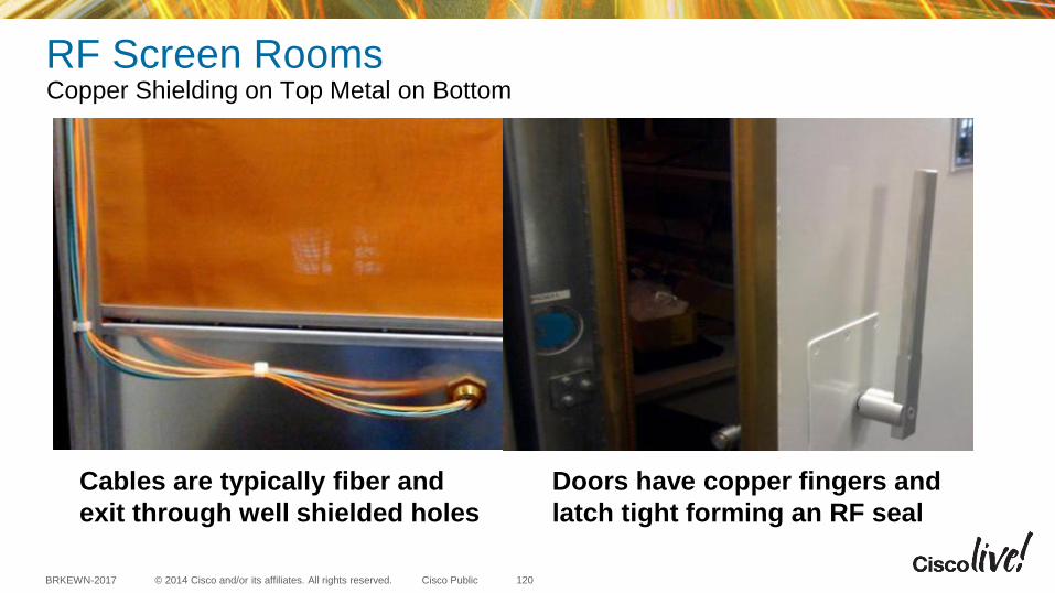
© 2014 Cisco and/or its affiliates. All rights reserved. BRKEWN-2017 Cisco Public
Cables are typically fiber and
exit through well shielded holes
Doors have copper fingers and
latch tight forming an RF seal
RF Screen Rooms Copper Shielding on Top Metal on Bottom
120
© 2014 Cisco and/or its affiliates. All rights reserved. BRKEWN-2017 Cisco Public
RF Screen Rooms Copper Shielding (Faraday Cage)
121
© 2014 Cisco and/or its affiliates. All rights reserved. BRKEWN-2017 Cisco Public
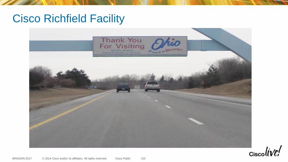
Cisco Richfield Facility
122
Access Point PoE requirements
•

© 2014 Cisco and/or its affiliates. All rights reserved. BRKEWN-2017 Cisco Public
Description AP Functionality PoE
Budget* (Watts)
802.3af E-
PoE
802.3at
PoE+ PWRINJ4
7
0
2
W
PoE+
802.3at
702W – Out of the Box 2x2:2 (both bands) all ports
on including PoE OUT 16.1
PoE
802.3af
702W – Out of the box
PoE OUT - Port is (disabled)
This is the green port on AP
2x2:2 in both bands
15.4 n/a n/a
* This is the power required at the PSE, which is a switch or injector.
Local power supply AIR-PWR-C= may be used. Do not use AIR-PWR-B
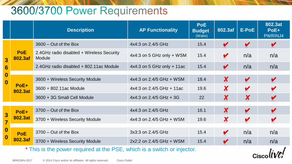
© 2014 Cisco and/or its affiliates. All rights reserved. BRKEWN-2017 Cisco Public
Description AP Functionality PoE
Budget* (Watts)
802.3af E-PoE 802.3at
PoE+ PWRINJ4
3
6
0
0
PoE
802.3af
3600 – Out of the Box 4x4:3 on 2.4/5 GHz 15.4
2.4GHz radio disabled + Wireless Security
Module 4x4:3 on 5 GHz only + WSM 15.4 n/a n/a
2.4GHz radio disabled + 802.11ac Module 4x4:3 on 5 GHz only + 11ac 15.4 n/a n/a
PoE+
802.3at
3600 + Wireless Security Module 4x4:3 on 2.4/5 GHz + WSM 18.4
3600 + 802.11ac Module 4x4:3 on 2.4/5 GHz + 11ac 19.6
3600 + 3G Small Cell Module 4x4:3 on 2.4/5 GHz + 3G 22
3
7
0
0
PoE+
802.3at
3700 – Out of the Box 4x4:3 on 2.4/5 GHz 16.1
3700 + Wireless Security Module 4x4:3 on 2.4/5 GHz + WSM 19.6
PoE
802.3af
3700 – Out of the Box 3x3:3 on 2.4/5 GHz 15.4 n/a n/a
3700 + Wireless Security Module 2x2:2 on 2.4/5 GHz + WSM 15.4 n/a n/a
* This is the power required at the PSE, which is a switch or injector.

© 2014 Cisco and/or its affiliates. All rights reserved. BRKEWN-2017 Cisco Public
Is there a way to see co-channel interference or noise?
Answer: For each AP, you can go to Monitor > AP > choose a radio, and
see the interference levels reported at this AP position, for all channels,
126
© 2014 Cisco and/or its affiliates. All rights reserved. BRKEWN-2017 Cisco Public
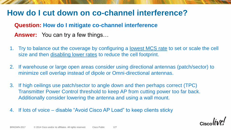
How do I cut down on co-channel interference?
Question: How do I mitigate co-channel interference
Answer: You can try a few things…
1. Try to balance out the coverage by configuring a lowest MCS rate to set or scale the cell
size and then disabling lower rates to reduce the cell footprint.
2. If warehouse or large open areas consider using directional antennas (patch/sector) to
minimize cell overlap instead of dipole or Omni-directional antennas.
3. If high ceilings use patch/sector to angle down and then perhaps correct (TPC)
Transmitter Power Control threshold to keep AP from cutting power too far back.
Additionally consider lowering the antenna and using a wall mount.
4. If lots of voice – disable “Avoid Cisco AP Load” to keep clients sticky
127

© 2014 Cisco and/or its affiliates. All rights reserved. BRKEWN-2017 Cisco Public
Setting 80 MHz channels
128
© 2014 Cisco and/or its affiliates. All rights reserved. BRKEWN-2017 Cisco Public
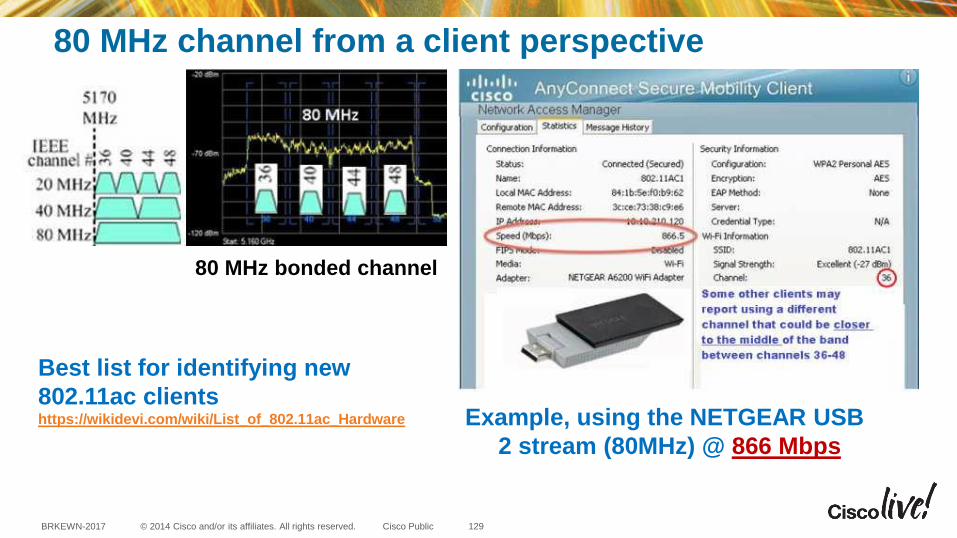
80 MHz channel from a client perspective
Example, using the NETGEAR USB
2 stream (80MHz) @ 866 Mbps
80 MHz bonded channel
Best list for identifying new
802.11ac clients https://wikidevi.com/wiki/List_of_802.11ac_Hardware
129
© 2014 Cisco and/or its affiliates. All rights reserved. BRKEWN-2017 Cisco Public
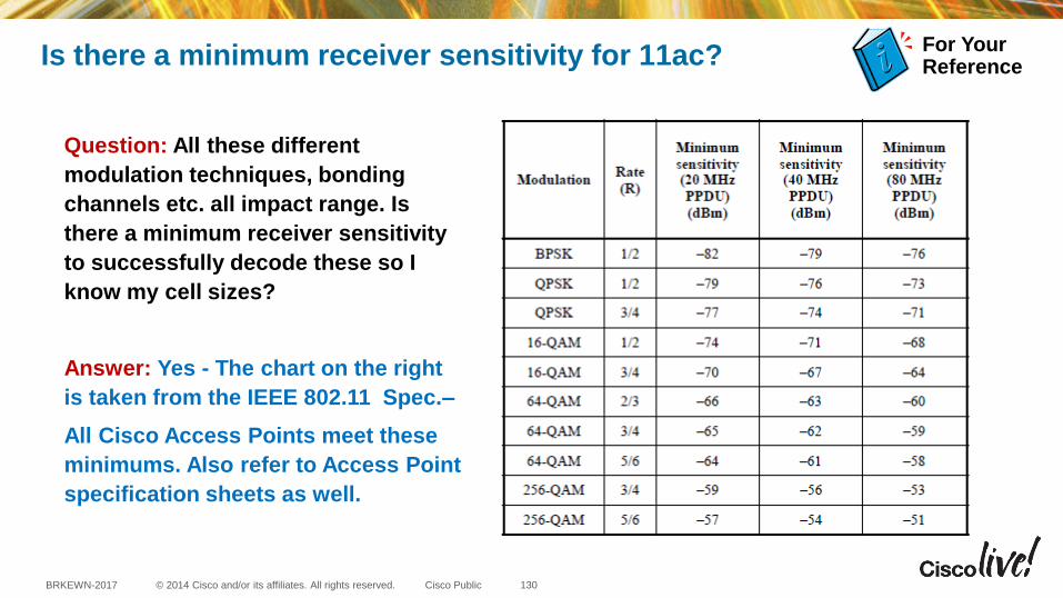
Is there a minimum receiver sensitivity for 11ac?
Question: All these different
modulation techniques, bonding
channels etc. all impact range. Is
there a minimum receiver sensitivity
to successfully decode these so I
know my cell sizes?
Answer: Yes - The chart on the right
is taken from the IEEE 802.11 Spec.–
All Cisco Access Points meet these
minimums. Also refer to Access Point
specification sheets as well.
For Your Reference
130

© 2014 Cisco and/or its affiliates. All rights reserved. BRKEWN-2017 Cisco Public
How does DCA / RRM reuse 80 MHz channels?
Question: Given today in the US, there are only four 80 MHz channels even after
enabling UNII-2 Extended channels. How will the controller reuse these channels
Answer: The short answer is (DCA) performs a calculation based on the 20, 40
and 80MHz Basic Service Set Identification (BSSID’s) used by (11a/n/ac)
protocols as these channels share a common primary channel then it runs lots of
calculations and determines the best method to place these channels. DCA will
always try to align similar primary channel schemes initially when possible and
then tweak using Clear Channel Assessments (CCA)
131
© 2014 Cisco and/or its affiliates. All rights reserved. BRKEWN-2017 Cisco Public
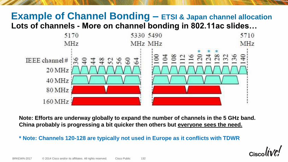
Example of Channel Bonding – ETSI & Japan channel allocation
Lots of channels - More on channel bonding in 802.11ac slides…
Note: Efforts are underway globally to expand the number of channels in the 5 GHz band.
China probably is progressing a bit quicker then others but everyone sees the need.
* Note: Channels 120-128 are typically not used in Europe as it conflicts with TDWR
132


