63
Network Architecture and Functionality
Agenda
Network Architecture
Protocol stacks
Air Interface
System Capacity
Agenda
Network Architecture
Protocol stacks
Air Interface
System Capacity
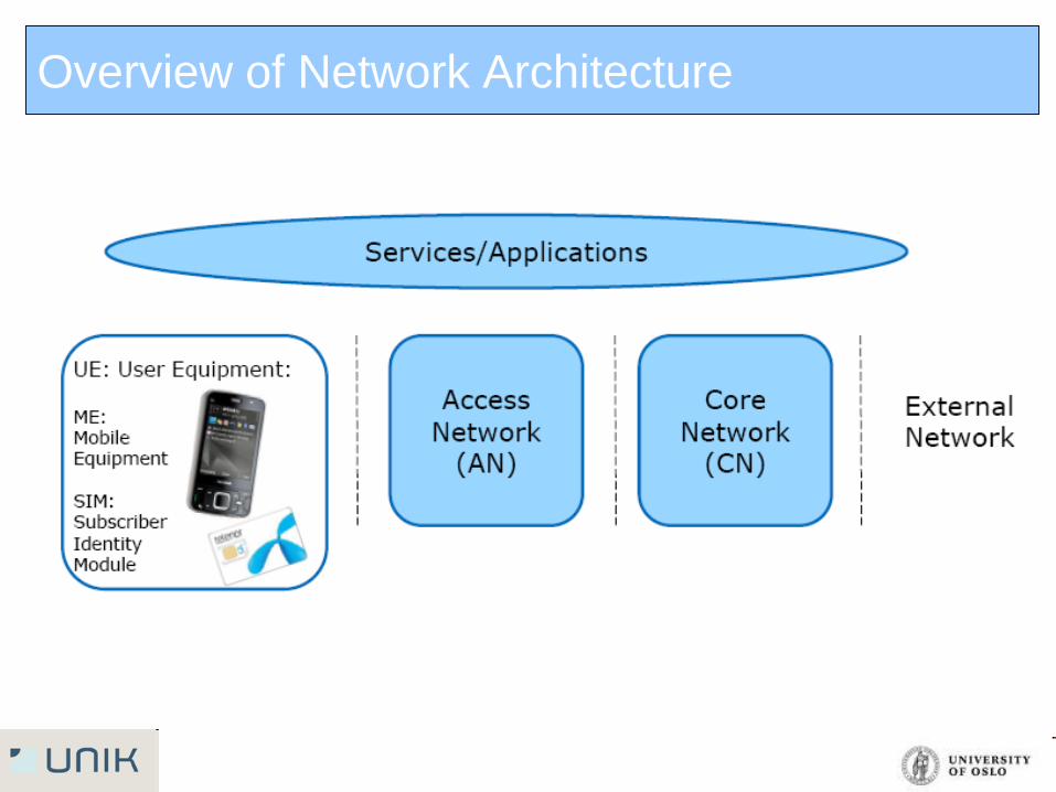
Overview of Network Architecture
Overview of network architecture
A typical mobile network consists of user equeption (UE)/mobile
equepment (ME), access network (AN) and the core network (CN)
UE/ME: Interface with user, handle radio functionality
AN: Communication to and from user equipment handles all radio related
functionality in the network
CN: Communication between AN and external networks, handles all
switching and routing services.
Service and application lie over the network; network operator may
provide them or they come from external (mostly from external)
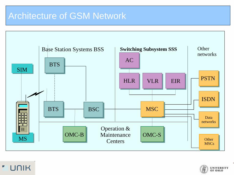
Architecture of GSM Network
Base Station Systems BSS Other networks
Switching Subsystem SSS
Operation & Maintenance
Centers
BTS BSC
OMC-B OMC-S
MSC
ISDN
PSTN
Data networks
AC
HLR VLR EIR
SIM
MS
BTS
Other MSCs
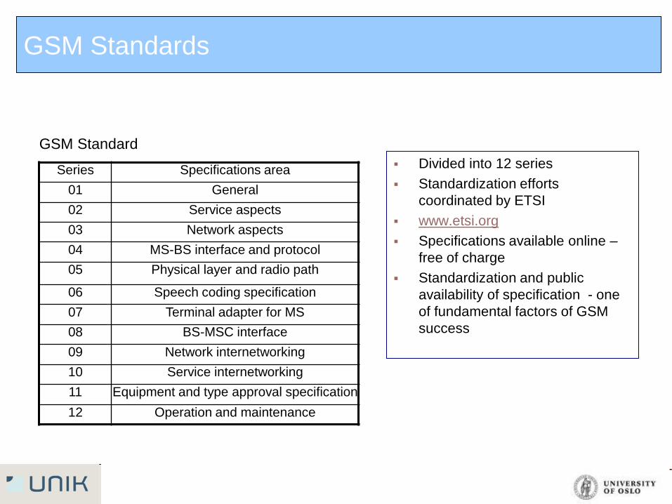
Divided into 12 series
Standardization efforts
coordinated by ETSI
www.etsi.org
Specifications available online –
free of charge
Standardization and public
availability of specification - one
of fundamental factors of GSM
success
Series Specifications area
01 General
02 Service aspects
03 Network aspects
04 MS-BS interface and protocol
05 Physical layer and radio path
06 Speech coding specification
07 Terminal adapter for MS
08 BS-MSC interface
09 Network internetworking
10 Service internetworking
11 Equipment and type approval specification
12 Operation and maintenance
GSM Standard
GSM Standards
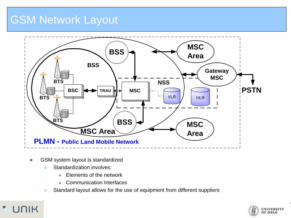
GSM system layout is standardized
Standardization involves:
Elements of the network
Communication Interfaces
Standard layout allows for the use of equipment from different suppliers
MSC
Area
HLR
MSC
Area
VLR
MSCTRAUBSC
BTS
BTS
BSS
MSC Area
BSS
BSSBTS
PSTN
PLMN - Public Land Mobile Network
Gateway
MSCNSS
GSM Network Layout
Page 10
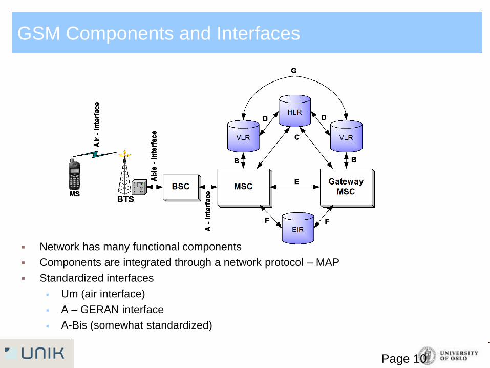
Network has many functional components
Components are integrated through a network protocol – MAP
Standardized interfaces
Um (air interface)
A – GERAN interface
A-Bis (somewhat standardized)
GSM Components and Interfaces
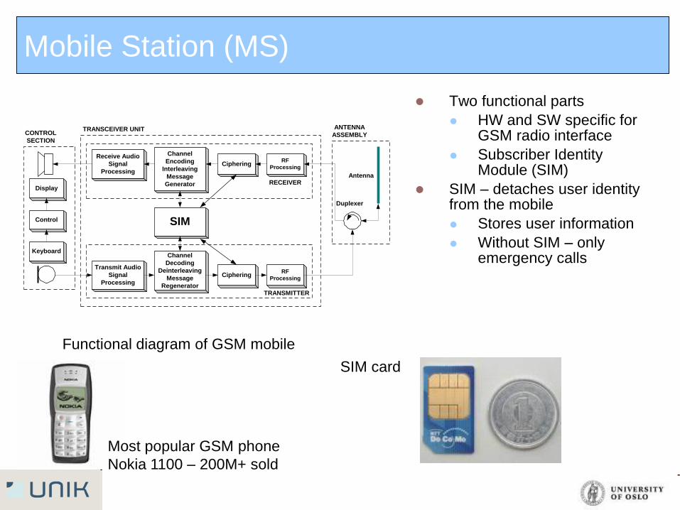
Mobile Station (MS)
Two functional parts
HW and SW specific for GSM radio interface
Subscriber Identity Module (SIM)
SIM – detaches user identity from the mobile
Stores user information
Without SIM – only emergency calls
Functional diagram of GSM mobile
SIM card
Most popular GSM phone
Nokia 1100 – 200M+ sold
Keyboard
Control
Display
Transmit Audio
Signal
Processing
Receive Audio
Signal
Processing
Channel
Decoding
Deinterleaving
Message
Regenerator
Channel
Encoding
Interleaving
Message
Generator
Ciphering
Ciphering
RF
Processing
RF
Processing
SIM
Duplexer
Antenna
ANTENNA
ASSEMBLY
TRANSMITTER
RECEIVER
TRANSCEIVER UNITCONTROL
SECTION
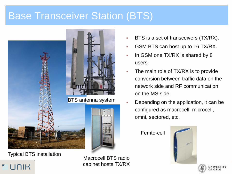
Base Transceiver Station (BTS)
BTS is a set of transceivers (TX/RX).
GSM BTS can host up to 16 TX/RX.
In GSM one TX/RX is shared by 8
users.
The main role of TX/RX is to provide
conversion between traffic data on the
network side and RF communication
on the MS side.
Depending on the application, it can be
configured as macrocell, microcell,
omni, sectored, etc.
Typical BTS installation
BTS antenna system
Macrocell BTS radio
cabinet hosts TX/RX
Femto-cell
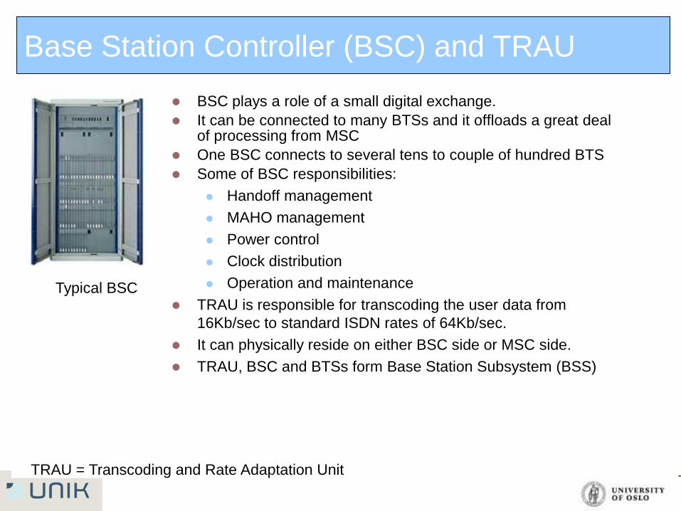
Base Station Controller (BSC) and TRAU
BSC plays a role of a small digital exchange.
It can be connected to many BTSs and it offloads a great deal of processing from MSC
One BSC connects to several tens to couple of hundred BTS
Some of BSC responsibilities:
Handoff management
MAHO management
Power control
Clock distribution
Operation and maintenance
TRAU is responsible for transcoding the user data from
16Kb/sec to standard ISDN rates of 64Kb/sec.
It can physically reside on either BSC side or MSC side.
TRAU, BSC and BTSs form Base Station Subsystem (BSS)
Typical BSC
TRAU = Transcoding and Rate Adaptation Unit
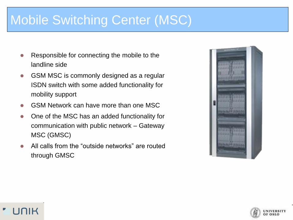
Mobile Switching Center (MSC)
Responsible for connecting the mobile to the
landline side
GSM MSC is commonly designed as a regular
ISDN switch with some added functionality for
mobility support
GSM Network can have more than one MSC
One of the MSC has an added functionality for
communication with public network – Gateway
MSC (GMSC)
All calls from the “outside networks” are routed
through GMSC
Register- HLR/VLR
HLR – Home Location Register
Database for permanent or semi-
permanent data associated with the
user
Logically, there is only one HLR per
network
Typical information stored in HLR:
International Mobile Service
Identification Number (IMSI), service
subscription information,
supplementary services, current
location of the subscriber, etc.
HLR is usually implemented as an
integral part of MSC
VLR – Visitor Location register
Temporary database that keeps the
information about the users within the
service area of the MSC
Usually there is one VLR per MSC
The main task of the VLR is to reduce
the number of queries to HLR. When
the mobile, registers on the system its
information is copied from HLR to VLR
VLR is usually integrated with the
switch
AuC/EIR
AUC – Authentication center
Integral part of HLR
Can be only SW function or
special build HW with enhanced
security (within HLR)
For security 3 algorithms are
specified in GSM:
-A3 algorithm for authentication
- A5 algorithm for encryption
- A8 algorithm for key generation
EIR – Equipment Identity Registry
Responsible for tracking equipment
and eligibility for service
Maintains three lists
White list – approved mobile
types
Black list – barred mobile types
Gray list – tracked mobile types
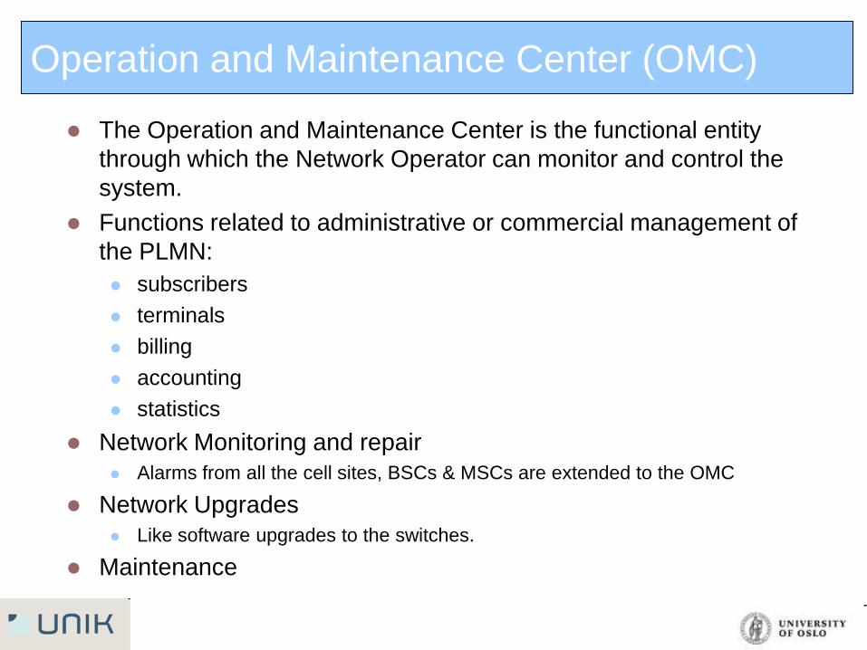
Operation and Maintenance Center (OMC)
The Operation and Maintenance Center is the functional entity
through which the Network Operator can monitor and control the
system.
Functions related to administrative or commercial management of
the PLMN:
subscribers
terminals
billing
accounting
statistics
Network Monitoring and repair
Alarms from all the cell sites, BSCs & MSCs are extended to the OMC
Network Upgrades
Like software upgrades to the switches.
Maintenance
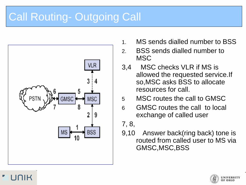
Call Routing- Outgoing Call
1. MS sends dialled number to BSS
2. BSS sends dialled number to MSC
3,4 MSC checks VLR if MS is allowed the requested service.If so,MSC asks BSS to allocate resources for call.
5 MSC routes the call to GMSC
6 GMSC routes the call to local exchange of called user
7, 8,
9,10 Answer back(ring back) tone is routed from called user to MS via GMSC,MSC,BSS
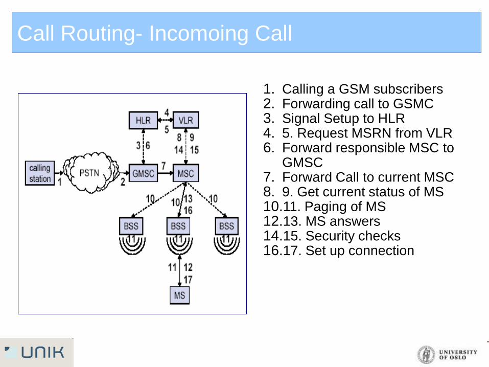
Call Routing- Incomoing Call
1. Calling a GSM subscribers 2. Forwarding call to GSMC 3. Signal Setup to HLR 4. 5. Request MSRN from VLR 6. Forward responsible MSC to
GMSC 7. Forward Call to current MSC 8. 9. Get current status of MS 10.11. Paging of MS 12.13. MS answers 14.15. Security checks 16.17. Set up connection
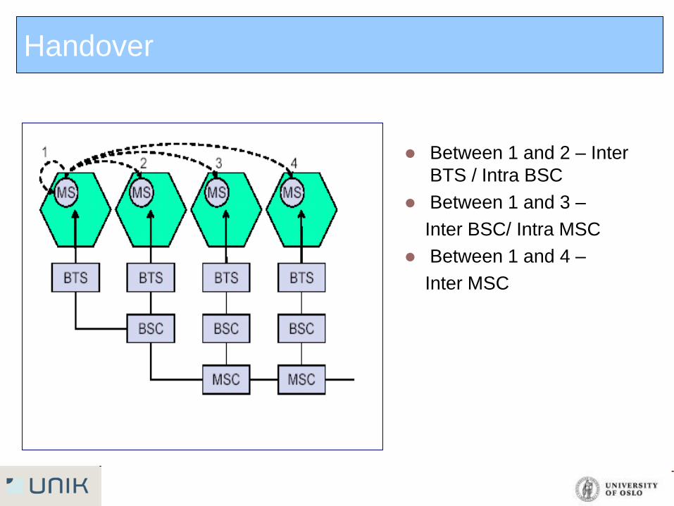
Handover
Between 1 and 2 – Inter
BTS / Intra BSC
Between 1 and 3 –
Inter BSC/ Intra MSC
Between 1 and 4 –
Inter MSC
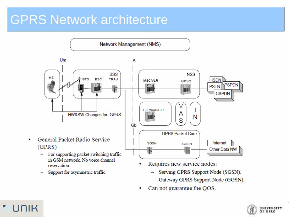
GPRS Network architecture
GPRS is another new transmission capability for GSM that will be
especially developed to accommodate for high-bandwidth data traffic
GPRS handle rates from 14.4Kbps using just one TDMA slot, and up
to 115Kbps using all eight time slots
It introduces packet switching - can accommodate the data traffic
characteristics
PCU (Packet Control Unit): It decides whether the data is to be routed
to the packet switched or circuit switched network
SGSN (Serving GPRS Support Node): It is functionaing same as
MSC but in the packet switched domain. It is gateway to the services
within the network
GGSN (Gateway GPRS Support Node): Gateway between
GPRS/EDGE network and external packet switched network. It is a
combination of gateway, router and firewall.
General Packed Radio Data (GPRS)
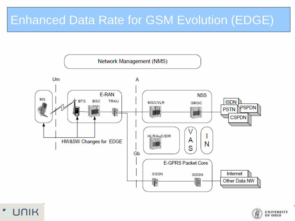
Enhanced Data Rate for GSM Evolution (EDGE)
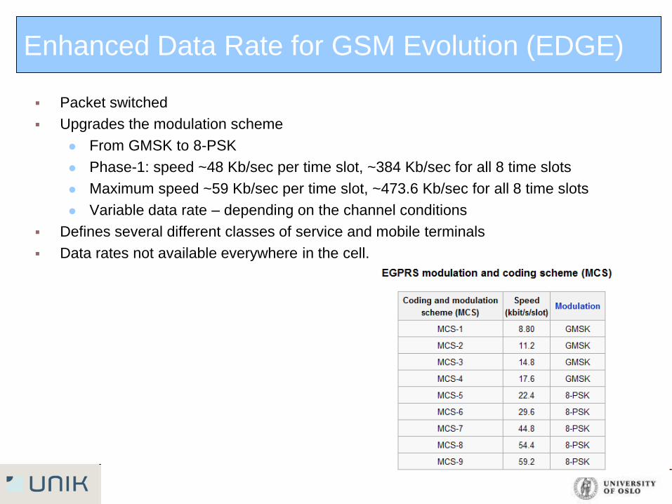
Packet switched
Upgrades the modulation scheme
From GMSK to 8-PSK
Phase-1: speed ~48 Kb/sec per time slot, ~384 Kb/sec for all 8 time slots
Maximum speed ~59 Kb/sec per time slot, ~473.6 Kb/sec for all 8 time slots
Variable data rate – depending on the channel conditions
Defines several different classes of service and mobile terminals
Data rates not available everywhere in the cell.
Enhanced Data Rate for GSM Evolution (EDGE)
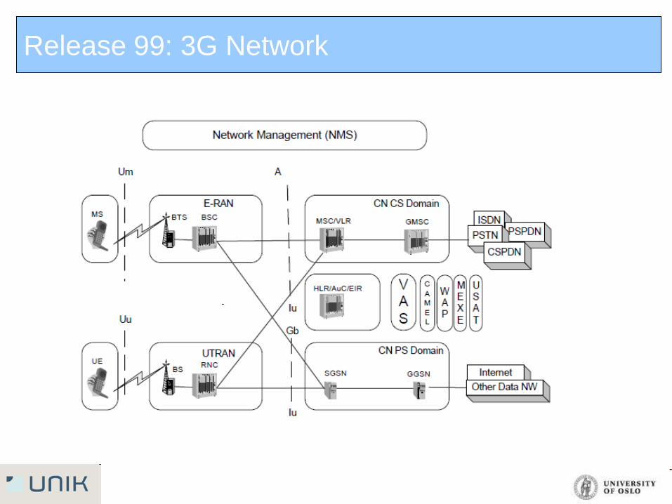
Release 99: 3G Network
Release 99 standardization introduced new Radio Interface for 3G
NodeB for 3G Access Network-similar to BTS in 2G
RNC (Radio Network Controller) as similar to BSC in 2G
Interoperability with GSM
Possibility to re-use 2G MSC/VLR and HLR also for 3G
Release 99: 3G Network
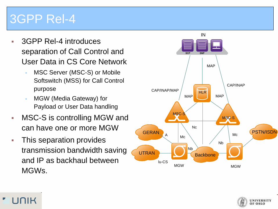
3GPP Rel-4 introduces
separation of Call Control and
User Data in CS Core Network
MSC Server (MSC-S) or Mobile
Softswitch (MSS) for Call Control
purpose
MGW (Media Gateway) for
Payload or User Data handling
MSC-S is controlling MGW and
can have one or more MGW
This separation provides
transmission bandwidth saving
and IP as backhaul between
MGWs.
3GPP Rel-4
MAP
MAP
CAP/INAP
CAP/INAP/MAP
Mc
Nb
Nb
Mc A
lu-CS
MAP
Nc
IN
MGW MGW
MSC-S MSC-S
HLR
GERAN
UTRAN
PSTN/ISDN
Backbone
SAE GW
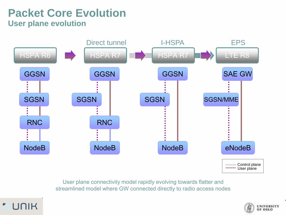
Packet Core Evolution User plane evolution
User plane connectivity model rapidly evolving towards flatter and
streamlined model where GW connected directly to radio access nodes
GGSN
RNC
NodeB
GGSN
SGSN
RNC
NodeB
SGSN
Direct tunnel
GGSN
SGSN
I-HSPA
SGSN/MME
NodeB
EPS
eNodeB
HSPA R6 HSPA R7 HSPA R7 LTE R8
User plane Control plane
Agenda
Network Architecture
Protocol stacks
Air Interface
System Capacity
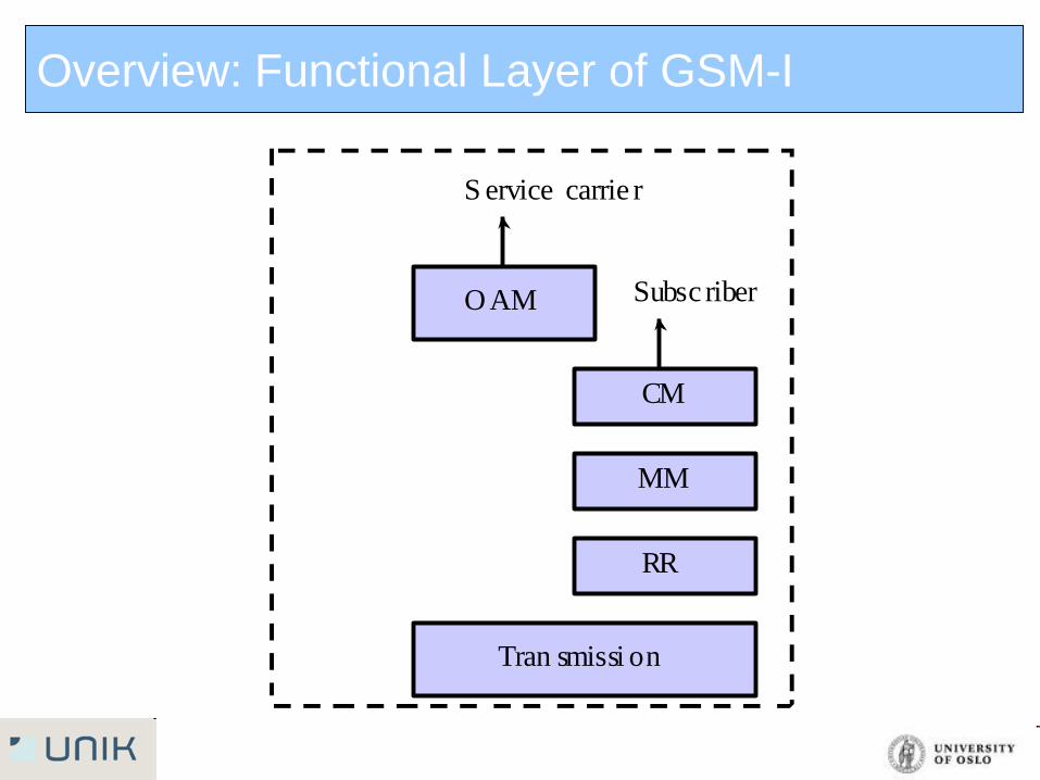
Overview: Functional Layer of GSM-I
O AM
S ervice carrie r
CM
MM
RR
Subsc riber
Tran smissi on
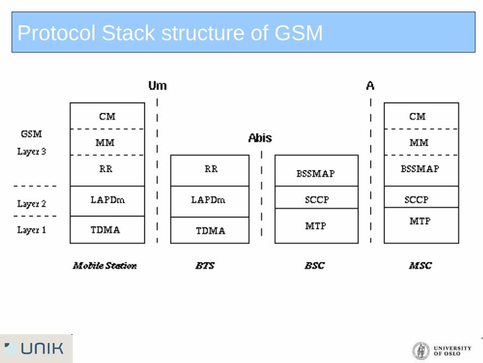
Protocol Stack structure of GSM
Protocol structure of GSM
Layer 1(physical layer) uses the channel structures over the air
interface.
Layer 2(data link layer): Across the Um interface, the data link layer is
a modified version of the LAPD protocol used in ISDN, called LAPDm.
Across the A interface, the Message Transfer Part layer 2 of Signalling
System Number 7 is used.
Layer 3 is divided into 3 parts
Radio Resources (RR) Management
Controls the setup, maintenance, and termination of radio and fixed channels,
including handovers.
Mobility Management (MM)
Manages the location updating and registration procedures, as well as security and
authentication.
Connection Management (CM)
Handles general call control, similar to CCITT Recommendation Q.931, and
manages Supplementary Services and the Short Message Service.
Agenda
Network architecture
Protocol stacks
Air Interface
System Capacity
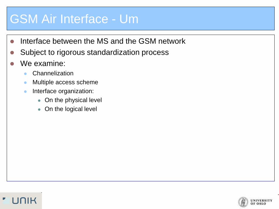
GSM Air Interface - Um
Interface between the MS and the GSM network
Subject to rigorous standardization process
We examine:
Channelization
Multiple access scheme
Interface organization:
On the physical level
On the logical level
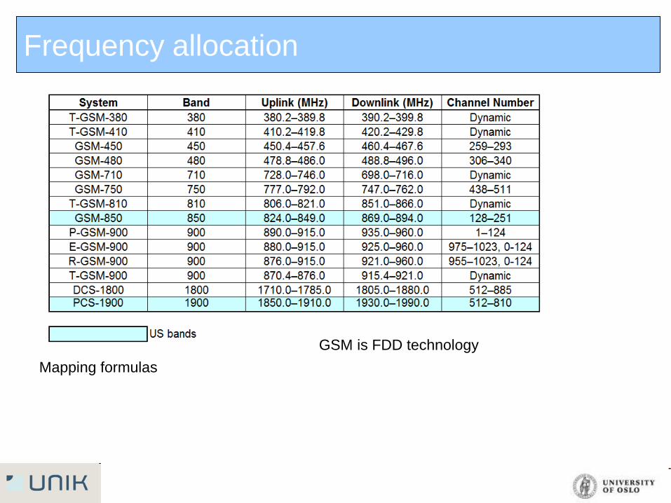
Frequency allocation
Mapping formulas
GSM is FDD technology
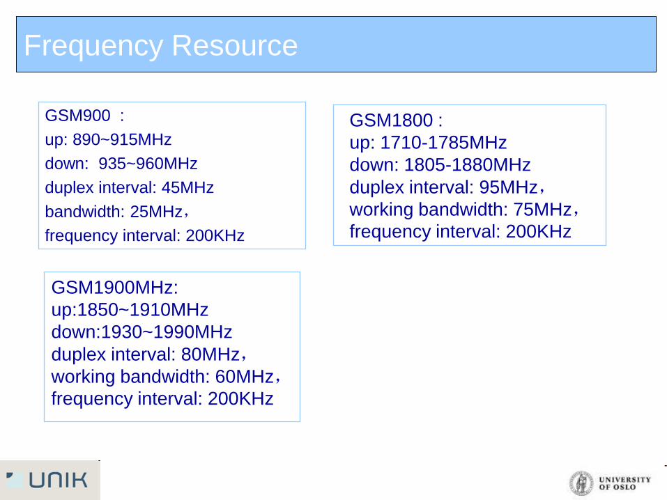
Frequency Resource
GSM900 :
up: 890~915MHz
down: 935~960MHz
duplex interval: 45MHz
bandwidth: 25MHz,
frequency interval: 200KHz
GSM1800 :
up: 1710-1785MHz
down: 1805-1880MHz
duplex interval: 95MHz,
working bandwidth: 75MHz,
frequency interval: 200KHz
GSM1900MHz:
up:1850~1910MHz
down:1930~1990MHz
duplex interval: 80MHz,
working bandwidth: 60MHz,
frequency interval: 200KHz
Frequency Resource
1800MHz
1900MHz
900MHz
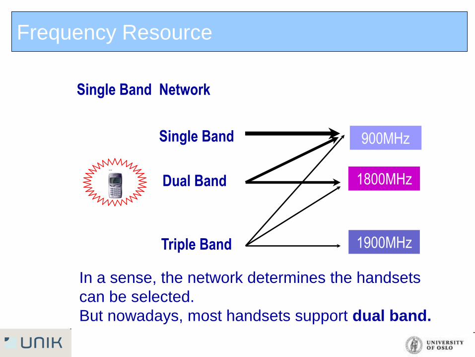
Single Band Network
Single Band
Dual Band
Triple Band
In a sense, the network determines the handsets
can be selected.
But nowadays, most handsets support dual band.
Frequency Resource
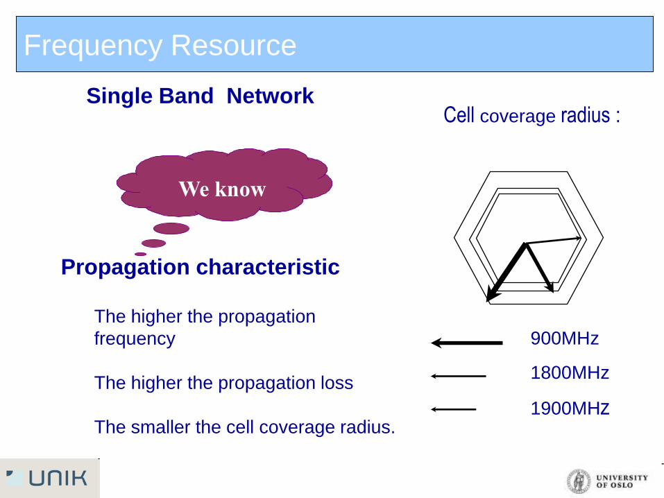
Propagation characteristic
Cell coverage radius :
The higher the propagation
frequency
The higher the propagation loss
The smaller the cell coverage radius.
900MHz
1800MHz
1900MHz
Single Band Network
We know
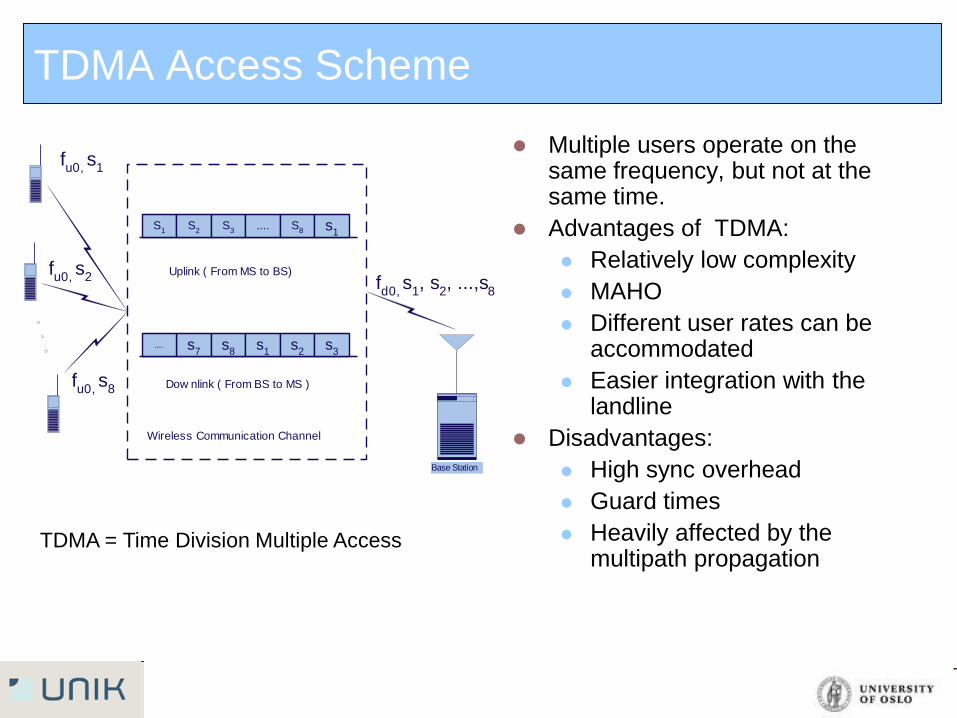
TDMA Access Scheme
Multiple users operate on the same frequency, but not at the same time.
Advantages of TDMA:
Relatively low complexity
MAHO
Different user rates can be accommodated
Easier integration with the landline
Disadvantages:
High sync overhead
Guard times
Heavily affected by the multipath propagation
Uplink ( From MS to BS)
Wireless Communication Channel
Dow nlink ( From BS to MS )
Base Station
fu0,
s1
fd0,
s1, s
2, ...,s
8
S1
S2
S3
.... S8 s
1
s7
s8
.... s1
s2
s3
fu0,
s2
fu0,
s8
TDMA = Time Division Multiple Access
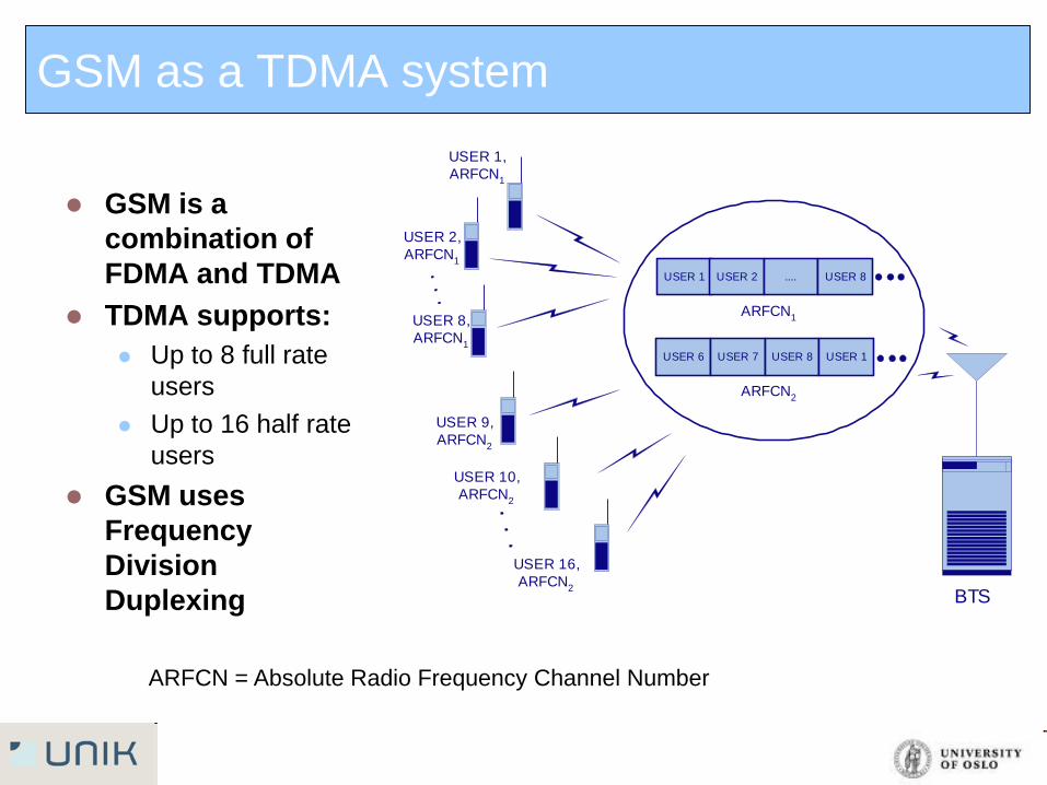
GSM as a TDMA system
GSM is a
combination of
FDMA and TDMA
TDMA supports:
Up to 8 full rate
users
Up to 16 half rate
users
GSM uses
Frequency
Division
Duplexing
BTS
USER 1 USER 2 .... USER 8
USER 6 USER 7 USER 8 USER 1
USER 1,
ARFCN1
USER 2,
ARFCN1
USER 8,
ARFCN1
USER 9,
ARFCN2
USER 10,
ARFCN2
USER 16,
ARFCN2
ARFCN1
ARFCN2
ARFCN = Absolute Radio Frequency Channel Number
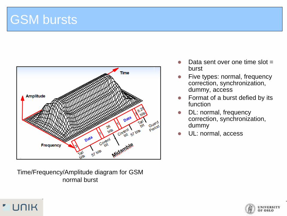
GSM bursts
Data sent over one time slot = burst
Five types: normal, frequency correction, synchronization, dummy, access
Format of a burst defied by its function
DL: normal, frequency correction, synchronization, dummy
UL: normal, access
Time/Frequency/Amplitude diagram for GSM
normal burst
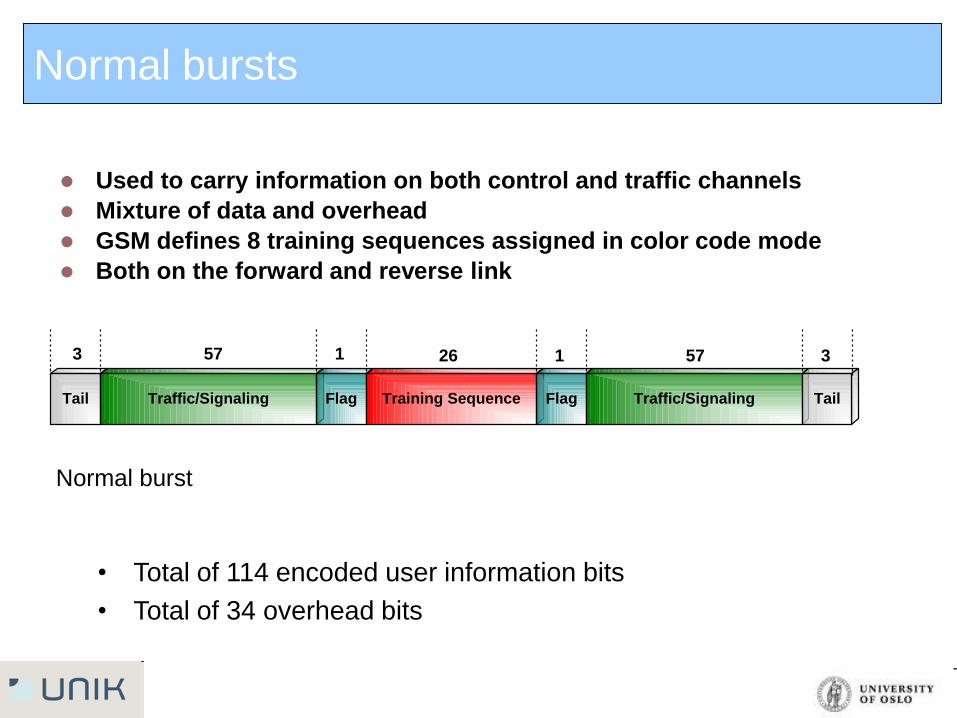
Used to carry information on both control and traffic channels
Mixture of data and overhead
GSM defines 8 training sequences assigned in color code mode
Both on the forward and reverse link
• Total of 114 encoded user information bits
• Total of 34 overhead bits
Tail Traffic/Signaling Flag Training Sequence Flag Traffic/Signaling Tail
3 57 1 26 1 57 3
Normal burst
Normal bursts
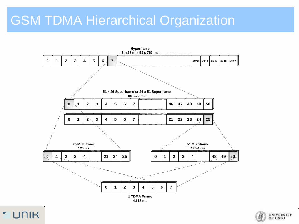
GSM TDMA Hierarchical Organization
0 1 2 3 4 5 6 7 21 22 23 24 25
1 TDMA Frame
4.615 ms
26 Multiframe
120 ms
51 Multiframe
235.4 ms
51 x 26 Superframe or 26 x 51 Superframe
6s 120 ms
Hyperframe
3 h 28 min 53 s 760 ms
0 1 2 3 4 48 49 50
0 1 2 3 4 5 6 7 2043 2044 2045 2046 2047
0 1 2 3 4 5 6 7 46 47 48 49 50
0 1 2 3 4 23 24 25
0 1 2 3 4 5 6 7
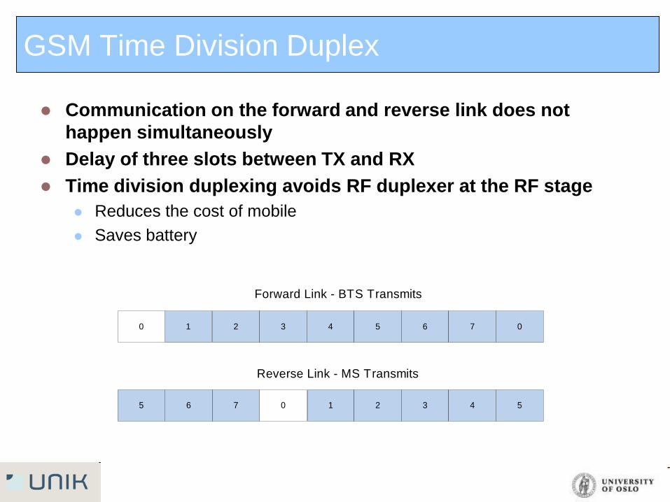
GSM Time Division Duplex
Communication on the forward and reverse link does not
happen simultaneously
Delay of three slots between TX and RX
Time division duplexing avoids RF duplexer at the RF stage
Reduces the cost of mobile
Saves battery
0
1 2 3 4 5 6 7 00
1 2 3 4 5765
Forward Link - BTS Transmits
Reverse Link - MS Transmits
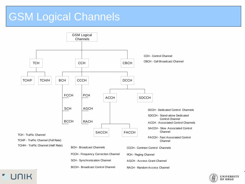
GSM Logical Channels
GSM Logical
Channels
TCH
TCH/F TCH/H
CCH
BCH CCCH DCCH
CBCH
ACCH SDCCH
FACCHSACCH
FCCH
SCH
BCCH
PCH
AGCH
RACH
TCH - Traff ic Channel
TCH/F - Traff ic Channel (Full Rate)
TCH/H - Traff ic Channel (Half Rate)BCH - Broadcast Channels
FCCH - Frequency Correction Channel
SCH - Synchronization Channel
BCCH - Broadcast Control Channel
CCCH - Common Control Channels
PCH - Paging Channel
AGCH - Access Grant Channel
RACH - Random Access Channel
DCCH - Dedicated Control Channels
SDCCH - Stand-alone Dedicated
Control Channel
ACCH - Associated Control Channels
SACCH - Slow Associated Control
Channel
FACCH - Fast Associated Control
Channel
CCH - Control Channel
CBCH - Cell Broadcast Channel
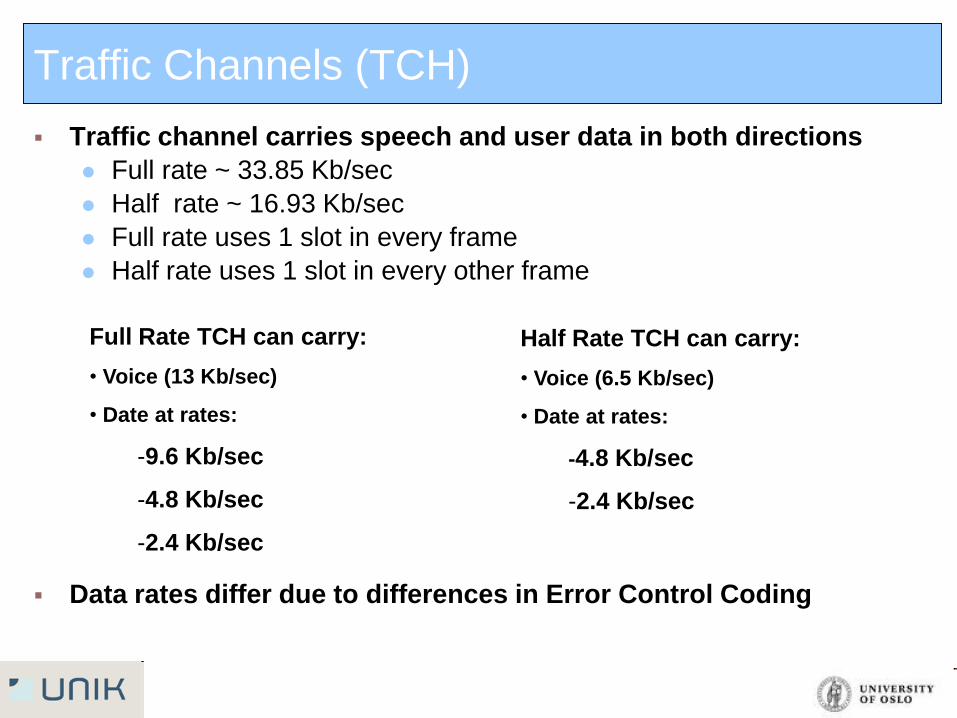
Traffic channel carries speech and user data in both directions
Full rate ~ 33.85 Kb/sec
Half rate ~ 16.93 Kb/sec
Full rate uses 1 slot in every frame
Half rate uses 1 slot in every other frame
Data rates differ due to differences in Error Control Coding
Traffic Channels (TCH)
Full Rate TCH can carry:
• Voice (13 Kb/sec)
• Date at rates:
-9.6 Kb/sec
-4.8 Kb/sec
-2.4 Kb/sec
Half Rate TCH can carry:
• Voice (6.5 Kb/sec)
• Date at rates:
-4.8 Kb/sec
-2.4 Kb/sec
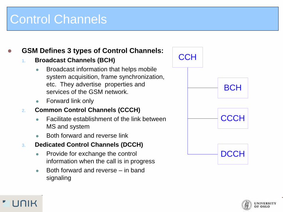
GSM Defines 3 types of Control Channels:
1. Broadcast Channels (BCH)
Broadcast information that helps mobile
system acquisition, frame synchronization,
etc. They advertise properties and
services of the GSM network.
Forward link only
2. Common Control Channels (CCCH)
Facilitate establishment of the link between
MS and system
Both forward and reverse link
3. Dedicated Control Channels (DCCH)
Provide for exchange the control
information when the call is in progress
Both forward and reverse – in band
signaling
CCH
BCH
CCCH
DCCH
Control Channels
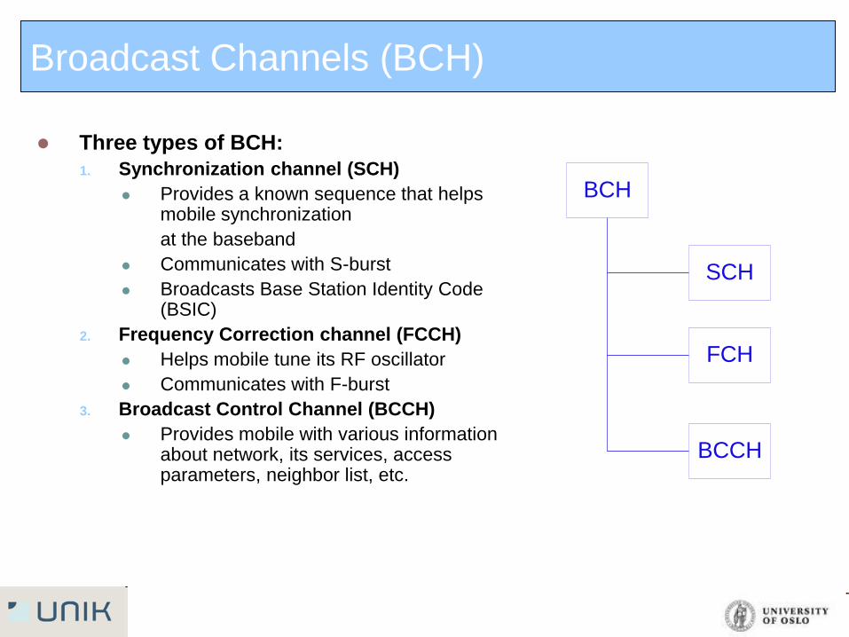
Broadcast Channels (BCH)
Three types of BCH:
1. Synchronization channel (SCH)
Provides a known sequence that helps mobile synchronization
at the baseband
Communicates with S-burst
Broadcasts Base Station Identity Code (BSIC)
2. Frequency Correction channel (FCCH)
Helps mobile tune its RF oscillator
Communicates with F-burst
3. Broadcast Control Channel (BCCH)
Provides mobile with various information about network, its services, access parameters, neighbor list, etc.
BCH
SCH
FCH
BCCH
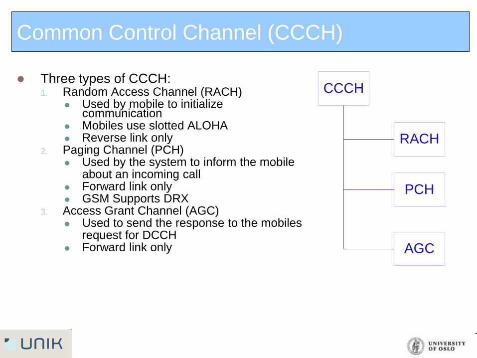
Common Control Channel (CCCH)
Three types of CCCH: 1. Random Access Channel (RACH)
Used by mobile to initialize communication
Mobiles use slotted ALOHA Reverse link only
2. Paging Channel (PCH) Used by the system to inform the mobile about an incoming call Forward link only GSM Supports DRX
3. Access Grant Channel (AGC) Used to send the response to the mobiles request for DCCH Forward link only
CCCH
RACH
PCH
AGC
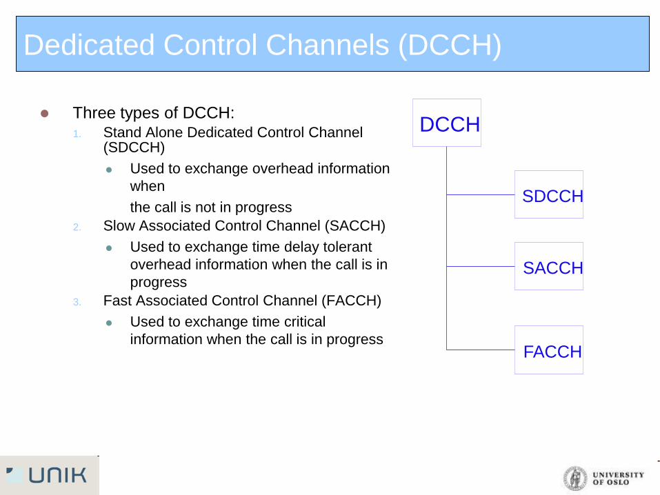
Dedicated Control Channels (DCCH)
Three types of DCCH: 1. Stand Alone Dedicated Control Channel
(SDCCH)
Used to exchange overhead information
when
the call is not in progress
2. Slow Associated Control Channel (SACCH)
Used to exchange time delay tolerant
overhead information when the call is in
progress
3. Fast Associated Control Channel (FACCH)
Used to exchange time critical
information when the call is in progress
DCCH
SDCCH
SACCH
FACCH
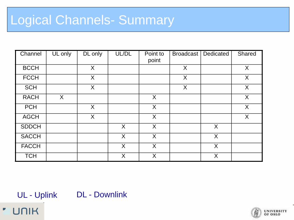
UL - Uplink DL - Downlink
Channel UL only DL only UL/DL Point to point
Broadcast Dedicated Shared
BCCH X X X
FCCH X X X
SCH X X X
RACH X X X
PCH X X X
AGCH X X X
SDDCH X X X
SACCH X X X
FACCH X X X
TCH X X X
Logical Channels- Summary
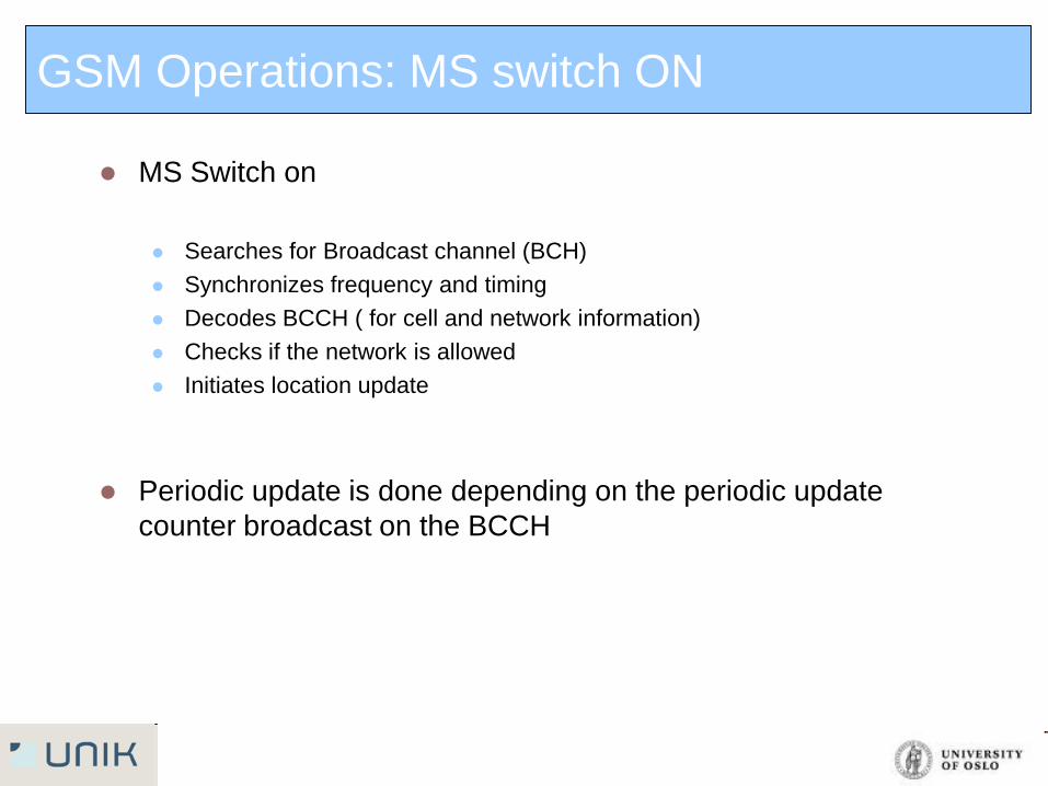
GSM Operations: MS switch ON
MS Switch on
Searches for Broadcast channel (BCH)
Synchronizes frequency and timing
Decodes BCCH ( for cell and network information)
Checks if the network is allowed
Initiates location update
Periodic update is done depending on the periodic update
counter broadcast on the BCCH
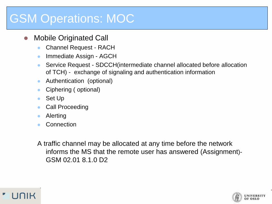
GSM Operations: MOC
Mobile Originated Call
Channel Request - RACH
Immediate Assign - AGCH
Service Request - SDCCH(intermediate channel allocated before allocation
of TCH) - exchange of signaling and authentication information
Authentication (optional)
Ciphering ( optional)
Set Up
Call Proceeding
Alerting
Connection
A traffic channel may be allocated at any time before the network
informs the MS that the remote user has answered (Assignment)-
GSM 02.01 8.1.0 D2
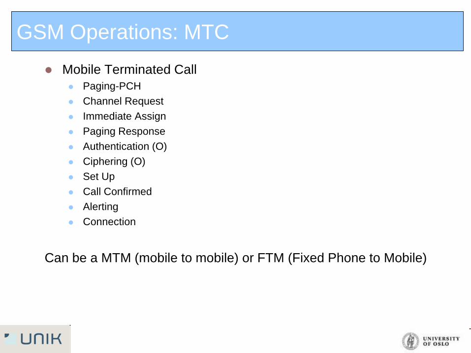
GSM Operations: MTC
Mobile Terminated Call
Paging-PCH
Channel Request
Immediate Assign
Paging Response
Authentication (O)
Ciphering (O)
Set Up
Call Confirmed
Alerting
Connection
Can be a MTM (mobile to mobile) or FTM (Fixed Phone to Mobile)
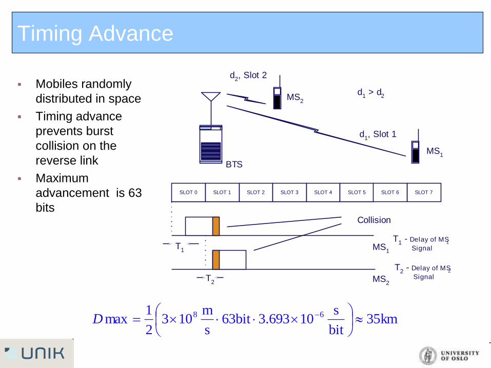
Timing Advance
Mobiles randomly
distributed in space
Timing advance
prevents burst
collision on the
reverse link
Maximum
advancement is 63
bits
BTS
SLOT 0 SLOT 1 SLOT 2 SLOT 3 SLOT 4 SLOT 5
MS2
MS1
d2, Slot 2
d1, Slot 1
d1 > d
2MS2
MS1
T1
T2
Collision
T1 - Delay of MS
1
Signal
T2 - Delay of MS
2
Signal
SLOT 7SLOT 6
km35bit
s10693.3bit63
s
m103
2
1max 68
D
Sampling,
Quantization and
source encoding
Channel
Encoding
(Error Correction
Coding)
Interleaving
Burst
Formating
Mapping
De-
Ciphering
Modulation
De-Modulation
Ciphering
Burst
Formating
Mapping
De
-Interleaving
Channel
Decoding
(Error Correction )
Source Decoding
and Waveform
Generation
Um
Interface
Voice
Signal
Voice
Signal
Transmit Side
Receive Side
As a digital TDMA technology GSM implements extensive signal
processing
Signal Processing- From voice to Radio waves
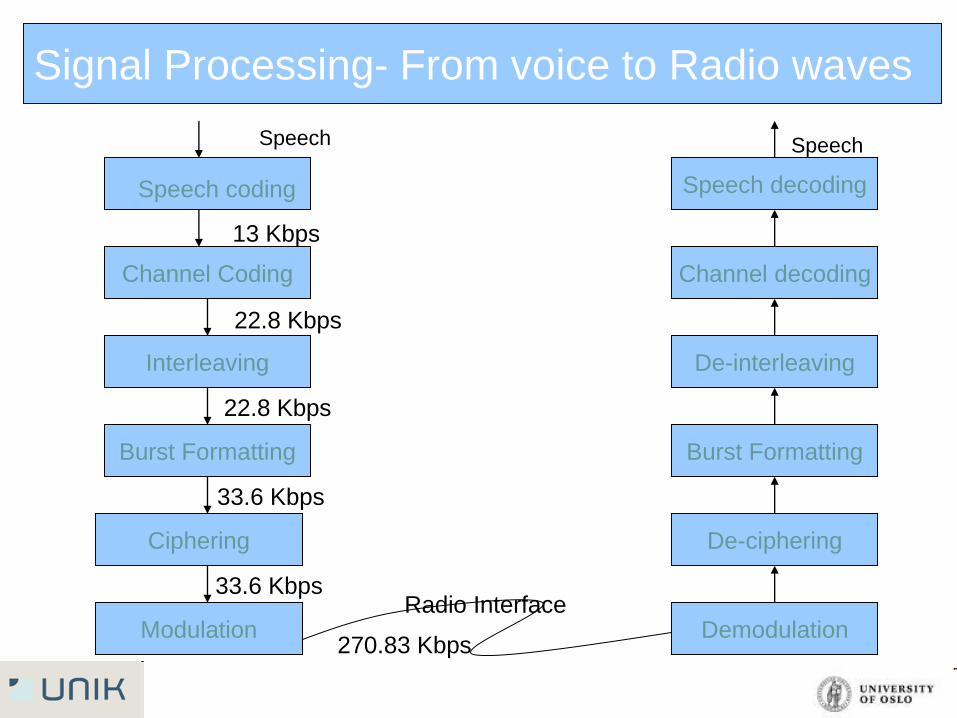
Signal Processing- From voice to Radio waves
Speech decoding
Channel decoding
De-interleaving
Burst Formatting
De-ciphering
Demodulation Modulation
Ciphering
Burst Formatting
Interleaving
Channel Coding
Speech coding
Radio Interface
Speech Speech
13 Kbps
22.8 Kbps
22.8 Kbps
33.6 Kbps
33.6 Kbps
270.83 Kbps
Agenda
Network architecture
Protocol stacks
Air Interface
System Capacity
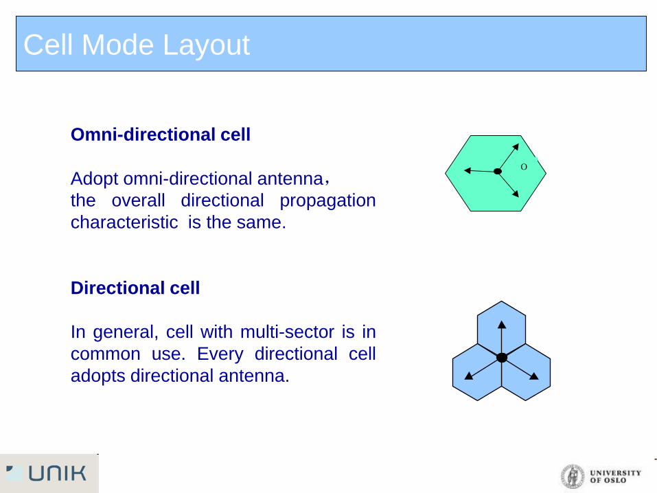
Cell Mode Layout
O
Omni-directional cell
Adopt omni-directional antenna,
the overall directional propagation
characteristic is the same.
Directional cell
In general, cell with multi-sector is in
common use. Every directional cell
adopts directional antenna.
BTS Mode
Capacity
When the traffic is very low, and no possibility for quick increment,
Omni-directional cell is used in common. Otherwise, we suggest to
adopt the sector cell.
Note: TRX-transceiver,each TRX handles 1 frequency.
Coverage Area
Sector cell is often used to enlarge the cell coverage radius because
of the higher antenna gain.
For special coverage ,such as road coverage, two-sector cell is
adopted firstly.
System Capacity
Erlang :
the traffic intensity of a totally occupied channel (i.e. the call hour
of a unit hour or the call minute of a unit minute). For example,
the traffic of a channel occupied for 30 minutes in an hour is 0.5
Erlang)
GOS:
defined as the probability of call blocking or the probability when
the call delay time is longer than a given queuing time.
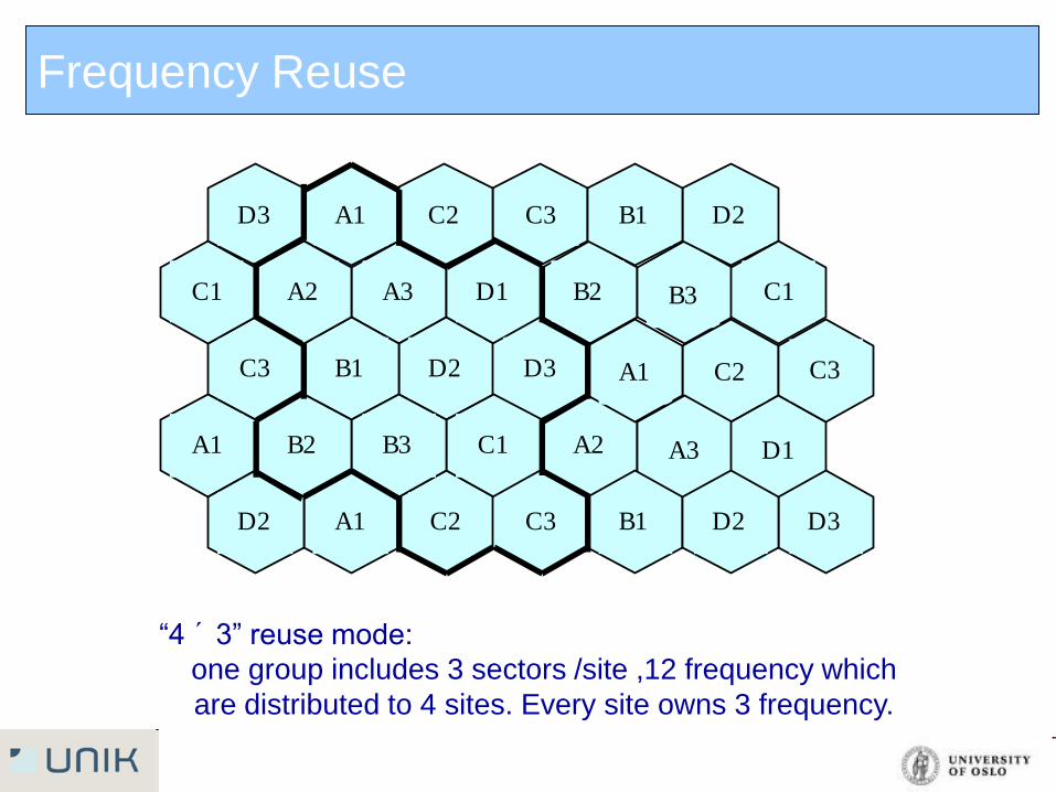
Frequency Reuse
“4 ´ 3” reuse mode:
one group includes 3 sectors /site ,12 frequency which
are distributed to 4 sites. Every site owns 3 frequency.
A3
D2B1
C3
B2D1
D3
A2C1
B3
C2A1
B3
C2A1
A3
A1B1
D1
D3D2
C3
B2A1
C3D2
C3
C1
D2B1C2A1
A2C1
D3
Frequency Reuse
A3
C2B1
B3
A2C1
C3
B2A1
A3
C2B1
B3
A2C1
B3
A1C1
A1
A3A2
C3
B2A1
A3A3
C3
C1
B2A1B2A1
A2C1
B3
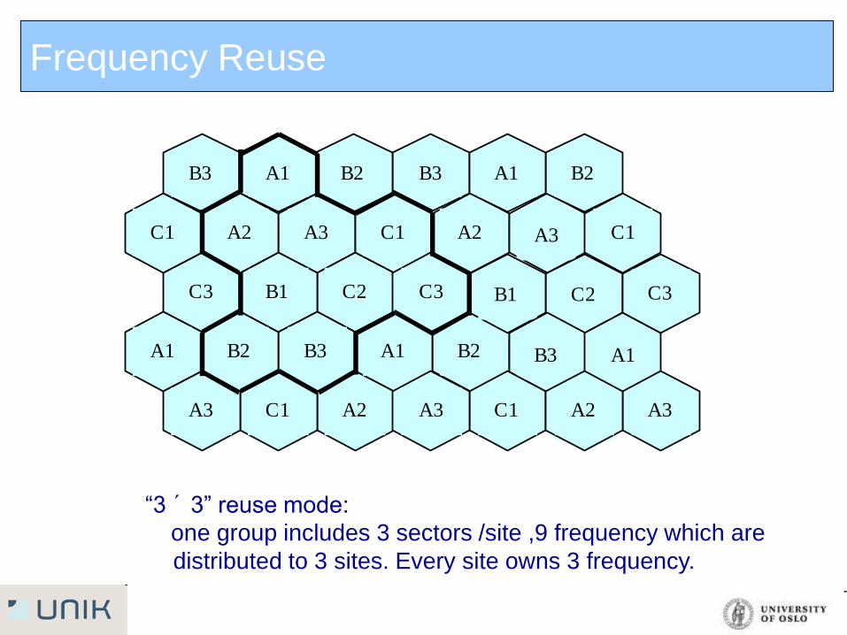
“3 ´ 3” reuse mode:
one group includes 3 sectors /site ,9 frequency which are
distributed to 3 sites. Every site owns 3 frequency.