25
Unit 10 Measuring Instruments

Unit 10
Measuring Instruments
Unit 10
Measuring Instruments
Objectives:
• Discuss the operation of a d’Arsonval meter movement.
• Connect a voltmeter to a circuit.
• Read an analog multimeter.
• Connect an ammeter.
• Measure resistance using an ohmmeter.

Unit 10
Measuring Instruments
Analog meters are characterized by the
fact that they use a pointer and scale to
indicate their value.
• One of the common types of meters uses
the d’Arsonval type of meter movement.
• Analog meters use a moving coil placed
between the poles of a magnet.
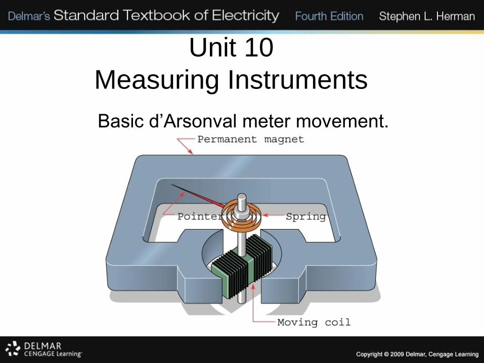
Basic d’Arsonval meter movement.
Unit 10
Measuring Instruments

Basic d’Arsonval meter movement with rectifier to change AC voltage to DC voltage.
Unit 10
Measuring Instruments
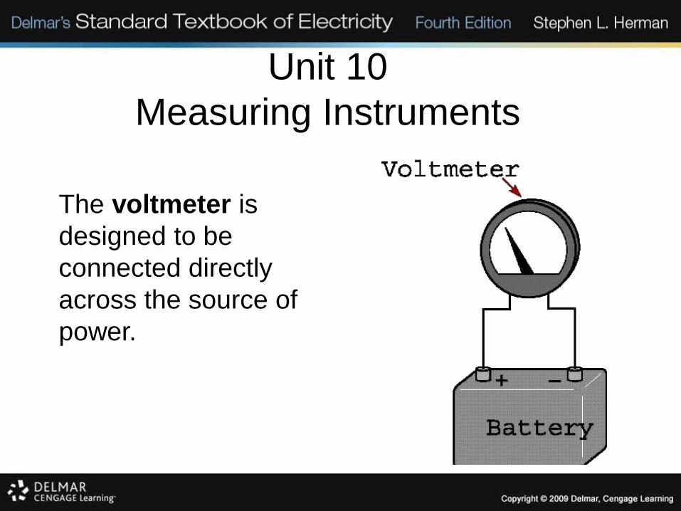
The voltmeter is
designed to be
connected directly
across the source of
power.
Unit 10
Measuring Instruments
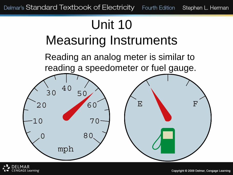
Reading an analog meter is similar to
reading a speedometer or fuel gauge.
Unit 10
Measuring Instruments

The ammeter is used to measure current and
must be connected in series with the load to
permit the load to limit the current flow.
Unit 10
Measuring Instruments

Unit 10
Measuring Instruments
A shunt is used to set the value of the ammeter.
Unit 10
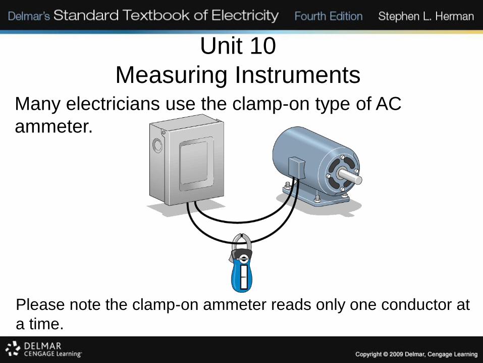
Measuring InstrumentsMany electricians use the clamp-on type of AC
ammeter.
Please note the clamp-on ammeter reads only one conductor at
a time.
Unit 10
Measuring Instruments
Ohmmeters
• The ohmmeter is used to measure
resistance.
• There are two basic types: analog or digital.
• The common VOM (volt-ohm-milliammeter)
contains an ohmmeter.
• An ohmmeter should always be readjusted
to zero when the scale is changed.
Unit 10
Measuring Instruments
Digital Ohmmeters
• Digital ohmmeters display the resistance in
figures instead of using a meter movement.
• They operate by measuring the voltage drop
across a resistor.
• The ohmmeter, whether digital or analog,
must never be connected to a circuit when
the power is turned on!
Unit 10
Measuring Instruments
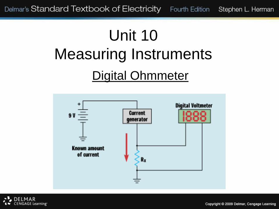
Digital Ohmmeter

Unit 10
Measuring Instruments
Digital Voltmeter
Unit 10
Measuring Instruments
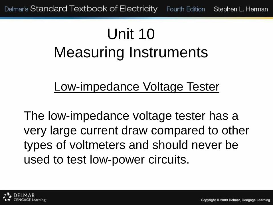
Low-impedance Voltage Tester
The low-impedance voltage tester has a
very large current draw compared to other
types of voltmeters and should never be
used to test low-power circuits.

Unit 10
Measuring Instruments
Low-impedance Voltage Tester
This tester has an impedance of 5000 Ω and
can generally be used to measure voltages
as high as 600 V.

Unit 10
Measuring Instruments
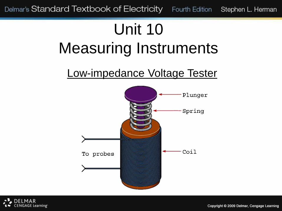
Low-impedance Voltage Tester
This is also known as a solenoid type tester.
This tester is not susceptible to giving the
misleading voltage readings caused by high-
impedance ground paths or feedback
voltages.
Unit 10
Measuring Instruments
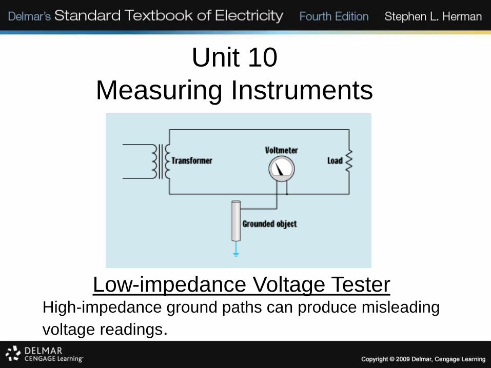
Low-impedance Voltage TesterHigh-impedance ground paths can produce misleading
voltage readings.
Unit 10
Measuring Instruments
Low-impedance Voltage Tester
Unit 10
Measuring Instruments
Reading a Digital Meter
Many digital meters are auto-ranging, which
means that they select the range scale
automatically. This type will display a
notation beside the numerical digits to
indicate the meter scale.

Unit 10
Measuring Instruments
Review:
1. The d’Arsonval movement is one of the
common types of meters.
2. The d’Arsonval movement operates only on
DC currents or rectified AC current.
3. Voltmeters have a high resistance and are
designed to be connected directly across
the power line.
Unit 10
Measuring Instruments
Review:
4. Ammeters have a low resistance and must
be connected in series with a load.
5. Shunts are used to change the value of DC
ammeters.
6. Clamp-on ammeters read only one
conductor at a time.
Unit 10
Measuring Instruments
Review:
7. Ohmmeters are used to measure the
resistance in a circuit.
8. There are two basic types of
Ohmmeters: analog and digital.
9. Ohmmeters must never be connected to
a circuit that has power applied to it.
Unit 10
Measuring Instruments
Review:
10. Digital multimeters display their value in
digits instead of using a meter movement.
11. Digital ohmmeters measure resistance by
measuring the voltage drop across an
unknown resistor when a known amount of
current flows through it.
Unit 10
Measuring Instruments
Review:
12. Low-impedance voltage testers (solenoid
type) are not susceptible to indicating a
negligible voltage caused by a high-
impedance ground or feedback.


