20
TECHNICAL BULLETIN UNIVAC 1107 PUNCHED-CARD SUBSYSTEM March, 1962
TECHNICAL BULLETIN
UNIVAC 1107
PUNCHED-CARD SUBSYSTEM
March, 1962
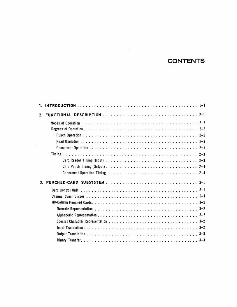
CONTENTS
1. INTRODUCTION ............ ............................... 1-1
2. FUNCTIONAL DESCRIPTION . ................................. 2-1
Modes of Operation. • • • • • • • • • • • • • • • • • • • • • • • • • • • • • • • • • • • • • • • • • 2-2
Degrees of Operation ~ • .• • • • • • • • • • • • • • • • • • • • • • • • • • • • • • • • • • • • • •• 2-2
Punch Operation • • • • • • • • • • • • • • • • • • • • • • • • • • • • • • • • • • • • • • • •• 2-2
.Read Operation. • • • • • • • • • • • • • • • • • • • • • • • • • • • • • • • • • • • • • • • • • 2-3
Concurrent Operation. • • • • • • • • • • • • • • • • • • . • • • • • • • • • • • • • • • • • • • 2-3
Timing ••••••••••••••••••••• ~ • • • • • • • • • • • • • • • • • • • • • • • • • • 2-3
Card Reader Timi ng (Input) • • • • • • • • • • • • • • • • • • • • • • • • • • • • • • • • • 2-3
Card Punch Timing (Output). • • • • • • • • • • • • • • • • • • • • • • • • • • • • • • •• 2-4 Concurrent Operation Timing •••••••••••••••••••••••••••••••• '. 2-4
3. PUNCHED·CARD SUBSySTEM ........ ......................... 3-1
Card Control Unit ........................................... 3-1
Channel Synchronizer •••••••••••••••••••••••••••••••••••••••• 3-1
aO-Column Punched Cards •••••••••••••••••••••••••••••••••••••• 3-2
Numeric Representation • • • • • • • • • • • • • • • • • •. • • • • • • • • • • • • • • • • • • • 3-2
A Iphabetic Representation. • • • • • • • • • • • • • • • • • • • • • • • • • • • • • • • • • • • 3-2
Specia I Character Representation • • • • • • • • • • • • • • • • • • • • • • • • • • • • • • • • 3-2
Input Translation ••••••••••••••••••••••••••••••••••••••••• 3-2
Output Translation. _ ....................................... 3-3
Binary Transfer •••••••••••••••••••••••••••••••••••••••••• 3-3

Programming Features •••.••.••••••••••••••• _ ••••••••••••••••• 3-4
Word Arrangement •• • • • • • • • • • • • • • • • • • • • • • • • • • • • • • • • • • • • • • • 3-5
Function Word • • • • • • • • • • • • • • • • • • • • • • • • • • • • • • • • • • • • • • • • 3-5
Data Word. • • • • • • • • • • • • • • • • • • • • • • • • • • • • • • • • • • • • • • • • • • 3'-5
Status Word •••••••••••••••••••••••••••••••••••••••••• 3-5
Function Repertoire •••••••••••••••••••••••••••••••••.•••••• 3-5
Errors. • • • • • • • • • • • • • • • • • • • • • • • • • • • • • • • • • • • • • • • • • • • • • • 3-6
Read-Check or Punch-Check Verification •••••••••••••••••••••••••• 3-6
Illegal Character Code •••••••••••••••••••••••••••••••••••• 3-6
Interlock Fau It •.....•...•....•...........•....•....•.• 3-6
Se lect Read-Stacker Recei ved Late ••••••.•••••••••••••••••••••• 3-6
Normal Interrupt ••••••••••••••••••••••••••••••••••••••• 3-6
Illegal or Inappropriate Function Code ••••••••••••••••••••••••••• 3-6
Table 1. Punched-Card Subsystem Instructions ••••••••••••••••••••••• 3-7
Table 2. 80-Column Card Code to Field Data Code ••••••••••••••••••••• 3-11

1. INTRODUCTION
Figure 1-1. UNIVAC 1107 Punched-Card Subsystem - Card Reader
Card Punch Unit, and Card Control Cabinet
The Punched-Card Subsystem (Figure 1-1), consisting of Card Reader, Card Punch Unit, Channel Synchronizer, and Card Control Unit, is an integral part of the UNIVAC@ 1107 Thin-Film Memory Computer. Working together with the Central Computer, the Printer, and data storage units, it can operate as an input device, output device, or a concurrent input-output device to form a completely on-line data-processing system.
The Punched-Card Subsystem is designed with the versatility of being adaptable to both 80- or 90-column cards. However, for the present and for the purposes of this technical bulletin, only the 80-column card will be discussed.
Operating as an input device, the Card Reader can read and check 80-column prepunched cards at speeds up to 600 cards per minute.
Operating as an output device, the Card Punch Unit can punch and check 80-column cards at speeds up to 150 cards per minute.
Some of the outstanding features of the PunchedCard Subsystem are:
• Three types of program-controlled translation - card code, row binary, and column binary.
• Arbitrary selection of computer code.
• Bit-by-bit verification of all data read and punched.
• Stacker selection.
• Flexibi Iity in choice of hardware.
1-1

2. FUNCTIONAL DESCRIPTION
The Card Reader consists of an input magazine, a first read station (sensing station 1), a read-verify station (sensing station 2), and three ou tpu t card stackers (Figure 2-1). When the Card Reader is activated, the electro-mechanical system, which
'-1 --------, TO COMPUTER
COMPARE DATA
INPUT MAGAZINE I
I READ R~AD = STATION STATION
~ Q Q -- •••••••• ~ •••• ~ •••• --.. ~-1111111 ..... -""
~~~I 2 o OUTPUT STACKERS
Figure 2·1. Card Reader Transport System
moves a card through the unit, is started. However, no card is sent through the unit until an instruction actuates the picker knife which pushes one card from .the inpu t bin in to the roller mechanism. Once the card is started through the roller mechanism, it is automatically read at sensing station 1 and then verified at sensing station 2. The card, when verified, is transferred to a designated output stacker.
The Card Punch Unit consists of an input magazine, a punching station, a waiting station, and a punch-verify station (read station 3). Refer to Figure 2-2 for a functional layout of the Card Punch Unit. When the Card Punch Unit is activated, it starts the electro-mechanical system which moves a card through the unit. No card is sent through the machine, however, until the feed trip instruction is received from the Card Control
2-2
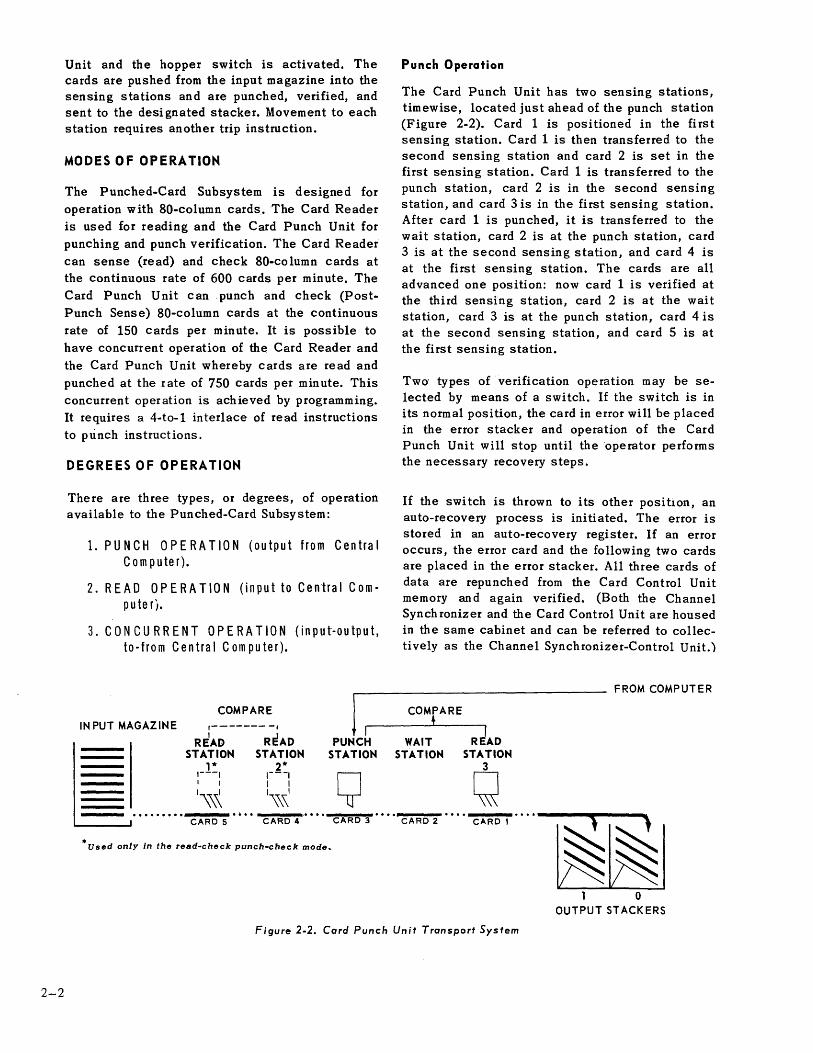
Unit and the hopper switch is activated. The cards are pushed from the input magazine into the sensing stations and are punched, verified, and sent to the designated stacker. Movement to each station requires another trip instruction.
MODES OF OPERATION
The Punched-Card Subsystem is designed for operation with 80-column cards. The Card Reader is used for reading and the Card Punch Unit for punching and punch verification. The Card Reader can sense (read) and check 80-column cards at the continuous rate of 600 cards per minute. The Card Punch Unit can .punch and check (PostPunch Sense) SO-column cards at the continuous rate of 150 cards per minute. It is possible to have concurrent operation of the Card Reader and the Card Punch Unit whereby cards are read and punched at the rate of 750 cards per minute. This concurrent operation is achieved by programming. It requires a 4-to-1 interlace of read instructions to punch instructions.
DEGREES OF OPERATION
There are three types, or degrees, of operation available to the Punched-Card Subsystem:
1. PUNCH OPERATION (output from Central Computer).
2. READ OPERATION (input to Cen"tral ComputerJ.
3. CONCURRENT OPERATION (input-output, to-from Central Computer).
COMPARE
IN PUT MAGAZINE ,------- -, L 1 R~AD READ PUNCH STATION STATION STATION
1* 2* 1---1 1---1
Y , 1 1 1
1\\\ 1\\,\1 .........
CARD 5 CARD 4 CARD 3
• Used only in the read-check punch-check mode~
Punch Operation
The Card Punch Unit has two sensing stations, timewise, located just ahead of the punch station (Figure 2-2). Card 1 is positioned in the first sensing station. Card 1 is then transferred to the second sensing station and card 2 is set in the first sensing station. Card 1 is transferred to the punch station, card 2 is in the second sensing station, and card 3 is in the first sensing station. After card 1 is punched, it is transferred to the wait station, card 2 is at the punch station, card 3 is at the second sensing station, and card 4 is at the first sensing station. The cards are all advanced one position: now card 1 is verified at the third sensing station, card 2 is at the wait station, card 3 is at the punch station, card 4 is at the second sensing station, and card 5 is at the first sensing station.
Two· types of verification operation may be selected by means of a switch. If the switch is in its normal position, the card in error will be placed in the error stacker and operation of the Card Punch Unit will stop until the ·operator performs the necessary recovery steps.
If the switch is thrown to its other position, an auto-recovery process is initiated. The error is stored in an auto-recovery register. If an error occurs, the error card and the following two cards are placed in the error stacker. All three cards of data are repunched from the Card Control Unit memory and again verified. (Both the Channel Synch ronizer and the Card Control Unit are housed in the same cabinet and can be referred to collectively as the Channel Synchronizer-Control Unit.)
COMPARE i
WAIT STATION
CARD 2
I READ
STATION 3 q
CARD 1
FROM COMPUTER
o OUTPUT STACKERS
Figure 2-2. Card Punch Unit Transport System

If the error is not detected during the second pass, the program continues. If the error does occur, the Card Punch Unit will stop and the operator must take the necessary steps to resume operation.
If th e unit runs out of cards, an Interlock Fault is generated. The operation will be continued when more cards are placed in the input magazine and the RESUME Switch is depressed.
Read Operation
Cards are automatically read by the Card Reader and the data stored in the Card Control Unit memory. This data is sent, upon request, to the Central Computer. Cards are inserted 12 edge first, face down.
Upon receipt of the proper input functions, cards are moved from the input magazine into the card channel (Figure 2-1). As it leaves the magazine, card 1 passe~ through the first read station where it is sensed and stored in memory .in card image format. When the complete card has been stored and if a binary by-column (function codes 63 or 73) or by-row (function codes 64 or 74) conditioning instruction has not been given, a translate mode is automatically requested. In this mode, the card image characters are retained in the proper memory location while their computer code translation is stored in what is called an input memory block.
As card 1 moves into the second station, card 2 moves into the first station. At this time, two operations occur simultaneously. Card 2 is sensed and stored in memory while card 1 is verified on a bit-by-bit basis. At the completion of the sense and check operation, card 1 becomes available to the Central Computer and card 2 is automatically translated. All verified cards will go into either the normal stacker or one of the program-selected stackers. Error cards will automatically be placed in the error stacker.
Concurrent Operation
This type of operation permits the reading and punching of 80-column cards at the continuous rate of 750 cards per minute. During the operation, cards are read and punched concurrently. The Channel-Synchronizer-Control Unit can handle the reading of four cards and the punching of one card. However, data is not sent to, and received from, the Central Computer simultaneously.
While data is being read from a card and stored in the Channel Synchronizer-Control Unit memory, the Central Computer is sending data to the Channel Synchronizer-Control Unit memory for punching.
While data is being punched into a card, the Card Reader is reading and storing data in the Channel Synchronizer-Control Unit memory and transferring stored data from the memory to the Central Computer.
To achieve maximum concurrent operation, a 4-to-1 interlace must be maintained through programming (reading of four cards to the punching of one card).
A memory priority register contained in the Card Control Unit is used to direct reading or punching, or to determine if reading or punching is occurring. Data is read at the rate of 600 cards per minute and punched at the rate of 150 cards per minute. The normal procedures for reading and punching are still adhered to.
TIMING
CARD READER TIMING (INPUT)
The Card Reader, under normal operating conditions, can read a card in 100 milliseconds (Figure 2-3). To initiate a read operation, the Card Reader must be active and the Central Computer must send an External Function (EF) Word signifying an input operation to the Card Reader. The EF Word will automatically start the cards through the Card Reader.
For detailed discussion of External Function Words, refer to the Input-Output Instructions manual.
The sensing and storing of the data requires 82.4 milliseconds. The remaining 17.6 milliseconds is used as dead time to insure that the card is completely sensed and its contents translated and transferred to the input block of the Card Control Unit memory.
A Stacker Select instruction must be sent to the Card Reader within 100 milliseconds after the Input Request for that card has been generated.
2-3

2-4
TIMING CHARTS
CARD READING
CARD PUNCHING
265.9ms TRANSLATION TIME
lOOMS
400ms
134.1ms PUNCHING TIME
Figure 2-3. Timing Charts
The operation is stopped if the contents of three cards have been stored in the Card Control Unit memory and none has been transferred to the Central Computer. When a card's contents are transferred to the Central Computer, the operation will continue automatically.
CARD PUNCH TIMING (OUTPUT)
The Card Punch Unit, under normal operating conditions, can punch a card in 400 milliseconds (Figure 2-3). To initiate a punch operation, the Card Punch Unit must be activated and the Central Compu ter must send an External Function (EF) Word signifying an output operation to the Card Punch Unit. When the Run Switch is depressed, three cards are automatically sent into the Card Punch Unit so that upon detection of the EF Word there is a card at the punch station ready to be punched.
The first 265.9 milliseconds are used to translate from computer code and to transfer and set up the data that will be punched into the card. The remaining 134.1 milliseconds are used to punch the data into the card.
During the first 265.9 milliseconds, the Card Punch Unit must receive a new EF (signifying ou tpu t). Word in order to get the next card to be punched, translated, and transferred. If an EF Word is not detected during this time, the operation is stopped after the present card has been transferred.
The next card is delayed until the EF Word is detected and the translation and transfer of -computer code to card code is accomplished for this card. The operation is started again and cards are punched automatically.
CONCURRENT OPERATION TIMJNG
Under normal operating conditions, a card can be read in 100 milliseconds upon receipt of an EF (signifying input) Word or a card can be punched in 400 milliseconds upon receipt of an EF (signifying output) Word. Thus it is possible to read four cards while one card is punched.
The allotted times for card transfer, translation, storage, and setup for reading or punching are the same as the times mentioned above.
If the contents of three cards are stored in the Channel Synchronizer-Control Unit memory, reading stops but punching continues. If the EF (signifying output) Word is not detected in time, the punch operation will stop, but the read operation will continue.
If either unit is given a Function Word with Interrupt, the other unit cannot receive an External Function Word until the unit that received the Function Word with Interrupt has completed its data transfer and sent an Interrupt to the Central Computer.
3.
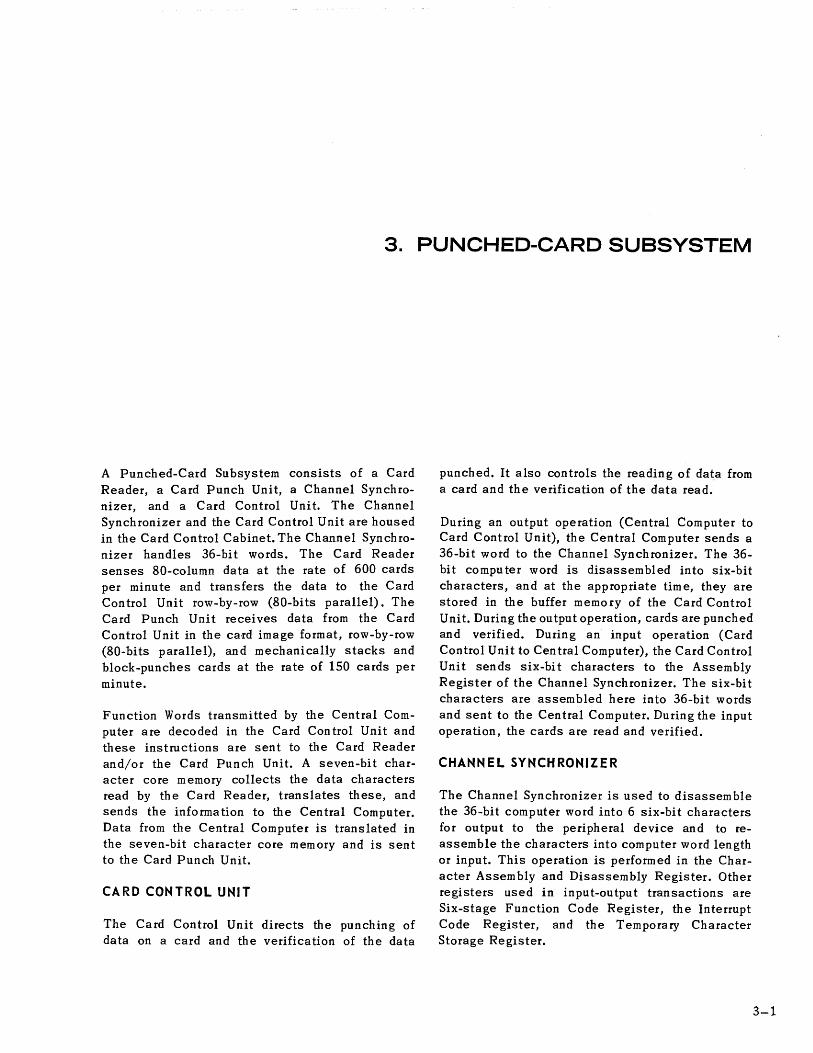
A Punched-Card Subsystem consists of a Card Reader, a Card Punch Unit, a Channel Synchronizer, and a Card Control Unit. The Channel Synchronizer and the Card Control Unit are housed in the Card Control Cabinet. The Channel Synchronizer handles 36-bit words. The Card Reader senses 80-column data at the rate of 600 cards per minute and transfers the data to the Card Control Unit row-by-row (80-bits parallel). The Card Punch Unit receives data from the Card Control Unit in the ca·rd image format, row-by-row (80-bits parallel), and mechanically stacks and block-punches cards at the rate of 150 cards per minute.
Function Words transmitted by the Central Computer are decoded in the Card Con trol Unit and these instructions are sent to the Card Reader and/or the Card Punch Unit. A seven-bit character core memory collects the data characters read by the Card Reader, translates these, and sends the information to the Central Computer. Data from the Central Computer is translated in the seven-bit character core memory and is sent to the Card Punch Unit.
CARD CONTROL UNIT
The Card Control Unit directs the punching of data on a card and the verification of the data
PUNCHE~CARDSUBSYSTEM
punched. It also controls the reading of data from a card and the verification of the data read.
During an output operation (Central Computer to Card Control Unit), the Central Computer sends a 36-bit word to the Channel Synchronizer. The 36-bit computer word is disassembled into six-bit characters, and at the appropriate time, they are stored in the buffer memory of the Card Control Unit. During the output operation, cards are punched and verified. During an input operation (Card Control Unit to Central Computer), the Card Control Unit sends six-bit characters to the Assembly Register of the Channel Synchronizer. The six-bit characters are assembled here into 36-bit words and sent to the Central Computer. During the input operation, the cards are read and verified.
CHANNEL SYNCHRONIZER
The Channel Synchronizer is used to disassem ble the 36-bit computer word into 6 six-bit characters for output to the peripheral device and to reassemble the characters into computer word length or input. This operation is performed in the Character Assembly and Disassembly Register. Other registers used in input-output transactions are Six-stage Function Code Register, the Interrupt Code Register, and the Temporary Character Storage Register.
3-1

3-2
y (12)
x (111
o 0 0 0 0 0 0 0 0 0 0 0 0 0 0 0 0 0 0 0 0 0 0 0 0 0 0 0 0 0 0 0 0 0 0 0 0 0 0 0 0 0 0 0 0 00 0 0 0 0 0 0 0 0 0 0 0 0 0 0 0 00 00000 0 0 0 0 0 0 0 0000 0 1 23451'11~"U~~~~naa~~n~~~~V33.V»D~~.n •• ~~~~"~.~ •• ~~UPM~M~M •• ~aaM •• " •• Mnnn~~.n •••
11111111111111111111111111111111111111111111111111111111111111111111111111111111
2
3
2 2 2 2 2 2 2 2 2 2 2 2 2 22 2 2 2 2 2 2 2 2 2 2 2 2 2 2 2 2 2 2 2 2 2 2 2 2 2 2 2 2 2 2 2 2 2 2 2 2 2 2 2 2 2 2 2 2 2 2 2 2 2 2 2 2 2 2 2 2 2 2 2 2 2 2 2 2 2
33333333333333333333333333333333333333333333333333333333333333333333333333333333
4 ~ 44444444444444444444444444444444444444444444444444444444444444444444444444444444
5
0:: z ~ 55555555555555555555555555555555555555555555555555555555555555555555555555555555
6
7
~ &&&66666&66&66&66666666666666666666666666666666666666666666666666666666666666666
~ 1177 7 17 17 7 117 7 7 7 7 77 7 17 77 7 7 77 7 7 7 7 77 7 7 7 77 7 7 7 7 7 7 7 7 77 1 71 77 1 77 7777 7 77 77 71 7 77 77 77 7 77 77 :::i
8 8 8 8 B 8 8 8 8 8 8 8 8 8 8 88 8 8 8 8 8 8 8 8 8 8 8 8 8 8 8 8 8 8 8 8 8 8 8 8 8 8 8 8 8 8 8 8 8 8 8 8 8 8 8 8 8 8 8 8 8 8 8 8 8 8 8 8 8 8 8 8 8 8 8 8 8 8 8 8
9 ~ 99999999999999999999999999999999999999999999999999999999999999999999999999999999 12345ill'~"UU"u~naam~n~N~3V3~.~»D~~.n •• ~~~Q~~.~ .• ~~UPM~M~~M.~aUM.~ •• Mnnn~~.n •••
Figure 3·1. The aO·Co/umn Carel
SO·COLUMN PUNCHED CARDS
Data cards entering the Punched-Card Subsystem normally contain information recorded in 12-bit card code. Alphabetic and numeric information is punched in 80-column cards in the form of holes. Each card (Figure 3-1) contains 960 possible punching positions (80-columns with 12 punching positions in each column). No more than 240 holes should be punched in a card at only one time, otherwise an interlock fault will result. The punching positions in each column are numbered from top to bottom Y(12), X(11), 0, and 1 through 9. Positions Y(12), X(11), 0, and 8 are reserved for zone bits; positions 1, 2, 3, 4, 5, 6, 7, and 9 are reserved for numeric bits.
Numeric Representation
Numeric digits are represented by a single punch in the proper digit position. The X(11) and Y(12) positions are not used for numeric punching.
Alphabetic Representation
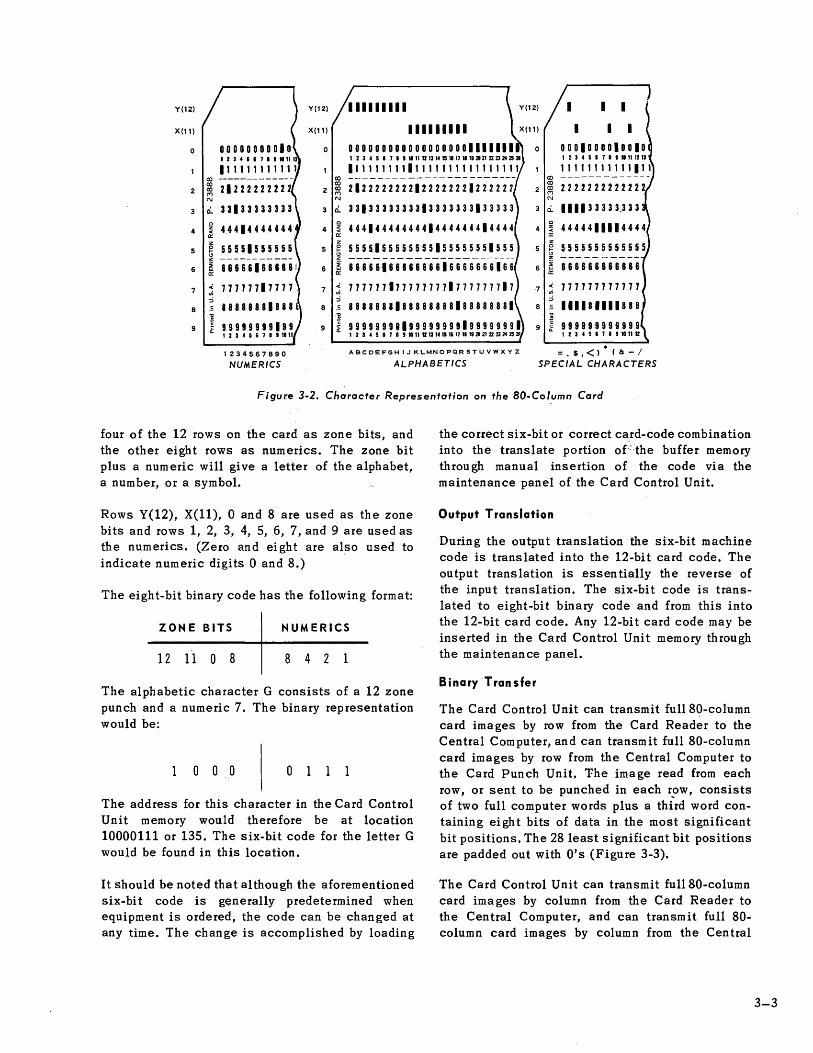
Alphabetic characters are represented by a combination of two punches, a zone punch and a numeric punch (Figure 3-2). The letters A through I are represented by a combination of a Y(12) zone punch plus the digit punch 1 through 9. The letter A is a combination Y(12) and 1. The letter B is a combination Y(12) and 2, and so on.
The letters J through R are represented by a combination of an X(11) zone punch plus the digit punch 1 through 9. The letter J is a combination of X(11) and 1. The letter K is a combination of X(11) and 2, and so on.
The letters S through Z are represented by a combination of a 0 zone punch plus the digit punch 2 through 9. The letter S is a combination of 0 and 2. The letter T is acorn bination of 0 and 3, and so on.
Special Character Representation
Special characters are repre,sented by various combinations of single and multiple punches (Figure 3-2). Most special characters are composed of three punches, one of which is an 8.
Input Translation
During the input-translation the 12-bit card code is translated into a six-bit machine code. The 12-bit code is first translated into an eight-bit binary code, which in tum locates an address in the Card Control Unit memory. From this address the six-bit code is obtained and sent to the Central Computer. Any six-bit code may be inserted in the memory through the Card Control Unit maintenance panel.
The translation of the 12-bit card code to the ei gh t-bit binary code is accomplished by using
Y(12) Y(12) 111111111
X(11) X(11)
o 0 12345171 •• 1112
111111111111 co -------------
2 ~ 21222222222 2 N
3 0.. c
4 ':i a: z
5 ~ __________ _
6 ~
c 4 ':i
a: z
5 ~
6 ~
111111111 0000000000000000001111111 12345'711.11UUM"WnWWaVnD~~a
11111111111111111111111111 ----- ----------- -------2122222222122222221222221
3313333333313333333133333
4441444444441444444414444
5555155555555155555551555
8666616686668616666666166
I I I
I 0001000010010 I 2 3 4 5 • 7 1 • 11111213
lI1fl1111111" CO --------- ----CO 2222222222222 2 CO <"'l N
3 0.. 1111 3 3 3 3 3,3 3 3 c
4444411114444 4 z "" a: z
5555555555555 -5 0 f-
" z --- -- -----6 ~
a: 866666666868
7 .( en ::i
7 ~ 7777771777777771777777717 ::i
8 ~ 8888888188888888188888881
7 .( 777777777777 en ::i
111181111888 8 c 8 --
1 9999999819999999919999999. 9 j 999999999999 1234517".l1UUM"HnWW~~nD~~~ 1234587"101112
1234567890
NUMERICS
ABCDEFGHIJKL.MNOPQRSTUVWXYZ =. $.<). (8: - /
ALPHABETICS SPECIAL CHARACTERS
Figure 3-2. Character Representation on the aO-Col,umn Card
four of the 12 rows on the card as zone bits, and the other eight rows as numerics. The zone bit plus a numeric will give a letter of the alphabet, a number, or a symbol.
Rows Y(12), X(II), 0 and 8 are used as the zone bits and rows 1, 2, 3, 4, 5,6, 7, and 9 are used as the numerics. (Zero and eight are also used to indicate numeric digits 0 and 8.)
The eight-bit binary code has the following format:
ZONE BITS NUMERICS
12 11 0 8 8 4 2 1
The alphabetic character G consists of a 12 zone punch and a numeric 7. The binary representation would be:
o 0 0 0
The address for this character in the Card Control Unit memory would therefore be at location 10000111 or 135. The six-bit code for the letter G
would be found in this location.
It should be noted that although the aforementioned six-bi t code is generally predetermined when equipment is ordered, the code can be changed at any time. The change is accomplished by loading
the correct six-bit or correct card-code combination into the translate portion of=the buffer memory through manual insertion of the code via the maintenance panel of the Card Control Unit.
Output Translation
During the output translation the six-bit machine code is translated into the 12-bit card code. The output translation is essentially the reverse of the input translation. The six-bit code is translated to eight-bit binary code and from this into the 12-bit card code. Any 12-bit card code may be inserted in the Card Control Unit memory through the maintenance panel.
B inaryTran sfer
The Card Control Unit can transmit fu1180-column card ima ges by row from the Card Reader to the Central Computer, and can transmit full 80-column card images by row from the Central Computer to the Card Punch Unit. 'Fhe image read from each row, or sent to be punched in each r:>w, consists of two full computer words plus a third word containing eight bits of data in the most significant bit positions. The 28 least significant bit positions are padded out with O's (Figure 3-3).
The Card Control Unit can transmit fu1180-column card images by column from the Card Reader to the Central Computer, and can transmit full 80-column card images by column from the Central
3-3

1 0 1 1 0 0 1 0 1 1 1 1 0 0 1 0 0 1 0 0 0 1 0 1 0 11 0 0 1 0 1 0 0 0 Ii WORD 7
0000001111010000000111100,10000001010 WORDS
, 0 0 0 0 0 0 0 1 X X X X X X X X X X X X X X X X X X X X X X X X X X X X WORD 9
10110010111100100100010101100101000100000111101000000011110010000001011000000001 '2J4S'7 ••• "nnUR.".~.nnDN~.V.3.~»»K~.m ••• ~Q~"~.U •• ~~UDM~.~ ••• ~uaM •• ~ •• ~nn~H~Mn~~. """"""'1'1'1"'11"'111111""1"1'11'1'1"1'1"1111111111111111111111111111
~22222222222222222222222222222222222~22222222222222222222222222222222222~2222222 333 33 33 3333 33 3 3 33333333 3 3 3333333333313333333333333 3 3 3 3 3 3 3 3 3 3 3 3 3 3 3 3 3 3 3 3 3 3 3133 3 33333
~ 4444444444444444444444444444444444441444444444444444444444444444444444444~4444444
I 5555555555555555555555555555S5555555~55555555555555515555555555555555555~5555555 j 8'8&&88'8'8~88866&"66666666666666G616666666666666666666666666"6666'6'66~6666666 : 77 77 77 77 77 77 77 77 7 77 7 77 77 77 71 7 7 7 7 7 7 77h 7 7 77 7 77 7 7 7 77 7 7 7 7 7 7 7 77 7 7 77 77 7 11 77 111177 1 7 7 77 7
j "8888888188888888888888888888888888~8888B888888888888888888888888888888~8888888 J II II II 9911 19 9999999 999 9 9 9 9 9 9 9 9 9 9 9 9 9 919 9 9 9 9 9 9 9 9 9 9 9 9 999 9 9 9 9 9 9 9 9 9 9 9 9 9 9 9 9 99 9919 9 9 9 U 9 9
'2J41'7.t."UDUqUnqq.nnDN~.V.3.~»»K~.n ••• ~ca"~.U ••• ~UDM~.n ••• ~uaM •• p •• Mnn~HMMn~~.
Figure 3-3. Relationship of Computer Words to Card Punches (by Row)
Computer to the Card Punch Unit. The image read from each card, or sent to be punched in each card, consists of 26 full words of data plus a word containing 24 bits of data in the most significant bit positions. The 12 least significant bit positions are padded out with O's (Figure 3-4).
When the Card Control Unit is conditioned for either of the two types of binary output, it is possible for the Central Computer to send it output data which calls for punching up to 960 holes in a single card. However, an attempt to punch more than 240 holes per card causes the Card Punch Unit to interlock. The Central Computer is advised of this condition by means of a Status Word and an External Interrupt signal.
PROGRAMMING FEATURES
Any part of the Central Computer's internal core storage can be used as an input-output data buffer storage area, with the exception of the few special core storage locations that are reserved for the Incremental Clock and the Interrupt Words. Information is transferred between the Computer and the Punched-Card Subsystem in "blocks" of data.
A block is made up of 14, 27, or 36 computer words depending on the type of translation. Words in a block must occupy consecutive core memory addresses, starting with a program-determined first word address and ending with a programdetermined last word address.
An input-output data transfer, which occurs independently of main program control, is used to pass data between core storage and the PunchedCard Subsystem. Before execution of a transfer of data, the program must perform the following steps:
1. Activate the channel to be used and send the proper Function Word or words to the Punched-Card Subsystem.
2. Activate the channel to be used for the information transfer and indicate the starting address for the transfer.
Step 2 is accomplished with one of the inputoutput instructions; 75 (j = 00), 75 (j = 01), 75 (j = 04), or 75 (j = 05). Step 1 above is performed by either a 75 U = 10) or 75 (j = 11) instruction. The Punched-Card Subsystem is now

1001000000000100000000010010001000001 WORDl
100100000000010000000001000000000000 I WORD2
{--I ! II I I
100100000000000000000000000000100000000000000000000000000000000000000000000000000 1234561"~"UUU~~nUUM~nn~~Nn3aM~~D~~.n ••• ~GQ"~.~q.~~~~~~~~~".~aPMe.~ •• NnnnHn~nn~. 111 ,11111111111111111111111111111111111111111111111111111111111111111111111111111
~ 222122 2222222222 22222222222222222222222 2 2 2 2 2 2 2 2 2 2 22222222222222222 2 2 2 2 2 2 2 2 2 2 2 2 2 2 2
c:i.. 3 33133 3333333333 3 3 3 3 3 3 3 3 3 3 3 3 3 3 3 3 3 3 3 3 3 3 3 3 3 3 3 3 3 3 3 3 3 3 3 3 333 3 3 3 3 3 3 3 3 3 3 3 3 3 3 3 3 3 3 3 3 3 33333
: 441144444444444444444444444444444444444444444444444444444444444444444444444444444
~ 55555555555555555555555555555555555555555555555555555555555555555555555555555555
~ 86666666666666666666666666666666666666666666666666666666666666666666666666666666
~ 777777177777777777777777777777777777777777777777777777777777777777777777777777777
88888888888888888888888888888888888888888888888888888888888888888888888888888888
1 919919199999999999999999999999999999999999999999999999999999999999999999999999999 12345'~8'~"UUUU~nuuMnnnN~3naa.n~DM~.D ••• ~Ca" •• u ••• ~R~~".~ ••• ~aPMe.Q •• NnnnHn~nnn.
Figure 3-4. Relationship of Computer Woras to Cara Punches (by Column).
ready to receive data. Once the appropriate input or output instruction is received, data caR. be transferred between the Central Computer storage and the Punched-Card Subsystem without main program intervention.
Word Arrangement
The Punched-Card Subsystem accommodates three types of computer input-output words. They are the Function Word, Data Word, and Status Word.
FUNCTION WORD
The Function Word designates the operation to be performed by the Punched-Card Subsystem. It is arranged in groups of six-bit characters as follows:
FC I FUNCTION WORD
6 5 4 3 2 1
35 30 29 24 23 18 17 12 11 6 5 0
The six most significant bit positions (35 through 30) contain FC (the function code of the Function Word). The function code determines the actual operation to be executed by the Punched-Card Subsystem (read or punch).
DATA WORD
The Data Word (input or output) is arranged in groups of six-bit characters, with bit positions
35 through 30 containing the most significant character (MSC) and bit positions 5 through 0 containing the least significant character (LSC).
M~fit I DATA WORD 1... Lttr.st ~~ni icantl ~~"' Icant aracter I aracter
6 5· 4 3 2 1
35 30 29 24 23 18 17 12 11 6 5 0
STA TUS WORD
The Status Word contains the error information generated by the Card Control Unit; it is arranged in groups of six-bit characters with the status code (s) represented by bit positions. 35 throu§h 30.
I
STATUS SC I WORD
6 5 4 3 2 1
35 30 29 24 23 18 17 12 11 6 5 0
The status code or error code is generated by the Card Control Unit. The upper four bits of the Status Word are commonly referred to as the interrupt code and any error information generated is contained in these upper four bits (positions 35-32).
F unction Repertoire
Operation of the Card Control Unit depends on the type of Function Word handled. Table 1 is a list of the programmed function codes contained in the upper six-bits of the Function Word (FC portion).
3-5
3-6
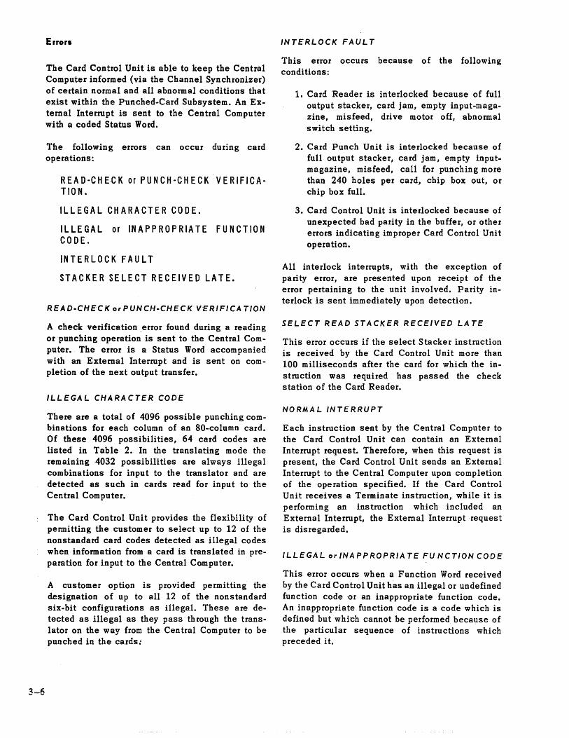
Errors
The Card Control Unit is able to keep the Central Computer informed (via the Channel Synchronizer) of certain normal and all abnormal conditions that exist within the Punched-Card Subsystem. An External Interrupt is sent to the Central Computer with a coded Status Word.
The following errors can occur during card operations:
REAO-CHE-CK or PUNCH-CHECK VERIFICATION.
ILLEGAL CHARACTER CODE.
ILL EGA L or IN A P PRO P R I ATE FUN C T ION CODE.
IN T E R L OC K F A U L T
STACKER SELECT RECEIVED LATE.
READ.CHECK orPUNCH·CHECK VERIFICATION
A check verification.error found during a reading or punching operation is sent to the Central Computer. The error is a Status Word accompanied with an External Interrupt and is sent on completion of the next output transfer.
ILLEGAL CHARACTER CODE
There are a total of 4096 possible punching combinations for each column of an SO-column card. Of these 4096 possibilities, 64 card codes are listed in Table 2. In the translating mode the remaining 4032 possibilities are always illegal combinations for input to the translator and are detected as such in cards read for input to the Central Computer.
The Card Control Unit provides the flexibility of permitting the customer to select up to 12 of the nonstandard card codes detected as illegal codes when information from a card is translated in preparation for .input to the Central Computer.
A customer option is provided permitting the designation of up to all 12 of the nonstandard six-bit configurations as illegal. These are detected as illegal as they pass through the translator on the way from the Central Computer to be punched in the cards:
INTERLOCK FAUL T
This error occurs because of the following conditions:
1. Card Reader is interlocked because of full output stacker, card jam, empty input-magazine, misfeed, drive motor off, abnormal switch setting.
2. Card Punch Unit is interlocked because of full output stacker, card jam, empty inputmagazine, misfeed, call for punching more than 240 holes per card, chip box out, or chip box full.
3. Card Control Unit is interlocked because of unexpected bad parity in the buffer, or other errors indicating improper Card Control Unit operation.
All interlock interrupts, with the exception of parity error, are presented upon receipt of the error pertaining to the unit involved. Parity interlock is sent immediately upon detection.
SELECT READ STACKER RECEIVED LA TE
This error occurs if the select Stacker instruction is received by the Card Control Unit more than 100 milliseconds after the card for which the instruction was required has passed the check station of the Card Reader.
NORMAL INTERRUPT
Each instruction sent by the Central Computer to the Card Control Unit can contain an External Interrupt request. Therefore, when this request is present, the Card Control Unit sends an External Interrupt to the Central Computer upon completion of the operation specified. If the Card Control Unit receives a Terminate instruction, while it is performing an instruction which included an External Interrupt, the External Interrupt ·request is disregarded.
ILLEGAL or INAPPROPRIA TE FU NCTION CODE
This error occurs when a Function Word received by the Card Control Unit has an illegal or undefined function code or an inappropriate function code. An inappropriate function code is a code which is defined but which cannot be performed because of the particular sequence of instructions which preceded it.

TABLE 1. PUNCHED .. CARD SUBSYSTEM INSTRUCTIONS
FUNCTION CODE
OCTAL BINARY
02 000010
03 000011
04 000100
05 000101
06 000110
12 001010
13 001011
14 001100
DESCRIPTION
Output
Punch a card with the data to follow; advance all cards one station and feed a card. Stacker zero is automatically selected when this instruction is given.
Output
Punch a card with the data to follow; select stacker 1 for the card, advance all cards one station and feed a card.
Output
Condition Card Control Unit to translate output data from machine code to card code for the following output transfers. This is the normal output operating mode.
Output
Condition Card Control Unit to receive output data card image by column.
Output
Condition Card Control Unit to re~eive output data card image by row.
Output
Punch a card with the data t9 follow; advance all cards one station and feed a card. When the operation is completed send an External Interrupt to the Central Computer.
Output
Punch a card with the data to follow; select stacker 1 for the card, advance all cards one station and feed a card. When the operation is completed send an External Interrupt to the Central Computer.
Output
Condition the Card Control Unit to translate output data from machine code to card code for the following output transfers. When the operation is completed (function is transferred) send an External Interrupt to the Central Computer.
3-7
3-8
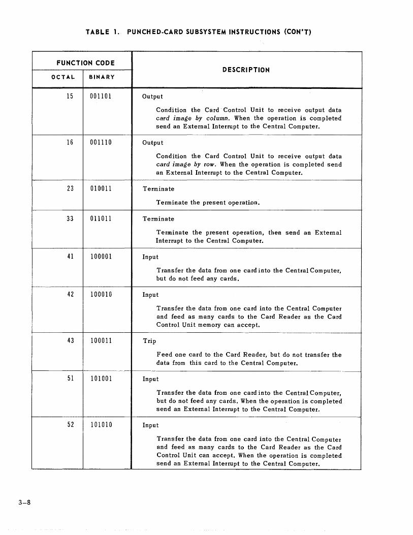
TABLE 1. PUNCHED·CARD SUBSYSTEM INSTRUCTIONS (CON'T)
FUNCTION CODE
OCTAL BINARY
15 001101
16 001110
23 010011
33 011011
41 100001
42 100010
43 100011
51 101001
52 101010
D ESCRI PTION
Output
Condition the Card Control Unit to receive output data card image by column. When the operation is completed send an External Interrupt to the Central Computer.
Output
Condition the Card Control Unit to receive output data card image by row. When the operation is completed send an External Interrupt to the Central Computer.
Terminate
Terminate the present operation.
Terminate
Terminate the present operation, then send an External Interrupt to the Central Computer.
Input
Transfer the data from one card into the Central Computer, but do not feed any cards.
Input
Trip
Transfer the data from one card into the Central Computer and feed as many cards to the Card Reader as the Card Control Unit memory can accept.
Feed one card to the Card Reader, but do not transfer the data from this card to the Central Computer.
Input
Transfer the data from one card into the Central Computer, but do not feed any cards. When the operation is completed send an External Interrupt to the Central Computer.
Input
Transfer the data from one card into the Central Computer and feed as many cards to the Card Reader as the Card Control Unit can accept. When the operation is completed send an External Interrupt to the Central Computer.

TABLE 1. PUNCHED·CARD SUBSYSTEM INSTRUCTIONS (CON'T)
FUNCTION CODE
OCTAL BINARY
53 101011
54 101100
60 110000
61 110001
62 110010
63 110011
70 111000
71 111001
Trip
DESCRIPTION
Feed one card to the Card Reader, but do not transfer the data from this card to the Central Computer. Send an External Interrupt to the Central Computer upon receipt of that Function Word requesting the External Interrupt.
Input
Condition the Card Control Unit to transfer input data card image by row to the Central Computer for the following input transfer instructions.
Select Stacker
Select stacker 1 for the card from which data was most recently read into the Central Computer.
Select Stacker
Select stacker 2 for the card from which data was most recently read into the Central Computer.
Input
Condition the Card Control Unit to translate the input data from card code to machine code for the following input transfers. This is the normal input operating mode.
Input
Condition the Card Control Unit to transfer input data card image by column to the Central Computer for the following input transfer instructions.
Select Stacker
Select stacker 1 for the card from which data was most recently read into the Central Computer, then send an External Interrupt to the Central Computer upon receipt of that Function Word requesting the External Interrupt.
Select Stacker
Select stacker 2 for the card from which data was most recently read into the Central Computer, then send an External Interrupt to the Central Computer upon receipt of of that Function Word requesting the External Interrupt. I
3-9
3-10
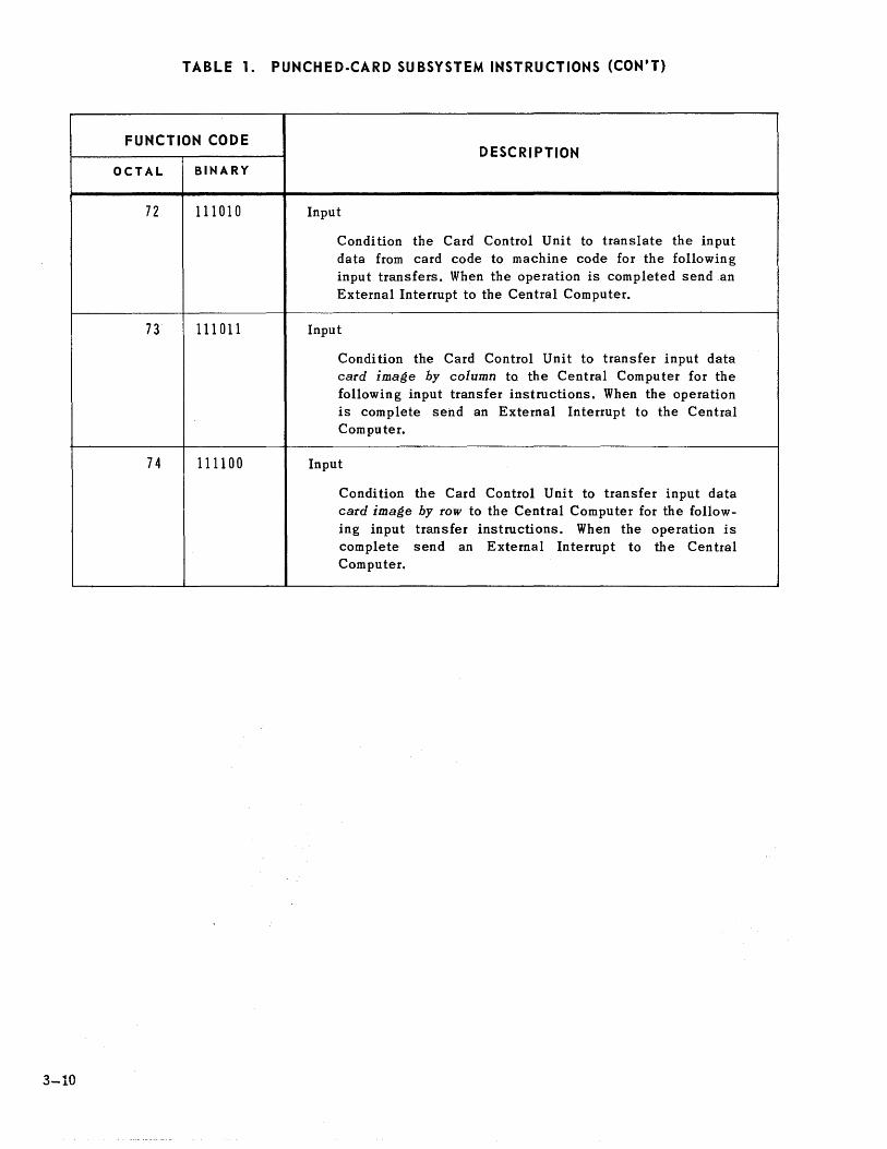
TABLE 1. PUNCHED·CARD SUBSYSTEM INSTRUCTIONS (CON'T)
FUNCTION CODE
OCTAL BINARY
72 111010
73 111011
74 111100
DESCRIPTION
Input
Condition the Card Control Unit to translate the input data from card code to machine code for the following input transfers. When the operation is completed send an External Interrupt to the Central Computer.
Input
Condition the Card Control Unit to transfer input data card image by column to the Central Computer for the following input transfer instructions. When the operation is complete send an External Interrupt to the Central Computer.
Input
Condi tion the Card Control Unit to transfer input data card image by row to the Central Computer for the following input transfer instructions. When the operation is complete send an External Interrupt to the Central Computer.

TABLE 2. SO·COLUMN CARD CODE TO FIELD DATA CODE
80-COLUMN BIT OCTAL 80-COLUMN BIT OCTAL CARD CODE SYMBOL CODE CODE CARD CODE SYMBOL CODE CODE
0 o (zero) 110000 60 0-6 W 011100 34 1 1 110001 61 0-7 X 011101 35 2 2 110010 62 0-8 Y 011110 36 3 3 110011 63 0-9 Z 011111 37 4 4 110100 64 blank (space) 000101 05 5 5 110101 65 12 & 100110 46 6 6 110110 66 11 - 100001 41 7 7 110111 67 0-1 / 111100 74
8 8 111000 70 12-3-8 111101 75 9 9 111001 71 12-4-8 ) 100000 40 12-1 A 000110 06 11-3-8 $ 100111 47 12-2 B 000111 07 11-4-8 * 101000 50 12-3 C 001000 10 0-3-8 , 101110 56 12-4 D 001001 11 0-4-8 ( 101001 51 12-5 E 001010 12 3-8 = 100100 44 12-6 F 001011 13 4-8 < 100011 43
12-7 G 001100 14 12-2-8 + 100010 42 12-8 H 001101 15 11-2-8 101011 53 12-9 I 001110 16 0-2-9 , 111010 72 11-1 J 001111 17 2-8 > 100101 45 11-2 K 010000 20 12-7-8 L.C. 000010 02* 11-3 L 010001 21 11-7-8 ? 101100 54* 11-4 M 010010 22 0-7-8 0 111110 76* 11-5 N 010011 23 7~8 , 111011 73*
11-6 0 010100 24 12-6-8 U.C. 000001 01* 11-7 P 010101 25 11-6-8 u 101010 52* 11-8 Q 010110 26 0-6-8 0 101111 57* 11-9 R 010111 27 6-8 Idle 111111 77* 0-2 S 011000 30 12-0 L.F. 000011 03* 0-3 T 011001 31 11-0 C.R. 000100 04* 0-4 U 011010 32 0-5-8 ! 101101 55* 0-5 V 011011 33 8-9 M.S. 000000 00*
* These are non-standard codes.
3-11

~&u.d.~ DIVISION OF SPERRY RAND CORPORATION


