248
UNIVAC DATA PROCESSING DIVISION MULTI-PROCESSOR SYSTEM EXEC II PROGRAMMERS REFERENCE MANUAL UP-4058
UNIVAC DATA PROCESSING DIVISION
MULTI-PROCESSOR SYSTEM
EXEC II
PROGRAMMERS REFERENCE MANUAL
UP-4058

This manual is published by the Univac Division of Sperry Rand Corporation in loose leaf format as a rapid and complete means of keeping recipients apprised of UNIVAC ® Systems developments. The information presented herein may not reflect the current status of the programming effort. For the current status of the programming, contact your local Univac Representative.
The Univac Division will issue updating packages, utilizing primarily a page-for-page or unit replacement technique. Such issuance will provide notification of hardware and/or software changes and refinements. The Univac Division reserves the right to make such additions, corrections, and/or deletions as in the judgment of the Univac Division are required by the development of its respective Systems.
® REGISTERED TRADEMARK OF THE SPERRY RAND CORPORATION PRINTED IN U.S.A.
01966- SPERRY RAND CORPORATION

UP-4058 UNIVAC 1108 EXEC II Preface SECTION:
PREFACE
In implementing EXEC II on the 1108, compatibility with the 1107 EXEC II system has been maintained. Those hardware features of the 1108 which do not exist on the 1107 are not utilized by EXEC II. The user is warned not to attempt to make use of these new hardware features, since the system does not provide for them.
The above restriction does not apply to the 1108 function code repertoire. Except for those functions reserved by the Executive for its own use, all 1108 function codes may be used. A list of reserved instructions, as well as other restrictions imposed by EXEC II on worker programs, is provided in Section 3 A. of this manual.
i PAGE:

UP-4058 UNIVAC 1108 EXEC II Contents 1 SECTION: PAGE:
CONTENTS
Page
PREFACE i
CONTENTS to 4
1. INTRODUCTION 1 -1 to 1-2
A. HISTORY 1 -1
B. MANUAL ORGANIZATION 1 -1
C. EXEC II MINIMUM CONFIGURATION 1-2
2. SYSTEM LAYOUT AND DEFINITIONS 2-1 to 2-10
A. THE RESIDENT ROUTINES AND THEIR FUNCTIONS 2-1
B. SYSTEM DRUM STRUCTURE 1-4
1. EXEC 2-4 2. Processors and the Processor Scratch Area 2-5 3. Library PCF 2-6 4. Execution Area 2-7 5. User PCF 2-7 6. Symbiont Drum Buffers 2-9
C. WORKER PROGRAM AREAS IN CORE AND DRUM 2-10
3. SYSTEM CONTROLS 3-1 to 3-51
A. EXECUTIVE CONTROL FUNCTIONS 3-1
1. Multiprogram Control 3-2 2. Hardware Control 3-3 3. Interrupt Control 3-6
B. USER CONTROL OF SYSTEM 3-7
1. Job-EXEC Communication 3-7
a. RUN Control Card 3-7 b. ASG Control Card 3-9
2. Job-Operator Communications 3-10
a. MSG Control Card 3-10
3. System I/O Definition 3-11
a. EOF, FIN, and COL Control Cards 3-11 b. TPR and DPR Control Cards 3-12 c. HDG Control Card 3-13
4. Language Processor Controls 3-14
a. 1108 Assembler: ASM and PDP Control Cards 3-14
b. COBOL: COB and CLP Control Cards 3-17 c. FORTRAN: FOR and LFT Control Cards 3-18 d. Source Language Correction 3-19

UP-40S8
3.
UNIVAC 1108 EXEC II
SYSTEM CONTROLS - Continued
5. Allocator Control
a. MAP Processor: MAP Control Cards b. XQT, ABS and SOD Control Cards c. The Allocator
6. User PCF Controls
a. b. c.
Elements and the ELT Control Card Language Processor and Allocator Outputs CUR (Complex Utility Routines)
7. Library Control: LBR Control Card (XQT LIBRY)
8. System Generation: XQT RSDNT
9. Diagnostic Routines: Debug Control
a. ICS: ICS Control Card (XQT ICS) b. PMD Control Card c. Panic Dumps
10. Control Card Errors
a. Invalid Information b. Misplaced Card c. Control Cards
4. WORKER PROGRAMS
A. SPECIAL SYSTEM PACKAGES
1. SORT, LIFT, APT, PERT, etc. 2. Processors
B. USER-DESIGNED PROGRAMS
1. Input-Output Specifications
a. Symbionts and Co-operatives b. Tape and Drum Routines
1) Tape Assignment Routines 2) Tape I/O Package 3) Drum r/o: Normal Mode and
Status Codes 4) Drum I/O: Packet Mode (DPKT$) 5) Block Buffering Package 6) Label and Item Package
Page
3-20
3-20 3-27 3-29
3-34 3-36 3-37
3-42
3-42
3-43
3-43 3-48 3-50
3-50
3-50 3-51 3-51
4-1
4-1
4-1 4-1
4-2
4-2
4-2 4-13
4-14 4-17
4-28 4-35 4-37 4-50
Contents 2 SECTION: PAGE:
to 4-101

UP-4058 UNIVAC 1108 EXEC II
4. WORKER PROGRAM - Continued Page
c. Direct I/O 4-58
1) General Information 4-58 2) Package Requirements 4-59 3) The Segregated Card I/O Package 4-63 4) The Dispatcher Subroutines 4-65
d. Conso le I/O e. Paper Tape I/O Package
2. System Subroutines Other than I/O
a. Editing Routines
1) Resident Editing Routine 2) Clock Editing Routine 3) Generalized Output Editing
Routine: EOUI$ 4) Format Specifications
4-70 4-72
4-74
4-74
4-75 4-76
4-78 4-85
b. Control Routines Other Than Input/Output 4-89
1) Error Interrupts 2) MSEA$ 3) MREA$ 4) MLOAD$ 5) MCHN$
3. Diagnostic Subroutines
C. INITIALIZATION AND TERMINATION
4-89 4-90 4-91 4-91 4-92
4-93
4-101
Contents SECTION: PAGE:
5. JOB SET-UP 5-1 to 5-11
A. RUN DECKS (EXAMPLES) 5-1
1. COBOL Compilation 5-1 2. Reassembly from Magnetic Tape 5-2 3. Compilation from Tape 5-3 4. PCF Table of Contents Listing Run 5-4 5. Execution of Programs on Magnetic Tape 5-6 6. Incorrect Deck 5-7
B. REMOTE OPERATION
1. Operating Instructions 2. Stop Cards
6. DIAGNOSTIC MESSAGES PRODUCED BY THE SYSTEM
A. RESIDENT (EXEC) CONSOLE PRINTOUTS
B. RESIDENT (EXEC) PRINTER MESSAGES
C. CUR PRINTER MESSAGES
D. ALLOCATOR PRINTER MESSAGES
E. MAP PRINTER MESSAGES
F. PMD PRINTER MESSAGES
5-8
5-9 5-11
6-1 to 6-35
6-1 to 6-11
6-12 to 6-17
6-18 to 6-24
6-25 to 6-29
6-30 to 6-33
6-34 to 6-35
3

UP-40S8 UNIVAC 1108 EXEC II
A. MAIN STORAGE LAYOUT
B. SYSTEM DRUM LAYOUT
1. Single-Channel Drum Layout 2. Multi-Channel Drum Layout (To be Supplied)
C. CONTROL CARDS
1. Listing and Function of Control Cards 2. Control Card Options 3. Format of Control Cards 4. Format of Processor Control Cards
D. SPECIAL BLOCK FORMATS
1. Print-Image Blocks
a. Drum Blocks b. Tape Block for Print Images c. Print Image Blocks Written in DLT-5 Format
2. Card-Image Blocks
a. Drum Blocks b. Tape Blocks
3. Paper Tape Images on Magnetic Tape (via symbiont action)
4. Program Elements on Magnetic Tape (via CUR) 5. Block Buffering Package File-Description Table 6. Label and Item Package Formats
a. Format of the File-Description Area b. Format of Label Block c. Format of Bypass Sentinels d. Format of End·-o f- Fi 1 e Sentinel e. Format of End-of-Reel Sentinel f. Format of Fixed-Length Item Data Block g. Format of Variable-Length Item Data Block h. Multifile Reels
F. SYSTEM TABLE LAYOUTS (To Be Supplied)
G. 1107 EXEC II - DIFFERENCES (To Be Supplied)
Contents SECTION:
APPENDIXES
Page
A-1 to A-1
B-1 to B-2
B-1
C-1 to C-10
C-1 C-3 C-7 C-9
D-1 to D-16
D-1
D-1 D-2 D-2
D-3
D-3 D-3
D-3 D-4 0-5 0-11
D-11 D-13 D-14 D-14 D-14 D-15 D-16 D-16
4 PAGE:

UP-40S8 UNIVAC 110B EXEC II 1 SECTION:
1. INTRODUCTION
A. HISTORY
This manual is intended to be a guide for programmers using the EXEC II system on the 1108. Sufficient information has been included to provide the user with fundamental concepts of the internal structure and operational qualities of the system. Background information is also provided to permit even those who are unfamiliar with EXEC II to learn the system.
The basic design of the 1108 EXEC II system is that of the 1107 EXEC II system designed and implemented by Computer Sciences Corporation in 1962-63 for UNIVAC. This system has been in an operational status for three years.
This manual is a complete update of all the enhancements and extensions that have been made by UNIVAC since 1963. It is completely reorganized and structured in a manner that should facilitate quick referencing.
B. MANUAL ORGANIZATION
This manual has been organized into four major sections with suitable charts and tables provided in a set of Appendixes. Section 2 deals with the structure of the EXEC II system as it exists in core and drum. Definitions and layouts are amply provided. Section 3 deals with controls; both the control of the executive over the machine environment and the user control over the executive is discussed in detail. Section 4 provides the programmer with the references he requires to build and test a worker program. Interfaces to system routines are detailed along with an explanation, where applicable, of the part of the job done by the software. Section 5 deals with job set-up, essentially presenting the material in the previous sections in capsule form.
Throughout the manual cross-references as well as references to other manuals are provided. The 1108 Operator's Reference Manual is especially useful for details on EXEC II operations; these are not provided in the current manual except where necessary for textual clarity. A second useful cross-reference is the 1108 Processor and Storage Manual, UP4053.
Certain conventions have been adopted with regard to symbolism in this manual:
1. All reference to machine instructions will be in terms of 1108 Assembler mnemonics.
2. Control-registers are referred to by either their absolute addresses (octal) or by the symbols X¢, X11, A¢, R3, etc. The user is not required to employ these symbols.
1 PAGE:

UP-4058 UNIVAC 1108 EXEC II 1 SECTION:
3. When it is necessary to refer to the particular bits in a word, they will normally be numbered from right to left across the word, beginning with zero. Any deviation from this will be made clear in the text.
4. In the description of calling sequences, capital letters and numbers as well as punctuation will represent themselves. Lower case or Greek letters are used to designate parameters to be supplied by the user; parameter words will normally be referenced in the text with quotation marks surrounding them.
5. References (especially in Section 2) to variable configurations are based on the current availability of software. Each software shipment is accompanied by a document which describes the software package in terms of hardware. The latter document will prove more exact than this manual in dealing with particular systems.
C. EXEC II MINIMUM CONFIGURATION
65,536 words of core memory 1 magnetic drum (FH-880) (3,000,000 (octal) words of drum) 1 card reader (standard or 1004)
card punch (standard or 1004) printer (standard or 1004) console with typewriter
The above requirements are for the system as it is currently defined. The use of the hardware is outlined in the following sections. The system is essentially modular, with additional power provided as additional hardware is added.
2 PAGE:
UP-4058 UNIVAC 1108 EXEC II 2 SECTION: PA(;E:
2. SYSTEM LAYOUT AND DEFINITIONS
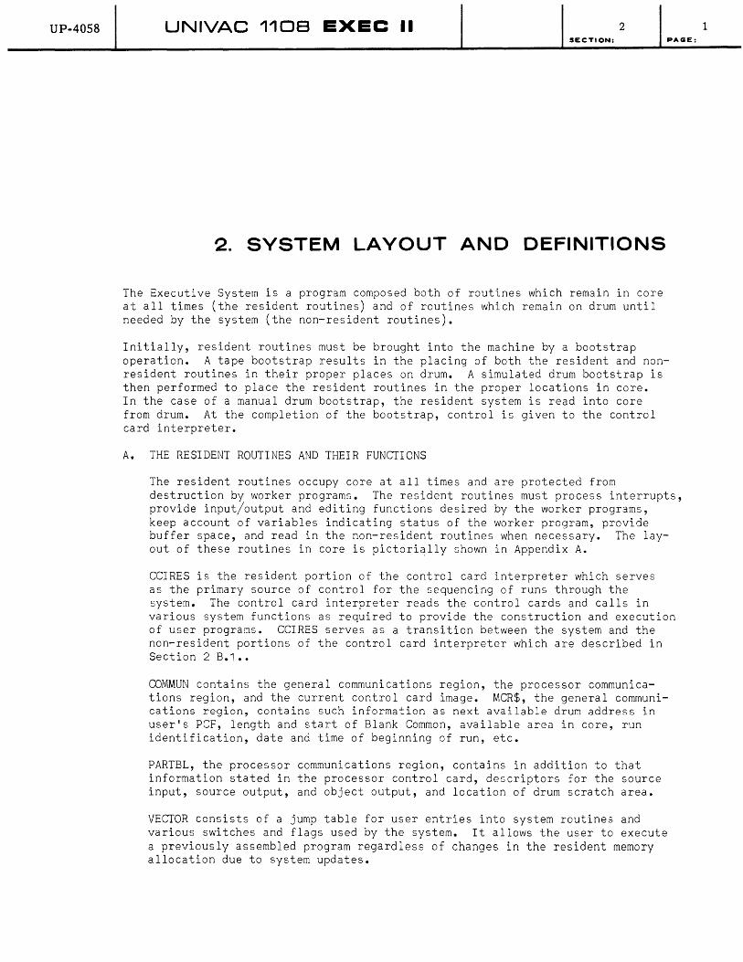
The Executive System is a program composed both of routines which remain in core at all times (the resident routines) and of routines which remain on drum until needed by the system (the non-resident routines).
Initially, resident routines must be brought into the machine by a bootstrap operation. A tape bootstrap results in the placing of both the resident and nonresident routines in their proper places on drum. A simulated drum bootstrap is then performed to place the resident routines in the proper locations in core. In the case of a manual drum bootstrap, the resident system is read into core from drum. At the completion of the bootstrap, control is given to the control card interpreter.
A. THE RESIDENT ROUTINES AND THEIR FUNCTIONS
The resident routines occupy core at all times and are protected from destruction by worker programs. The resident routines must process interrupts, provide input/output and editing functions desired by the worker programs, keep account of variables indicating status of the worker program, provide buffer space, and read in the non-resident routines when necessary. The layout of these routines in core is pictorially shown in Appendix A.
CCIRES is the resident portion of the control card interpreter which serves as the primary source of control for the sequencing of runs through the system. The control card interpreter reads the control cards and calls in various system functions as required to provide the construction and execution of user programs. CCIRES serves as a transition between the system and the non-resident portions of the control card interpreter which are described in Section 2 B.1 ••
COMMUN contains the general communications region, the processor communications region, and the current control card image. MCR$, the general communications region, contains such information as next available drum address in user's PCF, length and start of Blank Common, available area in core, run identification, date and time of beginning of run, etc.
PARTBL, the processor communications region, contains in addition to that information stated in the processor control card, descriptors for the source input, source output, and object output, and location of drum scratch area.
VECTOR consists of a jump table for user entries into system routines and various switches and flags used by the system. It allows the user to execute a previously assembled program regardless of changes in the resident memory allocation due to system updates.
1
UP-4058 UNIVAC 1108 EXEC II 2 SECTION:
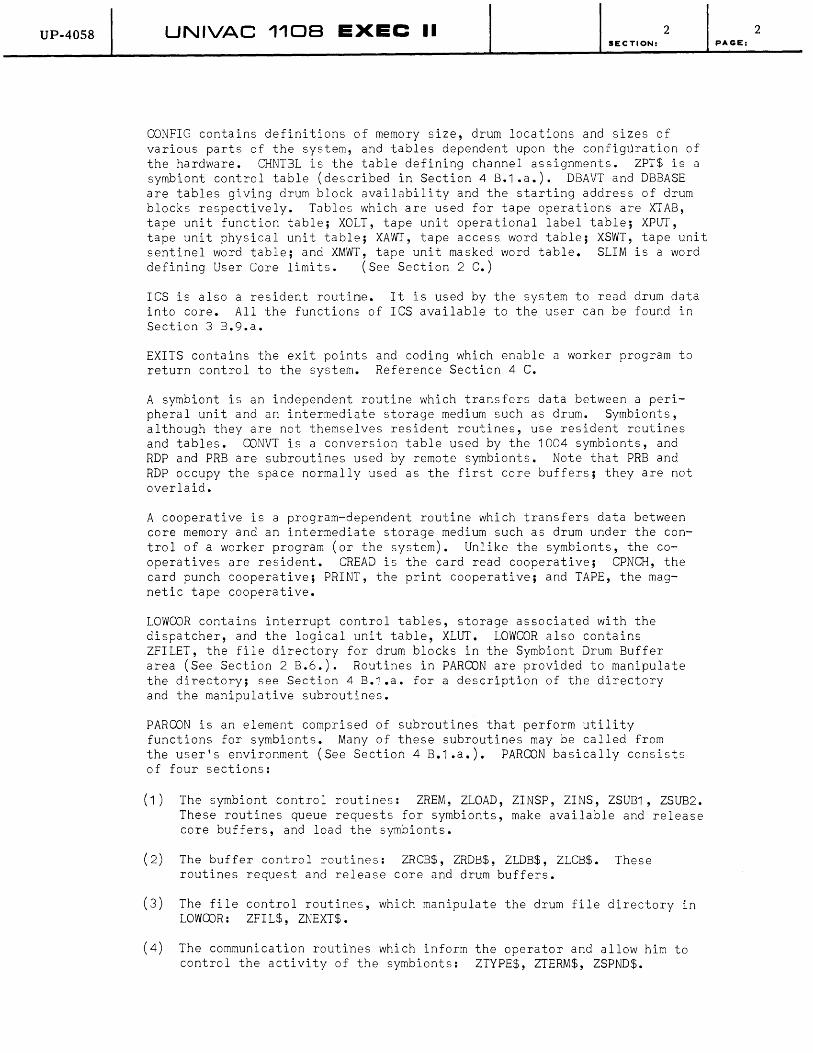
CONFIG contains definitions of memory size, drum locations and sizes of various parts of the system, and tables dependent upon the configuration of the hardware. CHNTBL is the table defining channel assignments. ZPT$ is a symbiont control table (described in Section 4 B.1 .a.). DBAVT and DBBASE are tables giving drum block availability and the starting address of drum blocks respectively. Tables which are used for tape operations are XTAB, tape unit function table; XOLT, tape unit operational label table; XPVI, tape unit physical unit table; XAWT, tape access word table; XSWT, tape unit sentinel word table; and XMWT, tape unit masked word table. SLIM is a word defining User Core limits. (See Section 2 C.)
ICS is also a resident routine. It is used by the system to read drum data into core. All the functions of ICS available to the user can be found in Section 3 B.9.a.
EXITS contains the exit points and coding which enable a worker program to return control to the system. Reference Section 4 C.
A symbiont is an independent routine which transfers data between a peripheral unit and an intermediate storage medium such as drum. Symbionts, although they are not themselves resident routines, use resident routines and tables. CONVT is a conversion table used by the 1004 symbionts, and RDP and PRB are subroutines used by remote symbionts. Note that PRB and RDP occupy the space normally used as the first core buffers; they are not overlaid.
A cooperative is a program-dependent routine which transfers data between core memory and an intermediate storage medium such as drum under the control of a worker program (or the system). Unlike the symbionts, the cooperatives are resident. CREAD is the card read cooperative; CPNCH, the card punch cooperative; PRINT, the print cooperative; and TAPE, the magnetic tape cooperative.
LOWCOR contains interrupt control tables, storage associated with the dispatcher, and the logical unit table, XLVI. LOWCOR also contains ZFILET, the file directory for drum blocks in the Symbiont Drum Buffer area (See Section 2 B.6.). Routines in PARCON are provided to manipulate the directory; see Section 4 B.1 .a. for a description of the directory and the manipulative subroutines.
PAR CON is an element comprised of subroutines that perform utility functions for symbionts. Many of these subroutines may be called from the user's environment (See Section 4 B.1.a.). PARCON basically consists of four sections:
(1) The symbiont control routines: ZREM, ZLOAD, ZINSP, ZINS, ZSUB1, ZSUB2. These routines queue requests for symbionts, make available and release core buffers, and load the symbionts.
(2) The buffer control routines: ZRCB$, ZRDB$, ZLDB$, ZLCB$. These routines request and release core and drum buffers.
(3) The file control routines, which manipulate the drum file directory in LOWCOR: ZFIL$, ZNEXT$.
(4) The communication routihes which inform the operator and allow him to control the activity of the symbionts: ZTYPE$, ZTERM$, ZSPND$.
2 PAGE:
UP-4058 UNIVAC 110B EXEC II 2 SECTION:
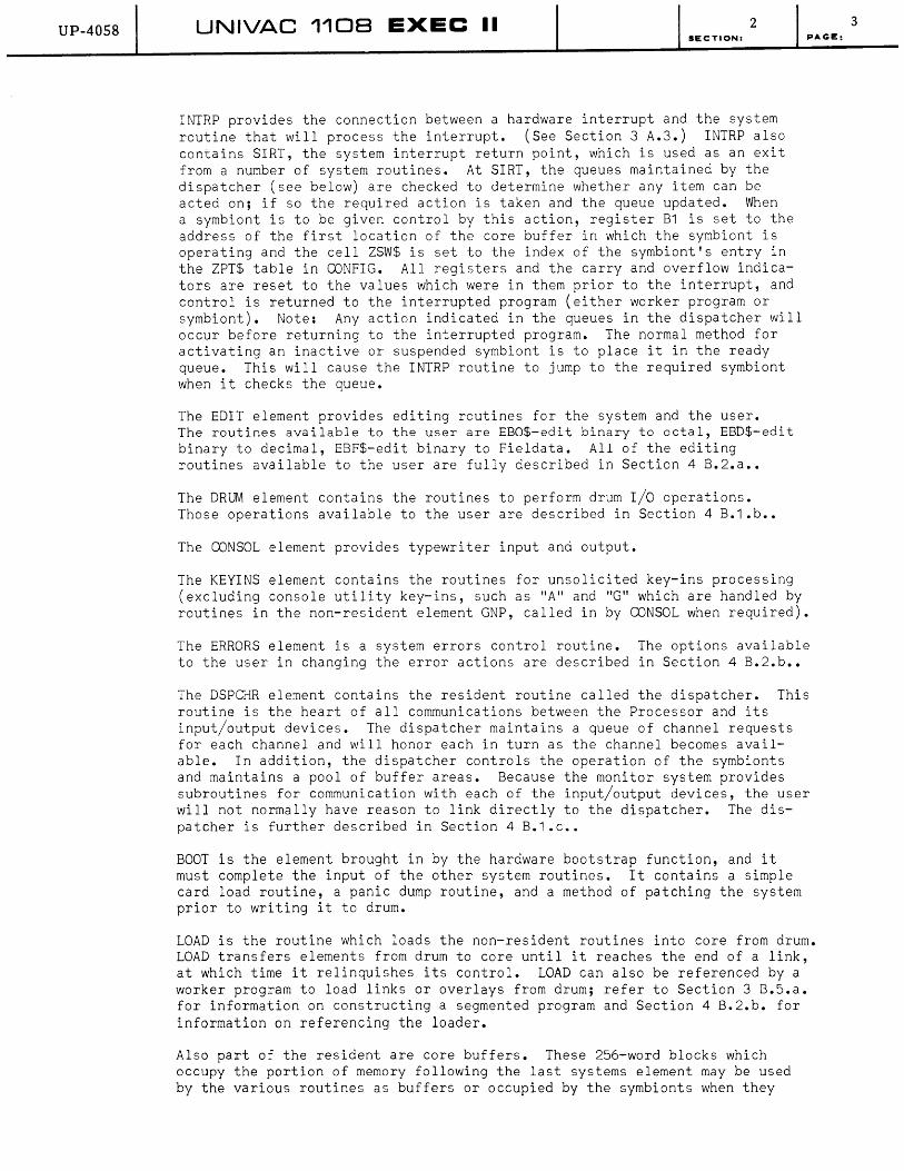
INTRP provides the connection between a hardware interrupt and the system routine that will process the interrupt. (See Section 3 A.3.) INTRP also contains SIRT, the system interrupt return point, which is used as an exit from a number of system routines. At SIRT, the queues maintained by the dispatcher (see below) are checked to determine whether any item can be acted on; if so the required action is taken and the queue updated. When a symbiont is to be given control by this action, register B1 is set to the address of the first location of the core buffer in which the symbiont is operating and the cell ZSW$ is set to the index of the symbiont's entry in the ZPT$ table in CONFIG. All registers and the carry and overflow indicators are reset to the values which were in them prior to the interrupt, and control is returned to the interrupted program (either worker program or symbiont). Note: Any action indicated in the queues in the dispatcher will occur before returning to the interrupted program. The normal method for activating an inactive or suspended symbiont is to place it in the ready queue. This will cause the INTRP routine to jump to the required symbiont when it checks the queue.
The EDIT element provides editing routines for the system and the user. The routines available to the user are EBO$-edit binary to octal, EBD$-edit binary to decimal, EBF$-edit binary to Fieldata. All of the editing routines available to the user are fully described in Section 4 B.2.a ••
The DRUM element contains the routines to perform drum I/O operations. Those operations available to the user are described in Section 4 B.1.b ••
The CONSOL element provides typewriter input and output.
PAGE:
The KEYINS element contains the routines for unsolicited key-ins processing (excluding console utility key-ins, such as "A" and "G" which are handled by routines in the non-resident element GNP, called in by CONSOL when required).
The ERRORS element is a system errors control routine. The options available to the user in changing the error actions are described in Section 4 B.2.b ••
The DSPCHR element contains the resident routine called the dispatcher. This routine is the heart of all communications between the Processor and its input/output devices. The dispatcher maintains a queue of channel requests for each channel and will honor each in turn as the channel becomes available. In addition, the dispatcher controls the operation of the symbionts and maintains a pool of buffer areas. Because the monitor system provides subroutines for communication with each of the input/output devices, the user will not normally have reason to link directly to the dispatcher. The dispatcher is further described in Section 4 B.1 .c ••
BOOT is the element brought in by the hardware bootstrap function, and it must complete the input of the other system routines. It contains a simple card load routine, a panic dump routine, and a method of patching the system prior to writing it to drum.
LOAD is the routine which loads the non-resident routines into core from drum. LOAD transfers elements from drum to core until it reaches the end of a link, at which time it relinquishes its control. LOAD can also be referenced by a worker program to load links or overlays from drum; refer to Section 3 B.5.a. for information on constructing a segmented program and Section 4 B.2.b. for information on referencing the loader.
Also part of the resident are core buffers. These 256-word blocks which occupy the portion of memory following the last systems element may be used by the various routines as buffers or occupied by the symbionts when they
3
UP-4058 UNIVAC 1108 EXEC II 2 SECTION:
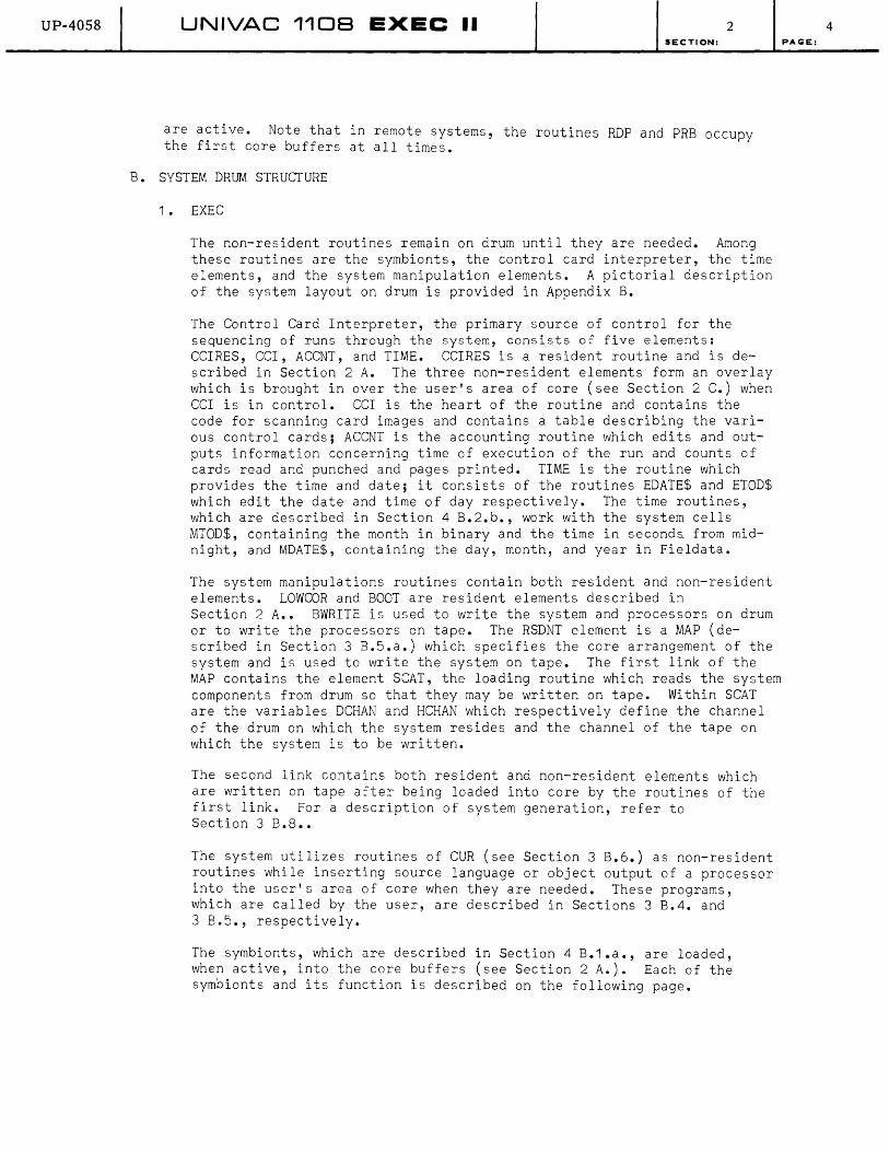
are active. Note that in remote systems, the routines RDP and PRB occupy the first core buffers at all times.
B. SYSTEM DRUM STRUCTURE
1. EXEC
The non-resident routines remain on drum until they are needed. Among these routines are the symbionts, the control card interpreter, the time elements, and the system manipulation elements. A pictorial description of the system layout on drum is provided in Appendix B.
The Control Card Interpreter, the primary source of control for the sequencing of runs through the system, consists of five elements: CCIRES, CCI, ACCNT, and TIME. CCIRES is a resident routine and is described in Section 2 A. The three non-resident elements form an overlay which is brought in over the user's area of core (see Section 2 C.) when CCl is in control. CCl is the heart of the routine and contains the code for scanning card images and contains a table describing the various control cards; ACCNT is the accounting routine which edits and outputs information concerning time of execution of the run and counts of cards read and punched and pages printed. TIME is the routine which provides the time and date; it consists of the routines EDATE$ and ETOD$ which edit the date and time of day respectively. The time routines, which are described in Section 4 B.2.b., work with the system cells MTOD$, containing the month in binary and the time in seconda from midnight, and MDATE$, containing the day, month, and year in Fieldata.
The system manipulations routines contain both resident and non-resident elements. LOWCOR and BOOT are resident elements described in Section 2 A.. BWRlTE is used to write the system and processors on drum or to write the processors on tape. The RSDNT element is a MAP (described in Section 3 B.5.a.) which specifies the core arrangement of the system and is used to write the system on tape. The first link of the MAP contains the element SCAT, the loading routine which reads the system components from drum so that they may be written on tape. Within SCAT are the variables DCHAN and HCHAN which respectively define the channel of the drum on which the system resides and the channel of the tape on which the system is to be written.
The second link contains both resident and non-resident elements which are written on tape after being loaded into core by the routines of the first link. For a description of system generation, refer to Section 3 B.8 ••
The system utilizes routines of CUR (see Section 3 B.6.) as non-resident routines while inserting source language or object output of a processor into the user's area of core when they are needed. These programs, which are called by the user, are described in Sections 3 B.4. and 3 B.5., respectively.
The symbionts, which are described in Section 4 B.1.a., are loaded, when active, into the core buffers (see Section 2 A.). Each of the symbionts and its function is described on the following page.
4 PAGE:

UP-4058 UNIVAC 1108 EXEC II I SECTION. 2 I PAGE, 5
PR1 Printer symbiont-transfers print files from drum to printer.
CR1 Card Read symbiont-transfers card read files from reader to drum.
CP1 Card Punch symbiont-transfers card punch files from drum to card punch.
DMP Dump symbiont-transfers print, punch, or read files from drum to tape.
LOD Load symbiont-transfers print, punch, or read files from tape to drum.
PR7 Remote print symbiont-transfers print files from drum to remote printer.
CR7 Remote read symbiont-transfers card read files from remote reader to drum.
CP7 Remote punch symbiont-transfers card punch files from drum to remote card punch.
CR4 1004 Card Read symbiont-transfers card read files from on site 1004 reader to drum.
PR4 1004 Print symbiont-transfers print files from drum to on site 1004 printer.
DLT Data Line Tape symbiont-transfers print files from drum to tape in DLT-5 format. See Appendix D 1.c •.
QR1 Paper tape read symbiont-transfers data from paper tape to magnetic tape.
Operating similar to the symbionts in that they are loaded into core buffers when needed, are the following routines.
TAP Handles tape assignments from the console (also called TASGN).
GNP Handles 'G' and 'A' Keyins (also called GPSW23).
THP Console operator's tape handler - See Section 4 B.1 .a ..
2. Processors and the Processor Scratch Area
A processor (not to be confused with the hardware term "central processor") is a special system program provided by UNIVAC for the 1108, which performs one of several functions relative to the construction of an object program. Three types of processors exist in the EXEC II system:
1. Language Processors (See Section 3 B.4.) 2. Element Manipulative Processors (See Section 3 B.5. and
3 B.6.) 3. Diagnostic Processors (PMD; See Section 3 B.9.)
In normal operation, the processors reside on drum until such time as one is called to perform its function. A processor is loaded and

UP-4058 UNIVAC 1108 EXEC •• - 2 SECTION:
executed as a worker program, much the same as a user's program (see Section 4 A.).
Two drum areas are used by the system for processors. The first is the area in which the processors reside, drum addresses 0035000 to 0420000 (octal notation). In this area, the processors are currently ordered as follows:
PMD (see Section 3 B.9.b.)
Allocator (see Section 3 B.5.c.)
CUR (see Section 3 B.6.c.)
MAP (see Section 3 B.5.a.)
1108 Assembler ( see Section 3 B.4.a.)
Procedure Definition Processor (see Section 3 B.4.a.)
COBOL Library Processor ( see Section 3 B.4.b.)
FORTRAN compiler ( see Section 3 B.4.c.)
LIBRY (see Section 3 B.7. )
COBOL compiler ( see Section 3 B.4.b.)
*LIFT or ALGOL (see below)
For those systems which contain LIFT as a processor (see Section 3 B.4.c.), it is at the end of the processor area; other systems contain an ALGOL compiler or a program which responds to an ALG control card and produces a message indicating that ALGOL is not available.
An area of drum is also reserved for the processors to use as working storage; this area is called "Processor Scratch Area" and its location is variable depending on the type of system provided. The starting address of this area is contained in CONFIG (see Section 2 A.) as the symbol ASCRH$. The area is currently defined as follows (see also Appendix B):
1 Drum System -02000000 to 02377777 * 1 Drum Extended System -02000000 to 05377777 * 2 Drum System -03000000 to 04777777 *
* (octal notation)
NOTE: The last location in the processor scratch area is defined by the system as the maximum legal drum address for worker programs; i.e., any attempt to write into a higher drum address by a worker program will be considered an error.
3. Library PCF
PAGE:
The Library PCF is a program complex file stored on drum for use by all worker programs. (A Program Complex File is a random-access file of program components.) It contains elements (see Section 3 B.7.), which may be called by user programs but no element may be added, deleted or modified. To make changes to the Library, it is necessary to rebuild it in
6
UP-4058 UNIVAC 1108 EXEC II 2 SECTION:
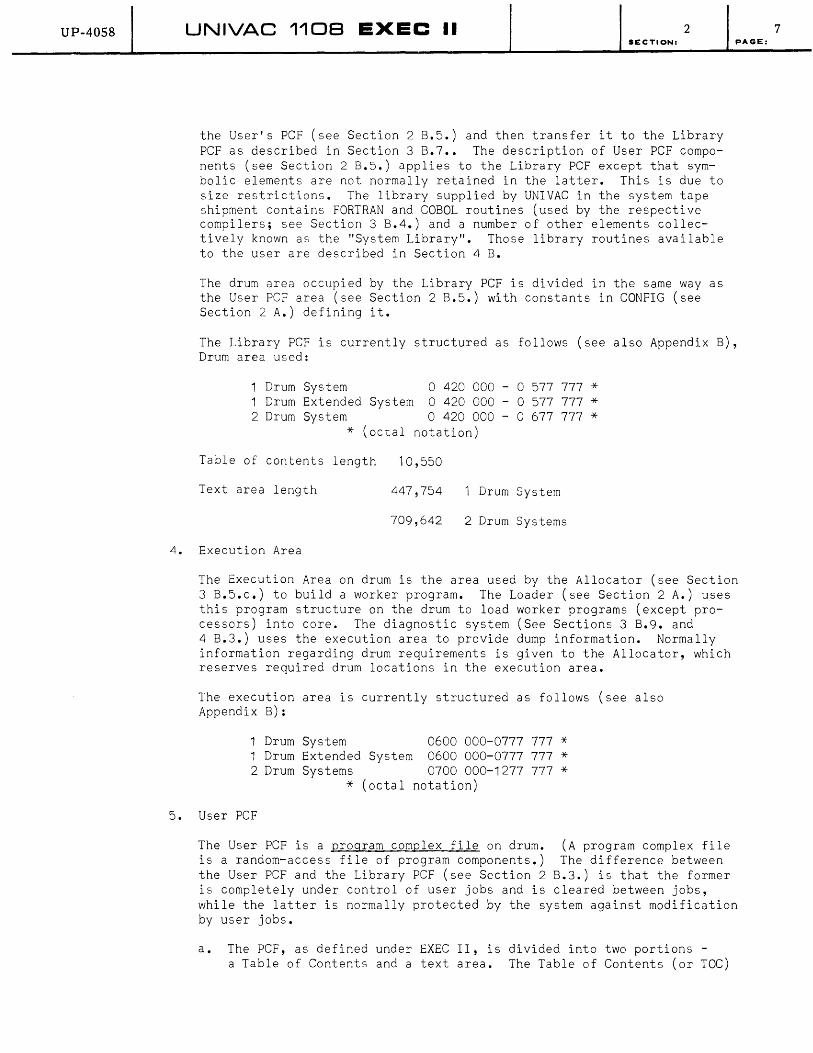
the User's PCF (see Section 2 B.5.) and then transfer it to the Library PCF as described in Section 3 B.7 •• The description of User PCF components (see Section 2 B.5.) applies to the Library peF except that symbolic elements are not normally retained in the latter. This is due to size restrictions. The library supplied by UNIVAC in the system tape shipment contains FORTRAN and COBOL routines (used by the respective compilers; see Section 3 B.4.) and a number of other elements collectively known as the "System Library". Those library routines available to the user are described in Section 4 B.
The drum area occupied by the Library PCF is divided in the same way as the User PCF area (see Section 2 B.5.) with constants in CONFIG (see Section 2 A.) defining it.
PAGE:
The Library PCF is currently structured as follows (see also Appendix B), Drum area used:
1 Drum System 0 420 000 - 0 577 777 * 1 Drum Extended System 0 420 000 - 0 577 777 * 2 Drum System 0 420 000 - 0 677 777 *
* (octal notation)
Table of contents length 10,550
Text area length 447,754 Drum System
709,642 2 Drum Systems
4. Execution Area
5.
The Execution Area on drum is the area used by the Allocator (see Section 3 B.S.c.) to build a worker program. The Loader (see Section 2 A.) uses this program structure on the drum to load worker programs (except processors) into core. The diagnostic system (See Sections 3 B.9. and 4 B.3.) uses the execution area to provide dump information. Normally information regarding drum requirements is given to the Allocator, which reserves required drum locations in the execution area.
The execution area is currently structured as follows (see also Appendix B):
1 Drum System 0600 000-0777 777 * 1 Drum Extended System 0600 000-0777 777 * 2 Drum Systems 0700 000-1277 777 *
* (octal notation)
User PCF
The User PCF is a program complex file on drum. (A program complex file is a random-access file of program components.) The difference between the User PCF and the Library PCF (see Section 2 B.3.) is that the former is completely under control of user jobs and is cleared between jobs, while the latter is normally protected by the system against modification by user jobs.
a. The PCF, as defined under EXEC II, is divided into two portions -a Table of Contents and a text area. The Table of Contents (or TOC)
7
UP-4058 UNIVAC 1108 EXEC II 2 SECTION: PAGE:
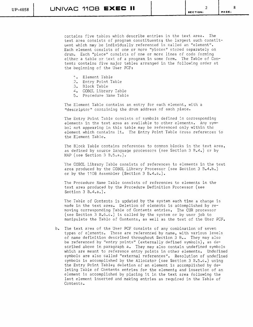
contains five tables which describe entries in the text area. The text area consists of program constituents; the largest such constituent which may be individually referenced is called an "element". Each element consists of one or more "pieces" stored separately on drum. Each "piece" consists of one or more lines of code forming either a table or text of a program in some form. The Table of Contents contains five major tables arranged in the following order at the beginning of the User PCF:
1. Element Table 2. Entry Point Table 3. Block Table 4. COBOL Library Table 5. Procedure Name Table
The Element Table contains an entry for each element, with a "descriptor" containing the drum address of each piece.
The Entry Point Table consists of symbols defined in corresponding elements in the text area as available to other elements. Any symbol not appearing in this table may be referenced only within the element which contains it. The Entry Point Table cross references to the Element Table.
The Block Table contains references to common blocks in the text area, as defined by source language processors (see Section 3 B.4.) or by MAP (see Section 3 B.5.a.).
The COBOL Library Table consists of references to elements in the text area produced by the COBOL Library Processor (see Section 3 B.4.b.) or by the 1108 Assembler (Section 3 B.4.a.).
The Procedure Name Table consists of references to elements in the text area produced by the Procedure Definition Processor (see Section 3 B.4.a.).
The Table of Contents is updated by the system each time a change is made in the text area. Deletion of elements is accomplished by removing corresponding Table of Contents entries. The CUR processor (see Section 3 B.6.c.) is called by the system or by user job to manipulate the Table of Contents, as well as the text of the User PCF.
b. The text area of the User PCF consists of any combination of seven types of elements. These are referenced by name, with various levels of name definition described throughout Section 3 B •• They may also be referenced by "entry points" (externally defined symbols), as described above in paragraph a. They may also contain undefined symbols which are meant to reference entry points in other elements. Undefined symbols are also called "external references". Resolution of undefined symbols is accomplished by the Allocator (see Section 3 B.5.c.) using the Entry Point Table; deletion of an element is accomplished by deleting Table of Contents entries for the element; and insertion of an element is accomplished by placing it in the text area following the last element inserted and making entries as required in the Table of Contents.
8
UP-40S8 UNIVAC 1108 EXEC II 2 SECTION:
The seven types of elements which may be in the User PCF in any order are:
1. Symbo lic 2. Absolute (see Section 3 B.5.c.) 3. Relocatable (see Section 3 B.4.) 4. Processed MAP (see Section 3 B.5.a.) 5. Compressed Symbolic 6. COBOL Library (see Section 3 B.4.b.) 7. PROC (or procedure) (see Section 3 B.4.a.)
PAGE:
A symbolic element (types 1 or 5) consists of a single "piece", which is the symbolic coding to be input to a processor (see Sections 3 B.4. - 3 B.6.). The piece consists of images of the cards input by the programmer.
An absolute element (type 2) consists of a single piece divided into logical groupings for each program link and preceded by two tables. The first is a header table which defines the size of the element, sizes of storage blocks required, and references to the link table. The link table follows the header table and contains references to the links which follow, with space for the loader to mark "active" the parts of the link which are in core. Each link consists of a block of absolute code with beginning and ending points marked and a set of Diagnostic Tables which are used by the diagnostic routines (see Sections 3 B.9., and 4 C.).
A relocatable element (type 3) consists of two pieces called the "preamble" and the text. The preamble contains entries for each location counter up to the highest number counter used, entries for each undefined symbol, and entries for each externally-defined symbol listed in the Entry Point Table of the TOC. The text is a block of relocatable binary card images, each of which contains the relocatable code words of the program and corresponding relocation information.
A processed MAP element (type 4) consists of a number of tables corresponding to the MAP directives described in Section 3 B.5.a •• These tables are arranged into a "piece" for each link, plus a "piece" consisting of the DEF table, which contains entries originating in DEF directives (described in Section 3 B.5.a.).
A COBOL Library element (type 6) consists of two pieces. The first piece consists of COBOL card images as input to the COBOL Library Processor; the second is a preamble containing the labels (up to 30 COBOL characters) of the COBOL paragraph entries in the first piece.
A PROC element (type 7) consists of two pieces. The first piece consists of assembler procedures in card images; the second is a preamble containing the labels of the PROC and NAME lines in the first piece.
c. The User PCF occupies a predetermined portion of drum in every EXEC II system (see also Appendix B.).
1 Drum System 1 Drum Extended System 2 Drum Systems
* (octal notation)
01000000-02000000 * 01000000-02000000 * 01300000-03000000 *
9

UP-4058 UNIVAC 1108 EXEC II 2 SECTION: PAGE:
Note that the first location in the User PCF is defined by the system as the minimum legal drum address for worker programs, and worker programs may not write below this address. The size of the User PCF and its components is defined by constants in CONFIG (see Section 2 A.).
6. Symbiont Drum Buffers
A symbiont (see Section 2 B.1.) is an independent routine which transfers data between a peripheral device and an intermediate storage medium. Most symbionts use the drum as the intermediate storage medium; for this reason buffers are provided on the drum for files handled by symbionts.
Each buffer, or drum block, is a 256 word area on drum. The resident system (see Section 2 A.) contains routines which control the use of these buffers. Utilization of symbiont buffers by worker programs is also provided for by means of system subroutines with worker program entries (see Section 4 B.1 .b.).
Access is also provided to the symbiont buffers for co-operative routines, which are program-dependent resident routines which transfer data between the drum and the worker program (see Section 2 A.).
The drum area established for symbiont buffers is currently defined as follows (see also Appendix B):
1 Drum System 1 Drum Extended System 2 Drum System
* (octal notation)
C. WORKER PROGRAM AREAS IN CORE AND DRUM
02 400 000-02 777 777 * 05 400 000-05 777 777 * 05 000 000-05 777 777 *
Worker programs are restricted to specified areas in core and drum. Generally, these areas are the portions of storage not reserved by the system. The exceptions to this rule are the areas reserved for symbiont, drum, and core buffers; these may be used by a worker program which properly requests them (see Section 4 B.1 .b.).
The main areas available to the worker program are defined in Appendixes A and B. All core between the upper limit of COMMUN (the last resident routine in lower core) and the lower limit of ICS (the first resident routine in upper core) is available to the worker program. On the drum, the worker program may use the entire area encompassed by the User PCF and the Processor Scratch area. Caution is advised in utilizing drum areas, since these areas serve other functions.
The last three words of PARTBL (in COMMUM; see Section 2 A.) and the first word of MCR$ (in COMMUN) contain information useful in determining worker program areas as follows:
PARTBL+16 07750* Core size (65) +17 07751* Address of start of User PCF (minimum legal drum address) +18 07752* Address of end of Processor Scratch area
(maximum legal drum address) +19 07753* Address of start of Processor Scratch area
MCR$ +0 00754* Address of next available location in User PCF
*Core addresses in octal notation.
10

UP-4058 UNIVAC 1108 EXEC II 3 SECTION: PAGE:
3. SYSTEM CONTROLS
A. EXECUTIVE CONTROL FUNCTIONS
This section outlines EXEC controls over the operating environment of the machine. The basic structure of this environment (covered in detail in other sections) is as follows:
System Control
Worker Programs
EXEC Operator
Symbionts
Programmer jobs are defined by the programmer's "RUN DECK" and usually include one or more worker programs which require the major part of the computing capability of the machine; these are run serially.
Symbionts are I/O limited programs which perform most of the hardware functions of the machine. These operate concurrent with and essentially independent of the programmer's job and each other.
Control over machine operations is shared between the operator and the EXEC. Decisions regarding the use of symbionts and error recovery procedures are the domain of the operator while the EXEC insures that the programmer's requirements and operating requirements are efficiently fulfilled.
To do its supervisory job, EXEC controls the multiprogram environment by keeping check on all running programs, facilitating the sharing of hardware, and reserving interrupt control to itself. These functions are outlined in succeeding paragraphs.
1. Multiprogram Control
At any given time several programs may be in operation. These include:
a. An EXEC control routine, such as CCI (see Section 2 B.1 .), or at most one worker program (see Section 2.).
1

UP-4058 UNIVAC 1108 EXEC II 3 SECTION:
1. Multiprogram Control
At any given time several programs may be in operation. These include:
a. An EXEC control routine, such as CCI (see Section 2 B.1 .), or at most one worker program (see Section 2.).
b. One or more symbionts (see Section 2 B.1., 4 B.1 .a.).
To insure that these programs do not interfere with one another, EXEC is entered each time control is to be transferred from one program to another. At this time EXEC stores all information pertinent to the program releasing control, restores the pertinent information for the program demanding control, and releases control to the latter.
Worker programs release control only when interrupted (see Sections
PAGE:
3 A.2. and 3 A.3.) or when complete. Symbionts take control only through interrupts after they are initialized and release control while waiting for an interrupt or when interrupted or complete. EXEC control routines such as CCI gain control when the system is initially loaded or when the worker program is completed and release control when interrupted or when a worker program is turned on.
EXEC also maintains control of the hardware environment by keeping track of assigned areas in core and drum and all peripheral devices.> Any attempt by a worker program to utilize areas restricted to system routines causes an interrupt to occur, and EXEC terminates the worker program. EXEC also thwarts efforts by a worker program to utilize peripheral devices incorrectly, such as attempting to use a device already in use or calling for a channel which does not contain the proper equipment or does not exist. Hardware controls are detailed in Section 3 A.2. and interrupt controls in Section 3 A.3 ••
To properly fulfill its supervisory function certain instructions as well as the portions of core used by the resident (see Section 2 A.) and registers 0, 32-64, and 80-87 are reserved exclusively for EXEC use. The console, one card channel, and one printer channel must also be reserved. To protect the user from ambiguous definitions, all symbols used by EXEC for cross-communication (or for entry points from worker programs) contain the symbol "$". While this symbol is not reserved, it is strongly recommended that users avoid it so as not to chance duplication between their own symbols and those of EXEC.
All function codes which are legal on the 1108 and do not appear in the list below may be used by worker programs operating under EXEC lIon the 1108. No attempt is made by EXEC II to flag the use of instructions in the 1108 repertoire which are illegal on the 1107.
2

UP-4058
2.
UNIVAC 1108 EXEC II 3 SECTION: PAGE:
The following list of reserved instructions must not be used by worker programs, since proper operation of EXEC II depends on its exclusive use of these instructions. 1108 Assembler mnemonics and octal function codes are shown, with a note, "(1108)" or "(1107)" for functions which exist in only one of the two machines. Functions which are not otherwise noted are in the repertoire of both the 1107 and 110B. For further information refer to the 110B Processor and Storage Manual (UP 4053).
W 7200 (1107 ) HKJ 7405 DOC 7510 LL 7211 (1107 ) HJ 7405 LFCM 7511 ER 7211 (11 OB) AAIJ 7407 JFC 7512 PAIJ 7213 LIC 7500 AFC 7513 SCN 7214 (11 OB) LICM 7501 AACI 7514 LIF 7215 ( 11 OB) JIC 7502 PACI 7515 LSL 7216 (11 OB) DIC 7503 ACI 7516 (1107 ) lSI 7314 (1108) LOC 7504 PCI 7517 (1107) SIL 7315 (1108 ) LOCM 7506 LCR 7316 (11 OB) TOC 7507
Hardware Control
The Executive, in its function as a supervisory program, maintains control of certain portions of the hardware. This consists of controlling input/output, responding to hardware interrupts, reserving portion of core and drum, and maintaining queues of buffer and I/O requests.
To aid in control, the Executive maintains tables for interrupt control, (see Section 3 A.3.) magnetic tape assignment, channel requests and channel status, symbiont activity, and core and drum availability. Although the worker program need not reference these tables directly, the user should be aware of the fact that the Executive must keep the tables up to date.
Through its co-operatives and symbionts (described in Section 4 B.1 .a.), the system acts as an interface between a worker program and the peripheral devices. The roles of the worker program, the symbionts, the cooperatives, and the Executive itself are shown pictorially in diagram A (see Section 3-5). Notice that many of the symbionts and co-operatives utilize the drum for buffering purposes. The use of this fast-access I/O device allows the system to return control without having to wait for the availability of the slower I/O device requested. If no buffers are available for symbiont or co-operative, however, the system will not return control until it has obtained a buffer by the action of a symbiont or co-operative releasing one.
The co-operatives are resident routines (refer to Section 2 A.) and are directly available to the worker program. Symbionts, however, are nonresident and can be controlled only by the system or by manual intervention in the form of a command to the system. Symbionts, if not already active, are loaded into core and activated in the following instances:
a. a full block of line images is to be transferred to the printer or card punch,
3
UP-40S8 UNIVAC 110B EXEC II 3 SECTION:
b. the operator enters a key-in via the console informing the system that he wishes to activate a symbiont,
c. The operator at a remote 1004 depresses the proper alteration switches to indicate that he wishes to begin transmission. (Refer to Section 5 C.)
A worker program can theoretically perform r/o operations without interfacing with the Executive. However, since the system keeps account of the status of the various r/o devices, to prevent system destruction the worker program should request channels through the dispatcher when using direct r/o (Refer to Section 4 B.1 .c.).
Magnetic tape, drum, paper tape, and console r/o operations are not handled through cooperatives, but library routines are available to the worker program for performing these operations. The use of library routines for magnetic tape and drum operations is described in Section 4 B.1.b., console r/o in Section 4 B.1 .b., and paper tape r/o in Section 4 B.1 .e ••
The Executive reserves for its own use certain portions of core and drum (refer to Sections 2 A., 2 B., and 2 C., and Appendixes A and B). Attempts by a worker program to write into these reserved areas will result in an error termination. However, the worker program may request core and drum buffers for its own use (refer to Section 4 B.1 .a.). The user should exercise caution in requesting buffers, for if a worker program has buffers assigned to its control it is denying the Executive the use of these buffers. When the system has less buffers available, it may have to wait longer to answer the request for a buffer by a symbiont or a co-operative, thereby wasting valuable central processor time or even causing the system to "hang" if no buffers can be made available.
4 PAGE:

UP-4058 UNIVAC 1108 EXEC II
I WORKER PROGRAM I EXEC II (1108 CORE)
INPUT OUTPUT
Co-operative Co-operative (uses core (uses core buffer for buffer for
data) data)
INTERMEDIATE STORAGE (NORMA LL Y DRUM)
t CORE BUFFERS (1108 CORE)
INPUT OUTPUT Symbiont Symbiont
+ + Data Buffer Data Buffer
INPUT OUTPUT Device Devi ce
(E. G. CARD (E. G. PRINTER) READER)
Diagram A, Representation of the Relationships of Worker Program, Symbiont, and Co-operatives (Console Operator Controls not shown). Also see Table of Symbionts (Section 4 B.1.a.)
3 5 SECTION: PAGE:

UP-4058 UNIVAC 110B EXEC II 3 SECTION:
3. Interrupt Contro I
Much of the activity occurring at any time in the operation of the 1108 involves some kind of interrupt. An interrupt is a notification to the system that some special condition has occurred; these are described below. To facilitate this notification certain memory locations are reserved (refer to 1108 Processor and Storage Manual UP 4053) to which an unconditional jump is made when an interrupt occurs; the P-register, which contains the location of the next instruction to be executed, is not affected by this jump. Under EXEC II, the interrupt locations are reserved to the system, and are loaded with entrances to system routines such as INTRP (see Section 2 A.). This routine handles the condition which caused the I/O interrupt and returns control to the routine which was interrupted, at the location which was in the P-register when the interrupt occurred. Certain interrupts may be modified by the user, through corresponding system routines (see Section 4 B.2.b.). The following interrupts are handled by EXEC II:
a. External Request interrupts for each channel. These occur when the peripheral device on the channel demands the attention of the computer.
b. Input Data Termination interrupts for each channel. These occur when the transfer of a data block from a peripheral device to core terminates. This interrupt is internally controlled, since the size of the block to be transferred is internally specified.
c. Output Data Termination interrupts for each channel. These are the output equivalent of the input interrupt described in paragraph b.
d. Function Termination interrupts for each channel. These occur when a peripheral device attached to the channel acknowledges the function, or command, transferred to it from core. This is obviously also an internal interrupt.
e. Error Interrupts (as indicated in the 1108 Processor and Storage Manual, UP 4053). These occur when specified errors (such as divide overflow, illegal instruction, or attempt to write into protected areas of core) are made by the operating program. EXEC II provides for user modification of the error interrupt entry points (see Section 4 B.2.b.).
f. Real-Time Clock interrupt. This occurs when a specified amount of time has elapsed (as indicated by the decrementation of Register R ~, the real-time clock, through zero). EXEC II provides routines for usage of the real-time clock (see Section 4 B.2.a.).
g. External Synchronization interrupt. This occurs when a real-time device demands access to the 1108, so as to provide the capability of synchronizing the device with the 1108.
6 PAGE:

UP-4058 UNIVAC 1108 EXEC II 3 SECTION:
B. USER CONTROL OF SYSTEM
The primary control over the system available to the user is the control card. This is, by definition, any card image with a "masterspace" (octal 00 punched as "7-8" on the card) in column 1, and is usually "free-form" which means fields are not limited by the card columns in which they are placed. Computer runs are organized into jobs within which may be any number of programs. Between jobs, the system clears worker-program areas in core and drum (see Section 2 C.), all indicators applying to worker programs, and frees tape drives assigned previously to worker programs. The usage of control cards and other similar controls over system operation is described in this section.
1. Job EXEC Communication
a. RUN Control Card
Definition: The RUN card is a control card which marks the beginning of a job. It is identified by the word "RUN" in the card name field and contains a job priority code, an identification name, an account name, an estimate of running time and print output, and a print channel designation and a punch channel designation (see Appendix C 3. for format). All fields except the card name field, the identification name and the account name are optional and may be omitted. The RUN card fields are described below.
(1) Job Priority
This is a single alphabetic character (A-Z) in the "option" field of the card which specifies the order in which jobs are executed by the system. Jobs with priority toward the beginning of the alphabet are taken before those with priority toward the end of the alphabet. If the field is omitted, "D" is supplied by the system.
(2) Identification Name
This is a field of from one to six characters from the set A - Z , y)-9, +, =, ., $ • B 1 an k s are i 11 ega 1. I tis a conventional identification which is normally supplied by the programmer.
(3) Account Name
This is a field similar to the identification name field; however, it is normally used by the computer center for job accounting, and specifications for this field are normally supplied by the center.
7 PAGE:
UP-4058 UNIVAC 1108 EXEC II 3 SECTION:
(4) Run Time Estimate
This is a decimal integer (0-1440) interpreted by the system as the number of whole minutes estimated for the job. A console typeout, "MAX TIME", informs the operator as soon as this estimate has been exceeded. If the field is omitted, "5" is supplied by the system.
(5) Print Output Estimate
This is a decimal integer (0-999999) interpreted by the system as the number of pages of print output estimated for the job. A console typeout, "MAX PAGES", informs the operator as soon as this estimate has been exceeded. If the field is omitted, "50" is supplied by the system.
(6)* Print Channel Designation
This is a decimal integer interpreted by the system as the channel on which print files are to be output. It is used to override the system's selection of the output channel, e.g., when running remotely via a 1004 (see Section 5 C.) in order to print at the 1108 site, or to a remote site when the run deck was input at the 1108 site. It should also be specified if special forms are to be mounted on the printer. If the field is omitted, the system supplies the number of the standard on-line printer.
(7)* Punch Channel Designation
This field is similar to the print channel designation field; it is interpreted by the system as the channel on which punch files are to be output. If the field is omitted, the system supplies the number of the standard on-line punch.
System Response:
When the RUN card is encountered by CCI (see Section 2 B.1 .), the EXEC ascertains that the previous run has been finalized; this will have been done if a FIN card (see Section 3 B.3.a.) had previously been encountered. If not~ the end-action normally performed by the FIN card is done, and the new job announced by typing the RUN card at the console.
*NOTE: Any printer or punch available to a system may be designated as "special". This prevents the unit from being referenced unless it is explicitly specified on a RUN card. Card readers may also be designated as "special"; any job input via a "special" reader channel will have its output directed to the same channel in the absence of explicit channel designations on the RUN card. Only 1004 Card Processors (on site or remote) may be designated as "special" readers. Such "special" designations will be supplied by UNIVAC Systems Programming on request.
8 PAGE:
UP-4058 UNIVAC 1108 EXEC II 3 SECTION:
The RUN card is then checked to ascertain that it contains valid identification name and account name fields, which are stored along with the estimates for run time and print output in the MCR$ table
PAGE:
in COMMUN (see Section 2 A.). If print and punch channels are designated, these are checked to determine that they specify valid channels with the proper equipment, according to CONFIG (see Section 2 A.); if so, the channel number is stored (in CONFIG) for use in setting up the file directory entry in PARCON (see Section 2 A.) for this file.
Current time of day is stored in the MCR$ table (starting time), the TOC (user's PCF) is initialized, the starting address of processor scratch area is stored in the MCR$ table, HDG option is turned off (see Section 3 B.3.), and if no error was detected on the card, the RUN card is placed in the print output file, after which CCl is then re-entered to read another control card. If an error was found on the card, it is handled as an invalid control card (see Section 3 B.10.).
b. ASG Control Card
Definition: The ASG card is a control card which calls for the assignment of a magnetic tape unit for the current job. It is identified by the word "ASG" in the card name field and contains an options code and an assignment equation in which a "logical" label (the program unit assignment) is equated to an "operational" label (normally the title or identification of the tape file). The absolute hardware designation for a tape unit may also appear on the card under certain conditions. The ASG card fields are described below (see Appendix C 3. for format).
(1) Options Codes
This is a single alphabetic character (C, E, F, H, K, L, 0, R, X) which specifies tape density, parity, rewind, and certain conversion options available (see Appendix C 2. for options) for all assignments on the card. Up to four options codes may be used; the system supplying codes for high density, odd parity, no rewind, and no conversion for omitted codes. The field may not be used if the "assignment equation" field is omitted.
(2) Absolute Hardware Designation
This is a pair of decimal integers separated by a slash (/), specifying the absolute channel and the absolute unit assignments respectively. If this field is used, a maximum of a single assignment equation may be associated with it. A maximum of ten hardware equations (with associated assignment equations) separated by commas, may be specified. If no assignment equation appears on the card, the hardware channel is reserved, and EXEC will expect the next card to be an ASG card with the assignment equation for the specified unit or another hardware designation; up to ten such cards, with no assignment equations and collectively specifying up to ten hardware units, may be used. Since an assignment card is anticipated, its omission creates an error (see Section 3 B.10.). If the field is omitted, the operator will be notified by a typeout, "MOUNT (operational label)", and must then provide the absolute assignment.
9
UP-4058 UNIVAC 1108 EXEC II 3 SECTION:
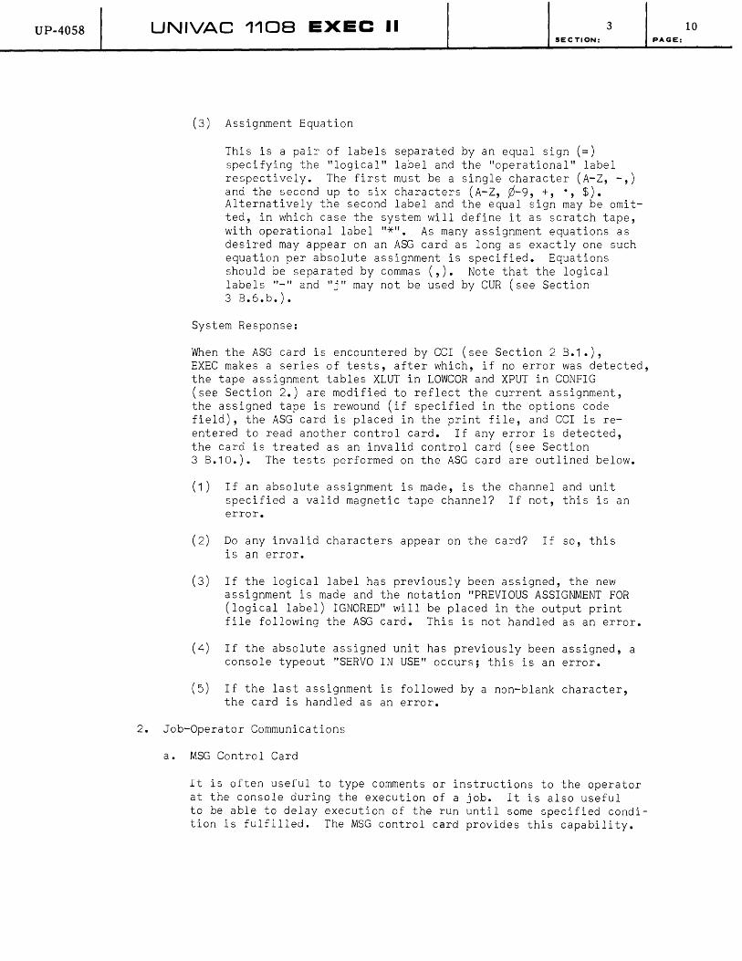
(3) Assignment Equation
This is a pair of labels separated by an equal sign (=) specifying the "logical" label and the "operational" label respectively. The first must be a single character (A-Z, -,) and the second up to six characters (A-Z, ¢-9, +, ., $). Alternatively the second label and the equal sign may be omitted, in which case the system will define it as scratch tape, with operational label "*". As many assignment equations as desired may appear on an ASG card as long as exactly one such equation per absolute assignment is specified. Equations should be separated by commas (,). Note that the logical labels "_" and "j" may not be used by CUR (see Section 3 B.6.b.).
System Response:
When the ASG card is encountered by CCI (see Section 2 B.1.), EXEC makes a series of tests, after which, if no error was detected, the tape assignment tables XLUT in LOWCOR and XPUT in CONFIG (see Section 2.) are modified to reflect the current assignment, the assigned tape is rewound (if specified in the options code field), the ASG card is placed in the print file, and CCI is reentered to read another control card. If any error is detected, the card is treated as an invalid control card (see Section 3 B.10.). The tests performed on the ASG card are outlined below.
(1) If an absolute assignment is made, is the channel and unit specified a valid magnetic tape channel? If not, this is an error.
(2) Do any invalid characters appear on the card? If so, this is an error.
(3) If the logical label has previously been assigned, the new assignment is made and the notation "PREVIOUS ASSIGNMENT FOR (logical label) IGNORED" will be placed in the output print file following the ASG card. This is not handled as an error.
(4) If the absolute assigned unit has previously been assigned, a console typeout "SERVO IN USE" occurs; this is an error.
(5) If the last assignment is followed by a non-blank character, the card is handled as an error.
2. Job-Operator Communications
a. MSG Control Card
It is often useful to type comments or instructions to the operator at the console during the execution of a job. It is also useful to be able to delay execution of the run until some specified condition is fulfilled. The MSG control card provides this capability.
10 PAGE:

UP-40S8 UNIVAC 1108 EXEC II 3 SECTION:
The MSG card is a control card which causes a message to be typed at the console and included in the print file output. It is identified by the word "MSG" in the card name field and contains an options code field and a message. The options code field may contain either the letter "N", which suppresses typing of the card at the console, or the letter "H", which causes a delay to be initiated, or both. In the absence of these options, the system simply types the card out at the console, places it in the output print file and re-enters CCI (see Section 2 B.1.) to read another control card. The operator is notified of the delay, if called for, by additional typeout, "WAIT" following the message. To proceed, the operator must then type in "S", which removes the delay condition. (See Appendix C 3. for format.)
3. System I/O Definition
In normal system operation, jobs are selected from the drum, where they are placed by the operator, using symbionts (see Sections 2 B.1., 2 B.6., and 4 B.1 .a.). A print file is placed on the drum for each job to be printed via a symbiont. If required by the job, a punch file may also be placed on the drum for symbiont action. Several control cards are used to modify these input/output files, or to assist the system in defining them. This section will describe these control cards.
a. EOF, FIN, and COL Control Cards
These control cards are used in defining card files; the EOF card is used to punctuate input or output data files, the FIN card is used to punctuate input job files and the COL card is used to change between 80-column mode, and 90-column mode when the input source is an on-site 1004. These cards differ from other control cards in that they are not "free-form"; the card name field must be in columns 3-5 of the card, with blanks in columns 2 and 6. If the card is not specifically this form, it will be considered an invalid control card (see Section 3 B.10.). The remainder of the FIN or COL card is ignored by the system; the EOF card may contain identification information pertinent to the data file, as in the case when relocatable files are punched out
PAGE:
of the user PCF, for example (see Section 2 B.5.). See Appendix C 3. for formats.
(1) System Response to FIN Card
When a FIN card is encountered by CCI (see Section 2 B.1 .), the current job is terminated. This involves clearing worker program areas (see Section 2 C.), freeing all tape units not in use by the system, closin~ print and punch files, clearing all indicators referring to the job being terminated, bypassing redundant FIN cards, and setting a systems mode switch so the system will expect a RUN card next. While bypassing extraneous FIN cards, the system is idling, and the operator will be so notified by the typeout "IDLE". If the next card (other than FIN card) is not a RUN card, an error exists (see Section 3 B.10.).
11

UP-40S8 UNIVAC 1108 EXEC II SECTION:
(2) System Response to EOF card
When an EOF card is encountered by eel, it is simply placed in the output print file and bypassed. However, if the card-read co-operative (see Section 48.1.a.) encounters an EOF card in response to a read request by a worker program, the character in column 7 of the EOF card is stored in register A¢, and an abnormal return to the user's program is made. This permits the worker program to delimit input data files. (Any other control card encountered in this circumstance will cause A¢ to be set negative and the abnormal return taken; under no circumstances will the control card image be available to the worker program.)
(3) System Response to COL card
3
When a eOL card is encountered by CR4, the 1004 card-read symbiont (see Section 4 8.1.a.), switches are set to change the mode of reading from 80 to 90 or 90 to 80. Since the system provides translation for input/output files referencing 1004, the image received by the worker program will be the same whether the 1004 is an SO-column, SO/9C-column, or 90-column device; the normal mode will be 90 for the latter and SO for the two former*. Thus, to read SO-column cards on a 90 device, or to read 90-column cards on an SO device, or to mix SO-column and 90-column on either an 80 or 90 device, the COL card is required to notify CR4 that a mode change is needed. The COL card is discarded after the mode change, and is not given to either the system or worker program. The system, other than CR4, will consider the eOL card an error (see Section 3 B.10.).
b. TPR and DPR Control Cards
The TPR and DPR cards are control cards which define the printfile storage medium. The DPR card, identified by the word DPR in the card name field contains no other information, and signals the system that print-files are to be stored on drum. The TPR card, identified by the word TPR in the card name field, contains an options codes field and a label field, and signals the system that print files are to be stored on magnetic tape. The DPR card should be used to reset after a TPR card has been used. (See Appendix C 3. for formats.) Note that print-files which are stored on drum will be printed as soon as possible, the system activating the print
*NOTE: SO-column images are 14 computer words in length; 90-column images are 15 computer words in length. System routines will ignore the last word of a 90-column image; however, worker programs will receive the entire 15 words. Normal mode may be changed by operator selection as well as by the COL card.
12 PAGE:
UP-40S8 UNIVAC 1108 EXEC II 3 SECTION:
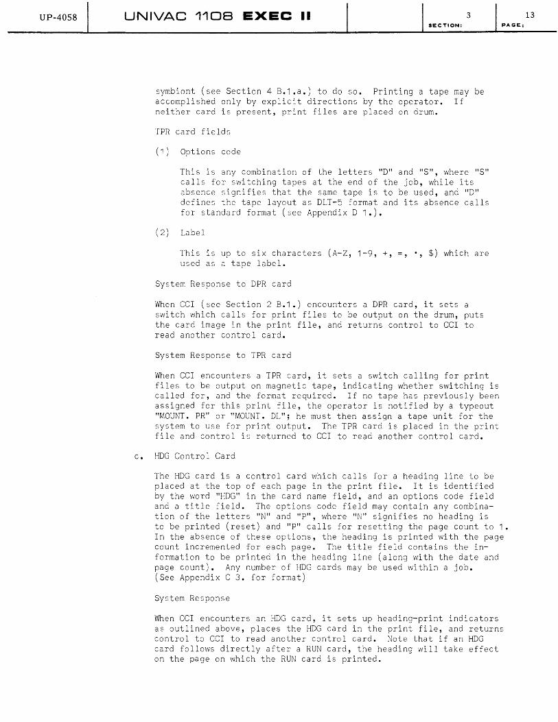
symbiont (see Section 4 B.1 .a.) to do so. Printing a tape may be accomplished only by explicit directions by the operator. If neither card is present, print files are placed on drum.
TPR card fields
(1) Options code
This is any combination of the letters "D" and "S", where "s" calls for switching tapes at the end of the job, while its absence signifies that the same tape is to be used, and "D" defines the tape layout as DLT-5 format and its absence calls for standard format (see Appendix D 1.).
(2) Labe 1
This is up to six characters (A-Z, 1-9, +, =, used as a tape label.
System Response to DPR card
$) which are
When eel (see Section 2 B.1.) encounters a DPR card, it sets a switch which calls for print files to be output on the drum, puts the card image in the print file, and returns control to eel to read another control card.
System Response to TPR card
When eel encounters a TPR card, it sets a switch calling for print files to be output on magnetic tape, indicating whether switching is called for, and the format required. If no tape has previously been assigned for this print file, the operator is notified by a typeout "MOUNT. PR" or "MOUNT. DL"; he must then assign a tape unit for the system to use for print output. The TPR card is placed in the print file and control is returned to eel to read another control card.
c. HDG Control Card
The HDG card is a control card which calls for a heading line to be placed at the top of each page in the print file. It is identified by the word "HDG" in the card name field, and an options code field and a title field. The options code field may contain any combination of the letters "N" and "P", where "N" signifies no heading is
PAGE:
to be printed (reset) and "P" calls for resetting the page count to 1. In the absence of these options, the heading is printed with the page count incremented for each page. The title field contains the information to be printed in the heading line (along with the date and page count). Any number of HDG cards may be used within a job. (See Appendix C 3. for format)
System Response
When CCI encounters an HDG card, it sets up heading-print indicators as outlined above, places the HDG card in the print file, and returns control to CCI to read another control card. Note that if an HDG card follows directly after a RUN card, the heading will take effect on the page on which the RUN card is printed.
13
UP-40S8 UNIVAC 1108 EXEC II 3 SECTION: PAGE:
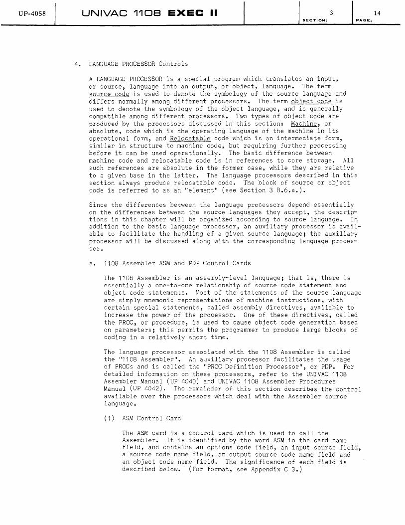
4. LANGUAGE PROCESSOR Controls
A LANGUAGE PROCESSOR is a special program which translates an input, or source, language into an output, or object, language. The term source code is used to denote the symbology of the source language and differs normally among different processors. The term object code is used to denote the symbology of the object language, and is generally compatible among different processors. Two types of object code are produced by the processors discussed in this section: Machine, or absolute, code which is the operating language of the machine in its operational form, and Relocatable code which is an intermediate form, similar in structure to machine code, but requiring further processing before it can be used operationally. The basic difference between machine code and relocatable code is in references to core storage. All such references are absolute in the former case, while they are relative to a given base in the latter. The language processors described in this section always produce relocatable code. The block of source or object code is referred to as an "element" (see Section 3 B.6.a.).
Since the differences between the language processors depend essentially on the differences between the source languages they accept, the descriptions in this chapter will be organized according to source language. In addition to the basic language processor, an auxiliary processor is available to facilitate the handling of a given source language; the auxiliary processor will be discussed along with the corresponding language processor.
a. 1108 Assembler ASM and PDP Control Cards
The 1108 Assembler is an assembly-level language; that is, there is essentially a one-to-one relationship of source code statement and object code statements. Most of the statements of the source language are simply mnemonic representations of machine instructions, with certain special statements, called assembly directives, available to increase the power of the processor. One of these directives, called the PROC, or procedure, is used to cause object code generation based on parameters; this permits the programmer to produce large blocks of coding in a relatively short time.
The language processor associated with the 1108 Assembler is called the "1108 Assembler". An auxiliary processor facilitates the usage of PROCs and is called the "PROC Definition Processor", or PDP. For detailed information on these processors, refer to the UNIVAC 1108 Assembler Manual (UP 4040) and UNIVAC 1108 Assembler Procedures Manual (UP 4042). The remainder of this section describes the control available over the processors which deal with the Assembler source language.
(1) ASM Control Card
The ASM card is a control card which is used to call the Assembler. It is identified by the word ASM in the card name field, and contains an options code field, an input source field, a source code name field, an output source code name field and an object code name field. The significance of each field is described below. (For format, see Appendix C 3.)
14

UP-4058 UNIVAC 1108 EXEC II 3 SECTION: PAGE:
(a) Options Code Field
This is one or more letters (A,C,I,J,L,M,N,P,Q,S,W,X,Z) which modify assembly. (For details regarding options, see Appendix C 2 •• )
(b) Input Source Field
This is a single character (A-Z*) specifying where the source code is situated when the assembler is called. "A"-"Z" specify a logical tape unit, properly positioned to the source language element; "*" specifies the User PCF on the drum (see Sections 2 B.S. and 3 B.6.) as the location of the source element, while the absence of a character calls for card input. The source language is on punched cards directly behind the control card in the input file.
(c) Source Code Name Field
This is a pair of labels separated by a slash (/). Each label consists of up to six characters (A-Z, ¢-9, +, ., $) and represents the name and version of the source element, respectively. If the version is omitted, the slash should be omitted, and the processor uses spaces for the version field.
(d) Output Source Code Name Field
This field is identical in form to the source code name field except that the first character of the name and the version must be alphabetic (A-Z). It is used to specify that an updated source language element (which may be identical to the original source element) is to be stored in the User PCF. In the absence of this field, the processor discards the output source element. Note, however, that the original source element remains in the User PCF if it was input from there.
(e) Object Code Name Field
This field contains a name and version similar to the output source name field; if the version is omitted, the processor uses the output source code name, and if this is missing, the processor uses the original source code name. In addition, this field may contain a "flag", which consists of a string of alphabetic characters enclosed in parentheses. If the flag is omitted, the processor supplies zero as a flag. The flag is used as an additional identifier in conjunction with the XQT, ABS, and seD control cards (see Section 3 B.5.b.). Object code elements are always output to the User PCF (see Section 2 B.5.).
15

UP-4058 UNIVAC 1108 EXEC II 3 SECTION: PAGE:
System Response to ASM card
When CCI (see Section 2 B.1.) encounters an ASM card, it places it in the print file and stores parameters from the card and from CONFIG in PARTBL, a parameter table in COMMUN (see Section 2 A.). If tape or card input is specified, the system assumes the next item in the specified input device to be the input element. If drum input is specified, the user PCF (see Section 2 B.5.) is searched for the source element; if not found there, the library PCF is similarly searched. If still not found, or if it is not uniquely defined, or if its drum location cannot be properly determined from the Table of Contents entry (see Section 2 B.5.), an error message is added to the print file (see Section 3 B.1.) and the card is bypassed, CCl being re-entered to read another control card. If punch options have been specified, ELT cards (see Section 3 B.6.a.) are punched for the required elements. The assembler is then loaded by CCIRES (see Section 2 A.) as a worker program (see Section 4 A.2.) and produces the required object element and print or punch output according to the options codes field. After completion CClRES is re-entered, where a check is made for error options; if errors occurred, the message
"ERRS IN ELEMENT PRODUCED"
is placed in the print file. CCl is then reloaded to insert the relocatable element in the User PCF if the output element is error-free, or if option to ignore errors has been used, and to continue by reading another control card.
(2) PDP Control Card
The PDP card is a control card which is used to call the PROC Definition Processor. This processor makes entries in the Table of Contents of the user PCF while loading the procedure into the user PCF. These entries permit other elements to call procedures thus processed (see Section 2 B.5.). There is no difference between the source language, 1108 Assembler procedures, and the object language for this processor. The card contains the same fields as the ASM card, except for the output source name field, for the reason just stated. (For format, see Appendix C 3.). The options code field must be selected from the set (A,C,l,J,L,P,W,X).
System Response to PDP Card
The PDP card is handled similarly to the ASM card, with the following exceptions:
(a) The input element may be either source code or the output of the PROC Definition Processor.
(b) If no list option is used, no list is produced (see Appendix C 2.).
(c) No relocatable element is produced.
16

UP-4058 UNIVAC 1108 EXEC II 3 SECTION: PAGE:
b. COBOL: COB and CLP Control Cards
COBOL (acronym for Common Business Oriented Language) is a problemoriented, or machine-independent language; this implies that the relationship between the source code and the object code is normally one-to-many, since a single step in the solution of a problem may involve many machine operations. The translation of COBOL statements to object code is performed by a compiler, which in the 1107 and 1108, does not involve the production of assembly-level code. COBOL statements are directly translated to relocatable code by the COBOL compiler. This processor is controlled by the COB card.
To simplify even further the building of COBOL programs, a COBOL Library Processor is provided in the EXEC II System. This places COBOL source elements into a COBOL library in the User PCF (see Section 2 B.S. and 3 B.6.) so that they may be incorporated into COBOL programs. COBOL library elements are called into COBOL programs by the "COPY" and "INCLUDE" verbs. The COBOL Library Processor is controlled by the CLP card. (For details of COBOL language and the associated processors, refer to UNIVAC 1108 COBOL Manual UP 4048.)
(1) COB Control Card
The COB card is a control card which calls the COBOL compiler. Its form is similar to that of the ASM card (see Section 3 B.4.a.). The options code field must be selected from the set (A,B,D,E,I,J,L,M,N,O,P,R,S,U,V,W,X,Z). Refer to Appendix C for format and options.
System Response to COB card
The COB card is handled similarly to the ASM card, with the following exceptions:
(a) A special option letter, "K", is required to make COBOL Library elements available through the "COPY" verb.
(b) More than one relocatable element may be produced; these will be integrated into a single program when allocated (see Section 3 B.5.c.) or executed.
(c) The COBOL compiler, instead of the assembler, is called.
(2) The CLP Control Card
The CLP card is a control card used to call the COBOL Library Processor. It is similar in form to the PDP card (see Section 3 B.4.a.). Options codes for the CLP card must be selected from the set (A,I,J,L,S,X). Refer to Appendix C for format and options.
System Response to the CLP card
The CLP card is handled similarly to the PDP card (see Section 3 B.4.a.) with the exception that the input element may be either a source element or COBOL library element, and the COBOL Library Processor instead of the PROC Definition Processor, is called.
17
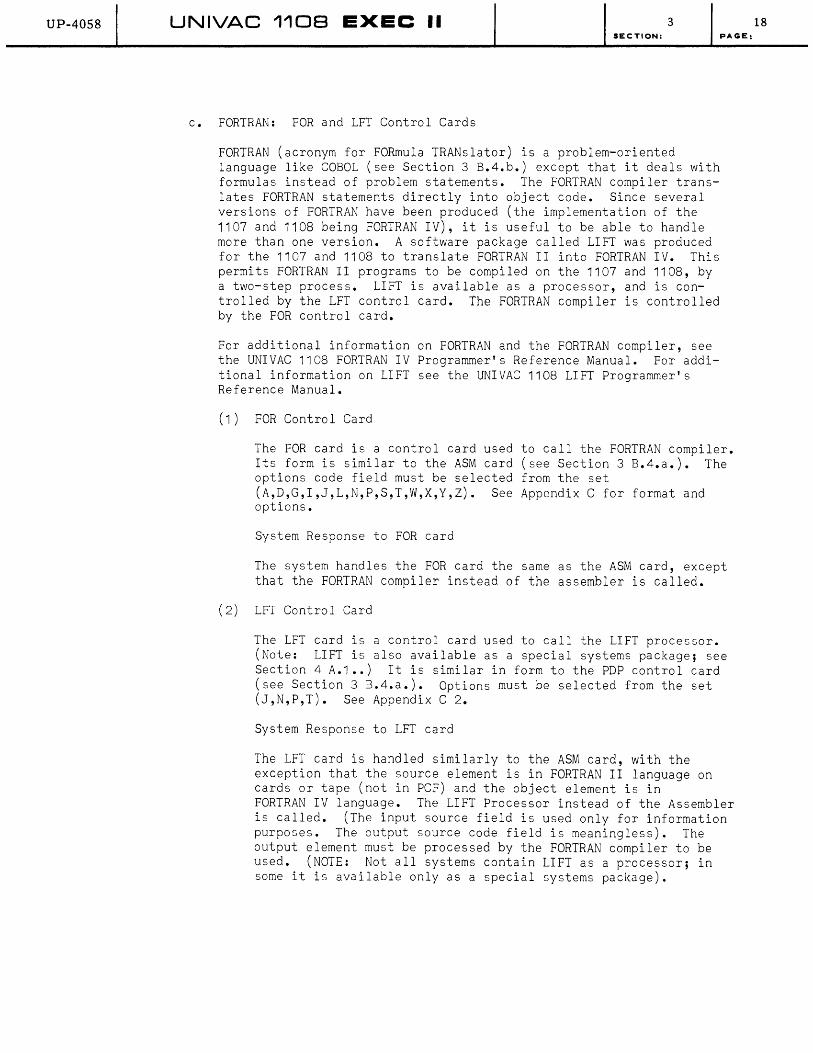
UP-40S8 UNIVAC 1108 EXEC II 3 SECTION:
c. FORTRAN: FOR and LFT Control Cards
FORTRAN (acronym for FORmula TRANslator) is a problem-oriented language like COBOL (see Section 3 B.4.b.) except that it deals with formulas instead of problem statements. The FORTRAN compiler translates FORTRAN statements directly into object code. Since several versions of FORTRAN have been produced (the implementation of the 1107 and 1108 being FORTRAN IV), it is useful to be able to handle more than one version. A software package called LIFT was produced for the 1107 and 1108 to translate FORTRAN II into FORTRAN IV. This permits FORTRAN II programs to be compiled on the 1107 and 1108, by a two-step process. LIFT is available as a processor, and is controlled by the LFT control card. The FORTRAN compiler is controlled by the FOR control card.
For additional information on FORTRAN and the FORTRAN compiler, see the UNIVAC 1108 FORTRAN IV Programmer's Reference Manual. For additional information on LIFT see the UNIVAC 1108 LIFT Programmer's Reference Manual.
(1) FOR Control Card
PAGE:
The FOR card is a control card used to call the FORTRAN compiler. Its form is similar to the ASM card (see Section 3 B.4.a.). The options code field must be selected from the set (A,D,G,I,J,L,N,P,S,T,W,X,Y,Z). See Appendix C for format and options.
System Response to FOR card
The system handles the FOR card the same as the ASM card, except that the FORTRAN compiler instead of the assembler is called.
(2) LFT Control Card
The LFT card is a control card used to call the LIFT processor. (Note: LIFT is also available as a special systems package; see Section 4 A.1 •• ) It is similar in form to the PDP control card (see Section 3 B.4.a.). Options must be selected from the set (J,N,P,T). See Appendix C 2.
System Response to LFT card
The LFT card is handled similarly to the ASM card, with the exception that the source element is in FORTRAN II language on cards or tape (not in PCF) and the object element is in FORTRAN IV language. The LIFT Processor instead of the Assembler is called. (The input source field is used only for information purposes. The output source code field is meaningless). The output element must be processed by the FORTRAN compiler to be used. (NOTE: Not all systems contain LIFT as a processor; in some it is available only as a special systems package).
18

UP-40S8 UNIVAC 1108 EXEC II 3 SECTION:
d. Source Language Correction
Each language processor produces, if called for, an output source language element. The listing produced by the processor matches
PAGE:
that element, and sequence numbers are assigned to each line of source code in it. This permits the programmer to make corrections to source elements without resubmitting the original card deck. A source language element on the drum or on magnetic tape may be merged with corrections on cards. Source code lines to be inserted or overlaid should appear the same on the correction card as they would in an original input deck. These cards, along with correction location directive cards tell the processor where and how to make corrections. The form of the correction location directive card is:
-line 1, line 2
where the "_" in column 1 identifies the card as a correction location directive and the two line number fields correspond to line numbers in the source element to be updated. Three types of corrections may thus be entered:
(1) Deletions:
"Line 1" specifies the line number of the first line to be deleted, "Line 2" specifies the line number of the last line to be deleted. All lines in the source element from "Line 1" to "Line 2" inclusive are deleted.
(2) Overlays:
The form of this card is similar to that of the deletion card; source code lines to replace the deleted lines are on cards which follow the correction location directive. One or more lines are thus deleted and replaced with one or more lines; the number of replacement lines may be greater than, less than, or equal to the number of deleted lines.
(3) Insertions:
"Line 1" specifies the number of the line preceding the insert. The comma and "Line 2" are omitted. Source code lines to be inserted directly after the line specified as "Line 1".
It should be noted that little error checking is done on correction decks. The programmer should use care to ascertain that "Line 1" is smaller than "Line 2" on deletion and overlay cards, and that the correction deck is sequenced by ascending "Line 1" fields, in addition to checking that the directives specify corrections as he wishes them. If these precautions are not taken, the action of the processor is unspecified; an "infinite loop" is a possible result, the processor cycling without producing anything.
19

UP-4058 UNIVAC 1108 EXEC II 3 SECTION:
Corrections are merged into the output source language element. The programmer may store this as an updated source element or may ignore it, in which case, the correction deck will not be reflected in the source element in the User's PCF (see Sections 2 5. and 3 B.6.). Correction cards should follow the control card which calls the language processor; input source field on that card should specify the location of the original element.
5. ALLOCATOR Control
a. MAP Processor: MAP Control Card
The MAP (memory allocation processor) is a special program which produces a structural plan of a program for use by the Allocator
PAGE:
(see Section 3 B.5.c.). It requires a set of input directives which will be described in paragraph 2 of this section. The MAP card is a control card used to call the Memory Allocation Processor. The form of MAP card is similar to the ASM card (see Section 3 B.4.a.). The options field must be selected from the set (A,I,J,N,P,S,W,X). Refer to Appendix C for format and options. The output of the Memory Allocation Processor is called "MAP" and is stored in the User PCF (see Section 2 B.5.). The name given to the MAP is used as a program name by the allocator. MAP directives follow the MAP control card in the RUN deck.
(1) System Response to MAP Control Card
The system handles the MAP control card as it does the ASM control card except that the output element is a processed MAP, and the Memory Allocation Processor, instead of the assembler, is called. Errors encountered during processing are indicated in Section 6. Note that source language corrections may be made to MAP elements (see Section 3 B.4.d.).
(2) MAP directives
The following is a listing of directives acceptable to the MAP processor. These are explained in succeeding paragraphs, with special terminology defined as required. The format of every directive card is "free-form", i.e., fields are not limited to specific card columns. Three fields appear on the card; the first is a label associated with the directive, and begins with a non-blank character in column 1. The label is up to six characters long from the set (A-Z, 0-9, +, ., $), the first of which must be alphabetic (A-Z). It may be omitted if desired. The second field is the directive itself; this field starts with the first non-blank character following the first blank column of the card. Directives must be selected from the following set (this field may not be omitted).
SEG ENT BLK DEF CHN FIX USE SET
20

UP-4058 UNIVAC 1108 EXEC II 3 SECTION: PAGE:
The third field on the directive card is an information field; this may contain a number, a symbol, or a pseudo-algebraic formula representing a portion of a program, depending on the directive. It may not be omitted. The directive may be continued on a second card by use of a semicolon on the first card; the semicolon causes the remainder of the current card and all leading blanks on the next card to be ignored. The maximum number of directives which may be supplied is not specified; however, no more than 90 BLK directives and 29 CHN directives may be used, and not more than 50 USE directives may appear in any link. The description of the various directive cards follows.
(a) SEG
This card defines a program segment. A program segment is defined as that portion of memory which is committed by a single reference to the loader. Within a segment, subsegments may be defined as portions of the segment which overlay one another. Segments may be built up from relocatable elements, common blocks (see BLK directive explanation), or other segments, and similarly with sub?egments. The information field of the card contains the names of the portions of the segment interconnected by pseudo-algebraic symbols denoting their relationships; the following is a list of symbols which may be used:
"-"
" " ,
"*"
is a binary operation indicating that two constituents are to occupy memory simultaneously.
is a binary operation indicating that two constituents (subsegments) are to occupy the same part of memory, thus overlaying one another. (They will begin at the same memory address, though they may not end at the same address if they are of different sizes.)
is an unary operation signifying that the constituent which follows is to be automatically loaded. Automatic loading is specified when the c~nstituent is referenced by a jump to an entry point within it (see Section 2 B.5.). When.the program is executed, a jump will be made to the entry point specified, if the constituent is in core, or the loader will load it if it is not in core and then jump. As opposed to this, manual loading requires a call to EXEC to load the the constituent, whether or not it is currently in core, (see Section 4 B.2.b.), before jumping to a specified point.
"(),, are used to indicate grouping. Normally the "_" has greater precedence than ",". The parentheses may alter the order of their application or may be used to delimit a constituent, similar to algebraic notation.
21

UP-4058 UNIVAC 1108 EXEC II 3 SECTION:
For simplicity in setting up a segment, a diagramming technique is used. A vertical co-ordinate is employed to specify different points in time, not necessarily sequenced, while a horizontal co-ordinate specifies increasing memory addresses. In the following examples, "A", "B", and "c" are constituents of the segment as indicated in the preceding discussion. "NAME" is the label as previously described; if omitted, the name of the first constituent on the card will be used. The directive card format is indicated on the left and corresponding diagram on the right.
NAME SEG A-8
A 8
NAME SEG A, 8
A
8
NAME SEG A-(8, C)
8
A
C
NAME SEG A, (8-C)
A or
NAME SEG A, 8-C
B C I It should be noted that parentheses on the SEG card
PAGE:
define a separate calIon the loader and thus define each constituent within parentheses as a segment. Constituents not within parentheses must not be separately loaded. Thus in the third example above "A(B-C)" calls for "B" and "C" to be loaded separately, while "A,B-C" calls for "B" and "C" to be loaded simultaneously. By specifying a separate SEG card where the loading requirement desired cannot be specified on a single card, flexibility is achieved. For example:
NAME SEG A-(B-C,D) specifies separate loading of "B" and ItCH
E SEG B-C specifies simultaneous loading
NAME SEG A-(E,D) of "B" and "c"
22

UP-4058 UNIVAC 1108 EXEC II 3 SECTION:
Structurally, the two cases presented are otherwise identical. In specifying automatic loading, the "*" applies only to those subsegments in the parentheses level being introduced.
Every segment which is not made part of another segment
PAGE:
is called an "independent" segment. The fixed part of all independent segments will always be in memory as the program is being executed; no overlap is permitted in the memory allocated for independent segments. If the Allocator determines that an element which is not mentioned on a SEG card is to be included in the program, it will be an independent segment if more than one independent segment references it. It will become a dependent portion of the independent segment which contains the only reference to it. In the absence of a MAP, all elements are considered to be independent segments.
The Allocator assigns storage for core and drum. The same segment description serves for both, congruent areas being assigned in both, regardless of the particular amount of storage required of each medium.
(b) BLK
The BLK directive is used to identify a labeled common block to the Memory Allocation Processor. The label field is not meaningful, and the information field contains the names of one or more common blocks separated by commas. A common block is a communication area in core or drum; if it is used within a link (see paragraph on CHN directive), it may have a name and is then called "labeled common"; if it is used as a communication between links, it must not have a name and is called a "blank common". Common blocks are specified in COBOL or FORTRAN (see Section 3 B.4.) by means of a COMMON statement. In the 1108 Assembler, the INFO directive is the means for specifying storage requirements, including common blocks. The INFO directive takes the following form:
label INFO g c1, c2, •••
where "label" is the name of the group, "g" is the group number and "c1, c2, ••• " indicates a list of location counter numbers which are included in the group. Storage is assigned sequentially beginning with c1. The significance of the group number is as follows:
o Absolute; no storage required, no relocation
Assign bank storage
2 Assign bank 2 storage
3 Assign drum storage
4 Assign "blank common" (bank 2) storage
5 Assign bank 1 "labeled common" storage
23

UP-4058 UNIVAC 1108 EXEC II 3 SECTION: PAGE:
6 Assign bank 2 "labeled common" storage
7 Assign drum "labeled common" storage
33 Assign bank data
34 Assign bank 2 data
37 Assign bank 1 "labeled common" data (initial contents loaded)
38 Assign bank 2 "labeled common" data (initial contents loaded)
In the absence of an INFO directive, all even numbered location counters (including zero) are assigned to group 2, and all odd number location counters are assigned to group 1, in order of increasing location counter number.
The name of a common block may not duplicate the name of any element or any other common block in the program. Normally common blocks are referenced relative to their base instead of by externally-defined symbols (see Section 3 B.6.); external references may be used, however, if no ambiguity is introduced. The size of a common block will be determined by its maximum reference, thus assuring sufficient storage. Different block lengths may be specified by different elements.
Initial contents may be specified for a common block in any segment which references it. If more than one segment specifies initial contents, the last such segments loaded will supply the values used. If the segment which specifies initial contents for a common block is reloaded, the common block is re-initialized. Specification of initial contents in FORTRAN is accomplished by means of the BLOCK DATA feature. For COBOL, the initial contents are specified by means of VALUE statements. In 1108 Assembler programs, the special groups 33, 34, 37, 38 are used to designate data blocks with initial values; 33 and 34 may be used for noncommon areas, while 37 and 38 specify common areas. No location counter appearing in an INFO statement having one of these group numbers may appear in any other INFO statement. These groups must be assembled separately from groups 0-7, and all location counters used must be explicitly referenced in an INFO line. Data blocks (common or otherwise) may not contain external references (see Section 2 B.5.) and may not include information which requires relocation. A block may appear on both a BLK card and a SEG card in any order, in which case the Allocator handles it along with the segment specified on the SEG card.
Common blocks which do not appear on a SEG card will be allocated according to group number, or according to the Allocator's rules for handling segments which are not mentioned on SEG cards.
24
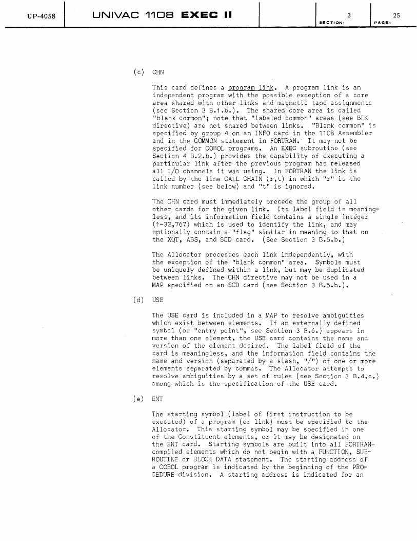
UP-4058 UNIVAC 1108 EXEC II 3 SECTION: pAGE:
(c) CHN
This card defines a program link. A program link is an independent program with the possible exception of a core area shared with other links and magnetic tape assignments (see Section 3 B.1.b.). The shared core area is called "blank common"; note that "labeled common" areas (see BLK directive) are not shared between links. "Blank common" is specified by group 4 on an INFO card in the 1108 Assembler and in the COMMON statement in FORTRAN.' It may not be specified for COBOL programs. An EXEC subroutine (see Section 4 B.2.b.) provides the capability of executing a particular link after the previous program has released all I/O channels it was using. In FORTRAN the link is called by the line CALL CHAIN (r,t) in which "r" is the link number (see below) and "t" is ignored.
The CHN card must immediately precede the group of all other cards for the given link. Its label field is meaningless, and its information field contains a single integer (1-32,767) which is used to identify the link, and may optionally contain a "flag" similar in meaning to that on the XQT, ABS, and SCD card. (See Section 3 B.5.b.)
The Allocator processes each link independently, with the exception of the "blank common" area. Symbols must be uniquely defined within a link, but may be duplicated between links. The CHN directive may not be used in a MAP specified on an SCD card (see Section 3 B.S.b.).
(d) USE
The USE card is included in a MAP to resolve ambiguities which exist between elements. If an externally defined symbol (or "entry point", see Section 3 B.6.) appears in more than one element, the USE card contains the name and version of the element desired. The label field of the card is meaningless, and the information field contains the name and version (separated by a slash, "/") of one or more elements separated by commas. The Allocator attempts to resolve ambiguities by a set of rules (see Section 3 B.4.c.) among which is the specification of the USE card.
(e) ENT
The starting symbol (label of first instruction to be executed) of a program (or link) must be specified to the Allocator. This starting symbol may be specified in one of the Constituent elements, or it may be designated on the ENT card. Starting symbols are built into all FORTRANcompiled elements which do not begin with a FUNCTION, SUBROUTINE or BLOCK DATA statement. The starting address of a COBOL program is indicated by the beginning of the PROCEDURE division. A starting address is indicated for an
25
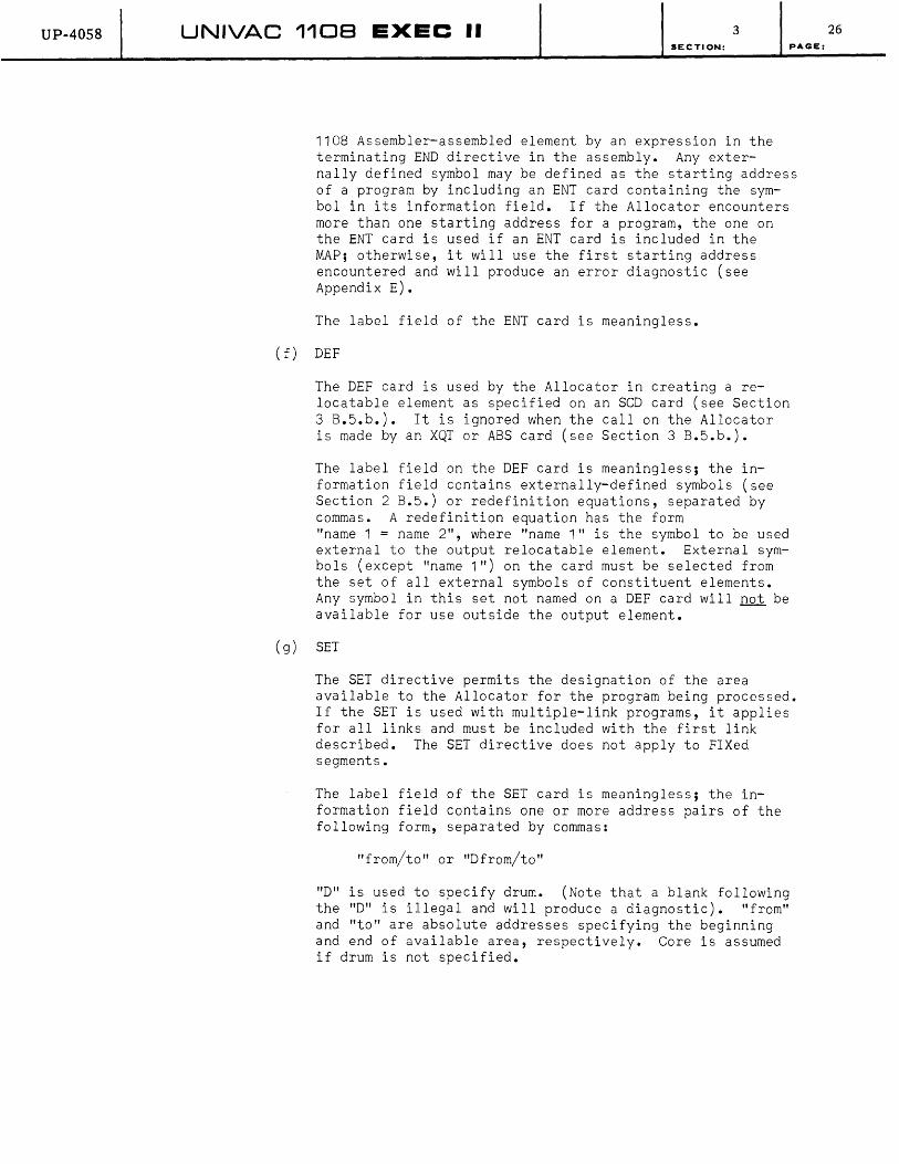
UP-4058 UNIVAC 1108 EXEC II 3 SECTION: PAc;E:
1108 Assembler-assembled element by an expression in the terminating END directive in the assembly. Any externally defined symbol may be defined as the starting address of a program by including an ENT card containing the symbol in its information field. If the Allocator encounters more than one starting address for a program, the one on the ENT card is used if an ENT card is included in the MAP; otherwise, it will use the first starting address encountered and will produce an error diagnostic (see Appendix E).
The label field of the ENT card is meaningless.
(f) DEF
The DEF card is used by the Allocator in creating a relocatable element as specified on an SCD card (see Section 3 B.5.b.). It is ignored when the calIon the Allocator is made by an XQT or ABS card (see Section 3 B.5.b.).
The label field on the DEF card is meaningless; the information field contains externally-defined symbols (see Section 2 B.5.) or redefinition equations, separated by commas. A redefinition equation has the form "name 1 = name 2", where "name 1" is the symbol to be used external to the output relocatable element. External symbols (except "name 1") on the card must be selected from the set of all external symbols of constituent elements. Any symbol in this set not named on a DEF card will not be available for use outside the output element.
(g) SET
The SET directive permits the designation of the area available to the Allocator for the program being processed. If the SET is used with multiple-link programs, it applies for all links and must be included with the first link described. The SET directive does not apply to FIXed segments.
The label field of the SET card is meaningless; the information field contains one or more address pairs of the following form, separated by commas:
"from/to" or "Dfrom/to"
"D" is used to specify drum. (Note that a blank following the "D" is illegal and will produce a diagnostic). "from" and "to" are absolute addresses specifying the beginning and end of available area, respectively. Core is assumed if drum is not specified.
26

UP-4058 UNIVAC 1108 EXEC II SECTION:
As many SET cards as needed may be used; the areas specified are cumulative.
(h) FIX
3 PAGE:
The FIX directive permits specification of the core location to be used as the beginning of a segment. Any segment may be fixed which is not wholly included in an overlay (i.e., subsegments may not be fixed). The label field on the FIX card is meaningless, while the information field has the following form:
name, bank 1, bank 2, drum
"Name" is the name of the segment to be fixed. The other three subfields designate the absolute core address to be used as the initial location of the segment in bank 1, bank 2 or drum. Any address may be omitted, in which case the Allocator will choose it. The commas must be present in the card to define the fields. It is the responsibility of the user to insure against impossible assignments resulting from the use of a FIX directive.
b. XQT, ABS, SCD Control Cards
XQT, ABS and SCD cards are control cards used to call the Allocator. They contain an options field (see Appendix C 2.), a flag field, and a name field. The SCD card causes the Allocator to create a relocatable element (sometimes called a sub-complex, since it normally is produced from more than one element) in which no external references (see Section 2 B.5.) exist. The ABS card causes the Allocator to create an absolute element. The output element in both of the above cases will be stored in the User's PCF (see Sections 2 B.5. and 3 B.6.). The XQT card calls for a program to be executed; if necessary, the Allocator will first create an absolute element, as is done for the ABS card. The card fields are described below. (See Section 3 B.5.c. for description of Allocator operation.)
(1) Options field
This field contains a group of alphabetic characters used to specify special handling by the Allocator (see Appendix C 2.). It must be selected from the set (A,C,E,K,L,M,N,P,T,V,W,X,Y,Z) except that "E", "L", and "Z" may not be used on the SCD card, and "P" may be used only on the SCD card. "K" and "V" may be used only on the ABS card.
(2) Flag field
This field contains a single alphabetic character. It is used by the Allocator to resolve ambiguities in selecting elements to be included in allocation (see Section 3 B.5.c.).
27

UP-4058 UNIVAC 1108 EXEC II 3 SECTION:
(3) Name field
This field contains a pair of labels separated by a slash (/). Each label contains up to six characters (A-Z, 0-9, +, ., $), the first of which must be alphabetic (A-Z) and represents the name and version respectively of a relocatable element or a processed MAP. In the XQT card only, it may also refer to an absolute element. The version field may be omitted (in which case the slash must also be omitted); however, this 'omission will result in an ambiguity if more than one element in the User PCF has the given name. In ABS and SCD cards, the name field may contain a second pair of labels as described above, separated from the first pair by a comma. These labels are
PAGE:
used as the name and version respectively of the output element.
System Response to SCD card
When CCI (see Section 2 B.1.) encounters an SeD control card, it places it in the print file and stores parameters from the card in PARTBL, a parameter table in COMMUN (see Section 2 A.). If punch output is called for, an ELT card (see Section 3 B.6.a.) is created for the output relocatable element. The Allocator is then loaded by CCIRES (see Section 2 A.) as a worker program (see Section 4 A.2.) and produces the required relocatable elem&nt ("subcomplex") and print or punch output according to the options field. After completion CCIRES is re-entered, where a check is made for error options if errors occured, in which case the message
"ERRS IN ELEMENT PRODUCED"
is placed in the print file. CCI is then reloaded to insert the relocatable element in the User PCF (see Section 2 B.5.) provided it is error-free or an option to ignore errors has been exercised, and to continue by reading another control card.
System Response to ABS card
The ABS card is handled similarly to the SCD card with the following exceptions:
(1) No punch option is available.
(2) The output is an absolute element rather than a relocatable element.
System Response to XQT card
The XQT card is handled similarly to the SCD card with the following exceptions:
(1) No punch option is available.
(2) Checks are made on the name field to determine whether the following special programs are being called for;
(a) CUR
(b) ICS
(see Section 3 B.6.c.)
(see Section 3 B.9.a.)
(c) LIBRY (see Section 3 B.7.)
28

UP-40S8 UNIVAC 1108 EXEC II 3
c.
SECTION:
(3) No output is produced if the input is an absolute element; otherwise, an absolute element which is not entered in the User PCF is produced.
( 4) When the Allocator exits, LOAD is entered (see Section 2 A.) load and execute the program specified, as a worker program ( see Section 4 B.). CCIRES is re-entered upon program termination.
The Allocator
to
The Allocator is an element manipulative processor, i.e., a special program which collects program elements (see Section 3 B.6.) and interconnects them. Cross-references between elements are resolved and relative locations assigned. Depending on how the Allocator is called, it may go on to produce an absolute program stored in the User's PCF (see Sections 2 B.5. and 3 B.6.). Finally, this absolute program may be loaded into core and run.
The Allocator will also, unless requested otherwise, construct a
PAGE:
group of tables which serves as one of the inputs to the diagnostic system (see Sections 3 B.9. and 4 B.3.). In order to provide flexible and sophisticated segmentation ability, an auxiliary processor called the Memory Allocation Processor is provided (see Section 3 B.5.a.) which produces an allocation plan with which the Allocator works. In the absence of this plan, called a "MAP", the Allocator produces a "reasonable" output assuming that all elements are to occupy core simultaneously.
Three separate control cards result in calling the Allocator (see Section 3 B.5.b.) to cause it to perform the functions described above.
To comprehend the operation of the Allocator, Sections 3 B.5.a.(MAP) and 2 B.5. (Elements, User peF) should be fully understood.
ALLOCATOR Operation
(1) The name field of the calling control card (XQT, SCD, ABS) is used to locate an element by searching the User PCF (see Section 3 B.6.). Only relocatable and MAP elements are considered except in the case of the XQT card which causes absolute elements to be considered. If no element is found with the name specified on the calling control card, the Library PCF (see Sections 2 B.3. and 3 B.7.) is similarly searched. If no element is located there, an error is indicated and the allocation is aborted. If more than one element with the given name is found, the Allocator uses selection rules (see paragraph 4, below) to choose a single one; if the selection rules do not define a single element, an error is indicated and the Allocator selects an element arbitrarily. Once exactly one element is chosen, the Allocator determines whether it is a relocatable element, a MAP, or (in the case of the XQT card call) an absolute element; if it is an absolute element, the Allocator takes the system normal exit (see Section 4 C.). If it is a relocatable element, it must be included in the output element.
29

UP-4058 UNIVAC 1108 EXEC II 3 SECTION:
(2) If the located element was a MAP, it is used to search the User's PCF for relocatable elements; if the User's PCF does not contain the element sought, the Library PCF is searched. If an element sought is not found, it is deleted from the allocation process, an error is indicated, and allocation continues. The relocatable elements sought are defined by SEG cards; any segment or subsegment specified in the information field of a SEG card which is not defined on the label field of another SEG card is assumed to be a relocatable element. If any such search causes more than one element to be found which has the name specified on the SEG card, the selection rules (see paragraph 4 below) are used to define a single element; if this procedure fails to define exactly one element, an arbitrary element is chosen and an error is indicated. Each relocatable element chosen will be included in the output element.
(3) For every relocatable element which the Allocator is to include in the output element, a table of undefined symbols (see Section 2 B.5.) is built. Every symbol in this table is used as a key to search the Entry Point Table (see Section 2 B.5.) in the User's PCF; if the symbol is not matched in the User's PCF Entry Point Table, the Library PCF Entry Point Table is similarly searched. If the symbol is found, every element defining the symbol (as indicated in the Entry Point Table) is considered. If the symbol is not defined by the Entry Point Table, the relocatable element names themselves are searched and if a match occurs, each element with the given name is considered. If the input element was a MAP, the label fields of SEG cards are also searched for a match against the symbol. If the symbol is defined by at least one element and by a SEG card, the Allocator considers that no definition has been found. If more than one element defines the symbol (and no SEG card defines it), the selection rules are used to determine the single element required (see paragraph 4 below). If the selection rules do not define exactly one element, the Allocator considers that no definition has been found. If no definition is found for the symbol (either a "no-find" condition, or ambiguity as outlined above), an error is indicated and the symbol remains undefined. If a definition is established by a relocatable element, that element will be included in the output element. The procedures described in this paragraph are continued until every symbol has a definition (either as an entry point or as the name of a segment or element) or is noted as a "no-definition" error.
(4) The selection rules for resolving ambiguities as indicated in previous paragraphs are as follows:
(a) If one of the elements under consideration has already been chosen for inclusion in the output element, that element is used (if more than one such element exists, one is used arbitrarily with no error indication given).
(b) If the MAP being utilized by the Allocator contains a USE card which specifies the name and version of exactly one of the elements under consideration, that element is chosen to be included in the output element.
30 PAGE:

UP-40S8 UNIVAC 110B EXEC II 3 SECTION:
(c) If a flag is specified on the calling control card and if exactly one of the elements has a flag in which the letter of the control card flag appears, that element is chosen for inclusion in the output element.
PAGE:
(5) Once all the constituent elements have been chosen, the Allocator proceeds to combine them into a single relocatable element. If no MAP is provided, a single link is assumed, all segments of which are independent, and common areas are defined by group number (see BLK directive for details). If a MAP is provided, its directives are followed to modify the above assumption.
The size of "blank common" is determined by taking the largest reference to it in any link. The size of "labeled common" is determined by taking the largest reference to it in the link in which it is to be allocated. The sequence of allocating independent segments within a link is arbitrary, usually in the order in which elements were chosen. An independent segment is allocated by determining the total core and drum area required for each location counter declared in the segment. The base relocatable address for each such counter is initially zero, and is incremented by the amount allocated to it for each independent segment. Every symbol in the segment is assigned to a relocatable address, relative to its location counter. All references to such a symbol are equated to its relocatable address.
If any references to undefined symbols remain in the segment, these are equated to zero and remain undefined (an error has been indicated). Every independent segment in the link is thus allocated.
When the entire link has been built, the starting symbol is so marked. The starting symbol is determined by the specification on an ENT card or by the specifications in constituent elements if no ENT card is supplied. If no constituent contains a starting symbol indication and no ENT card is supplied, no starting symbol is designated, and an error is indicated. If the ENT card contains a symbol not defined in the link, the same action is taken. If more than one starting symbol indication exists in the constituents, the first is designated as the starting symbol, and an error is indicated. When every link has been allocated and starting symbols designated, the relocatable output element is complete. All "patches" (see paragraph 7) included with the input to the Allocator are inserted. If the calling control card was SCD, the Allocator determines whether any DEF card was supplied with the MAP specified (if a MAP was specified). If so, all symbols listed on the DEF card are marked as external references and included in the Entry Point Table for the output element. If SCD was the calling control card, the Allocator exits at this point.
31

UP-4058 UNIVAC 1108 EXEC II 3 SECTION;
(6) Once the relocatable form of the output element is complete the Allocator may build an absolute element. To do this, in the absence of a MAP, the assumption is made that all worker program areas in core and drum (see Section 2 C.) are available and makes no provision for FIXing the absolute location of any element. If a MAP was provided, the specifications of SET and FIX cards modify these assumptions.
PAGE;
Each location counter used in the first link is given a value corresponding to an absolute memory location in the available areas in core or drum, as required. The absolute assignment leaves exactly enough room for information included und~r preceding location counters in the same area (bank 1, bank 2 or drum), and enough space must be available after the last such assignment for all remaining information to fit. (If not, an error exists and the Allocator aborts.) The relocatable address addresses assigned in creating the relocatable element are modified by adding the value of the location counter to the relocatable address. This is called "relocation" and results in absolute memory assignments consistent throughout the link. All location counters are then re-initialized and the next link is allocated. When all links have been processed, an absolute program exists and allocation ends.
In this process, information is associated with the absolute element to designate to the diagnostic system and to the loader such specifications as:
(a) Where the "starting symbol" is, in absolute form
(b) Where each segment in the program is, in absolute form.
(c) Which areas are "labeled common" or blank common" areas. ,
(d) What information is to be loaded into a common area initially, and under what circumstances, if any, it is to be re-initialized.
The above listing is not exhaustive; however, it indicates the kind of information with which the loader and diagnostic system work.
(7) Patches
The Allocator contains prOV1Slon for relocatable "patches" to be entered when an absolute program is to be built. A "C" option letter on the calling control card indicates that patches are to be made. Each patch may be relocated according to information on the card and will overlay the location specified on the card when the absolute program is built. Patch cards should appear in the RUN deck following the control card which calls the Allocator. They should be segregated by EOF cards (see Section 3 B.3.a.) into groups for each program link, with each group terminated by an EOF card. Links which are not to be patched must have an EOF card in the patch deck to keep the Allocator synchronized with the deck. If a given location is patched twice, the last patch will be used. Approximately 100 patches will be accepted by the Allocator. The format of patch cards follows.
32

UP-4058 UNIVAC 1108 EXEC II 3 SECTION:
(a) Element Name Header: This card should precede all patches for the element.
Starting in Col 1.
Next column after name/version
Columns following comma
Element Name/version
Comma (,)
*Location counter
(b) Instruction patches (all fields except location counter are octal). Also refer to 1108 Processor and Storage Manual for interpretation of instruction fields.
Columns 1-6
Columns 9-12
Columns 14-15
Columns 17-18
Column 20
Columns 22-27
Columns 29-31
(c) Data patches (all fields octal).
Columns 1-6
Columns 9-20
Columns 22-24
Columns 26-28
Relocatable location
Function code and j-designator
A-register
X-register
h-indicator (indirect, increment)
u-field (operand)
*Location counter (bits 0-15)
except location counter are
Relocatable location
Data
*Location counter (bits 0-15 or 18-33)
*Location counter (bits 0-15)
PAGE:
*The "Location Counter" is a programmed specification of the relative starting point of a section of code. Relocation is accomplished with respect to a given location counter as a base. In the "Element Name Header" card (paragraph a) the Location counter is the base for relocating the location field in "Instruction" and "Data" ,cards (paragraph b and c). In the "Instruction" card, the Location counter is the base for relocating the "u-field". In the "Data" card, two location counters are used, the first for relocating bits 18-33 and the second for relocating bits 0-15. If only one is used, bits 0-15 are relocated relative to this base. Location counters are specified as one, two or three digit integers, the first of which must be zero if an octal number is desired. If the field is blank, no Location ~ounter is specified and relocation does not occur.
In "Instruction" and "Data" cards, the Location counter may also be specified as "Element name, Location counter number" in order to use a base specified in a different element. In this case, the fields shown for location counter will be enlarged as required and will be terminated by a blank.
33
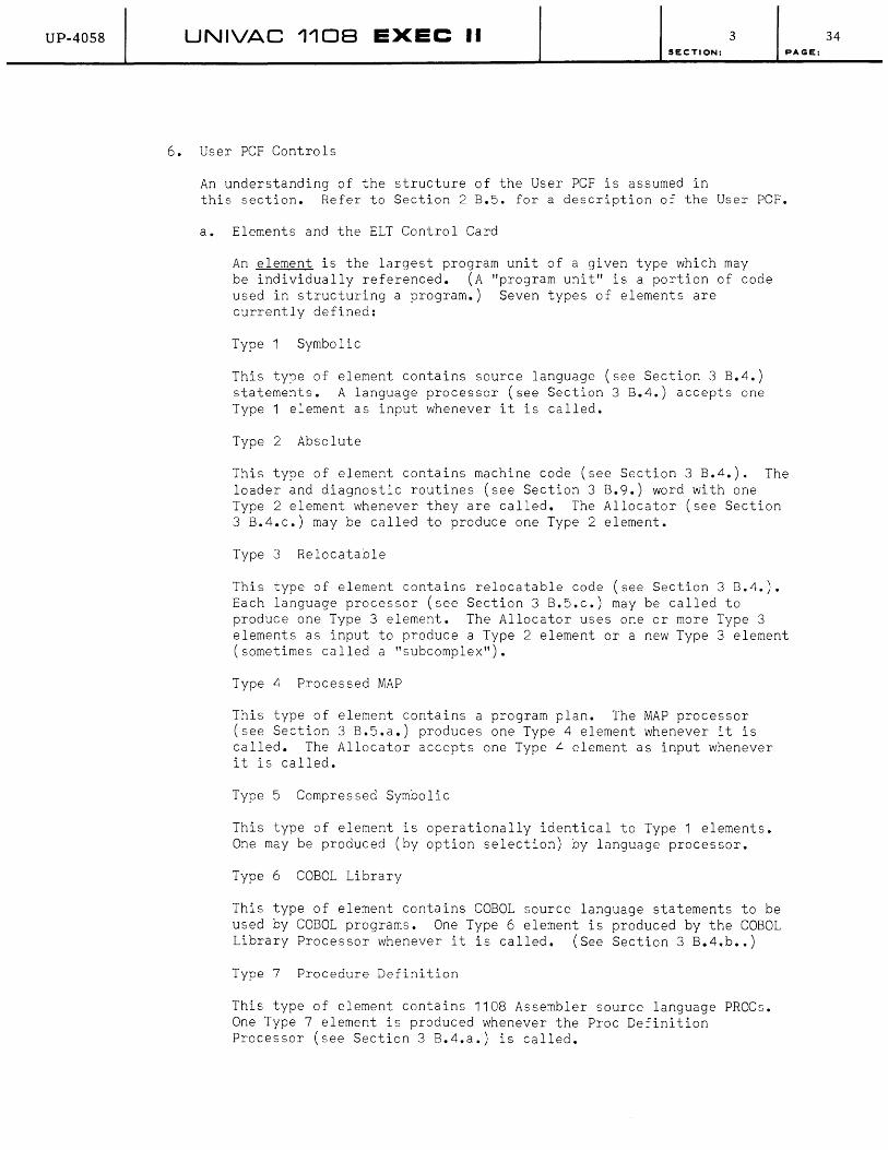
UP-40S8 UNIVAC 1108 EXEC II 3 SECTION: PAGE:
6. User PCF Controls
An understanding of the structure of the User PCF is assumed in this section. Refer to Section 2 B.5. for a description of the User peF.
a. Elements and the ELT Control Card
An element is the largest program unit of a given type which may be individually referenced. (A "program unit" is a portion of code used in structuring a program.) Seven types of elements are currently defined:
Type Symbolic
This type of element contains source language (see Section 3 B.4.) statements. A language processor (see Section 3 8.4.) accepts one Type element as input whenever it is called.
Type 2 Absolute
This type of element contains machine code (see Section 3 8.4.). The loader and diagnostic routines (see Section 3 B.9.) word with one Type 2 element whenever they are called. The Allocator (see Section 3 B.4.c.) may be called to produce one Type 2 element.
Type 3 Relocatable
This type of element contains relocatable code (see Section 3 8.4.). Each language processor (see Section 3 B.5.c.) may be called to produce one Type 3 element. The Allocator uses one or more Type 3 elements as input to produce a Type 2 element or a new Type 3 element (sometimes called a "subcomplex").
Type 4 Processed MAP
This type of element contains a program plan. The MAP processor (see Section 3 B.5.a.) produces one Type 4 element whenever it is called. The Allocator accepts one Type 4 element as input whenever it is called.
Type 5 Compressed Symbolic
This type of element is operationally identical to Type 1 elements. One may be produced (by option selection) by language processor.
Type 6 COBOL Library
This type of element contains COBOL source language statements to be used by COBOL programs. One Type 6 element is produced by the COBOL Library Processor whenever it is called. (See Section 3 B.4.b •• )
Type 7 Procedure Definition
This type of element contains 1108 Assembler source language PROCs. One Type 7 element is produced whenever the Proc Definition Processor (see Section 3 B.4.a.) is called.
34

UP-4058 UNIVAC 1108 EXEC II 3 SECTION:
Every element is identified by its name which is a string of characters (A-Z, 0-9, +, ,$) beginning with an alphabetic (A-Z). To permit several elements with the same name to be in the PCF, each element is also identified by its version which is a secondary name similar in form to the name as described above. When no ambiguity is introduced by so doing, an element is referenced by name; to avoid ambiguity the reference should be "name/version". For even greater capability in identifying an element, a il£g may be associated with it. This is a string of alphabetic characters (A-Z) which is retained in the following manner as a 26 bit switch: every letter in the alphabet is associated with a bit in the switch; when the bit contains a zero, the letter is absent in the flag; when the bit contains a one, the letter is present in the flag. This permits a given element to be updated while retaining its original form for use while the update is being checked out.
Elements are manipulated or produced by the language processors (see Section 3 B.6.b.), the Allocator (see Section 3 B.6.b.), the ELT card, described in this section, or by CUR (see Section 3 B.6.c.). Each of these causes elements to be inserted or deleted in the User PCF.
Whenever an element is inserted into the User PCF, a check is made to determine whether its name and version duplicate the name and version of an element already in the PCF. If so, the old element is deleted, i.e., marked as unavailable for use. An element without a version specified is different from one with a version even if their names are identical.
Each type of element is composed of "pieces" (see Section 2 B.S. for description of the structure of elements on drum). Whenever an element is input to or output from the User PCF, these pieces must be separated by EOF cards (see Section 3 B.3.a.). Column 7 of the EOF card preceding the piece contains a descriptor number corresponding to the piece, which specifies the sequence in which the pieces are punched (or written on tape). The EOF card may be omitted for a Type 1 (symbolic) element, since only one piece is specified for this type.
ELT control card
The ELT card is a control card used to input an element into the User PCF from a card file. It is produced whenever elements are punched on cards from the User PCF. It is identified by the word ELT in the card name field, and contains a name field, a type field, a date field and a time field separated by commas. These fields are described below:
Name: This field, the only essential one other than the card name, contains the name and version of the element, separated by a slash (/), and the flag associated with the element enclosed in parentheses. (See paragraph 1 of this section for a description of name, version, flag.)
35 PAGE:

UP-4058 U.NIVAC 1'108 EXEC II 3 SECTION:
Type: This field contains a single integer (1-7) specifying the element type, as indicated in paragraph 1 of this section. If omitted, type 1 is assumed.
Date: This field is a six-digit decimal integer of the form "yymmdd" (year, month, day). It and the time field together a~e stored in the PCF to indicate when the element was created or last altered. If data is omitted, the current date will be stored when the element is inserted into the PCF.
Time: This field, stored as is the Date field, contains the time corresponding to creation or last alteration of the element as a decimal integer (0-86400) specifying the number of seconds from midnight. If omitted, the current time will be stored when the element is inserted in the PCF.
System Response to ELT card
When CCI encounters an ELT card, it places the card into the output file and determines that room exists in the User PCF area on drum for an element to be inserted. (Since the size of the element is not known, this determination may be overruled later if the element is found to be too large.) The CCI reads the Table of Contents of the User PCF into core, and proceeds to load CUR (see Section
PAGE:
3 B.5.c.) as a worker program (see Section 4 A.2.). CUR transfers the element found on card images following the ELT card into the User PCF, and re-enters CCI to read another control card. Note that (except for symbolic elements) CUR requires EOF cards (see Section 3 B.3.a.) preceding each "piece" of the element.
b. Language Processor and Allocator Outputs
The Language Processors (see Section 3 B.4.) and the Allocator and Memory Allocation Processor (see Section 3 B.5.) produce output in the form of elements. (See Section 3 B.6.a •• ) This output is normally placed in the User PCF'(see Section 2 B.5.) and may be punched or printed by programmer specification. The following table shows . the type number of elements (see Section 3 B.6.a.) produced by the processors into the PCF; for optional output, see Appendix C 2. and the sections dealing with the various processors (as indicated above).
36

UP-4058 UNIVAC 1108 EXEC II 3 SECTION:
Processor Into User PCF PUNCH** PRINT***
1108 Assembler Type 3· , 1* 3,5 1 ,3
PROC Definition Processor Type 7 5,7 7
COBOL Compiler Type 3· , 1* 3,5 1 ,3
COBOL Library Processor Type 6 5,6 6
FORTRAN Compiler Type 3· , 1* 3,5 1 ,3
LIFT Processor Type 1 1,5 1
Allocator Type 2 or 3 2 3****
Memory Allocation Processor Type 4 4,5 4
* For the indicated cases. Type 1 elements are produced only when output source names are specified. Type 5 elements are not placed in the User PCF, except by ELT card input handling (see Section 3 B.6.a.).
** Punch output is produced when specified in the options field of the calling control card. (See Appendix C.2 •• )
*** Print output is controlled by options specifications (see Appendix C 2.).
PAGE:
**** Allocator print output consists of the absolute areas assigned to elements, by control counter, and may include a list of symbols defined in the elements. In no case is a detailed listing of all locations of an absolute element produced. Note also that the Allocator produces no output when the input is an absolute element and the call is made by an XQT card.
c. CUR (Complex Utility Routines)
CUR is an element manipulative processor, i.e., it is a special program which manipulates elements in the User PCF. It is called by means of an XQT control card with the name "CUR" in the name field. It operates by means of pseudo-instructions punched on cards following the "XQT CUR" card. While operating, it produces a printed listing of the pseudo-instructions and any special or error conditions which may arise. (See Section 6 for diagnostic messages.)
CUR Pseudo-instruction cards are free-form, i.e., the fields are not defined by specific card columns. Each card contains a pseudodirective and an information field. The pseudo-directives are listed below and explained in succeeding paragraphs. If an error is indicated while CUR is operating, all following operations are listed but not performed, and CUR exits via the system abort exit (see Section 4 C.). The format' of the CUR pseudo-instruction card requires only that the pseudo-directive be separated by a blank from the information field which follows it; otherwise any columns may be used for either. (See Appendix D 4. for the tape format of program files.)
37

UP-4058 UNIVAC 1108 EXEC II 3 SECTION:
CUR Pseudo-Directives (alphabetic order)
DEL Mark element in User PCF deleted.
* (See Input elements from cards below.)
ERS Erase the entire User PCF.
FIND Locate element in tape file.
FLG Alter the flag of an element.
IN Input the entire User PCF from tape.
LIST List element on printer.
OUT Output the entire User PCF to tape.
PCH Output element on card punch.
PAC Make space occupied by deleted elements available.
PEF Position tape to end-of-file.
TEF Write end-of-file on tape.
TOC List the Table of Contents on Printer.
TRD Input element from tape.
TRI Rewind tape with interlock.
TWR Output element to tape.
VER Alter version of element.
* Card input is accomplished by means of the ELT control card (see Section 3 8.6.a.). No pseudo-directive is provided to perform this function.
Pseudo-Directive Information field Operation
PAGE:
(1) DEL NAME/VERSION Delete element, NAME/VERSION, from the User PCF. If the element has no VERSION, the field should contain NAME only. Note: Deleting does not cause the space occupied by the element to be made available.
(2) ERS not used Erase the entire contents of the User PCF; all drum space designated as User PCF is thus made available.
38
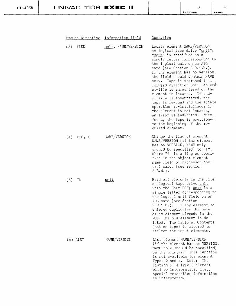
UP-4058 UNIVAC 1108 EXEC II
Pseudo-Directive Information field
(3) FIND unit, NAME/VERSION
(4) FLG, f NAME/VERSION
(5) IN
(6) LI ST NAME/VERSION
3 SECTION: PAGE:
Operation
Locate element NAME/VERSION on logical tape drive·"unit"; "unit" is specified as a single letter corresponding to the logical unit on an ASG card (see Section 3 B.1.b.). If the element has no version, the field should contain NAME only. Tape is searched in a forward direction until an endof-file is encountered or the element is located. If endof-file is encountered, the tape is rewound and the locate operation re-initialized; if the element is not located, an error is indicated. When found, the tape is positioned to the beginning of the required element.
Change the flag of element NAME/VERSION (if the element has no VERSION, NAME only should be specified) to "f", where "f" is a flag as specified in the object element name field of processor control cards (see Section 3 B.4.).
Read all elements in the file on logical tape drive unit into the User PCF; unit is a single letter corresponding to the logical unit field on an ASG card (see Section 3 B.1.b.). If any element so entered duplicates the name of an element already in the PCF, the old element is deleted. The Table of Contents (not on tape) is altered to reflect the input elements.
List element NAME/VERSION (if the element has no VERSION, NAME only should be specified) on the printer. This function is not available for element Types 2 and 4. Note: The listing of a Type 3 element will be interpretive, i.e., special relocation information is interpreted.
39
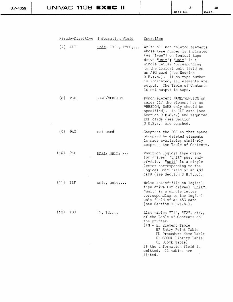
UP-4058 UNIVAC 1108 EXEC II 3 SECTION: PAGE:
Pseudo-Directive Information field Operation
(7) OUT
(8) PCH
(9) PAC
(10) PEF
(11) TEF
(12) TOC
unit, TYPE, TYPE, ••• Write all non-deleted elements whose type number is indicated (as "type") on logical tape drive "unit"; "unit" is a single letter corresponding
NAME/VERSION
not used
unit, unit, •••
unit, unit, •••
T1, T2, •••
to the logical unit field on an ASG card (see Section 3 B.1.b.). If no type number is indicated, all elements are output. The Table of Contents is not output to tape.
Punch element NAME/VERSION on cards (if the element has no VERSION, NAME only should be specified). An ELT card (see Section 3 B.6.a.) and required EOF cards (see Section 3 B.3.a.) are punched.
Compress the PCF so that space occupied by deleted elements is made available; similarly compress the Table of Contents.
Position logical tape drive (or drives) "unit" past endof-file. "unit" is a single letter corresponding to the logical unit field of an ASG card (see Section 3 B.1.b.).
Write end-of-file on logical tape drive (or drives) "unit". "unit" is a single letter corresponding to the logical unit field of an ASG card (see Section 3 B.1.b.).
List tables "T1", "T2", etc., of the Table of Contents on the printer. (TN = EL Element Table
EP Entry Point Table PN Procedure Name Table CL COBOL Library Table BL Block Table)
If the information field is omitted, all tables are listed.
40

UP-4058 UNIVAC 1108 EXEC II
Pseudo-Directive Information
(13) TRD
(14) TRI unit, unit, •••
(15) TRW
(16) TWR unit, NAME/VERSION
(17) VER NAME/ORIG, NEW
3 SECTION: PA(;E:
Operation
Read one element from logical tape drive "unit" into the PCF (if this element has a name which duplicates that of an element already in the PCF, the old element is deleted) • "unit" is a single letter corresponding to the logical unit field of an ASG card (see Section 3 B.1.b.).
Rewind logical tape drive (or drives) "unit" and interlock them against further operation. "unit" is a single letter corresponding to the logical unit field of an ASG card (see Section 3 B.1.b.).
Similar to the previous pseudo-instruction, except that the rewound drive (or drives) is not interlocked.
Write element NAME/VERSION (if the element has no VERSION, NAME only should be specified) on logical tape drive "unit". "unit" is a single letter corresponding to the logical unit field of an ASG card (see Section 3B.1.b.).
Change the VERSION of element NAME/ORIG to NEW. If NEW is omitted the VERSION is eliminated. If this causes duplication of the name of another element in the PCF, the other element is deleted.
If, while performing any operation, the User PCF area on the drum is exceeded, an error is indicated. If any card is malformed in any way, or if any element is malformed, an error is indicated.
After all CUR operations have been performed, the updated Table of Contents is rewritten on the drum.
41
UP-4058 UNIVAC 1108 EXEC II 3 SECTION:
7. LIBRARY Control: LBR Control Card (XQT LIBRY)
In addition to the User PCF, a special complex is provided called the system library. The structure of the system library is similar to the User PCF (see Section 2 B.3.). Elements may be called from the library (whenever a search does not locate a given element in the User PCF) , but may not be entered into the library individually. The only method of changing a system library is to create a complete library complex in the User PCF and transfer it, as described below, into the Library PCF.
The LBR is a control card used to call for a system routine to transfer the User PCF in toto to the Library PCF. Alternatively, this routine
PAGE:
may be called by an XQT card with the name "LIBRY" in the name field. No other fields are defined for either calling control card.
System Response to the LBR (XQT LIBRY) card:
When CCI encounters an LBR (or XQT LIBRY) card, it places it in the print file and calls the element "LIBRY" to transfer the User PCF to the Library PCF, after which CCI is re-entered to read another control card. It is suggested that deleted elements and symbolic elements be removed from the User PCF before LIBRY is called.
B. System Generation: XQT RSDNT
The complete EXEC II system is described in Sections 2 A. and 2 B.. When a system tape is prepared, it must contain the resident and drum portions of EXEC in absolute form, all processors in absolute form, and all library elements in relocatable or absolute form, as required. Assuming that these are already loaded into core and drum, a system routine (in relocatable form, which is entered into the User PCF) is provided for creating the system tape. This routine is called "RSDNT" with a version indicative of the EXEC size of the system to be built. To call the tape-creating routine (for an BK EXEC system), an XQT control card (see Section 3 B.5.b.), with the name "RSDNT/v65 or "RSDNT/v32" in its name field must be used. ("RSDNT/v12" may also be used to create a 12K EXEC system in 65K of Core.)
Technique
The EXEC II system is generated and maintained by UNIVAC systems Programming. Any user alteration in it is normally the responsibility of the user. However, it is recommended that a "backup" system tape be created whenever a new system shipment is received. "RSDNT" provides the capability of system tape copying. To copy a tape, it should be "bootstrapped" (see 110B EXEC II Operator's Reference Manual), the resident routines supplied on the tape must be entered into the User PCF (see Section 3 B.6.), and a RUN Deck calling for "RSDNT" should be entered. If any changes are to be made in the library, these must be done prior to the calIon "RSDNT" (see Section 3 B.7.). Note that the resident routines in relocatable format are currently placed in the fourth file of systems tapes supplied by UNIVAC.
42
UP-40S8 UNIVAC 1108 EXEC II 3 SECTION:
9. Diagnostic Routines: Debug Control
The EXEC II system contains a system of diagnostic routines available to the user for debugging programs. These routines are divided into two distinct groups:
1. Independent diagnostic programs
2. Dependent diagnostic subroutines
PAGE:
The second of these groups is discussed in Section 4 B.3 •• The following three sections will outline diagnostic routines which are essentially independent of the user's program. Actually, ICS, the first of the independent routines discussed, contains dumping routines which are accessible to a user program in operation; however, since ICS is a control routine, called independently, it is discussed here. The post-mortem dump and panic dump capabilities covered in the latter two of the next three sections are fully independent of any user program, since they operate after a program under checkout has terminated.
a. ICS: ICS Control Card (XQT ICS)
ICS (abbreviation for Initial Checkout System) is a simple control routine which may be used for utility and checkout purposes. It is called by either an XQT card (see Section 4 B.5.b.) with the name "ICS" in the name field, or an ICS card, which is a control card containing the word ICS in the card name field. The ICS card has no options and no other field on it; it is responded to by the system exactly as the "XQT ICS" card is. Many of the functions of ICS have been replaced by more sophisticated techniques; however, ICS may be utilized whenever it is appropriate. A description of ICS follows. (1108 Hardware manuals should be consulted as needed for clarification of hardware references in this section.)
Operation of ICS:
When ICS is turned on, it reads cards of a special format, and performs operations as specified on the cards. All ICS operations deal with absolute machine addresses which are not checked by ICS; the system is easily violated, and caution in its use is recommended. If ICS is to be used during the operation of a user program, a special system calling sequence is necessary to turn it on (see Section 4 B.3.). ICS itself has the capability of jumping back to the user program if the absolute location of the return point is specified. The system may also be used for set-up or post-mortem checkout capabilities with the call as mentioned in the definition paragraph.
Certain operations may be specified to ICS on the cards which follow the calling control card. The format of these cards is fixed, with operations determined by the position of blank columns in the card. Only columns 1 through 32 of the card (except the multiple-word load card) are used. Unused columns may contain user's comments or may be left blank. The following table summarizes the ICS cards. Interpretation of specific fields are discussed in the following paragraphs.
43

UP-4058 UNIVAC 1108 EXEC II 3 SECTION:
Note that all twelve of the operations originally designed into Ies are included in the table. However, these are currently divided into three sets:
(1) Obsolete operations (numbers 4-7 on table). Tape and drum write operations have been deleted from ICS in latest versions of EXEC 11.
(2) Remote system operations (none available). Internal dump operations are the only ICS operations available in such systems (see Section 4 B.3.f.).
(3) Non-remote system operations (numbers 1-3, 8-12 on table). All operations which are not obsolete (1, above) are available in systems without remote capability.
PAGE:
Any call to rcs (in a system in which rcs is not provided, such as 2, above, will result in the printout "NO rcs", and the job will be aborted (termination via MXXX$, see Section 4 C.).
44

ICS CARD FORMATS
'. CARD COLUMNS
OPERATION 123 456 7 8 9 10 11 12 13 14 15 16 17 18 19 20 21 22 23 24 25 26 27 28 .....
1 MEMORY PRINT R F F F F F F T T T T T T
2 JUMP J J J J J J
3 DRUM READ D D D D D D D D
4 DRUM WRITE* D D D D D D D D T T T T T T T T
5 TAPE REWIND* U
6 TAPE READ* U F F F F F F
7 TAPE WRITE* U F F F F F F T T T T T T
8 SNAPSHOT L L L L L L R F F F F F F T T T T T T
9 MEMORY CLEAR F F F F F F T T T T T T
10 INSTRUCTION LOAD L L L L L L F F J J A A B B H U U U U U U
11 WORD LOAD L L L L L L W W W W W W W W W W W W
12 MULTI-WORD LOAD L L L L L L NW W W W W W W W W W W W (words 2-6 are each 12
characters beginning in the next available column).
* Obsolete. Not included in latest versions of EXEC II.
Note: Blank columns indicated are required for proper interpretation of the card. Each field must be filled with non-blank characters as indicated (including leading zeros). "R" in cards 1 and 8 is a single digit (0, 1, 2, 3, 4, 5, 6, 7) interpreted as register groups, as follows:
R = 0 NO REGISTERS 1 R-registers 2 A-registers 3 A-registers and R-registers 4 B-registers 5 B-registers and R-registers 6 B-registers and A-registers 7 B-reqisters and A-reqisters and R-registers
.. 11\ n ~ o z
'11
• " 11\
c:: '1j I ~ o CJ1 00
c z ~ (]
~ ~
o m m )( m n --

UP-4058 UNIVAC 1108 EXEC II 3 SECTION:
(1) Memory Print
"R" designates the register groups to be printed. "FFFFFF" and "TTTTTT" represent, in octal notation, the lower and upper core limits respectively of the memory area to be printed as soon as this card is interpreted.
(2) Jump
"LLLLLL" designates the core location, in octal notation, to which control is to be transferred. The jump is made as soon as this card is interpreted, with all registers and the carry and overflow indicators reset to the values they had when ICS was entered.
(3) Drum Read
"DDDDDDDD" designates the drum address from which the access
PAGE:
word is to be read. The read operation continues, according to the access word, from the following drum address. This operation is performed as soon as the card is interpreted.
( 4) Drum Wri te
"DDDDDDDD" designates the drum location to which the access word is to be written; this is followed by all words between core locations "FFFFFF" and "TTTTTT" inclusive (locations in octal notation) written to the area on drum starting with the location following the access word. The access word is constructed by ICS, and contains the number of words transferred in the high-order 18 bits, and the address "FFFFFF" in the loworder 18 bits. This operation is performed as soon as the card is interpreted. (obsolete)
(5) Tape Rewind
"U" designates a logical tape unit, corresponding to the logical unit field of an ASG card (see Section 3 B.1.b.) which is to be rewound. This operation takes place as soon as the card is interpreted. (obsolete)
(6) Tape Read
"U" designates tape unit as described in paragraph 5. One block is read from the given tape into core, beginning with location "FFFFFF" (in octal notation), as soon as the card is interpreted. (obsolete)
(7) Tape Write
"U" designates tape unit as described in paragraph 5. One block is written on the given tape from the core area between octal locations "FFFFFF" and "TTTTTT" inclusive, as soon as the card is interpreted. (obsolete)
46
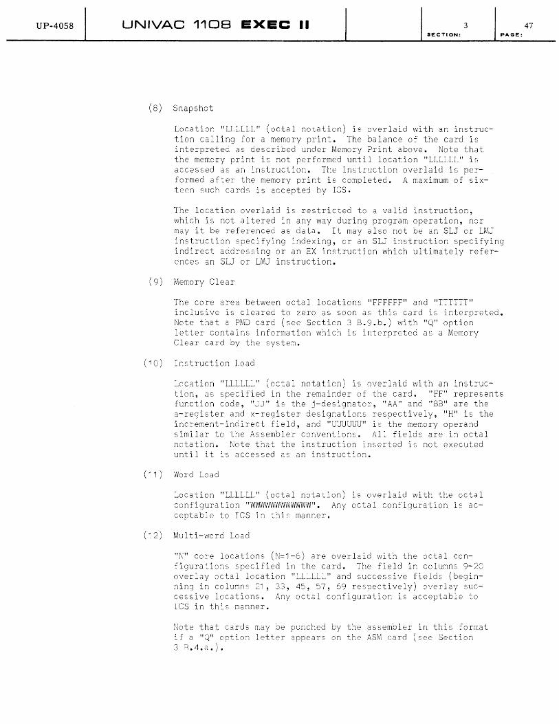
UP-40S8 UNIVAC 1108 EXEC II 3 SECTION:
(8) Snapshot
Location "LLLLLL" (octal notation) is overlaid with an instruction calling for a memory print. The balance of the card is interpreted as described under Memory Print above. Note that the merr.ory print is not performed until location "LLLLLL" is accessed as an instruction. The instruction overlaid is performed after the memory print is completed. A maximum of sixteen such cards is accepted by lCS.
The location overlaid is restricted to a valid instruction, which is not altered in any way during program operation, nor
PAGE:
may it be referenced as data. It may also not be an SLJ or LMJ instruction specifying ~ndexing, or an SLJ instruction specifying indirect addressing or an EX instruction which ultimately references an SLJ or LMJ instruction.
(9) Memory Clear
The core area between octal locations "FFFFFF" and "TTTTTT" inclusive is cleared to zero as soon as this card is interpreted. Note that a PMD card (see Section 3 8.9.b.) with "Q" option letter contains information which is interpreted as a Memory Clear card by the systeM.
(10) Instruction Load
Location "LLLLLL" (octal notaticn) is overlaid with an instruction, as specified in the remainder of the card. "FF" represents fur.ction code, "JJ" is the j-designator, "AA" and "8B" are the a-register and x-register desigr.ations respectively, "H" is the increment-indirect field, and "UUUUUU" is the memory operand similar to the Assembler conventions. All fields are in octal notation. Note that the instruction inserted is not executed until it is accessed as an instruction.
( 11) Word Load
Location "LLLLLL" (octal notation) is overlaid with the octal configuration "WWvVWWWWWWvVWW". Any octal configuration is acceptable to ICS in this manner.
(12) Multi-word Load
"N" core locations (N=1-6) are overlaid with the octal configurations specified in the card. The field in columns 9-20 overlay octal location "LLLLLL" and successive fields (beginning in columns 21, 33, 45, 57, 69 respectively) overlay successive locations. Any octal configuration is acceptable to IeS in this manner.
Note that cards may be punched by the assembler in this format if a "Q" option letter appears on the ASM card (see Section 38.4.a.).
47

UP-4058 UNIVAC 1108 EXEC II 3 SECTION:
NOTE: The cards described in paragraphs 2, 10, 11 and 12 may be used in conjunction with the bootstrap routine to form a simple card loader (console jump switch 15 must be set). Locations 000200 to 000337 (octal) may not be loaded in this manner. In addition, system patches may be entered by the same means (setting console jump switch 13); in this case, the terminating card should be a jump to location 000005. If used in this way, the operations card should not be preceded by a call to ICS. This card load routine is not available if the system has no standard card reader; it may not be used from a 1004 Card Processor.
b. PMD Control Card
The PMD card is a control card used to call the Post-Mortem Dump routines. These routines are special systems programs which print specified areas of core, drum and registers after termination of a worker program. The information printed is available in the Execution Area on drum (see Section 2 B.4.), provided the Allocator was not prevented from constructing the required tables (see Section 3 B.5.c.) by use of the "z" option (see Appendix C 2.). The PMD card is identified by the word "PMD" in the card name field, and contains an options field and a specifications field. Generally, this card has "free-form", i.e., specific card columns do not determine the fields; however, if the "Q" option is specified, the card has a fixed format as follows:
Column 2 Column 3 Column 4 Columns 5-7 Column 8 Columns 9-80
"Q" "E" or blank (programmer's choice) blank "PMD" blank identical to the "Memory Print card" for ICS (see Section 3 B.9.a.)
The fields of the PMD card are described below. (See Appendix C 3. for format.)
(1) Options Field
This is a string of letters from the set (A,B,C,D,E,I,Q,V,X). A maximum of one of the letters (A, D, I) may be used, "X" 'applies only in conjunction with (A, D, I) and "Q" is a special option which is restricted as mentioned in the previous paragraph. (See Appendix C 2 •• )
(2) Specifications Field
This field has three forms depending on the options chosen. If the "Q" option is used, the specifications field is identical to columns 9-80 of the ICS memory clear card, as previously mentioned. If any of the special options (A, D, I) is used, the specifications field contains a sequence of element or segment names (see Section 3 B.5. on "segments", Section 3 B.6. on "elements") separated by commas and terminating with a blank. All dumps applying
48 PAGE:

UP-40S8 UNIVAC 1108 EXEC II SECTION:
to PMD cards with this format will be in octal notation. Otherwise, the specification field contains four subfields, separated by commas, and terminating with a blank; if a field is to be omitted, the comma which follows it should appear on the card so that the interpreting routines will not misinterpret the card. The subfields are as follows:
Name: An element name (if blank all of user core is specified).
Start: "n$m", where m is the location counter number
3
(in decimal notation) and n the first address relative to that location counter (in decimal notation) to be dumped. (If "m" or "n" is omitted, a zero value is assumed; if the entire field is omitted, interpretation of the card ends, and all of the element name is assumed with all dumps produced in octal notation.)
Length: Number of words to be dumped in decimal notation. (If blank, all of the area specified by the previous subfields is implied.)
Format: This may contain a single letter; as follows, or any user-defined format in FORTRAN notation, enclosed in parentheses. A description of FORTRAN Format specifications is included in Section 4 B.2.a ••
A
E
F
I
o or blank
System Response
Alphanumeric (16 A 6)
Floating Decimal (8E 14.8)
Fixed Decimal (8F 14.8)
Integer (81 14)
Oc ta 1 (80 1 4 )
When eel (see Section 2 B.1.) encounters a PMD card, it places it in the output print file and proceeds to call in routines to interpret it. If the conditions required for dumping, as specified by the options used, and the required tables are
.available (except for "Q" option), the dump routines are called in and executed. If the tables are not available, or if through an error the program was not executed, an error message (see Appendix E) is placed in the print file. If for any reason no dumping takes place, the PMD card is ignored with no error indication. After processing the PMD card, eel is re-entered to read another control card.
49 PAGE:
UP-40S8 UNIVAC 1108 EXEC II 3 SECTION:
c. Panic Dumps
Under some circumstances, it may not be possible to complete a job. If such a condition occurs and the job has not yet terminated, it is still possible for the programmer to get useful information for debugging. The information is obtained by a panic dump, which is an octal listing of specified areas of core in absolute terms. This technique should not be used to replace other diagnostic techniques; rather, it is a last resort, to be used only under conditions which prohibit normal use of the system. To specify a panic dump, the programmer must give the beginning and ending locations (in octal notation) of those core areas required.
Panic Dump Procedure
While this procedure is essentially an Operator's job, the programmer should understand it to emphasize the "last resort" aspect of it.
PAGE:
The operator must perform a manual bootstrap of the system with console jump switch 14 set. When the computer halts, the first location to be dumped is manually entered into the P-register. The START button is pressed and when the computer halts again, the last location to be dumped is similarly entered into the P-register. The specified area is then printed. This procedure is repeated for each such area to be dumped, after which the console jump switch is reset, and the system restored by a manual bootstrap.
The format of the dump is six words to the line, in octal notation, with the address of the first word on the far left of the line, also in octal. A pair of asterisks following the address indicates duplication of the information of the previous line, in which case the duplicate line is omitted.
10. Control Card Errors
Any of a number of conditions causes a control card to be considered erroneous by the system. Two of the major causes of control card errors are:
1. Invalid information in the card.
2. Card misplaced in deck or missing.
a. Invalid Information
The first error listed occurs when the formatting rules for the control card have been violated, or when an invalid character has been detected, or when an unrecognizable control card is encountered (such as a COL card in a deck not input from the 1004). Descriptions of the control cards in Sections 3 B.1. through 3 B.9. and Appendix C indicate the proper construction of each control card. When this error occurs, a message is placed in the print file:
"ABOVE CONTROL CARD IN ERROR - IGNORED"
If another control does not immediatly follow the error (and under some other conditions), the job is aborted, i.e., no further processing of any kind is done in the current job. All succeeding cards
50

UP-4058 UNIVAC 110B EXEC II 3 SECTION:
until the next RUN card are bypassed in this case with messages:
"REMAINING CONTROL CARDS IGNORED"
"DATA CARDS ENCOUNTERED BY SYSTEM-IGNORED"
Careful checking of all control cards used will prevent this error. Note that errors in CUR pseudo-instructions cards (see Section 3 B.6.) also cause job abortion.
b. Misplaced Card
The second type of error may occur when the system expects a RUN card (see Section 3 B.1.a.) or ASG card (see Section 3 B.1.b.) which is not encountered. The following messages signal this condition (and cause job abortion):
"RUN CONTROL CARD MISSING-DECK NOT ACCEPTED"
"ASG CARD MISSING"
Misplaced TPR or DPR cards (see Section 3 B.3.b.) also cause the second type of error condition. If any cards are encountered between the RUN card and a TPR or DPR card (other than a possible HDG card; see Section 3 B.3.c.), the TPR or DPR card is ignored with the message "UPCERR" provided. This condition does not cause job abortion.
c. Control Cards
It is generally impossible for a worker program to make use of any control card; the only exception is the EOF card (see Section 3 B.3.a.). Any attempt to do so causes the worker program to be notified of an error condition by an abnormal return from the card read routine, CREAD (see Sections 2 A. and 4 B.1 .a.), with register A¢ set negative. All subsequent calls to CREAD produce the same result.
51 PAGE:

UP-40S8 UNIVAC 110B EXEC II 4 SECTION:
4. \NORKER PROGRAMS
A. SPECIAL SYSTEM PACKAGES
1. SORT, LIFT, APT, PERT, etc.
Certain special programs are available for use under EXEC II. These are described in detail in other documents; it is the purpos~ of this section to clarify that aspect of their usage which involves interfacing with EXEC II.
Programs such as SORT may be called upon by a user job only if they are in the User PCF (see Section 2 B.5.). It must be brought in to the User PCF by the same techniques employed for user-designed programs. This implies that the special program must exist in card, tape, or other form external to the operating system before it may be used.
One exception to this is LIFT; two versions of LIFT are available. The first is a special package (as above) which produces card output. The second is a processor (see Section 4 A.2.) which produces a symbolic element in the User peF as output.
All interfaces between packages such as SORT and EXEC II are identical to the interface between any user-designed program and EXEC II (see Section 4 B.), and the system reacts similarly to both.
2. Processors
The EXEC II system includes a set of special programs available to user jobs. These may be called without first bringing them in, since they are built into the system and reside on drum when not in use. In this aspect they resemble other non-resident system routines. The method of calling each of the processors is described in Sections 3 B.4., 3 B.5., 3 B.6., and 3 B.9. References to other documentation is provided in these sections for processors not fully described in this manual.
Despite the fact that the processors are included in the system, they are restricted in their operation in the same way user-designed programs are. In this, they resemble the special packages mentioned in Section 4 A.1. Once a processor has been loaded and turned on, the system reacts to it as it would to any user-designed program.
1 PAGE:

UP-40S8 UNIVAC 1108 EXEC II 4 SECTION:
B. USER-DESIGNED PROGRAMS
This section outlines the interfaces between user-designed worker programs and various parts of the system. Calling sequences are included for use of the system routines to handle input-output, perform editing, utilize the Real-Time Clock, or provide diagnostic control.
Note t~at the specialized worker programs discussed in Section 4 A. use the same interfaces as are described in this section; however, the user need not concern himself with interface techniques in order to efficiently use the special packages even though he must understand these techniques to design and build his own programs.
All linkages are given in 1108 Assembler mnemonics. An understanding of the Assembler is prerequisite to the proper use of this section. Alternative linkages are given in terms of special Assembler PROC directives designed for ease in coding. These generate the linkage as given in 1108 Assembler mnemonics. All routines not specifically designated as resident routines are contained in the system library. The resident routine entry points are contained in a jump table in VECTOR (see Section 2 A.); the worker program jumps to the location in VECTOR in which a jump to the required routine is stored. Since VECTOR remains constant, no changes are necessary to worker programs when system revisions are made, even if a change is made in the location of any subroutine available to worker programs.
1. Input-Output Specifications
a. Symbionts and Co-operatives
A symbiont is a special program which transfers data between a peripheral device and an intermediate storage device. A co-operative is a special routine which transfers data between a worker program and an intermediate storage medium. A worker program receives its input from an input co-operative which takes data from the intermediate storage area into which an input symbiont placed it, and gives its output to an output cooperative which places data into intermediate storage for action by an output symbiont. The co-operative routines are included as part of the resident (see Section 2 A.) while the symbionts are retained on the drum as independent non-resident programs (see Section 2 B.1.).
(1) Table of Symbionts and Co-operatives
Table 4-1 ~ists the symbionts with their respective co-operatives, their function and the stimuli which turn them on and off. Also included in the table are special routines which operate like symbionts but do not transfer data; these are marked with an asterisk. Following this table is a description of calling sequences for the cooperatives. (paragraph 3-8). Note that symbionts are not called directly by worker programs. An outline of symbiont operation is included in paragraphs 9-16, and some remarks about particular symbionts are in paragraph 17.
2 PAGE:

UP-4058 UNIVAC 1108 EXEC II 4 3 SECTION: PAGE:
Table 4-1 Symbionts and EXEC Control Routines Which Operate Like Symbionts
Symbiont Initiated Terminated Cooperati ve Initiated Termina ted Name By By Function of Symbiont Name By By Function of Cooperative Reference
CP 1 THP or end-file Transfer images from tape CPNCH Worker Pro- Transfer punch files from CPNCH or drum to an on-site card gram or core to tape or drum.
punch. system
CP7 THP or end-file Trans fer images from tape or CPNCH Worker Pro- Transfer punch fi les from CPNCH drum to a remote card punch. gram or core to tape or drum.
system
CRI GNP end-fil e and Transfer card images from CREAD Worker Pro- end job "FIN" card on-si te standard card reader gram, system, Section
to drum. CRI 4 B.1.a.
CR4 GNP 2 "FIN" cards Transfer card images from CREAD Worker Pro- Transfer card files from on-site 1004 card processor gram, system, main storage to core. to drum. CR4
CR7 Remote 1004 Remote stop Transfer card images from CREAD Worker Pro-operator card remote 1004 card processor gram, system,
to drum. CR7
DLT PRINT end-file Transfer print files from PRINT user job Transfer print images drum to tape after convert- from main storage to ing to DLT-5 format. tape or drum.
DMP THP end of data Transfer specified symbiont files from drum to tape.
GNP Consol e sel f termi- Analyze keyin and load 1108 operator nating routine to provide requested Operators keyin action Reference
Manual LOD THP end of data Transfer specified symbiont
files from tape to drum.
PRT THP or end-file Transfer print images from PRINT drum or tape to standard
printer
PRT THP or end-file Transfer print images from PRINT user job end job Transfer priClt images Section PRINT drum or tape to on-site from main st:)rage t:) 4 B.1.a.
1004 prir.ter tape or drum.
PR7 THP or end-file Transfer print images from PRINT drum or tape to remote
1004 prir.ter.
QPl THP end-file Transfer images from tape Section to paper tape punch (not 4 B.l.e. 1004).
QRl THP paper tape Transfer images from paper stop code tape punch to magneti c tape
(r.ot 1004).
TAP GNP self termi- Assign magnetic tape uni t nating according to console keyin. 1108
Operators THP* GNP self termi- Perform speci fied magnetic Reference
nating tape operations according Manual to console keyin.
* Specifies Control Routine.
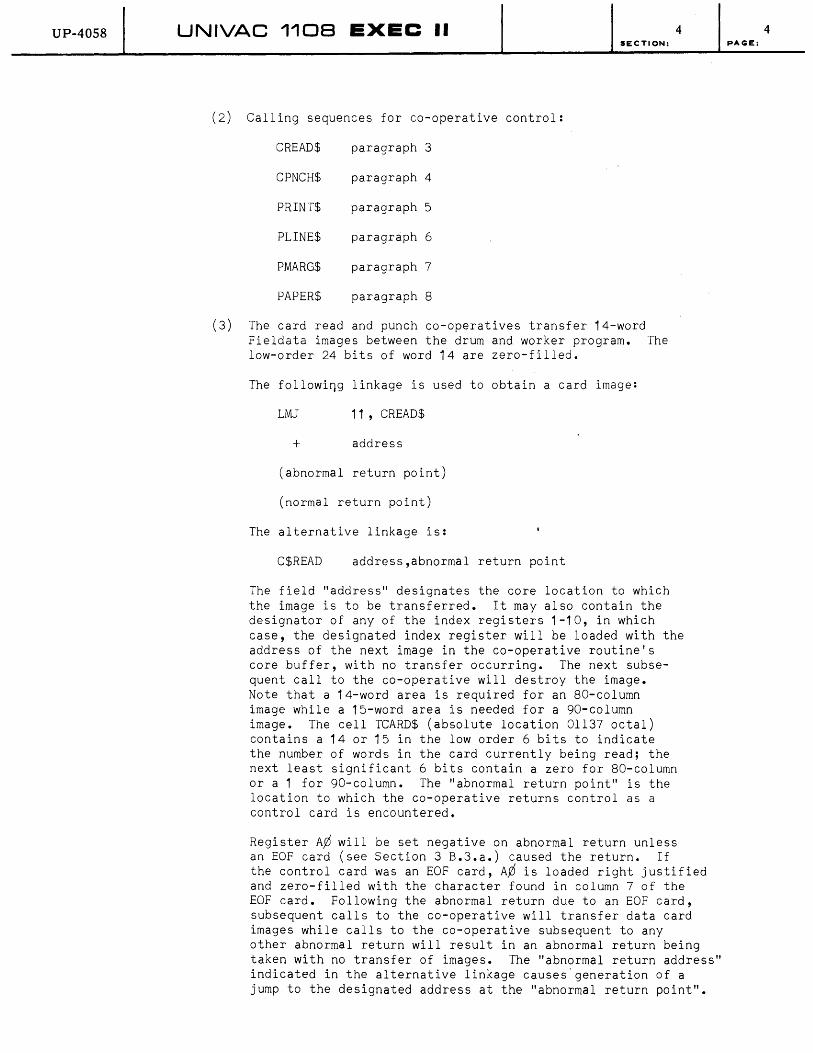
UP-4058 UNIVAC 1108 EXEC II 4
(2)
(3)
SECTION:
Calling sequences for co-operative control:
CREAD$ paragraph 3
CPNCH$ paragraph 4
PRINT$ paragraph 5
PLINE$ paragraph 6
PMARG$ paragraph 7
PAPER$ paragraph 8
The card read and punch co-operatives transfer 14-word Fieldata images between the drum and worker program. The low-order 24 bits of word 14 are zero-filled.
The followi~g linkage is used to obtain a card image:
LMJ 11 , CREAD$
+ address
(abnormal return point)
(normal return point)
The alternative linkage is:
C$READ address,abnormal return point
The field "address" designates the core location to which the image is to be transferred. It may also contain the designator of any of the index registers 1-10, in which case, the designated index register will be loaded with the address of the next image in the co-operative routine's core buffer, with no transfer occurring. The next subsequent call to the co-operative will destroy the image. Note that a 14-word area is required for an 80-column image while a 15-word area is needed for a 90-column image. The cell TCARD$ (absolute location 01137 octal) contains a 14 or 15 in the low order 6 bits to indicate the number of words in the card currently being read; the next least significant 6 bits contain a zero for 80-column or a 1 for 90-column. The "abnormal return point" is the location to which the co-operative returns control as a control card is encountered.
Register A~ will be set negative on abnormal return unless an EOF card (see Section 3 B.3.a.) caused the return. If the control card was an EOF card, AP is loaded right justified and zero-filled with the character found in column 7 of the EOF card. Following the abnormal return due to an EOF card, subsequent calls to the co-operative will transfer data card images while calls to the co-operative subsequent to any other abnormal return will result in an abnormal return being taken with no transfer of images. The "abnormal return address" indicated in the alternative linkage causes'generation of a jump to the designated address at the "abnormal return point".
4 PAGE:

UP-4058 UNIVAC 1108 EXEC II 4 SECTION:
If this field is omitted, the line following the PROC call is taken as the "abnormal return point".
(4) The following linkage is used to transfer a card image to the punch co-operative:
LMJ 11 , CPNCH$
+ n,address
The alternative linkage is:
C$PNCH address,n
The field "address" designates the core location from which the image is to be transferred. The field "n" is a number between 0 and 14 specifying the number of words in the i mag e • If" n " i s 0 mit ted, a val u e. 0 f 1 4 i s ass um e d • I f "n" is given as less than 14, the co-operative transfers "n" words into the top of a 14-word blank-filled image area, thus filling the image with trailing blanks. The transfer will be completed, in any event, before return from the co-operative. (If the punch file is to be output on a 90-column device, the maximum value for "n" is 15; this replaces the 14 throughout the preceding paragraph. If a system has both an 80- and 90-colum~ punch, one of them must be designated as "special", and may be accessed only by channel selection on the RUN card; see Section 3 B.1.a.).
(5) The print co-operative transfers 22-word Fieldata images between drum and worker program.
The following linkage is used to transfer a print image:
LMJ 11 ,PRINT$
P s,n,address
(In which: P FORM 12,6,18)
The alternative linkage is:
P$RINT address,n,s
The field "address" designates the core location from which an image "n" words long (0~n~22) is to be transferred. The field "s" is used to generate a control to skip "s" lines prior to printing. If "n" is zero, a blank line is printed; if "s" is zero, overprinting occurs. If "s" is omitted from the procedure call, it is assumed to be 1; if "s" is greater than the number of logical lines per page (see paragraph 7), a control to eject the current page is set; if "n" is omitted it is assumed to be 22. If "n" is less than 22, a stop code (77) is generated following the last word of the image; print images may thus be variable in length.
5 PAGE:
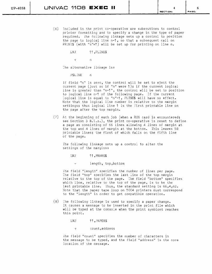
UP-4058 UNIVAC 1108 EXEC II 4 SECTION:
(6) Included in the print co-operative are subroutines to control printer formatting and to specify a change in the type of paper required. The following linkage sets up a control to position the page to logical line n-1, so that a subsequent calIon PRINT$ (with "s"=1) will be set up for printing on line n.
LMJ 11 ,PLINE$
+ n
The alternative linkage is:
P$LINE n
If field "n" is zero, the control will be set to eject the current page (just as i,f "n" were 1); if the current logical line is greater than "n-1", the control will be set to position to logical line n-1 of the following page. If the current logical line is equal to "n"-1, PLINE$ will have no effect. Note that the logical line number is relative to the margin settings; thus logical line 1 is the first printable line on the page after the top margin.
(7) At the beginning of each job (when a RUN card is encountered; see Section 3 B.1.a.), the print co-operative is reset to define a page as consisting of 66 lines allowing 4 lines of margin at the top and 4 lines of margin at the bottom. This leaves 58 printable lines; the first of which falls on the fifth line of the page.
The following linkage sets up a control to alter the settings of the margins:
LMJ 11 ,PMARG$
+ length, top,bottom
The field "length" specifies the number of lines per page. The field "top" specifies the last line of the top margin relative to the top of the page. The field "bottom" specifies which line, relative to the top of the page, is to be the last printable line. Thus, the standard setting is 66,4,62. Note that the paper tape loop on 1004 printers must correspond to the "length" in order to get compatible operation.
(8) The following linkage is used to specify a paper change. It causes a message to be inserted in the print file which will be typed at the console when the print symbiont reaches this point.
LMJ 11 , PAPER$
+ count,address
The field "count" specifies the number of characters in the message to be typed, and the field "address" is the core location of the message.
6 PAGE:
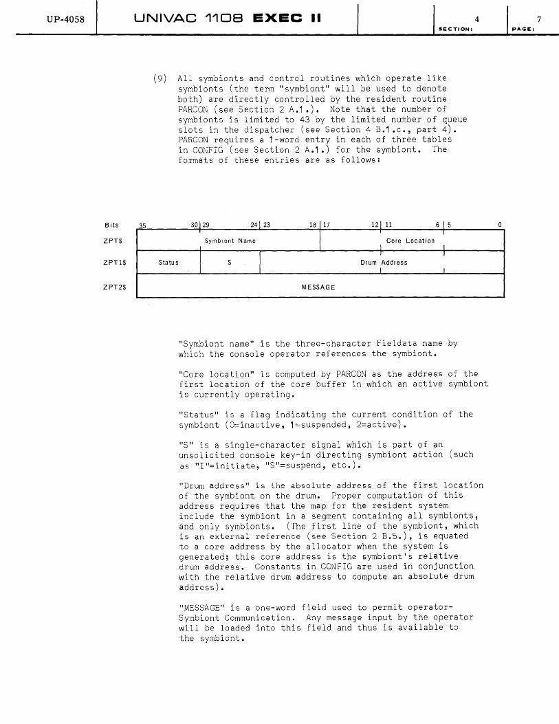
UP-40S8
Bits
ZPT$
ZPT1$
ZPT2$
UNIVAC 1108 EXEC II 4
35
SECTION:
(9) All symbionts and control routines which operate like symbionts (the term "symbiont" will be used to denote both) are directly controlled by the resident routine PARCON (see Section 2 A.1 .). Note that the number of symbionts is limited to 43 by the limited number of queue slots in the dispatcher (see Section 4 B.1 .c., part 4). PARCON requires a 1-word entry in each of three tables
Statu s
in CONFIG (see Section 2 A.1.) for the symbiont. The formats of these entries are as follows:
30129 24123 18 17 121 11 6 I 5 , , I Symb iont Name Core Location
I I
I I I
S Drum Address I I
MESSAGE
"Symbiont name" is the three-character Fieldata name by which the console operator references the symbiont.
"Core location" is computed by PARCON as the address of the first location of the core buffer in which an active symbiont is currently operating.
"Status" is a flag indicating the current condition of the symbiont (O=inactive, 1=suspended, 2=active).
"S" is a single-character signal which is part of an unsolicited console key-in directing symbiont action (such as "I"=initiate, "S"=suspend, etc.).
"Drum address" is the absolute address of the first location of the symbiont on the drum. Proper computation of this address requires that the map for the resident system include the symbiont in a segment containing all symbionts, and only symbionts. (The first line of the symbiont, which is an external reference (see Section 2 B.5.), is equated to a core address by the allocator when the system is generated; this core address is the symbiont's relative drum address. Constants in CONFIG are used in conjunction with the relative drum address to compute an absolute drum address).
"MESSAGE" is a one-word field used to permit operatorSymbiont Communication. Any message input by the operator will be loaded into this field and thus is available to the symbiont.
7 PAGE:
0

UP-4058 UNIVAC 1108 EXEC II SECTION:
The system sets a cell called ZSW$ to the index of the ZPT$ entry (relative to the beginning of the ZPT$ table) whenever a symbiont is given control. Register X1 will concurrently be set by the system to the address "core location" in the ZPT$ entry.
4
Whenever an unsolicited key-in involving symbiont action occurs (normally identified by a "." as first character), the control routine GNP is called in; this routine interprets the signal character (field "s" in ZPT$ table) and enters the subroutine in PARCON which will perform the desired operation. The symbiont itself (or other resident routines) may also enter subroutines in PARCON to perform specified operations. The subroutines of PARCON are described in the following paragraphs (Note that these subroutines are not defined by the system for worker programs):
ZINS paragraph 10 ZFILE$ paragraph 13
ZIN,SP paragraph 10 ZNEXT$ paragraph 13
ZREM paragraph 11 ZSUB1 paragraph 14
ZRCB$ paragraph 12 ZSUB2 paragraph 14
ZLCB$ paragraph 12 ZLOAD paragraph 14
ZRDB$ paragraph 12 ZSPND$ paragraph 15
ZLDB$ paragraph 12 ZTERM$ paragraph 16
Since the symbionts interact closely with the system, no provision is made for saving and restoring registers when it releases and regains control. The only registers available for free use by symbionts are the "volatile" registers B11 through A5 and R1 through R3. All other registers used by a symbiont must be saved and restored by the symbiont between transfers of control.
(10) The subroutine ZINS is used to place an entry in one of the queues maintained by the dispatcher (see Section 4 B.1 .c.). It requires that A¢ contain the index of the symbiont's entry in the ZPT$ table (relative to the beginning of the table); and that A1 contain the index of the point in the symbiont (relative to the first location of the core buffer in which the symbiont is operating) to which control is to be returned after the action specified in the queue entry is completed; and that A2 contain the address of the location which identifies the queue. The calling sequence is:
LMJ 11 ,ZINS
If a symbiont, which is currently active needs to place an entry into a queue, the subroutine ZINSP should be used. This requires that A2 contain the address of the location which identifies the queue (as above); and that ZSW$ contain the index of the symbiont's entry in the ZPT$
8 PAGE:

UP-40S8 UNIVAC 1108 EXEC II SECTION:
table (relative to the beginning of the table); and that X11 contain the absolute address of the point in the symbiont to which control is to be returned after the action
4
is specified in the queue entry is completed. When this subroutine is entered, A¢ is loaded from lSW$, A1 is loaded with the difference between X11 and X1, and X11 is loaded with the address of SIRT in INTRP (see Section 2 A.). The subroutine then enters ZINS.
The calling sequence to this subroutine is:
J ZINSP or LMJ 11 ,lINSP
The action performed by ZINS is to place an entry into the proper queue and exit to the location specified in X11.
(11) ZREM is the subroutine used to remove an entry from one of the queues maintained by the dispatcher (see Section 4 B.1 • c.). A2 must be set as for ZINS, described in paragraph 10. The calling sequence for this subroutine is:
LMJ 11,ZREM
The subroutine removes the first entry from the queue, updates the queue to reflect the availability of the slot it has just released, and then exits to the location specified by B11 •
(12) Five subroutines are provided to control the use of core and drum buffers (see Section 2 A. and 2 B.6.). To request a buffer, the following subroutine linkages are used:
LMJ 11,ZRCB$ (core buffer)
LMJ 11,ZRDB$ (drum buffer)
LMJ 11 ,ZRDBI$ (input drum buffer)
These linkages enter subroutines which load the address of the next available buffer into A¢. If no buffer is available, A¢ is loaded with a zero. If the request was made by a worker program, the subroutine returns control to the worker program (via the address in B11) whether or not a buffer was actually found. If the request was made by a symbiont, the subroutine will not return control to the symbiont unless a buffer is available; if no buffer is available for a symbiont, the subroutine ZINSP (see paragraph 10) is entered to place the request in the proper queue (Note that ZINSP does not return control to the symbiont).
To release a buffer, the following linkages are used:
LMJ 11 ,ZLCB$ (core buffer)
LMJ 11,ZLBD$ (drum buffer)
9 PAGE:
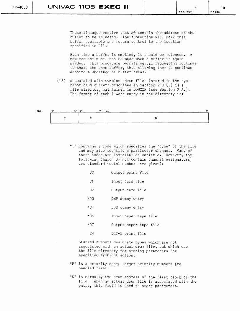
UP-4058
Bits
UNIVAC 1108 EXEC II 4 SECT10N:
These linkages require that A¢ contain the address of the buffer to be released. The subroutine will mark that buffer available and return control to the location specified in B11.
Each time a buffer is emptied, it should be released. A new request must then be made when a buffer is again needed. This procedure permits serval requesting routines to share the same buffer, thus allowing them to continue despite a shortage of buffer areas.
(13) Associated with symbiont drum files (stored in the symbiont drum buffers described in Section 2 B.6.) is a file directory maintained in LOWCOR (see Section 2 A.). The format of each 1-word entry in the directory is:
T
25 24
p o
"T" contains a code which specifies the "type" of the file and may also identify a particular channel. Many of these codes are installation variable. However, the following (which do not contain channel designators) are standard (octal numbers are given):
00 Output print file
01 Input card file
02 Output card file
*03 DMP dummy entry
*04 LOD dummy entry
*06 Input paper tape file
*07 Output paper tape file
24 DLT-5 print file
Starred numbers designate types which are not associated with an actual drum file, but which use the file directory for storing parameters for specified symbiont action.
"P" is a priority code; larger priority numbers are handled first.
"D" is normally the drum address of the first block of the file. When no actual drum file is associated with the entry, this field is used to store parameters.
10 PAGE:
o

UP-40S8 UNIVAC 1108 EXEC II SECTION:
Two subroutines in PARCON are used to maintain the file directory. To add an entry in the directory, A¢ should be loaded with the word to be added and the following linkage executed:
LMJ 11 ,ZFILE$
4
If the file directory is full when the above linkage is executed, no entry is made, and A¢ is set negative. If the entry is successfully made, A¢ is set positive. Control is always returned to the location specified in X11.
To remove an entry from the directory, A¢ should be loaded with the type code desired (right justified), and the following linkage executed:
LMJ 11, ZNEXT$
The subroutine ZNEXT$ will search the directory for the highest priority entry for the indicated type code (in A¢). If found, the entry word is loaded into A¢ and the entry is deleted from the directory. If no entry of the indicated type is found, A¢ is set negative. Control is always returned to the location specified in B11.
(14) Three subroutines are provided in PARCON for use in initiating a symbiont. The first is used to get the index of the symbiont entry in the ZPT$ table. This subroutine requires that the name of the symbiont be loaded into A¢ (right justified) and the following linkage executed:
LMJ 11, ZSUB1
If the symbiont is found, control is returned to the location specified in X11 with A1 set to the required index. If the symbiont is not found, the operator is notified by a console typeout and control is returned to SIRT in INTRP (see Section 2 A.).
The second subroutine provided is used to check the symbiont loader for activity, and activate it if it is inactive. This subroutine requires that A1 be set to the index of the symbiont entry in ZPT$ table and the following linkage executed:
LMJ 11 ,ZSUB2
If the loader is already active, control is returned to the location following the address in B11. Otherwise the loader and the symbiont to be loaded are both marked active in ZPT$ table, and the index to the symbiont entry in ZPT$ is loaded into the "symbiont name" field in the loader's entry in ZPT$. Entry is then made to ZINS (with A¢, A1 and A2 properly reset) to place an entry for the loader into the "ready" queue. X11 is not reset when ZINS is entered. The symbiont loader is thus made to look like a symbiont to the system.
11 PAGE:

UP-4058 UNIVAC 1108 EXEC II 4 SECTION:
When the entry in the "Ready" queue for the loader gets to the top of the queue, the subroutine ZLOAD is entered; this is the symbiont loader. Using the dummy entry in the ZPT$ table (into which was stored the index to the ZPT$ entry for the symbiont to be loaded), ZLOAD requests a core buffer (using ZRCB$) and loads the requested symbiont into it. ZSW$ is then set to the symbiont's index in the ZPT$ table, and X1 is set to the address of the first location in the core buffer. ZLOAD is inactivated at this point and the dispatcher (see Section 4 B.1 .c.) is entered to release the drum channel and place the symbiont into the "Ready" queue. Upon completion of its operation, the dispatcher exits to SIRT in INTRP (see Section 2 A.). The symbiont called for is effectively active at this point.
(15) A symbiont may temporarily suspend operations by means of the linkage:
LMJ 11,ZSPND$
When this subroutine is entered, the ZPT$ table entry for the currently active symbiont is marked with a 1 in the "status" field to mark it suspended. The difference . between the addresses in X11 and X1 is loaded into the first location in the symbiont's core buffer. (Note that the symbiont must therefore provide a constant in its first word which should be assembled as the relative start point, and which is updated by such routines as ZSPND$). This permits re-entry to the symbiont when the operator next addresses it by an unsolicited Key-in. ZSPND 'returns control to SIRT in INTRP (see Section 2 A.) after completing its operations.
(16) A symbiont may terminate operations by means of the linkage:
LMJ 11,ZTERM$
This subroutine notifies the operator of symbiont termination and then releases its core buffer by using the subroutine ZLCB$. (A~ is first loaded with the address in X1 , which contains the address of the first location in the core buffer of the currently active symbiont). The ZPT$ table entry for the symbiont is then marked inactive ("status"=O), and ZTERM$ returns control to SIRT in INTRP (see Section 2 A.).
(17) It should be noted that certain symbionts are "channeldependent", i.e., they are associated with particular channels co~taining specific hardware devices. This is true of the print, card read, card punch and paper,tape symbionts. Some clarifying remarks regarding these symbionts are included here.
There ar~ three card read symbionts: CR1, CR4, and CR7. These are associated with channels containing a standard card-reader, an on-line 1004 card processor, and aCTS unit which links to a remote 1004 card processor, respectively. If an installation has more than one
12 PAGE:

UP-4058 UNIVAC 1108 EXEC II SECTION:
channel containing any of this equipment, an additional entry for the second channel's symbiont is created for
4
the ZPT$ table which references the ~ symbiont as the first channel with a different name. Thus, entries may be found in ZPT$ table for symbionts called CR1, CR2, CR3, all of which refer to the symbiont CR1. The symbiont CR4 may also be referenced by entries with names CR5, CR6, similarly CR7 may be renamed CR8, CR9.
The same discussion holds true for the print symbionts, PRT (usually named PR1 on the first printer channel), PR4, and PR7. The card punch symbiont CP1 contains coding for use with a 1004 card processor, and thus may be renamed CP4, CPS, CP6 as well as CP2, CP3. CP7 may be renamed CP8, CP9. The paper tape symbionts exist only in the form associated with standard paper tape units (not 1004 processors equipped with paper tape read or punch units). However, more than one standard paper tape read or paper tape punch channel is possible; the symbionts QR1 and QP1 are correspondingly renamed QR2, QR3, and QP2, QP3.
The symbiont DLT exists in only one form, since it is associated with a magnetic tape unit which is dynamically assigned; similarly for the symbionts DMP and LOD.
The symbionts DMP and LOD and the control routines GNP, TAP and THP provide the console operator with the useful capabilities described in the 1108 EXEC II Operator's Reference Manual. These symbionts are therefore not discussed in detail in the present manual.
b. Tape and Drum Routines
This section includes a description of all system routines providing interface with magnetic tape units and the FH-880 or FH-432 drum. The section is divided into six parts. Parts 1 and 2 deal with tape subroutines: tape assignment being discussed in part 1 and the resident tape I/O package in part 2. Parts 3 and 4 deal with the resident subroutines: normal mode routines in part 3 and packet mode routines in part 4. The last two parts in this section deal with the buffering routines for drum and tape included in the standard library; the Block Buffering package is discussed in part 5, and the Label and Item package in part 6. Note that the former is used for tape or drum blocks of any format, while the latter deals with LION format tapes.
A discussion of end-action subroutines (including the standard verification routines) and access words is provided in Section 4 B.1 .c. This discussion should be used to clarify those portions of the current section which mention requirements for end-action or access words.
13 PAGE:
UP-40S8 UNIVAC 1108 EXEC II SECTION:
(1) Tape Assignment Subroutines:
(a) Six routines are provided in the standard library dealing with magnetic tape assignments. Four of them (marked '*', below) may not be used in endaction routines. The tape subroutines are:
*TASGN$ paragraph b TLABL$ paragraph c
THRU$ paragraph b *TSCRH$ paragraph b
*TINTL$ paragraph d *TSWAP$ paragraph d
All of the above routines require that a "logical" tape label be specified (this is the same as the "logical" label on the ASG control card described in Section 3 B.1.b.). The "logical" label of the
4
tape unit is a single character (A-Z,-, or right parenthesis) used to refer to the unit within a worker program. The system provides the capability for equating the logical label to an "operational" label, the name by which the tape is known to the operator. Normally, the operator is responsible for providing a physical unit assignment corresponding to an "operational" label, while the programmer provides the correlation between the "operational" label and his "logical" label. This is the case when the above subroutines are used. These subroutines, however, do not notify the operator of the requirement for a physical unit assignment. (When an ASG card is used, the programmer may optionally specify physical unit assignments; if he does not, the system notifies the operator to make the assignment and waits until he does so).
(b) Tapes may be assigned by two of the subroutines, and released by one. To assign a "logical" label to an "operational" label, the "operational" label should be loaded into A¢ (right justified and zerofilled) and the following linkage executed:
LM] 11 ,TASGN$
+ 0, ' logical'
(abnormal-return-point)
(normal-return-point)
The "logical" field should contain a "logical" label, enclosed in quotation marks. If the "logical" label is invalid, or if the "operational" label has not been equated to a physical unit by the operator, control is returned to the "abnormal-return-point". If the assignment is made, control is returned to the "normal-return-point".
14 PAGE:
UP-4058 UNIVAC 110B EXEC II SECTION:
Similarly, a scratch tape (operational label= ,*,) may be assigned by the following linkage (A~ is not used):
LMJ 11 ,TSCRH$
+ 0, 'logical'
(abnormal-return-point)
(normal-return-point)
4
The fields correspond to the TASGN$ linkage, except that an abnormal return is made when no scratch tapes are available. Note that the difference between a scratch tape and a labeled tape is that the system prohibits reassignment of an "operational" label while it is in use, except for "*"; thus any number of scratch tapes may be assigned.
The above linKages may be made by the following procedure calls:
T$ASGN 'logical' ,(abnorm)
T$SCRH , logical' ,( abnorm)
These procedures should contain the address of the abnormal-return-routine in the "(abnorm)" field. The system loads the abnormal-return-point in the linkage with
J (abnorm)
if this address is provided, or with
NOP
otherwise.
To release a "logical" label, thus clearing the physical and "operational" assignments associated with it, the following linkage is used:
LMJ 11 ,THRU$
+ r,'logical'
The 'logical' field should contain a "logical" label. The "r" field designates rewind options as follows:
r=O Rewind all units.
r=1 Do not rewind units.
r=3 Rewind all units with interlock.
All physical units associated with the given "logical" label will be released, with the rewind control applying to each such unit. The operator will be notified that the physical units are now free.
15 PAGE:
UP-40S8 UNIVAC 1108 EXEC II 4 SECTION:
Since this linkage is executed between jobs (with r=O) for all "logical" assignments remaining from the previous job, this linkage need not be used unless a tape unit can be released well prior to job termination.
The above linkage may be generated by the procedure call:
T$HRU 'logical' , 'signal'
The 'signal' field is used to generate a value for "r", and should contain one of the following, surrounded by quotation marks:
RWND sets "r"=O
NORWND sets "r"=1
INTLK sets "r"=2
If 'signal' is omitted "r"=O is assumed.
(c) The worker program may recover the "operational" label associated with a given "logical" label by the linkage:
LMJ 11,TLABL$
+ O,'logical'
The "logical" field should contain a "logical" label surrounded by quotation marks. The subroutine loads Ayj with the "operational" label (right justified and zero-filled); if no "operational" label is associated with the given "logical" label, Ayj is cleared to zero. Control is returned to the worker program following the linkage.
(d) Any number of physical units may be assigned to a given "logical" label. These physical units may be cyclically referenced by use of the following linkage:
LMJ 11 ,TSWAP$
+ r,'logical'
The 'log i ca l' field should conta'in a "log ical" 1 abe I; the "r" field is the same as the "r" field of the THRU$ linkage (see paragraph b), except that it applies to the old physical unit only. The subroutine loads A¢ with the next real number and activates the next physical unit associated with the "logical" label ~rior.to returning control to the worker program (following the linkage). The above linkage may be generated 'by th~ following procedure call:
T$SWAP 'lo.9ical' , 'signal'
16 PAGE:

UP-4058 UNIVAC 1108 EXEC II 4 SECTION:
The 'signal' field is identical to the 'signal' field for THRU$ (see paragraph b).
If the same multireel file is to be used more than once in a worker program, the tape-swap cycle must be re-initialized with the following linkage:
LMJ 11 ,TINTl$
+ 'logical'
The "logical" field should contain the same "logical" label used in the TSWAP$ linkage. The above linkage may be generated by the following procedure call:
TSINTL 'logical'
Rewind control is not available in the TINTL$ subroutine.
(2) Tape r/o Package
The tape I/O package facilities for performing the following operations on a UNISERVO tape unit.
a. Rewind b. Rewind interlock c. Read (forward, backward) d. Write e. Write file mark f. Set mode g. Search read (forward, backward, masked) h. Position (forward, backward) i. Position to end-of-file j. Position to start-of-file k. Contingency Write
The particular UNISERYO* tape unit to be used for a tape operation is specified by its logical unit designation. These logical unit designations are represented by the Fieldata code representation of a letter of the alphabet; for example, a reference to logical unit F is specified by coding 'F' in the proper half-word of the calling sequence. Reference to an unassigned unit will produce a message and error termination.
The tape I/O package can maintain simultaneously one operation for each logical unit being used by the program. Operations for units on the same channel will be performed in the order requested. A request for a tape unit already in action will result in a delay in the package until that unit is free. When the return is made from the tape I/O package, all of the parameters in the linkage have been accepted by the package and thus may be altered as desired.
*Trademark Sperry Rand Corporation.
17 PAGE:

UP-40S8 UNIVAC 1108 EXEC II SECTION:
The 1108 EXEC II tape I/O package functions with UNISERVO IlIA, UNISERVO IVC, UNISERVO VIC, or UNISERVO VIIIC tape units. Not all of the remarks on the following pages apply to all types of units. Those remarks applying to only one unit or the other will be identified with the notation "IlIA", "IVC", or "VIIIC".
(a) Status Codes.
Associated with each operation being performed by a tape unit is a status code. It has the values -
o Normal completion
In process
2 Abnormal completion
3 Unrecoverable error
4
Some types of error interrupts will cause the package to reposition the tape and try to reperform the operation. Several attempts will be made, as appropriate for the type of operation and the particular error condition. Should repeated recovery efforts fail, the operator is notified. He may elect to accept the operation "as is", to initiate another set of recovery cycles, or to declare a fault condition. In the latter case the operation is terminated with a status of 3.
For read operations the unacceptable information will be left in core and the tape will be positioned beyond the unreadable block (after the block for forward tape motion, before the block for backward tape motion). This positioning may not be reliable for certain types of tape read failure.
Some types of error interrupts are not considered recoverable. These also produce a typewriter message but will return a status of 3 without operator action.
An abnormal completion is given in the following conditions:
Physical end of tape or beginning of tape, depending on the direction of motion.
A file mark encountered.
The user may query the status of the most recent operation on a particular unit by means of the linkage
LMJ 11 , TCHK$
+error, unit
+abnormal, in process
18 pAGE:
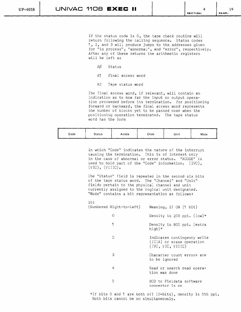
UP-4058 UNIVAC 1108 EXEC II 4
Code
SECTION:
If the status code is 0, the tape check routine will return following the calling sequence. Status codes 1, 2, and 3 will produce jumps to the addresses given for "in process", "abnormal", and "error", respectively. After any of these returns the arithmetic registers will be left as
A¢ Status
A1 Final access word
A2 Tape status word
The final access word, if relevant, will contain an indication as to how far the input or output operation proceeded before its termination. For positioning forward or backward, the final access word represents the number of blocks yet to be passed over when the positioning operation terminated. The tape status word has the form
Status Acode Chan Un it Mode
in which "Code" indicates the nature of the interrupt causing the termination. This is of interest only in the case of abnormal or error status. "ACODE" is used to hold part of the "Code" information. (IVC), (VIC), (VIIIC).
The "Status" field is repeated in the second six bits of the tape status word. The "Channel" and "Unit" fields pertain to the physical channel and unit currently assigned to the logical unit designated. "Mode" contains a bit representation as follows:
Bit (Numbered Right-to-Left)
o
2
3
4
5
Meaning, if ON (1 bit)
Density is 200 ppi. (low)*
Density is 800 ppi. (extra high)*
Indicates contingency write (IlIA) or erase operation (IVC, VIC, VIIIC)
Character count errors are to be ignored
Read or search read operation was done
BCD to Fieldata software convertor is on
*If bits ° and 1 are both off (O-bits), density is 556 ppi. Both bits cannot be on simultaneously.
19 PAGE:

UP-4058 UNIVAC 1108 EXEC II 4 SECTION:
All of the indicators just listed apply to all tape units except where otherwise specified.
The tape status check linkage may be generated by the procedure call
T$CHK unit abnormal, error, in process
If the "in process" parameter is omitted, the generated linkage will loop through the subroutine until the operation is completed. If the "error" parameter is omitted, MERR$ will be substituted.
(b) The Tape Operations
The tape operations listed above are performed by subroutines within the tape I/O package. The linkages have the general form
LM] 11, Txxx$
+end-action, unit
+access word
+sentinel
+mask
The "end-action" field specifies the location of the user's end-action subroutine or may be zero if none is desired. The tape operation will occur on the UNISERVO having the logical designation "unit". For read, write, and search the "sentinel" word is required only for search read operations; the "mask" word is required only for masked search operations for the UNISERVO IlIA's. For position operations, the access word is replaced by the number of blocks to be passed over.
These linkages may also be made by calls to library procedures in the form
T$xxx unit, end-action count, core-addrs, direction sentinel, mask
The first of these three lists contains the logical unit designation in quotation marks and the location of the end-action subroutine. If the "end-action" parameter is omitted, no end-action will occur. The second list specifies the access word using the notation described in Section 4 B.1 .c .. For position forward or backward operations, the second list is the number of blocks to be passed over. The third list, the "sentinel", is present for search read operations only. These procedures will generate two, three, or four words.
20 PAGE:
UP-4058 UNIVAC 1108 EXEC II SECTION:
1. Rewind
A tape unit is rewound by the linkage
LM] 11 , TRW$
+end-action, unit
The operation is marked as complete and the end-action executed if no error interrupt is received within a few milliseconds after the rewind has begun. No abnormal status will be produced.
The rewind linkage may be generated by the procedure call
T$RW unit, end-action
2. Rewind-Interlock
A tape unit is rewound and interlocked against further operations (until reset by the operator) by the linkage
LM] 11 , TRI$
+end-action, unit
The operation is marked ai completed and the end-action executed if no error interrupt is received within a few milliseconds after the rewind has begun. No abnormal status will be produced.
The rewind interlock linkage may be generated by the procedure call
T$RI unit, end-action
3. Read
A block may be read into core, moving the tape in a forward direction, by the linkage
LM] 11 ,TRF$
+end-action, unit
+access word
The operation is completed normally (status=O) by satisfying the access word or by reaching the end of the block or tape. If the former occurs, the tape will move on to the end of the block. An abnormal completion (status=2) may be produced by attempting to read past the end-of-file mark.
4 21 PAGE:
UP-4058 UNIVAC 1108 EXEC II SECTION:
The read forward linkage may be generated by the procedure call
T$RF unit, end-action count, core addrs, direction
A block may be read into core, moving the tape in a backward direction, by the linkage (VIC), (VIIIC):
LMJ 11, TRB$
+end-action, unit
+access word
The operation is completed normally by satisfying the access word or by the beginning of the block or tape. former occurs, the tape will move on beginning of the block. An abnormal (status=2) is produced by attempting past the beginning of tape.
The procedure call
T$RB unit, end-action count, core addrs, direction
(status=O) reaching If the to the completion to read
will generate the read backward linkage.
4. Write
An area of core may be written to tape as a single block by the linkage
LMJ 11 , TWR$
+end-action, unit
+access word
The operation is terminated by satisfying the access word (status=2) or by an unrecoverable error (status=3).
The write linkage may be generated by the procedure call
T$WR unit, end-action count, core addrs, direction
4 22 PAGE:

UP-4058 UNIVAC 1108 EXEC II SECTION:
5. Write File Mark
An end-of-file mark is written on tape with the linkage (IVC), (VIC), (VIIIC):
LMJ 11 , TEF$
+end-action, unit
The write file mark linkage may be generated by the procedure call
T$EF unit, end action
6. Set Mode
4
These linkages determine even or odd parity and high, low, or extra high (lVC, VIC, VIIC) density. They may also be used to turn the BCD-Fieldata hardware convertor on or off (IVC, VIC, VIIIC), set 7 or 9 track mode (VIC, VIIlC) and condition to accept or reject frame count errors. If none of these linkages is used, odd parity and high density are an assumed standard. The setting specified by one of these linkages will remain in effect unti~ an ASG card which will always reset to standard unless otherwise specified is encountered.
The linkages have the form
LMJ 11, xxxx$
+end-action, unit
and may be generated by the procedure call
x$xxx unit, end-action
where xxxx is:
TSDX TSDH TSDL
TSPO TSPE
TSKO
TSKF
set extra-high density (800 ppi) set high density (556 ppi) set low density (200 ppi)
set odd parity set even parity
turn on (optional) BCD-Fieldata hardware convertor turn off (optional) BCD-Fielda~a hardware convertor
23 PAGE:
UP-4058 UNIVAC 1108 EXEC II SECTION:
TACE condition to accept character count errors
TRCE condition to rej ect character count errors
TSST set 7 track mode (VIC, VIIIC) TSNT set 9 track mode (VIC, V I I IC)
Any of these operations are ignored for IlIA units.
7. Search Read Forward
The search read forward operation moves the tape in a forward direction comparing a specified sentinel word against the first ~ord of each block. When equality is found, that block (including the first word) is read into core under control of an access word exactly in the manner of a read forward operation. A search read forward is performed by the linkage
LMJ 11, TSF$
+end-action, unit
+access word
+sentinel
4
The search read forward operation may be terminated by a successful search followed by reading forward until the access word is satisfied or until the end of the block is reached (status=O); by an unsuccessful search (status=2) which reaches the end-of-file mark; (or end of tape) or by an unrecoverable error (status=3). Note: The "direction field" of the access word may not contain a 1 or a 3 for this to work properly.
The search read forward linkage may be generated by the procedure call
T$SF unit, end-action count core-addrs, direction sentinel
8. Search Read Backward
The search read backward operation moves the tape in a backward direction comparing a specified sentinel word against the last word of each block. When equality is found, that block (including the last word) is read into
24 PAGE:
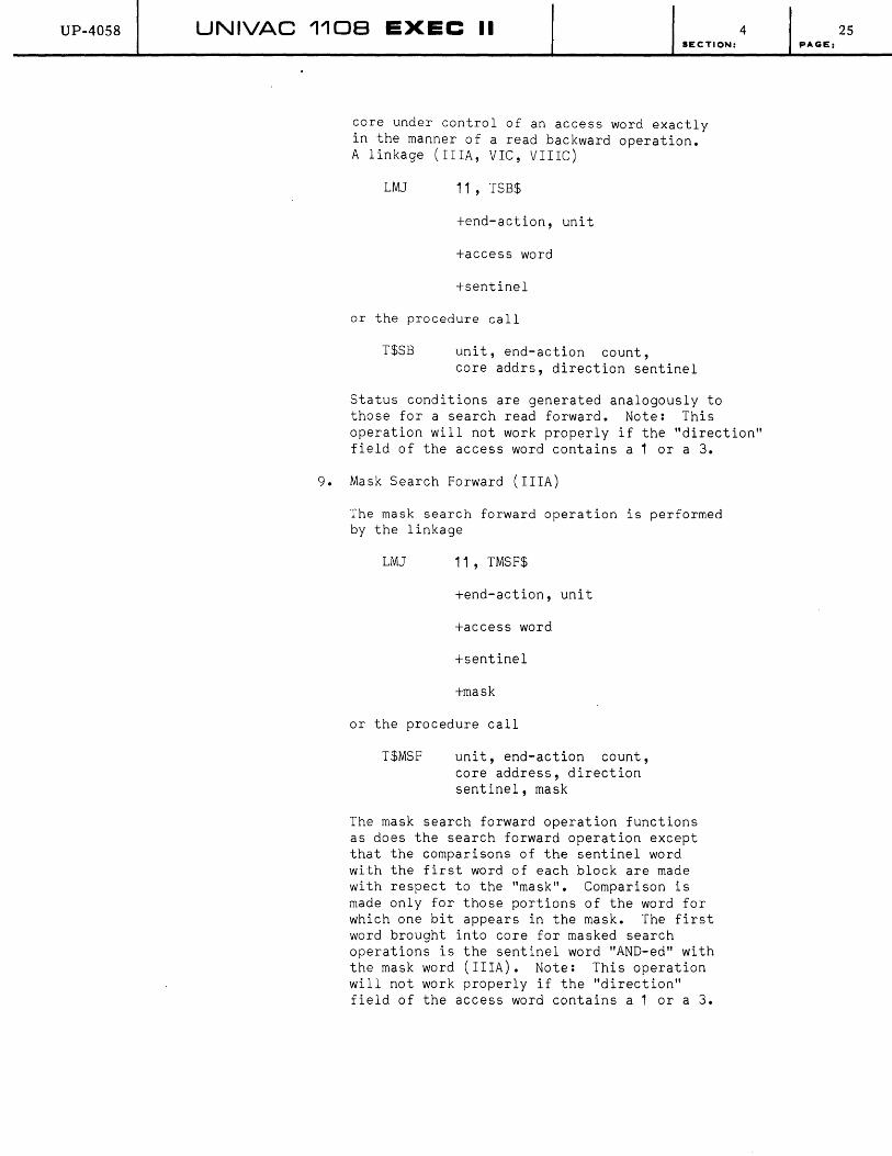
UP-40S8 UNIVAC 1108 EXEC II SECTION:
core under control of an access word exactly in the manner of a read backward operation. A linkage (IlIA, VIC, VIIIC)
LMJ 11 , TSB$
+end-action, unit
+access word
+sentinel
or the procedure call
T$SB unit, end-action count, core addrs, direction sentinel
4
Status conditions are generated analogously to those for a search read forward. Note: This operation will not work properly if the "direction" field of the access word contains a 1 or a 3.
9. Mask Search Forward (IlIA)
The mask search forward operation is performed by the linkage
LMJ 11 , TMSF$
+end-action, unit
+access word
+sentinel
+mask
or the procedure call
T$MSF unit, end-action count, core address, direction sentinel, mask
The mask search forward operation functions as does the search forward operation except that the comparisons of the sentinel word with the first word of each block are made with respect to the "mask". Comparison is made only for those portions of the word for which one bit appears in the mask. The first word brought into core for masked search operations is the sentinel word "AND-ed" with the mask word (IlIA). Note: This operation will not work properly if the "direction" field of the access word contains a 1 or a 3.
25 PAGE:
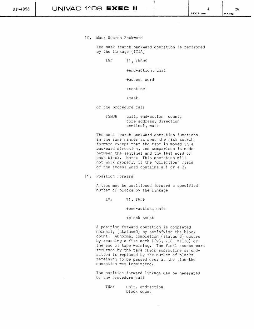
UP-40S8 UNIVAC 1108 EXEC "II SECTION:
10. Mask Search Backward
The mask search backward operation is perfromed by the linkage (IlIA)
LMJ 11 , TMSB$
+end-action, unit
+access word
+sentinel
+mask
or the procedure call
T$MSB unit, end-action count, core address, direction sentinel, mask
The mask search backward operation functions in the same manner as does the mask search forward except that the tape is moved in a backward direction, and comparison is made between the sentinel and the last word of each block. Note: This operation will not work properly if the "direction" field of the access word contains a 1 or a 3.
11 • Position Forward
A tape may be positioned forward a specified number of blocks by the linkage
LMJ 11, TPF$
+end-action, unit
+block count
A position forward operation is completed normally (status=O) by satisfying the block count. Abnormal completion (status=2) occurs by reaching a file mark (IVC, VIC, VIIIC) or the end of tape warning. The final access word returned by the tape check subroutine or endaction is replaced by the number of blocks remaining to be passed over at the time the operation was terminated.
The position forward linkage may be generated by the procedure call
T$PF unit, end-action block count
4 26 PAGE:

UP-4058 UNIVAC 1108 EXEC II SECTION:
12. Position Backward
A tape may be positioned backward a specified number of blocks by the linkage
LMJ 11 , TPB$
+end-action, unit
+block count
A position backward operation is completed normally (status=O} by satisfying the block count. Abnormal completion (status=2) occurs by reaching the physical beginning of tape, or a file mark. The file access word returned by the tape subroutine or end-action is replaced by the number of blocks remaining to be passed over when the operation was terminated.
The position backward linkage may be generated by the procedure call
T$PB unit, end-action block action
13. Position to Start-of-File
A tape may be moved backwards past the last file mark or to the load point, whichever comes first, by the linkage
LMJ 11 , TPS$
+end-action, unit
A stqtus code of 2 will never be generated. The final access word is meaningless.
The position to start-of-file linkage may be generated by the procedure call
T$PS unit, end-action
14. Position to End-of-File
A tape may be positioned forward past a file mark by the linkage
LMJ 11, TPE$
+end-action, unit
A status code of 2 will never be generated. The final access word is meaningless.
4 27 PAGE:

UP-4058 UNIVAC 1108 EXEC II SECTION:
The position to end-of-file linkage may be generated by the procedure call
T$PE unit, end-action
15. Contingency Write
UNISERVO IlIA units provide for a contingency write operation. This operation is inserted automatically by the tape package under certain conditions or may be specified by the programmer with the linkage
LMJ 11 , TCW$
+end-action, unit
or the procedure call
T$CW unit, end-action
The operation terminates by completing the contingency write pattern on tape (status=O), by attempting to write past the end of tape warning (status=2) or by an unrecoverable error (status=3).
A contingency write operation is automatically performed prior to a write (TWR$) or write tape mark (TEF$) provided that the previous operation on that particular tape unit was not any of the following: write (TWR$), write tape mark (TEF$), rewind (TRW$), rewind interlock (TRI$), or contingency write (TCW$). This automatic insertion will handle most of the situations in which a contingency write is needed.
A call to TCW$ for IVC, VIC, or VIIIC units will cause 4 inches of tape to be erased, in a forward direction.
(3) Drum I/O: Normal Mode and Status Codes
(a) Drum Status: DCHK$
Associated with an operation being performed by the package is a status code. It has the values
o Normal completion
In process
2 Abnormal completion
3 Unrecoverable error
4 28 PAGE:

UP-4058 UNIVAC 1108 EXEC II 4
35
Code
SECTION:
In case of an error interrupt, the package will attempt to repeat the operation. If after 20 attempts the error interrupt still persists, a status code of 3 will be set. An abnormal completion code is returned under the following conditions:
On any of the operations, a nonexistent drum address was specified by the user or was reached in the course of the operation.
On a search-type operation, no match was found by the drum synchronizer.
The user may query the status of the most recent drum operation by means of the linkage
LMJ 11, DCHK$
+error/abnormal, in process
If the status is 0, the drum check routine will return following the calling sequence. A return is given to the address specified by "in process" for status code 1, and to that speci fied for "error/abnormal" for status 2 or 3. After any of these returns, the arithmetic registers will be left as
Status code
A1 Final access word
A2 Drum status word
The final access word, if relevant, will contain an indication as to how far the input or output operation proceeded before its termination. The drum status word has the form
30 29 24 23
Status I Drum Address
"Code" indicates the nature of the interrupt causing the termination. This field is useful to the programmer only for abnormal or error status. In the case of abnormal completion, the possible octal values of the code field are:
34 The operation reached a nonexistent drum address
54 The operation began with a nonexistent drum address
04 The end of a drum block (see below) was reached without a match for the block search or block search read operations.
29 pAGE:
o
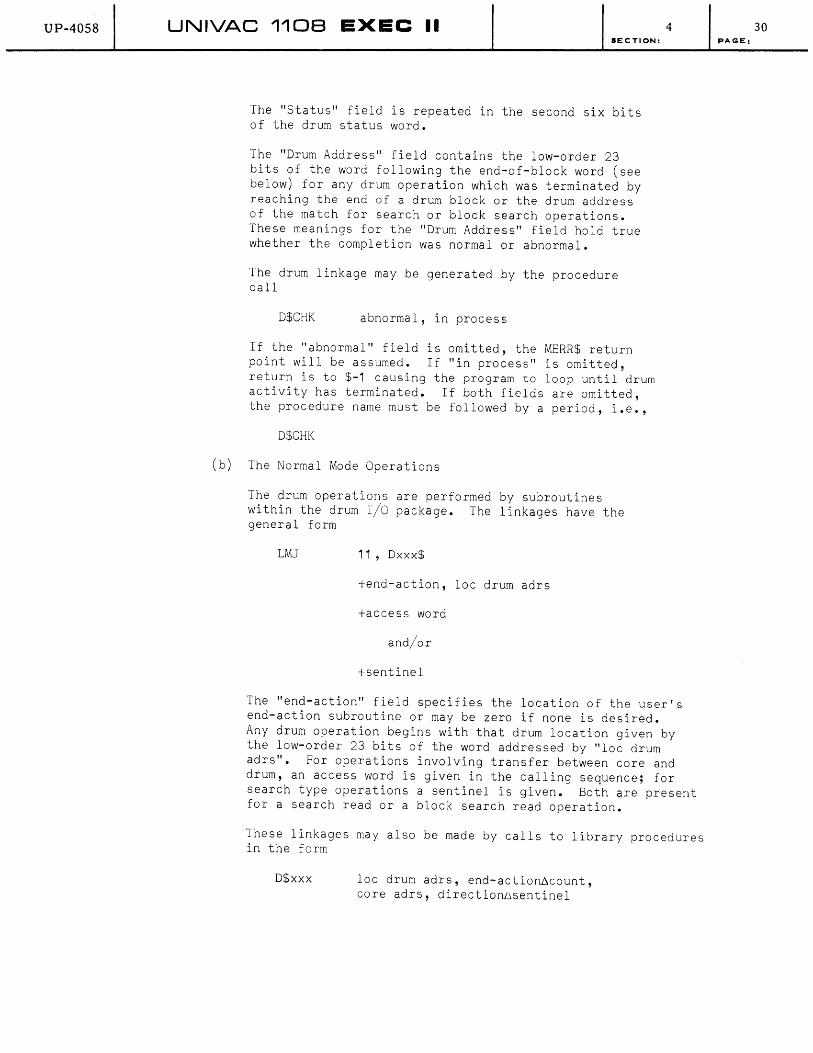
UP-4058 UNIVAC 110B EXEC II SECTION:
The "Status" field is repeated in the second six bits of the drum status word.
The "Drum Address" field contains the low-order 23 bits of the word following the end-of-block word (see below) for any drum operation which was terminated by reaching the end of a drum block or the drum address of the match for search or block search operations. These meanings for the "Drum Address" field hold true whether the completion was normal or abnormal.
The drum linkage may be generated by the procedure call
D$CHK abnormal, in process
If the "abnormal" field is omitted, the MERR$ return point will be assumed. If "in process" is omitted, return is to $-1 causing the program to loop until drum activity has terminated. If both fields are omitted, the procedure name must be followed by a period, i.e.,
D$CHK
(b) The Normal Mode Operations
The drum operations are performed by subroutines within the drum I/O package. The linkages have the general form
LMJ 11 , Dxxx$
+end-action, loc drum adrs
+access word
and/or
+sentinel
4
The "end-action" field specifies the location of the user's end-action subroutine or may be zero if none is desired. Any drum operation begins with that drum location given by the low-order 23 bits of the word addressed by "loc drum adrs". For operations involving transfer between core and drum, an access word is given in the calling sequence; for search type operations a sentinel is given. Both are present for a search read or a block search read operation.
These linkages may also be made by calls to library procedures in the form
D$xxx loc drum adrs, end-action~count, core adrs, directionDsentinel
30 PAGE:

UP-4058 UNIVAC 1108 EXEC II SECTION:
The first of these three lists contains the location of the drum address to be used and the location of the end-action subroutine. If the end-action parameter is omitted, no end-action will occur. The second bit specifies the access word using the notation described in Section 4 B.1 .c. The third list has a single expression which becomes the sentinel. Should an access word or a sentinel not be required for a particular drum operation, the corresponding list is omitted from the procedure call. These procedure calls will generate three or four words.
1. Drum Read
A simple drum read is produced by the linkage
LMJ 11 , DR$
+end-action, lac drum adrs
+access word
The operation is terminated by satisfying the access word (status=O), encountering an invalid drum address (status=2), or by an unrecoverable error (status=3).
The drum read linkage may be generated by the procedure call
D$BR loc drum adrs, end-action6count core adrs, direction
2. Drum Block Read
A drum block consists of an area beginning with a specified drum address and continuing until a word of all one bits (called the end-of-block word) has been passed. The block is considered to include the end-of-block word. The word following an endof-block word may contain in its low-order 23 bits another drum address which may be used for chaining. It is given to the user in the drum status word of any block operation terminated with status=O for a block read, or block search read operation, or with status=2 for a block search or block search read operation.
A drum block may be reached by the linkage
LMJ 11 , DBR$
+end-action, lac drum adrs
+access word
The operation is terminated by satisfying the access word or by reading the end-of-block word
4 31 PAGE:

UP-4058 UNIVAC 1108 EXEC II SECTION:
(both have status=O, the drum status word contains the chain address), encountering an invalid drum address (status=2), or by an unrecoverable error (status=3).
The drum block read linkage may be generated by the procedure call
D$BR loc drum adrs, end-action~count core adrs, direction
3. Drum Search
A drum search consists of comparing each word on drum beginning with the specified drum address until a user-supplied sentinel word is found. A drum search is performed by the linkage
LMJ 11 , DS$
+end-action, loc drum adrs
+sentinel
The operation is terminated by a "find" (status=O, drum status word contains the final address), by encountering an invalid drum address (status=2), or by an unrecoverable error (status=3).
The drum search linkage may be generated by the procedure call
D$S loc drum adrs, end-action~sentinel
4. Drum Block Search
A block search behaves as a drum search except that the search operation is prevented from searching past an end-of-block word.
A block search is performed by the linkage
LMJ 11 , DBS$
+end-action, lac drum adrs
+sentinel
The operation is terminated by a "find" (status=O, drum status word contains the find address), by encountering an end-of-block (status=2, drum status word contains the chain address), by encountering an invalid address (status=2), or by an unrecoverable error (status=3).
The drum block search linkage may be generated by the prodecure call
D$BS lac drum adrs, end-action~sentinel
4 32 PAGE:
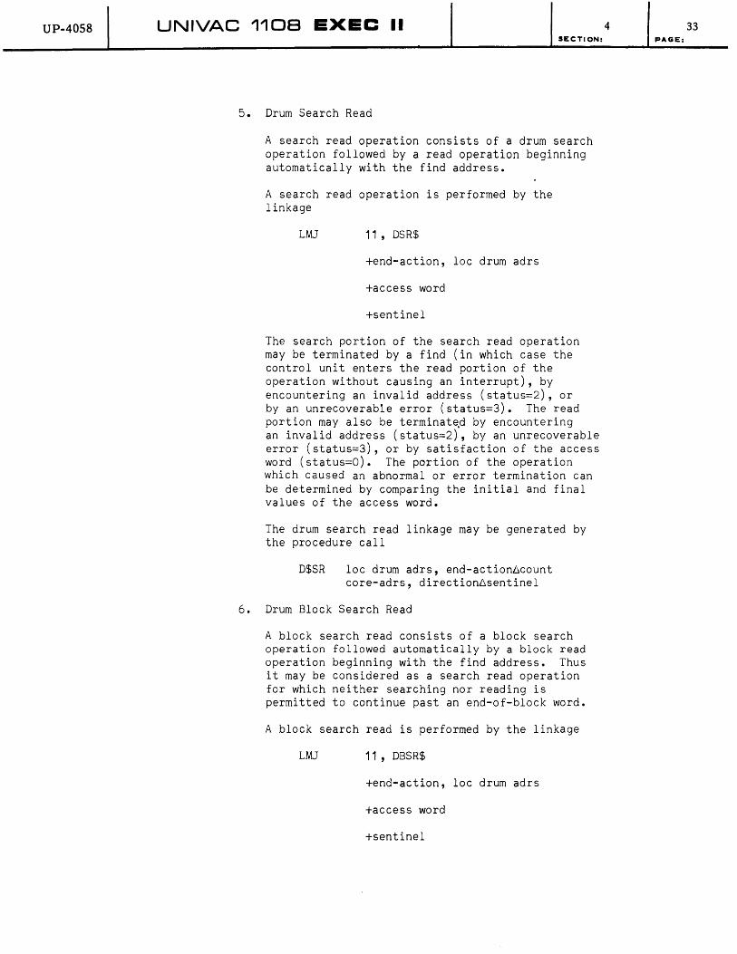
UP-4058 UNIVAC 1108 EXEC II SECTION:
5. Drum Search Read
A search read operation consists of a drum search operation followed by a read operation beginning automatically with the find address.
A search read operation is performed by the linkage
LMJ 11 , DSR$
+end-action, loc drum adrs
+access word
+sentinel
The search portion of the search read operation may be terminated by a find (in which case the control unit enters the read portion of the operation without causing an interrupt), by encountering an invalid address (status=2), or by an unrecoverable error (status=3). The read portion may also be terminat~d by encountering an invalid address (status=2), by an unrecoverable error (status=3), or by satisfaction of the access word (status=O). The portion of the operation which caused an abnormal or error termination can be determined by comparing the initial and final values of the access word.
The drum search read linkage may be generated by the procedure call
D$SR loc drum adrs, end-action~count core-adrs, direction6sentinel
6. Drum Block Search Read
A block search read consists of a block search operation followed automatically by a block read operation beginning with the find address. Thus it may be considered as a search read operation for which neither searching nor reading is permitted to continue past an end-of-block word.
A block search read is performed by the linkage
LMJ 11 , DBSR$
+end-action, loc drum adrs
+access word
+sentinel
4 33 PAGE:
UP-4058 UNIVAC 1108 EXEC II SECTION:
A block search read operation may be terminated by satisfying the access word or encountering the end-of-block word during the read portion (status~O, drum status word contains the chain address), by encountering an invalid address in either portion (status~2), drum status word contains the chain address), or by an unrecoverable error in either portion (status=3).
The drum block search read linkage may be generated by the procedure call
D$BSR
7. Drum Write
loc drum adrs, end-action6count, core adrs, direction6sentinel
A drum write is produced by linkage
LMJ 11, DW$
+end-action, loc drum adrs
+access word
A drum write may be terminated by satisfying the access word (status=O), by encountering an invalid drum address (status=2), or by an unrecoverable error (status=3).
The drum write linkage may be produced by the linkage
D$W loc drum adrs, end-action6count, core adrs, direction
8. Drum End-Action
End-action is fully described in Section 4 B.1 .c. In the particular case of drum end-action, the following quantities are available in registers when the end-action code is entered:
B11 Return point
Ayj Status
A1 Final access word
A2 Drum status word
A3 Location of packet supplied to the packet mode operation (see Section 4 B.1.b.4.)
4 34 PAGE:
UP-40S8 UNIVAC 1108 EXEC II SECTION:
9. Unrecoverable Errors
An error signal from the drum control unit or the drum channel synchronizer which persists after 20 attempts to perform the requested operation will result in error status. In some cases it may be possible to circumvent the error and obtain useful data from the drum. Listed here are codes returned in the drum status word and their abbreviated meanings.
The codes 14, 20, 30, 60, 70, and 74 (octal) represent various failures within the channel synchronizer, the control unit, or the drum itself, from which no recovery is possible.
The code 06 represents a parity error in attempting to read the chain address and may thus be treated as a normal reply if the chain address is not required.
The code 07 represents a parity error on reading in the case of a read operation or the read portion of a search read operation.
The code 64 represents a parity error for a block read, search, block search, block search read, or the search portion of a search read operation. In this case the drum status word contains the drum address of the word which could not be satisfactorily read.
The code 50 indicates that an incorrect signal was received by the drum subsystem from the computer (illegal function). It may result from an error in the hardware, from a seriously incorrect calling sequence, when in the packetmode, or from the drum package itself being overstored.
(4) Drum I/O: ~ Packet Mode (DPKT$)
When the normal mode linkages described above are used, the drum is treated as a single unit in that the drum I/O package will wait until the previous operation is over before initiating a new one. Thus the queuing abilities of the dispatcher are lost if multiple drum files are manipulated by normal mode linkages. To maintain efficient I/O dispatching when multiple drum files are employed, the packet mode may be used. Packet mode operations will in no way interfere with concurrent operations in the normal mode.
4 35 PAGE:
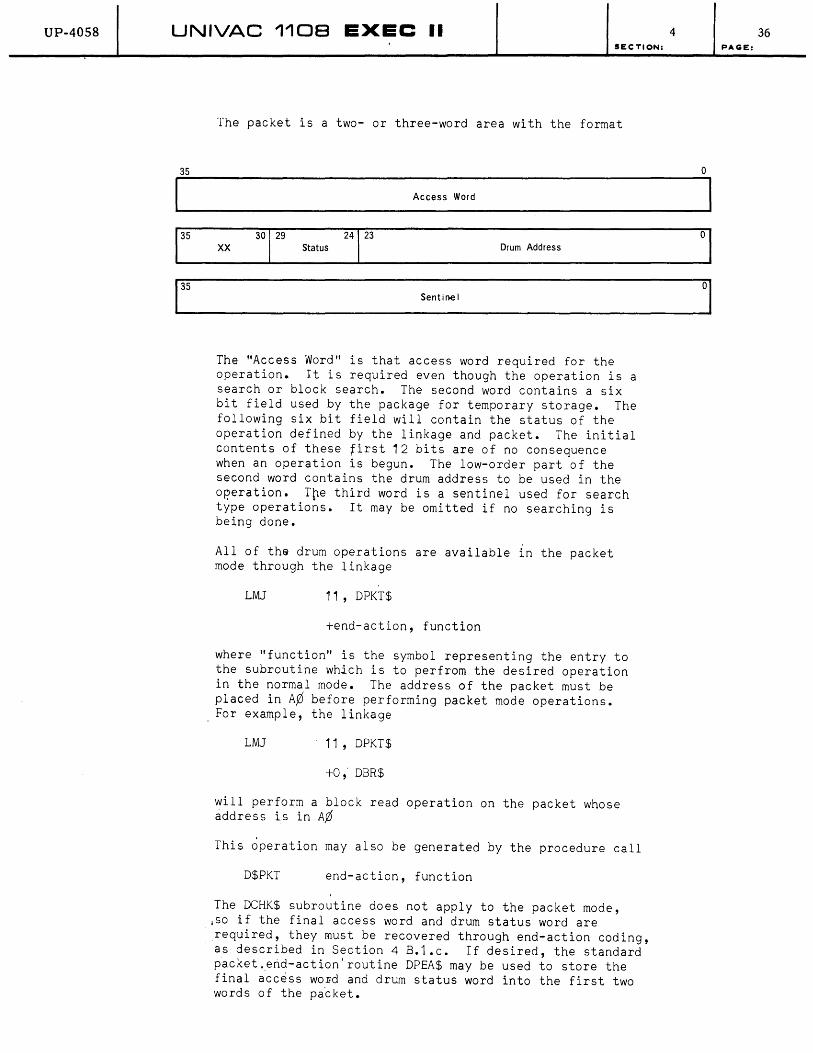
UP-4058 UNIVAC 1108 EXEC II
35
I 1
35
135
SECTION:
The packet is a two- or three-word area with the format
Access Word
XX 30
1
29 Status
24
1
23 Drum Address
Sentioo I
The "Access Word" is that access word required for the operation. It is required even though the operation is a search or block search. The second word contains a six bit field used by the package for temporary storage. The following six bit field will contain the status of the operation defined by the linkage and packet. The initial contents of these first 12 bits are of no consequence when an operation is begun. The low-order part of the second word contains the drum address to be used in the operation. Tne third word is a sentinel used for search type operatio~s. It may be omitted if no searching is being done.
All of the drum operations are available in the packet mode through the linkage
LMJ 11, DPKT$
+end-action, function
where "function" is the symbol representing the entry to the subroutine which is to perfrom the desired operation in the normal mode. The address of the packet must be placed in A¢ before performing packet mode operations. For example, the linkage
LMJ 11 , DPKT$
+0,. DBR$
will perform a block read operation on the packet whose address is in A¢
This operation may also be generated by the procedure call
D$PKT end-action, function
The DCHK$ subroutine does not apply to the packet mode, ,so if the final access word and drum status word are required, they must be recovered through end-action coding, as described in Section 4 B.1.c. If desired, the standard packet .. erid-action'routine DPEA$ may be used to store the final access wOFd and drum status word into the first two words of the pa~ket.
4 36 PAGE:
0
1
01
01
UP-4058 UNIVAC 1108 EXEC II 4 SECTION:
The verification routines described in Section 4 B.1 .c. do not disturb the contents of register A¢ and may be used with the packet mode.
An entry may be made to the drum I/O package from end-action coding in the packet mode. Symbionts may also use the drum r/o package, but only in the packet mode.
Any calling sequence to the drum I/O package may be altered as soon as return is made to the user's program. When using the packet mode, however, the packet itself may not be altered until the operation is complete (that is, when the status field is no longer one).
(5) Block Buffering Package
(a) General Description
The block buffering package is designed as an efficient and general means of communication between core and magnetic tape or drum. A queued buffering scheme is employed which provides any degree of look-ahead that the user deems appropriate and allows buffers to be shared among several files. The buffer package works through the tape and drum input/output packages described earlier in this section.
Communication between the buffer package and the user is accomplished by means of a file description table (see Appendix D 5.). This file description table is a short storage area provided by the user, part of which will be used by the package for storage of addresses, flags, and counters. It contains all the data necessary for manipulation of the file. The location of the file description table serves as the file-name.
Each file is also associated with a core buffer pool which may be shared by other files. The name of the buffer pool for this file is included in the file description area. The use of the buffers in the pool is handled automatically by the package.
The block buffering package is used by the item buffering package (see part 6 of this section). The item buffering package superimposes item advance routines on the package described here. For many users, then, this description is mainly of academic interest since references to it ,in their programs will be made only indirectly through the higher level item buffering packages.
37 PAGE:
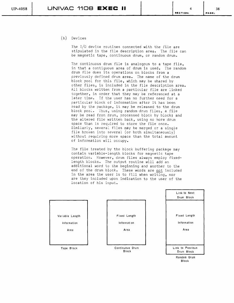
UP-4058 UNIVAC 1108 EXEC II 4 SECTION:
(b) Devices
The I/O device routines connected with the file are stipulated in the file description area. The file can be magnetic tape, continuous drum, or random drum.
The continuous drum file is analogous to a tape file, in that a contiguous area of drum is used. The random drum file does its operations on blocks from a previously defined drum area. The name of the drum block pool for this file, which may be shared by other files, is included in the file description area. All blocks written from a particular file are linked together, in order that they may be referenced at a later time. If the user has no further need for a particular block of information after it has been read by the package, it may be released to the drum block pool. Thus, using random drum files, a file may be read from drum, processed block by block; and the altered file written back, using no more drum space than is required to store the file once. Similarly, several files may be merged or a single file broken into several (or both simultaneously) without requiring more space than the total amount of information will occupy.
The file treated by the block buffering package may contain variable-length blocks for magnetic tape operation. However, drum files always employ fixedlength blocks. The output routine will add an additional word to the beginning and another to the end of the drum block. These words are not included in the area the user is to fill when writing, nor are they included upon indication to the user of the location of his input.
Link to Next
Var iable Length
Information
Area
Tape Block
Fixed Length
Information
Area
Continuous Drum Block
Drum Block
Fixed Length
Information
Area
Link to Previous Drum Block
Random Drum Block
38 PAGE:
UP-4058 UNIVAC 1108 EXEC II SECTION:
(c) Sentinels
The block buffering package provides a generalized method of utilizing sentinel blocks. To avoid dictating to the user the form of his sentinel blocks, he may specify them to the package. This specification is done by supplying two words in the file description area. The first of these is a command which is executed DY the package. This command must load register 12 with some quantity. The package then compares register 12 with the second of the two words. If equality obtains, it is assumed that a sentinel block has been encountered and the appropriate action is taken. The user should be cautioned that the execution of the command occurs during interrupt coding. If any but the simple methods described here are to be used, all rules for interrupt coding, as described in Section 3 B.1 .c. must be observed. When a sentinel block is read, an abnormal return is made from the calling sequence.
Sentinels may be dispensed with altogether, leaving end-of-file detection to the sensing of the end of recorded information for magnetic tape files and the reaching of a certain drum address for continuous or random drum files. The first attempt to obtain a nonexistent block of input will result in an abnormal return.
(d) Input Operations
Four operations are provided for the treatment of input files - open input forward, open input backward, block read, and close input. Each of the linkages requires that register 15 (A3) be preset with the name of the file in the high-order half of the word. For open operations, the low-order half is also used. Procedures associated with the file operations provide the necessary LA command to the load register 15.
1. Open Input File Forward
2. Open Input File Backward
The calling sequences
=-'MJ 11, BOPNF$
and
~MJ 11, BOPNB$
are used to open a file for input in the forward or backward direction, respectively. In either case, register 15 is assumed to be loaded with
release, file name
in which "file name" is the address of the file description table associated with the file.
4 39 PAGE:
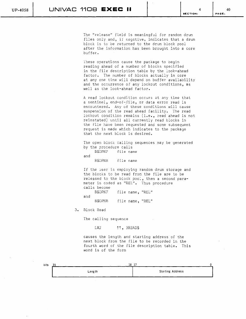
UP-40S8 UNIVAC 1108 EXEC II
3.
SECTION:
The "release" field is meaningful for random drum files only and, if negative, indicates that a drum block is to be returned to the drum block pool after the information has been brought into a core buffer.
These operations cause the package to begin reading ahead of a number of blocks specified in the file description table by the look-ahead factor. The number of blocks actually in core at anyone time will depend on buffer availability and the occurrence of any lockout conditions, as well as the look-ahead factor.
A read lockout condition occurs at any time that a sentinel, end-of~file, or data error read is encountered. Any of these conditions will cause suspension of the read ahead facility. The read lockout condition remains (i.e., read ahead is not reinstated) until all currently read blocks in the file have been requested and some subsequent request is made which indicates to the package that the next block is desired.
The open block calling sequences may be generated by the procedure calls
B$OPNF file name and
B$OPNB file name
If the user is employing random drum storage and the blocks to be read from the file are to be released to the block pool, then a second parameter is coded as "REL". Thus procedure calls become
B$OPNF file name, "REL" and
B$OPNB file name, "REL"
Block Read
The calling sequence
LMJ 11, BREAD$
causes the length and starting address of the next block from the file to be recorded in the fourth word of the file description table. This word is of the form
4
bitsf ... _5 ________ L_e_ng_t_h ________ l_S"'-ll_7 ______ s_ta_r_ti_ng_A_d_dr_e_ss _______ O .... 1
40 PAGE:
UP-4058 UNIVAC 1108 EXEC II SECTION:
The "length" for tape files will be that of the tape block actually read. If the block was actually longer than the maximum expressed in word 8 of the file description table, the remainder of the block will be lost. The "starting address" will always be the first
4
location of the block as it resides in a core buffer, regardless of the direction in which the file is being read.
A block may be read from a file by the procedure call
B$READ file name
By adding a second parameter "abnorm", i.e.
B$READ file name, abnorm
the procedure will generate an NOP command following the calling sequence. This mqy be used to specify individual abnormal returns for each call' on th~ package. To use this facility, a suitable entry must be made in the file description area as discussed in paragraph h of this section.
4. Close Input File
The calling sequence
LMJ' 11 , BCLSR$
causes all currently reserved buffers for this file to be released. In addition, it sets the file to a closed status. No rewind occurs for tape files. The close input calling sequence may be generated by the procedure call
B$CLSR file name
(e) Outout Operations
Three operations are provided for the treatment of output files - open output, block write, and close output. As for the input operations, each of the linkages requires that register 15 be preset with the file-name. This presetting is generated by the corresponding procedure calls.
1. Open Output File
The calling sequence
LMJ 11, BOPNW$
conditions the package to receive blocks of information for this file· and obtains a buffer for the user. The location an~ length of the available buffer are placed in the fourth word
41 PAGE:

UP-4058 UNIVAC 110B EXEC II SECTION:
of the file description table before return is made. The linkage is generated by the procedure call
B$OPNW file name
2. Block Write
The calling sequence
LMJ 11 , BWRIT$
transmits a loaded buffer to the output device specified in the file description table. A queue of blocks waiting for the device is maintained. Whenever the corresponding channel becomes free, the next block waiting is written.
For magnetic tape files the length of the block written will be taken from the left half of the fourth word in the file description area. This field may be altered by the user if a block of less than the maximum size is to be written. Magnetic drum files, whether continuous or random, will always be written with the maximum block size specified in the eighth word of the file description area.
Following return from the BWRIT$ subroutine, word 4 will contain the location and length of a new buffer. Information may be stored into the buffer immediately.
A block may be written to a file by means of the procedure call
B$WRIT file name
3. Close Output File
When all blocks have been written to an output file, it must be closed. This is accomplished by the linkage
LMJ 11, BCLSW$
or the procedure call
B$CLSW file name
The block buffering package releases the last buffer obtained for the user, delays until all blocks which were waiting for the device have written out, and sets the file to closed status. No rewind occurs for tape files.
4 42 PAGE:
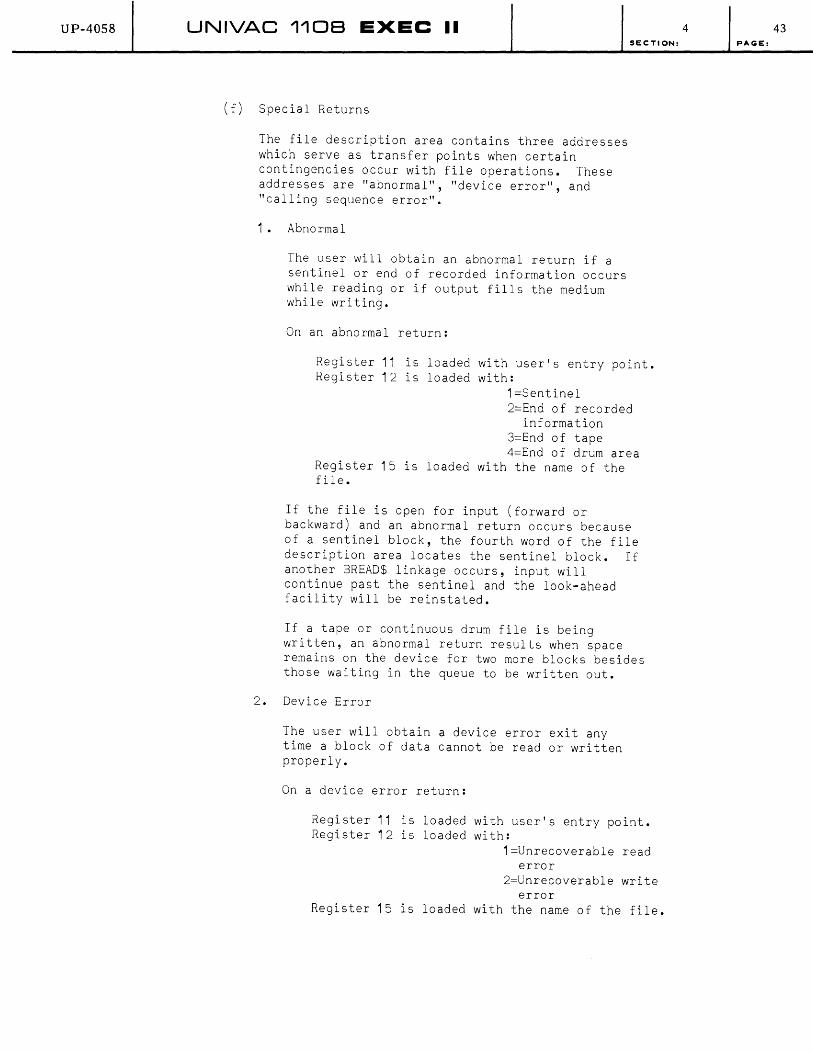
UP-40S8 UNIVAC 1108 EXEC II
(f) Special Returns
The file description area contains three addresses which serve as transfer points when certain contingencies occur with file operations. These addresses are "abnormal", "device error", and "calling sequence error".
1. Abnormal
The user will obtain an abnormal return if a sentinel or end of recorded information occurs while reading or if output fills the medium while writing.
On an abnormal return:
SECTION:
Register 11 is loaded with user's entry point. Register 12 is loaded with:
1 =Sentinel 2=End of recorded
information 3=End of tape 4=End of drum area
Register 15 is loaded with the name of the file.
If the file is open for input (forward or backward) and an abnormal return occurs because of a sentinel block, the fourth word of the file description area locates the sentinel block. If another BREAD$ linkage occurs, input will continue past the sentinel and the look-ahead facility will be reinstated.
If a tape or continuous drum file is being written, an abnormal return results when space remains on the device for two more blocks besides those waiting in the queue to be written out.
2. Device Error
The user will obtain a device error exit any time a block of data cannot be read or written properly.
On a device error return:
Register 11 is loaded with user's entry point. Register 12 is loaded with:
1=Unrecoverable read error
2=Unrecoverable write error
Register 15 is loaded with the name of the file.
4 43 PAGE:

UP-4058 UNIVAC 1108 EXEC II
(g)
SECTION:
3. Calling Sequence Error
There are two types of calling sequence errors. The first occurs when one attempts an operation on a file which is in the wrong status, e.g., opening a file already open, writing a file opened for reading, incompatible buffer and block size in the case of random drum buffer size and drum block size, or insufficient area to write when file is opened. The second pertains to random drum. If a drum block is released which does not belong to the drum block pool, a calling sequence error will result.
On a calling sequence error return:
Register 11 is loaded with user's entry point. Register 12 is loaded with:
1=File mode error 2=Improper drum
release Register 15 is loaded with the name of the file.
Buffer Pools and Drum Block Pools
A buffer pool is a collection of areas of core storage which are available to be used as input/output areas by one or more files. When a buffer is being used by a file, it is not currently a part of the pool. The block buffering package removes a buffer from the pool when an input/output area is needed and returns it to the pool when there is no longer any need for the information.
A single word is used to control a buffer pool. Its address serves as the name of the pool and is referenced from the file description ar~a. This word has the form
Size of Buffer in the Pool
18
Location of First Avai lable Buffer
18
The right half of the word refe~ences the first word of the first available buffer. The right half of the first word of this buffer references in turn the first word of the next available buffer, and so forth. The last buffer in the chain has a zero for its "pointer". Following each "pointer" word is a buffer I/O access word and the 9uffer. Thus "buffer size" includes two control words in addition to the I/O block size.
4 44 PAGE:

UP-4058 UNIVAC 1108 EXEC II SECTION:
1. BPOOL$
The subroutine BPOOL$ may be used to convert an area of storage into a buffer pool. The linkage to this subroutine is:
LMJ 11, BPOOL$
+buffer size, name of pool
+length, address
"name of pool" is the address of the buffer pool content;
"buffer size" is the number of words each buffer is to contain
"address" is the starting address of the core area; and
"length" is the length of this core area.
The linkage is generated by the procedure call
B$POOL
2. BJOIN$'
name of pool, buffer size address, length
A second subroutine is available to attach a core area to an already existing buffer pool. It has the linkage
LMJ 11 , BJOIN$
+0, name of pool
+length, address
and the corresponding procedure call
B$JOIN name of pool address, length
In either of the subroutines BPOOL$ and BJOIN$, as many buffer areas will be treated as the available core area can hold.
The procedure call
name of pool B$GPUL number of buffers, buffer size
will generate a buffer pool control word and create at assembly time a pool of "number of buffers" areas each consisting of "buffer size" words. A buffer pool created in this manner need not be initialized by using BPOOL$.
4 45 PAGE:
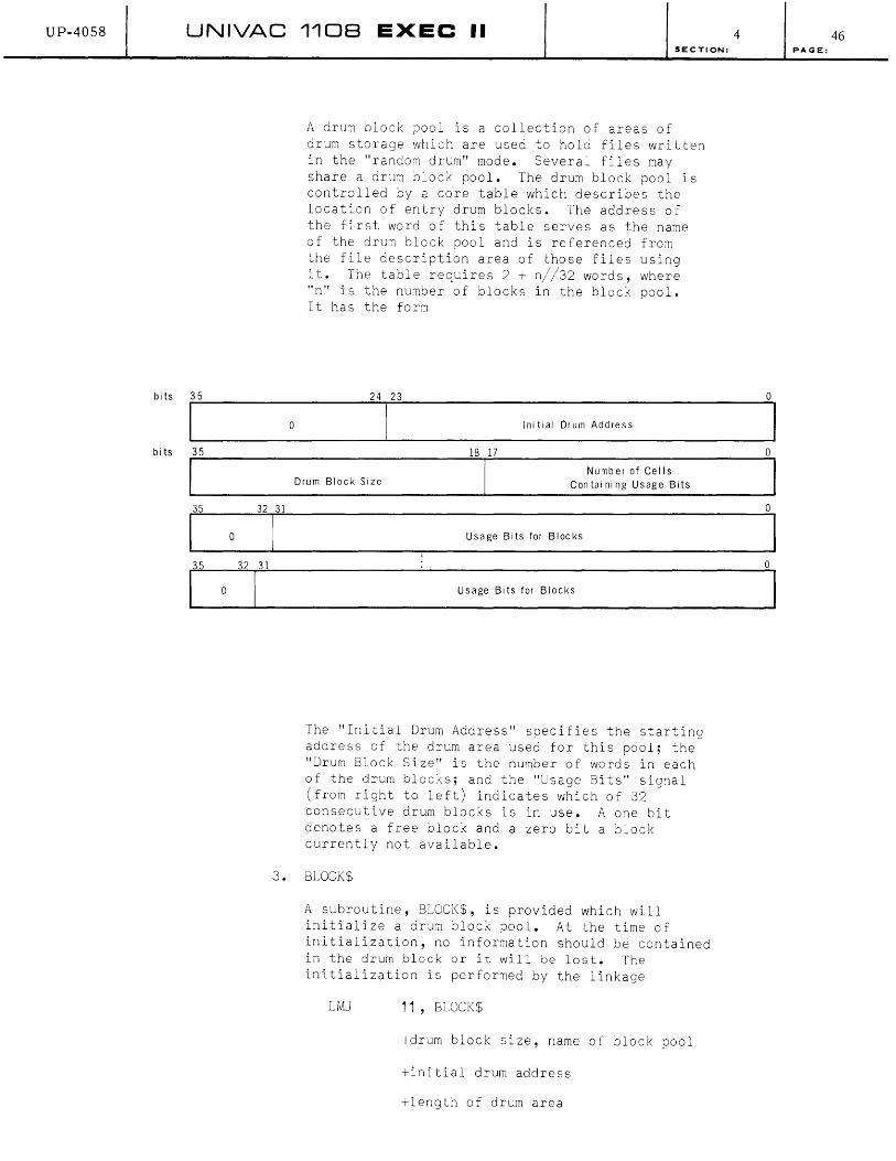
UP-4058 UNIVAC 1108 EXEC II SECTION:
A drum block pool is a collection of areas of drum storage which are used to hold files written in the "random drum" mode. Several files may share a drum block pool. The drum block pool is controlled by a core table which describes the location of entry drum blocks. The address of the first word of this table serves as the name of the drum block pool and is referenced from the file description area of those files using it. The table requires 2 + n//32 words, where "n" is the number of blocks in the block pool. It has the form
4
bits ~3~5 ____________________ ~2~4~2~3 ______________________________________________ --,O
I 0 I Ini lial O<UITI Add,e" I bits ~3~5 __________________________________ ~1~8~17~ ________________________________ ~O
a
35
Drum Block Size Number of Cells
Con tai ni ng Usage Bits
Usage Bits for Blocks
Usage Bits for Blocks
The "Initial Drum Address" specifies the starting address of the drum area used for this pool; the "Drum Block Size" is the number of words in each of the drum blocks; and the "Usage Bits" signal (from right to left) indicates which of 32 consecutive drum blocks is in use. A one bit denotes a free block and a zero bit a block currently not available.
3. BLOCK$
A subroutine, BLOCK$, is provided which will initialize a drum block pool. At the time of initialization, no information should be contained in the drum block or it will be lost. The initialization is performed by the linkage
LMJ 11, BLOCK$
+drum block size, name of block pool
+initial drum address
+length of drum area
a
46 PAGE:
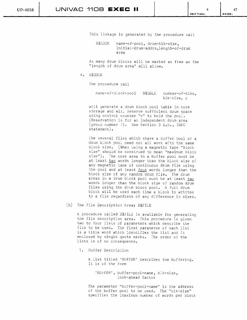
UP-40S8 UNIVAC 1108 EXEC II SECTION:
This linkage is generated by the procedure call
B$LOCK name-of-pool, drum-blk-size, initial-drum-addrs,length-of-drum area
As many drum blocks will be marked as free as the "length of drum area" will allow.
4. B$GBLK
The procedure call
name-of-block-pool B$GBLK number-of-blks, blk-size, c
will generate a drum block pool table in core storage and will reserve sufficient drum space using control counter "c" to hold the pool. (Reservation is for an independent drum area (group number 7). See Section 3 B.5., INFO statement).
The several files which share a buffer pool or a drum block pool need not all work with the same block size. (When using a magnetic tape "block size" should be construed to mean "maximum block size"). The core area in a buffer pool must be at least two words longer than the block size of any magnetic tape of continuous drum file using the pool and at least four words longer than the block size of any random drum file. The drum areas in a drum block pool must be at least two words longer than the block size of random drum files using the drum block pool. A full drum block will be used each time a block is written to a file regardless of any difference in sizes.
(h) The File Description Area; B$FILE
A procedure called B$FILE is available for generating the file description area. This procedure is given two to four lists of parameters which describe the file to be used. The first parameter of each list is a title word which identifies the list and is enclosed by single quote marks. The order of the lists is of no consequence.
1. Buffer Description
A list titled 'BUFFER' describes the buffering. It is of the form
'BUFFER', buffer-pool-name, blk-size, look-ahead factor
The parameter "buffer-pool-name" is the address of the buffer pool to be used. The "blk-size" specifies the (maximum number of words per block
4 47 PAGE:
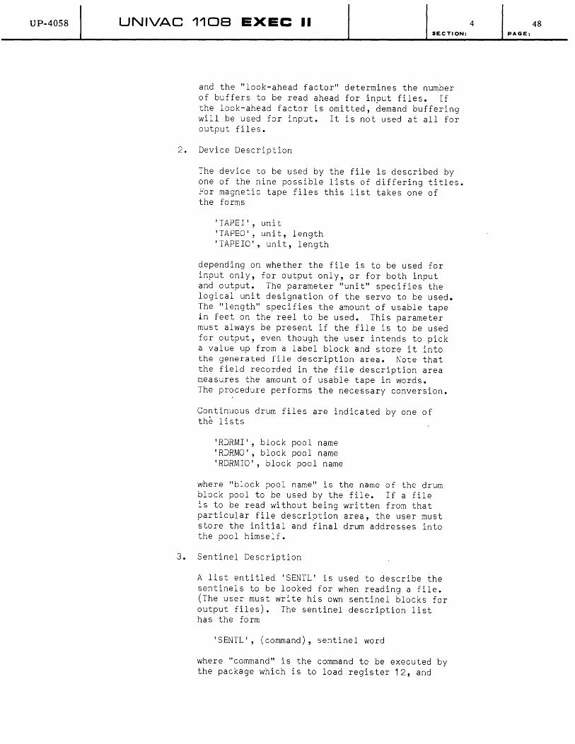
UP-40S8 UNIVAC 1108 EXEC II SECTION:
and the "look-ahead factor" determines the number of buffers to be read ahead for input files. If the look-ahead factor is omitted, demand buffering will be used for input. It is not used at all for output files.
2. Device Description
The device to be used by the file is described by one of the nine possible lists of differing titles. For magnetic tape files this list takes one of the forms
'TAPEI', uni t 'TAPEO', unit, length 'TAPEIO', unit, length
depending on whether the file is to be used for input only, for output only, or for both input and output. The parameter "unit" specifies the logical unit designation of the servo to be used. The "length" specifies the amount of usable tape in feet on the reel to be used. This parameter must always be present if the file is to be used for output, even though the user intends to pick a value up from a label block and store it into the generated file description area. Note that the field recorded in the file description area measures the amount of usable tape in words. The procedure performs the necessary conversion.
Continuous drum files are indicated by one of the lists
'RDRMI', block pool name 'RDRMO', block pool name 'RDRMIO', block pool name
where "block pool name" is the name of the drum block pool to be used by the file. If a file is to be read without being written from that particular file description area, the user must store the initial and final drum addresses into the pool himself.
3. Sentinel Description
A list entitled 'SENTL' is used to describe the sentinels to be looked for when reading a file. (The user must write his own sentinel blocks for output files). The sentinel description list has the form
'SENTL', (command), sentinel word
where "command" is the command to be executed by the package which is to load register 12, and
4 48 PAGE:

UP-4058 UNIVAC 1108 EXEC II SECTION:
"sentinel word" is the value to which register 12 will be compared in order to detect a sentinel. The sentinel list may be omitted entirely. The result is that the check for a sentinel will always fail.
4. Special Returns
The user may optionally supply a list of the form
'RETURN', abnormal, device error, calling 5equence error
for the specification of the special returns. The parameters are the addresses to which a jump occurs when the contingencies discussed above occur. By encoding the abnormal return as
(J *1, 11)
and writing the instruction
NOP address
following each call on BREAD$ or BWRIT$ which might produce an abnormal return, the user can effect a separate abnormal return for each call he makes. Library routines are provided for the treatment of device and calling sequence errors. These routines are called BDVER$ and BCSER$, respectively. They will produce a message identifying the file and particular reference to the call which produced the error, as appropriate, and jump to MERR$. Omitted parameters will automatically be supplied by the procedure. If "abnormal" is omitted, it will be filled in as (J *1, 11). Device and call ing sequence errors are filled in as BDVER$ and BCSER$. If the 'RETURN' list is omitted entirely, all three substitutions will occur.
Suppose it is desired to write a tape file of 400 word blocks on unit "Q" using the block buffering package. Buffer pool POOL is to be used and no abnormal returns will occur. The file d~scription area may be generated by the procedure call
B$FILE 'BUFFER', POOL, 400 'TAPEO', , 'Q', 600
Suppose now that a random drum file of 256 word blocks is to be used for both input and output. The buffer pool is still POOL and the drum block pool is called BLOCKS. When reading, three advance blocks are to be made available. A sentinel should consist of a word of all periods
4 49 pAGE:
UP-40S8 UNIVAC 1108 EXEC II SECTION:
appearing in the third word of a block. End-of-file (abnormal) processing occurs at EOF. In this case the file description area would be generated by the procedure call
B$FILE 'SENTL', (L 1 2,1 ,1 2) , , •••••• '
'RDRMIO', BLOCKS 'BUFFER', POOL,256,3 ; 'RETURN' ,EOF
(i) Format of the File Description Area
For those who prefer to create their own areas, the precise format of the file description table and the purpose of each of its fields is explained in Appendix D 5. Those fields enclosed in parentheses are filled in by the package itself and are normally not of concern to the user.
(6) Label and Item Package
(a) General Description
The label and item handling routines provide an efficient means of treating multireel data files as
4
well as multifile reels for tape and for drum. This package will initiate or close input or output files, identify or check labels, write or test for end-of-file or end-of-reel sentinels, or specify a bypass of unneeded data and read or write items. This routine will write LION-compatible tapes and will read LION-produced tapes.
The labeling and item routines make use of the block buffering package. The communication region is the file description area plus seven additional words, illustrated in Appendix D 6.a. Each of the linkages requires that register 15 (A3) contain the name of the file in the high-order half of the word.
The length of a label block, a bypass sentinel, and the maximum length of a data block is determined by the Block Size as found in the file description area. A Block Size of less than 240 words produces label and bypass sentinels of 120 words. Label blocks of 120 words may only overwrite the label block of the first file or the end-of-file block for the last file on tape. A block of 240 words or more will produce label and bypass sentinels of 240 words which may overwrite any sentinel. End-of-file and end-of-reel sentinels are always of a fixed 50 word length for tape.
The label routine writes a label block as the first block on each reel of tape and at the beginning of each reel of a multireel file. In the case of multireel files, an end-of-reel sentinel is recorded at the end of each tape.
50 PAGE:
UP-4058 UNIVAC 1108 EXEC II
Data blocks are written or read through the item handling routines as either variable-length or fixed-length items as determined by the IS para-
SECTION:
meter in the file description area. The package maintains control of output items between the time they are received by the object program until the time they are written on tape or drum. Input items are held in core buffer areas until requested by the object program. When the last item in a core buffer has been received by the object program that buffer is released to the buffer pool. The minimum length data block that may be written on tape is 120 words. There are no minimum restrictions for writing drum files. The updating of either the amount of usable tape or the amount of available drum area is performed automatically by the package.
(b) There are seven operations provided for the treatment of output files - open output, extend output, locate item, write item, write bypass sentinel, close file and close reel. Each of the linkages requires that register 15 (A3) be present with the file name.
The file description area provides an end-of-reel exit (EORW) for output tapes. This exit is taken whenever the number of remaining words on tape is less than the Buffer Size. If this exit is set to zero, the following standard end-of-reel procedure is followed:
An end-of-reel sentinel is written. The tape is rewound with interlock. An alternate tape is checked and a label block is written. Control is returned to object program.
When the end-of-reel exit is taken, it is assumed that the object program will make a call to the close reel routine, ICREW$. The end-of-reel exit is given before the last item has been written. The user must therefore return control to the package. The return point is provided in X11.
1. Open Output File
The linkage
LMJ 11, IOWT$
opens the file whose name is contained in the right half word of register 15 (A3) and writes a label block. Before a label is to be written on tape,
4
the tape is checked to determine if it can be overwritten. If it cannot - a label error exit is given. It is the responsibility of the object program to insure that the tape is positioned properly.
51 PAGE:
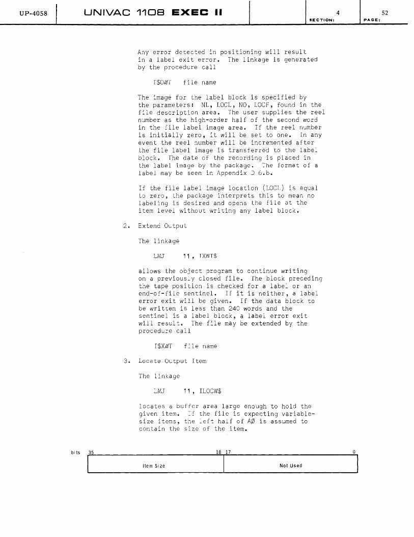
UP-4058
bi ts
UNIVAC 1108 EXEC II SECTION:
Any error detected in positioning will result in a label exit error. The linkage is generated by the procedure call
I$OWT file name
The image for the label block is specified by the parameters: NL, LOCL, NO, LOCF, found in the file description area. The user supplies the reel number as the high-order half of the second word in the file label image area. If the reel number is initially zero, it will be set to one. In any event the reel number will be incremented after the file label image is transferred to the label block. The date of the recording is placed in the label image by the package. The format of a label may be seen in Appendix D 6.b.
If the file label image location (LOCL) is equal to zero, the package interprets this to mean no labeling is desired and opens the file at the item level without writing any label block.
2. Extend Output
The linkage
LMJ 11, IXWT$
allows the object program to continue writing on a previously closed file. The block preceding the tape position is checked for a label or an end-of-file sentinel. If it is neither, a label error exit will be given. If the data block to be written is less than 240 words and the sentinel is a label block, a label error exit will result. The file may be extended by the pro'cedure call
I$XWT file name
3. Locate Output Item
The linkage
LMJ 11, ILOCW$
locates a buffer area large enough to hold the given item. If the file is expecting variablesize items, the left half of A~ is assumed to contain the size of the item.
Item Size Not Used
4 52 PAGE:
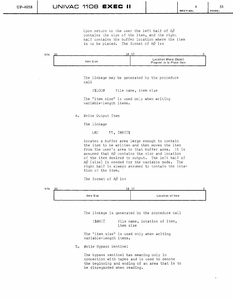
UP-40S8
bits
UNIVAC 1108 EXEC II SECTION:
Upon return to the user the left half of A¢ contains the size of the item, and the right half contains the buffer location where the item is to be placed. The format of A¢ is:
18 17
Item Si ze Location Where Object
Program is to Place Item
The linkage may be generated by the procedure call
I$LOCW file name, item size
The "item size" is used only when writing variable-length items.
4. Write Output Item
The linkage
LMJ 11, IWRIT$
locates a buffer area large enough to contain the item to be written and then moves the item from the user's area to that buffer area. It is assumed that A¢ contains the size and location of the item desired to output. The left half of A¢ (size) is needed for the variable mode. The right half is always assumed to contain the location of the item.
The format of A¢ is:
4
°
bi ts 1 ... 3_5 ________ 1 t e_m_S_i z_e _______
18
.......... ll_7 ______ Lo_c_a_t_io_n _O_f _It_e_m ______ O ... 1
The linkage is generated by the procedure call
I$WRIT file name, location of item, item size
The "item size" is used only when writing variable-length items.
5. Write Bypass Sentinel
The bypass sentinel has meaning only in connection with tapes and is used to denote the beginning and ending of an area that is to be disregarded when reading.
53 PAGE:

UP-4058 UNIVAC 110B EXEC II SECTION:
The linkage
LMJ 11, IBYPS$
causes any unrecorded items to be written and follows the last data block with a bypass sentinel. It is the user's responsibility to write the data between bypass sentinels and update the available tape count. This may be most easily accomplished by using either the block buffering or the item routines, since the updating is done automatically. After having written the intervening information the user can either initiate the file for more items by the linkage
LMJ 11, IBYPS$
or he may close the file completely by the linkage
LMJ 11, ICLW$
The file remains open at block level, however. The format of a bypass sentinel is shown in Appendix D. 6. c. A bypass sentinel may be written by the procedure call
I$BYPS file name
6. Close File
The close file terminates the writing of an output file and is meaningful for both drum and tape files.
The linkage
LMJ 11, ICLW$
causes any unrecorded items to be written and an end-of-file sentinel to be recorded following the last data block. If the device is tape, the REW option as found in the file description area is taken. This option indicates whether the tape should not be rewound, should be rewound, or should be rewound with interlock. The format of the end-of-file sentinel is shown in Appendix D. 6. d. The file may be closed by the procedure call
I$CLW file name
7. Close Reel
The close reel terminates writing on a tape reel and initiates action on an alternate reel. This call is meaningful only for multireel tape files.
4 54 PAGE:

UP-4058 UNIVAC 1108 EXEC II
The close reel linkage
LMJ 11, ICREW$
does the following:
Writes any unrecorded items; Writes an end-of-reel sentinel; Takes the tape rewind option (REW);
SECTION:
Checks an alternate tape and writes a label block; and Returns control to the object program.
The format of the end-of-reel sentinel is shown in Appendix D. 6. c. A reel may be closed by the procedure call
I$CREW file name
(c) Six operations are provided for the treatment of input files--open input forward, open input backward, locate item, read item, close reel, close file.
The item handlers locate or read items until a sentinel block is discovered. For an end-of-file or label, an end-of-file exit is given. However, when a bypass sentinel is encountered, all information between it and the next sentinel is disregarded. If the next sentinel is another bypass sentinel the routine continues. Whenever an end-of-reel sentinel is encountered and if the end-of-reel exit (EORR) is zero in the file description area, the routine performs the following standard reel ending procedure:
Rewind current tape without interlock; Read and check the alternate tape; and Obtain the next item and return control to object program.
When the user provides an end-of-reel exit the routine transfers control to this location. B11 contains the return point to the proper location in the Label Package. It is the responsibility of the user end-of-reel routine to call ICRER$ before returning to the Label Package. After the label has been checked, ICRER$ returns with the location and number of free words in A¢. The close reel routine uses the REW option as found in the file description area. Otherwise, it is essentially the same as the standard reel ending procedure.
4 55 PAGE:
UP-4058 UNIVAC 1108 EXEC II SECTION;
1. Open File Forwards
The linkage
LMJ 11, IOPNF$
opens the file whose name is contained in the high-order half word of register 15 (A3). It is the responsibility of the object program to ensure that the input tape is positioned at the appropriate label block. The file label is compared to the label image provided by the object program. The location and length is controlled by the parameters provided in the file description area. Checking of the date may be omitted by setting the date word in the image to zero. All checking of labels may be omitted by setting the file label images location (LOCL) to zero. In this case the file is opened at the item level expecting the first block read to be a data block.
The following console message will be type out when a label error is detected on an input file.
LABEL ERROR ffffff UNIT n (NO OR GO)
ffffff represents the file name.
n represents the logical unit used to process the file.
A GO response to this message will cause the label error to be ignored, and file processing continues.
A NO response re-interrogates Unit n for another label. The tape should be changed before the NO response is given. If the newly mounted tape also contains a label error, the above message will again by typed out.
The input buffer must be equal to or greater than the block length as found in the label block. Any discrepancy in the label checking or in the position of the tape results in a label error exit.
2. Open File Backwards
The linkage
LMJ 11, IOPNB$
opens the file to read items backwards. The label check procedure is omitted for backward reading. However, the object program must ensure that the tape is positioned at a label block or at an end-of-file sentinel.
4 56 PAGE:

UP-4058 UNIVAC 1108 EXEC II
bits 35
SECTION:
The linkage is generated by the procedure call
I$OPNB file name
3. Locate Input Item
The linkage
LMJ 11, ILCOR$
locates the next item in the buffer area. The location and size of the input item is presented to the object programs in control register 12 (A¢). The format of A¢ is:
18 17
4
o ----------------------------------~~--------------------------------~
bits 35
Number of Words in Item Location 01 Item
The item may be located by the procedure call
ISLOCR file name
4. Read Input Item
The linkage
LMJ 11, IREAD$
is used to locate the next item and then move this item into the user's area. It is assumed that the object program presents to the routine in register 12 (A¢) the location where the item is to be transferred. The format of A¢ is:
18 17 ° ~--------------------------------~---------------------------------, (Not Used)
Location Where Item is to be Moved
In turn the location and size of the input item is presented to the object program in A¢. The format of A¢ is:
bits .:,3::,.5 _____________________________ ---.,;1:.,:8-r-:1:.:.7 _____________________________ --,O
Number of Words in Item Location Where Item
is to be Moved
The item may be read by the procedure call
I$READ file name, location
57 PAGE:

UP-40S8 UNIVAC 1108 EXEC II
5. Close File
The linkage
LMJ 11, ICLR$
terminates all reading of the file as defined in register 15 (A3). If the device is tape, the REW option will be used.
The file may be closed by the procedure call
I$CLR file name
6. Close Reel
This routine has meaning only for multireel files. The linkage
LMJ 11, ICRER$
SECTION:
terminates all action on the present tape unit as defined by register 15 and initializes an alternate tape for subsequent action. The standard reel ending procedure is used in conjunction with the REW option.
The reel may be closed by the procedure call
I$CRER file name
(d) Find File
The linkage
LMJ 11, IFIND$
searches a multifile reel for the file defined in the file description table and positions the tape past the label block of the specified file.
If an end-of-file sentinel is encountered before the file is found, the tape is rewound and searched again. If the file is not found on the second pass, a label error exit is given. A file may be found by the procedure call
I$FIND file name
c. Direct r/o
(1) General Information
Under the EXEC II system, card and print I/O are normally controlled by symbiont-cooperative systems rather than by the worker program (see Section 4 B.1 .a.). For magnetic tape and drum, special packages are provided which permit somewhat more control by the worker program ( see Sec t ion 4 3. 1 • b. ) • For pap e r tap e, the wo r k e r
4 58 PAGE:
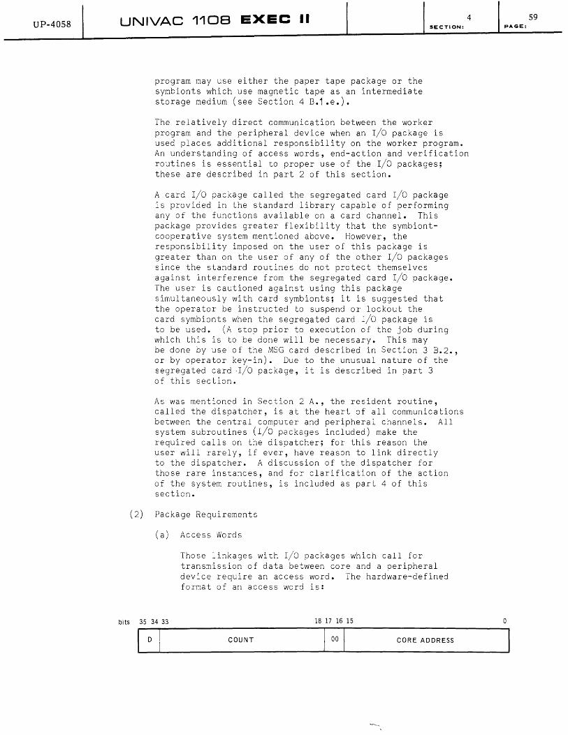
UP-4058 UNIVAC 1108 EXEC II
program may use either the paper tape package or the symbionts which use magnetic tape as an intermediate storage medium (see Section 4 B.1 .e.).
SECTION:
The relatively direct communication between the worker program and the peripheral device when an r/o package is
4
used places additional responsibility on the worker program. An understanding of access words, end-action and verification routines is essential to proper use of the r/o packages; these are described in part 2 of this section.
A card r/o package called the segregated card r/o package is provided in the standard library capable of performing any of the functions available on a card channel. This package provides greater flexibility that the symbiontcooperative system mentioned above. However, the responsibility imposed on the user of this package is greater than on the user of any of the other r/o packages since the standard routines do not protect themselves against interference from the segregated card r/o package. The user is cautioned against using this package simultaneously with card symbionts; it is suggested that the operator be instructed to suspend or lockout the card symbionts when the segregated card r/o package is to be used. (A stop prior to execution of the job during which this is to be done will be necessary. This may be done by use of the MSG card described in Section 3 B.2., or by operator key-in). Due to the unusual nature of the segregated cardr/O package, it is described in part 3 of this section.
As was mentioned in Section 2 A., the resident routine, called the dispatcher, is at the heart of all communications between the central computer and peripheral channels. All system subroutines (I/O packages included) make the required calls on the dispatcher; for this reason the user will rarely, if ever, have reason to link directly to the dispatcher. A discussion of the dispatcher for those rare instances, and for clarification of the action of the system routines, is included as part 4 of this section.
(2) Package Requirements
(a) Access Words
bits 35 34 33
Those linkages with r/o packages which call for transmission of data between core and a peripheral device require an access word. The hardware-defined format of an access word is:
18 17 16 15
COUNT CORE ADDRESS
59 PAGE:
o

UP-4058 UNIVAC 1108 EXEC II SECTION:
The field "core address" contains the address of the core location at which data transmission is to begin; "count" is the number of words (characters for the console channel) to be transmitted; and "D" is the direction indicator. The direction indicator specifies whether the "core address" field is to be incremented, decremented, or left unchanged as successive words
4
are transmitted. The "count" field is always decremented, and transmission stops when it becomes zero. Values for the "D" field are (binary notation)
00 increment
10 decrement
01 or 11 leave unchanged
The I/O packages in certain cases return to the worker program a word called the "final" access word. It represents the original access word after data transmission has stopped. If incrementing, the final access word contains a "core address" one greater than the address of the last word transmitted; if decrementing, one less. Transmission may end prior to "count" becoming zero; for example, transmission is terminated at the end of a tape block. The final value of "count"-may thus be used to determine the size of the tape block read •
• Procedures which generate calls to I/O packages always use a separate parameter list to describe the access word. This list has the form:
count, core address,direction
The parameter "direction" in the procedure call may be coded as:
omitted or 0 increment
or 3 leave unchanged
2 decrement
(b) End-Action
In order to provide the flexibility and efficiency that is inherently available in a computer equipped with an interrupt-type r/o system, the packages allow the worker program to capture control at the interrupt which signifies completion of the device operation. All of the manipulation required for treatment of interrupts is handled by cooperative efforts on the part of the dispatcher (see part 4 of this section) and the particular package in use. A subroutine called "end-action" may be included in a worker program to be executed by the package following a suitable interrupt. Information is available to the end-action subroutine as to the identification and disposition of the I/O operation under consideration.
60, PAGE:

UP-40S8 UNIVAC 1108 EXEC II SECTION:
The following control register settings are available when the end-action subroutine is entered:
X11 Return point
N;J Status Code (de scribed for spec i fic pac kage's)
A1 Final Access Word
A2 Status Word (described for specific packages)
A3 Packet Location (described for packet mode drum operations)
In providing an end-action subroutine, the user undertakes considerable responsibility for the integrity of the system. In particular, the end-action routine is executed with interrupts prevented. Thus, the usual means for maintaining an even distribution of information flow on the various channels and for assuming control in case of error are temp0rarily suspended. Program failure within end-action can normally be recovered, and the system can proceed to the next sequential job; situations may arise, however, in which such recovery is not possible, and which may result in a breakdown of symbiont operations with obviously disastrous results.
The following counsel will aid in construction of end-action routines:
1. Interrupts may not be enabled.
2. No condition dependent on the status of an I/O device or the real-time clock may be expected to occur as long as interrupts are disabled.
3. Calls may not be made to card input, card output or print cooperatives.
4. Calls may be made to the console subroutines and to the Resident Editing Routines.
S. Control registers X11, Ay) through AS, and R1 through R3 (the volatile registers) are the only registers which may be freely used. Any other register must be saved and restored.
6. A subroutine may be referenced from both endaction and elsewhere only if that subroutine does not have any temporary storage other than the volatile registers listed above.
7. References to the initiate mode routines and the set external interrupt routines should be avoided, although they may be made with a detailed understanding of the workings of the dispatcher.
4 61 PAGE:
UP-4058 UNIVAC 1108 EXEC II
8. A single reference to the request channel subroutine for the current channel only may be made from end-action. A release channel entry may not be made.
(c) The Standard Verification Routines
A standard verification subroutine is provided in
SECTION:
the library which should often serve the user's requirements. This routine can be included in a worker program by coding the following 3 word calling sequence immediately preceding a linkage to an r/o package:
LMJ 11 ,MVFY1 $
LMJ 1 3,MVFY2$
+ verification point,abnormal
The "verification point" field contains the address of the point in the worker program at which the r/o operation must be satisfactorily completed prior to continuing. The location specified should be left empty since the verification routine will load it. The "abnormal" field contains the address of the point in the worker program to which control will be transferred in case of abnormal completion of the operation (such as end-of-file detection).
When the above calling sequence is executed, the "verification point" is loaded with the following instruction:
J $
This produces a delay if executed prior to completion of the r/o operation. The address of the second line of the calling sequence is loaded into the "end-action" field of the ensuing package. The second and third lines are skipped, and control passes to the r/o package linkage.
When the final interrupt occurs, the "verification point" is changed to:
NOP in case of normal completion
LMJ 11, in case of abnormal completion
LMJ 11 ,MERR$ in case of unrecoverable error.
This synchronizes the running program and the peripheral device.
4 62 PAGE:
UP-4058 UNIVAC 1108 EXEC II
(3 ) The
(a)
Note that the calling linkage to the verification routine may not be altered until the I/O operation
SECTION:
has been verified; in this, it differs from linkages to I/O packages. The calling sequence to the verification routine may be generated by the procedure call:
M$VRFY verification point,abnormal
Segregated Card I/O Package
The segregated card I/O package provides four sub-routines, which may be used for standard card channels only:
CCHK$ below
CIN$ paragraph b
COUT$ paragraph c
CFUNC$ paragraph d
The following linkage is used to check status of the card equipment:
LMJ 11,CCHK$
+ error,in-process
The "error" field contains the address of the point to which control will be transferred in case of abnormal completion of the operation; the "in-process" field contains the address of the point to which control should be transferred if a card operation is in process.
(b) The following linkage is used to transmit an image from the card control unit input buffer to core:
LMJ 11 ,CIN$
+ end-action,function
+ access word
The fields "end-action" and "access word" contain the address of an end-action routine and the access word for the input operation respectively. The "function" field may contain (octal notation):
41 Input an image from the control uni t; do not feed additional cards into the control unit.
42 Input an image to core and refill the control unit buffer. (If the buffer is empty, the first card will be fed into it and transmitted, after which the buffer will be refilled.)
4 63 PAGE:
UP-40S8 UNIVAC 110B EXEC II SECTION:
(c) The following linkage is used to transmit an image from core to the card control unit output buffer and subsequently punch it into a card:
LMJ 11 ,COUT$
+ end-action,function
+ acce5S word
The "end-action" and "access word" fields are as described in paragraph b for the CIN$ linkage. The "function" field may contain (octal notation):
02 Punch and drop the card into the normal stacker
03 Punch and drop the card into the error stacker
(d) The following linkage is used to perform certain control functions associated with the card control unit:
LMJ 11 ,CFUNC$
+ end-action,function
The "end-action" field contains the address of an end-action subroutine. The function field may contain (octal notation):
04 Condition the card control unit to punch in Fieldata code.
05 Condition the card control unit to punch in column binary.
06 Condition the card control unit to punch in row binary.
43 Feed one card from the reader into the control unit input buffer.
44 Condition the card control unit to read in Fieldata code.
45 Condition the card control unit to read in column binary.
46 Condition the card control unit to read in row binary.
61 Drop the last card read into stacker 1 instead of stacker o.
63 Drop the last card read into stacker 2 instead of stacker o.
23 Terminate current operations on the card channel and clear both input and output buffers.
4 64 PAGE:
UP-4058 UNIVAC 1108 EXEC II SECTION:
(4) The Dispatcher Subroutines
(a) An I/O channel must complete all previously requested operations before it can be used. Requests for a channel which have not yet been honored are queued by the dispatcher. The following linkage is used to request a channel:
LMJ 11 ,MRQC$
+ initial-coding,channel
+ parameter
The "channel" field must contain a number from 0 to 14. (The console channel, number 15, is handled differently and should not be requested through the dispatcher.) The dispatcher will place the request on the queue associated with the specified channel and return control to the worker program following the calling sequence (or to the system interrupt return point, SIRT, if the request was made by a symbiont). When the channel becomes available (as discovered by the dispatcher when a channel is released), the dispatcher transfers control to the location whose address is specified in the "initialcoding" field (see paragraph b). The "parameter" word is a 36 bit quantity which is stored in A¢ when the transfer to the "initial-coding" address occurs; the parameter, which is not examined by the dispatcher, may be of any desired format.
The channel request linkage may be generated by the following procedure call:
M$RQC channel,initial-coding,parameter
The channel queue used by the dispatcher is described in paragraph d, following.
(b) The initial-coding entered by the dispatcher is responsible for starting the I/O operation. Four "initiate mode" routines are available in the dispatcher for this purpose. The calling sequences are:
Initiate Function Mode:
LMJ 11 ,MIFM$
+ monitor-point,access word
Initiate Input Mode:
LMJ 11 ,MI IM$
+ monitor-point,access word
Initiate Output Mode:
LMJ 11 ,MIOM$
4 65 PAGE:
UP-4058 UNIVAC 110B EXEC II SECTION:
Initiate Input and Function Modes:
LMJ 11 ,MIIFM$
+ input monitor-point,input access word
+ function monitor-point,function access word
The initiate mode linkages may be generated by the following procedure calls, corresponding to each of the above linkages respectively:
M$IFM
M$IIM
M$IOM
M$IIFM
access word,monitor-point
access word,monitor-point
access word,monitor-point
input access word, monitor-point function access word,monitor-point
Omission of the "monitor-point" field will cause the mode to be initiated without monitor.
In the above linkages and procedure calls, the field "monitor-point" contains the address to which control is transferred on the occurrence of an internal interrupt (see Section 3 A.3.). If this address is zero, the mode will be initiated without monitor. The "access word" field contains the address of an access word to be used for information transfer (see Section 4 B.1 .c., part 2). When input mode is initiated, the access word will be checked to prevent system destruction by the input operation.
Following the initiate mode routine, control is returned to the interrupted program. The I/O routine regains control at the occurrence of an internal or external interrupt.
If an external interrupt is to accompany the I/O operation, the following linkage should precede the initiate mode linkage in initial coding:
LMJ 11 ,MSXI$
+ address
The "address" field designates the point to which control is to be transferred in the event of an external interrupt. The "address" is stored in the system, and control is returned following the calling sequence. Note that initial coding is always executed with interrupts prevented.
4 66 PAGE:

UP-40S8 UNIVAC 1108 EXEC II SECTION:
When the external interrupt occurs, it is received by the dispatcher which saves the volatile registers (X11 , ArjJ-A5, R1 -R3) and the carry and overf low indicators prior to transferring control to the monitor-point, "address".
Within interrupt coding, the volatile registers may be used freely; others must be saved and restored. All interrupt coding must be terminated by an initiate mode linkage or by a release channel linkage (paragraph c). This return linkage will restore the registers and indicators and return control to the interrupted program.
Under no circumstances may worker programs enable interrupts.
The following procedure call may be used to generate the above linkage to MSXI$:
M$SXI address
(c) Any time a requested interrupt is received by an I/O routine the rules outlined in the preceding paragraph hold true. The routine may initiate another mode on the channel (and so wait for another interrupt) or may release the channel. The channel release linkage is:
LMJ 11,MRLC$
The following procedure call will generate the above linkage:
M$RLC
No parameter fields are required. The dispatcher will release the channel and transfer control to SIRT if the linkage was made from a worker program environment. Return is made following the calling sequence if the linkage was made from a symbiont.
It should be noted that due to the difference between the action for worker programs and the action for symbionts described in the preceding paragraphs, a symbiont is inactive from the time it initiates mode until that operation is complete. Special provision has been made in the tape and drum packages (see Section 4 B.1.b.) to be called by either a worker program or a symbiont. When called by a symbiont, linkages to tape or drum packages will not return, unless an end-action routine is specified.
4 67 PAGE:

UP-4058 UNIVAC 1108 EXEC II
Bits 35
Words 0-15
Word 16
Word 17
Word 18
Words 19·63
SECTION:
If end-action is specified, the same rules which apply to worker programs should be observed, except that the end-action routine should end with the MRLC$ linkage described above. (The symbiont will regain control in normal coding directly after the MRLC$ linkage). Note that symbiont calls to the drum package may use packet mode only.
(d) As previously mentioned, the dispatcher maintains four queues to hold requests for peripheral channels (DCHN), core blocks (ZCBQUE), drum blocks (ZDBQUE), or central processor activity (ZREADY). The ZREADY queue is used to control symbiont activity. The format of the queue area in the dispatcher is as follows:
N
N
N
30 29 24 23 18 17 12 11
A L I N
L 00 COUNT
L 00 COUNT
L 00 COUNT
(varies with queue; see below)
Words 0-15 are the heads of the queues for channels 0-15 respectively. Words 16, 17 and 18 are the heads of ZREADY, ZCBQUE, ZDBQUE respectively. These words identify the queues. The remainder of the area consists of common slots, the first available of which is used to hold the next entry in a given queue. The queue entries are linked together by means of an index pointer. Since symbiont requests must be queued if they are not honored, one such slot must be reserved for each symbiont, with at least one slot left unreserved. This sets the maximum number of symbionts at 43. The fields "N" and "L" in each queue contain the index pointer to the next queue entry and to the last queue entry, respectively. The index pointer is simply the number of the word, relative to the top of the area, in which the entry is stored. The "A" field in the channel queue indicates channel activity, as follows:
o channel inactive
channel in use by worker program
2 or more channels in use by symbiont
4 68 PAGE:
o

UP-40S8 UNIVAC 1108 EXEC II SECTION:
When a channel is in use by a symbiont, the "A" field contains the index to its ZPT$ table entry, relative to the too of the ZPT$ table in CONFIG (see Section 2 A.). Due to the structure of the ZPT$ table, this index will never be less than 2 for any symbiont.
The "count" field of the ZREADY, ZCBQUE, and ZDBQUE contains the number of entries in the corresponding queue. Note: When the "count" is zero, "N" is also zero, and "L" is normally meaningless.
The queue entry for the channel queue has the following format (this is placed in the next available slot when queued):
4 PAGE:
bits .. 3_5 ________________ 1_8....,.._17 ____ 1_2....,-1_1 __________ ......,0
35
Initial Coding A N
The "A" and "N" fields are similar to the corresponding fields in the header entry, previously described. The "Initial-Coding" field contains the address from the MRQC$ linkage to which control will be transferred when the request is honored.
The queue entry for the ZREADY, ZCBQUE and ZDBQUE has the following format (this is placed in the next available slot when queued):
30 29 25 24 18 17
N 00 A Return
The "N" and "A" fields are as previously described. The "Return" field contains the index to the return point in the symbiont (relative to the first core location of the core buffer in which the symbiont is operating).
When not used in a queue, the available slot contains the index of the next available slot (right-justified and zero-filled).
Items are removed from the ZREADY queue whenever SIRT finds one thereby honoring one at a time sequentially until the queue is exhausted. Items are removed from the DCHN queu~ when a channel becomes available by means of the MRLC$ linkage. Items are removed from the ZCBQUE and ZDBQUE as core or drum blocks (respectively) becomes available. Each time a queue is updated the header entry for the queue is modified to reflect the change, and if a slot becomes available, corresponding information is stored in the dispatcher to reflect its availability.
o
69
UP-40S8 UNIVAC 1108 EXEC II SEC:TION:
d. Console I/O
(1) The console typewriter and keyboard are handled differently from other input-output devices. One of the differences lies in the fact that the subroutines dealing with the console are character-oriented. A second difference lies in the fact that the system uses the console for communication with the operator, and thus accepts external interrupts from the console channel representing "unsolicited" keyins. (If the keyin was requested by any executive routine or worker program, it is called a "solicited" keyin; otherwise, it is an "unsolicited" keyin).
4
In general, all type-outs and keyins go thru the resident routine CONSOL (see Section 2 A.1 .). System type-outs are issued from PARCON, EDIT (see Section 2 A.), or the various symbionts (see Section 2 B.1 .). The unsolicited keyins (.,1,2,D,T,A,G,I,J) cause CONSOL to call on PARCON to load GNP, a console handling routine which operates like a symbiont. GNP, in turn, calls for the loading of other system routines, as required (see Table in Section 4 B.1 .a.). The unsolicited keyins (S,W,F,R,C) cause CONSOL to call on KEYINS (see Section 2 A.). The "X2 keyin causes EXITS (see Section 2 A.) to be entered, and the "E" keyin causes ERRORS (see Section 2 A.) to be entered. Several other unsolicited keyins are also accepted by CONSOLo For explanation of the system keyins and type-outs, refer to the 1108 EXEC II Operator's Reference Manual.
(2) Worker programs may access the console typewriter or keyboard by means of special linkage described below. Note that under no circumstances will an unsolicited keyin be available to a worker program. The routines described in this section include:
KTYPE$ paragraph 3
KEYIN$ paragraph 4
(3) The following linkage is used to type information on the console typewriter:
LMJ F
(in which: F
11 ,KTYP$ mode, count, address
FORM 6,1 2,1 8)
The field "mode" is used to specify or suppress carriage return prior to typeout. It may either contain a numeric zero or one, or be omitted (in which case zero is assumed). The table in paragraph 5 explains the meaning of the mode numbers. The field "count" should contain the number of characters to be typed, to a maximum of 60. The field "address" should contain the location of the first word of the message to be typed. The subroutine will transfer the number of characters specified into a buffer jn the resident starting with the high-order character in "address" and continuing sequentially thru succeeding storage locations from high-order to low-order. This subroutine may be entered from interrupt coding and by symbionts.
The alternate linkage is:
K$TYPE address, count, mode
70 PAGEl

UP-4058 UNIVAC 110B EXEC II SECTION:
(4) The following linkage is used to request a keyin from the console keyboard:
LMJ F G
(in which: and
F G
11 ,KEYIN$ mode, count, output address error, end, maximum, input address
FORM 6,1 2,1 8 FORM 6,6,6,18)
The fields in the "F" line correspond to the description of the "F" line of the linkage to KTYPE$ described in paragraph 3 except that the "mode" field may contain any value from 0 to 7. The field "error" may contain a character to be used by the operator in case of an erroneous keyin; if omitted or zero, octal 076 (0) is assumed. If this character is keyed into the keyboard, all characters received to that point are discarded and the keyin is reinitiated. The field "end" may contain a character to be used by the operator to terminate the keyin; if omitted or zero, octal 04 is assumed (carriage return). The field "maximum" may contain a number to specify the maximum number of characters to be accepted before terminating the keyin; if omitted or zero, decimal 60 is assumed. All characters up to and including any "error" character are not counted in determining when "maximum"is reached. The field "input address" contains the location to which the keyin characters will be transferred. Characters will be packed into sequential locations, starting with "input address", beginning in the high-order position of each word and proceeding toward the low-order position. When the subroutine is entered, the message described in the "F" line is typed on the console typewriter, and the keyin described in the "G" line is expected. The console channel remains unavailable for any other purpose until the keyin is completed. The subroutine retains control until the message has been transferred to "input address" at which time, the calling program is re-entered. The alternate linkage is:
KEYIN$ output address, count, mode input address, maximum
Note that the fields "error" and "end" are zero-filled if the alternate linkage is used.
(5) The "mode" field described for linkage to KTYPE$ and KEYIN$ may have any value from 0 to 7, as indicated in paragraphs 3 and 4. These values have the following meaning:
0 No suppression of carriage return. 1 Suppress carriage return prior to type-out. 2 Suppress carriage return between type-out and key-in. 3 Combina tion of 1 and 2. 4 Suppress carriage return following key-in. 5 Combination of 1 and 4. 6 Combination of 2 and 4. 7 Combination of 1 , 2 and 4.
4 71 PAGE:

UP-4058 UNIVAC 1108 EXEC II SECTION:
e. Paper Tape I/O
Mention was made in Section 4 B.1 .a. of paper-tape symbionts QR1 and QP1. These transfer images between the paper tape read or punch and a magnetic tape. The format of the magnetic tape, as required by these symbionts, is shown in Appendix D 3. No co-operative exists for paper-tape image input-output; creation of magnetic tape files for output and proper interpretation of these magnetic tape files for input is the responsibility of the worker program. Each paper-tape image on magnetic tape occupies a third-word (12 bits) with 1 bits in the least significant 5, 6,7 or 8 bits corresponding to punches in 5,6,7 or 8 channel tape. Any pattern can be punched using the symbiont, however two bit patterns are restricted in paper-tape reading via the symbiont. The first restriction is that blank characters (no punch) are ignored on input. The second restriction involves
4
the use of a stop code, which is a bit pattern used to identify end-file to QR1. The system recognizes the code octal 43 (punches in channels 1, 2, and 6 of paper tape) as a stop code. This may be modified by the console operator when the read symbiont is initiated to use any other given configuration as a stop code or to use the first non-blank character encountered by the read symbiont as a stop code. The stop code will never be transferred to magnetic tape.
In addition to the paper-tape symbionts, the library includes an input-output package for paper-tape. This package permits the worker program to interface directly with paper tape equipment. The only restriction on the use of this package is that the paper-tape symbionts be inactive while the package is in use. This will normally present no problems to the user, since the system does not make use of paper-tape equipment as it does with the card reader, card punch Gr printer.
Four operations are included in the paper-tape I/O package. These are described in the following paragraphs.
QfUNC$ QIN$ QOUT$ QCHK$
paragraph 1 paragraph 2 paragraph 3 paragraph 4
Note that access words and end-action subroutines (referred to in t hi sse c t ion) are dis c us sed inS e c t ion 4 B. 1 • c • A 1 son 0 t e that when this package is called from the library, the symbol YPT$ must be equated to the channel number for the paper-tape equipment.
(1) The following linkage is used to transmit a function signal to the paper-tape equipment:
LMJ 11 ,QFUNC$ + end-action,function
The alternative linkage is:
QfUNC$ function, end-action
When this linkage is executed, a nine bit function (contained in the "function" field) is transmitted. Each bit in the function has a particular operation associated with it.
72 PAGE:

UP-4058 UNIVAC 1108 EXEC II SECTION:
Any meaningful combination of these bits may be transmitted at one time. Th~ following table establishes the meaning of these bits:
Octal Function 040 001 002 004 010 020 100 200 400
Description Reader On Read Forward Read Backward Fault on Read Master Clear Punch On *Not used Punch Off Reader Off
To read functions 040 and 001 or 002 must be transmitted. The reader continues to operate until function 400 or function 010 is transmitted. To punch, code 020 must be transmitted. The punch continues to operate until function 200 or function 010 is transmitted. Notice that function 010 is equivalent to a combination of functions 200 and 408 (function 600). Function 004 serves to illuminate a read light on the paper tape cabinet titled "FAULT". This light may have any meaning the programmer desires; it may be turned off manually by depressing it once. Note that if the "function" field contains zero, no function is transmitted.
(2) The following linkage is used to transmit a function signal to the paper-tape equipment and perform an input operation.
LMJ + +
11 ,QIN$ end-action, function access-word
The alternate linkage is:
Q$IN function, end-action count, address, direction
The fields "count", "address", and "direction" are used to build an access word (see Section 4 B.1 .c.), the address of which is stored in the "access-word" field of the calling sequence. The fields "function", "end-action" are identical to the corresponding fields described for Q$FUNC in paragraph D.
When this linkage is executed, paper-tape is read with each frame being placed in the low-order part of sub-sequent core locations according to the access word. No error signals, parity checking, or testing for leader, trailer, or end-message are built into the paper-tape input hardware; these are the responsibility of the worker program. Note also that the number of bits per frame transmitted to core is dependent on a manual setting on the reader.
4 73 PAGE:
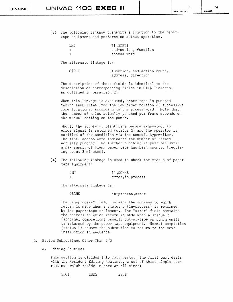
UP-4058 UNIVAC 1108 EXEC II SECTION:
(3) The following linkage transmits a function to the papertape equipment and performs an output operation.
LMJ + +
11 ,QOUT$ end-action, function access-word
The alternate linkage is:
Q$OUT function, end-action count, address, direction
The description of these fields is identical to the description of corresponding fields in QIN$ linkages, as outlined in paragraph 2.
When this linkage is executed, paper-tape is punched taking each frame from the low-order portion of successive core locations, according to the access word. Note that the number of holes actually punched per frame depends on the manual setting on the punch.
Should the supply of blank tape become exhausted, an error signal is returned (status=2) and the operator is notified of the condition via the console typewriter. The final access word indicates the number of frames actually punched. No further punching is possible until a new supply of blank paper tape has been mounted (requiring about 3 minutes).
(4) The following linkage is used to check the status of paper tape equipment:
LMJ 11,QCHK$ + error,in-process
The alternate linkage is:
Q$CHK in-process,error
The "in-process" field contains the address to which return is made when a status 0 (in-process) is returned by the paper-tape equipment. The "error" field contains the address to which return is made when a status 2 (abnormal completion; usually out-of-tape on punch unit) is returned by the paper tape equipment. Normal completion (status 1) causes the subroutine to return to the next instruction in sequence.
2. System Subroutines Other Than I/O
a. Editing Routines
This section is divided into four parts. The first part deals with the Resident Editing Routines, a set of three simple subroutines which reside in core at all times:
EBO$ EBD$ EBF$
4 74 PAGE:

UP-4058 UNIVAC 1108 EXEC II SECTION:
Part 2 of this section describes two specialized editing routines included in the system library to edit the time and data:
ETOD$ EDATE$
Part 3 of this section describes the library package called the Generalized Output Editing Routine:
EOUT$
4
Part 4 of this section is a discussion of FORTRAN FORMAT specifications. This discussion, taken from the FORTRAN IV Programmer's Guide, is included in this manual to clarify references to FORTRAN formats. The EOUT$ routine, described in this section, and the X$FRMT routine described in Section 4 B.3.d., require a knowledge of FORTRAN format specifications for most efficient use.
(1) Resident Editing Routines
The Resident Editing Routines are used by the EXEC II system for construction of typewriter and printer messages produced by the system. They may be freely called by worker programs without interferring with the system. They may be used in end-action routines and symbionts as well as in normal coding.
(a) The following linkage is used to form (in a specified part of core) the fieldata representation of n octal digits in the low-order part of register A¢:
LMJ FF
11 ,EBC$ n,m,address
(in which: FF FORM 6,12,18)
The "n" field indicates the number of fieldata characters to be formed. The "m" field indicates which character in the core location "address" is to contain the least significant character formed (each character is 6 bits; "m" takes values of 0-5 to indicate character positions from left to right in the word). Characters are loaded sequentially from the least significant (in position "m" of "address") to the most significant (using sequentially lower core locations, if necessary.). Leading zeros are not suppressed.
The above linkage may be generated by the procedure call:
E$BO col,image,count
This procedure will generate proper value of "m" and "address" to form "count" characters ("count"="n") with the least significant character in column "col" of the core area beginning at location "image". The leftmost character of "image" is considered column 1 • Column numbers may be as large as desired.
75 PAGE:

UP-4058 UNIVAC 1108 EXEC II SECTION:
(b) The following linkage is used to form the fieldata representation of the decimal value of the contents of register A0:
LMJ FF
11 ,EBD$ n,m,address
Refer to the explanations given for the EBO$ linkage for interpretation of the "FF" line. Leading zeros will be suppressed, and the resulting field will be prefixed by a "-" if A0 is negative.
A procedure call similar to that described for EBO$ is included in the system library:
E$BO col,image,count
The explanations given for the procedure call E$BO are true for E$BD.
(c) The following linkage is used to store the "n" fieldata characters in the low order part of A0:
LMJ FF
11 ,EBF$ n,m,count
The fields "n", "m" and "count" are identical to corresponding fields in the linkage to EBO$, ex~ept
that in this case "n" may contain any value up to 63. If "n" is greater than 6, the characters will be repeated cyclically a sufficient number of times to satisfy "n". Note that character transfer begins with the least significant character.
The following procedure call may be used to generate the above linkage:
E$BF col,image,count
Refer to the explanation given for the procedure E$BO for interpretation of the above proGedure.
(2) Clock Editing Routine
One of the interrupt features controlled by EXEC II (see Section 3 A.3.) is the real-time clock, register Rp. This register decrements by 1 every millisecond with an interrupt generated whenever it attempts to decrement through zero. The real-time clock is used by EXEC II to maintain a cell called MTOD$'which is updated once per second: the format of MTOD$ ]s:
4
bits 35 29 28 24 23 18 17 0
MTOO$I r-------y-e-a-r---~~I~---M-on-th------~------O-ay-----~I~----------------T-im-e--------------~I
76 PAGE:

UP-40S8 UNIVAC 1108 EXEC II SECTION:
The "year" field contains the binary representation of. the last two digits of the current calendar year; the "month" field contain the binary representation of the current month, from 1 to 12; the "day" field contains the binary representation of the current date from 1 to 31; the "time" field contains the binary representation of the current time, in seconds from midnight.
(a) Two library subroutines are provided to edit MTOD$. The first is used to edit the "time" field and is called by the linkage:
LMJ FF
11 ,ETOD$ ¢,m,address
The fields "m" and "address" have the same meaning as the linkage to EBO$ (see part 1 of this section). Eight Fieldata characters are formed by ETOD$ representing the hours (hh), minutes (mm) and seconds (ss) of the current time on a 24 hour clock:
hh:mm:ss
A procedure call is available to generate the above linkage:
E$TOD col,image
The fields "col" and "image" have the same meaning as for the E$BO procedure (see part 1 of this section).
(b) The second subroutine associated with MTOD$ is used to edit the "year", "month" and "day" fields. It is called by the following linkage:
LMJ FF
11,EDATE$ ,0,m,address
The fields "m" and "address" have the same meanings as the linkage to EBO$ (see part 1 of this section). Nine Fieldata characters are formed (the third and seventh are blank):
dd xxx yy'
The fields "dd" and "yy" represent the day of the month (1 to 31) and the last two digits of the year, respectively. The field "xxx" contains a 3 letter alphabetic abbreviation of the month.,
A procedure call is available to generate the above linkage:
E$DATE col,image
The fields "col" and "image" have the same meaning as for the E$BO procedure (see part 1 of this section).
4 77 PAGE:

UP-40S8
F
UNIVAC 1108 EXEC II SECTION:
(3) Generalized Output Editing Routine: EOUT$
(a) Specifications and Function Listing
T
The generalized output editing routine is an interpretive routine in the standard library which will perform editing functions for output produced on the line printer, the card punch, and the typewriter. The interpretive instructions performed by the routine are constructed along with much the same lines as are machine language instructions:
18 17 16 15
o M
(F) - Function Code
(T) - Type Wheel, etc.
(D) - Decimal Point Location, etc.
(x) - Specifies indirect address and use of the simulated index register
(M) - Address (storage location of data, etc.)
o
The available functions are listed below with their function codes in octal and the name of the corresponding procedure call. Each procedure call generates a single function code in interpretive instruction format (see above).
The following is a listing of all functions included in this routine. Function codes are given in octal notation.
Editing Functions (Paragraph b)
E$D 01 - Decimal E$O 02 - Octal E$B 03 - Binary E$C 04 - Alphanumeric Characters E$A 05 - Alphanumeric Words E$E 06 - Floating-Point (FORTRAN E) E$F 07 - Floating To Fixed (FORTRAN F)
Output Functions (Paragraph c)
E$WT 10 - Write and Terminate E$W 11 - Write E$WS 12 - Write and Save
4 78 PAGE:

UP-40S8 UNIVAC 1108 EXEC II
Modal Functions (Paragraph d)
E$SCL 13 - Set Scale E$PNT 14 - Set Point E$FLD 15 - Set Field E$INDX 16 - Set Index E$OVRP 17 - Overpunch
Control Functions (Paragraph
E$TERM 20 - Terminate E$LINK 21 - Link E$JUMP 22 - Jump E$RPT 23 - Repeat E$CLR 24 - Clear
SECTION:
e)
The routine is called by the following instructions:
LMJ 11,EOUT$
There are two entry points to this subroutine. The normal entry point is EOUT$. The other, EOUTR$, is the point for re-entry after E$TERM (Terminate) function and is discussed under Terminate.
The addressed word in the M designator may be either in control register or core storage. Any word, even a volatile register, is permissible; but if register 11 is addressed, the location of the interpretive word which references 11 will be put out. All registers, including volatile ones, are saved and restored. The X designator is used to specify indirect addressing and the use of the single simulated index register. Its permissible values are
o No action
Use address indirectly
2 Apply simulated index register
3 Apply simulated index register then use address indirectly
Indirect addressing is permitted to one level only, and the b,h, and i designators of the indirectly addressed word are ignored. However, it is possible to indirectly address film storage. All modes may be used with indirect addressing.
The various functions are described in detail below. They are all callable as procedures. Each of the procedure calls will generate one word in the proper format. The parameters of these procedures are interpreted differently depending on the number written. A single parameter is taken as M; two parameters as M and X; three parameters as T, D, and M; and four as T, D, M, and X. Any missing parameters will be assumed to be zero.
4 79 PAGE:
UP-4058 UNIVAC 110B EXEC II SECTION:
Entry to the generalized editor may be obtained by the procedures E$OUT or E$OUTR, depending on the entry point desired. No parameters are required.
(b) Editing Functions
These functions actually convert the information to be put out. In all cases except E$A, Alphanumeric Words (see E$A below) the T field specifies the type wheel at which the right-most digit, bit, or character is to print.
E$D - Decimal: The address word is treated as if it were a signed decimal integer and is edited without a decimal point unless a Set Point (14) is in effect. Leading zeros to the left are suppressed and a minus sign, if any, is printed immediately to the left of the number (also see Overpunch (17)). If the value is zero, a single zero will print. If a Set Point is in effect, the decimal number is assumed to have the stated point specified by the Set Point, and the D field specifies the number of decimal digits to be printed to the right of the decimal point. If a Set Field (15) with D=O is in effect, the specified field is treated as an unsigned decimal integer.
E$O - Octal: The D low-order bits of the addressed word are edited and printed as (D+2)/3 octal digits, unsigned. For a full octal, binary, or alphanu~eric character word, D must always be given as 36.
E$B - Binary: The D low-order bits of the addressed word are edited as D binary digits unsigned.
E$C - Alphanumeric Characters: The D low-order bits of the addressed word are edited and printed as (D+5)/6 alphanumeric characters in Fieldata code.
E$A - Alphanumeric Words: The D words beginning with the addressed word are edited as 6*D characters in Fieldata code. For this editing function only, the T field specifies the print position at which the left-most character is printed.
E$E - Floating-Point (FORTRAN E): The addressed word is edited as a floating-point number with D significant digits. Normally these will all print to the right of the decimal point (also see Set Scale). A decimal exponent consisting of a sign and two digits will be inserted immediately to the right of the significant portion. If the floating-point number is negative, a minus sign will be inserted immediately to the left of the number (also see Overpunch). If the addressed word is minus zero, no effect will occur, and the field will be left blank.
E$F - Floating to Fixed (FORTRAN F): The addressed word is assumed to be a floating-point number and is edited to fixed-point with D places following the decimal point. Negative numbers, including minus zero, are treated as above.
4 80 PAGE:
UP-4058 UNIVAC 1108 EXEC II SECTION:
(c) Output Functions
The output functions serve to transmit. the edited line to an output device; the printer, the card punch, or the typewriter. The device to be used is determined by the D field:
Printer D=O
Card Punch D=1
Typewriter D=2
The word or character count is given in the T field. This count must be given. (It is not assumed maximum if it is given as zero.) For the printer, the word count is normally 22; for the card punch, normally 14. For the typewriter, T is a character count and cannot be more than 60. For the printer, the M designator serves to specify the number of lines to be spaced. A value greater than the lengeth of a logical page will result in printing on the first line of the next page. For the punch and typewriter, the M designator is ignored.
E$WT - Write and Terminate: The edited image is transmitted to the specified device, and the routine returns to the next instruction in machine language mode. The image is reset to blanks.
E$W - Write: The edited image is transmitted to the specified device, and the routine continues in the interpretive mode. The image is reset to blanks.
E$WS - Write and Save: The edited image is transmitted to the specified device, and the routine continues to the next instruction in the interpretive mode. The image is left available for use by further output functions or further editing.
(d) Modal Functions
The modal functions serve to enter information which affects the interpretation of one or more of the instructions which follow. Five modal instructions are available.
E$SCL - Set Scale: The contents of the address field are treated as a signed power of 10 to be applied to any Floating-Point or Floating to Fixed function which follows the Set Scale. For Floating-Point, the scale is the number of digits to be printed to the left of the decimal point. The exponent field is reduced accordingly, so that the resulting value is the same as if no Set Scale modal were in effect. Negative values of the address (the 16 bit ones' complement) will introduce leading zeros after the decimal point and increase the exponent field accordingly.
4 81 PAGE:
UP-4058 UNIVAC 1108 EXEC II SECTION:
For Floating To Fixed conversion, the actual value of the resulting number is altered by multiplying it by the power of 10 indicated by the address. The Set Scale modal remains in effect until it is countermanded by a new Set Scale. Upon initial entry to EOUT$, the scale is assumed to be O.
E$PNT - Set Point: The Set Point modal specifies the position of the binary point for the next editing function to be encountered (presumably a Decimal editing function). It remains in effect only for the single edit. The address of the set point gives the number of bits following the binary point. Negative values are permitted (See Set Field).
E$FLD - Set Field: The Set Field modal is used to specify a subfield of the next word to occur (presumably a Decimal, Octal, Binary, or Alphanumeric Characters function). The T field specifies the left-hand margin and the M field the right-hand margin. The bits of the machine word are numbered, for the purposes of this function, from left (00) to right (35). The D field specifies extension of sign; if it is non-zero, the field is treated as signed. A Set Field with D=O and T=O may be used to treat fields, including the sign bit, as unsigned unless M=35 (i.e., a whole word must always be signed in the event a sign is applied).
The Set Field modal remains in effect only for the next function encountered. If both a Set Field modal and a Set Point modal are in effect when editing occurs, the Set Field modal will be applied first. In this case, the Set Point specifies the binary point counting from the right-hand end of the specified field.
E$NDX - Set Index: The Set Index is used to address a quantity in storage which is to be loaded into the single simulated index register. For any function which addresses storage (including this one), the presence of a 1 bit in the increment (H) portion of the address will cause the simulated index to be added to the specified address before access is made. The left half of the index-register word is ignored. If the D field is nonzero, the contents of the M field (with sign extension) are loaded into the simulated index register. The Set Index modal remains in effect until it is countermanded by another Set Index.
E$OVRP - Overpunch: The Overpunch modal specifies that any minus signs produced by the editing functions are to be removed from their positions in front of the edited numbers and placed as 11-punches over the loworder digits. In the case of Floating Point editing, the sign of the mantissa is placed over the low-order digit of the mantissa and the sign of the exponent over its low-order digit. The space that would normally contain the sign of the exponent is omitted.
4 82 PAGE:
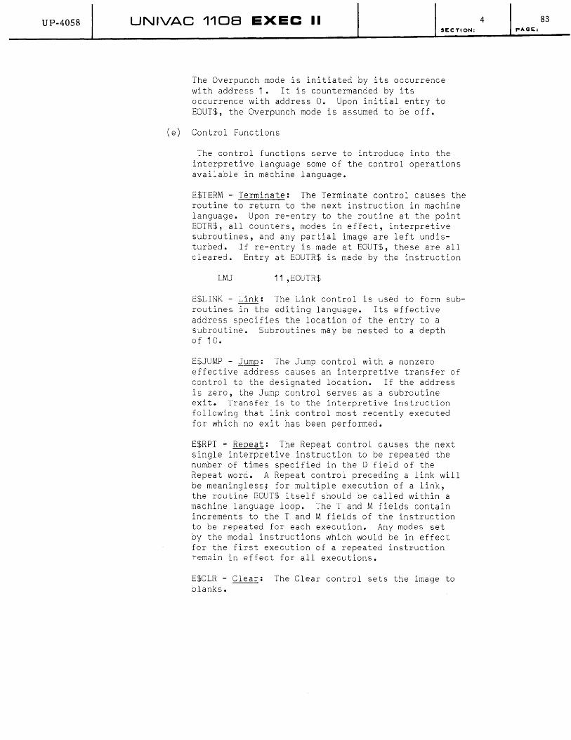
UP-40S8 UNIVAC 1108 EXEC II SECTION:
The Overpunch mode is initiated by its occurrence with address 1. It is countermanded by its occurrence with address o. Upon initial entry to EOUT$, the Overpunch mode is assumed to be off.
(e) Control Functions
The control functions serve to introduce into the interpretive language some of the control operations available in machine language.
E$TERM - Terminate: The Terminate control causes the routine to return to the next instruction in machine language. Upon re-entry to the routine at the point EOTR$, all counters, modes in effect, interpretive subroutines, and any partial image are left undisturbed. If re-entry is made at EOUT$, these are all cleared. Entry at EOUTR$ is made by the instruction
LMJ 11 ,EOUTR$
E$LINK - Link: The Link control is used to form subroutines in the editing language. Its effective address specifies the location of the entry to a subroutine. Subroutines may be nested to a depth of 10.
E$JUMP - lump: The Jump control with a nonzero effective address causes an interpretive transfer of control to the designated location. If the address is zero, the Jump control serves as a subroutine exit. Transfer is to the interpretive instruction following that link control most recently executed for which no exit has been performed.
E$RPT - Repeat: The Repeat control causes the next single interpretive instruction to be repeated the number of times specified in the D field of the Repeat word. A Repeat control preceding a link will be meaningless; for multiple execution of a link, the routine EOUT$ itself should be called within a machine language loop. The T and M fields contain increments to the T and M fields of the instruction to be repeated for each execution. Any modes set by the modal instructions which would be in effect for the first execution of a repeated instruction remain in effect for all executions.
E$CLR - Clear: The Clear control sets the image to blanks.
4 83 PAGE:

UP-40S8 UNIVAC 1108 EXEC II
(f) Examples*
Several examples of typical calling sequences to EOUT$ follow:
Example 1. The FORTRAN instruction
PR INT 1 00, A, I, N, B, C
100 FORMAT (6X, E20 .7, I2¢, 02¢, 1P2F2¢.6)
is equivalent to the interpretive sequence
E$OUT
E$E 26,7,A
E$D 46,¢,I
E$O 66,¢,N
E$CL
E$F 86,6,B
E$F 1¢6,6,C
E$WT 22,0,1
Next machine language instruction
SECTION:
Example 2. If this line were to be put out also on the card punch, whose output code is 1 , then the last interpretive instruction would be replaced by
E$NS 14,1 , ° E$WT 22,0,1
Only the first 80 columns of the image would be punched.
4
* The use of FORTRAN formats here is merely to indicate the format desired. The I/O functions in FORTRAN employ an editing scheme peculiar to themselves.
84 PAGE:
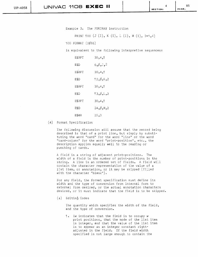
UP-40S8 UNIVAC 1108 EXEC II 4
(4)
SECTION:
Example 3. The FORTRAN instruction
PRINT 100 (J (I), K (I), L (I), M (1),1=1,4)
100 FORMAT (2,016)
is equivalent to the following interpretive sequences:
E$RPT 30,4,1
E$D 6,,0,J ,2
E$RPT 30,4,1
E$D 12,0,K,2
E$RPT 30,4,1
E$D 13,,0,L,2
E$RPT 30,4,1
E$D 24,,0,M,2
E$WR 22,0
Format Specification
The following discussion will assume that the record being described is that of a print line, but simply by substituting the word "card" for the word "line" or the word "card-column" for the word "print-position", etc., the description applies equally well to the reading or punching of cards.
A field is a string of adjacent print-positions. The width of a field is the number of print-positions in the string. A line is an ordered set of fields. A field will contain the character representation of the value of a list item, or annotation, or it may be skipped (filled with the character "blank").
For any field, the format specification must define its width and the type of conversion from internal form to external form desired, or the actual annotation characters desired, or it must indicate that the field is to be skipped.
(a) Editing Codes
The quantity which specifies the width of the field, and the type of conversion.
1. Iw indicates that the field is to occupy w print positions, that the mode of the list item is integer, and that the value of the list item is to appear as an integer constant rightadjusted in the field. If the field width specified is not large enough to contain the
85 PAGE:

UP-40S8 UNIVAC 110B EXEC II SECTION:
entire integer, only the least significant portion of the integer will appear in the field. In this case, the sign is the first character to be lost. If the field width specified is larger than that required for the constant it will be filled out to the left with blanks.
2. Fw.d indicates that the field is to occupy w print positions, that the mode of the list item is real, and that the value of the list item is to appear as a floating-point constant (without exponent) right-adjusted in the field with a decimal-point character occupying the d+1 st print position from the right-hand end of the field. D digits of the Fractional part of the number are printed to the right of the decimal point. As much of the integer part of the number as there is, or as much as the field width permits, whichever is the smaller, prints to the left of the decimal point. If the number is negative, and the field width permits, then a minus sign is printed immediately to the left of the most significant digit of the number. If the field width specified is larger than that necessary to contain the number, it is filled out to the left with blanks.
3. Ew.d indicates that the field is to occupy w print positions, that the mode of the list item is real, and that the value of the list item is to appear as a decimal number right-adjusted in the field in the form
±¢.xxx ••• E±ee
in which xxx ••• x are the d most significant digits of the mantissa, and ee is the corresponding two digit exponent. If the exponent is positive, a blank will follow the E. If it is negative, a minus sign will follow E.
The minimum field width necessary to contain a number of this type, including the sign of the fraction is 7+d. If the width specified is less than 7+d, then characters are successively lost from the left. If the field width specified is larger than that necessary to contain the number, it is filled out to the left with blanks.
4. Ow indicates that field is to occupy w print positions, that the value of the list item is to be interpreted as a 12 digit octal number, and that the quantity is to be printed as an octal number, right-adjusted in the field. If the field width is less than or equal to 12, then the w least significant digits will appear. If the field width is larger than 12, then it will be filled out to the left with blanks. Leading zeros will be printed if the field width allows.
4 86 PAGE:

UP-4058 UNIVAC 1108 EXEC II SECTION:
5. Aw indicates that the field is to occupy w print positions. It assumes that the list item is to be interpreted as a variable containing six alphanumeric characters. If w is less than or equal to 6, the left-most w characters of list item are placed in the field. If w is greater than 6, then the six characters of the list item are placed in the field, right-adjusted, and the field is filled out with blanks.
6. wX indicates that a field, w in length, is to be filled with blanks (on output) or ignored (on input). This field designation is independent of the list items.
7. wH indicates that the field is to occupy w print positions. The field is interpreted as annotation, and is to be filled with the w characters (including blanks) which follow the H. This field designation is independent of the list items.
(b) Specifications of a Line Format
The specifications of a line format are simply a string of editing codes separated by commas. (The comma following specifications of the form wH or wX is optional.). The line format specification positions the fields, in the order of their appearance in the string, in the following manner:
Sl occupies Print Positions 1 through Wi' inclusive.
S2 occupies Print Positions Wi + 1 through Wi + w2 ' inclusive.
Sn occupies Print Positions T through T + Wn, inclusive, in which Si is the itn editing code in the string of n editing codes; Wi is the field width of Si; and
n-1 T= 1 + L wk
k=1
(c) Editing Code Repetition
Whenever, in the specification of a line format, two or more successive editing codes (except for wH and wX) are identical in every respect, a shorthand notation may be used. This is accomplished by writing the editing code only once and prefixing it with an unsigned integer constant n indicating the desired number of repetitions of the field.
4 87 PAGE:
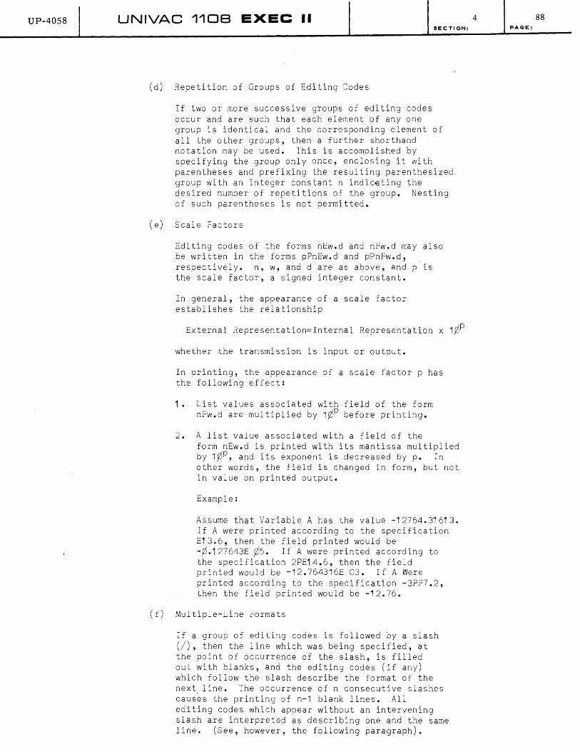
UP-4058 UNIVAC 1108 EXEC II
(d) Repetition of Groups of Editing Codes
If two or more successive groups of editing codes occur and are such that each element of anyone
SECTION:
group is identical and the corresponding element of all the other groups, then a further shorthand notation may be used. This is accomplished by specifying the group only once, enclosing it with parentheses and prefixing the resulting parenthesized group with an integer constant n indic€ting the desired number of repetitions of the group. Nesting of such parentheses is not permitted.
(e) Scale Factors
Editing codes of the forms nEw.d and nFw.d may also be written in the forms pPnEw.d and pPnFw.d, respectively. n, w, and d are as above, and p is the scale factor, a signed integer constant.
In general, the appearance of a scale factor establishes the relationship
External Representation=Internal Representation x 1¢P
whether the transmission is input or output.
In printing, the appearance of a scale factor p has the following effect:
1. List values associated with field of the form nFw.d are multiplied by 1¢P before printing.
2. A list value associated with a field of the form nEw.d is printed with its mantissa multiplied by 1¢P, and its exponent is decreased by p. In other words, the field is changed in form, but not in value on printed output.
Example:
Assume that Variable A has the value -12764.31613. If A were printed according to the specification E13.6, then the field printed would be -¢.127643E ¢5. If A were printed according to the specification 2PE14.6, then the field printed would be -12.764316E 03. If A Were printed according to the specification -3PF7.2, then the field printed would be -12.76.
(f) Multiple-Line Formats
If a group of editing codes is followed by a slash (/), then the line which was being specified, at the point of occurrence of the slash, is filled out with blanks, and the editing codes (if any) which follow the slash describe the format of the next, line. The occurrence of n consecutive slashes causes the printing of n-1 blank lines. All editing codes which appear without an intervening slash are interpreted as describing one and the same line. (See, however, the following paragraph).
4 88 PAGE:

UP-40S8 UNIVAC 110B EXEC II SECTION:
(g) Relationship of a Format and an Input/Output List
During the execution of an I/O Statement, the format specification is scanned from left to right. Editing codes of the form sH and sX are interpreted and the corresponding fields generated without reference to the I/O List. When an editing code of any other form occurs, one of two situations will arise: either there is at least one list element remaining to be transmitted, or there is not. In the former case, the next list element is converted according to the specification and transmitted. The format scan then continues. In the latter case, the transmission is terminated.
If, during the course of the format scan, the end of the format is reached while there are list elements remaining to be transmitted, the scan is resumed with the character following the preceding open parentheses, or, if there is none, from the beginning of the format.
b. Control Routines Other Than Input/Output
Among the subroutines included in the EXEC II system are several which control the action of the executive. These resident routines permit worker programs a good deal of flexibility, since they modify the environment within which the program operates, or direct executive routines to perform actions specified by worker programs.
Two sets of control routines are described in the following paragraphs. The first set controls the action of the system when error interrupts occur. (The error interrupts are described in paragraph 1, below). This set includes the resident routines:
MSEA$ paragraph 2
MREA$ paragraph 3
The second set of control routines directs the LOAD routine (see Section 2 A.), which brings programs into core from drum. This set includes the resident routines:
MLOAD$ paragraph 4
MCHN$ paragraph 5
(1) Error Interrupts
EXEC II utilizes the hardware error interrupts generated by the 1108 to signal certain error conditions. Some modification of the interpretation by the software of the hardware interrupt has been necessary to maintain compatibility with the 1107. The following conditions are considered to be "error interrupts" under the EXEC II system (hardware interrupts not included in the following list are ignored):
(a) Illegal Function: occurs when a function code is executed which is not in the 1108 repertoire.
4 89 PAGE:
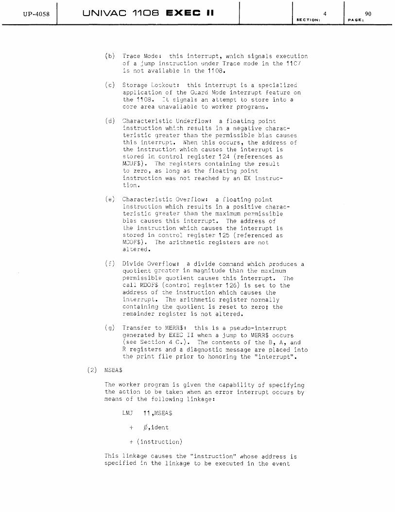
UP-40S8 UNIVAC 1108 EXEC II SECTION:
(b) Trace Mode~ this interrupt, wnich signals execution of a jump instruction under Trace mode in the 1107 is not available in the 1108.
(c) Storage Loskout: this interrupt is a specia:ized application of the Guard Mode interrupt feature on the 1108. It signals an attempt to store into a core area unavailable to worker programs.
(d) Characteristic Underflow: a floating point instruction wh::h results in a negative characteristic greater than the permissible bias causes this interrupt. When this occurs, the address of the instruction which causes the interrupt is stored in control register 124 (references as MCUF$). The registers containing the result to zero, as long as the floating point instruction was not reached by an EX instruction.
(e) Characteristic Overflow: a floating point instruction which results in a positive characteristic greater than the maximum permissible bias causes this interrupt. The address of the instruction which causes the interrupt is stored in control register 125 (referenced as MCOF$). The arithmetic registers are not altered.
(f) Divide Overflow: a divide com~and which produces a quotient greater in magnitude than the maximum permissible quotient causes this interrupt. The call MDOF$ (control register 126) is set to the address of the instruction which causes the interrupt. The arithmetic register normally containing the quotient is reset to zero; the remainder register is not altered.
(g) Transfer to MERR$: this is a pseudo-interrupt generated by EXEC II when a jump to MERR$ occurs (see Section 4 C.). The contents of the B, A, and
(2) MSEA$
R registers and a diagnostic message are placed into the print file prior to honoring the "interrupt".
The worker program is given the capability of specifying the action to be taken when an error interrupt occurs by means of the following linkage:
LMJ 11,MSEA$
+ y),ident
+ (instruction)
This linkage causes the "instruction" whose address is specified in the linkage to be executed in the event
4 90 PAGE:

UP-4058 UNIVAC 1108 EXEC II
of the error interrupt specified by "ident". "Ident" may have any of the following values:
MIFCT$ Illegal function
SECTION:
MITRC$ Trace Mode (not available in 1108)
MTLOK$ Storage Lockout
MICUF$ Characteristic Underflow
MICOF$ Characteristic Overflow
MIDOF$ Divide Overflow
MIERR$ J '-..lmp to MERR$
The above linkage may be generated by the procedure call:
M$SEA ident, (instruction)
Prior to executing the worker-program-specified instruction when a jump to MERR$ occurs, EXEC II resets to execute the standard system routine for all error interrupts when they next occur. Standard routines are described in the following paragraph. Note: Norker program use of the MERR$ "interrupt" is generally not recommended.
(3) MREA$
The worker program may reset to execute the standard error interrupt routine by the following linkage:
LMJ 11 ,MREA$
+ ¢, ident
The "ident" field is identical to the corresponding field for the MSEA$ linkage, described in paragraph 2, except that an additional value for "ident" is possible:
MIALL$ all error interrupts
The linkage to MREA$ may be generated by the procedure call:
M$REA ident
Standard action for the error interrupts available on the 1108 is as described under MSEA$, except that Illegal Function, Storage Lockout or Jump to MERR$ cause termination of the run via MERR$. Standard Handling of the MERR$ "interrupt" is described in Section 4 C ••
(4) MLOAD$
The LOAD routine (see Section 2 A.) may be called on in several ways. When a program is executed (by means of an XQT card; see Section 3 B.S.b.) a certain portion of core is committed to the worker program, and this is loaded with the segment to be executed first. Within this segment may be an area of core to be overlaid by
4 91 PAGE:

UP-40S8 UNIVAC 110B EXEC II SECTION:
another segment (the Allocator provides space for the largest such overlay when the program is allocated). Refer to Section 3 8.4.a. and 3 B.5.b. for a discussion of program structure.
When an overlay segment is to be given control, two meth8ds are available to do so. The first is called "automatic loading" since it involves no special linkages. When a jump is specified (except SLJ) in execution to an externally defined symbol (See Section 2 B.S.) of a seg~ent which uses an overlay area, the loader determines whether the segment is currently in core; if not, the required segment is loaded from drum. Once the segment is in core the required jump is completed. Note that the jump instruction performed by the worker program actually references LOAD; this is provided for by the Allocator. Registers, etc. are preserved by the loader during this action. Automatic loading is described under the SEG card of MAP (Section 38.5.a.).
The second method of specifying an overlay is called "manual loading", since it involves a special linkage. This differs from automatic loading 8nly in the fact that the segment called for will be loaded from drum whether or not it is already in core. The linkage used for manual loading is:
LMJ 11 ,MLOAD$
+ symbol ,segment
This loads the seg~ent whose name is in the "segment" field of the linkage, and ju~ps to the location specified by "symbol", where "symbol" is an externally defined symbol in the segment being loaded.
(5) MCHN$
Chained programs differ from overlays in the core commitment made. The Allocator allows core space for the largest overlay included in a segment, while it allocates only sufficient core for each individual link included in a chained program (except for "blank common"). Chained programs are discussed under the CHN card of MAP (see Section 38.5.a.).
Each link of a chained program must be individually called in by an explicit reference to the loader; any link may call any other link by using the following calling sequence, with the link number in A¢:
LMJ 11 ,MCHN$
Each link must be uniquely numbered on a CHN :ard in a MAP for thi s I inkage to 'Nork properl y, and the current link must release all r/o chan~els before the next link can be loaded.
4 92 PAGE:
UP-4058 UNIVAC 1108 EXEC II 4 SECTION:
3. Diagnostic Subroutines
a. General Information and Function Listing
b.
The EXEC II system provides a set of diagnostic subroutines designed to be incorporated into a worker program. These subroutines permit dynamic dumping to occur, and are therefore collectively called the "snap-shot" system. (See Section 3 B.9. for a description of non-dynamic diagnostic routines.) ~hen any of these subroutines is called, it performs some part of the dump routine required, while saving and restoring all control registers and the carry and overflow indicators. The general technique used in dumping is to write information on the Execution area on the drum, (see Section 2 B.4.) consisting of core, drum, control register or magnetic tape storage contents, using tables generated by the processors (see Section 3 B.4.) and the Allocator (see Section 3 B.5.).
The diagnostic subroutines are called by means of 14, 1108 Assembler Procedures, which are divided into 4 groupings, as follows:
(1 )
(2)
(3)
(4)
Conditionals: (4 B.3.b.)
X$AND X$IF X$OR X$TALY
Dump Procedures: (4 B.3.c.)
X$CORE X$DRUM X$DUMP X$FILM X$MESG X$TAPE
Specification Procedures: (4 B.3.d.)
Marking Procedures: (4 B.3.e.)
X$BACK X$MARK
X$BUFR X$FRMT
In addition to the "snap-shot" system, ICS (see Section 3 B.9.) may be called by a worker program by means of linkages to the following routines:
MILDR$
MIDMP$
These linkages are described in Section 4 B.3.f •• Note that these linkages are not dependent on the diagnostic information generated by the processors or the Allocator; also the drum is not used by ICS to store dumps as is done by "snapshot" system subroutines.
Conditional Procedures
X$AND paragraph 2
X$IF paragraph 1
X$OF paragraph 3
X$TALY paragraph 4
93 PAGE:
UP-40S8 UNfVAC 1108 EXEC II SECTION:
These procedures are used to specify whether a dump procedure is to be effective. They may precede or be interspersed with other snap-shot dump procedures, and their effeot, which is cumulative, is based on the setting of a system switch indicating a value of 'true' or 'false' for the current logical expression. This switch is set 'true' in the absence of conditional procedures and is dependent on conditionals when they are present. Dumping occurs only when the switch is set 'true'. Each conditional procedure described in the following paragraphs generates a three word calling sequence to a library subroutine.
(1) X$IF is the first conditional of a conditional string, and serves to execute a test which sets the condition switch to 'true' or 'false' accordingly. It is called by:
X$IF U1 ,X1 ,J1 'rel' U2 ,X2 ,J2
The fields are defined as follows:
U1,U2 core or control register addresses or literals
X1 ,X2 index regi ster designators
J1 ,J2 j-designators as used in the 1108 Assembler
'reI' a logical operator from the set:
'GT' Greater than
'LT' Less than
'EQ' Equal to
'NE' Not equal to
'LE' Less than or equal to
'GE' Greater than or equal to
Omitted fields are treated as zero. Indirect addressing (specified by an asterisk preceding or following either U-field) is permitted; index register incrementation, however is not provided for.
(2) X$AND procedure has the same format and function as the X$IF procedure, except that the condition switch is set 'true' if and only if it is already set 'true' and the current test is true. It is analogous to a logical "and" operator.
(3) X$OR procedure has the same format and function as the X$IF procedure, except that the condition switch is set 'false' if and only if it was already set 'false' and the current test is false. It is analogous to a logical "inclusive-or" operator.
(4) X$TALY procedure is used to set the conditional switch by testing a counter. The counter is set to zero the first time this procedure is executed and is incremented by 1
4 94 PAGE:
UP-4058 UNIVAC 110B EXEC II SECTION:
following all tests by the procedure, each time the procedure is entered in execution (except as noted below*). The call is as follows:
X$TALY start,until,every
The three fields contain numbers to be used in testing the counter; if omitted 'start' is assumed to be zero, 'until' is assumed to be 218 _1, and 'every' is assumed to be 1 • The tests performed on the counter (the symbol "Z" represents the counter) are as follows:
1 ) If 'start' .:;: Z < 'until' ,
and 2) If Z-'start' 'every'
has a zero remainder,
and 3) If the conditional switch is already set 'true' ,
then, the conditional switch will be set 'true' by the procedure; if any of the tests fail, the conditional switch is set 'false'.
(5) An example of the use of conditional procedures will indicate how the conditional switch is set. Note that if other procedures (described in the following sections) are interspersed with conditionals, they will be effective if and only if the conditional switch is set to 'true' ~1 the time they are entered and they will have no effect on the setting of the switch.
Assume that a program contains the variables X, Y, and Z, and the parameters (constants) A, Band C. Also assume that the following procedures are executed sequentially (with or without other procedures or instructions interspersed) and that they are part of a loop which will be executed 4000 times. We count the number of executions starting with 0 and ending with 3999.
1 ) X$IF X 'EQ'A
2) X$OR X 'LT'Z
3) X$AND Y 'GT'B
4) X$OR y 'NE'Z
5) X$OR A 'EQ' 90
6) X$OR A 'EQ' 'A'
7) X$TALY 0,4000,100
If X, Y, and Z have values of 78, 80 and 88 respectively, and A, B, and C have values of 'A' (Fieldata character), 180 and octal 040 respectively, then the conditional switch will have the following values on the indicated execution (after execution of the indicated procedure).
*Note: If the conditional switch is set to 'false' when the procedure is entered, the counter is not incremented.
4 95 PAGE:
UP-4058
c.
UNIVAC 110B EXEC II SECTION:
Execution Count: 0 99 100
Procedure 1 ) False False False False
2) True True True True
3) False False False False
4) True True True True
5) True True True True
6) True True True True
7) True False False True
These values are determined by the conditional procedures as described in preceding paragraphs.
Dump Procedures
X$CORE paragraph
X$DRUM paragraph 2
X$DUMP paragraph 3
X$FILM paragraph 4
X$MESG paragraph 6
X$TAPE paragraph 5
These procedures generate linkages to the subroutines which output the information comprising the required dumps. The subroutines called use the Execution area on drum to store the information dumped; upon program termination through MERR$ or MEXITS (see Section 4C.) this information is read back, edited and printed. Program termination by a transfer to MXXX$ (see Section 4 C.) will by-pass the editing of all dumps.
All dump procedures except X$MESG expand into a 3 word calling sequence. X$MESG expands into a 2 word calling sequence.
(1) X$CORE procedure calls for dumping of an area of core storage (provided that the conditional switch is set to 'true'). It is called by:
X$CORE start,length,format
The 'start' field indicates the address of the first core location to be dumped, and the 'length' field specifies the number of core locations to be dumped. The 'format' field indicates how the information dumped is to be edited; it normally contains a single letter, such as A, E, F, I, 0, enclosed in quotation marks. For a description of format specifications, see Section 4 B.3.d., the X$FRMT procedure.
4 96 PAGE:
UP-4058 UNIVAC 1108 EXEC II SECTION:
(2) X$DRUM procedure calls for dumping of an area of drum storage (provided that the conditional switch is set to 'true'). It is called by:
X$DRUM access,length,format
The 'access' field contains the address of a core location in which is stored the drum address of the first drum location to be dumped. The length field specifies the number of drum location to be dumped. The format field indicates how the information dumped is to be edited. For a description of format specifications see Section 4 B.3.d., the X$FRMT procedure,
The X$DRUM procedure requires that an area of core be available into which the drum block may be read. This area of core is provided by means of the X$BUFR procedure (see Section 4 B.3.d.). While a block of drum larger than the core area provided may be dumped, greater efficiency results from specifying a core area large enough to accommodate the entire block at one time. In the absence of this core area, no dumping will occur.
(3) X$DUMP procedure calls for dumping information which specifies the current state of the machine (provided the conditions switch is set to 'true'). Included in this information are the settings of the console selective jump switches. This procedure also permits dumping core and control registers. It is called by:
X$DUMP start,length,format,registers
The fields 'start', 'length' and 'format' are used identically to the corresponding fields in the X$CORE procedure (paragraph 1). The field 'registers' specifies which control registers are to be dumped; it contains any combination of the letters B, A, R enclosed in quotation marks ( or may be omitted if no registers are desired). Any illegal combination of characters in the 'registers' field results in dumping all 3 sets of registers. The edited listing produced as a result of this procedure will contain the special information on carry and overflow first, followed by register dumps (all of which are octal format), followed by the specified core dump.
(4) X$FILM calls for a dump of control registers (provided that the condition switch is set to 'true'.). It is called by:
X$FILM start,length,format
The field 'start' contains the address of the first control register to be dumped; 'length' indicates the number of registers to be dumped; and the 'format' field indicates how the dumped information is to be edited. For a description of format specifications, see Section 4 B.3.d., the X$FRMT procedure.
4 97 PAGE:
UP-40S8 UNIVAC 1108 EXEC II SECTION:
(5) X$TAPE procedure calls for a dump of a block of magnetic tape (provided that the condition switch is set to 'true'). The block to be dumped is that block just prior to the position of the tape unit when the procedure is entered. The call to this procedure is:
X$TAPE unit, format
The field 'unit' should contain a single alphabetic enclosed in quotation marks, corresponding to the logical label designation on an ASG card (see Section 3 B.1 .b.). The ~ormat' field indicates how the dumped information is TO be edited. For a description of format specifications, see Section 4 B.3.d., the X$FRMT procedure.
lhe X$TAPE procedure requires that an area of core be available into which the tape block may be read. This area of core is provided by means of the X$BUF~ procedure (see Section 4 B.3.d.). Should the tape block be longer than the core area provided, only that information which fits into the core area will be dumped. In the absence of a core area, no dumping will occur.
(6) X$MESG procedure calls for inclusion of a diagnostic message with the dump information (provided that the condi tional swi tch is set to 'true'). The message is provided by the user in the calling sequence and will appear in the edited listing after all dumps taken before it and preceding all dumps taken after it. The calling sequence is:
X$MESG length
'diagnostic message'
The field 'length' specifies the number of words in the message which follows; the field 'diagnostic message' consists of any alphanumeric string enclosed in quotation marks, and will be printed exactly as it is assembled. This procedure permits a programmer to identify the conditions which caused a given dump by a suitable diagnostic.
d. Specification Procedures
X$BUFR paragraph
X$FRIvlT paragraph 2
These procedures are used to provide specifications for dump procedures (see Section 3 B.3.c.). They cause definitions to be made available to the "snap-shot" system which are used by dump procedures. They generate 2 word calling sequences, and they are independent of the setting of the conditional switch.
(1) X$BUFR procedure defines an area of core as a buffer for use by the X$TAPE procedure or the X$DRUM procedure. The same buffer may be used for any number of tape and drum dumps; it must be provided, however, prior to executing
4 98 PAGE:

UP-4058 UNIVAC 1108 EXEC II SECTION:
any X$TAPE or X$DRUM call for which it is to be effective. This procedure is called by:
X$BUFR start,length
The field 'start' designates the address of the first core location in the buffer, and the field 'length' specifies the length of the buffer.
(2) X$FRMT procedure defines an editing format to be used for editing dumps. It must be executed prior to executing any dump for which it is to be effective. It is called by:
X$FRMT number ,name
editing string
The field 'number' specifies the number of words in the editing string which follows. The field 'name' contains a letter to become the name of the format, as it is named in dump procedure calls; it must be enclosed in quotation marks. The 'editing string' field consists of a format definition exactly like the FORTRAN Format statement. It must be enclosed in parentheses. Any format defined by X$FRMT is limited to 116 characters per line. Any format (including the standard formats described below) may be dynamically redefined, with the most recent definition being effective. A complete discussion of FORTRAN Format specifications is included in Section 4 B.2.. The standard formats which follow are known to the system without use of the X$FRMT procedure.
Format name Editing string
'F' (8 F 14.8) Fixed decimal
'E' (8 E 14.8) Floating decimal
, I ' (8 I 14) Integer
'A' (16A6) Alphanumeric
'0' (8014) Octal
e. Marking Procedures
X$MARK
X$BACK
These procedures are used to mark points in program execution between which dumps are saved, and subsequent to which they are deleted. This permits the programmer to include dump procedures in a program under checkout which he will only want to see in case a routine does not terminate normally. These marking procedures generate 1 word calling sequences and are independent of the conditional switch.
X$MARK is used to denote the point beyond which dumps will be deleted if a given later point in the program is reached.
4 99 PAGE:
UP-4058 UNIVAC 1108 EXEC II SECTION:
X$BACK is used to denote the point at which the set of dumps following the last X$MARK call may be detected. X$BACK must be preceded in execution by a call to X$MARK.
Thus, X$MARK and X$BACK behave much as a pair of parentheses surrounding portions of a program in which dumps are to be saved for editing only if termination occurs between them.
X$MARK and X$BACK pairs may be nested to a depth of five. The total number of occurances of X$MARK and X$BACK is unrestricted. The calling sequence for these procedures is:
X$MARK
X$BACK
f. Calls to lCS
rcs (described in Section 3 B.9.a.) may be used by a worker program by means of the calling sequences described in this section.
(1) To put res into operation, the following instruction should be executed:
J MlLDR$
This is equivalent to turning lCS on by means of an "lCS" or "XOT rcs" control card (see Section 3 B.9.a.). Note that return to the worker program is not automatic; if a return is desired, an rcs "JUMP" operation must be executed. rf provision is not made to return to the worker program by means of the "JUMP" operation, rcs will turn control over to the system routine Cel (see Section 2 B.1.) when it terminates.
(2) To utilize the "octal dump" routine in rcs, the following calling sequence should be executed:
SLJ MIDMP$
F registers,length,address
(in which: F 3,5,18).
The field 'registers' contains a number from 0-7 corresponding to the "R" field of the rcs "snapshot" card (see table in Section 3 B.9.a.).
The field 'address' specifies the address of the first core location to be dumped; the field 'length' indicates the number of core locations to be dumped.
When this calling sequence is executed, the required areas of control and core storage are immediately printed. The execution area on drum is not needed, nor are any of the diagnostic tables produced by the processors or the Allocator.
4 100 PAGE:

UP-4058 UNIVAC 1108 EXEC II SECTION:
C. INITIALIZATION AND TERMINATION
A worker program is initialized by the user through the use of the XQT control card (see Section 3 B.S.b. and Appendix C). This results
4
in the construction and loading of the worker program and associated tables followed by a jump to the starting addfess of the worker program.
Control can be returned to the executive system by a jump to the system location MEXIT$, indicating normal completion of the worker program. The executive will continue executing the run as directed by the remaining control cards. A PMD control card with an 'E' option (refer to Section 3 B.9.b. and Appendixes C 1. and C 2.) will be bypassed. If non-control card or EOF control cards are encountered before reaching the next control card, these cards will be bypassed with a notation on the print output to the effect that such cards were encountered. Any dynamic dumps will be recalled from drum, edited and output into the print file (see Section 3 B.9.). ~hen using a processor, the user should refer to the processor manual to determine the method of indicating the return of control in the source language.
Return of control via a jump to the system location MERR$ indicates to the executive that the worker program is terminating in the error mode. The system responds by acting in the same manner as if control were returned via MEXIT$, except that; a) the contents of the B, A, and R registers are edited and entered into the print file, b) all noncontrol cards and EOF cards are ignored until a PMD, RUN, or FIN control card is encountered, and c) a PMD control card with or without the 'E' option will be honored. The remainder of the card deck following the PMD control will be processed as if the worker program terminated via MEXIT$.
When a return is made to MERR$, the reason for error termination is indicated by a message in the print file preceding the dump of the B, A and R registers. These diagnostic messages are explained in Section 6.
A jump to the executive return point MXXX$ will immediately terminate the run. All control cards and data cards will be ignored until a RUN or a FIN control card is encountered. Dynamic dumps will not be edited, and post-mortem dumps will not be honored. The message "RUN ABORTED" in the print file indicates termination via MXXX$.
The operator has the ability to cause a program to exit to either MERR$ or MXXX$. For the procedure of operator intervention refer to the 1108 EXEC II Operator's Reference Manual.
101 PAGE:
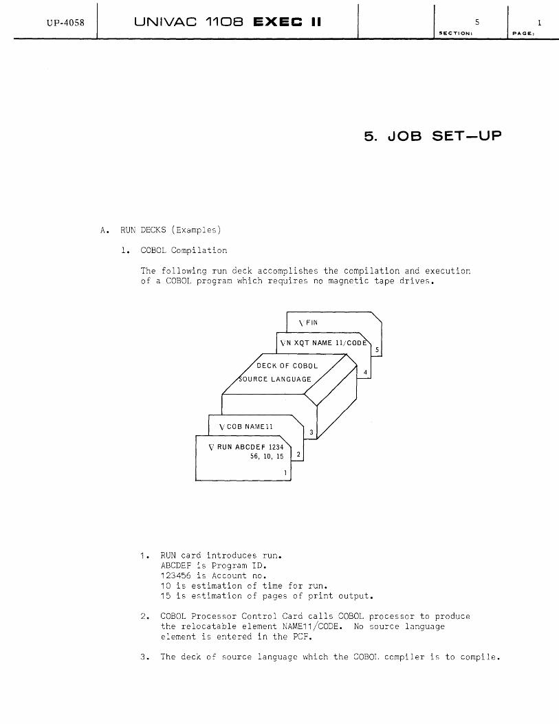
UP-4058 UNIVAC 1108 EXEC II 5 SECTION:
5. JOB SET-UP
A. RUN DECKS (Examples)
1. COBOL Compilation
The following run deck accomplishes the compilation and execution of a COBOL program which requires no magnetic tape drives.
V COB NAME 11
V RUN ABCDEF 1234 56, la, 15 2
1. RUN card introduces run. ABCDEF is Program ID. 123456 is Account no. 10 is estimation of time for run.
4
15 is estimation of pages of print output.
2. COBOL Processor Control Card calls COBOL processor to produce the relocatable element NAME11/CODE. No source language element is entered in the peF.
3. The deck of source language which the COBOL compiler is to compile.
1 PAGE:
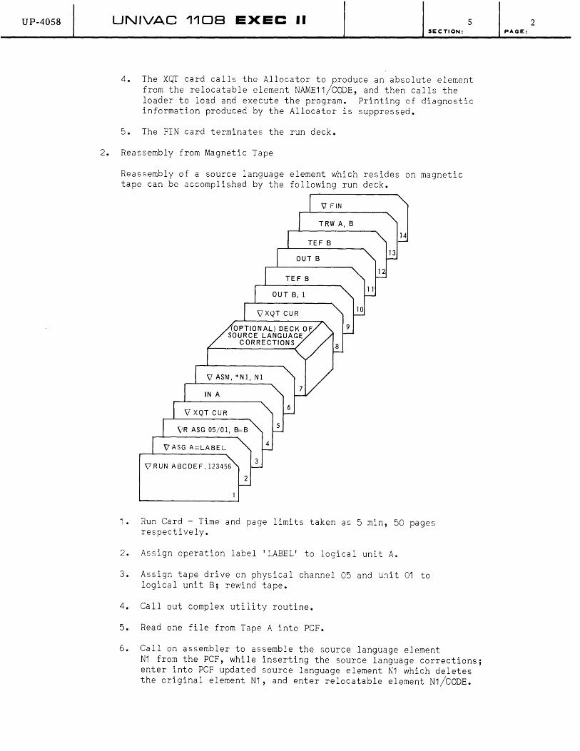
UP-4058 UNIVAC 1108 EXEC II 5 SECTION:
4. The XQT card calls the Allocator to produce an absolute element from the relocatable element NAME11/CODE, and then calls the loader to load and execute the program. Printing of diagnostic information produced by the Allocator is suppressed.
5. The FIN card terminates the run deck.
2. Reassembly from Magnetic Tape
Reassembly of a source language element which resides on magnetic tape can be accomplished by the following run deck.
\l FIN
TRW A, B
14 TEF B
13
12 TEF B
au T B, 1
9
6
vR ASG 05/01, B=B 5
4
\7RUN ABCDEF, 123456 3
2
1. Run Card - Time and page limits taken as 5 min, 50 pages respectively.
2. Assign operation label 'LABEL' to logical unit A.
3. Assign tape drive on physical channel 05 and unit 01 to logical unit B; rewind tape.
4. Callout complex utility routine.
5. Read one file from Tape A into PCF.
6. CalIon assembler to assemble the source language element N1 from the PCF, while inserting the source language corrections; enter into PCF updated source language element N1 which deletes the original element N1, and enter relocatable element N1/CODE.
2 PAGE:
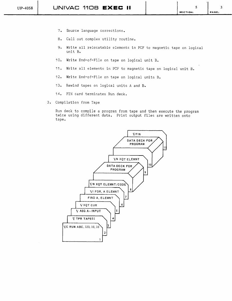
UP-4058 UNIVAC 1108 EXEC II 5 SECTION:
7. Source language corrections.
8. Callout complex utility routine.
9. Write all relocatable elements in peF to magnetic tape on logical unit B.
10. Write End-of-File on tape on logical unit B.
11 • Write all elements in PCF to magnetic tape on logical unit B.
12. Write End-of-File on tape on logical units B.
13. Rewind tapes on logical units A and B.
14. FIN card terminates Run deck.
3. Compilation from Tape
Run deck to compile a program from tape and then execute the program twice using different data. Print output files are written onto tape.
V ASG A= INPUT
VTPR TAPE01
VC RUN ABC, 123,10,10
3 PAGE:

UP-4058 UNIVAC 110B EXEC II 5
SECTION:
1. Run card-priority of 'ct.
2. TPR card directs print output to tape.
3. Assign logical unit 'A' to operational label 'Input'.
4. Call upon complex utility routine.
5. Position tape 'A' to beginning of the element 'ELEMNT'.
6. Call upon the FORTRAN Compiler to compile the element 'ELEMNT' from tape 'A'. The relocatable element 'ELEMNT/CODE' is produced.
7. Call the Allocator to allocate the relocatable element 'ELEMNT/CODE', and then call the loader to load the program for execution.
8. Deck of data for use by the program 'ELEMNT/CODE'.
9. Same as 7. By selection rules, 'XQT ELEMNT' in this case.
1 o. Same as 8.
11. FIN card terminates deck.
4. CUR Run To List Table of Contents For PCF Stored on Magnetic Tape
11
8
6
VRUN AB, 12, 10,20,7,8 3
2
4 PAGE:

UP-40S8 UNIVAC 1108 EXEC II SECTION:
1. Run card-lAB' is the ID, 12 is the account no. estimated time 10 min, estimates pages 20 pages, print output to channel 7, punch output to channel 8.
2. Assign operational label 'NAME' to logical unit 'X'.
3. Callout the complex utility routine.
4. Read 1 file from tape X into PCF.
5. Print listing of table of contents of rCF.
6. Position tape X to beginning of third file.
7. Era se PCF.
8. Read 3rd file from tape X into PCF.
9. Print listing of elements in peF.
10. Rewind tape X with interlock.
11. FIN card terminates run deck.
5 5 PAGE:
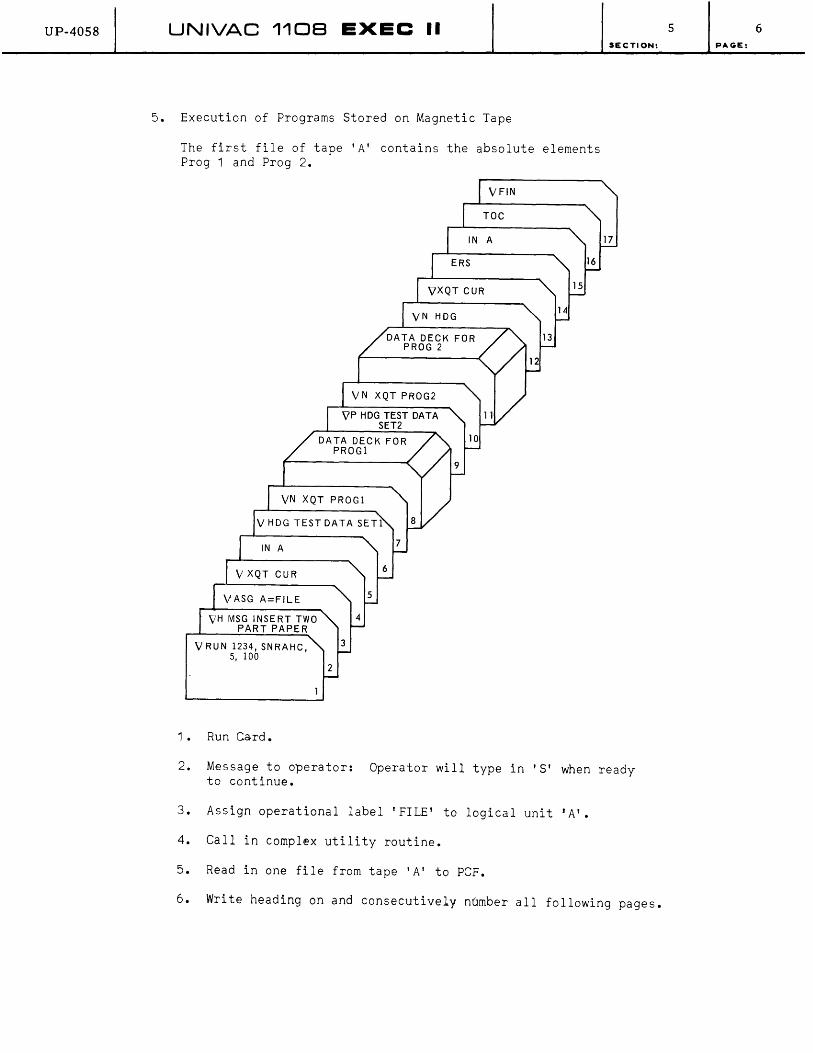
UP-40S8 UNIVAC 1108 EXEC II
5. Execution of Programs Stored on Magnetic Tape
The first file of tape 'A' contains the absolute elements Prog 1 and Prog 2.
VH MSG INSERT TWO PART PAPER
V RUN 1234, SNRAHC, 5, 100
1. Run Card.
DATA DECK FOR PROGI
7
6
2
VFIN
TOC
15
13
12
SECTION:
17
2. Message to operator: Operator will type in'S' when ready to continue.
3. Assign operational label 'FILE' to logical unit 'A'.
4. Call in complex utility routine.
5. Read in one file from tape 'A' to PCF.
6. Write heading on and consecutively number all following pages.
5 6 PAGE:
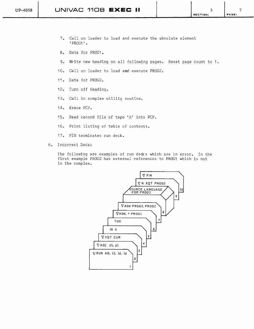
UP-4058 UNIVAC 110B EXEC II SECTION:
7. CalIon loader to load and execute the absolute element 'PROG1' •
8. Data for PROG1.
5
9. Write new heading on all following pages. Reset page count to 1.
10. CalIon loader to load and execute PROG2.
11. Data for PROG2.
12. Turn off Heading.
13. Call in complex utility routine.
14. Erase PCF.
15. Read second file of tape IAI into PCF.
16. Print listing of table of contents.
17. FIN terminates run deck.
6. Incorrect Decks
The following are examples of run deds which are in error. In the first example PROG2 has external references to PROG1 which is not in the complex.
VRUN AS, 12,111',111'
2
7 PAGE:

UP-4058 UNIVAC 1108 EXEC II SEC TION:
1. Run card.
2. Improper assign card-ignored.
3. Calion complex utility routine.
4. No operation performed because 'A' is not defined.
5. List (empty) table of contents.
6. Assembly not possible because source language PROG1 is not in complex.
7. Calion assembler to assemble source language element PROG2.
8. Source language for assembler.
9. Program execution not possible since PROG1 not in complex.
10. FIN card terminates run deck.
In this example an incorrect RUN card invalidates the deck.
V RUN $12,iA
1. Incorrect form of RUN card.
2. These cards ignored.
3. FIN card terminates deck.
B. REMOTE OPERATION
5
The remote user essentially has full use of EXEC II. characterisitics of remote operation are noted here. can be found in the 1108 Operator's Reference Manual.
However, certain Further information
8 PAGE:
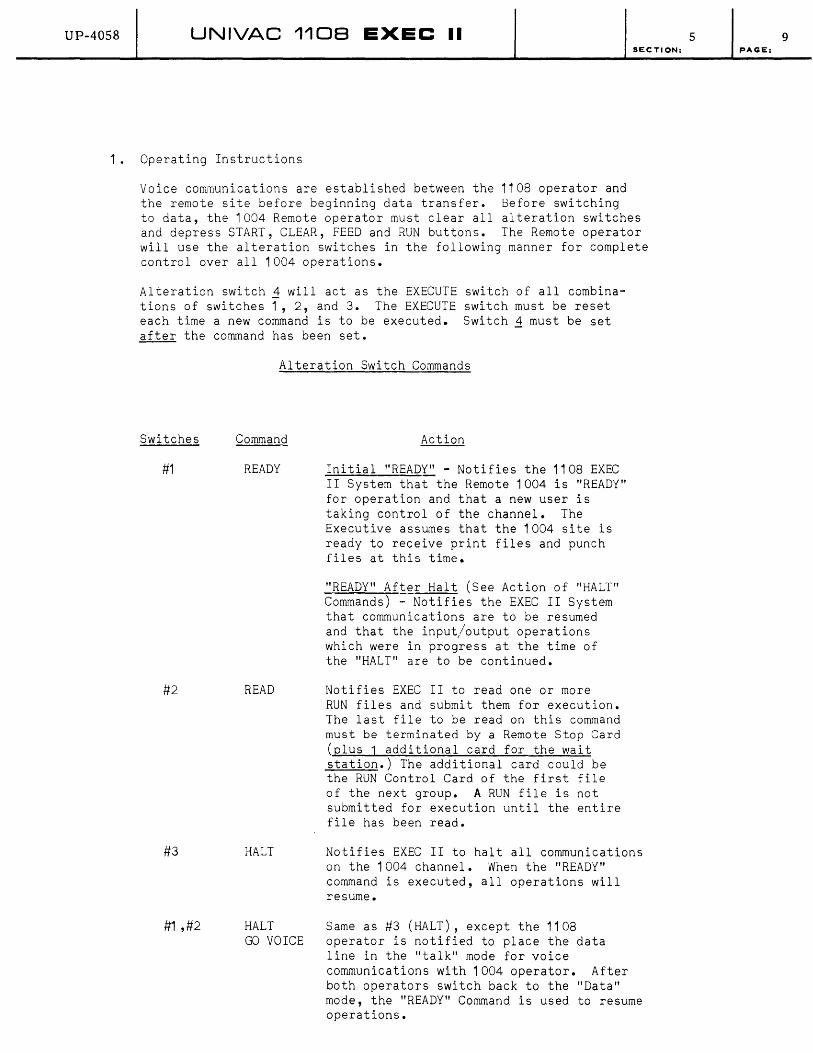
UP-4058 UNIVAC 1108 EXEC II SECTION:
1. Operating Instructions
Voice communications are established between the 1108 operator and the remote site before beginning data transfer. Before switching to data, the 1004 Remote operator must clear all alteration switches and depress START, CLEAR, FEED and RUN buttons. The Remote operator will use the alteration switches in the following manner for complete control over all 1004 operations.
Alteration switch 1 will act as the EXECUTE switch of all combinations of switches 1, 2, and 3. The EXECUTE switch must be reset each time a new command is to be executed. Switch 1 must be set after the command has been set.
Switches
#1
#2
#3
#1 ,#2
Alteration Switch Commands
Command
READY
READ
HALT
HALT GO VOICE
Action
Initial "READY" - Notifies the 1108 EXEC II System that the Remote 1004 is "READY" for operation and that a new user is taking control of the channel. The Executive assumes that the 1004 site is ready to receive print files and punch files at this time.
"READY" After Halt (See Action of "HALT" Commands) - Notifies the EXEC II System that communications are to be resumed and that the input/output operations which were in progress at the time of the "HALT" are to be continued.
Notifies EXEC II to read one or more RUN files and submit them for execution. The last file to be read on this command must be terminated by a Remote Stop Card (plus 1 additional card for the wait station.) The additional card could be the RUN Control Card of the first file of the next group. A RUN file is not submitted for execution until the entire file has been read.
Notifies EXEC II to halt all communications on the 1004 channel. When the "READY" command is executed, all operations will resume.
Same as #3 (HALT), except the 1108 operator is notified to place the data line in the "talk" mode for voice communications with 1004 operator. After both operators switch back to the "Data" mode, the "READY" Command is used to resume operations.
5 9 PAGE:
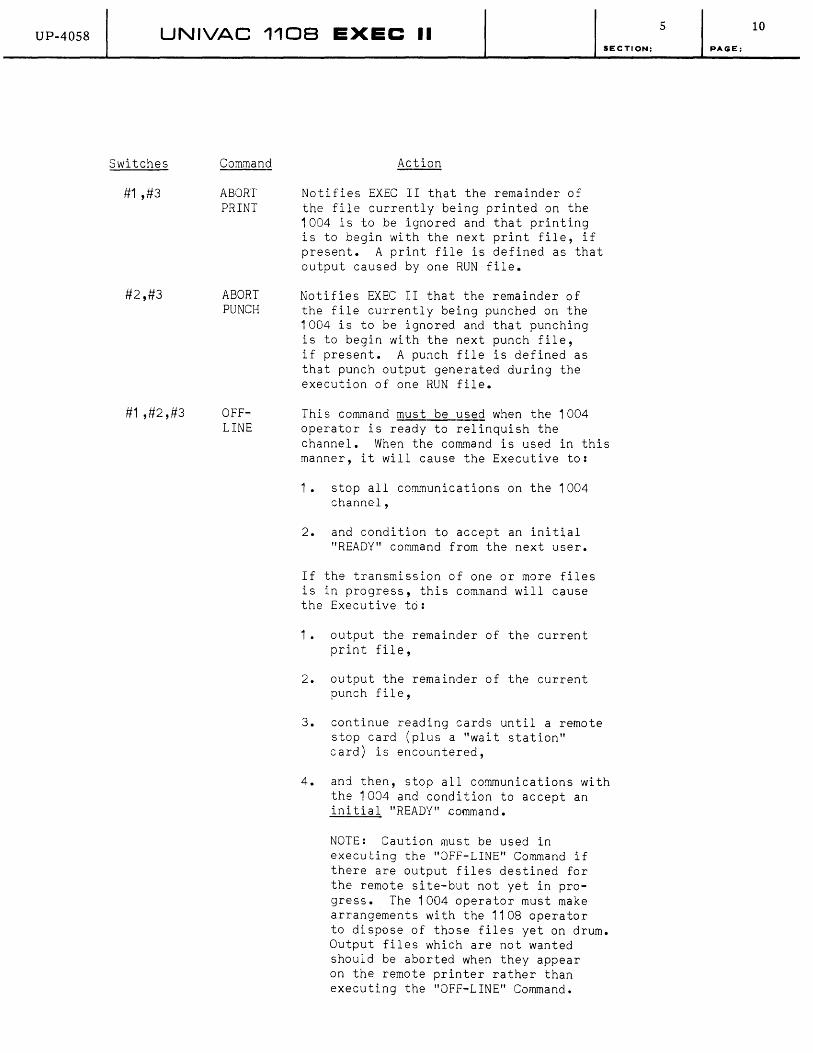
UP-40S8 UNIVAC 1108 EXEC II
Switches
#1 ,#3
#2,#3
#1 ,#2,#3
Command
ABORT PRINT
ABORT PUNCH
OFFLINE
Action
Notifies EXEC II that the remainder of the file currently being printed on the 1004 is to be ignored and that printing is to begin with the next print file, if present. A print file is defined as that output caused by one RUN file.
Notifies EXEC II that the remainder of the file currently being punched on the 1004 is to be ignored and that punching is to begin with the next punch file, if present. A pu~ch file is defined as that punch output generated during the execution of one RUN file.
SECTION:
This command must be used when the 1004 operator is ready to relinquish the channel. When the command is used in this manner, it will cause the Executive to:
1. stop all communications on the 1004 channel,
2. and condition to accept an initial "READY" command from the next user.
If the transmission of one or more files is in progress, this com~anj will cause the Executive to:
1. output the remainder of the current print file,
2. output the remainder of the current punch file,
3. continue reading cards until a remote stop card (plus a "wait station" card) is encountered,
4. and then, stop all communications with the 1004 and condition to accept an initial "READY" command.
NOTE; Caution must be used in executing the "OFF-LINE" Command if there are output files destined for the remote site-but not yet in progress. The 1004 operator must make arrangements with the 1108 operator to dispose of those files yet on drum. Output files which are not wanted should be aborted when they appear on the remote printer rather than executing the "OFF-LINE" Command.
5 10
PAGE:
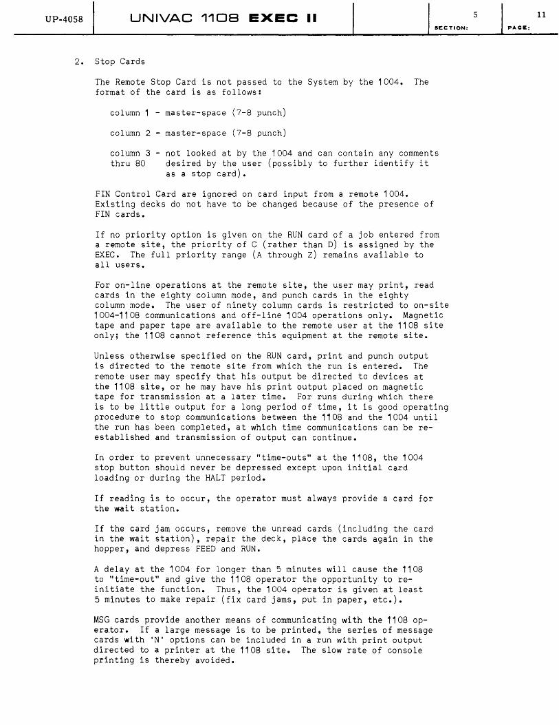
UP-4058 UNIVAC 1108 EXEC II SECTION:
2. Stop Cards
The Remote Stop Card is not passed to the System by the 1004. The format of the card is as follows:
column 1 - master-space (7-8 punch)
column 2 - master-space (7-8 punch)
column 3 - not looked at by the 1004 and can contain any comments thru 80 desired by the user (possibly to further identify it
as a stop card).
FIN Control Card are ignored on card input from a remote 1004. Existing decks do not have to be changed because of the presence of FIN cards.
If no priority option is given on the RUN card of a job entered from a remote site, the priority of C (rather than D) is assigned by the EXEC. The full priority range (A through Z) remains available to all users.
For on-line operations at the remote site, the user may print, read cards in the eighty column mode, and punch cards in the eighty column mode. The user of ninety column cards is restricted to on-site 1004-1108 communications and off-line 1004 operations only. Magnetic tape and paper tape are available to the remote user at the 1108 site only; the 1108 cannot reference this equipment at the remote site.
Unless otherwise specified on the RUN card, print and punch output is directed to the remote site from which the run is entered. The remote user may specify that his output be directed to devices at the 1108 site, or he may have his print output placed on magnetic tape for transmission at a later time. For runs during which there is to be little output for a long period of time, it is good operating procedure to stop communications between the 1108 and the 1004 until the run has been completed, at which time communications can be reestablished and transmission of output can continue.
In order to prevent unnecessary "time-outs" at the 1108, the 1004 stop button should never be depressed except upon initial card loading or during the HALT period.
If reading is to occur, the operator must always provide a card for the wait station.
If the card jam occurs, remove the unread cards (including the card in the wait station), repair the deck, place the cards again in the hopper, and depress FEED and RUN.
A delay at the 1004 for longer than 5 minutes will cause the 1108 to "time-out" and give the 1108 operator the opportunity to reinitiate the function. Thus, the 1004 operator is given at least 5 minutes to make repair. (fix card jams, put in paper, etc.).
MSG cards provide another means of communicating with the 1108 operator. If a large message is to be printed, the series of message cards with 'N' options can be included in a run with print output directed to a printer at the 1108 site. The slow rate of console printing is thereby avoided.
5 11
PAGE:
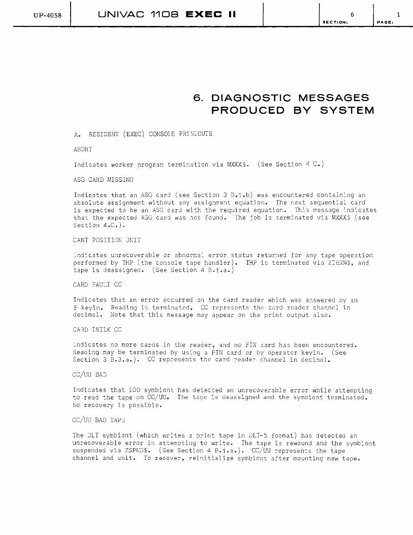
UP-40S8 UNIVAC 1108 EXEC II 6 SECTION:
6. DIAGNOSTIC MESSAGES PRODUCED BY SYSTEM
A. RESIDENT (EXEC) CONSOLE PRINTOUTS
ABORT
Indicates worker program termination via MXXX$. (See Section 4 C.)
ASG CARD MISSING
Indicates that an ASG card (see Section 3 B.1.b) was encountered containing an absolute assignment without any assignment equation. The next sequential card is expected to be an ASG card with the required equation. This message indicates that the expected ASG card was not found. The job is terminated via MXXX$ (see Section 4.C.).
CANT POSITION UNIT
Indicates unrecoverable or abnormal error status returned for any tape operation performed by THP (the console tape handler). THP is terminated via ZTERM$, and tap e i s d e ass i g n ed • ( See Sec t ion 4 B. 1 • a • )
CARD FAULT CC
Indicates that an error occurred on the card reader which was answered by an F keyin. Reading is terminated. CC represents the card reader channel in decimal. Note that this message may appear on the print output also.
CARD INTLK CC
Indicates no more cards in the reader, and no FIN card has been encountered. Reading may be terminated by using a FIN card or by operator keyin. (See Section 3 B.3.a.). CC represents the card reader channel in decimal.
CC/UU BAD
Indicates that LOD symbiont has detected an unrecoverable error while attempting to read the tape on CC/UU. The tape is deassigned and the symbiont terminated. No recovery is possible.
CC/UU BAD TAPe:
The DLT symbiont (which writes a print tape in DLT-5 format) has detected an unrecoverable error in attempting to write. The tape is rewound and the symbiont suspended via ZSPND$. (See Section 4 B.1 .a.). CC/UU represents the tape channel and unit. To recover, reinitialize symbiont after mounting new tape.
1 PAGE:
UP-40S8 UNIVAC 1108 EXEC II 6 SECTION:
CC/UU BAD TAPE, RELEASED
The paper tape read symbiont has detected an unrecoverable tape error while attempting to write on magnetic tape. CC/UU represents the tape channel and unit. The tape is rewound and the symbiont suspended via ZSPND$ (see Section 4 B.1 .a.). To recover, reinitialize symbiont after mounting new tape.
CC/UU DEASSIGNED BY DMP
The DMP symbiont has inadvertently taken a file directory entry via ZNEXT$ (see Section 4 B.1.a.) for a file which is on tape. Since the entry which DMP deleted should have been available to another routine (e.g. PRINT$), the console operator must reinitialize the tape operation. Tape unit CC/UU is deassigned to permit this action.
CC/UU EMPTY
Indicates that the worker program has deassigned tape unit CC/UU, which was previously assigned to it. This may be done by the worker program calling THRU$. The unit is available for reassignment.
CC/UU EXHAUSTED
Indicates that the LOD symbiont has detected End-Reel on the file it was reading. The tape is rewound with interlock, and the symbiont is suspended via ZSPND$. The operator is expected to mount the next reel and reinitialize LOD.
CC/UU EXHAUSTED. MOUNT NEXT TAPE. INITIATE QPN
End-Reel sentinel was detected by the paper tape symbiont named QPN. The paper tape punch is turned off, the tape is rewound, interlocked, and QPN is suspended via ZSPND$. CC/UU represents the tape channel and unit. Operator action is obvious.
CC/UU FULL. MOUNT NEW TAPE AND INITIATE DLT
The DLT symbiont (which writes a print tape in DLT-5 format) has encountered the end of tape, and has no unit to swap to. The tape is rewound, interlocked, and the symbiont suspended via ZSPND$. Operator action is obvious. CC/UU represents the tape channel and unit.
CC/UU FULL. MOUNT NEW TAPE AND INITIATE QRN
Indicates End-of-File detected on the magnetic tape being read by the paper tape read symbiont named QRN. The tape has been rewound, interlocked, the paper tape reader has been turned off, and QRN is suspended. Operator action is obvious. CC/UU represents the tape channel and unit.
CC/UU FULL
Indicates that the DMP symbiont has encountered End-Reel on tape unit CC/UU. The tape is rewound with interlock, DMP is suspended via ZSPND$. The operator is expected to mount a new tape and reinitialize DMP.
CC/UU HAS NN FILES OF XXXXX
Indicates that the DMP symbiont has satisfied the operator keyin by du~ping (decimal number) NN files on tape unit CC/UU. XXXXX will be PRINT, PUNCH, INPUT corresponding to the type of file written.
2 pAC;E:

UP-40S8 UNIVAC 1108 EXEC II 6 SECTION:
cc/uu INPUT DONE, RELEASED
The paper tape read symbiont has transferred the number of files indicated by previous keyin to magnetic tape. The tape is rewound with interlock, and the symbiont is terminated via ZTERM$. CC/UU represents the tape channel and unit.
cc/uu IS .DL
Indicates that the DLT symbiont (which writes a print tape in DLT-5 format) has swapped to an alternate unit. The message refers to the completed tape, which is rewound. CC/UU represents the tape channel and unit.
cc/uu IS .NN
Indicates that system file tape .NN has been deassigned. deassigned unit. This may occur by operator keyin, e.g. the file on CC/UU has meaningful information.
CC/UU MOUNT REEL NN OF XXXXXX
CC/UU represents that G SW .PR. Note that
Indicates worker program calIon TSWAP$. NN represents the required reel number of the input file named XXXXXX. No action is necessary if the proper tape is mounted and not interlocked.
CC/uu PRINTED RELEASED
Indicates that the print symbiont has finished printing information on the tape it was reading. The tape is rewound with interlock, and the symbiont is terminated via ZTERM$. CC/UU represents the channel and unit of the tape.
CC/UU PUNCH TAPE BAD, RELEASED
Indicates that an unrecoverable error has been detected on the tape being read by the paper tape punch symbiont. CC/UU represents the tape channel and unit.
CC/UU PUNCHED RELEASED
PAGE:
Indicates that the paper tape punch symbiont has finished punching the information on the tape it has been reading, and has rewound the tape, interlocked, and terminated. CC/UU represents the tape channel and unit. This probably indicates a hardware malfunction. The operator may attempt to recover by reinitializing the operation which LaD was performing. If this fails, call field engineer.
CC/UU RELEASED, DRUM ERR
Indicates that the LaD symbiont has encountered an unrecoverable error return from the drum r/o package. The tape which is in use by LaD is deassigned (CC/UU) and LaD is terminated via ZTERM$.
CC/UU TAPE BAD
Indicates that the print symbiont has encountered either an unrecoverable error or invalid format on the tape it has been printing. The message PRINTED RELEASED will follow.
CC/UU .NN DIDNT REWIND
Indicates error return from tape I/O package attempting to rewind system file .NN on unit CC/UU. Normally this will type out when the tape is being deassigned. No action is required.
3
UP-4058 UNIVAC 1108 EXEC II 6 SECTION: PAGE:
ee/uu .NN REMOVE
Indicates that the completed system file .NN on tape unit CC/IUU is being deassigned. The tape should be removed, unless it is to be used at this time. Note that this message normally occurs when tape swap of system file takes place.
CI CCC
This typeout follows termination of a remote run. It contains the number of cards ir. the input deck (cec), corresponding to the CARDS IN field of the accounting line in the print output listing.
co eee PG PPP
After termination of a remote run, this line indicates the card and print output of the run. eec represents the number of cards punched, and PPP represents the number of pages printed. Note that this information also appears on the accounting line in the print output listing.
CODE ERROR CC
Indicates a nonvalid punch on the first of three cards in the error stacker of the card reader. These cards have not yet been passeo into the system. CC represents the card reader channel in decimal. The operator must respond with either F ee to terminate reading, or e ce (after any corrective action) to proceed.
DRUM ERROR IN CLEAR
Indicates that the drum I/O package has not returned a normal status during attempt to clear the dru~ to zero after a manual tape bootstrap. The system enters a loop (REBOOT).
DRUM FAULT CC/UU
Drum I/O package has encountered unrecoverable error on the drum on CC/UU. The unrecove~able error return is taken to the worker program. The status word in octal format follows the message. Note that this message may appear on the print output listing.
DRUM FULL
Indicates that no drum buffers are available for print output. This means that the worker program will not regain control until a routine such as the print symbiont releases a drum buffer. This typeout is not provided in some systems.
END RUN HH: fv1Jvl: SS
Typed at termination of a run. HH:fv1f'v1:SS represents the termination time in hours, minutes, and seconds.
ERR
Indicates unrecoverable tape or drum error during bootstrap. ~o portion of the system has been dependably loaded. Proper action is to reboot (if several attempts fail, call the field engineer).
ERROR
Indicates worker program termination via IIIERR$. (See Section 4.C.).
4

UP-40S8 UNIVAC 1108 EXEC II 6 SECTION:
ET HH:1VU\J1:SS
This typeout follows a remote run to indicate total central computer time used by the run (HH:MM:SS) in hours, minutes, and seconds, corresponding to the ELAPSED TIME field on the accounting line of the print output listing.
EXEC II
Indicates successful completion of that part of the bootstrap routine which loads the system into core and drum. Note that the processors have not yet been written to drum. The operator may now turn on the Real-Time Clock and type in time (T HH/MM) and data (D MM/DD/YY).
FILE NOT CUR FORr~T
Bootstrap operation has encountered a malformed file while attempting to load the processors. No processors are loaded. System tape must be corrected.
F I LE-TABLE- FULL
Indicates that the console tape handler (THP) has attempted to place an entry in the file directory via ZFILE$ (see Section 4 B.1.a.), and found it full. The routine is terminated without completing the tape operation. The operator should reinitialize the tape operation later.
IDLE
Indicates that no worker program is currently operating, and no run deck is available on the drum. (Replaces old typeouts BEGIN IDLE and END IDLE.)
I/O DELAY CC
Indicates that a single input or output operation on channel CC has not been completed within a preset arbitrary time. The dispatcher routine checks for channel activity on all channels and continues looping until all channels are clear. Note that this may occur if operator fails to respond to certain I/O error typeouts (e.g. TAPE ERROR).
KEY ER
Indicates that an unsolicited keyin was made incorrectly. The keyin causing this typeout is ignored.
LABEL ERROR LLLLLL UNIT X(NO OR GO)
Indicates failure of the file label check routine in the label and item package (see Section 4 B.1 .b., part 6). LLLLLL is the file name actually read in from tape. X specifies the logical unit (as on an ASG card. (See Section 3 B.1 .b.) The operator is expected either to mount a new tape and type in NO, or to type in GO to proceed with the file as though the label check had passed.
LABEL IN USE
Indicates that the operator has attempted to assign a tape with an operational label which is already in use. The new assignment is ignored.
5 PAGE:

UP-40S8 UNIVAC 1108 EXEC II 6 SECTION:
LATER
Indicates an unsolicited keyin has been made which cannot be handled because a previous keyin is still being worked on. The keyin causing this typeout is ignored.
MAX PAGES
Indicates that the current job has produced more print output than specified on RUN card (see Section 3.B.1.a.). The job is permitted to proceed normally.
MAX TIME
Indicates that the estimate of running time for the current job, as specified on RUN card (see Section 3.B.1 .a.) has been exceeded. The job is permitted to proceed normally.
MOUNT *
Calls for operator assignment of a scratch tape, as specified on an ASG card. (See Section 3.B.1 .b.)
MOUNT NNNNNN
Calls for operator assignment of a tape with operational label NNNNNN, as specified on an ASG card (see Section 3.B.1 .b.).
l'vlOUNT .DL
Calls for operator assignment of a tape to be used for print output in DLT-5 format, as specified on a TPR card (see Section 3.B.3.b.).
MOUNT .PR
Calls for operator assignment of a tape to be used for print output in standard format, as specified on a TPR card (see Section 3.B.3.b.) or as specified by a previous keyin.
MSG
Indicates a MSG card in the RUN deck (see Section 3.B.2.). The information on the card is typed next. No action is required, unless a WAIT message follows.
NNN LOAD ERROR
Indicates other than normal status was returned by the drum I/O package following
PAGE:
an attempt to read the symbiont named NNN from drum via ZLOAD (see Section 4.B.1 .a.). No further action is taken by EXEC.
NN PROCESSORS
Indicates number of processors loaded by bootstrap routine is NN. (NN will not be greater than 10.) This typeout occurs only if console jump switch 1 is set prior to the bootstrap.
6
UP-4058 UNIVAC 110B EXEC II 6
SECTION:
NO NNN
Indicates that the symbiont named NNN, which has been called for (e.g. by keyin) does not exist in the system. No further action is taken by EXEC II.
NO .NN ASSIGNED
Indicates deassignment of the system file tape .NN on unit CC/UU. This may occur due to tape swapping. No action is necessary.
NOISE BLOCK CC/UU
Indicates that a tape block smaller than the noise constant was encountered by the tape I/O package. No action necessary.
NOISE IS ON CC/UU
Indicates a status of 44 returned while attempting to skip while erasing on IVC, VIC, VIIIC drives. Return to the worker program is made via the abnormal return point. However no further action is taken by EXEC II.
NSI SS ON CH NN
Indicates occurrence of an interrupt for which the system was not prepared. SS contains the top 4 bits of the status word in octal notation. NN specifies the channel in decimal notation. EXEC takes no further action.
PARITY ERROR CC
Indicates hardware parity failure in remote transmission on channel CC. Operator may respond with either R CC to try again, or F CC to fault the channel and terminate the remote operation.
PRINT INTLK CC
Indicates hardware interlock on printer on channel CC (normally due to no more paper). Operator should correct the interlock condition, and type in either C CC to continue printing with the next line, or R CC to restart printing at top of last printed page.
PROCESSOR AREA TOO SMALL
Bootstrap routine has run out of drum space while attempting to load processors. System tape must be corrected.
PROCESSOR NOT ABSOLUTE TYPE
Bootstrap routine has encountered a non-absolute element while attempting to load processors. System tape must be corrected.
PROCESSORS
Indicates successful completion of the drum operations required to write the processors to the drum following a manual tape bootstrap. Operator should type in date and time and turn on the Real-Time Clock, if he has not yet done so.
7
PAGE:

UP-40S8 UNIVAC 1108 EXEC II 6 SECTION:
PUNCH FAULT CC
Keyin of F CC by the operator. The punch file is aborted and the associated punch symbiont is terminated. Note that this message may also appear on the print output. CC represents the punch channel.
PUNCH INTLK CC
Indicates a hardware interlock on the card punch unit. CC represents the punch channel. The operator is expected to respond by typing in either R CC (after refilling the hopper of the punch with blank cards) to continue, or F CC to terminate punching.
P.T. PUNCH EMPTY
Indicates no paper in the paper tape punch unit when the worker program attempted to punch via the paper tape I/O package. Abnormal status is returned to the worker program. Operator action after reloading the punch depends on program specifications (normally run request instructions).
REAL-TIME CLOCK INTERROGATED AT HH:MM:SS
Indicates the current time (HH:MM:SS) in hours, minutes, and seconds. Occurs due to the call LMJ 11, CLOCK by the worker program. No action is required.
RESTART DMP LATER
Indicates that the Dj~P symbiont has caught up with the Card Read symbiont while dumping card input to tape. DMP suspends itself via ZSPND$, and should be reinitialized after the Card Read operation is complete.
RESTORE PAP~R TO STANDARD FORMS
Indicates that a call was made in the preceding run to PAPER$. This called for special forms to be mounted in the printer. The special forms in the printer may now be removed and standard paper used. Note that no indication will be given if the paper is not changed when printing occurs.
RUN
Indicates that a user job is beginning. The information on the RUN card of the input deck is typed on the following line. The start time for the run also appears in the form HH:NM:SS, meaning hours, minutes, and seconds.
SCAT DRUM ERROR
During attempt to read EXEC from drum to create system tape via XQT RSDNT (see Section 3 B.8.), an abnormal completion or unrecoverable error status was returned from the drum I/O package. The routine terminates via IVlfRR$.
SERVO IN USE
Indicates operator attempted to assign a tape servo which has already been assigned. The new assignment is ignored.
8 PAGE:

UP-4058 UNIVAC 110B EXEC II 6 SECTION:
TAPE ERROR CC/UU
Indicates a non-normal completion of a tape operation. This is followed by the status word in octal format. The operator is expected to type in R CC, C CC, or F CC to attempt recovery, continue with the next tape block, or declare a fault condition respectively. No return is made to the worker program until operator action resolves the error. CC/UU specifies the tape unit.
TAPE FAILED TO WRITE MONITOR
During attempt to write system tape via XQT RSDNT (see Section 3 B.8.); an abnormal completion or unrecoverable error status was returned from the tape I/O package. The routine terminates via MERR$.
TAPE FAULT CC/UU
Indicates that an unrecoverable error condition exists on tape unit CC/UU. This may occur by operator keyin (F CC). The unrecoverable error return is made to the worker program. This typeout is followed by the status word in octal format. Note that this may also occur on the print output listing.
TAPE INTLK CC/UU
Indicates either that the tape is physically interlocked, or that a write was attempted on a unit which was protected against write operations. The operator has the same options as for a tape error condition. CC/UU represents the tape channel and unit.
TAS-CONFUSED
Indicates that an operational tape label given to the tape assignment routine, TAS, begins with , but is not known to the system (e.g •• PR). This may occur by erroneous keyin or by incorrect specification on an ASG card (see Section 3 B.1.b.). The tape assignment routine terminates itself without making any assignment.
TOO MANY PROCESSORS
Indicates attempt to load more than 10 processors (1108 Assembler, etc.) during bootstrap operation. Bootstrap is not completed. System tape must be corrected.
UPCERR
Indicates UNPRINTED CONTROL-CARD ERROR. The RUN, TPR, DPR, and HDG control cards at the beginning of a run deck are not placed immediately into the output print file, since later control cards may affect them. This error indicates too many such cards, or such a card out of place in the deck. The job is terminated via MXXX$.
VERIFY ERROR CC
Indicates a hardware card-read error. The three cards in the error stacker have not been passed to the system, and the first of these is the card which caused the typeout. CC represents the card reader in decimal. Operator may terminate card reading (F CC), or may continue reading, after any corrective action (C CC).
9
PAGE:

UP-4058 UNIVAC 110B EXEC II 6 SECTION:
WAIT
Indicates that the system is in the wait mode. Worker program activity is stalled until the operator types in S to permit it to proceed. The wait mode may occur by worker program specification (H option on MSG card, see Section 3 B.2.), or by operator keyin (S ON prior to run).
XXXXXX NOT A PROCESSOR
Bootstrap routine has encountered an absolute element which is not a processor while attempting to load the processors. System tape must be corrected. .
-NNN A
Indicates that the remote symbiont named NNN has been activated. No action is required.
-NNN ACTIVE
Indicates that the console operator has attempted to initialize the symbiont named NNN when it was already active. No further action is taken by EXEC II.
-NNN B
PAGE:
Indicates that the remote card read symbiont named NNN has detected some malformation in the buffer transmitted from the remote unit. This probably indicates either transmission problems or a plugboard error. The symbiont is terminated via ZTERM$ (see Section 4 B.1.a.).
-NNN NOT ACTIVE
Indicates that the console operator has referenced the symbiont named NNN without initializing it. A symbiont must be initialized before it may be otherwise referenced.
-NNN S
Indicates that the symbiont named NNN has been suspended via ZSPND$. (See Section 4 B.1.a.). This may be accomplished by operatoi keyin. (.NNN S).
-NNN T
Indicates that the symbiont named NNN has terminated via ZTERM$. (See Section 4 B.1.a.). Any tape used by the symbiont has been deassigned.
+RMN A
Indicates that the remote control routine RMN is active. RMN corresponds to a channel containing a CTS unit. The identification for the remote site is printed after this message when the routine is first activated. No action is required.
+RMN A
Indicates that the remote 1004 operator has temporarily halted transmission. RMN represents the remote control routine associated with a specific channel. The remote operator is responsible for further action.
10
UP-4058 UNIVAC 1108 EXEC II 6 SECTION:
~RMN H, GO VOICE
Indicates that the remote 1004 operator has temporarily halted transmission. RMN represents the remote control routine associated with a specific channel. The console operator is expected to switch the data phone for the indicated CTS unit to talk.
Indicates that the remote 1004 operator has terminated transmission to the CTS unit with which remote control routine named RMN is associated. No action is required.
*FTO CC
Indicates that the remote control routine associated with channel CC has detected no activity on the channel for a period of 5 minutes, although the channel was then active. The operator may respond with R CC to permit another five minutes, or F CC to terminate the remote operation, or make no response (leaving responsibility with 1004 operator to take corrective action).
1 004 ERROR CC
Indicates more than 30 seconds elapsed since last function on active on-site 1004 channel CC. Operator may respond with R CC to resume with the next function, or F CC to declare a fault condition and suspend the corresponding symbiont. Note that interlock of hardware may cause this.
11 PAGE:

UP-40S8 UNIVAC 1108 EXEC II SECTION:
6.B. RESIDENT (EXEC) PRINTER MESSAGES
ABOVE CARD IN ERROR
Indicates that ICS has encountered a card with improper format (see Section 3.B.9.A). The worker program is terminated via MXXX$.
ABOVE CONTROL CARD IN ERROR - IG~ORED
Indicates that a card containing a MASTER-SPACE in column one (7/8 punch, octal 00) was encountered, but it does nQt have the correct format for any known control card. The card is bypassed, and the run continues normally.
ACCOUNT
Printed on the accounting line following each run. Followed by the information found in the 'ACCOUNT NAME' field of the RUN card (see Section 3. B.1.A).
ASG CARD MISS ING
Indicates that an ASG card (see Section 3. B.1.B) was encountered containing an absolute assignment without any assignment equation. The next sequential card
6
is expected to be an ASG card with the required equation. This message indicates that the expected ASG card was not found. The job is terminated via MXXX$ (see Section 4. C.).
CALL FOR LOAD OF SUBSEGl\1ENT IN LINK WITH NO SUBSEGl'vlENTS
Indicates that the worker program has referenced MLOAD$ (see Section 4. B.2.B) to load a subsegment. But MLOAD$ found no subsegment in the current link. An erroneous map may produ:e this error (see Section 3. B.5.A). The worker program is terminated via MERR$.
CALLING SEQUENCE ERROR FROM LLLLLL
"First line of a 3-line printout supplied by BCSER$ (see Section 4. B.1.b.(5)(h)4.) from which the Block Buffering package was called erroneously. Followed by printout "The location of file description table is ""
CARD FAULT CC
Indicates that an error occurred on the card reader which was answered by an 'F' keyin. Reading is terminated. ICC' represents the card reader channel in decimal. This message will be printed in case of MERR$ termination if it was the last 'FAULT' message in the run.
CARDS IN
Printed on the accounting line following each run. Followed by a count in decimal of the number of cards in the input run deck.
CARDS OUT
Printed on the accounting line following each run. Followed by a count in decimal of the number of cards punched during the run.
12 PAGE:
UP-40S8 UNIVAC 1108 EXEC II SECTION:
COMPLEX OVERFLOW
Indicates that an attempt has been made to call a processor when no space exits in the user PCF. The processor call is ignored by EXEC II, and the job proceeds normally.
DATA CARDS ENCOUNTERED BY SYSTEM - IGNORED
Indicates that CCI (see Section 3. B.), which expects to read a control card, has encountered one or more cards which are not control cards. This may occur as a result of errors associated with control cards (such as missing or mispunched control cards) or may be due to program termination prior to end of the data deck it is reading.
DATE
Appears on the heading of each print page when called for by use of HDG card (see Section 3. B.3.C.). It is followed by the current date in the form 'DDMMYY' (day, month, year).
DEVICE ERROR FROM LLLLLL
6
"First line of a 3-line printout supplied by BDVER$ (see Section 4. B.1.b.(5)(h)4.); specifies the absolute location of the call to the Block Buffering package in which the error originated. Followed by printout "The location of file description is."
DRUM FAULT CC/UU
Drum I/O package has encountered unrecoverable error on the drum on 'CC/UU'. The unrecoverable error return is taken to the worker program. The status word in octal format follows the message. Note that this message appears only if it is the last fault message in the run at MERR$ termination.
DUMP I/O ERROR
Indicates unrecoverable error return from drum I/O package when the system is attempting to write dump information to the drum. The worker program is terminated via MXXX$. (See Section 4. C).
ELAPSED TIME HH MM SS
Printed on the accounting line following each run. 'HH MM SS' represents the total central processor time used by the run in hours, minutes and seconds.
ELEMENT TABLE OVERFLOW
Indicates overflow of element table in user PCF (see Section 2. 8.5). of this table is determined by constants in CONFIG (see Section 2. A). worker program is terminated via MXXX$ (see Section 4. C).
ERROR DURING LOAD IN MLOAD$
The size The
Indicates other than normal status returned to load (see Section 2. A) while attempting to read program subsegment from drum to core. This may occur when either manual or auto loading is being used (see Sections 3. b.5.A, 4.8.2.8). The worker program is terminated via MERR$.
13 PAGE:
UP-4058 UNIVAC 1108 EXEC II 6 SECTION:
ERRS IN ELEMENT PRODUCED
Whenever a processor produces an element containing errors, in the absence of certain option letters (see Appendix C), the element is marked as an error, with the message printed following the processor output listing. The job proceeds normally.
FILE MODE ERROR
Third line of a 3-line printout supplied by BCSER$ (see Section 4 B.1.b.(5)(h)4.); specifies the type of error which occurred (see Section 4. B.1.b.(5)(f)3.) followed by worker program termination via MERR$.
IDENT
Printed on accounting line following each run. Followed by the contents of the 'IDENTIFICATION NAME' field of the RUN card (see Section 3. B.1.B).
ILLEGAL OPERATION LLLLLL
Indicates that an illegal-operation interrupt occured. The location containing the illegal instruction is printed as 'LLLLLL', and the illegal operation is printed as 'WWWWWWWWWWWW'.
IMPROPER DRUM RELEASE
Third line of a 3-line printout supplied by BCSER$ (see Section 4. B.1.b.(5)(h)4.); specifies the type of error which occurred (see Section 4. B.1.b.(5)(f)3.) followed by worker program termination via MERR$.
INPUT SOURCE ELEMENT MALFORMED
Indicates that the source element (to be input from drum) 3pecified in the source name field of a processor call control card (see Sections 3. B.4, 3. B.5) is of the proper type to be input to the processor, but does not contain a symbolic 'PIECE' (see Section 2. B.5). This may arise from destruction of the table of contents in the user PCF, or by hardware malfunction, or (rarely) by a shuffled source deck input via an ELT card (see Section 3. B.6). The processor call is ignored and the run proceeds normally.
INPUT SOURCE LANGUAGE ELEMENT AMBIGUOUSLY SPECIFIED
Indicates that more than one element in the user PCF (or none in the user PCR, and more than one in the library PCF) matches the specifications in the source name field of a processor call control card (see Sections 3. B.4, 3. B.5). The processor call is ignored and the run proceeds normally.
INPUT SOURCE LANGUAGE ELEMENT NOT AVAILABLE
Indicates that no element in the user PCF or the library PCF matches the specifications in the source name field of a processor call control card (see Sections 3. B.4, 3. B.5). The processor call is ignored and the run proceeds normally.
14 PAGE:

UP-4058 UNIVAC 1108 EXEC II 6 SECTION:
IRRECOVERABLE READ ERROR
Third line of a 3-line printout supplied by BDVER$ (see Section 4. B.1.b.(5)(h)4.); specifies the type of error which occurred. (See Section 4. B.1.b.(5)(f)2.) followed by worker program termination via MERR$.
IRRECOVERABLE WRITE ERROR
Third line of a 3-line printout supplied by BDVER$ (See Section 4. B.1.b.(5)(h)4.); specifies the type of error which occurred. (See Section 4. B.1.b.(5)(f)2.) followed by worker program termination via MERR$.
I/O ERR IN SYSTEM
Indicates other than normal return from the drum I/O package when a worker program or nonresident portion of EXEC II is being loaded from drum. This does not apply to symbionts. The current job is terminated via MXXX$.
LINES OF WWWWWW WWWWWW OMITTED
Indicates that ICS is not printing duplicates of the word with octal format 'WWWWWW WWWWWW'. (See Section 3. B.9.A). The dump operation proceeds normally.
MERR$ TERMINATION
Indicates worker program terminated via MERR$ (see Section 4. C.).
MLOAD$ FOUND NO ACTIVE LINK IN LINK TABLE
Indicates MLOAD$ (see Section 4. B.2.B) has been referenced with no active worker program link. May be caused by map errors (see Section 3. B.5.A), or by failure of EXEC II or one of the processors. The worker program is terminated via MERR$.
MLOAD$ TABLE EXCEEDED-DIAGNOSTICS TERMINATED
Indicates that more than 50 subsegments have been activated via MLOAD$ (see Section 4. B.2.B) in the current link in a worker program. Diagnostics are terminated for the remainder of the link. However the worker program proceeds normally.
NNNNNN- CALL ERR FROM LLLLLL
Indicates an incorrect calling sequence to routine 'NNNNNN'. Register 11 which normally contains the return point from the subroutine is printed as 'LLLLLL'.
NO ICS
A call was made to ICS in a system which does not have ICS. (See Section 3. B.9.A). The worker program is terminated via MXXX$.
NO PROGRAM EXECUTED - NO DUMP TAKEN
Indicates that a PMD card was encountered which did not follow worker execution of a worker program. The PMD card is ignored and the run continues normally.
15 PAGE:
UP-40S8 UNIVAC 1108 EXEC II 6 SECTION:
NOT IN ERROR MODE - NO DUMP TAKEN
Indicates that a PMD card (see Section 3. B.9) with an 'E' option letter was encountered following program termination via MEXIT$. No dump is taken and the run continues normally.
OPERATOR KILLED RUN AT LLLLLL
Indicates that the console operator forced MERR$ termination by typing in 'E'. The current location in the worker program at the time of termination is printed as 'LLLLLL'.
PAGE
Appears on the heading of each print page when called for by use of HDG card (see Section 3. B.3.C). It is followed by the page number in decimal format.
PAGES
Printed on the accounting line following each run. Followed by a count in decimal of the number of pages of print output by the run.
PREVIOUS ASSIGNMENT FOR X IGNORED
Indicates that an ASG card (see Section 3. B.1.B) was encountered with a reference to logical unit 'X', which was previously assigned. The old assignment is ignored and the new one is honored, and the job proceeds normally.
PUNCH FAULT CC
Indicates either a failure in the punch unit, or a previous keyin of 'NNN F' by the operator. The punch symbiont is terminated. Appears if worker program terminates at MERR$ and this was the last 'FAULT' message in the run.
REMAINING CONTROL CARDS IGNORED
Indicates worker program termination via MERR$ followed by a control card which was not a PMD card with 'E' option. The remainder of the run deck is ignored.
RUN ABORTED
Indicates worker program termination via MXXX$. (See Section 4. C.).
RUN CONTROL CARD MISSING -- DECK NOT ACCEPTED
Indicates that the first card of an input file was not a RUN card. The job is terminated via MXXX$ (see Section 4.C.). All cards are ignored until a RUN card is encountered.
SNAP SHOT
Precedes print output of an ICS snap-shot operation. (See Section 3. B.9.A).
16 PAGE:
UP-4058 UNIVAC 1108 EXEC II SECTION:
STORE ERROR AT AAAAAA OR BBBBBB
Indicates that a storage lockout interrupt has occurred. The instruction which caused the interrupt is at either location 'AAAAAA' or 'BBBBBB'.
SYSTEM IN INTERRUPT CODING FOR CHANNEL CC
Indicates that at the time of MERR$ termination, channel ICC' was in control, and interrupts were prevented. This implies that routine was in interrupt coding.
TAPE FAULT CC/UU
Indicates that an unrecoverable error condition exists on tape unit ICC/UU'. This may occur by operator keyin ('F CCI). The unrecoverable error return is made to the worker program. This message appears only if it was the last fault condition prior to a MERR$ termination.
THE LOCATION OF FILE DESCRIPTION TABLE IS
Second line of a 3-line printout supplied by BDVER$ or BCSER$ (see Section 4. B.1.b.(5)(h)4.); specifies the absolute location of the file description table associated with the error. Followed by one of the following:
FILE MODE ERROR IMPROPER DRUM RELEASE IRRECOVERABLE READ ERROR IRRECOVERABLE WRITE ERROR
UNEXPECTED RETURN TO SYSTEM
Indicates that a worker program returned control to EXEC II other than through MEXIT$, MERR$, or MXXX$. The worker program is considered to have terminated via MXXX$ (see Section 4. C).
6 17 PAGE:

UP-4058 UNIVAC 1108 EXEC II
6.C. C.U.R. PRINTER MESSAGES
ABSOLUTE
6 SECTION:
Identifies a type 2 element on a table of contents listing. May also be produced by TOC operation in describing entry points for block data.
AN ABSOLUTE ELEMENT CANNOT BE LISTED
A LIST card told CUR to list an element found to be a type 2 (absolute) element. CUR has no facility for this operation. Error may be due to improper tape positioning. CUR continues in normal mode.
A PROCESSED MAP ELEMENT CANNOT BE LISTED
A LIST card told CUR to list an element found to be a type 4 (processed MAP) element. CUR has no facility to do this. Error may be due to improper tape positioning: CUR continues in normal mode.
BANK 1 DEPENDENT
Caused by TOC card describing entry points for block data.
BANK 1 INDEPENDENT
Caused by TOC card describing entry points for block data.
BANK 2 DEPENDENT
Caused by TOC card describing entry points for block data.
BANK 2 INDEPENDENT
Caused by TOC card describing entry points for block data.
BLANK COMMON
Caused by TOC card describing entry points for block data.
BLOCK TABLE
Heading for TOC block table listing.
BLOCK TABLE EMPTY
A TOC card told CUR to list the block table in the PCF. It is empty due to an ERS card or reboot. CUR continues in normal mode.
18 PAGE:

UP-40S8 UNIVAC 1108 EXEC II 6 SECTION: PAGE:
BLOCK TABLE OVERFLOW
Indicates that the number of block data programs entered in the PCF exceeds the amount of space allotted (in CONFIG) for the block table, which describes these elements. CUR enters the error mode causing the job to be terminated via l~XX$ after all CUR directive cards have been logged. The number of block data programs in the PCF must be reduced.
COBOL LI BRARY
Identifies a type 6 element on a table of contents listing.
COBOL LIBRARY TABLE
Heading for TOC COBOL library table listing.
COBOL LIBRARY TABLE EMPTY
A TOC card told CUR to list the COBOL library table. CUR found the table empty (due to ERS card, etc.). CUR continues in normal mode.
COBOL LIBRARY TABLE OVERFLOW
Indicates that the number of COBOL library elements in the PCF exceeds the amount of space allotted in CONFIG for the COBOL library table which describes the elements. CUR enters the error mode causing the job to be terminated via J~XX$ after all CUR directive cards have been logged. Number of such elements in the PCF must be reduced.
COMPLEX TOO LARGE
Abnormal return from block buffer. Due to writing to end of drum. After typeout routine exits to MERR$ and an ABORT message follows.
COMPR. SY MBOLIC
Identifies a type 5 element on a table of contents listing.
CUR OPERATION PERFORMED
CUR is in error mode, logging directives. This message follows TOC, TRW, TRI directives to indicate that CUR has performed them, even though in error mode.
DRUM DEPENDENT
Caused by TOC card describing entry points for block data.
DRUM INDEPENDENT
Caused by TOC card describing entry points for block data.
ELEMENT TABLE
Heading for TOC listing of element names.
19
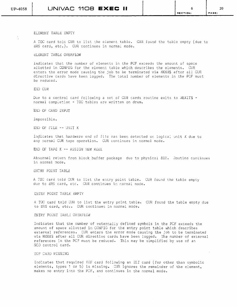
UP-40S8 UNIVAC 1108 EXEC II 6 SECTION:
ELEMENT TABLE EMPTY
A TOC card told CUR to list the element table. CUR found the table empty (due to ERS card, etc.). CUR continues in normal mode.
ELEMENT TABLE OVERFLOW
Indicates that the number of elements in the PCF exceeds the amount of space allotted in CONFIG for the element table which describes the elements. CUR enters the error mode causing the job to be terminated via MXXX$ after all CUR directive cards have been logged. The total number of elements in the PCF must be reduced.
END CUR
Due to a control card following a set of CUR cards routine exits to JW=XIT$ -normal completion - TOC tables are written on drum.
END OF CARD INPUT
Impossible.
END OF FILE UNIT X
Indicates that hardware end of file has been detected on logical unit X due to any normal CUR tape operation. CUR continues in normal mode.
END OF TAPE X -- ASSIGN NEW REEL
PAGE:
Abnormal return from block buffer package due to physical EOT. Routine continues in normal mode.
ENTRY POINT TABLE
A TOC card told CUR to list the entry point table. CUR found the table empty due to ERS card, etc. CUR continues in normal mode.
ENTRY POINT TABLE EMPTY
A TOC card told CUR to list the entry point table. CUR found the table empty due to ERS card, etc •• CUR continues in normal mode.
ENTRY POINT TABL= OVERFLOW
Indicates that the number of externally defined symbols in the PCF exceeds the amount of space allotted in CONFIG for the entry pOint table which describes external references. CUR enters the error mode causing the job to be terminated via MXXX$ after all CUR directive cards have been logged. The number of external references in the PCF must be reduced. This may be simplified by use of an SCD control card.
EOF CARD MISSING
Indicates that required EOF card following an ELT card (for other than symbolic elements, types 1 or 5) is missing. CUR ignores the remainder of the element, makes no entry into the peF, and continues in the normal mode.
20

UP-40S8 UNIVAC 110B EXEC II 6 SECTION:
ILLEGAL CHARACTER-DATE FIELD
Indicates malformation of the date field on an ELT card. The field is ignored, and CUR gets the required information from the resident, and proceeds normally.
ILLEGAL CHARACTER-TIME FIELD
Indicates malformation of the time field on an ELT card. The field is ignored, and CUR gets the required information from the resident, and proceeds normally.
ILLEGAL CONTROL CARD IN ELEMENT
PAGE:
A control card other than an EOF card was found within an element. The offending element is ignored, and CUR proceeds normally.
ILLEGAL TYPE DESIGNATION
Type field on ELT card is not 1, 2, 3, 4, 5, 6, or 7. The element is taken to be type 1 (symbolic). CUR enters the error mode, and proceeds.
IMPROPER FILE DESCRIPTION TABLE
Error return from block buffer - due to a previous CUR card routine goes to error and attempts to continue. However one more error causes CUR to terminate via MXXX$ after logging all directive cards.
NAME/VERSION HAS BEEN DELETED
Indicates that the element NAME/VERSION called for in a CUR directive is not in the PCR. CUR proceeds in normal mode. The directive which caused the diagnostic is ignored.
NAME/VERSION HAS NO PREAMBLE
Indicates that the element NAME/VERSION called for in a CUR directive requiring an element with a preamble (such as a relocatable element, type 3) is not in the PCF in proper form, CUR proceeds in normal mode, ignoring the directive.
NAME/VERSION NOT IN COMPLEX
Indicates that the element NAME/VERSION called for in a CUR directive is not in the PCF. CUR proceeds in normal mode. The directive which caused the diagnostic is ignored.
NAME/VERSION NOT ON TAPE X
Indicates that the element NAME/VERSION called for in a CUR tape directive is not in the logical unit X. This may be due to mispositioned tape. CUR proceeds normally. The directive which caused the diagnostic is ignored.
PROCEDURE
Identifies a type 7 element on a table of contents listing.
PROCEDURE NAME TABLE
Heading for TOC listing of procedure names.
21
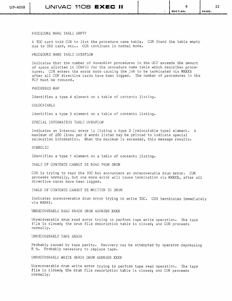
UP-40S8 UNIVAC 1108 EXEC II 6 SECTION:
PROCEDURE NAME TABLE EMPTY
A TOC card told CUR to list the procedure name table. CUR found the table empty due to ERS card, etc •• CUR continues in normal mode.
PROCEDURE NAME TABLE OVERFLOW
Indicates that the number of Assembler procedures in the OCF exceeds the amount of space allotted in CONFIG for the procedure name table which describes procedures. CUR enters the error mode causing the job to be terminated via MXXX$ , after all CUR directive cards have been logged. The number of procedures in the PCF must be reduced.
PROCESSED MAP
Identifies a type 4 element on a table of contents listing.
RELOCATABLE
Identifies a type 3 element on a table of contents listing.
SPECIAL INFORMATION TABLE OVERFLOW
Indicates an internal error is listing a type 3 (relocatable type) element. A maximum of 200 lines per 8 words listed may be printed to indicate special relocation information. When the maximum is exceeded, this message results.
SYMBOLIC
Identifies a type 1 element on a table of contents listing.
TABLE OF CONTENTS CANNOT BE READ FROM DRUM
CUR is trying to read the TOC but encounters an unrecoverable drum error. CUR proceeds normally, but one more error will cause termination via MXXX$, after all directive cards have been logged.
TABLE OF CONTENTS CANNOT BE WRITTEN TO DRUM
PAGE:
Indicates unrecoverable drum error trying to write TOC. CUR terminates immediately via MXXX$.
UNRECOVERABLE READ ERROR DRUM ADDRESS XXXX
Unrecoverable drum read error trying to perform tape write operation. The tape file is closed; the drum file description table is closed; and CUR proceeds normally.
UNRECOVERABLE TAPE ERROR
Probably caused by tape parity. Recovery may be attempted by operator depressing R 5. Probably necessary to replace tape.
UNRECOVERABLE WRITE ERROR DRUM ADDRESS XXXX
Unrecoverable drum write error trying to perform tape read operation. The tape file is closed; the drum file description table is closed; and CUR proceeds normally.
22
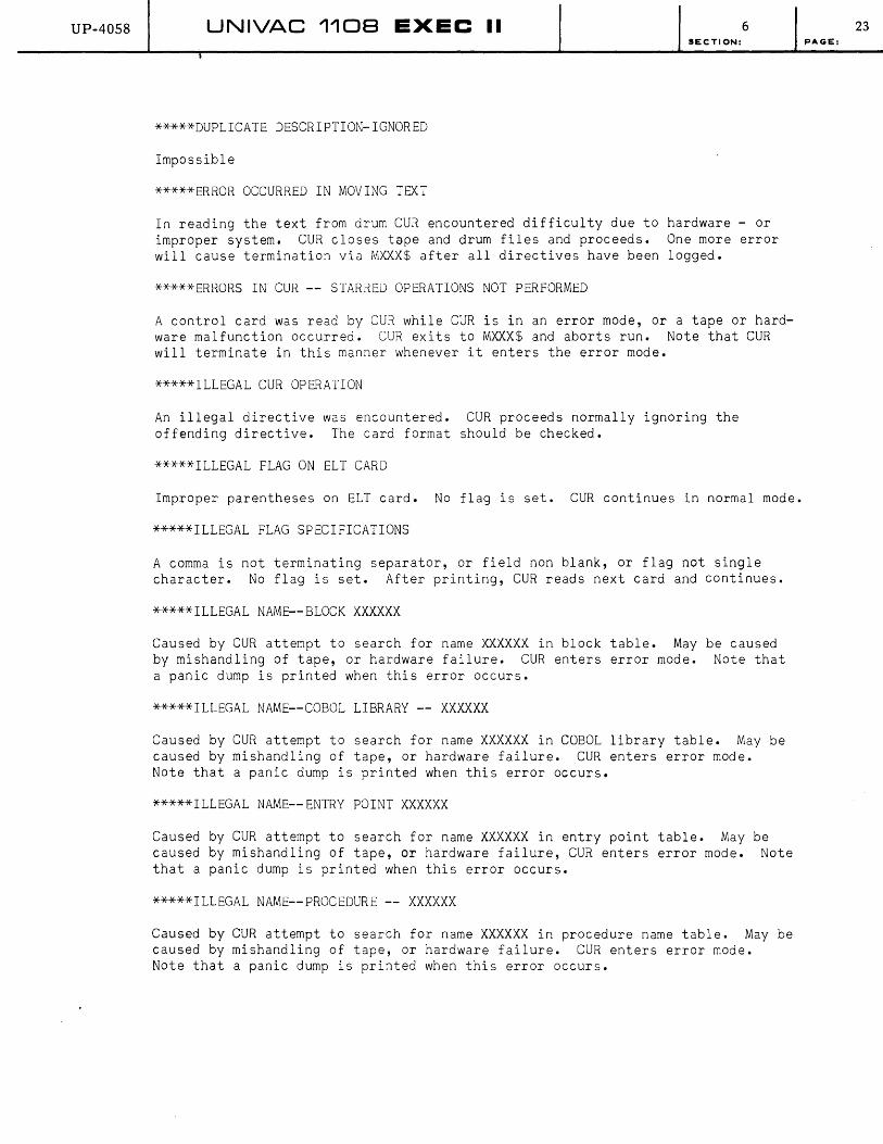
UP-40S8 UNIVAC 1108 EXEC II 6 SECTION:
*****DUPLICATE DESCRIPTION-IGNORED
Impossible
*****ERROR OCCURRED IN MOVING TEXT
In reading the text from drum CUR encountered difficulty due to hardware - or improper system. CUR closes tape and drum files and proceeds. One more error will cause termination via MXXX$ after all directives have been logged.
*****ERRORS IN CUR -- STARRED OPERATIONS NOT PERFORMED
A control card was read by CUR while CUR is in an error mode, or a tape or hardware malfunction occurred. CUR exits to MXXX$ and aborts run. Note that CUR will terminate in this manner whenever it enters the error mode.
*****ILLEGAL CUR OPERATION
An illegal directive was encountered. CUR proceeds normally ignoring the offending directive. The card format should be checked.
*****ILLEGAL FLAG ON ELT CARD
Improper parentheses on ELT card. No flag is set. CUR continues in normal mode.
*****ILLEGAL FLAG SPECIFICATIONS
A comma is not terminating separator, or field non blank, or flag not single character. No flag is set. After printing, CUR reads next card and continues.
*****ILLEGAL NAME--BLOCK XXXXXX
Caused by CUR attempt to search for name XXXXXX in block table. May be caused by mishandling of tape, or hardware failure. CUR enters error mode. Note that a panic dump is printed when this error occurs.
*****ILLEGAL NAME--COBOL LIBRARY -- XXXXXX
Caused by CUR attempt to search for name XXXXXX in COBOL library table. May be caused by mishandling of tape, or hardware failure. CUR enters error mode. Note that a panic dump is printed when this error occurs.
*****ILLEGAL NAME--ENTRY POINT XXXXXX
Caused by CUR attempt to search for name XXXXXX in entry point table. May be caused by mishandling of tape, or hardware failure, CUR enters error mode. Note that a panic dump is printed when this error occurs.
*****ILLEGAL NAME--PROCEDURE XXXXXX
Caused by CUR attempt to search for name XXXXXX in procedure name table. May be caused by mishandling of tape, or hardware failure. CUR enters error mode. Note that a panic dump is printed when this error occurs.
23 PAGE:
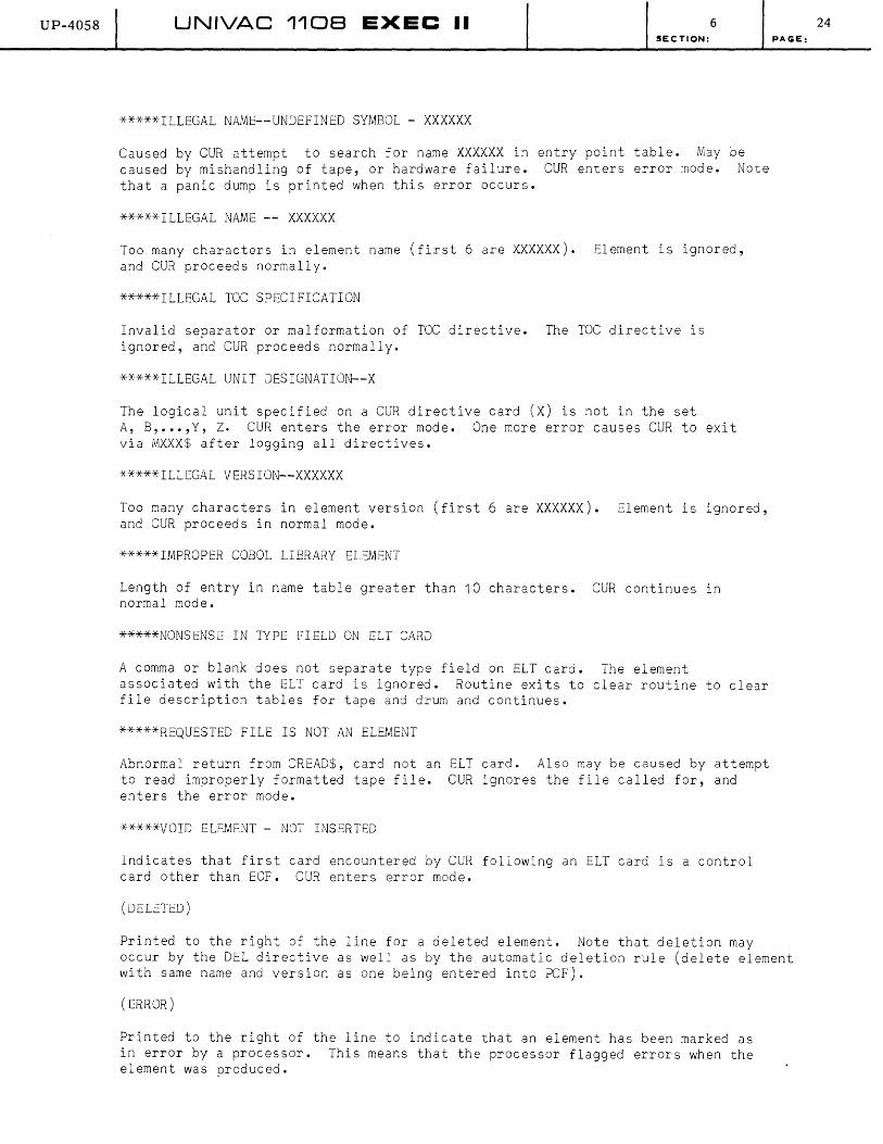
UP-40S8 UNIVAC 1108 EXEC II 6 SECTION:
*****ILLEGAL NAME--UNDEFINED SYMBOL - XXXXXX
Caused by CUR attempt to search for name XXXXXX in entry point table. May be caused by mishandling of tape, or hardware failure. CUR enters error mode. Note that a panic dump is printed when this error occurs.
*****ILLEGAL NAME XXXXXX
Too many characters in element name (first 6 are XXXXXX). Element is ignored, and CUR proceeds normally.
*****ILLEGAL TOC SPECIFICATION
Invalid separator or malformation of TOC directive. The TOC directive is ignored, and CUR proceeds normally.
*****ILLEGAL UNIT DESIGNATION--X
The logical unit specified on a CUR directive card (X) is not in the set A, B, ••• ,Y, Z. CUR enters the error mode. One more error causes CUR to exit via MXXX$ after logging all directives.
*****ILLEGAL VERSION--XXXXXX
Too many characters in element version (first 6 are XXXXXX). Element is ignored, and CUR proceeds in normal mode.
*****IMPROPER COBOL LIBRARY ELEMENT
Length of entry in name table greater than 10 characters. CUR continues in normal mode.
*****NONSENSE IN TYPE FIELD ON ELI CARD
A comma or blank does not separate type field on ELT card. The element associated with the ELT card is ignored. Routine exits to clear routine to clear file description tables for tape and drum and continues.
*****REQUESTED FILE IS NOT AN ELEMENT
Abnormal return from CREAD$, card not an ELT card. Also may be caused by attempt to read improperly formatted tape file. CUR ignores the file called for, and enters the error mode.
*****VOID ELEMENT - NOT INSERTED
Indicates that first card encountered by CUR following an ELT card is a control card other than EOF. CUR enters error mode.
(DELETED)
PAGE:
Printed to the right of the line for a deleted element. Note that deletion may occur by the DEL directive as well as by the automatic deletion rule (delete element with same name and version as one being entered into PCF).
(ERROR)
Printed to the right of the line to indicate that an element has been marked as in error by a processor. This means that the processor flagged errors when the element was produced.
24

UP-4058 UNIVAC 1108 EXEC II 6 SECTION: PAGE:
6.D. ALLOCATOR PRINTER MESSAGES
AMBIGUITY FOR ENTRY POINT NNNNNN
The undefined symbol NNNNNN in the element whose name precedes this message matches more than one entry point in the user PCF, or it matches none in the user PCF and more than one in the library PCF. The symbol is given the value zero (no relocation), and the output of the allocator fs marked as an e-rror element.
AMBIGUITY IN COMPLEX ELEMENTS
The element whose name precedes this message has more than one definition as in either the user PCF or the library PCF. One of these is selected arbitrarily, and the allocator output is marked as an error element.
ABS NAME NOT FOUND
No element in either the user or library PCF has the name designated on the ABS control card. The allocator exits immediately via MEXIT$.
ALLOCATION TABLE OVERFLOW
This 8700 word table contains information regarding elements included in the allocation. Approximate number of words required of this table for each element is:
2 x (highest location counter used) + 7 + 9 x (number of common blocks defined by element).
The allocator exits immediately via MEXIT$.
BLANK COMMON
Normal part of allocator listing for program containing blank common area. The limits of the area are also printed.
BLOCK DEFINITIONS
Normal part of allocator listing when L option is used on control card. This message acts as a header for information on common blocks, including block names, control counters used, and length of block.
BLOCK TABLE OVERFLOW
This table contains 3 words of information per named common block. The maximum allowed is 92 blocks (276 words). The allocator exits immediately via MEXIT$.
BLOCK XXX DEFINED INDEPENDENT-MAP DEPENDENCY DEFINITION USED
Indicates that the block is defined as independent (common) on an INFO card, but defined as dependent by MAP. One possible cause of this is a missing BLK directive. The MAP definition is used, i.e., the block is not defined as common.
25
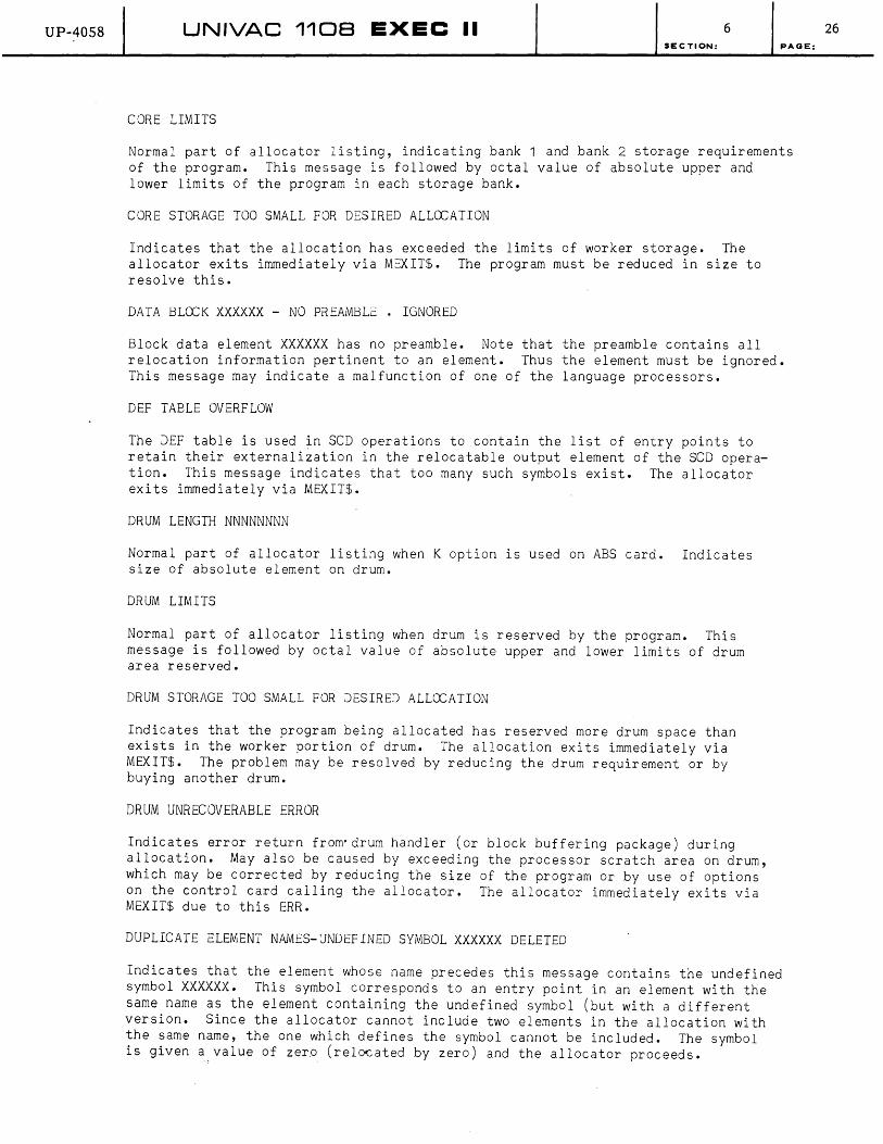
UP-4058 UNIVAC 1108 EXEC II 6 SECTION: PAGE:
CORE LIMITS
Normal part of allocator listing, indicating bank 1 and bank 2 storage requirements of the program. This message is followed by octal value of absolute upper and lower limits of the program in each storage bank.
CORE STORAGE TOO SMALL FOR DESIRED ALLOCATION
Indicates that the allocation has exceeded the limits of worker storage. The allocator exits immediately via MEXIT$. The program must be reduced in size to resolve this.
DATA BLOCK XXXXXX - NO PREAMBLE . IGNORED
Block data element XXXXXX has no preamble. Note that the preamble contains all relocation information pertinent to an element. Thus the element must be ignored. This message may indicate a malfunction of one of the language processors.
DEF TABLE OVERFLOW
The DEF table is used in SCD operations to contain the list of entry points to retain their externalization in the relocatable output element of the SCD operation. This message indicates that too many such symbols exist. The allocator exits immediately via MEXIT$.
DRUM LENGTH NNNNNNNN
Normal part of allocator listing when K option is used on ABS card. Indicates size of absolute element on drum.
DRUM LIMITS
Normal part of allocator listing when drum is reserved by the program. This message is followed by octal value of absolute upper and lower limits of drum area reserved.
DRUM STORAGE TOO SMALL FOR DESIRED ALLOCATION
Indicates that the program being allocated has reserved more drum space than exists in the worker portion of drum. The allocation exits immediately via MEXIT$. The problem may be resolved by reducing the drum requirement or by buying another drum.
DRUM UNRECOVERABLE ERROR
Indicates error return from'drum handler (or block buffering package) during allocation. May also be caused by exceeding the processor scratch area on drum, which may be corrected by reducing the size of the program or by use of options on the control card calling the allocator. The allocator immediately exits via MEXIT$ due to this ERR.
DUPLICATE ELEMENT NAMES-UNDEFINED SYMBOL XXXXXX DELETED
Indicates that the element whose name precedes this message contains the undefined symbol XXXXXX. This symbol corresponds to an entry point in an element with the same name as the element containing the undefined symbol (but with a different version. Since the allocator cannot include two elements in the allocation with the same name, the one which defines the symbol cannot be included. The symbol is given a value of zer.o (relocated by zero) and the allocator proceeds.
26

UP-4058 UNIVAC 1108 EXEC II 6 SECTION:
ELEMENT ABSOLUTE - DELETED FROM ALLOCATION
Indicates that the element whose name/version precedes this message exists in the PCF only in absolute form (type 2). The allocator proceeds, deleting the element and all references to it. This error can be corrected by placing a relocatable element with the correct name/version into the user PCF, or by making all references to the element call for a relocatable element.
ELEMENT NOT IN COMPLEX - DELETED FROM ALLOCATION
An element named thru MAP is not in the user or library PCF and is therefore deleted. If version is used, version must appear in the PCF. Allocator proceeds after deletion.
END OF ALLOCATION
Normal part of allocator listing indicating completion.
ENTRY POINT XXXXXX NOT FOUND FOR AUTO LOAD-IGNORED
An entry point in an element d¥signated for auto-loading was not found. Impossible if allocator is functioning normally.
EQUIVOCAL ELEMENTS IN COMPLEX-DELETED FROM ALLOCATION
PAGE:
Two or more elements in the user PCF have the name/version preceding this message. The allocator deletes the element and all references to it, and proceeds.
EXECUTION AREA EXCEEDED
The completed program is too large to fit in the execution area on drum. Allocator exits immediately via MEXIT$. Note that use of E option on the control card calling the allocator suppresses this message and subsequent action. However the PCF is destroyed in this case.
EXTERNAL DEFINITION NAMED IN DEF OPERATION NOT FOUND-IGNORED
The symbol preceding this message was found on a DEF card (under MAP), but was not among the entry points found in the elements included in this SCD operation.
EXTERNAL DEFINITIONS
Normal part of allocator listing when L option is used on control card. This message acts as header for information on entry points, including the label and absolute location of each entry point in the element.
EXTERNAL REFERENCES
Normal part of allocator listing when L option is used on control card. This message acts as header for information on undefined symbols in each original relocatable element in the allocation, including label and the name of the element containing the entry point corresponding to the reference.
ILLEGAL STRUCTURE FOR AN SCD ALLOCATION
Indicates that a call was made during allocation to include MAUTO$, thereby indicating segmentation. This is illegal for an SCD operation. The allocator exits immediately via MEXIT$.
27
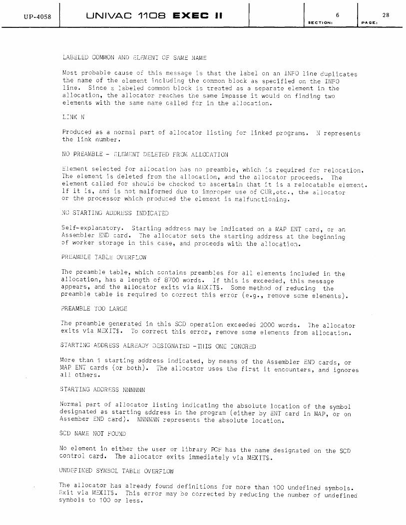
UP-40S8 UNIVAC 1108 EXEC II 6 SECTION:
LABELED COMMON AND ELEMENT OF SAME NAME
Most probable cause of this message is that the label on an INFO line duplicates the name of the element including the common block as specified on the INFO line. Since a labeled common block is treated as a separate element in the allocation, the allocator reaches the same impasse it would on finding two elements with the same name called for in the allocation.
LINK N
Produced as a normal part of allocator listing for linked programs. N represents the link number.
NO PREAMBLE - ELEMENT DELETED FROM ALLOCATION
PAGE:
Element selected for allocation has no preamble, which is required for relocation. The element is deleted from the allocation, and the allocator proceeds. The element called for should be checked to ascertain that it is a relocatable element. If it is, and is not malformed due to improper use of CUR,etc., the allocator or the processor which produced the element is malfunctioning.
NO STARTING ADDRESS INDICATED
Self-explanatory. Starting address may be indicated on a MAP ENT card, or an Assembler END card. The allocator sets the starting address at the beginning of worker storage in this case, and proceeds with the allocation.
PREAMBLE TABLE OVERFLOW
The preamble table, which contains preambles for all elements included in the allocation, has a length of 8700 words. If this is exceeded, this message appears, and the allocator exits via MEXIT$. Some method of reducing the preamble table is required to correct this error (e.g., remove some elements).
PREAMBLE TOO LARGE
The preamble generated in this SCD operation exceeded 2000 words. The allocator exits via MEXIT$. To correct this error, remove some elements from allocation.
STARTING ADDRESS ALREADY DESIGNATED -THIS ONE IGNORED
More than 1 starting address indicated, by means of the Assembler END cards, or MAP ENT cards (or both). The allocator uses the first it encounters, and ignores all others.
STARTING ADDRESS NNNNNN
Normal part of allocator listing indicating the absolute location of the symbol designated as starting address in the program (either by eNT card in MAP, or on Assember END card). NNNNNN represents the absolute location.
SCD NAME NOT FOUND
No element in either the user or library PCF has the name designated on the SCD control card. The allocator exits immediately via MEXIT$.
UNDEFINED SYMBOL TABLE OVERFLOW
The allocator has already found definitions for more than 100 undefined symbols. Exit via MEXIT$. This error may be corrected by reducing the number of undefined symbols to 100 or less.
28
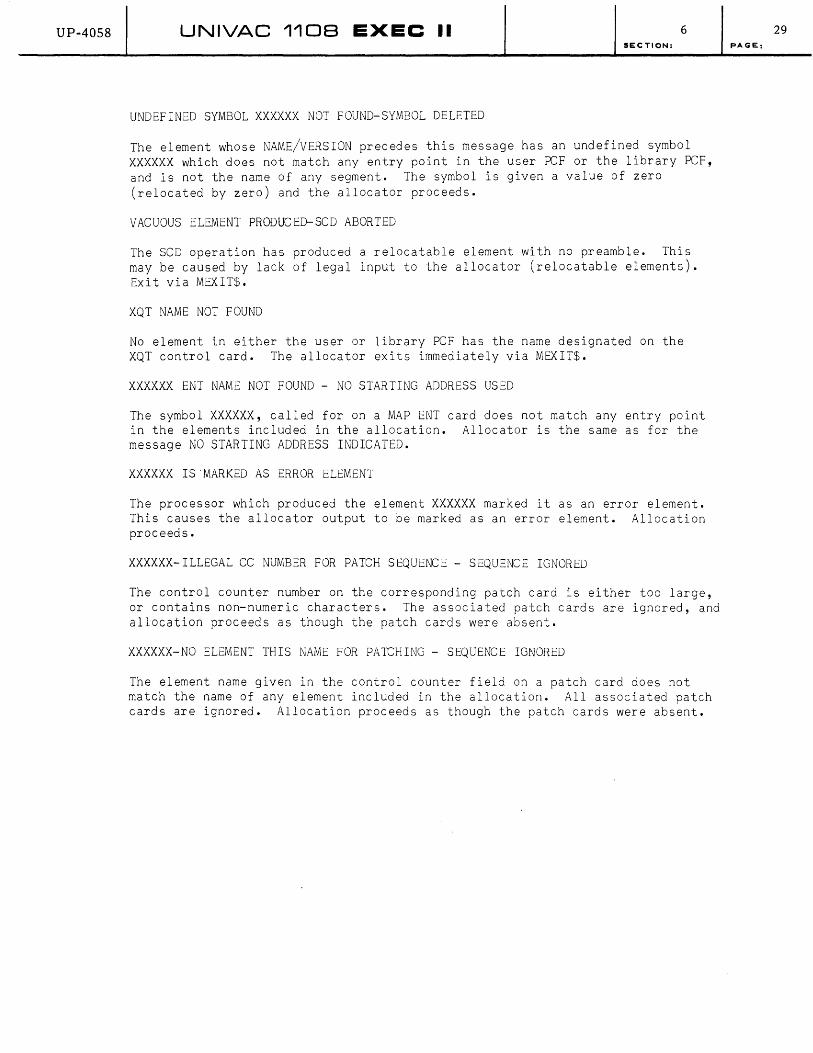
UP-40S8 UNIVAC 1108 EXEC II 6 SECTION:
UNDEFINED SYMBOL XXXXXX NOT FOUND-SYMBOL DELETED
The element whose NAME/VERSION precedes this message has an undefined symbol XXXXXX which does not match any entry point in the user PCF or the library PCF, and is not the name of any segment. The symbol is given a value of zero (relocated by zero) and the allocator proceeds.
VACUOUS ELEMENT PRODUCED-SCD ABORTED
The SCD operation has produced a relocatable element with no preamble. This may be caused by lack of legal input to the allocator (relocatable elements). Ex i t v i a MEX I T$ •
XQT NAME NOT FOUND
No element in either the user or library PCF has the name designated on the XQT control card. The allocator exits immediately via MEXIT$.
XXXXXX ENT NAME NOT FOUND - NO STARTING ADDRESS USED
The symbol XXXXXX, called for on a MAP ENT card does not match any entry point in the elements included in the allocation. Allocator is the same as for the message NO STARTING ADDRESS INDICATEJ.
XXX XXX IS 'MARKED AS ERROR ELEMENT
The processor which produced the element XXXXXX marked it as an error element. This causes the allocator output to be marked as an error element. Allocation proceeds.
XXXXXX-ILLEGAL CC NUMBER FOR PATCH SEQUENCE - SEQUENCE IGNORED
The control counter number on the corresponding patch card is either too large, or contains non-numeric characters. The associated patch cards are ignored, and allocation proceeds as though the patch cards were absent.
XXXXXX-NO ELEMENT THIS NAME FOR PATCHING - SEQUENCE IGNORED
The element name given in the control counter field on a patch card does not match the name of any element included in the allocation. All associated patch cards are ignored. Allocation proceeds as though the patch cards were absent.
29 PAGE:

UP-40S8 UNIVAC 110B EXEC II 6 SECTION:
6.E. MAP PRINTER MESSAGES
A COMMA FOLLOWS A C
The character C (slash, paren, etc.) is followed by a comma thus creating illegal segment construction. The card is scanned for further errors and then deleted. The output element is marked as an error element. MAP proceeds normally.
A RIGHT PAREN FOLLOWS A C
PAGE:
The character C (slash, comma, etc.) is followed by a right paren thus creating illegal segment construction. The card is scanned for further errors and then deleted. The output element is marked as an error element, MAP proceeds normally.
ALPHABETIC SYMBOL DETECTED - DRUM FIX OMITTED
The drum address on a FIX card begins with an alphabetic. The card is scanned for further errors and then deleted. The output element is marked as an error element. MAP proceeds normally.
BLANK FOLLOWS NAME - UNBALANCED PARENTHESES
The card was terminated with a blank with unbalanced parens. MAP continues to scan the card to try to rectify the error. The card is used if parens balance at end-of-card. The output element is unaffected by this war0ing. MAP proceeds normally.
CHN CARD HAS NO LINK NUMBER
The link introduced by this CHN card has no number to distinguish it from other links. The card is scanned for further errors and then deleted. The output element is marked as an error element. MAP proceeds normally.
COMMA AT FIRST LEVEL
A comma was detected by the card scan routine without first encountering a parenthesis. The card is scanned for further errors and then deleted. The output element is marked as an error element. MAP proceeds normally.
CORRECTION CARD IN ERROR
An erroneous correction card was encountered. No output element is produced and MAP exits via MEXIT$.
DEF TABLE EXCEEDED
Too many DEF entries. The output element is marked as an error element. MAP proceeds normally.
30

UP-4058 UNIVAC 110B EXEC II 6 SECTION:
DUPLICATE LINK NUMBER
Two CHN cards have the same number. The output element is marked as an error element. MAP proceeds normally.
END OF BLK TABLE - TOO MANY BLKS
More than 30 blocks are defined. No output element is produced and MAP exits via MEX IT$.
END OF FIX TABLE - TOO MANY REFS
More than 166 FIX cards were processed. No output element is produced and MAP exits via MEXIT$.
END OF SEG NAME TABLE - TOO MANY SEGS
More than 100 segments named on SEG cards call for separate loads. No output element is produced and MAP exits via MEXIT$.
END OF SET TABLE - TOO MANY REFS TO SET
More than 20 SET cards for one bank of storage or for drum have been processed. No output element is produced and MAP exits via MEXIT$.
ERROR IN SECOND DRUM ADDRESS
The second drum address on a SET card begins with a non-numeric character. The card is scanned for further errors and then deleted. The output element is marked as an error element. MAP proceeds normally.
EXTRANEOUS PARENTHESES
More parentheses than necessary were used on a SEG card. The card is used by MAP in any event. The output element is unaffected by this warning. MAP proceeds normally.
FIRST ENT NAME REPLACED
Two ENT cards were processed in the current link. The output element is unaffected by this warning.
MAP CARD FOLLOWED BY CONTROL CARD
The second of these is used. MAP proceeds normally.
Another control card followed the MAP card. No output element is produced and MAP exits via MEXIT$.
MORE THAN ONE 'ELEMENT HAS THE NAME XXXXXX
The name XXXXXX appears on two BLK cards in the link. The output element is unaffected by this warning. MAP proceeds normally.
NAME AND VERSION NOT SEPARATED BY A /
Incorrect specification on a USE card (illegal character). The card is scanned for further errors and then deleted. The output element is marked as an error element. MAP proceeds normally.
31 PAGE:
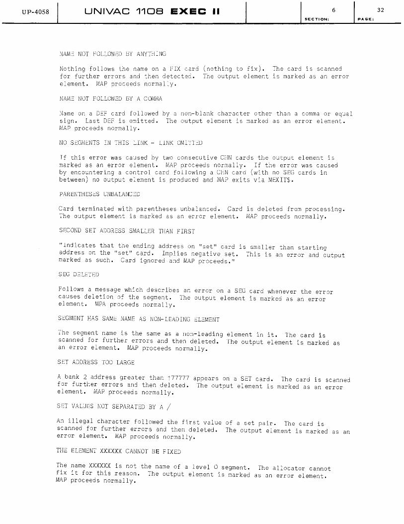
UP-4058 UNIVAC 110B EXEC II 6
SECTION:
NAME NOT FOLLOWED BY ANYTHING
Nothing follows the name on a FIX card (nothing to fix). The card is scanned for further errors and then detected. The output element is marked as an error element. MAP proceeds normally.
NAME NOT FOLLOWED BY A COMMA
Name on a D=F card followed by a non-blank character other than a comma or equal sign. Last DEF is omitted. The output element is marked as an error element. MAP proceeds normally.
NO SEGMENTS IN THIS LINK - LINK OMITTED
If this error was caused by two consecutive CHN cards the output element is marked as an error element. MAP proceeds normally. If the error was caused by encountering a control card following a CHN card (with no SEG cards in between) no output element is produced and MAP exits via MEXIT$.
PARENTHESES UNBALANCED
Card terminated with parentheses unbalanced. Card is deleted from processing. The output element is marked as an error element. MAP proceeds normally.
SECOND SET ADDRESS SMALLER THAN FIRST
"Indicates that the ending address on "set" card is smaller than starting address on the "set" card. Implies negative set. This is an error and output marked as such. Card ignored and MAP proceeds."
SEG DELETED
Follows a message which describes an error on a SEG card whenever the error causes deletion of the segment. The output element is marked as an error element. MPA proceeds normally.
SEGMENT HAS SAME NAME AS NON-LEADING ELEMENT
The segment name is the same as a non-leading element in it. The card is scanned for further errors and then deleted. The output element is marked as an error element. MAP proceeds normally.
SET ADDRESS TOO LARGE
A bank 2 address greater than 177777 appears on a SET card. The card is scanned for further errors and then deleted. The output element is marked as an error element. MAP proceeds normally.
SET VALUES NOT SEPARATED BY A /
An illegal character followed the first value of a set pair. The card is scanned for further errors and then deleted. The output element is marked as an error element. MAP proceeds normally.
THE ELEMENT XXXXXX CANNOT BE FIXED
The name XXXXXX is not the name of a level 0 segment. The allocator cannot fix it for this reason. The output element is marked as an error element. MAP proceeds normally.
32
PAGE:
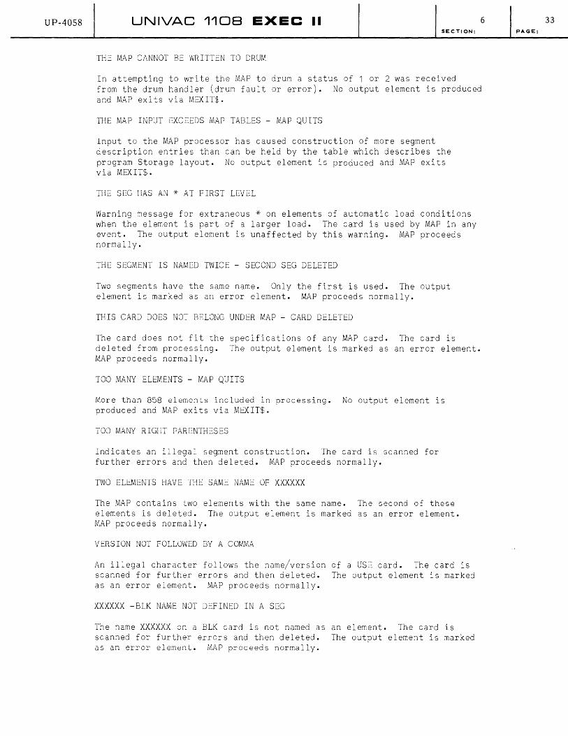
UP-40S8 UNIVAC 110B EXEC II 6 SECTION:
THE MAP CANNOT BE WRITTEN TO DRUM
In attempting to write the MAP to drum a status of 1 or 2 was received from the drum handler (drum fault or error). No output element is produced and MAP exits via MEXIT$.
THE MAP INPUT EXCEEuS MAP TABLES - MAP QUITS
Input to the MAP processor has caused construction of more segment description entries than can be held by the table which describes the program Storage layout. No output element is produced and MAP exits via MEXIT$.
THE SEG HAS AN * AT FIRST LEVEL
Warning message for extraneous * on elements of automatic load conditions when the element is part of a larger load. The card is used by MAP in any event. The output element is unaffected by this warning. MAP proceeds normally.
THE SEGMENT IS NAMED TWICE - SECOND SEG DELETED
Two segments have the same name. Only the first is used. The output element is marked as an error element. MAP proceeds normally.
THIS CARD DOES NOT BELONG UNDER MAP - CARD DELETED
The card does not fit the specifications of any MAP card. The card is deleted from processing. The output element is marked as an error element. MAP proceeds normally.
TOO MANY ELEMENTS - MAP QUITS
More than 858 elements included in processing. No output element is produced and MAP exits via MEXIT$.
TOO MANY RIGHT PARENTHESES
Indicates an illegal segment construction. The card is scanned for further errors and then deleted. MAP proceeds normally.
TWO ELEMENTS HAVE THE SAME NAME OF XXXXXX
The MAP contains two elements with the same name. The second of these elements is deleted. The output element is marked as an error element. MAP proceeds normally.
VERSION NOT FOLLOWED BY A COMMA
An illegal character follows the name/version of a USE card. The card is scanned for further errors and then deleted. The output element is marked as an error element. MAP proceeds normally.
XXXXXX -BLK NAME NOT DEFINED IN A SEG
The name XXXXXX on a BLK card is not named as an element. The card is scanned for further errors and then deleted. The output element is marked as an error element. MAP proceeds normally.
33 PAGE:

UP-4058 UNIVAC 1108 EXEC II 6 SECTION:
6.F. PMD PRINTER MESSAGES
BLANK COMMON
Printed as a heading if a blank common area exists. Routine continues in normal mode - no operator intervention.
CHANGED WORDS
PMD option specified print words that changed. Routine continues - no operator intervention.
DRUM READ ERROR-NO DUMP POSSIBLE
Drum error. Routine exits from PMD via MEXIT$.
ELEMENT NOT ACTIVE
If element is not marked as active in ATAB, (i.e., MAP said--segment A-B,C and tried to dump A), routine exits to check for B option and will finally exit from PMD.
INFO NOT AVAILABLE
The limits of the dumped area on drum do not include the info requested. PMD continues and sets length to dump to O. May result from dumping a FIXed element.
NO CONTINUATION CARD FOUND
. PAGE:
CREAD$ read a control card. It expected a continuation of previous card. Routine continues without operator intervention. It stays in PMD to work card.
OPTION LETTER-A-ASSUMED--DUMP OF SEGXXXXXX
If ELT name not in ATAB, but is in the segment name table, routine processes segment; no operator intervention.
SPEC NAME NOT FOUND
ELT or ELT name not in ATAB or SEG name table. Routine continues and requires no intervention.
34

UP-4058 UNIVAC 1108 EXEC II 6 SECTION: PAGE:
E.7. LIBRY (LIBRARY CREATE ROUTINE) PRINT MESSAGES
INPUT-OUTPUT ERROR DEC TED
Probably caused by unrecoverable drum error. Followed by message LIBRARY PROBABLY DESTROYED.
LIBRARY BLOCK TABLE SIZE EXCEEDED
Indicates that user PCF block table will not fit into area in library PCF assigned for block table. Size of tables is determined by a constant in CONFIG which is installation-variable. Always followed by message NEW LIBRARY NOT WRITTEN.
LIBRARY COBOL COpy TABLE EXCEEDED
Indicates that user PCF COBOL library table will not fit into corresponding area in library PCF. Size of tables is determined by ~ constant in CONFIG which is installation-variable. Always followed by message NEW LIBRARY NOT WRITTEN.
LIBRARY ELEMENT TABLE SIZE EXCEEDED
Indicates that user PCF element table will not fit into corresponding area in library PCF. Size of tables is determined by a constant in CONFIG which is installation-variable. Always followed by message NEW LIBRARY NOT WRITTEN.
LIBRARY ENTRY POINT TABLE SIZE EXCEEDED
Indicates that entry point table in user PCF will not fit into corresponding area in library PCF. Size of tables is determined by a constant in CONFIG which is installation-variable. Always followed by message NEW LIBRARY NOT WRITTEN.
LIBRARY PROBABLY DESTROYED.
Indicates I/O difficulty occurred. Routine exits via MXXX$.
LIBRARY PROCEDURE NAME TABLE EXCEEDED
Indicates that user procedure name table will not fit into corresponding area in library PCF. Size of tables is determined by a constant in CONFIG which is installation-variable. Always followed by message NEW LIBRARY NOT WRITTEN.
LIBRARY PROGRAM FILE AREA EXCEEDED
Indicates that text in user PCF will not fit into text area in library PCF. Size of text areas are determined by an installation-variable constant in CONFIG. Always followed by message NEW LIBRARY NOT WRITTEN.
LIBRARY SUCCESSFULLY CONSTRUCTED
Indicates normal termination after new library is complete.
NEW LIBRARY NOT WRITTEN
Indicates that an overflow of some library area occurrad. The routine exits via MXXX$ without writing a library.
35
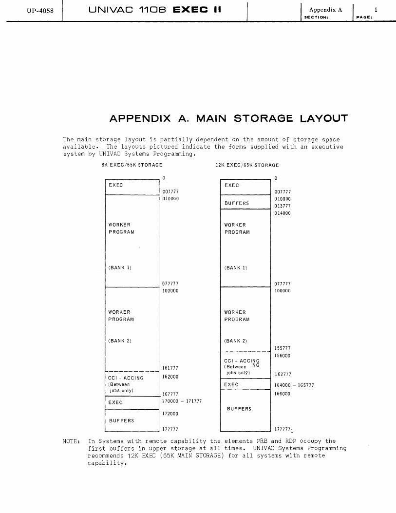
UP-40S8 UNIVAC 1108 EXEC II Appendix A SECTION:
APPENDIX A. MAIN STORAGE LAYOUT
The main storage layout is partially dependent on the amount of storage space available. The layouts pictured indicate the forms supplied with an executive system by UNIVAC Systems Programming.
8K EXEC/65K STORAGE
EXEC
WORKER
PROGRAM
(BANK 1)
WORKER
PROGRAM
(BANK 2)
-----------CCI + ACCING (Between jobs only)
EXEC
BUFFERS
o
007777
010000
077777
100000
161777
162000
167777
170000 - 171777
172000
177777
12K EXEC/65K STORAGE
EXEC
BUFFERS
WORKER
PROGRAM
(BANK 1)
WORKER
PROGRAM
(BANK 2)
-----------CCI + ACCING ( Between NG
jobs onl~)
EXEC
BUFFERS
o
007777
010000
013777
014000
077777
100000
155777
156000
162777
164000 - 165777
166000
NOTE: In Systems with remote capability the elements PRB and RDP occupy the first buffers in upper storage at all times. UNIVAC Systems Programming recommends 12K EXEC (65K MAIN STORAGE) for all systems with remote capability.
1 PAGE:

UP-4058 UNIVAC 1108 EXEC II Appendix B SECTION:
APPENDIX B. SYSTEM DRUM LAYOUT
The system drum layout is dependent upon the number of drums available. The layouts pictured in this appendix are of the form supplied with an executive system by UNIVAC Systems Programming.
PAGE:
Notice that the drum layout which is referred to as "1 DRUM EXTENDED" is physically a two drum system.
1. SINGLE-CHANNEL DRUM LAYOUT
1 DRUM 1 DRUM EXTENDED 2 DRUM
0 0 0 i I I
EXEC EXEC EXEC
I I J 035000 035000 035000
I I i Processors Processors Processors
I I I 0420000 0420000 0420000
I I i Library PCF Library PCF Library PCF
I I I 06000000 0600000 07000000
I I I Execution Area Execution Area Execution Area
I I I 01000000 01000000 01300000
I User PCF User PCF User PC F
I I I 02000000 02000000 03000000
I i i Processor Scratch Processor Scratch Processor Scratch
Area Area Area
1 1 1 02400000 05400000 05000000
I I i
Symboint Drum Symboint Drum Symboint Drum Buffers Buffers Buffers
1 l t 03000000 06000000 06000000
Drum layouts for up to 8 drums on a single channel are possible; such layouts will be similar to the above.
1
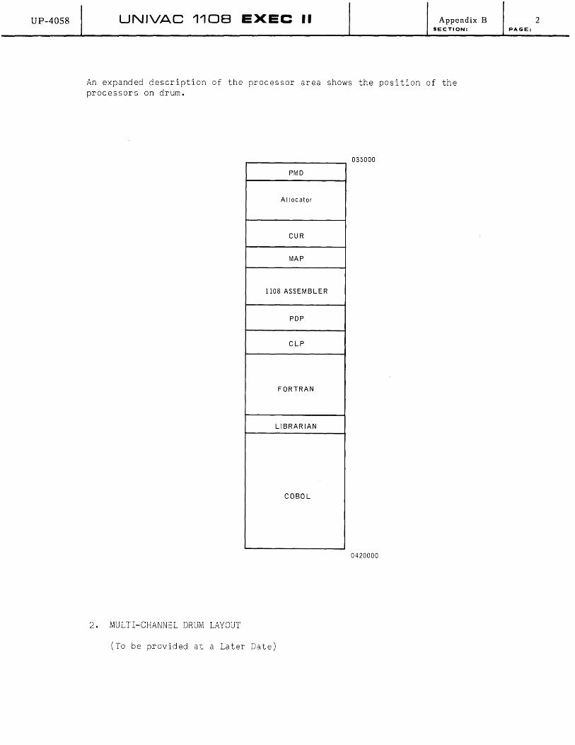
UP-4058 UNIVAC 1108 EXEC II Appendix B SECTION:
An expanded description of the processor area shows the position of the processors on drum.
035000
PMD
Allocator
CUR
MAP
1108 ASSEMBLER
PDP
ClP
FORTRAN
LIBRARIAN
COBOL
0420000
2. MULTI-CHANNEL DRUM LAYOUT
(To be provided at a Later Date)
2 PAGE:
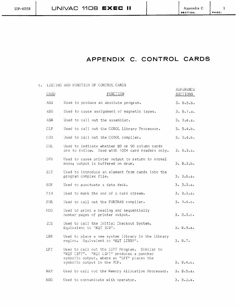
UP-40S8 UNIVAC 1108 EXEC II Appendix C SECTION:
APPENDIX C. CONTROL CARDS
1. LISTING AND FUNCTION OF CONTROL CARDS
ABS
ASG
ASM
CLP
COB
COL
DPR
ELI
EOF
FIN
FOR
HDG
ICS
LBR
LFT
MAP
MSG
REFERENCE FUNCTION SECTIONS
Used to produce an absolute program. 3. B.5.b.
Used to cause assignment of magnetic tapes. 3. B.1.a.
Used to callout the assembler. 3. B.4.a.
Used to callout the COBOL Library Processor. 3. B.4.b.
Used to callout the COBOL compiler. 3. B.4.b.
Used to indicate whether 80 or 90 column cards are to follow. Used with 1004 card readers only. 3. B.3.a.
Used to cause printer output to return to normal mode; output is buffered on drum. 3. B.3.b.
Used to introduce an element from cards into the program complex file. 3. B.6.a.
Used to punctuate a data deck. 3. B.3.a.
Used to mark the end of a card stream. 3. B.3.a.
Used to callout the FORTRAN compiler. 3. B.4.c.
Used to print a heading and sequentially number pages of printer output. 3. B.3.c.
Used to call the Initial Checkout System. Equivalent to "XQT lCS". 3. B.9.a.
Used to place a new system library in the library region. Equivalent to "XQT LIBRY". 3. B.7.
Used to callout the LIFT Program. Similar to "XQT LIFT". "XQT LIFT" produces a punched symbolic output, where as "LFT" places the symbolic output in the PCF. 3. B.4.c.
Used to callout the Memory Allocation Processor. 3. B.5.a.
Used to communicate with operator. 3. B.2.a.
1 PAGE:
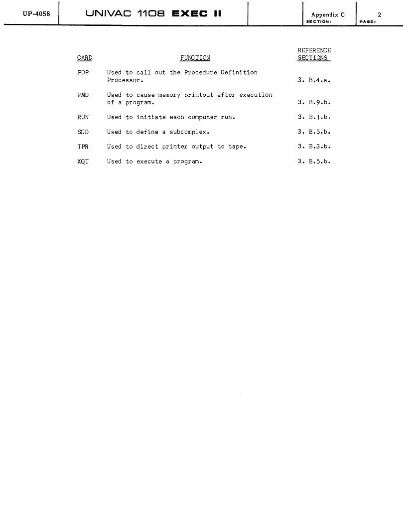
UP-4058 UNIVAC 1108 EXEC II
CARD FUNCTION
PDP Used to call out the Procedure Definition Processor.
PMD Used to cause memory printout after execution of a program.
RUN Used to initiate each computer run.
SCD Used to define a subcomplex.
TPR Used to direct printer output to tape.
XQT Used to execute a program.
Appendix C SECTION:
REFERENCE SECTIONS
3. B.4.a.
3. B.9.b.
3. B.1.b.
3. B.5.b.
3. B.3.b.
3. B.5.b.
2 PAGE:
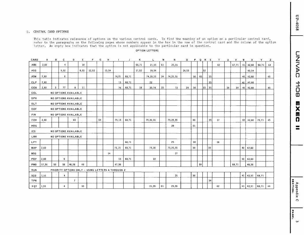
2. CONTROL CARD OPTIONS
This table indicates relevance of options on the various control cards. To find the meaning of an option on a particular control card, refer to the paragraphs on the following pages whose numbers appear in the box in the row of the contr01 card and the column of the option letter. An empty box indicates that the option is not applicable to the particular card in question.
OPTION LETTERS
CARD A B C D E F G H K L M N o P Q R T U v w x Y z ABS 2,60 4 10 66,71 21,55 61 25,55 62 67,71 41 42,60 68,71 44
ASG 5,52 9,53 12,52 13,54 17,52 19,54 28,53 32 43,54
ASM 2,60 6 74,15 68,71 74,20,55 24 74,25,55 30 65 35 40 42,60 45
CLP 2 60 15 68 71 22 35 40 4260
COB 2,60 3 77 8 11 76 68,71 18 20,78 23 72 29 30 33 35 38 39 40 42,60 45
COL NO OPTIONS AVAILABLE
DPR NO OPTIONS AVAILABLE
ELT NO OPTIONS AVAILABLE
EOF NO OPTIONS AVAILABLE
FIN NO OPTIONS AVAILABLE
FOR 2,60 63 64 75,15 68,71 75,20,55 75,25,55 30 35 37 40 42,60 70,71 45
HDG 26 31
ICS NO OPTIONS AVAILABLE
LBR NO OPTIONS AVAILABLE
LFT 68,71 25 30 36
MAP 2,60 73,15 68,71 73,20 73,25,55 30 35 40 42,60
MSG 14 27
PDP 2,60 6 15 68,71 22 40 42,60
PMD 57,56 50 58 46,56 49 47,56 59 68,71 48,56
RUN PRIORITY OPTIONS ONLY - USING LETTERS A THROUGH Z
seD 1,51 4 25 30 41 42,51 68,71
TPR 7 34
XQT 1,51 4 10 21,55 61 25,55 62 41 42,51 68,71 44
..
c: "0 I
"J::o. o (J1 00
c z ~ ()
~ ~
o m m )( m n --
~ > ~"O -"0 o I'D Z ::s •• 0..
'11 • Q III
~.
(')

UP-40S8 UNIVAC 1108 EXEC II Appendix C SECTION:
1. Accept Allocator output even if errors are detected. The option is not effective if the errors detected are of such a nature as to prevent the production of an absolute program.
2. Accept the output of the processor even if errors are detected.
3. Ignore check of sequence number (columns 1 through 6).
4. Insert patch cards.
5. Causes automatic Fieldata to BCD software conversion on output and automatic BCD to Fieldata software conversion on input. (For UNISERVO IIIC units only.
PAGE:
6. Corrections noted on source language listing. In the absence of this option, line inserts and deletions are starred to the right of the line(s) corrected.
7. Prepare tape in DLT-5 format. Reference Appendix D. 1. C ••
8. Print defining cluster in alphabetic order.
9. Parity set even.
10. Allow execution area to overflow into user FCF without diagnostics. Reference Sections 2 B.4. and 2 B.5. for implications of using this option. Responsibility rests with the user to insure that the program on the drum is not destroyed by use of this option.
11. Print detailed error diagnostics.
12. Causes automatic Fieldata to BCD hardware conversion to cease.
13. Density set high.
14. Turn on wait. Reference Section 3 B.2 ••
15. Single space listing. If this option is not specified, listing is double spaced.
17. Causes automatic Fieldata to BCD hardware conversion on output and automatic BCD to Fieldata hardware conversion on input. On 1107 this option applies only to IIIC units and automatically sets even parity (odd parity cannot be used). On 1108 this option applies to IVC, VIC and VIIIC units and odd parity is assumed unless the E option is used (either will be effective).
18. List all parts incorporated by the COpy and INCLUDE verbs.
19. Density set low.
20. Produce detailed listing. The function of this option is dependent on the processor.
21. Produce a complete listing containing a summary of memory space used by each element in the program. The absolute location of each symbol in those elements equipped with symbol tables will also be listed.
22. Produce a listing of source input with line numbers and error flags. If this option letter is not present, no listing will be produced.
4

UP-40S8 UNIVAC 1108 EXEC II Appendix C SECTION:
23. Print the five characters of procedure names which are identical through the first five characters.
24. Normally a set of system definitions are provided to the assembler prior to accepting any source code. When this option letter is set, system symbol definition is suppressed.
25. Produce no listing.
26. Turn off page heading on print output.
27. Suppress printing of message on console printer.
28. Parity set odd.
29. Print octal output of final phase.
30. Punch output element.
31. Reset page count to 1.
32. Rewind tape(s) at time of assignment.
33. Print cross reference list.
34. Switch printer tape units at end of present file.
35. Punch output element of updated source language.
36. Elapsed time used by processor.
37. Gives timing of each phase and of total processing.
38. Ignore contents of source cards beyond column 72.
39. Indicates sub-program rather than a main program. (Prevents generation of starting address.)
40. List correction deck prior to processor listing. This option is effective even when using in combination with an "N" option.
41. Scratch area starts with next available address in user PCF, instead of with first address in processor scratch area. Reference Sections 2 B.2. and 2 B.5. for implications of using this option.
42. Abort run if error is detected.
43. Density set extra high. For UNISERVO IIIe units only.
44. Produce no diagnostic table.
45. Suppress formation of information to be given to the diagnostic system. Reference Section 3 9 •.
46. Produce a dump of the Bank 2 portion of each element or segment named in the specifications list. Reference Section 3 9.b ••
47. Produce a dump of the Bank 1 portion of each element or segment named in the specifications list. Reference Section 3 9.b ••
5 PAGE:
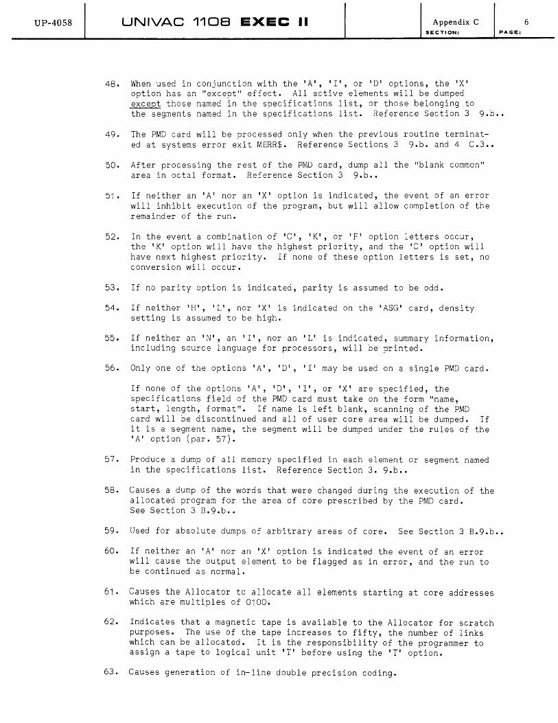
UP-4058 UNIVAC 1108 EXEC II Appendix C SECTION:
48. When used in conjunction with the 'A', 'I', or 'D' options, the 'X' option has an "except" effect. All active elements will be dumped except those named in the specifications list, or those belonging to
PAGE:
the segments named in the specifications list. Reference Section 3 9.b .•
49. The PMD card will be processed only when the previous routine terminated at systems error exit MERR$. Reference Sections 3 9.b. and 4 C.3 ••
50. After processing the rest of the PMD card, dump all the "blank common" area in octal format. Reference Section 3 9.b ••
51. If neither an 'A' nor an 'X' option is indicated, the event of an error will inhibit execution of the program, but will allow completion of the remainder of the run.
52. In the event a combination of 'C', 'K', or 'F' option letters occur, the 'K' option will have the highest priority, and the 'C' option will have next highest priority. If none of these option letters is set, no conversion will occur.
53. If no parity option is indicated, parity is assumed to be odd.
54. If neither 'H', 'L', nor 'X' is indicated on the 'ASG' card, density setting is assumed to be high.
55. If neither an 'N', an 'I', nor an 'L' is indicated, summary information, including source language for processors, will be printed.
56. Only one of the options 'A', 'D', 'I' may be used on a single PMD card.
If none of the options 'A', 'D', 'I', or 'X' are specified, the specifications field of the PMD card must take on the form "name, start, length, format". If name is left blank, scanning of the PMD card will be discontinued and all of user core area will be dumped. If it is a segment name, the segment will be dumped under the rules of the 'A' option (par. 57).
57. Produce a dump of all memory specified in each element or segment named in the specifications list. Reference Section 3. 9.b ••
58. Causes a dump of the words that were changed during the execution of the allocated program for the area of core prescribed by the PMD card. See Section 3 B.9.b ••
59. Used for absolute dumps of arbitrary areas of core. See Section 3 B.9.b ••
60. If neither an 'A' nor an 'X' option is indicated the event of an error will cause the output element to be flagged as in error, and the run to be continued as normal.
61. Causes the Allocator to allocate all elements starting at core addresses which are multiples of 0100.
62. Indicates that a magnetic tape is available to the Allocator for scratch purposes. The use of the tape increases to fifty, the number of links which can be allocated. It is the responsibility of the programmer to assign a tape to logical unit 'T' before using the 'T' option.
63. Causes generation of in-line double precision coding.
6
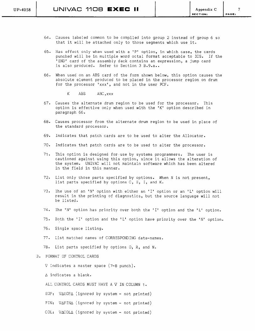
UP-40S8 UNIVAC 110B EXEC II Appendix C SECTION:
64. Causes labeled common to be compiled into group 2 instead of group 6 so that it will be attached only to those segments which use it.
65. Has effect only when used with a 'PI option, in which case, the cards punched will be in multiple word octal format acceptable to ICS. If the 'END' card of the assembly deck contains an expression, a jump card is also produced. Refer to Section 3 B.9.a ••
66. When used on an ABS card of the form shown below, this option causes the absolute element produced to be placed in the processor region on drum for the processor 'xxx', and not in the user PCF.
K ABS ABC,xxx
67. Causes the alternate drum region to be used for the processor. This option is effective only when used with the 'K' option described in paragraph 66.
68. Causes processor from the alternate drum region to be used in place of the standard processor.
69. Indicates that patch cards are to be used to alter the Allocator.
70. Indicates that patch cards are to be used to alter the processor.
71. This option is designed for~use by systems programmers. The user is cautioned against using this option, since it allows the alteration of the system. UNIVAC will not maintain software which has been altered in the field in this manner.
72. List only those parts specified by options. When N is not present, list parts specified by options C, E, I, and K.
73. The use of an 'N' option with either an 'I' option or an 'L' option will result in the printing of diagnostics, but the source language will not be listed.
74. The 'N' option has priority over both the 'I' option and the 'L' option.
75. Both the 'I' option and the 'L' option have priority over the 'N' option.
76. Single space listing.
77. List matched names of CORRESPONDING data-names.
78. List parts specified by options 0, R, and N.
3. FORMAT OF CONTROL CARDS
V indicates a master space (7-8 punch).
6 indicates a blank.
ALL CONTROL CARDS MUST HAVE A V IN COLUMN 1.
EOF: V6EOF6 (ignored by system - not printed)
FIN: V6FIN6 (ignored by system - not printed)
COL: V6COL6 (ignored by system - not printed)
7 PAGE:

UP-40S8 UNIVAC 1108 EXEC II
RUN: 7ARUN f1, f2, f3, f4, f5, f6
~ is an option letter and may be omitted.
Appendix C SECTION:
At least one blank must precede and at least one blank must follow the mnemonic 'RUN ' • Spaces may follow but may not precede each of the commas (,).
Fields f3, f4, f5, and f6 are optional.
The last of the fields f2, f3, f4, f5, and f6 must be followed by a blank and not by a comma.
Reference: Section 3 B.1 .a ..
PAGE:
ASG: voptions~ ••• ~ASG~ ••. ~assignment, assignment, ••• assignment (Form I)
v ~ ••• 6.ASG6. •.• 6.c/u, c/u, •••
voptions6. ••• 6.ASG6. ... 6.c/u,c/u, ••• assignment
Options may not appear on ASG cards of form II.
(Form II)
(Form III)
At least one blank must precede and at least one blank must follow the mnemonic 'ASG'.
Blanks may follow but not precede commas (,) and slashes (/), and equal signs (=) in assignments.
The last unit number, u, on cards of form II and form III must be followed by a blank and not by a comma.
Reference: Section 3 B.1.b ••
MSG: voptions6. ••• 6,MSG6.message to be printed begins with first non-blank character.
At least one blank must precede and at least one blank must follow the control card mnemonic, 'MSG'.
Reference: Section 3 B.2 ••
HDG: voptions~ ••• 6.HDG6. ••• message to be printed appears in columns 13 through 72.
At least one blank must precede and at least one blank must follow the control card mnemonic, 'HDG'.
Reference: Section 3 B.3.c ••
TPR: voptions: ••• 6.TPR6. (rest of card ignored).
At least one blank must precede and at least one blank must follow the control card mnemonic, 'TPR ' •
Reference: Section 3 B.3.b.
8

UP-4058 UNIVAC 1108 EXEC II Appendix C SECTION:
DPR: 9~ ••• ~DPR~ (rest of card ignored).
There are no valid option letters for DPR.
At least one blank must precede and at least one blank must follow the control card mnemonic, 'DPR'. Reference: Section 3 B.3.b.
PAGE:
4. FORMAT OF PROCESSOR CONTROL CARDS
ASM: COB: FOR: MAP:
PDP:
Voptions~ •.. ~xxx, lac f1, f2, f3 (flags)
The mnemonic, 'xxx', must be preceded by at least one blank; it must be followed by either a comma and the 'lac' field, or by a series of one or more blanks. The 'lac' field is defined as a single letter (A-Z) or an asterisk (*) preceded by an optional string of blanks and followed by a required string of one or more blanks. Each of f1, f2, f3 is a name or a name/version. Blanks may follow but may not precede a slash (/) or a comma separating f1, f2, and f3.
If flags are specified, a left parenthesis and a string of letters (A-Z) containing no blanks must immediately follow the last of f1, f2, f3. The string of letters must be terminated by a blank, or by a right parenthesis followed by a blank. The fields f2, and f3 are optional and may be omitted. The last of f1, f2, f3 must be followed by a blank if flags are not specified.
Reference: Sections 3 B.4.a., 3 B.4.b., 2 B.4.c., 3 B.5.a ••
CLP: Voptions~ ••• ~xxx,loc LFT:
f1 ,f2
XQT:
The mnemonic, 'xxx', must be preceded by at least one blank; it must be followed either by a comma and the 'lac' field, or by a series of one or more blanks. The 'lac' field is defined as a single letter (A-Z) or a (*), preceded by an optional string of blanks. f1 and f2 are of the form name or name/version. Blanks may follow but not precede a slash (/), or the comma separating f1 and f2. f2 is optional and may be omitted, in which case f1 must be followed by a blank and not by a comma.
Reference: Sections 3 B.4.a., 3 B.4.b., 4 A.1 ••
SeD: 90ptions~ ••• ~xxx~ ••• ~ f1,f2 ABS:
The mnemonic, 'xxx', must be preceded and followed by at least one blank. f1 and f2 are of the form 'name' or 'name/version'. Blanks may follow but not precede a slash (/) or a comma. f2 is optional and may be omitted on ABS and SCD; it must be omitted on XQT. If f2 is omitted, f1 must be followed by a blank and not by a comma.
Reference: Section 3 B.5.b.
ELT: 9~ •.. ~ELT~ •.. ~ f1, f2, f3, f4
The mnemonic, 'ELT', must be preceded and followed by at least one blank. f1 is of the form 'name/version (flags)'. Both 'version' 'flags' are optional, but if flags are included a left parenthesis must directly follow the last letter of the version or the last letter of the name if version is omitted. Following the left parenthesis is a string of flag letters containing no blanks, and terminated by a
9

UP-4058 UNIVAC 110B EXEC II Appendix C SECTION:
Ies: LBR:
right parenthesis. Blanks may follow but not precede commas and the slash (/). f2, f3, and f4 are optional and may be omitted. The last of f1, f2, f3, and f4 must be followed by at least one blank.
Reference: Section 3 B.6.a ••
\l t:. • • • t:.xxx
The mnemonic, 'xxx', must be preceded and followed by at least one blank.
Reference: Sections 3 B.7., and 3 B.9.a ••
PMD: \loptions~ ••• ~PMD~ ... ~specifications
The mnemonic, 'PMD', must be preceded and followed by at least one blank. The specifications field is of the form 'name1', 'name2' , •.• , 'namen' or 'name', 'start', 'length', 'format'. In either case, blanks may follow but may not precede commas. This card has a fixed format in certain cases.
Reference: Section 3 B.9.b.
10 PAGE:
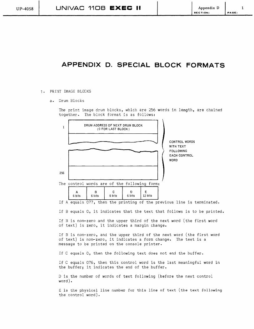
UP-4058 UNIVAC 1108 EXEC II Appendix D SECTION:
APPENDIX D. SPECIAL BLOCK FORMATS
1. PRINT IMAGE BLOCKS
a. Drum Blocks
The print image drum blocks, which are 256 words in length, are chained together. The block format is as follows:
256
DRUM ADDRESS OF NEXT DRUM BLOCK (0 FOR LAST BLOCK)
---------------------------------~~ - - -
The control words are of the following form:
A B C D E 6 bits 6 bits 6 bits 6 bits 12 bits
CONTROL WORDS
WITH TEXT
FOLLOWING
EACH CONTROL
WORD
If A equals 077, then the printing of the previous line is terminated.
If B equals 0, it indicates that the text that follows is to be printed.
If B is non-zero and the upper third of the next word (the first word of text) is zero, it indicates a margin change.
If B is non-zero, and the upper third of the next word (the first word of text) is non-zero, it indicates a form change. The text is a message to be printed on the console printer.
If C equals 0, then the following text does not end the buffer.
If C equals 076, then this control word is the last meaningful word in the buffer; it indicates the end of the buffer.
D is the number of words of text following (before the next control word) •
E is the physical line number for this line of text (the text following the control word).
1 PAGE:
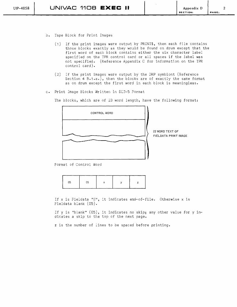
UP-4058 UNIVAC 1108 EXEC II
b. Tape Block for Print Images
Appendix D SECTION:
(1) If the print images were output by PRINT$, then each file contains those blocks exactly as they would be found on drum except that the first word of each block contains either the six character label specified on the TPR control card or all spaces if the label was not specified. (Reference Appendix C for information on the TPR control card).
(2) If the print images were output by the DMP symbiont (Reference Section 4 B.1 .a.), then the blocks are of exactly the same format as on drum except the first word in each block is meaningless.
c. Print Image Blocks Written in DLT-5 Format
The blocks, which are of 23 word length, have the following format:
CONTROL WORD
~---------------~--------------------~
Format of Control Word
05 05 x y z
22 WORD TEXT OF
FIELDATA PRINT IMAGE
If x is Fieldata "E", it indicates end-of-file. Otherwise x is Fieldata blank (05).
If Y is "blank" (05), it indicates no skip; any other value for y indicates a skip to the top of the next page.
z is the number of lines to be spaced before printing.
2 PAGE:

UP-4058 UNIVAC 110B EXEC II Appendix D SECTION:
2. CARD IMAGE BLOCKS
a. Drum Blocks
2
255
256
The blocks, which have length of 256 words, are chained together. The block format is as follows:
CHAIN TO NEXT DRUM BLOCK (0 FOR LAST BLOCK OF CHAIN)
o FOR 80 COLUMN CARDS NUMBER OF CARD IMAGES 1 FOR 90 COLUMN CARDS IN THIS BLOCK
----- - --- --------------------------------- WORDS 3-256
CONTAIN 14
WORDS (OR 15
WORDS FOR 90
COLUMN CARDS)
CARD IMAGES.
b. Tape Blocks
Tape blocks for card images are output by the DMP symbiont. They have the same format as the drum blocks for card images, except that the first word of each block is meaningless.
3. PAPER TAPE IMAGES ON MAGNETIC TAPE (via symbiont action)
Each block of data has the following format:
o
2
3
253
254
255
NOT USED
NOT USED I IMAGE COUNT
1st IMAGE 2nd IMAGE 3rd IMAGE
4th IMAGE ETC.
- ----
r-'--"=-------.l
O~image count~76210
Character images are packed left to right in thirds of words starting with the third word of each block. A punch in the paper tape corresponds to a 1 bit in the image, channel 1 will occupy the least significant bit position and sequential channels occupy sequential bit positions proceeding leftward in the image.
3 PAGE:

UP-4058 UNIVAC 1108 EXEC II Appendix D
SECTION:
Each file contains any number of data blocks followed by a hardware end-offile mark. A single tape reel may contain any number of files.
Unless the file spans two tape reels - (See next paragraph), the end of tape indication is of the following structure:
(1) A ten word block of the form:
;0: 1 : 1 ~ 1 : I: I
8 9
- -any bit configuration
(2) A hardware end-of-file mark following the above block.
If a file spans more than one tape reel, then the end of tape indication is replaced by the following structure.
(1) The first tape may contain any number of files followed by any number of blocks of the last file.
(2) The file to be continued must be followed directly by a ten word block of the format:
o [ : 1 : I : I : I_~ 1 ~ I 7
8
9
- _ ....
any bit configuration
(3) A hardware end-of-file mark must follow the above "end reel" block.
4. PROGRAM ELEMENTS ON MAGNETIC TAPE (via CUR)
An element is recorded on magnetic tape by means of the same card images that are punched into cards, and therefore, the ELT card is a part of the element. When the elements of the PCF are written on tape, (such as with the CUR operations TWR or OUT), the TOC of the PCF does not accompany the elements; the TOC is reconstructed when the elements on the tape are reentered into the PCF. The tape format is shown pictorially where:
(1) "Beginning Sentinel" is the name of the element for the first block of an element and plus zero for all other blocks.
(2) "Item Count" indicates in binary the number of card images in the block. It may vary from zero to 36.
4 PAGE:

UP-4058 UNIVAC 1108 EXEC II Appendix D
SECTION:
(3) "Ending Sentinel" is plus zero for all but the last block of an element for which it is minus zero. Block size for tape elements is fixed at 507 words. The unused portion of a block, past the last card image, contains filler.
BEGINNING SENTINEL
ITEM COUNT
FIRST CARD IMAGE IN THIS BLOCK
LAST CARD IMAGE IN THIS BLOCK (THERE MAY BE NO MORE THAN 36 CARD IMAGES PER TAPE BLOCK)
ENDING SENTINEL
5. BLOCK BUFFERING PACKAGE FILE DESCRIPTION TABLE
Note: In the following format illustrations and discussion the fields enclosed in parentheses are filled in by the package and are not normally of concern to the user.
Word 1
2
3
4
35
5 I
Location of Drum Block Pool
(End of Queue)
(User's Buffer)
Length of Information
3029 24 23 18 17
LAF I (AB) I (LOCK)
I
Location of Buffer Pool
(Start of Queue)
Abnorma I Return
Location of Information
12 11 6 5 0
(RQ) I (MODE) I (DEVICE I
5 PAGE:

UP-4058 UNIVAC 1108 EXEC II
6 Device Error Return Calling Sequence Error Return
7 Input Device Routines Output Device Routines
8 Block Size (Cur rent Buffer)
9 Command Word
10 Sentinel Word
In i ti a I Drum Address
Word 11
UC*
Final Drum Address
12
Available Space Count *
(Access Word)
13
not used
Current Drum Address
14
not used
* For Tape Fi les.
Appendix D
SECTION:
Alternates
Alternates
Alternates
Alternates
6 PAGE:
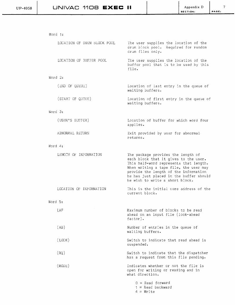
UP-40S8 UNIVAC 1108 EXEC II Appendix D SECTION:
Word 1:
LOCATION OF DRUM BLOCK POOL
LOCATION OF BUFFER POOL
Word 2:
(END OF QUEUE)
(START OF QUEUE)
Word 3:
(USER'S BUFFER)
ABNORMAL RETURN
Word 4:
LENGTH OF INFORMATION
LOCATION OF INFORMATION
Word 5:
LAF
(AB)
( LOCK)
(RQ)
(MODE)
The user supplies the location of the drum block pool. Required for random drum files only.
The user supplies the location of the buffer pool that is to be used by this file.
Location of last entry in the queue of waiting buffers.
Location of first entry in the queue of waiting buffers.
Location of buffer for which word four applies.
Exit provided by user for abnormal returns.
The package provides the length of each block that it gives to the user. This half-word represents that length. When writing a tape file, the user may provide the length of the information he has just placed in the buffer should he wish to write a short block.
This is the initial core address of the current block.
Maximum number of blocks to be read ahead on an input file (look-ahead factor).
Number of entrjes in the queue of waiting buffers.
Switch to indicate that read ahead is suspended.
Switch to indicate that the dispatcher has a request from this file pending.
Indicates whether or not the file is open for writing or reading and in what direction.
o = Read forward 1 = Read backward 4 = Write
7 PAGE:
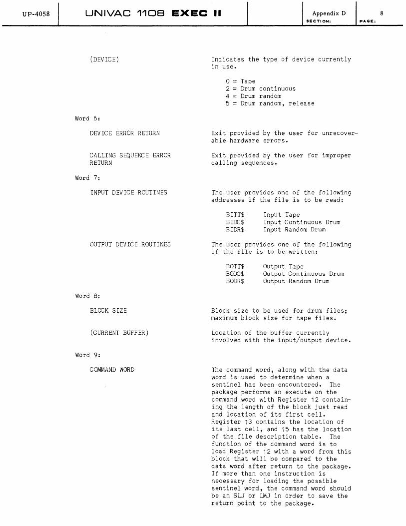
UP-40S8 UNIVAC 1108 EXEC II Appendix D SECTION:
(DEVICE)
Word 6:
DEVICE ERROR RETURN
CALLING SEQUENCE ERROR RETURN
Word 7:
INPUT DEVICE ROUTINES
OUTPUT DEVICE ROUTINES
Word 8:
BLOCK SIZE
(CURRENT BUFFER)
Word 9:
COMMAND WORD
Indicates the type of device currently in use.
o = Tape 2 = Drum continuous 4 = Drum random 5 = Drum random, release
Exit provided by the user for unrecoverable hardware errors.
Exit provided by the user for improper calling sequences.
The user provides one of the following addresses if the file is to be read:
BITT$ BIDC$ BIDR$
Input Tape Input Continuous Drum Input Random Drum
The user provides one of the following if the file is to be written:
BOTT$ BODC$ BODR$
Output Tape Output Continuous Drum Output Random Drum
Block size to be used for drum files; maximum block size for tape files.
Location of the buffer currently involved with the input/output device.
The command word, along with the data word is used to determine when a sentinel has been encountered. The package performs an execute on the command word with Register 12 containing the length of the block just read and location of its first cell. Register 13 contains the location of its last cell, and 15 has the location of the file description table. The function of the command word is to load Register 12 with a word from this block that will be compared to the data word after return to the package. If more than one instruction is necessary for loading the possible sentinel word, the command word should be an SLJ or LMJ in order to save the return point to the package.
8 PAGE:

UP-40S8 UNIVAC 1108 EXEC II Appendix D SECTION:
Word 10:
SENTINEL WORD
FOR DRUM FILES ONLY
Word 11:
INITIAL DRUM ADDRESS
Word 12:
FINAL DRUM ADDRESS
Word 13:
(ACCESS WORD)
Word 14:
(CURRENT DRUM ADDRESS)
All volatile registers are available for use. The command word is executed by the package while in interrupt coding. Normally, no reference to the system should be made.
After execution of the Command Word, equality of Register 12 and the sentinel word implies a sentinel.
When writing, user must supply the first location of the drum area which is to be used for a continuous drum file. When writing in the random drum mode, the package will set the initial drum address. When reading forward, the information will be read beginning with this block. When reading backward, an abnormal return results from reading past the addressed block.
The user must supply the last drum location to be used by the package for writing a continuous drum file. Since it is assumed that the same file description table is to be used for writing and reading, the package will replace this value with the location of the last block used by this file when it is closed after writing. If a file is being read forward, an abnormal return results from reading past the final drum address. Reading commences with this address when a file is opened backwards. When reading, the final drum address is the first word of the last block read.
Access word for buffer currently involved with the drum system.
Drum address for the buffer currently involved with the drum system.
9 PAGE:

UP-4058 UNIVAC 1108 EXEC II Appendix D SECTION:
FOR TAPE FILES ONLY
Word 11:
UC
Word 12:
The user specifies the logical unit to be used.
AVAILABLE SPACE COUNT The user specifies the number of words of available tape on the reel to be written. This available space is counted down by the package as the reel is written. An abnormal return occurs when writing two more blocks of maximum size would exhaust the tape.
The information in the file description area, which is dependent on device and I/O, need only be included as indicated. The following check list should serve as a guide for the fields required when a file is to be opened. Other fields are either filled in by the package itself or are ignored.
a. Always Required
For all modes:
Name of buffer pool Block size Abnormal return Device error return Calling sequence error return
b. Open File For Output
For tape files:
Output device routine - BOTT$ UC Available space count
For continuous drum files:
Output device routine - BODC$ Initial drum address Final drum address
For random drum files:
Location of drum block pool Output device routine - BODR$
c. Open File For Input
For tape files:
LAF Input device routine - BITT$ Command word Data word UC
10 PAGE:

UP-4058 UNIVAC 110B EXEC II Appendix D
SECTION:
For continuous drum files:
LAF Input device routine - BIDC$ Command word Data word Initial drum address Final drum address
Left in place if file was written using this file description area.
For random drum file:
Location of drum block pool LAF Input device routine - BIDR$ Command word Data word Initial drum address Final drum address
Left in place if file was written using this file description area.
6. LABEL and ITEM PACKAGE FORMATS
a. Format of the File Description Area
The label and item handling routines require seven additional words following the file description area (see Appendix D 5.)
Word 15 IS (BLOCK COUNT)
16 (Storage for Routine) (Storage for Routine)
17 (Storage for Routine) ( Item Count)
18 NL LOCL
19 NF LOCF
20 EOFX REW
21 EORR EORW
22 (Size) LABEX
FILE DESCRIPTION AREA
Those fields enclosed in parentheses are filled in by the package and are not normally of concern to the user.
Word 15:
IS
(BLOCK COUNT)
Word 16:
(STORAGE FOR ROUTINE)
The user supplies the item size. The item size is some non-zero value for fixed length items and zero for variable length items.
The number of blocks used for this file.
Words 16 and the left half of word 17 are used by the item handlers as location pointers.
11 PAGE:

UP-40S8 UNIVAC 1108 EXEC II Appendix 0 SECTION:
Word 17:
(ITEM COUNT)
Word 18:
NL
Lex:: L
Word 19:
NF
Lex::F
Word 20:
EOFX
REW
Word 21:
EORR
EORW
While writing, the number of items in current buffer. While reading, the number of items remaining in current buffer.
The number of label image words.
The location of the file label image. A zero means no label exists.
The number of free words.
The location of the free words. Zero implies no free words.
Exit provided by user for end-of-files.
The rewind conditions for tape are as follows:
o = No rewind 1 = Rewind 2 = Rewind with interlock
The end-of-reel exit for reading is provided by the user. If this is set to zero, the standard ending-reel procedure is used.
When control is transferred to the end-of-reel exit X11 if entered, contains a return point to the Label Package.
The end-of-reel exit for writing is provided by the user. If this is set to zero, the standard ending-reel procedure is used.
When control is transferred to the end-of-reel exit X11 if entered, contains a return point to the Label Package.
12 PAGE:

UP-4058
2
3
4
5
6
Word N- 2
Word N-1
Word N
UNIVAC 1108 EXEC II
b. Format of Label Block
7 4 7 5 7 4 7 5 7 4 7
6 I Block Count Usable Tape
Block Length - Current Fi Ie Item Size - Current Fi Ie
Number of File Label Words Number of Free Words
Date of Recording (Field Data Code)
Disregarded Reel Number (Binary)
Label Words
-- -
Free Words
Disregarded Words
Block Length-Previous File Item Size - Prev ious Fi Ie
6 Block Count Usable Tape
7 4 5 7 4 7 5 7 4 7
LABEL BLOCK
5
5
Appendix D SECTION:
~
File
Label
Free
Words
Balance
of Block
if Any
~"
233 Words for
240 Word
Blocks
or
113 Words for 120 Word Blocks
Word 1 and word N contain the sentinel identification word 747574757475 (octal). Word 2 and word N-1 contain the label sentinel 6 (octal) bits 00-02, block count bits 03-17 and usable tape bits 18-35. Word 2 describes the initial condition for the file. Word N-1 describes the updated condition for the file. Word 3 described the current file, and word N-2 describes the previous file (if any). Word 5 is the first word of the file image and is the date of recording in Fieldata code. The high-order half of word 6 contains the reel number.
13 PAGE:
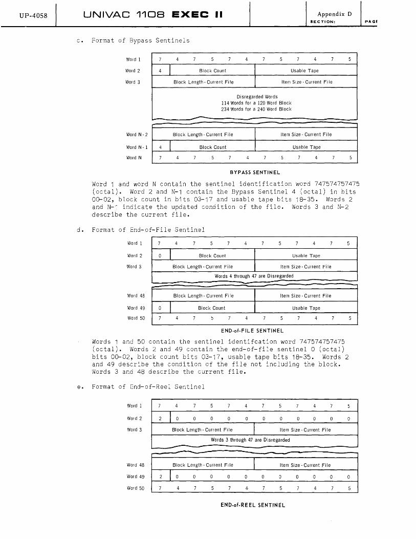
UP-40S8 UNIVAC 110B EXEC II
c. Format of Bypass Sentinels
Word 1 7 4 7 5 7
Word 2 4 I Block Count
Word 3 Block Length - Current Fi Ie
4 7
Disregarded Words
5 7
Appendix 0 SECTION:
4 7 5
Usable Tape
Item Size - Current Fi Ie
114 Words for a 120 Word Block 234 Words for a 240 Word Block
-- -
Word N - 2 Block Length - Current File Item Size - Current Fi Ie
Word N-l 4 I Block Count Usable Tape
Word N 7 4 7 5 7 4 7 5 7 4 7 5
BYPASS SENTINEL
-
Word 1 and word N contain the sentinel identification word 747574757475 (octal). Word 2 and N-1 contain the Bypass Sentinel 4 (octal) in bits 00-02, block count in bits 03-17 and usable tape bits 18-35. Words 2 and N-1 indicate the updated condition of the file. Words 3 and N-2 describe the current file.
d. Format of End-of-File Sentinel
Word 1 7 4 7 5 7 4 7 5 7 4 7 5
Word 2 0 I Block Count Usable Tape
Word 3 Block Length - Current File Item Size - Current Fi Ie
Words 4 through 47 are Disregarded -Word 48
Word 49
Word 50
,--
0 I 7
~
Block Length - Current Fi Ie Item Size - Current Fi Ie
Block Count Usable Tape
4 7 5 7 4 7 5 7 4 7
END-of-FILE SENTINEL
Words 1 and 50 contain the sentinel identifcation word 747574757475 (octal). Words 2 and 49 contain the end-of-file sentinel 0 (octal) bits 00-02, block count bits 03-17, usable tape bits 18-35. Words 2 and 49 describe the condition of the file not including the block. Words 3 and 48 describe the current file.
e. Format of End-of-Reel Sentinel
5
Word 1 7 4 7 5 7 4 7 5 7 4 7 5
Word 2 2 I 0 0 0 0 a a 0 a 0 a 0
Word 3 Block Length - Current Fi Ie 1 Item Size - Current Fi Ie
Words 3 through 47 are Disregarded --- - -Word 48 Block Length - Current Fi Ie J Item Size - Current Fi Ie
Word 49 2 J a 0 0 0 0 0 0 0 0 0 0
Word 50 7 4 7 5 7 4· 7 5 7 4 7 5
END-of-REEL SENTINEL
-
PAGE

UP-40S8 UNIVAC 1108 EXEC II Appendix D SECTION:
Words 1 and 50 contain the sentinel identification 747574757475 (octal). Words 2 and 49 contain the end-of-reel sentinel 2 (octal) bits 00-02, block count bits 03-17, usable tape bits 18-35. Words 2 and 49 describe the condition of the file not including the block. Words 3 and 48 describe the current file.
f. Format of Fixed-Length Item Data Block
Word 1 Number of Items in Block I Number of Words in Block
Word 2 1st Fixed Length Item
2nd Fixed Length Item
L-. ----- - - ----...-N - 1st Fixed Length Item
Nth Fixed Length Item
Disregarded Words (if any)
Word N-2 I Number of Disregarded Items (if any)
Word N-1 Check Sum
Word N Number of Items in Block 1 Number of Words in Block
FIXED-LENGTH ITEM DATA BLOCK
Words 1 and N describe how many items are contained in the data block and the size of the block. If the block has any disregarded words, the "number of words in block" will be negative. There will be no disregarded words in a block of a tape file unless required to bring the block up to the 120 or 240 word minimum. Drum files will always contain full sized blocks as described in word 8 of the file description area. The number of disregarded words will be made sufficient to fill out the block. Word 2 is the first word of the first item. Word N-1 contains the sum for the entire data block excluding the N-1st word of the block. The right half of words 1 and N will be negative if the data block has any disregarded words. If there are disregarded words in the block, then the right half of word N-2 contains the number of these words. Otherwise, it is the last word of the last item in the block.
15 PAGE:
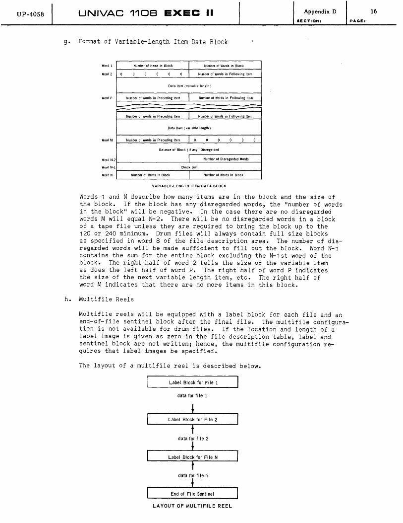
UP-4058 UNIVAC 1108 EXEC II Appendix D
SECTION:
g. Format of Variable-Length Item Data Block
Word 1 Number of Items in Block I Number of Words in Block
Word 2 0 0 0 0 0 0 I Number of Words in Following Item
Data Item (variable length)
Word P Number of Words in Preceding Item I Number of Words in Following Item
<---
Number of Words in Preceding Item I Number of Words in Following Item
Data Item (variable length)
Word M Number of Words in Preceding Item I 0 0 0 0 0 0
Balance of Block (if any) Disregarded
Word N-2 I Number of Disregarded Words
Word N-I Check Sum
Word N Number of Items in Block I Number of Words in Block
VARIABLE-LENGTH ITEM DATA BLOCK
Words 1 and N describe how many items are in the block and the size of the block. If the block has any disregarded words, the "number of words in the block" will be negative. In the case there are no disregarded words M will equal N-2. There will be no disregarded words in a block of a tape file unless they are required to bring the block up to the 120 or 240 minimum. Drum files will always contain full size blocks as specified in word 8 of the file description area. The number of disregarded words will be made sufficient to fill out the block. Word N-1 contains the sum for the entire block excluding the N-1st word of the block. The right half of word 2 tells the size of the variable item as does the left half of word P. The right half of word P indicates the size of the next variable length item, etc. The right half of word M indicates that there are no more items in this block.
h. Multifile Reels
Multifile reels will be equipped with a label block for each file and an end-of-file sentinel block after the final file. The multifile configuration is not available for drum files. If the location and length of a label image is given as zero in the file description table, label and sentinel block are not written; hence, the multifile configuration requires that label images be specified.
The layout of a multifile reel is described below.
Label Block for File 1
data for fi Ie 1
Labe I Block for Fi Ie 2
t data for file 2
Label Block for Fi Ie N
data for file n
i End of Fi Ie Sentinel
LAYOUT OF MULTIFILE REEL
16
PAGEl

UNIVAC DIVISIDN DF ."'ERRV RAND CDR"'DRATIDN
U P·4058


